HAT700 Series HAT700/HAT700I/HAT700B/HAT700BI/HAT700S ATS CONTROLLER USER MANUAL
|
|
|
- Beverly Walsh
- 6 years ago
- Views:
Transcription

1 HAT700 Series HAT700/HAT700I/HAT700B/HAT700BI/HAT700S ATS CONTROLLER USER MANUAL ZHENGZHOU SMARTGEN TECHNOLOGY CO.,LTD
2 Software Version Version Date Note Original release HAT700s is added Renew character strings. Clarification of notation used within this publication. SIGN INSTRUCTION Note Caution! Warning! Highlights an essential element of a procedure to ensure correctness. Indicates a procedure or practice, which, if not strictly observed, could result in damage or destruction of equipment. Indicates error operation may cause death, serious injury and significant property damage.
3 CONTENT HAT700 SERIES ATS CONTROLLER 1 OVERVIEW ORDER INFORMATION AND MODULES COMPARISON ORDER INFORMATION MODULES COMPARISON PERFORMANCE AND CHARACTERISTICS SPECIFICATION MEASURE AND DISPLAY DATA OPERATION INDICATORS KEY FUNCTION DESCRIPTION LCD DISPLAY MAIN SCREEN STATUS DESCRIPTION S1 VOLTAGE STATUS S2 VOLTAGE STATUS GENSET STATUS SWITCH STATUS WARN ALARMS FAULT ALARMS INDICATION OTHERS MAIN MENU START/STOP OPERATION MANUAL START/STOP Panel Start/Stop Remote Start/Stop AUTO START/STOP Input Port Start/Stop Operation S1 Gens S2 Gens Start/Stop Scheduled Run Scheduled Not Run PARAMETERS CONFIGURATION PARAMETERS TABLE INPUT/OUTPUT FUNCTION DESCRIPTION Input Ports Function Output Ports Function HAT700 SERIES ATS CONTROLLER Version 1.2 Page 4 of 59
4 8.2.3 Custom Period Output DEFINITE TIME DELAY AND INVERSE DEFINITE MINIMUM TIME SETTING EVENT LOG ATS OPERATION MANUAL OPERATION AUTOMATIC OPERATION SYNC CLOSING ATS POWER SUPPLY LOAD SHEDDING COMMUNICATION CONFIGURATION DESCRIPTION OF CONNECTING TERMINALS TYPICAL WIRING DIAGRAM INSTALLATION FAULT FINDING HAT700 SERIES ATS CONTROLLER Version 1.2 Page 5 of 59
5 1 OVERVIEW HAT700 SERIES ATS CONTROLLER HAT700 series ATS controller is intelligent dual-supply module with configurable function, automatic measurement, LCD display, and digital communication. It combines digital, intelligence and networking. Automatic measurement and control can reduce incorrect operation. It is an ideal option for ATS. The powerful Microprocessor contained within the unit allows for precision voltage (2-way-3-phase) measuring and make accurate judgment; in addition, the corresponding digital output port will active when there is over/under voltage, over/under frequency, loss of phase and other abnormal condition occurs. This controller has full consideration in various application of ATS (automatic transfer system) and can be directly used for PC ATS, CB ATS, CC ATS etc. It has compact structure, advanced circuits, simple wiring and high reliability, and can be widely used in electrical devices, automatic control and testing system of electric power, telecommunications, petroleum, coal, metallurgy, railways, municipal administration, intelligent building, etc. HAT700 SERIES ATS CONTROLLER Version 1.2 Page 6 of 59
6 2 ORDER INFORMATION AND MODULES COMPARISON HAT700 SERIES ATS CONTROLLER 2.1 ORDER INFORMATION 2.2 MODULES COMPARISON Function AC DC AC Power Sync Input Ports Output Ports Current Power Supply Close (Fixed+Config.) (Fixed+Config.) Type & Power RS485 HAT HAT700B (LN90V~280V) HAT700I HAT700BI 2+4 (LN90V~280V) 2+6 HAT700S 2+4 (LN90V~280V) 2+6 HAT700 SERIES ATS CONTROLLER Version 1.2 Page 7 of 59
7 2.3 PERFORMANCE AND CHARACTERISTICS System type can set as: S1 (Mains) & S2 (Mains), S1 (Mains) & S2 (Generator), S1 (Generator) & S2 (Mains), S1 (Generator) & S2 (Generator). 132x64 LCD with backlight, multilingual interface (including English, Chinese or other languages), push-button operation. Collect and display 2-way 3-phase Voltage, Frequency and Phase. Collect and display Active Power, Reactive Power, Apparent Power, Power Factor and Current. S1/S2 separated over current warning/ trip alarm NEL (Non-essential Load) trip function. Display S1/S2 Total kw Energy, Total kvar Energy, Total Close Times. Display continuous power supply time and S1/S2 total power supply time. Sync Transfer function; in addition, Voltage Difference, Frequency Difference and Phase Difference can be displayed. For Stored-Energy type ATS, its close relay will active after the PF Input is active. Over/under voltage, loss of phase, reverse phase sequence, over/under frequency protection. Phase Sequence Transfer function; Automatic/Manual mode. In manual mode, can force the switch to close or open; All parameters can be set on site. Passwords authentication ensures authorized staff operation only. The genset can be Manual Test on site to achieve start/stop operation. ATS Controller has function of automatic Re-closing. Closing output signal can be set as on intervals or as continuous output. Applicable for PC Three-stage, PC Two-stage, CB and CC switch. Applicable for 2 isolated neutral line. Real-time clock (RTC); Event log Function (Event log can record 99 items circularly) Scheduled Run & Scheduled Not Run (can be set as start genset once a day/week/month whether with load or not). Can control two generators to work as Cycle Run mode, Master Run mode and Balance Run mode. Widely power supply range DC(8~35)V allows the controller can bear 80V instantaneous current. Large terminal space allows the controller can bear maximum 625V input voltage. With RS485 isolated communication interface. With "remote controlling, remote measuring, remote communication, remote regulating" function by the ModBus communication protocol. HAT700 SERIES ATS CONTROLLER Version 1.2 Page 8 of 59
8 Can remote start/stop the genset and remote control the ATS to close or open. Suitable for various AC systems (3 phase 4-wires, 3-phase 3-wires, single-phase 2-wire, and 2-phase 3-wire). Modular design, self extinguishing ABS plastic shell, pluggable terminal, built-in mounting, compact structure with easy installation. HAT700 SERIES ATS CONTROLLER Version 1.2 Page 9 of 59
9 3 SPECIFICATION Items Operating Voltage Power Consumption AC Voltage Input HAT700 SERIES ATS CONTROLLER Contents 1. DC 8.0V~35.0V, continuous power supply. 2. AC90V~280V during AC power supply L1N1/L2N2 (HAT700B/HAT700BI /HAT700S). <5W (Standby mode: 2W) AC system HAT700/HAT700I HAT700B/HAT700BI/ HAT700S 3P4W (L-L) (80~625)V (80~480)V 3P3W (L-L) (80~625)V (80~625)V 1P2W (L-N) (50~360)V (50~280)V 2P3W (A-B) (80~625)V (80~480)V Rated Frequency Close Relay Output Auxiliary Relay Output Digital Input Communication Case Dimensions Panel Cutout Working Conditions Storage Condition Protection Level Insulation Strength Weight 50/60Hz 16A AC250V Volts free output 16A/7A AC250V Volts free output GND (B-) connect is active. RS485 isolated interface, MODBUS Protocol 197mmx152mmx47mm 186mmx141mm Temperature: (-25~+70) C; Humidity: (20~93)%RH Temperature: (-25~+70) C IP55 Gasket Apply AC2.2kV voltage between high voltage terminal and low voltage terminal; The leakage current is not more than 3mA within 1min. HAT700/HAT700I: 0.7kg HAT700B/HAT700BI/HAT700S: 0.8kg HAT700 SERIES ATS CONTROLLER Version 1.2 Page 10 of 59
10 4 MEASURE AND DISPLAY DATA HAT700 SERIES ATS CONTROLLER Data Items HAT700/ HAT700B HAT700I/ HAT700BI HAT700S S1/S2 Phase Voltage ( L1-N,L2-N,L3-N) S1/S2 Line Voltage ( L1-L2,L2-L3,L3-L1) S1/S2 Phase (L1-L2-L3) S1/S2 Frequency (L1) 3-Phase Current (I1,I2,I3) Phase Sequence (L1-L2-L3) 3-Phase Active Power kw(p1,p2,p3) 3-Phase Total Active Power kw(p1+p2+p3) 3-Phase Reactive Power kvar (Q1,Q2,Q3) 3-Phase Total Reactive Power kvar (Q1+Q2+Q3) 3-Phase Apparent Power kva(a1,a2,a3) Total Apparent Power kva(a1+a2+a3) 3-Phase Power Factor PF(PF1,PF2,PF3) Average Power Factor PF(PF1,PF2,PF3) Voltage Difference between S1 and S2 Frequency Difference between S1 and S2 Phase Angle between S1 and S2 Continuous Power Supply Time Continuous Power Supply Time (Last Time) S1 Total Power Supply Time S2 Total Power Supply Time S1 Total kw Energy kwh S2 Total kw Energy kwh S1 Total kvar Energy kvarh S2 Total kvar Energy kvarh S1 Total Close Times S2 Total Close Times Real Time Clock Event Log HAT700 SERIES ATS CONTROLLER Version 1.2 Page 11 of 59

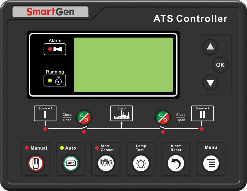
11 5 OPERATION HAT700 SERIES ATS CONTROLLER 5.1 INDICATORS INDICATORS DESCRIPTION Indicator Type Alarm Running S1 Power Normal S1 Close Status S2 Power Normal S2 Close Status Manual Mode Auto Mode Generator Start Description Slow flashing (1time per sec) when warn alarm occurs. Fast flashing (5 times per sec) when fault alarm occurs. Flash when module countdown running (1time per sec) It is light on when S1 is normal; flashing when S1 is abnormal ((1time per sec)); off when there is no S1 power. It is light on when S1 close input is activated. It is light on when S2 is normal; flashing when S2 is abnormal ((1time per sec)); off when there is no S2 power. It is light on when S2 close input is activated. It is light on when the module is in Manual mode. It is light on when the module is in Auto mode. It is light on when the Start signal is be initiated. HAT700 SERIES ATS CONTROLLER Version 1.2 Page 12 of 59
12 5.2 KEY FUNCTION DESCRIPTION Icon Button Name Function Description S1 Close/Open Active in Manual mode. Press this key, if S1 load is opened, then the S1 closing relay will be energized; if S1 load is closed, then the S1 opening relay will be energized. When sync closing is active, if S2 load is closed, press the key will energize the S1 Sync closing relay; During the S1 is waiting to synchronizing, pressing this key will de-energize the S1 sync closing relay. S2 Close/Open Active in Manual mode. Press this key, if S2 load is opened, then the S2 closing relay will be energized; if S1 load is closed, then the S2 opening relay will be energized. When sync closing is active, if S2 load is closed, press the key will energize the S2 Sync closing relay; During the S2 is waiting to synchronizing, pressing this key will de-energize the S2 sync closing relay. Manual Mode Auto Mode Trial Run Lamp Test Alarm Reset Menu Confirm Up/Increase Down/Decrease Set controller as Manual mode. Set controller as Auto mode. Press this key to enter into genset manual start/stop operation interface. Pressing and holding the key to enter lamp test mode, all LED lamps are lit and LCD screen display black. Press this key to enter into alarm interface; Pressing it again can clear fault alarm. Press this key to return the main screen; Press it again to enter into menu interface. When setting parameters, press this key to return prior menu. In main screen, press this key to scroll page. In menu screen, press this key can move cursor and confirm setting information. In main screen, press this key to scroll screen. In menu interface, press this key to up cursor or increase value in setting menu. In main screen, press this key to scroll screen. In menu interface, press this key to down cursor or decrease value in setting menu. HAT700 SERIES ATS CONTROLLER Version 1.2 Page 13 of 59
13 6 LCD DISPLAY HAT700 SERIES ATS CONTROLLER 6.1 MAIN SCREEN Status S1 Normal S2 Inactive Genset Standby S1 On Load Auto Mode Power U1LL V U1LN V Phase F Hz BAT 27.5V Auto Mode S1 Voltage Status S2 Voltage Status Genset Status Switch Status Current Mode, Alarm Status, Indications, Others S1 Line Voltage (L1-L2 L2-L3 L3-L1) S1 Phase Voltage S1 Phase S1 Frequency and genset battery voltage Current Mode, Alarm Status, Indications, Others U2LL 0 0 0V U2LN 0 0 0V Phase #### #### #### F2 0.00Hz Load 100% Auto Mode Load I A Phase TkW 329 PF 1.00 Tkvar 1.3 TkVa 330 Auto Mode kw kvar kva PF Auto Mode Sync Volt Diff. 74V x Freq Diff. 0.13Hz ok Phase Diff. 12 x S2 Line Voltage(L1-L2 L2-L3 L3-L1) S2 Phase Voltage S2 Phase S2 Frequency and present on-load percentage. Current Mode, Alarm Status, Indications, Others 3-phase current 3-phase current phase Total active power, power factor Total inactive power, Total apparent Power. Current Mode, Alarm Status, Indications, Others 3-phase active power 3-phase reactive power 3-phase apparent power 3-phase power factor Current Mode, Alarm Status, Indications, Others Volt Diff., D-value of 3-phase volt mean Freq Diff. Phase Diff. Auto Mode Current Mode, Alarm Status, Indications, Others Total HAT700 SERIES ATS CONTROLLER Version 1.2 Page 14 of 59
14 Cont. Power Suppy Time 5:25:18 Last Cont. Powe Supply 8:15:37 Auto Mode S1 Total Supply Time 125:25:18 S2 Total Supply Time 35:43:29 Auto Mode S1 Total kwh kWh S2 Total kwh kWh Auto Mode S1 Total kvarh kvarh S2 Total kvarh 672.4kvarh Cont. Power Suppy Time HH:MM:SS Last Cont. Powe Supply HH:MM:SS Current Mode, Alarm Status, Indications, Others S1 Total Supply Time HH:MM:SS S2 Total Supply Time HH:MM:SS Current Mode, Alarm Status, Indications, Others S1 Total kwh S2 Total kwh Current Mode, Alarm Status, Indications, Others S1 Total kvarh S2 Total kvarh Auto Mode S1 Total Close Nums S2 Total Close Nums Auto Mode Alarms Current Mode, Alarm Status, Indications, Others S1 Total Close Times S2 Total Close Times Current Mode, Alarm Status, Indications, Others Alarms 1/2 Warn Alarm S1 Over Current Fault Alarm S1 Failed to Closed Alarm number and account Alarm type(warn Alarm Fault Alarm) Alarm event Alarm type(warn Alarm Fault Alarm) Alarm event Others S1 S IN OUT (2)16:53:24 Auto Mode Inputs, outputs number Input status, S1/S2 closing input, 1~4 are configurable ports Output status, S1/S2 closing output, 1~6 are configurable ports Real-time clock Current Mode, Alarm Status, Indications, Others HAT700 SERIES ATS CONTROLLER Version 1.2 Page 15 of 59
15 RS485 Address 1 Baud Rate 9600 Stop Bit 2 Auto Mode RS485 Communication Communication Address RS485 Baud Rate RS485 Stop Bit Current Mode, Alarm Status, Indications, Others HAT700 SERIES ATS CONTROLLER 6.2 STATUS DESCRIPTION S1 VOLTAGE STATUS No. Item Description 1 S1 Available S1 Normal Delay 2 S1 Unavailable S1 Abnormal Delay 3 S1 Available Power supply voltage is within the setting range. 4 S1 Blackout Voltage is 0. 5 S1 Over Volt Voltage is higher than the set value. 6 S1 Under Volt Voltage has fallen below the set value. 7 S1 Over Freq Frequency is higher than the set value. 8 S1 Under Freq Frequency has fallen below the set value. 9 S1 Loss of Phase Loss of any phase of A, B and C. 10 S1 Phase Seq Wrong A-B-C phase sequence is wrong S2 VOLTAGE STATUS No. Item Description 1 S2 Available S2 Normal Delay 2 S2 Unavailable S2 Abnormal Delay 3 S2 Available Power supply voltage is within the setting range. 4 S2 Blackout Voltage is 0. 5 S2 Over Volt Voltage is higher than the set value. 6 S2 Under Volt Voltage has fallen below the set value. 7 S2 Over Freq Frequency is higher than the set value. 8 S2 Under Freq Frequency has fallen below the set value. 9 S2 Loss of Phase Loss of any phase of A, B and C. 10 S2 Phase Seq Wrong A-B-C phase sequence is wrong. HAT700 SERIES ATS CONTROLLER Version 1.2 Page 16 of 59
16 GENSET STATUS No. Item Description 1 Genset Start Delay Delay time before genset start 2 Genset Return Delay Delay time before genset stop 3 Scheduled Not Work When scheduled not run is active, its duration time will be displayed. 4 Scheduled Work When scheduled run is active, its duration time will be displayed. 5 Gen1 Cycle Run S1 cycle run countdown will be terminated when cycle start is active. 6 Gen2 Cycle Run S2 cycle run countdown will be terminated when cycle start is active. 7 S1 Genset Working Active when system type is S1 Gens S2 Gens. 8 S2 Genset Working Active when system type is S1 Gens S2 Gens. 9 Genset Working Genset start signal output. 10 Genset Standby There is no start genset signal output SWITCH STATUS No. Item Description 1 Ready to Transfer Switch transfer begins. 2 Closing S1 S1 closing delay is in progress. 3 Opening S1 S1 opening delay is in progress. 4 Closing S2 S2 closing delay is in progress. 5 Opening S2 S2 opening delay is in progress. 6 Transfer Rest Interval time between switch transfer 7 Closing S1 Again When the S1 Fail to open condition occurs, it s the delay time before the close relay is active for the second time. 8 Opening S1 Again When the S1 Fail to close condition occurs, it s the delay time before the open relay is active for the second time. 9 Closing S2 Again When the S2 Fail to open condition occurs, it s the delay time before the close relay is active for the second time. 10 Opening S2 Again When the S2 Fail to close condition occurs, it s the delay time before the open relay is active for the second time. 11 Waiting Sync It s the delay time that waiting S1 and S2 sync requirements (volt diff. freq diff. phase diff.) are satisfied. 12 Sync Closing S1 Sync closing S1 is active when the sync requirements are satisfied. 13 Sync Closing S2 Sync closing S2 is active when the sync requirements are satisfied. 14 Waiting S1 PF Before S1 is closed, it s the delay time to confirm S1 PF Input signal is active. HAT700 SERIES ATS CONTROLLER Version 1.2 Page 17 of 59
17 15 Waiting S2 PF Before S2 is closed, it s the delay time to confirm S2 PF Input signal is active. 16 Elevator Delay Elevator control output before ATS transfer. 17 S1 On Load S1 was already closed and S1 is taking load. 18 S2 On Load S2 was already closed and S2 is taking load. 19 Offload Switch was already opened and load is disconnect WARN ALARMS Warn alarms are active when controller detects the alarm signals. Alarm indicator will flash slowly (1time per sec) while illuminated when alarm reset. Warn alarms are not latched. No. Item Description 1 S1 Over Current Warn When the S1 current has exceeded the pre-set value and the action select Warn, it will initiate a warning alarm. 2 S2 Over Current Warn When the S2 current has exceeded the pre-set value and the action select Warn, it will initiate a warning alarm. 3 Forced Open Warn When the input is active and the action select Warn, it will initiate a warning alarm. 4 Battery Under Volt When the battery voltage has fallen below the pre-set value, it will initiate a warning alarm. 5 Battery Over Volt When the battery voltage has exceeded the pre-set value, it will initiate a warning alarm. 6 Sync Fail Warn When the genset fail to sync after the Waiting Sync delay has expired, it will initiate a warning alarm. HAT700 SERIES ATS CONTROLLER Version 1.2 Page 18 of 59
18 FAULT ALARMS Fault alarms are active when controller detects the alarm signals. Alarm indicator will flash rapidly (5 times per sec) and the alarm will last until it was removed manually. Fault alarms are latched. No. Item Description 1 S1 Failed to Close In Auto mode, S1 close failure is occurs. 2 S1 Failed to Open In Auto mode, S1 open failure is occurs. 3 S2 Failed to Close In Auto mode, S2 close failure is occurs. 4 S2 Failed to Open In Auto mode, S2 open failure is occurs. 5 S1 Over Current Trip When the S1 current has exceeded the pre-set value and the action select Trip, it will initiate a fault alarm. 6 S2 Over Current Trip When the S2 current has exceeded the pre-set value and the action select Trip, it will initiate a fault alarm. 7 Forced Open Fault When the input is active and the action select Fault, it will initiate a fault alarm. 8 S1 Genset Fault If there is S1 fail to start failure occurs when S1 Gens S2 Gens system is selected, it will initiate a fault alarm. 9 S2 Genset Fault If there is S2 fail to start failure occurs when S1 Gens S2 Gens system is selected, it will initiate a fault alarm. 10 Switch Trip Alarm it will initiate a fault alarm. when the input is active. 11 Sync Fail Fault When the genset fail to sync after the Waiting Sync delay has expired, it will initiate a fault alarm INDICATION The indication information will continuously display for 2s after it is active. No. Item Description 1 Please reset the When there is fault alarm occurs, the indication will be displayed alarm when change the genset mode to Auto Mode manually. 2 S1 was already After S1 was already closed, the indication will be displayed when closed. S2 close button is pressed. 3 S2 was already After S2 was already closed, the indication will be displayed when closed. S1 close button is pressed. 4 Panel Locked When panel lock is active, the indication as pressing panel button (expect Up/Down, Confirm and lamp test button). When the input is active, the indication will be displayed when the panel button is pressed (except ). HAT700 SERIES ATS CONTROLLER Version 1.2 Page 19 of 59
19 OTHERS No. Item Description 1 Start Inhibit Genset start Inhibit is active. 2 S1 Load Inhibit S1 Load Inhibit input is active. 3 S2 Load Inhibit S2 Load Inhibit input is active. 4 NEL 1 Trip NEL1 off load signal is output. 5 NEL2 Trip NEL2 off load signal is output. 6 NEL3 Trip NEL3 off load signal is output. 7 Remote Gen On Load Remote start (on load) signal is active. 8 Remote Gen Off Load Remote start (off load) signal is active. 9 Gen Start Mains NG Start genset when mains is abnormal. 10 Cycle Gen Start Cycle Run Start Mode is active when S1 Gens S2 Gens system Mode is active. 11 Balance Gen Hours Balance Run Start Mode is active when S1 Gens S2 Gens Mode system is active. 12 Master-Slave Gen Master Run Start Mode is active when S1 Gens S2 Gens Start Mode system is active. 13 Auto Mode Current mode is Auto mode. 14 Manual Mode Current mode is Manual mode. 6.3 MAIN MENU In the main screen, press 1.Configuration 2.Data Calibration 3.Historical Records 4.Start/Stop Genset 5.About key will enter into the menu interface. Press Up/Down key to choose parameters (the current line was highlighted with black) and then press Confirm key to enter into the corresponding display screen. NOTE:Default password is 01234, user can change it in case of others change the parameters setting. Please clearly remember the password after changing. If you forget it, please contact Smartgen services. entered. NOTE:Data Calibration is for factory use only and correct passwords must be input before HAT700 SERIES ATS CONTROLLER Version 1.2 Page 20 of 59
20 7 START/STOP OPERATION HAT700 SERIES ATS CONTROLLER 7.1 MANUAL START/STOP Panel Start/Stop In the main screen, press 1.Return 2.Stop Genset 3.Start Genset key will enter into manual start operation interface. Press Up/Down key to choose parameters (the current line was highlighted with black) and then press Confirm key to confirm. Genset Stop:Disconnect the start signal, i.e. stop the running genset. Genset Start:Output the start signal, i.e. start the genset. When system is S1 Gens S2 Gens, manual start/stop menu interface is as follows: 1.Return 2.S1 Genset Stop 3.S1 Genset Start 4.S2 Genset Stop 5.S2 Genset Start Press Up/Down key to choose parameters (the current line was highlighted with black) and then press Confirm key to confirm. S1 Genset Stop:Disconnect the S1 start signal, i.e. stop the running S1 genset. S1 Genset Start:Output the S1 start signal, i.e. start the S1 genset. S2 Genset Stop:Disconnect the S2 start signal, i.e. stop the running S2 genset. S2 Genset Start:Output the S2 start signal, i.e. start the S2 genset Remote Start/Stop Send remote start/stop signals using MODBUS protocol via RS485 port. Remote Stop:Disconnect the start signal, i.e. stop the running genset. Remote Start:Output the start signal, i.e. start the genset. HAT700 SERIES ATS CONTROLLER Version 1.2 Page 21 of 59
21 7.2 AUTO START/STOP Input Port Start/Stop Operation Set input port as Remote Start On Load or Remote Start Off Load, both could not be set simultaneously. Remote Start on Load:When the input is active, genset close relay will active after genset is normal; when the input inactive, genset will stop automatically. Remote Start off Load:When the input is active, mains close relay will active after mains is normal; genset close relay will active when the mains is abnormal while genset is normal; when the input inactive, genset will stop automatically S1 Gens S2 Gens Start/Stop When system is S1 Gens S2 Gens, input port start/stop function is as follows: Remote Start on Load: Detect S1 or S2 start output according to start mode. Genset close relay will active after genset is normal. Remote Start off Load: Detect S1 or S2 start output according to start mode. Both genset S1 close relay and S2 close relay are deactivated after genset start. Start Mode: Cycle Run Start, Master Run Start, Balance Run Start. Cycle Run Start: When remote start is active, S1 and S2 cycle run start according to the cycle run time. At the first time to start the genset, choose S1 Start or S2 Start depends on the Master Set information. e.g. S1 start at the first time if S1 Master is selected. The S1 cycle run countdown is started according to the preset delay. At the same time, genset fault delay will be initiated. If S1 genset is normal before the fault delay has expired, S1 will take load; S2 start after the preset S1 cycle run delay has expired and the S2 loading process is same as S1. S1 will stop automatically after the S2 has take load successfully. S1 and S2 will cycle run in this way alternately until the remote start signal deactivated. During the start process, if there is genset fault alarm (genset fault delay overtime or genset fault input is active), fail to close or load inhibit alarm occurs, the starting genset will be stop immediately and the additional genset will be start automatically. During the cycle run process, if Auto Mode is selected, the current status will be hold and the cycle run countdown will be suspended. HAT700 SERIES ATS CONTROLLER Version 1.2 Page 22 of 59
22 Master Run HAT700 SERIES ATS CONTROLLER Mater genset will be start when remote start signal is active. During the start process, if there is genset fault alarm (genset supply delay overtime or genset fault input is active), fail to close or load inhibit alarm occurs, the starting genset will be stop immediately and the additional genset will be start automatically. Otherwise, the master run genset will running continuously until the remote start signal deactivated. Balance Run The gensets which has the shortest running hours will be start when remote start signal is active. During the start process, if there is genset fault alarm (genset supply delay overtime or genset fault input is active), fail to close or load inhibit alarm occurs, the starting genset will be stop immediately and the additional genset will be start automatically. Otherwise, the current genset will running continuously until the remote start signal deactivated. In system S1 Gens S2 Gens to start/stop genset should meet following several conditions: 1 It is active in Auto mode; 2 System set as S1 Gens S2 Gens ; 3 Output port should be set as S1 Genset Start and S2 Genset Start ; 4 Input port should be set as S1 Genset Fault Input, S1 Genset Fault Input and Remote Start On Load or Remote Start Off Load ; 5 Should set start mode when S1 Gens S2 Gens system is selected; 6 Should configure setting Genset Supply Delay,If start mode is cycle run, also should set S1 Cycs Run Time and S2 Cycs Run Time ; Among input ports, S1 Genset Fault Input and S2 Genset Fault Input are selective setting, Genset fault can be judged by Genset Supply Delay and there no need to inquire the fault alarm via input port Scheduled Run Once Scheduled Run enables, users can set the scheduled start time. Controller will send start signal at preset start time. Start signal will deactivated after the start delay has expired. Scheduled Run On Load or Scheduled Run Off Load can be set. Scheduled Run On Load: When the input is active, genset close relay will active after genset is normal. Scheduled Run Off Load: When the input is active, mains close relay will active after mains is normal; genset close relay will active when the mains is abnormal while genset is normal. Cycle time of Scheduled Run can be set as start monthly, weekly and daily. HAT700 SERIES ATS CONTROLLER Version 1.2 Page 23 of 59
23 Run Monthly: Monthly start date and time can be set. Run Weekly: Can start the genset at the same time in couple days of a week. Eg. Start the genset at 8:00 a.m. from Monday to Friday and keep 10 hours. Run Daily: Can start the genset at same time everyday Scheduled Not Run Once Scheduled Not Run enables, users can set the scheduled not start time. Start signal will deactivated at preset time and it will be inhibited before the delay has expired. Cycle time of Scheduled Not Run can be set as monthly, weekly and daily. Not Run Monthly: Monthly Not start Date and time can be set. Not Run Weekly: Can Not start the genset at the same time in couple days of a week. Eg. Not Start the genset at 19:00 p.m. from Monday to Friday and keep 12 hours. Not Run Daily: Can Not start the genset at same time everyday. Note: Scheduled Not Run operation is prior to Scheduled Run operation. HAT700 SERIES ATS CONTROLLER Version 1.2 Page 24 of 59
24 8 PARAMETERS CONFIGURATION HAT700 SERIES ATS CONTROLLER In the main interface, press key, choose Configuration and press again to enter into password confirmation interface. If password is correct, enter into parameter setting interface, otherwise, exit to main interface directly. Factory default password is In parameters configuration interface, pressing key to return the prior menu. 8.1 PARAMETERS TABLE Parameters Item Table No. Item Range Default Description AC System 1 S1 Available Delay (0-3600) s 10 The delay from S1 voltage abnormal to normal. 2 S1 Unavailable Delay (0-3600)s 5 The delay from S1 voltage normal to abnormal. 3 S2 Available Delay (0-3600)s 10 The delay from S2 voltage abnormal to normal. 4 S2 Unavailable Delay (0-3600)s 5 The delay from S2 voltage normal to abnormal. 5 Master-Slave Set (0-2) 0 0: S1 Master 1: S2 Master 2: No Master 6 System Type Set (0-3) 0 0: S1 Mains S2 Gen 1: S1 Gen S2 Mains 2: S1 Mains S2 Mains 3: S1 Gen S2 Gen 7 AC System (0-3) 0 0: 3-Phase,4-Wire 1: 3-Phase,3-Wire 2: 2-Phase,3-Wire 3: Single Phase,2-Wire 8 PT Fitted (0-1) 0 0: Disable ; 1: Enable 9 PT Primary ( )V 100 Primary voltage of voltage transformer 10 PT Secondary ( )V 100 Secondary voltage of voltage transformer 11 Rated Voltage ( )V 220 Rated voltage of AC system 12 Over Volt (0-1) 1 0: Disable ; 1: Enable 13 Over Volt Set Value (0-200)% 120 Upper limit value of voltage; it is abnormal if the value has exceeded the set value. 14 Over Voltage Return (0-200)% 115 Upper limit return value of voltage; it is normal only when the value has fallen below the set value. 15 Under voltage (0-1) 1 0: Disable ; 1: Enable 16 Under Voltage Set (0-200)% 80 Lower limit value of voltage; it is HAT700 SERIES ATS CONTROLLER Version 1.2 Page 25 of 59
25 No. Item Range Default Description Value abnormal if the value has fallen below the set value. 17 Lower limit return value of voltage; it is Under Voltage Return (0-200)% 85 normal only when the value has Value exceeded the set value. 18 Rated Frequency ( )Hz 50.0 Rated frequency of AC system 19 Over Frequency (0-1) 1 0: Disable ; 1: Enable Over Frequency Set Value Over Frequency Return Value (0-200)% 110 (0-200)% 104 Upper limit value of frequency; it is abnormal if the value has exceeded the set value. Upper limit return value of frequency; it is normal only when the value has fallen below the set value. 22 Under Frequency (0-1) 1 0: Disable ; 1: Enable Under Frequency Set Value Under Frequency Return Value (0-200)% 90 (0-200)% 96 Lower limit value of frequency; it is abnormal if the value has fallen below the set value. Lower limit return value of frequency; it is normal only when the value has exceeded the set value. 25 Phase Sequence Wrong (0-1) 1 0: Disable ; 1: Enable SWITCH SETTING 0: Disable ; 1: Enable 1 Definite C/O Time (0-1) 0 Disable: The output time was judged depends on the close relay; the longest output time up to the set delay. Enable: The output time last for the preset time. 2 Close Time ( )s 5.0 Pulse time of close relay. 3 Open Time ( )s 5.0 Pulse time of open relay. 4 Transfer Interval (0-9999)s 1 Interval time from S1 switch open to S2 switch close; or from S2 switch open to S1 switch close. 5 Again Close Delay (0-20.0)s 1.0 When the breaker fail to open for the first time, then the module will close for the second time and the Again Close Delay begins, after the delay has expired, if still failed to open for the second time, the module will send out fail to open alarm. 6 Again Open Delay (0-20.0)s 1.0 When the breaker fail to close for the first time, then the module will open for the second time and the Again Open Delay begins, after the delay has expired, if still failed to close for the second time, the module will send out HAT700 SERIES ATS CONTROLLER Version 1.2 Page 26 of 59
26 No. Item Range Default Description fail to close alarm. 0: CB/CC (Use S1 Open and S2 Open to control) 7 Switch Type (0-2) 0 1: PC Three-stage (PC switch with OFF position, use S1 Open to control) 2: PC Two-stage (PC switch without OFF position) 8 Forced Open Action (0-1) 0 0: Warn Alarm 1: Fault Alarm 0: Disable ; 1: Enable 9 Continuously Close (0-1) 0 If Enable is selected, Close Time and Open Time are deactivated. 10 Sync Enabled (0-1) 0 0: Disable ; 1: Enable 11 Volt diff. Enabled (0-1) 0 0: Disable ; 1: Enable 12 Volt diff. (0-50)V 5 It s the maximum voltage difference when the synchronization is successful. 13 Freq diff. (0-0.50)Hz 0.20 It s the maximum frequency difference when the synchronization is successful. 14 Phase diff. (0-20) 5 It s the maximum phase difference when the synchronization is successful. 0: Warn Alarm 1: Fault Alarm If the Fail to Sync failure occurs, Sync Waiting signal will output continuously until the synchronization is successful. 15 Fail to Sync Action (0-1) 0 When the Warn Alarm is selected, the alarm will be removed after the synchronization is successful or exit. When the Fault Alarm is selected, the alarm will be removed only when the Reset button is pressed. 0: Disable ; 1: Enable 16 Transfer in Sync Fail (0-1) 0 If the Fail to Sync failure occurs, the alarm will NOT be initiated and non-sync close will be initiated. 17 Fail to Sync Delay (0-9999)s 120 Fail to Sync alarm will be initiated after the delay has expired. When the input is active, its delay time will be initiated. If the correct signal is 18 detected before the delay has expired, Breaker Feedback ( )s 0.6 pulse output will be terminated; If the Time correct signal is NOT detected after the delay has expired, Fail to Close or Fail to Open alarm will be initiated. 19 ATS Power Type (0-1) 1 0: DC Power;1: AC Power Lower limit voltage of switch power; 20 ATS Power Low Point (0-100)% 70 The switch can not transfer when the value has fallen below the set value. HAT700 SERIES ATS CONTROLLER Version 1.2 Page 27 of 59
27 No. Item Range Default Description 21 Upper limit voltage of switch power; ATS Power High (0-200)% 130 The switch can not transfer when the Point value has exceeded the set value. Generator Setting When the genset is ready to start, start 1 Gen Start Delay (0-9999)s 1 delay begins, after the start delay has expired, start signal will be initiated. When the genset is ready to stop, stop 2 Gen Stop Delay (0-9999)s 5 delay begins, after the stop delay has expired, stop signal will be initiated. 0: Cycles Gens 3 Gen-Gen Start Mode (0-2) 0 1: Master-Slave Gens 2: Balance Gens Hours 4 S1 Cycles Work Time (0-9999)min 720 Gens cycle start S1 running time. 5 S2 Cycles Work Time (0-9999)min 720 Gens cycle start S2 running time. When the start signal is active, the start 6 delay will be initiated. If the gen voltage Genset Available (0-9999)s 120 lasts abnormal after the delay has Time expired, Genset Fault alarm will be initiated. 7 Battery Volt Enable (0-1) 0 0: Disable ; 1: Enable 8 Battery LV Warn (0-1) 0 0: Disable ; 1: Enable Battery Under Volt Set Value Battery Under Volt Return Value Battery Under Volt Delay ( )V 10.0 ( )V 10.5 (0-3600)s 60 Battery Under Volts alarm will be initiated if the battery voltage has fallen below the set value. Battery Under Volts alarm will be removed if the battery voltage has exceeded the set value. If the battery voltage has fallen below the set value, Battery Under Volts alarm will be initiated after the delay has expired. 12 Battery OV Warn (0-1) 0 0: Disable ; 1: Enable Battery Over Volt Set Value Battery Over Volt Return Value Battery Over Volt Delay Scheduler Config ( )V 30.0 ( )V 29.5 (0-3600)s 60 Battery Over Volts alarm will be initiated if the battery voltage has exceeded the set value. Battery Over Volts alarm will be removed if the battery voltage has fallen below the set value. If the battery voltage has exceeded the set value, Battery Over Volts alarm will be initiated after the delay has expired. 1 Schedule Gen Enable (0-1) 0 0: Disable ; 1: Enable 0: Off Load 2 Schedule Load (0-1) 0 1: On Load HAT700 SERIES ATS CONTROLLER Version 1.2 Page 28 of 59
28 No. Item Range Default Description 0: Monthly 3 Schedule Period (0-2) 0 1: Weekly 2: Daily 4 Schedule Monthly (1-31) 1 The date of start the genset Bit0: Sunday Bit1: Monday Bit2: Tuesday 5 Schedule Weekly (1-127) 1 Bit3: Wednesday Bit4: Thursday Bit5: Friday Bit6: Saturday 6 Schedule Hours (0-23)h 0 7 Schedule Minutes (0-59)min 0 The time of start the genset 8 Schedule Work Time ( )min 30 The duration time of genset running 9 Gen Inhabit Work Set (0-1) 0 0: Disable ; 1: Enable 10 Inhabit Period (0-2) 0 0: Monthly 1: Weekly 2: Daily 11 Inhabit Monthly (1-31) 1 The date of NOT start the genset 12 Inhabit Weekly (1-127) 1 Bit0: Sunday Bit1: Monday Bit2: Tuesday Bit3: Wednesday Bit4: Thursday Bit5: Friday Bit6: Saturday 13 Inhabit Hours (0-23) 0 14 Inhabit Minutes (0-59) 0 15 Inhabit Rest Time ( ) 30 Load Setting The time of NOT start the genset The duration time of genset NOT running 1 Current CT Enable (0-1) 1 0: Disable ; 1: Enable 2 CT Primary/5 (5-6000)A 500 The primary current of CT. 3 S1 Full Load Rating (5-6000)A 500 The current of S1 taking full load 4 S2 Full Load Rating (5-6000)A 500 The current of S2 taking full load 5 S1 Max kw Rating ( )kW 200 The maximum active power of S1 taking load 6 S2 Max kw Rating ( )kW 200 The maximum active power of S2 taking load 7 Over Current Enable (0-1) 1 0: Disable ; 1: Enable 8 Over Current (0-200)% 120 Over current set value 9 Over Current Action (0-1) 0 0: Warn 1: Trip 10 Over Current Type (0-1) 0 0:Definite Time 1:Inverse Definite 11 Over Current Delay (0-3600)s 10 It s the over current delay time when HAT700 SERIES ATS CONTROLLER Version 1.2 Page 29 of 59
29 No. Item Range Default Description Definite Time is selected. 12 Multiply (1-36) 36 It s the over current multiply when IDMT is selected. 13 Elevator Enable (0-1) 0 0: Disable ; 1: Enable 14 Elevator Delay (0-300)s 300 It s the delay time before the load disconnect or switch transfer. Used for control the running elevator stop at the nearest floor until the switch transfer is terminated. 15 NEL Enable (0-1) 0 0: Disable ; 1: Enable 16 NEL1 Set Value (0-200)% 90 Off load output will active if the load 17 NEL1 Delay (0-3600)s 5 power has exceeded the set value and the delay time has expired. 18 NEL2 Set Value (0-200)% 100 Off load output will active if the load 19 NEL2 Delay (0-3600)s 1 power has exceeded the set value and the delay time has expired. 20 NEL Return Enable (0-1) 0 0: Disable ; 1: Enable 21 NEL Return Set Value (0-200)% 50 NEL control will deactivated if the load 22 NEL Return Delay (0-3600)s 5 power has fallen below the set value and the delay time has expired. 23 NEL Nums (1-3) 3 NEL number 24 Mains Load NEL Enable (0-1) 0 0: Disable ; 1: Enable Digital Input 1 Digital Input 1 (0-29) 1 Forced Open 2 Active Type (0-1) 0 0: Closed to active; 1: Open to active 3 Digital Input 2 (0-29) 8 Switch Trip Input 4 Active Type (0-1) 0 0: Closed to active; 1: Open to active 5 Digital Input 3 (0-29) 0 Not Used 6 Active Type (0-1) 0 0: Closed to active; 1: Open to active 7 Digital Input 4 (0-29) 0 Not Used 8 Active Type (0-1) 0 0: Closed to active; 1: Open to active Relay Output 1 Relay Output 1 (0-1) 0 0:Normally open; 1:Normally close 2 Contents Setting (0-92) 49 ATS Power L1 3 Relay Output 2 (0-1) 0 0:Normally open; 1:Normally close 4 Contents Setting (0-92) 52 ATS Power N 5 Relay Output 3 (0-1) 0 0:Normally open; 1:Normally close HAT700 SERIES ATS CONTROLLER Version 1.2 Page 30 of 59
30 No. Item Range Default Description 6 Contents Setting (0-92) 35 S1 Open Control 7 Relay Output 4 (0-1) 0 0:Normally open; 1:Normally close 8 Contents Setting (0-92) 37 S2 Open Control 9 Relay Output 5 (0-1) 0 0:Normally open; 1:Normally close 10 Contents Setting (0-92) 1 Custom Combined 1 11 Relay Output 6 (0-1) 0 0:Normally open; 1:Normally close 12 Contents Setting (0-92) 32 Genset Start Output 13 Combined 1 Or Out 1 0:Normally open; (0-1) 0 Active Type 1:Normally close 14 Combined 1 Or Out 1 Contents Setting (0-92) 23 S1 Normal 15 Combined 1 Or Out 2 0:Normally open; (0-1) 0 Active Type 1:Normally close 16 Combined 1 Or Out 2 Contents Setting (0-92) 25 S2 Normal 17 Combined 1 And Out 0:Normally open; (0-1) 1 Active Type 1:Normally close 18 Combined 1 And Out Contents Setting (0-92) 0 Not Used 19 Combined 2 Or Out 1 0:Normally open; (0-1) 0 Active Type 1:Normally close 20 Combined 2 Or Out 1 Contents Setting (0-92) 0 Not Used 21 Combined 2 Or Out 2 0:Normally open; (0-1) 0 Active Type 1:Normally close 22 Combined 2 Or Out 2 Contents Setting (0-92) 0 Not Used 23 Combined 2 And Out 0:Normally open; (0-1) 0 Active Type 1:Normally close 24 Combined 2 And Out Contents Setting (0-92) 0 Not Used 25 Combined 3 Or Out 1 0:Normally open; (0-1) 0 Active Type 1:Normally close 26 Combined 3 Or Out 1 Contents Setting (0-92) 0 Not Used 27 Combined 3 Or Out 2 0:Normally open; (0-1) 0 Active Type 1:Normally close 28 Combined 3 Or Out 2 Contents Setting (0-92) 0 Not Used 29 Combined 3 And Out 0:Normally open; (0-1) 0 Active Type 1:Normally close 30 Combined 3 And Out Contents Setting (0-92) 0 Not Used HAT700 SERIES ATS CONTROLLER Version 1.2 Page 31 of 59
31 No. Item Range Default Description 31 Combined 4 Or Out 1 0:Normally open; (0-1) 0 Active Type 1:Normally close 32 Combined 4 Or Out 1 Contents Setting (0-92) 0 Not Used 33 Combined 4 Or Out 2 0:Normally open; (0-1) 0 Active Type 1:Normally close 34 Combined 4 Or Out 2 Contents Setting (0-92) 0 Not Used 35 Combined 4 And Out 0:Normally open; (0-1) 0 Active Type 1:Normally close 36 Combined 4 And Out Contents Setting (0-92) 0 Not Used 37 Combined 5 Or Out 1 0:Normally open; (0-1) 0 Active Type 1:Normally close 38 Combined 5 Or Out 1 Contents Setting (0-92) 0 Not Used 39 Combined 5 Or Out 2 0:Normally open; (0-1) 0 Active Type 1:Normally close 40 Combined 5 Or Out 2 Contents Setting (0-92) 0 Not Used 41 Combined 5 And Out 0:Normally open; (0-1) 0 Active Type 1:Normally close 42 Combined 5 And Out Contents Setting (0-92) 0 Not Used 43 Combined 6 Or Out 1 0:Normally open; (0-1) 0 Active Type 1:Normally close 44 Combined 6 Or Out 1 Contents Setting (0-92) 0 Not Used 45 Combined 6 Or Out 2 0:Normally open; (0-1) 0 Active Type 1:Normally close 46 Combined 6 Or Out 2 Contents Setting (0-92) 0 Not Used 47 Combined 6 And Out 0:Normally open; (0-1) 0 Active Type 1:Normally close 48 Combined 6 And Out Contents Setting (0-92) 0 Not Used Module Setting 0: Previous Mode (Keep the working 1 Power On Mode (0-2) 0 mode last time running) 1: Manual 2: Auto 2 Module Address (1-254) 1 RS485 communication address 0: Chinese 3 Language (0-2) 0 1: English 2: Others(Language can be set via PC software) 4 Password ( ) For entering parameters setting. HAT700 SERIES ATS CONTROLLER Version 1.2 Page 32 of 59
32 No. Item Range Default Description 0: Baud Rate (0-3) 2 1:4800 2:9600 3: Stop Bit (1-2) 2 2 stop bits or 1 stop bit can be set. 7 Date and Time HAT700 SERIES ATS CONTROLLER Version 1.2 Page 33 of 59
33 8.2 INPUT/OUTPUT FUNCTION DESCRIPTION Input Ports Function No. Item Description 0 Not used Invalid 1 Forced Open No matter the genset is in manual mode or Auto mode, when the input is active, this will force the breaker to transfer the ATS to OFF position. No Breaking ATS is unavailable. When active, controller will send genset start signal 2 Remote Start on Load immediately. When mains is normal, genset will close the breaker. 3 Remote Start Off Load When active, controller will send a genset start signal immediately. When mains is normal, genset will not close the breaker. 4 Test lamp When active, all LED lights on the front panel are illuminated and the backlight of the LCD is illuminated while the LCD screen is black in color. 5 Gen1 Fault Input In Cycle start, if the input is active, S1 Gens start will be inhibited. 6 Gen2 Fault Input In Cycle start, if the input is active, S2 Gens start will be inhibited. 7 Start Inhibit Input In Auto mode, start signal will deactivated after the stop delay has expired. In Manual mode, if the genset is running, users should stop it manually; then the manual start signal will deactivated. 8 Breaker Trip Input Trip failure input 9 S1 Close Inhibit In Manual mode, S1 manual close is inhibited; if breaker already closed, users should open it manually. In Auto mode, if breaker already closed, then close relay will deactivated or S2 take load. 10 S2 Close Inhibit In Manual mode, S2 manual close is inhibited; if breaker already closed, users should open it manually. In Auto mode, if breaker already closed, then close relay will deactivated or S1 take load. 11 S1 Breaker PF Input When the S1 PF input is active, S1 close relay will activated. 12 S2 Breaker PF Input When the S2 PF input is active, S2 close relay will activated. 13 S1 O/C Key Simulate the panel S1 O/C button to control the S1 close/open. Self-reset button is recommended. 14 S2 O/C Key Simulate the panel S2 O/C button to control the S2 close/open. Self-reset button is recommended. 15 Alarm Reset Reset the current alarm. 16 Alarm Mute Silence the audible alarm. 17 NEL Trip Key Control the NEL off load manually. Self-reset button is recommended. 18 NEL Return Key Control the NEL on load again manually. Self-reset button is recommended. HAT700 SERIES ATS CONTROLLER Version 1.2 Page 34 of 59
34 19 S1 Master Input Set S1 master use compulsively. 20 S2 Master Input Set S2 master use compulsively. 21 Forced Manual Mode Set the controller in Manual mode compulsively. 22 Forced Auto Mode Set the controller in Auto mode compulsively. 23 Panel Lock Panel button operation are inhibited (Except and ). 24 Sync Inhibit Sync transfer function is deactivated. 25 Scheduler Inhibit Schedule Start and Schedule Not Start function are deactivated. 26 Simulate S1 OK Simulate S1 voltage is normal; the S1 voltage abnormal delay is deactivated. 27 Simulate S2 OK Simulate S2 voltage is normal; the S2 voltage abnormal delay is deactivated. 28 Reserved 29 Reserved Output Ports Function No. Items Description 0 Not Used Invalid 1 Custom Period 1 2 Custom Period 2 3 Custom Period 3 4 Custom Period 4 5 Custom Period 5 6 Custom Period 6 7 Reserved 8 Reserved 9 Reserved 10 Reserved 11 Common Alarm It includes fault alarm and warn alarm. 12 Common Fault Alarm It includes Transition Fault alarm and Over Current alarm. 13 Common Warn Alarm It includes S1 Phase Sequence Wrong alarm, S2 Phase Sequence Wrong alarm, Over Current and Forced Open alarm. 14 Transition Fault It includes S1 Fail to Close alarm, S1 Fail to Open alarm, S2 Fail to Close alarm, S2 Fail to Open alarm,. 15 Audible Alarm Action when common alarm occurs. Can be connected annunciator externally. When alarm mute input is active or 60s delay has expired, it can remove the alarm. 16 Reserved 17 Genset Start Delay Output when start signal is initiated. 18 Genset Stop Delay Output when stop signal is initiated. 19 Elevator Control Output before the load disconnect or switch transfer. Used for control the running elevator stop at the nearest floor until the switch transfer is terminated. HAT700 SERIES ATS CONTROLLER Version 1.2 Page 35 of 59
35 20 Reserved 21 Reserved 22 Reserved 23 S1 Available Output when S1 power is normal. 24 S1 Unavailable Output when S1 power is abnormal. 25 S2 Available Output when S2 power is normal. 26 S2 Unavailable Output when S2 power is abnormal. 27 S1 Over Current Output when S1 over current occurs. 28 S2 Over Current Output when S2 over current occurs. 29 Reserved 30 Auto Mode Output when the genset is in Auto mode. 31 Manual Mode Output when the genset is in Manual mode. 32 Genset Start Output Control the genset to start. 33 Reserved 34 S1 Close Control Control the S1 switch to close. 35 S1 Open Control Control the S1 switch to open. If PC Three-stage is selected, it also control the S2 switch to open. 36 S2 Close Control Control the S2 switch to close. 37 S2 Open Control Control the S2 switch to open. 38 Reserved 39 Reserved 40 NEL1 Trip Control the NEL off load when the output is active; It can control 41 NEL2 Trip the NEL on load again when the output deactivated. 42 NEL3 Trip 43 Reserved 44 Reserved 45 Breaker1 On Feedback The close status of S1 switch 46 Breaker2 On Feedback The close status of S2 switch 47 S1 Genset Start When the system type is S1 Gen S2 Gen, it controls the S1 genset start. 48 S2 Genset Start When the system type is S1 Gen S2 Gen, it controls the S2 genset start. 49 ATS Power L1 50 ATS Power L2 51 ATS Power L3 ATS power supply 52 ATS Power N 53 Remote Control Control the output via RS485 command. 54 Input 1 Status 55 Input 2 Status 56 Input 3 Status Input status 57 Input 4 Status 58 Reserved 59 Reserved 60 Reserved HAT700 SERIES ATS CONTROLLER Version 1.2 Page 36 of 59
36 61 Reserved 62 Reserved 63 Reserved 64 S1 Blackout 65 S1 Over Volt 66 S1 Under Volt 67 S1 Over Freq S1 power supply status 68 S1 Under Freq 69 S1 Loss Of Phase 70 S1 Phase Seq Wrong 71 Reserved 72 Reserved 73 S2 Blackout 74 S2 Over Volt 75 S2 Under Volt 76 S2 Over Freq S2 power supply status 77 S2 Under Freq 78 S2 Loss Of Phase 79 S2 Phase Seq Wrong 80 Reserved 81 Reserved 82 Sync Fail Output when the synchronization is failed. 83 Sync Waiting Output when the genset is waiting for synchronization. 84 Switching Output during the switch transfer process. 85 Battery Under Volt Output when battery under voltage alarm occurs. 86 Battery Over Volt Output when battery over voltage alarm occurs. 87 Gen Inhabit Work Output during the Schedule Not Run process. 88 Scheduler Gen Start Output during the Schedule Run process. 89 Reserved 90 Reserved 91 Reserved 92 Reserved HAT700 SERIES ATS CONTROLLER Version 1.2 Page 37 of 59

37 8.2.3 Custom Period Output Defined combination output is composed by 3 parts, condition output SW1 or SW2 and condition output SW3. SW1 or SW2 is TRUE, while SW3 is TRUE, Defined combination output is active; SW1 and SW2 are FALSE, or SW3 is FALSE, Defined combination output isdeactivated. NOTE: SW1, SW2, SW3 can be set as any contents except for defined combination output in the output setting. NOTE: 3 parts of defined combination output (SW1, SW2, SW3) couldn t include or recursively include themselves. Example, Contents of probably condition output SW1: output port 1 is active; Close when probably condition output SW1 is active /inactive: close when active (disconnect when inactive); Contents of probably condition output SW2, output port 2 is active; Close when probably condition output SW2 is active /inactive: close when active (disconnect when inactive); Contents of probably condition output SW3: output port 3 is active; Close when probably condition output SW3 is active /inactive: close when active (disconnect when inactive); When input port 1 active or input port 2 active, if input port 3 is active, Defined combination output is outputting; If input port 3 inactive, Defined combination output is not outputting; When input port 1 inactive and input port 2 inactive, whatever input port 3 is active or not, Defined combination output is not outputting. HAT700 SERIES ATS CONTROLLER Version 1.2 Page 38 of 59
38 8.3 DEFINITE TIME DELAY AND INVERSE DEFINITE MINIMUM TIME SETTING Definite Time:overcurrent delay is definite time delay. Different overcurrent value has corresponding delay. Inverse Definite Minimum Time(IDMT):overcurrent delay decrease with the increase of overcurrent. Different overcurrent value has corresponding delay. IDMT formula: T = t / ((IA/IT)-1) 2 T:Overcurrent delay (second) t:timing multiplier ratio IA:Current max. load current(l1/l2/l3) IT:Overcurrent setting value Example: t = 36 IA = 550A IT =500A Conclusion: T = 3600s(1hour) HAT700 SERIES ATS CONTROLLER Version 1.2 Page 39 of 59
39 9 EVENT LOG HAT700 SERIES ATS CONTROLLER On the main screen press key and select Event log, and then press key again, the screen will show the event log interface as follow: After enter into the Event Log interface, press / to view records. Action Event 10/99 S1Genset Start S1 Inactive S2 Inactive :57:26 Press Alarm type, number and total count. Event Log; S1Power supply status; S2 Power supply status; Date and time; to view the detailed record information; press it again to exit the current record. Action Event 10/99 S1 Genset Start S1 Inactive S2 Normal :57:26 Alarm type, number and total count. Event Log; S1Power supply status; S2 Power supply status; Date and time; Press / to view the detailed record information; press it again to exit the current record. Action Event 10/99 S1 Genset Start U1LN 0 0 0V U2LN V F1 0.00Hz F2 0.00Hz Alarm type, number and total count. Event Log; S1 Phase Voltage; S2 Phase Voltage; S1 Frequency,S2 Frequency; Press / to view the detailed record information; press it again to exit the current record. Action Event 10/99 S1 Genset Start I A TkW 220 PF 1.00 Alarm type, number and total count. Event Log; Load Current; Active Power and Power Factor; Event log includes: event log type, event log, S1 power supply, S2 power supply, S1 3-phase voltage, S2 3-phase voltage, S1 frequency, S2 frequency, load current, active power, power factor and the record date and time. Event log type includes: Action Event, Warn Event and Fault Event. All fault event actions are fault alarm while all warn event actions are warn alarm. HAT700 SERIES ATS CONTROLLER Version 1.2 Page 40 of 59
40 Action events are as follows: No. Action Events Description 1 Closing S1 Record when the S1 close relay activated. 2 Closing S2 Record when the S2 close relay activated. HAT700 SERIES ATS CONTROLLER 3 Opening Record when the open relay (S1 Open or S2 Open) activated. 4 Sync Closing S1 Record when the S1 sync close relay activated. 5 Sync Closing S2 Record when the S2 sync close relay activated. 6 NEL1 Trip Record when the NEL 1 Trip output. 7 NEL2 Trip Record when the NEL 2 Trip output. 8 NEL3 Trip Record when the NEL 3 Trip output. 9 Genset Start Record when the Genset Start signal output. 10 S1 Genset Start Record when the S1 Genset Start signal output. 11 S2 Genset Start Record when the S2 Genset Start signal output. 12 Genset Stop Record when the Genset Start signal deactivated. 13 S1 Genset Stop Record when the S1 Genset Start signal deactivated. 14 S2 Genset Stop Record when the S2 Genset Start signal deactivated. 15 Auto Mode Record when the genset mode transferred to Auto Mode. 16 Manual Mode Record when the genset mode transferred to Module Mode. HAT700 SERIES ATS CONTROLLER Version 1.2 Page 41 of 59
41 10 ATS OPERATION HAT700 SERIES ATS CONTROLLER 10.1 MANUAL OPERATION Manual mode is selected by pressing the button; a LED besides the button will illuminate to confirm the operation. Press S1 button, S1 close relay will active, after the close delay has expired, S1 close relay will deactivated and the S1 take load. Press S1 button again (Invalid for the ATS without Open Control), S1 open relay will active, after the open delay has expired, S1 open relay will deactivated and the S1 off load. Press S2 button, S2 close relay will active, after the close delay has expired, S2 close relay will deactivated and the S2 take load. Press S2 button again (Invalid for the ATS without Open Control), S2 open relay will active, after the open delay has expired, S2 open relay will deactivated and the S2 off load AUTOMATIC OPERATION Auto mode is selected by pressing the button; a LED besides the button will illuminate to confirm the operation. The controller will select S1 power or S2 power according to the preset master set and control the genset to start according to the preset conditions SYNC CLOSING If both of S1 Power and S2 power are normal, Sync Closing means transfer the load from the current power to the other power after the synchronization requirements have reached. Sync Closing:If Sync Closing is enabled, its function will active; otherwise, Sync Closing function will Not be implemented. Volt Difference:It s the maximum voltage difference between S1 and S2 during Sync Closing. If Volt Difference is disabled, then the voltage difference will not be detected during Sync Closing. Freq Difference:It s the maximum frequency difference between S1 and S2 during Sync Closing. Phase diff.:it s the maximum phase difference between S1 and S2 during Sync Closing. In general, the phase difference value should not be too large in order to avoid the too large load shock when closing. Fail to Sync Action:Can be set as Warn Alarm or Fault Alarm. If the Fail to Sync failure occurs, Sync Waiting signal will output continuously until the synchronization is successful. When the Warn Alarm is selected, the alarm will be removed after the synchronization is successful or exit. HAT700 SERIES ATS CONTROLLER Version 1.2 Page 42 of 59
42 When the Fault Alarm is selected, the alarm will be removed only when the Reset button is pressed. Fail Sync Coercion Close:If it is enabled, when the Fail to Sync failure occurs, the alarm will NOT be initiated and non-sync close will be initiated. Fail to Sync Delay: Fail to Sync alarm will be initiated after the delay has expired. Sync Transfer Time:When the input is active, its delay time will be initiated. If the correct signal is detected before the delay has expired, pulse output will be terminated; If the correct signal is NOT detected after the delay has expired, Fail to Close or Fail to Open alarm will be initiated. Sync Transfer Diagram: S1 Sync Closing: If both of S1 Power and S2 power are normal, S2 has taken load, then S1 close relay will active until S1 close signal is detected or Sync Transfer Time has expired; After that, S1 close relay will deactivated. At the same time, S2 open relay will active until S2 open signal is detected or Sync Transfer Time has expired; then S2 open relay will deactivated. During the synchronization process, if Close (or Open) action is not successful after the Sync Transfer Time has expired, Fail to Close or Fail to Open alarm will be initiated. HAT700 SERIES ATS CONTROLLER Version 1.2 Page 43 of 59

 action is not successful after the Sync Transfer Time has expired, Fail to Close or Fail to Open alarm will be")
43 S1 Sync Closing Diagram: HAT700 SERIES ATS CONTROLLER S2 Sync Closing: If both of S1 Power and S2 power are normal, S1 has taken load, then S2 close relay will active until S2 close signal is detected or Sync Transfer Time has expired; After that, S2 close relay will deactivated. At the same time, S1 open relay will active until S1 open signal is detected or Sync Transfer Time has expired; then S1 open relay will deactivated. During the synchronization process, if Close (or Open) action is not successful after the Sync Transfer Time has expired, Fail to Close or Fail to Open alarm will be initiated. HAT700 SERIES ATS CONTROLLER Version 1.2 Page 44 of 59
44 S2 Sync Closing Diagram: HAT700 SERIES ATS CONTROLLER MANUAL SYNC CLOSING In Manual mode, both of S1 Power and S2 power are normal: if S1 has taken load, press S2 button will lead S2 sync closing; if S2 has taken load, press S1 button will lead S1 sync closing. During Waiting Sync process, press again will stop Sync Closing; Long pressing button will initiate Non-sync Closing operation immediately. If synchronization is not successful after the Waiting Sync delay has expired, Fail to Sync alarm will be initiated while Sync Waiting signal will output continuously until the synchronization is successful or press to cancel the operation. AUTO SYNC CLOSING In Auto mode, if backup power is normal and it is already closed, after master power return to normal, it will sync closing. Warn:After the Sync Closing is active, S1 and S2 paralleling situations that may arise. If S1 Mains S2 Mains system is selected, please make sure the switch are self-locking to avoid the S1 and S2 closed simultaneously. Otherwise, damage the switch and circuit, or endanger personal safety situation may happen. HAT700 SERIES ATS CONTROLLER Version 1.2 Page 45 of 59
45 11 ATS POWER SUPPLY HAT700 SERIES ATS CONTROLLER Switch Power Type can be set as DC Power or AC Power. If DC Power is selected, then the switch can be transferred at any time (even when both S1 and S2 are outage). If AC Power is selected, whether the power is normal or not should be judged according to the ATS power setting and AC power voltage. The power of ATS is supplied by controller, as long as one power is normal, this can ensure ATS voltage power supply normally and can be transferred properly. Users should select power supply voltage (phase voltage or line voltage) based on ATS type. If choose phase voltage, connect the phase voltage of S1 and S2 (e.g. A phase) to normally close (Pin5) and normally open (Pin7) contact of auxiliary output 1; connect N phase of S1 and S2 to normally close (Pin8) and normally open (Pin10) contact of auxiliary output 2. And then connect the common output of auxiliary output 1 and auxiliary output 2 to ATS power supplies. Enter into the parameter setting interface, set the configurable output 1 as "ATS power L1" while set the configurable output 2 as "ATS power N". If the ATS power supplied by Line Voltage, same procedures as above but change phase N to phase voltage and the auxiliary output 2 should be configured according to the set. Wiring diagrams are shown as following: ATS phase voltage power supply ATS line voltage power supply Note: Normally Close (N/C) input voltage must come from S1 voltage. Note: ATS Close/Open relay will active only when the ATS power is normal. If ATS Power output port is not configured, then the ATS power is supplied by L1-N phase (system default). HAT700 SERIES ATS CONTROLLER Version 1.2 Page 46 of 59
46 12 LOAD SHEDDING HAT700 SERIES ATS CONTROLLER Non-essential load ---- NEL for short. The controller can control the NEL1, NEL2 and NEL3 to trip separately. The order of the essentiality is: NEL3 > NEL2 > NEL1 Auto trip: When NEL auto trip is enabled: If the genset power has exceed the NEL trip value, after the trip delay, NEL1 will trip the earliest, and then is NEL2,NEL3; When NEL auto reconnection is enabled: If the genset power has fallen below the auto reconnection set value, after the auto reconnection delay, NEL3 will reconnection the earliest, and then is NEL2,NEL1; Manual Trip If NEL manual trip input is active (earthed failing edge is active), NEL1 will trip without delay; If NEL manual trip input is active again, NEL2 will trip; If NEL manual trip input is active the third time, NEL3 will trip. During this process, the controller do not detect if the genset power has exceed the NEL trip value or not. If NEL manual reconnection input is active (earthed failing edge is active), NEL3 will reconnect without delay; If NEL manual reconnection input is active again, NEL2 will reconnect; If NEL manual reconnection input is active the third time, NEL1 will reconnect. During this process, the controller detects the genset power: if the genset power has fallen below the NEL reconnection value, then the input is active; if it doesn t, the input is deactivated. Note: When auto trip and auto reconnection are enabled, manual trip is still active. HAT700 SERIES ATS CONTROLLER Version 1.2 Page 47 of 59
47 13 COMMUNICATION CONFIGURATION HAT700 SERIES ATS CONTROLLER HAT700 series controller equips with RS485 serial port which enable the connection of LAN. It uses Modbus protocol via PC or system software, it can also be applicable to dual power switching management to factories, telecom, industrial and civil buildings, which achieves remote control, remote measuring, remote communication functions. More information of Communication Protocol, please refer to HAT600 Communication Protocol. Communication parameters: Module address 1 (range: 1-254, User can set it) Baud rate 9600 bps (2400/4800/9600/19200bps) Data bit 8bit Parity bit None Stop bit 1 bit or 2-bits HAT700 SERIES ATS CONTROLLER Version 1.2 Page 48 of 59

48 14 DESCRIPTION OF CONNECTING TERMINALS HAT700 SERIES ATS CONTROLLER Terminal description, NO. Items Description Remark 1 Volts free; Relay contact; S1Close Output 2 Normally Open output 3 Volts free; Relay contact; S2 Close Output 4 Normally Open output Normally 5 Close Default: ATS 6 Aux. Output 1 COM Power L1 Normally 7 Open Normally 8 Close Default: ATS Power 9 Aux. Output 2 COM N Normally 10 Open 11 A1 12 B1 13 C1 14 N1 15 A2 16 B2 17 C2 S1 AC System 3P4W voltage input S2 AC System 3P4W voltage input Capacity: 250V 16A Capacity:250V16A Volts free; Relay contact Output Capacity: 250V16A Volts free; Relay contact Output Capacity: 250V16A For single phase, only connect A1, N1 For single phase, only connect A2, N2 HAT700 SERIES ATS CONTROLLER Version 1.2 Page 49 of 59
49 NO. Items Description Remark 18 N2 19 B- Connected with negative of starter battery. Ground terminal 20 B+ Connected with positive of DC(8-35)V; Power supplied by starter battery. controller. 21 S1 Close Output Detect the S1 ATS closing status. Volts free contact input. Ground connected is active. 22 S2 Close Output Detect the S2 ATS closing status. Volts free contact input. Ground connected is active. 23 Aux. Input 1 Ground connected is active. 24 Aux. Input 2 Ground connected is active. User-defined. 25 Aux. Input 3 Ground connected is active. 26 Aux. Input 4 Ground connected is active. 27 Volts free; Relay contact; Aux. Output 3 28 Normally Open output Capacity: 250V7A 29 Volts free; Relay contact; Aux. Output 4 30 Normally Open output Capacity: 250V7A 31 Volts free; Relay contact; Aux. Output 5 32 Normally Open output Capacity: 250V7A 33 Volts free; Relay contact; 34 Aux. Output 6 Normally Close output Capacity: 250V7A Default: Genset Start Output 35 IA In CT Secondary A-Phase current 36 IA Out input 37 IB In CT Secondary B-Phase current Only suitable for 38 IB Out input HAT700I/HAT700BI 39 IC In CT Secondary C-Phase current 40 IC Out input 41 RS485 A+ 120Ω impedance matched 42 RS485 B- RS485 Communication Port resistance should be connected 43 RS485 according to the different situation. LINK Programming Port Used for PC program updating. HAT700 SERIES ATS CONTROLLER Version 1.2 Page 50 of 59
50 15 TYPICAL WIRING DIAGRAM HAT700 SERIES ATS CONTROLLER ATYS3 Wiring Diagram Parameters Setting Switch Type Aux. Output 1 Aux. Output 2 Aux. Output 4 Aux. Output 6 PC Three-stage ATS Power L ATS Power N S1 Open Control Gen Start Output HAT700 SERIES ATS CONTROLLER Version 1.2 Page 51 of 59
51 SGQ-N/T Wiring Diagram Parameters Setting Switch Type Aux. Output 1 Aux. Output 2 Aux. Output 6 PC Two-stage ATS Power L ATS Power N Gen Start Output HAT700 SERIES ATS CONTROLLER Version 1.2 Page 52 of 59
52 SGQ-M Wiring Diagram Parameters Setting Switch Type Aux. Output 1 Aux. Output 2 Aux. Output 6 PC Two-stage ATS Power L ATS Power N Gen Start Output HAT700 SERIES ATS CONTROLLER Version 1.2 Page 53 of 59
53 VITZRO Wiring Diagram Parameters Setting Switch Type Aux. Output 1 Aux. Output 2 Aux. Output 4 Aux. Output 5 Aux. Output 6 CB/CC ATS Power L ATS Power N S1 Open Control S2 Open Control Gen Start Output HAT700 SERIES ATS CONTROLLER Version 1.2 Page 54 of 59
54 Contactor Wiring Diagram Parameters Setting Switch Type Aux. Output 6 Close Continuous Out CB/CC Gen Start Output Enable HAT700 SERIES ATS CONTROLLER Version 1.2 Page 55 of 59
55 ATYSM3S Wiring Diagram Parameters Setting Switch Type Aux. Output 1 Aux. Output 2 Aux. Output 4 Aux. Output 6 PC Three-stage ATS Power L ATS Power N S1 Open Control Gen Start Output HAT700 SERIES ATS CONTROLLER Version 1.2 Page 56 of 59

56 Breaker Wiring Diagram MCH:Stored Energy Motor;MN:Under Voltage Trip;MX:Open Relay;XF:Close Relay; Parameters Setting Switch Type CB/CC Aux. Output 4 S1 Open Control Aux. Output 5 S2 Open Control Aux. Output 6 Gen Start Output HAT700 SERIES ATS CONTROLLER Version 1.2 Page 57 of 59
57 ASCO Series 230 RTS Parameters Setting Switch Type Aux. Output 1 Aux. Output 2 Aux. Output 4 Aux. Output 6 PC Three-stage ATS Power L ATS Power N S1 Open Control Gen Start Output NOTE: All above are application diagrams of HAT700 series ATS controllers. However, HAT700 and HAT700B have no sample current input, please skip over the current part of the diagram. Note:Auxiliary Output 6 is default set as Genset Start Output (Normally Open) and there is only normally close contact in it. The controller also can control the genset start even if there is no power supply. If DC Power is selected, Genset Start Output port can be set as other items. HAT700 SERIES ATS CONTROLLER Version 1.2 Page 58 of 59

58 16 INSTALLATION HAT700 SERIES ATS CONTROLLER Controller is panel built-in design; it is fixed by clips when installed. The controller s overall dimensions and cutout dimensions for panel, please refers to as following, 17 FAULT FINDING Symptoms Controller no response with power. RS485 communication is abnormal Auxiliary Output Error Auxiliary Input Abnormal Genset running while ATS not transfer Genset Start Abnormal Possible Solutions Check DC voltage; Check DC fuse Check AC Power supply; Check RS485 s connections of A and B is reverse connect or not; Check RS485 transfer model whether damage or not; Check the module address; If above methods can't solve the problem, parallel connection 120Ω resistor between RS485 A terminal and B terminal is recommended. Check auxiliary output connections, pay attention to normally open contact and normally close contact; Check the output settings in parameters settings. Ensure that the auxiliary input is soundly connected to GND when it s active, while hung up when it is inactive. ( Note: The input port will be possibly destroyed when connected with voltage) Check the input settings in parameters settings. Check ATS. Check the connection wirings between the controller and the ATS. Ensure that the switch type is same as the setting. Check ATS power and its connection. Check system type setting; Check the output settings in parameters settings. Check all Start/Stop settings. HAT700 SERIES ATS CONTROLLER Version 1.2 Page 59 of 59
HGM7100N SERIES (HGM7110N/7120N) GENSET CONTROLLER USER MANUAL
 GENSET CONTROLLER USER MANUAL") HGM7100N SERIES (HGM7110N/7120N) GENSET CONTROLLER USER MANUAL SMARTGEN (ZHENGZHOU) TECHNOLOGY CO., LTD. Chinese trademark English trademark SmartGen make your generator smart SmartGen Technology Co.,
HGM7100N SERIES (HGM7110N/7120N) GENSET CONTROLLER USER MANUAL SMARTGEN (ZHENGZHOU) TECHNOLOGY CO., LTD. Chinese trademark English trademark SmartGen make your generator smart SmartGen Technology Co.,
USER MANUAL ZHENGZHOU SMARTGEN TECHNOLOGY CO.,LTD
 HGM400 Series Genset Controller (HGM410/HGM420) USER MANUAL ZHENGZHOU SMARTGEN TECHNOLOGY CO.,LTD CONTENTS 1 OVERVIEW... 5 2 PERFORMANCE AND CHARACTERISTICS... 6 3 SPECIFICATION... 8 4 OPERATION... 9 4.1
HGM1780. Automatic Genset Controller USER MANUAL. Smartgen Technology
 HGM1780 Automatic Genset Controller USER MANUAL Smartgen Technology Smartgen Technology Co., Ltd No. 28 Jinsuo Road Zhengzhou Henan Province P. R. China Tel: 0086-371-67988888/67981888 0086-371-67991553/67992951
HSC940 Genset Controller CONTENTS 1 OVERVIEW PERFORMANCE AND CHARACTERISTICS SPECIFICATION OPERATION KEY FUNCTIONS...
 CONTENTS 1 OVERVIEW... 4 2 PERFORMANCE AND CHARACTERISTICS... 5 3 SPECIFICATION... 7 4 OPERATION... 8 4.1 KEY FUNCTIONS... 8 4.2 INDICATOR LIGHT... 9 4.3 AUTO START/STOP OPERATION... 10 4.4 MANUAL START/STOP
HGM9510 GENSET PARALLEL (WITH GENSET) UNIT USER MANUAL
 UNIT USER MANUAL") HGM9510 GENSET PARALLEL (WITH GENSET) UNIT USER MANUAL SMARTGEN (ZHENGZHOU) TECHNOLOGY CO.,LTD. Chinese trademark English trademark SmartGen make your generator smart SmartGen Technology Co., Ltd. No.
HGM9510 GENSET PARALLEL (WITH GENSET) UNIT USER MANUAL SMARTGEN (ZHENGZHOU) TECHNOLOGY CO.,LTD. Chinese trademark English trademark SmartGen make your generator smart SmartGen Technology Co., Ltd. No.
HGM1780 AUTOMATIC GENERATOR MODULE CONTENT 1. SUMMARY PERFORMANCE AND CHARACTERISTICS SPECIFICATION OPERATION...
 CONTENT 1. SUMMARY...4 2. PERFORMANCE AND CHARACTERISTICS...4 3. SPECIFICATION...5 4. OPERATION...6 4.1. DISPLAY PANEL...6 4.2. LCD ICON INSTRUCTION...7 4.3. DISPLAY INSTRUCTIONS...7 4.4. DISPLAY DESCRIPTION...8
HGM6320T AUTOMATIC GENERATOR CONTROLLER USER MANUAL
 HGM6320T AUTOMATIC GENERATOR CONTROLLER USER MANUAL Smartgen Technology Smartgen Technology Co., Ltd No. 28 Jinsuo Road Zhengzhou Henan Province P. R. China Tel: 0086-371-67988888/67981888 0086-371-67991553/67992951/67992952
HGM6320T AUTOMATIC GENERATOR CONTROLLER USER MANUAL
 HGM6320T AUTOMATIC GENERATOR CONTROLLER USER MANUAL Smartgen Technology CONTENT 1 SUMMARY... 4 2 PERFORMANCE AND CHARACTERISTICS... 4 3 SPECIFICATION... 5 4 OPERATION... 6 4.1 LCD DISPLAY... 6 4.2 KEY
HGM1770 Automatic Generator Control Module OPERATING MANUAL Smartgen Electronic
 HGM1770 Automatic Generator Control Module OPERATING MANUAL Smartgen Electronic CONTENT 1. SUMMARY... 4 2. PERFORMANCE AND CHARACTERISTICS... 4 3. SPECIFICATIONS... 5 4. OPERATION... 6 5. PROTECTION...
HGM1750 Genset Security Module USER MANUAL Smartgen Technology
 HGM1750 Genset Security Module USER MANUAL Smartgen Technology CONTENT 1. SUMMARY... 4 2. PERFORMANCE AND CHARACTERISTICS... 5 3. SPECIFICATION... 7 4. OPERATION... 8 5. PROTECTION... 9 6. PARAMETER RANGE
HAT220A ATS CONTROLLER USERS MANUAL
 HAT220A ATS CONTROLLER USERS MANUAL Smartgen Technology Chinese trademark English trademark Smartgen make your generator smart Smartgen Technology Co., Ltd. No. 28 Jinsuo Road Zhengzhou Henan Province
HGM6400 Automatic Genset Controller (With J1939 Interface) USER MANUAL Smartgen Technology
 USER MANUAL Smartgen Technology") HGM6400 Automatic Genset Controller (With J1939 Interface) USER MANUAL Smartgen Technology Chinese trademark English trademark Smartgen make your generator smart Smartgen Technology Co., Ltd No. 28 Jinsuo
HGM6400 Automatic Genset Controller (With J1939 Interface) USER MANUAL Smartgen Technology Chinese trademark English trademark Smartgen make your generator smart Smartgen Technology Co., Ltd No. 28 Jinsuo
HGM7110DC DC Genset Controller USER MANUAL ZHENGZHOU SMARTGEN TECHNOLOGY CO.,LTD
 HGM7110DC DC Genset Controller USER MANUAL ZHENGZHOU SMARTGEN TECHNOLOGY CO.,LTD Chinese trademark English trademark Smartgen make your generator smart Smartgen Technology Co., Ltd. No. 28 Jinsuo Road
HGM6310D/6320D AUTOMATIC GENERATOR MODULE USER MANUAL
 HGM6310D/6320D AUTOMATIC GENERATOR MODULE USER MANUAL SMARTGEN ELECTRONIC CONTENT 1 SUMMARY... 4 2 PERFORMANCE AND CHARACTERISTICS... 4 3 SPECIFICATION... 6 4 OPERATION... 7 4.1 KEY FUNCTION... 7 4.2 AUTOMATIC
HGM9520 Genset Parallel (With Mains) Unit USER MANUAL. Smartgen Technology
 Unit USER MANUAL. Smartgen Technology") USER MANUAL Smartgen Technology Chinese trademark English trademark Smartgen make your generator smart Smartgen Technology Co., Ltd. No. 28 Jinsuo Road Zhengzhou city Henan Province P. R. China Tel: +86-371-67988888/67981888
USER MANUAL Smartgen Technology Chinese trademark English trademark Smartgen make your generator smart Smartgen Technology Co., Ltd. No. 28 Jinsuo Road Zhengzhou city Henan Province P. R. China Tel: +86-371-67988888/67981888
HGM6000K Series Automatic Generator Module OPERATING MANUAL Smartgen Electronic
 HGM6000K Series Automatic Generator Module OPERATING MANUAL Smartgen Electronic CONTENT 1 SUMMARY... 4 2 PERFORMANCE AND CHARACTERISTICS... 4 3 SPECIFICATION... 6 4 OPERATION... 6 4.1 KEY FUNCTION... 6
GENSET CONTROL MODULE
 HGM7200/HGM7100 Series AUTOMATIC GENSET CONTROL MODULE User Manual SMARTGEN TECHNOLOGY Smartgen Technology Co., Ltd No.28 Jinsuo Road Zhengzhou Henan Province P. R. China Tel: 0086-371-67988888/67981888
HGM501 Gen-set Controller USER MANUAL. Smartgen Technology
 HGM501 Gen-set Controller USER MANUAL Smartgen Technology Contents 1. 2. 3. 4. 5. 6. 7. 8. 9. OVERVIEW... 4 PERFORMANCE AND CHARACTERISTICS... 4 TECHNICAL DATA... 5 OPERATION... 6 4.1. BUTTON DESCRIPTION...
HGM6000K Series Automatic Generator Module USER MANUAL Smartgen Technology
 HGM6000K Series Automatic Generator Module USER MANUAL Smartgen Technology Chinese trademark English trademark Smartgen make your generator smart Smartgen Technology Co., Ltd. No. 28 Jinsuo Road Zhengzhou
Automatic Genset Controller, AGC-4 Display readings Push-button functions Alarm handling Log list
 OPERATOR'S MANUAL Automatic Genset Controller, AGC-4 Display readings Push-button functions handling Log list DEIF A/S Frisenborgvej 33 DK-7800 Skive Tel.: +45 9614 9614 Fax: +45 9614 9615 info@deif.com
ATS CONTROL PANEL SELECTION INSTRUCTION
 ATS CONTROL PANEL SELECTION INSTRUCTION Smartgen Technology Chinese trademark English trademark Smartgen make your generator smart Smartgen Technology Co., Ltd. No.28 Jinsuo Road Zhengzhou City Henan Province
HGM6410/6420. Automatic Generator Module. With J1939 Interface OPERATING MANUAL. Smartgen Electronics
 HGM6410/6420 Automatic Generator Module With J1939 Interface OPERATING MANUAL Smartgen Electronics Smartgen Electronic Equipment Co,.Ltd No.12 Dongqing Street Zhengzhou Henan Province P.R.China Tel : (0086)-371-67992951
OPERATING INSTRUCTIONS ECON-M
 OPERATING INSTRUCTIONS ECON-M INDEX 1.0 Introduction 2.0 Salient features, Protection & Supervision 3.0 Display/ Front Panel 4.0 Switches Description 5.0 LED Annunciations Description 6.0 Lamp Test 7.0
HGM72 Automatic Generator Module OPERATING MANUAL Smartgen Electronic
 HGM72 Automatic Generator Module OPERATING MANUAL Smartgen Electronic CONTENT 1 SUMMARY... 4 2 FEATURES... 4 3 SPECIFICATION... 4 4 DISPLAY SYMBOL AND OPERATION... 5 5 ALARM... 7 6 PARAMETERS TABLE (ONLY
Advanced Genset Controller, AGC 200 Display readings Push-button functions Alarm handling Log list
 OPERATOR'S MANUAL Advanced Genset Controller, AGC 200 Display readings Push-button functions Alarm handling Log list DEIF A/S Frisenborgvej 33 DK-7800 Skive Tel.: +45 9614 9614 Fax: +45 9614 9615 info@deif.com
HGM6100N SERIES (HGM6110N/6120N/6110NC/6120NC/6110CAN/6120CAN) GENSET CONTROLLER USER MANUAL SMARTGEN (ZHENGZHOU) TECHNOLOGY CO., LTD.
 GENSET CONTROLLER USER MANUAL SMARTGEN (ZHENGZHOU) TECHNOLOGY CO., LTD.") HGM6100N SERIES (HGM6110N/6120N/6110NC/6120NC/6110CAN/6120CAN) GENSET CONTROLLER USER MANUAL SMARTGEN (ZHENGZHOU) TECHNOLOGY CO., LTD. Chinese trademark English trademark SmartGen make your generator smart
HGM6100N SERIES (HGM6110N/6120N/6110NC/6120NC/6110CAN/6120CAN) GENSET CONTROLLER USER MANUAL SMARTGEN (ZHENGZHOU) TECHNOLOGY CO., LTD. Chinese trademark English trademark SmartGen make your generator smart
DKG-329 AUTOMATIC TRANSFER SWITCH CONTROLLER
 DKG-329 AUTOMATIC TRANSFER SWITCH CONTROLLER WITH UNINTERRUPTED TRANSFER AND MULTIPLE GENSET SUPPORT DESCRIPTION The DKG-329 is microprocessor controlled unit designed to monitor 3-phase mains voltages,
HGM6100K Series Automatic Generator Module OPERATING MANUAL Smartgen Electronics
 HGM6100K Series Automatic Generator Module OPERATING MANUAL Smartgen Electronics All rights reserved. No part of this publication may be reproduced in any material form (including photocopying or storing
HGM72 Automatic Generator Module OPERATING MANUAL Smartgen Electronic
 HGM72 Automatic Generator Module OPERATING MANUAL Smartgen Electronic Smartgen Electronic Equipment Co., Ltd No.28 Jinsuo Road Zhengzhou Henan Province P.R.China Tel: 0086-371-67988888/67981888 0086-371-67991553/67992951/67992952
Generator Sets Controller 210. Operation Manual. Ver1.0
 Generator Sets Controller 210 Operation Manual Ver1.0 Note This information could include technical inaccuracies or typographical error. Manufacturer may make improvements and/or changes in the product(s)
TE2010-GE Instructions manual
 TE2010-GE Instructions manual Hardware: 3.1-4.0 Software: 3.7 PREFACE Thanking you for preference, TECNOELETTRA SRL hopes that the use of this equipment could be a reason of satisfaction. This manual is
Komatsu Power Generation Systems
 Komatsu Power Generation Systems Komatsu Air-to-Air aftercooled engine Advanced Air-to-Air aftercooled Engines have been introduced. EGS Series Generators are mounted with Komatsu engines that have High
HGM6410/6420 AUTOMATIC GENERATOR MODULE WITH J1939 INTERFACE SOFTWARE MANUAL
 HGM6410/6420 AUTOMATIC GENERATOR MODULE WITH J1939 INTERFACE SOFTWARE MANUAL SMARTGEN ELECTRONICS Smartgen Electronic Equipment Co., Ltd No.12 Dongqing Street Zhengzhou Henan Province P.R.China Tel : (0086)-371-67992951
DKG-207 AUTOMATIC MAINS FAILURE AND REMOTE START UNIT
 DKG-207 AUTOMATIC MAINS FAILURE AND REMOTE START UNIT FEATURES Automatic mains failure, Engine control, Gas engine support, Generator protection, Built in alarms and warnings, 3 phase mains voltage inputs
Deep Sea Electronics Plc
 Deep Sea Electronics Plc 550 Operators Manual Author Miles Revell Deep Sea Electronics Plc Highfield House Hunmanby Industrial Estate North Yorkshire YO14 0PH ENGLAND Tel +44 (0) 1723 890099 Fax +44 (0)
DKG-509 AUTOMATIC MAINS FAILURE UNIT
 DKG-509 AUTOMATIC MAINS FAILURE UNIT CANBUS AND MPU VERSIONS DESCRIPTION The controller is a comprehensive AMF unit for single genset standby or dual genset mutual standby operations. The unit is available
Deep Sea Electronics Plc
 Deep Sea Electronics Plc 5120 AUTOMATIC MAINS FAILURE MODULE OPERATING MANUAL Author: Anthony Manton Deep Sea Electronics Plc Highfield House Hunmanby North Yorkshire YO14 0PH England Tel: +44 (0) 1723
BTB TYPE AUTOMATIC TRANSFER SWITCH (ATS)
") BTB TYPE AUTOMATIC TRANSFER SWITCH (ATS) Programmable Automatic Transfer Switch Operation Manual Main Switch Rated Current 2P/3P/4P 250Amp 2P 400 Amp Main Switch Rated Voltage 690 Vac Taiwan Patent Number
BTB TYPE AUTOMATIC TRANSFER SWITCH (ATS) Programmable Automatic Transfer Switch Operation Manual Main Switch Rated Current 2P/3P/4P 250Amp 2P 400 Amp Main Switch Rated Voltage 690 Vac Taiwan Patent Number
DKG-705 AUTOMATIC MAINS FAILURE AND REMOTE START UNIT WITH PARALLEL TO MAINS AND DUAL GENSET PARALLEL FEATURES
 Genset Automation Control Pte Ltd DKG-705 AUTOMATIC MAINS FAILURE AND REMOTE START UNIT WITH PARALLEL TO MAINS AND DUAL GENSET PARALLEL FEATURES FEATURES Automatic mains failure, Remote start operation,
OPERATING MANUAL Digital Diesel Control Remote control panel for WhisperPower generator sets
 Art. nr. 40200261 OPERATING MANUAL Digital Diesel Control Remote control panel for WhisperPower generator sets WHISPERPOWER BV Kelvinlaan 82 9207 JB Drachten Netherlands Tel.: +31-512-571550 Fax.: +31-512-571599
DKG-707 MULTI GENSET PARALLELLING UNIT WITH J1939 INTERFACE
 DKG-707 MULTI GENSET PARALLELLING UNIT WITH J1939 INTERFACE STANDARD FEATURES Automatic and manual start Multi genset synchronization (up to 8 gensets) Multi genset load sharing (up to 8 gensets) Both
5220 AUTOMATIC MAINS FAILURE MODULE OPERATING MANUAL
 5220 AUTOMATIC MAINS FAILURE MODULE OPERATING MANUAL > Section DSE Model 5220 Automatic Mains Failure & Instrumentation System Operators Manual TABLE OF CONTENTS
DKG-109 AUTOMATIC MAINS FAILURE UNIT
 Tel: +90-216-466 84 60 Fax: +90-216 364 65 65 datakom@datakom.com.tr http://www.datakom.com.tr DKG-109 AUTOMATIC MAINS FAILURE UNIT FEATURES Automatic mains failure Engine control Generator protection
MODEL 520 REMOTE START ENGINE MANAGEMENT SYSTEM
 MODEL 520 REMOTE START ENGINE MANAGEMENT SYSTEM DSE 520 ISSUE 4 4/4/02 MR 1 TABLE OF CONTENTS Section Page INTRODUCTION... 4 CLARIFICATION OF NOTATION USED WITHIN THIS PUBLICATION.... 4 1. OPERATION...
Operator s Series 300 Generator Paralleling System
 Operator s Series 300 Manual Generator Paralleling System +Before reading please note the following: DANGER is used in this manual to warn of a hazardous situation which, if not avoided, will result in
Deep Sea Electronics Plc
 Deep Sea Electronics Plc 5520 Operators Manual Author Tony Manton Deep Sea Electronics Plc Highfield House Hunmanby Industrial Estate North Yorkshire YO14 0PH ENGLAND Tel +44 (0) 1723 890099 Fax +44 (0)
Observe all necessary safety precautions when controlling the soft starter remotely. Alert personnel that machinery may start without warning.
 Introduction OPERATING INSTRUCTIONS: MCD REMOTE OPERATOR Order Codes: 175G94 (for MCD 2) 175G361 + 175G9 (for MCD 5) 175G361 (for MCD 3) 1. Introduction 1.1. Important User Information Observe all necessary
PPU Diesel Power 50/60Hz Containerized Generator Set
 50Hz at 0.8 Power Factor 380-400V 3-Phase Rated Voltage 60Hz at 0.8 Power Factor 480V 3-Phase Rated Voltage PRIME STANDBY 800kW/1,000kVA 880kW/1,100kVA GENERATOR SET PERFORMANCE Application A factory designed
DKG-317 MANUAL AND REMOTE START UNIT
 Tel: +54-11-4629-600 Fax:+54-11-4627-3500 http://www.cramelectro.com DKG-317 MANUAL AND REMOTE START UNIT FEATURES Manual starting and stopping Engine control Generator protection Built in alarms and warnings
DEEP SEA ELECTRONICS PLC
 COMPLEX SOLUTIONS MADE SIMPLE. DEEP SEA ELECTRONICS PLC DSE710 AUTOSTART CONTROL MODULE OPERATING MANUAL Deep Sea Electronics Plc Highfield House Hunmanby North Yorkshire YO14 0PH ENGLAND Sales Tel: +44
Quick Start Guide TS 910
 Quick Start Guide TS 910 DANGER HAZARD OF ELECTRICAL SHOCK, EXPLOSION, OR ARC FLASH Read and understand this quick start guide before installing and operating the transfer switch The installer is responsible
DKG-109J AUTOMATIC MAINS FAILURE UNIT
 DKG-109J AUTOMATIC MAINS FAILURE UNIT CANBUS VERSION FEATURES True RMS measurements Automatic mains failure ECU control and monitoring through J1939 CAN J1939 ECU warnings displayed as text Various engine
Flight Systems. Replacement for KASSEC DESCRIPTION
 DESCRIPTION The is a universal generator controller that will start, stop, and provide engine protection for most generators. Universal replacement for both the 90353 and 90354 KASSEC Compatible with most
Quick Start Guide TS 910 & TS 920
 Quick Start Guide TS 910 & TS 920 DANGER HAZARD OF ELECTRICAL SHOCK, EXPLOSION, OR ARC FLASH Read and understand this quick start guide before installing and operating the transfer switch The installer
USER MANUAL FOR GC500 GENSET CONTROLLER SEDEMAC ABSTRACT
 ABSTRACT This manual is intended as an information guide for operating SEDEMAC's GC500 genset controller. USER MANUAL FOR Doc #SED-MAN-GC500-002 Date: 01-Aug-2016 GC500 GENSET CONTROLLER Product Manual
DEEP SEA ELECTRONICS PLC
 COMPLEX SOLUTIONS MADE SIMPLE DEEP SEA ELECTRONICS PLC DSE720 AUTOSTART CONTROL MODULE OPERATING MANUAL http://bestgenerator.spb.ru/?page_id=6765 Deep Sea Electronics Plc Highfield House Hunmanby North
Auto Mains Failure AMF Controller AE10113
 Auto Mains Failure AMF Controller AE03 Auto Mains Failure DESCRIPTION AMF Controller AE03 is an Automatic Mains Failure controller, which activates the generator during power failure & vice versa. The
NOTICE. Installation of MAM 8** can be performed only by professional technician
 NOTICE Please read instruction manual before use Installation of MM 8** can be performed only by professional technician Installation of the MM controller needs to take into consideration heat dissipation
825-P Modular Protection System for motors Specification Guide
 Specification Guide 1.0 General 1.01 The motor protection relay shall have a current operating range of 0.5 and 5000 amperes. 1.02 The motor protection relay shall provide current measurement-based protection
Installation and Maintenance Instructions. World Leader in Modular Torque Limiters. PTM-4 Load Monitor
 World Leader in Modular Torque Limiters Installation and Maintenance Instructions PTM-4 Load Monitor 1304 Twin Oaks Street Wichita Falls, Texas 76302 (940) 723-7800 Fax: (940) 723-7888 E-mail: sales@brunelcorp.com
SNMP dedicated to ORVALDI Solar Infini
 SNMP dedicated to ORVALDI Solar Infini User s Manual Management Software for Solar Inverter Table of Contents 1. 2. 3. Overview...1 1.1 Introduction...1 1.2 Features...1 1.3 Overlook...1 1.4 Installation
Operations Manual. Automated Fuel Maintenance System FUEL TECHNOLOGIES INTERNATIONAL
 Operations Manual Automated Fuel Maintenance System FTI-10A & 20A FUEL TECHNOLOGIES INTERNATIONAL Replacement Manuals Available on Website: www.fueltechnologiesinternational.com 07/15/2015 Rev E Fuel Technologies
DEEP SEA ELECTRONICS PLC
 COMPLEX SOLUTIONS MADE SIMPLE. DEEP SEA ELECTRONICS PLC DSE5220 AUTO MAINS FAILURE MODULE OPERATING MANUAL Deep Sea Electronics Plc Highfield House Hunmanby North Yorkshire YO14 0PH ENGLAND Sales Tel:
DEEP SEA ELECTRONICS PLC
 COMPLEX SOLUTIONS MADE SIMPLE. DEEP SEA ELECTRONICS PLC DSE4120 AUTO MAINS FAILURE MODULE OPERATING MANUAL Deep Sea Electronics Plc Highfield House Hunmanby North Yorkshire YO14 0PH ENGLAND Sales Tel:
DSEULTRA DSE6000 Quick Start Guide Document Number
 n DSEULTRA DSE6000 Quick Start Guide Document Number 057-102 Author : John Ruddock Deep Sea Electronics Plc Highfield House Hunmanby North Yorkshire YO14 0PH ENGLAND Sales Tel: +44 (0) 1723 890099 Sales
The measurements module provides the following engine features information:
 1. INTRODUCTION The CEM6 control board is a monitoring network signal and monitoring and control generator feeding device. The device consists of 2 different modules: - Visualization module. The visualization
Te 803 Electronic Controller. Service, Operation & Technical Information Manual
 Te 803 Electronic Controller Service, Operation & Technical Information Manual WARNING! Technical descriptions and data given in this document are accurate, to the best of our knowledge, but can be subject
GSC400 Series. Automatic Gen-Set Controller Manual. Revision 2.6
 GSC400 Series Automatic Gen-Set Controller Manual Revision 2.6 GSC400 Automatic Gen-Set Controller Installation and User Manual MAN-0076 Rev2.6, GSC400 User Manual.doc, May 2010 2 of 105 Thank You For
Product Overview. Product Identification. Amps One CT Two CTs Three CTs
 AH06 (optional mounting bracket for small, medium, and large CTs) DANGER HAZARD OF ELECTRIC SHOCK, EXPLOSION, OR ARC FLASH Follow safe electrical work practices. See NFPA 70E in the USA, or applicable
PowerCommand 3300 Control Panel. Our Energy Is Working For You.
 PowerCommand 3300 Control Panel. Our Energy Is Working For You. PowerCommand Control Panel. The PowerCommand Control Panel (PCC 3300) is a microprocessor-based Drilling Power Module (DPM) monitoring, metering
DG SYNCHRONIZING &AMF PANEL
 A 80, Sector 80, Phase 2, Noida 201305, Utter Pradesh, India DG SYNCHRONIZING &AMF PANEL Clients Bharat Petroleum Corp.Ltd PROJECT- DG Synchronization panel with AMF function. Design BY:- Errection By
USERS MANUAL MCD REMOTE OPERATOR
 USERS MANUAL MCD REMOTE OPERATOR Order Code: 175G9004, 175G3061 Contents Contents Introduction...2 Important User Information...2 General Description...2 Symbols Used in this Manual...2 Installation...3
ICON 2 1. FEATURES AND CHARACTEIRICS
 ICON 2 1. FEATURES AND CHARACTEIRICS High end Micro-controller(DSP) technology Wide range of auxiliary supply: 7V to 45Vdc. Low power Consumption : 200 ma @ 12 V DC. Alphanumeric 16X4 or 16X2 LCD display
U n i n t e r r u p t i b l e P o w e r S y s t e m
 SMART ON-LINE UPS User s Manual U n i n t e r r u p t i b l e P o w e r S y s t e m Smart On-Line UPS 2KVA ~ 20KVA 20KVA Exhaust hole (16)Main breaker (12)Heat exhaust hole (15)Telephone (Rj11) or network
RVS-DN Digital Reduced Voltage Motor Starter
 RVS-DN Digital Reduced Voltage Motor Starter Specification Guide Specification Guide Contents 1.0 Introduction 2.0 Specifications 2.1 Standard Performance Features 2.2 Standard Protection Features 2.3
User Manual Solar Charge Controller 3KW
 User Manual Solar Charge Controller 3KW Version: 1.3 CONTENTS 1 ABOUT THIS MANUAL... 1 1.1 Purpose... 1 1.2 Scope... 1 1.3 SAFETY INSTRUCTIONS... 1 2 INTRODUCTION... 2 2.1 Features... 2 2.2 Product Overview...
TRANS-AMF AUTOMATIC MAINS FAILURE UNIT FOR GAS/DIESEL/GASOLINE GENERATORS WITH J1939 ECUs User Manual
 TRANS-AMF AUTOMATIC MAINS FAILURE UNIT FOR GAS/DIESEL/GASOLINE GENERATORS WITH J1939 ECUs User Manual EMKO ELEKTRONÝK A. Þ. Demirta þ Org. San. Bolg. Karanfil Sk. No: 6 TR 16369 Bursa / TURKEY Phone Faks
CURTIS TOLEDO. AF Series Compressors VS models with VFD WARNING
 AUGUST, 2004 REV.A CURTIS TOLEDO OPERATOR S MANUAL SUPPLEMENT AF Series Compressors VS models with VFD WARNING Personal injury and/or equipment damage will result by failing to pay attention to the vital
POWER+ PREMIUM CBS. BS-EN Emergency electrical installations Electric power systems Emergency lighting Escape lighting
 POWER+ PREMIUM CBS CENTRALIZED Battery System BS-EN-50171 Emergency electrical installations Electric power systems Emergency lighting Escape lighting POWER+ PREMIUM CBS 10KVA-40KVA The systems running
GENSET CONTROL MODULE A121A / A241A
 Technical Data Sheet GENSET CONTROL MODULE A121A / A241A Features: Models for both 12V and 24V systems. One model for both spark ignition and diesel engines. 4-alarm light outputs with lamp-test provisions.
Designer s Reference Handbook. Automatic Gen-set Controller/GS Multi-line K SW version 2.40.X. Display unit and menu structure
 Automatic Gen-set Controller/GS Multi-line 2 4189340358K SW version 2.40.X Functional descriptions Display unit and menu structure PI-controller DEIF A/S Procedure for parameter setup Parameter list DEIF
Decision-Makerr Paralleling System
 ecision-makerr Paralleling System Generator Set Controller Kohlerr ecision-makerr 8000 Paralleling Generator Set Controller General escription and Function The ecision-makerr 8000 generator set controller
Diesel generator set QSK60 series engine
 Specification sheet Diesel generator set QSK60 series engine 2500 kw 60 Hz Emergency Standby EPA emissions Description Cummins commercial generator sets are fully integrated power generation systems providing
Induction Power Supplies
 Induction Power Supplies 7.5kW; 135 400kHz 480V version (Integral Heat Station) User s Guide Model 7.5-135/400-3-480 SMD Control Brds Rev. D 5/08 Table of Contents 1. Specifications and features...3 2.
8 Troubleshooting and Maintenance
 8 Troubleshooting and Maintenance 8.1 Troubleshooting 8.1.1 Troubleshooting of LED Indicators See Tab. 7-4 State Descriptions of LED Indicators for the definition. Fault Type LED indicators and LCD screen
KD LV Motor Protection Relay
 1. Protection Features KD LV Motor Protection Relay Overload (for both cyclic and sustained overload conditions) Locked rotor by vectorial stall Running stall / jam Single phasing / Unbalance Earth leakage
TRANS-MINIAUTO AUTOMATIC START UNIT FOR GAS/DIESEL/GASOLINE GENERATORS WITH J1939 ECUs User Manual
 TRANS-MINI MATIC START UNIT FOR GAS/DIESEL/GASOLINE GENERATORS WITH J1939 ECUs User Manual TEL (057) 4345183 MÓVIL (057) 3112120386 BOGOTÁ COLOMBIA Correo: info@sapaip.com Página Web: www.sapaip.com Introduction
GSC400 Series. Automatic Gen-Set Controller Manual. Revision 2.5
 GSC400 Series Automatic Gen-Set Controller Manual Revision 2.5 GSC400 Automatic Gen-Set Controller Installation and User Manual Full Version File: GSC400 User Manual Rev2.5.doc, December 2009 2 of 98 Thank
Energy Division
 Energy Division http://energy.tycoelectronics.com Installation and Operating Manual GEN-TRANS Automatic Generator Transfer Switch Controller with Metering Tyco Electronics UK Limited Crompton Instruments
Be2K-Plus AMF panel control wiring --
 Be2K-Plus OEM's Manual V200 - August - 014 page 1 Be2K-Plus AMF panel control wiring -- Consult Section 17.0 for software upgrades & revisions The information in this document may be subject to change
Micro Controller based Motor Protection Relay & Motor Management System
 Micro Controller based Motor Protection Relay & Motor Management System Micro Controller based Motor Protection Relay :WOD-TUA Features : In built three Phase CTs Extra wide Range : 1 10 A / 7 20 A In
TRANS-MINIAUTO+ AUTOMATIC START UNIT FOR GAS/DIESEL/GASOLINE GENERATORS WITH J1939 ECUs User Manual
 TRANS-MINI+ MATIC START UNIT FOR GAS/DIESEL/GASOLINE GENERATORS WITH J1939 ECUs User Manual EMKO ELEKTRONÝK A. Þ. Demirta þ Org. San. Bolg. Karanfil Sk. No: 6 TR 16369 Bursa / TURKEY Phone Faks Url E-mail
DEEP SEA ELECTRONICS
 DEEP SEA ELECTRONICS DSE6010 MKII / DSE6020 MKII Configuration Suite PC Software Manual Document Number: 057-223 Author: Fady Atallah DSE6010 MKII / DSE6020 MKII Configuration Suite PC Software Manual
PV Master OPERATION MANUAL
 PV Master OPERATION MANUAL GoodWe Technical Services Center December, 2017 Ver. 1.00 BRIEF INTRODUCTION PV Master is an external application for GoodWe inverters to monitor or configure inverters or to
4.2 Component Identification
 Digital Control Panels Deep Sea Electronics 5220 4.1 General 4.2 Component Identification 4.3 The YML5220 Controller 4.4 Description of Controls 4.5 Navigation 4.5.1 General Navigation 4.5.2 The Event
SolarPower. User Manual. Suitable Products: Three-phase grid-tie inverter with energy storage. Three-phase off-grid inverter
 SolarPower User Manual Suitable Products: Three-phase grid-tie inverter with energy storage Three-phase off-grid inverter Management Software for Solar Inverter Table of Contents 1. SolarPower Overview...
COUNTIS E22 Three-phase energy meter Direct - 80 A
 Instruction manual COUNTIS E22 Three-phase energy meter Direct - 80 A EN www.socomec.com/ en/countis-e2x EN Contents 1. Documentation.... 3 2. Hazards and warnings... 4 2.1. Risk of electrocution, burns
DEEP SEA ELECTRONICS PLC
 COMPLEX SOLUTIONS MADE SIMPLE DEEP SEA ELECTRONICS PLC DSE704 AUTOSTART CONTROL MODULE OPERATING MANUAL 057-042 704 Operating Instructions Issue 2.1 18/06/2007 11:27:00 JR - 1 - Deep Sea Electronics Plc
ECU-02 Ver2.1 Automatic Engine Control Unit Operators Manual
 ECU-02 Ver2.1 Automatic Engine Control Unit Operators Manual Headquarters : No.3, Lane 201, Chien Fu St., Chyan Jenn Dist., Kaohsiung, TAIWAN Tel : + 886-7-8121771 Fax : + 886-7-8121775 URL : http://www.kutai.com.tw
5. OVERCURRENT RELEASE (OCR)
") 5. OVERCURRENT RELEASE (OCR) Options available for the type AR ACBs include a highly reliable, multi-functional overcurrent release (OCR) with a built-in 8- bit microprocessor. This OCR is supplied with
5. OVERCURRENT RELEASE (OCR) Options available for the type AR ACBs include a highly reliable, multi-functional overcurrent release (OCR) with a built-in 8- bit microprocessor. This OCR is supplied with