HGM1750 Genset Security Module USER MANUAL Smartgen Technology
|
|
|
- Neil May
- 5 years ago
- Views:
Transcription


1 HGM1750 Genset Security Module USER MANUAL Smartgen Technology
2 CONTENT 1. SUMMARY PERFORMANCE AND CHARACTERISTICS SPECIFICATION OPERATION PROTECTION PARAMETER RANGE AND DEFINATION PARAMETER DEFINITION AND RANGE PROGRAMMABLE INPUT SENSOR SELECTION CONNECTIONS CASE DIMENSIONS (PANEL CUTOUT 78*66MM) TYPICAL APPLICATION... 17
3 1. SUMMARY HGM1750 Genset Security Module is a security module that can display electrical parameters (e.g. voltage, speed, temperature, oil pressure and fuel level) and stop the unit when faults occurs (e.g. low oil pressure, high water/cylinder temperature, emergency stop and over speed). Graphical LCD monitor on the front panel displays fault conditions and provides effective alarm signals.
4 2. PERFORMANCE AND CHARACTERISTICS Based on microprocessor, fitted with LCD screen with graphic icons and blue backlight which can display engine parameters and alarms; Power supply range (8~35)VDC,compatibility with 12V or 24V starter batteries; Generator input port; speed, temperature, pressure, liquid level sensor input ports; digitalized electric quantity display. Measured and displayed electric quantity: Generator voltage V Generator frequency Hz Engine temperature ºC Oil pressure kpa Engine Speed rpm Total running time Battery voltage Fuel level Generator voltage, battery voltage, engine speed, temperature, pressure, liquid level threshold value can be set. Warnings and alarms are as following: High temperature Low oil pressure Low fuel level Generator over voltage Generator over frequency Over speed Emergency shutdown Fail to stop Charge Alt Fail Battery over voltage Battery under voltage The controller can be set as an engine controller via software (generator voltage input is deactivated); Running status and alarm status are indicated by red LED on the panel; Charging generator excitation function;
5 Engine speed can be calculated by generator frequency or speed sensor. Compatibility with multiple temperature, pressure, fuel level sensors, which can be user-defined and used directly; With digital input ports, users can choose different functions; All parameters of the controller can be modified through configurable LINK port via PC software (SG72 adapter, produced by our company must be used). All parameters can be set via computer using one USB port of the computer, which also allows to avoid batteries: power supply for the controller can come directly from the PC USB port; Modular design, anti-flaming ABS plastic casing, embedded installation, compact structure, small volume, advanced SCM control, stable performance and convenient operation.
6 3. SPECIFICATION Item Working Voltage Power Consumption Alternator Input voltage Alternator Frequency Magnetic Pickup Voltage Magnetic Pickup Frequency Max. accumulative run time Stop Relay Output Alarm Relay Output Content DC8. 0V to 35. 0V, Continuous Power Supply Standby mode: 12V: 0.3W, 24V: 0.4W Working mode: 12V: 1W, 24V: 1.1W 1P2W 30V AC ~ 360 V AC (ph-n) 50/60Hz 1V to 24V (RMS) Max. 10kHz hours (After decimal point there is 1/10 of an hour, and it changes every six minutes) 7Amp B+ power supply 7Amp B+ power supply Digital Input Active when connected to B- Case Dimensions Panel Cutout Working conditions Storage Condition Protection Level Insulation Intensity Weight 90mm x 78mm x 44mm 78mm x 66mm Temperature: (-25~+70)ºC Humidity: (20~90)%RH Temperature: (-30~+80)ºC IP55: When waterproof rubber gasket installed between the controller and panel fascia. IP42: When waterproof rubber gasket is not installed between the controller and panel fascia. Object: among input/output/power Quote standard: IEC Test way: AC1.5kV/1min Leakage current: 1mA 0.16kg
7 4. OPERATION PANEL KEYS Item Definition Description Power Running LCD ICON Turn Page Alarm Indicator Power Indicator Running Indicator Using this button you can scroll pages of the LCD monitor. This indicator will flash when an alarm occurs. This indicator will illuminate when controller is powered on. This indicator will illuminate when engine is start. Item Definition Item Definition High Temp. Alarm Low Oil Pressure Over Speed Alarm Emergency Stop High Voltage Fail To Stop Normal Running Gens Volts Indication Battery Volts Indication Speed Unit (Per Minute) Oil Pressure Unit Voltage Unit Battery Volts abnormal Fuel Level Unit (%) Auxiliary Alarm Fuel Level Low Temperature Unit Frequency Unit Hours Count
8 5. PROTECTION 1. Low Oil Pressure (Pre-alarm/Shutdown): Once started successfully, after 10s delay, detection begins; if low oil pressure lasts for 2s, alarm or shutdown; 2. High temperature (Pre-alarm/Shutdown): Once started successfully, after 10s delay, detection begins; if high temperature lasts for 2s, alarm or shutdown; 3. Low fuel level warning: if fuel level stays below the pre-set level for 10 seconds, low fuel level warning signal is sent. Only warning and not shutdown, moreover, the warning is not latching ; 4. Over speed shutdown: When speed over the preset for 2s, alarm or shutdown; 5. Generator over voltage (Pre-alarm/Shutdown): if it is detected that voltage is above the pre-set level for 5 seconds, generator over voltage signal is sent and shutdown or pre-alarm is initiated; 6. Generator over frequency shutdown: if it is detected that frequency is above the pre-set level for 2 seconds, generator over voltage signal is sent and shutdown is initiated; 7. High Battery Voltage: if battery voltage stays above the pre-set value for 10 seconds, high battery voltage warning signal is sent. Only warning and not shutdown; 8. Low Battery Voltage: if battery voltage stays below the pre-set value for 10 seconds, low battery voltage warning signal is sent. Only warning and not shutdown; 9. Emergency Shutdown: if emergency shutdown input is activated, ETS output is immediately energized and emergency shutdown alarm is initiated. 10. Charge Alt fail: Once started successfully, after 10s delay, detection begins; if charger voltage D+ (WL) under 3V for 5s, charge alt fail warning signal is sent. Only warning and not shutdown; 11.Fail to stop: if the generator has not stopped after stop delay, fail to stop warning is initiated, moreover, the warning is not latching; 12.Common alarm: in case of over speed, over frequency, over voltage, high temperature, low oil pressure, emergency shutdown, fail to stop, charge alt fail, high battery voltage, low battery voltage (include pre-alarm), alarm indicator flashing and common alarm output is activated. NOTE: Conditions of crank disconnect:
9 1. When oil pressure is over 200kPa; 2. When generator frequency is over 40% of the rated frequency (e.g. set as 20Hz if the rated is 50Hz); 3. When engine speed is over 40% of the rated speed (e.g. set as 600rpm if the rated is 1500rpm) Any one of above is satisfied, crank disconnects and protection begins.
10 6. PARAMETER RANGE AND DEFINATION 6.1 PARAMETER DEFINITION AND RANGE No Items Range Default Description When the temperature value of the external temperature sensor exceeds this threshold, high temperature signal is sent. If the 1 High Temp. set value is 140, high (80-140)ºC 102 Shutdown temperature signal will not be sent (this only concerns temperature sensor, not high temperature signal via config. input port). When the temperature value of the external temperature sensor exceeds this threshold, high temperature signal is sent (Only warning and not shutdown). If 2 High Temp. the set value is 140, high (80-140)ºC 95 Warn temperature signal will not be sent (this only concerns temperature sensor and does not concern high temperature warning signal via configurable input port). When the external pressure sensor value falls below this threshold, low oil pressure signal is sent. If the set value is 0, low 3 Low OP oil pressure signal will not be (0-600)kPa 103 Shutdown sent (this only concerns pressure sensor and does not concern low oil pressure warning signal via configurable input port) 4 Low OP Warn (0-600)kPa 124 When the external pressure sensor value falls below this threshold, low oil pressure signal is sent (Only warning and not shutdown). If the set value is 0, low oil pressure signal will not be sent (this only concerns pressure sensor and does not concern low oil pressure warning signal via configurable input port)
11 No Items Range Default Description 5 Low Fuel Level Warn (0-100)% 10 6 Rated Voltage (80-300)V Generator Over Voltage Shutdown Generator Over Voltage Warn (20-150)% 150 (20-150)% 115 When the liquid level of the external sensor falls below this value and stays so for 10 seconds, low liquid level signal is send (Only warning and not shutdown). If the set value is 0, low fuel level signal is not detected. Rated phase voltage of generator. When generator voltage exceeds this value and stays so for 5s, it is regarded as over voltage and Generator Over Voltage Shutdown alarm is initiated. If the set value is 150%, over voltage signal is not detected. When generator voltage exceeds this value and stays so for 5s, it is regarded as over voltage and Generator Over Voltage Warning is initiated (Only warning and not shutdown). If the set value is 150%, over voltage signal is not detected. 9 Rated Freq. (25-60)Hz 50 Rated frequency of genset. When generator frequency 10 Over Freq. (20-150)% 115 exceeds this value and stays so for 3s, it is regarded as over frequency and Generator Over Frequency Shutdown is initiated. If the set value is 150%, over frequency signal is not detected. 11 Poles (2-16) 4 Poles number of generator 12 Flywheel Teeth (10-300) 118 Tooth number of the engine, for inspecting the engine speed and over/under speed protection. 13 Rated Speed (750~5000)rpm 1500 Rated speed of engine. 14 Over Speed Shutdown (20-150)% 115 When engine speed exceeds this value and stays so for 3 seconds, this is regarded as over speed and Over Speed Shutdown signal is sent. If the set value is 150%, over speed signal is not detected.
12 No Items Range Default Description When battery voltage exceeds this value and stays so for seconds, this is regarded as Battery Over (12-40V) 33.0 battery over voltage and Battery Voltage Over Voltage Warning signal is sent (Only warning and not shutdown). When battery voltage below this value and stays so for seconds, this is regarded as Battery Under (4-30V) 8.0 battery under voltage and Voltage Battery Under Voltage Warning signal is sent (Only warning and not shutdown). 17 ETS Hold Solenoid (0-120)s 20 The time of powering up the electromagnet during stop procedure. 18 Digital Input (0-4) 2 Default: Aux. shutdown. 19 Digital Input Active delay time for digital input (0-20.0)s 2.0 Delay ports. 20 Temp. Sensor (0-10) 06 SGD(120ºC Resistor type) 21 Pressure Sensor (0-10) 06 SGD(10Bar Resistor type) 22 Fuel Level Sensor (0-7) 0 Not Used 6.2 DIGITAL INPUT No Description Notes 0 Not used 1 Auxiliary Warn Only warning and not shutdown if the input is active. 2 Auxiliary Shutdown Shutdown alarm will be immediately initiated if this input is active. 3 Not used 4 Not used
13 6.3 SENSOR SELECTION (TABLE 3) No Item Content Remark 0 Not used 1 Digital closed 2 Digital open 3 User defined resistor type 4 VDO Digital closed and Digital open both are digital signal; low or high electrical level can be selected to be active, connecting to earth point will mean that low electrical level 1 5 SGH is selected, hang in air Temperature 6 SGD means high electrical level is sensor 7 CURTIS selected; can not be 8 DATCON 9 VOLVO-EC 10 Not used connected to power supply positive. The range of user-defined resistor type sensor is Ohm, by default 2 3 Oil pressure Sensor Fuel oil level sensor 0 Not used 1 Digital closed 2 Digital open 3 User defined resistor type 4 VDO 10Bar 5 SGH 6 SGD 7 CURTIS 8 DATCON 10Bar 9 VOLVO-EC 10 Not used 0 Not used 1 Digital closed 2 Digital open 3 User defined resistor type 4 SGH 5 SGD 6 Not used 7 Not used SGD sensor is selected. Digital closed and Digital open both are digital signal; low or high electrical level can be selected to be active, connecting to earth point will mean that low electrical level is selected, hang in air means high electrical level is selected; can not be connected to power supply positive. The range of user-defined resistor type sensor is Ohm, by default SGD sensor is selected. Digital closed and Digital open both are digital signal; low or high electrical level can be selected to be active, connecting to earth point will mean that low electrical level is selected, hang in air means high electrical level is selected; can not be connected to power supply positive. The range of user-defined resistor type sentor is Ohm, by default Not used is selected
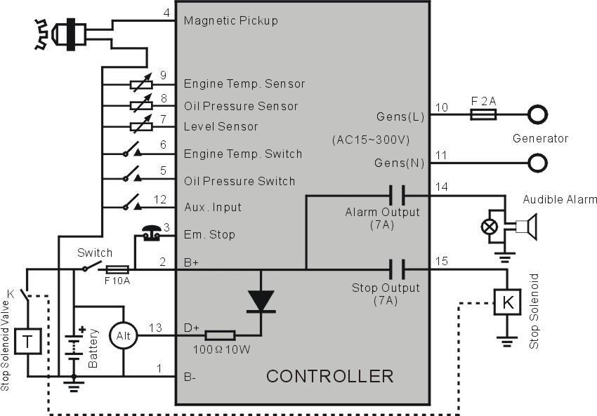
14 7. CONNECTIONS Terminal1 (B-): Connect to the negative of the start battery. Terminal 2 (B+): Connect to the positive of the start battery. Terminal 3 (Em. stop input): Emergency stop input (active when connect to B+), external connect to emergency shutdown normally closed button. Terminal 4 (Magnetic pickup): Magnetic pickup signal input, shielded wire is recommended. Connect to GND at one end only. Terminal 5 (Oil Pressure Switch): Low oil pressure input port, active when connected to B-. Terminal 6 (Engine Temp Switch): High water/cylinder temperature input port, active when connected to B-. Terminal 7 (Level Sensor): Liquid level sensor input, can connect fuel level sensor. Terminal 8 (Oil Pressure Sensor): Oil pressure sensor input port. Terminal 9 (Engine Temp. Sensor): High water/cylinder temperature sensor input port. Terminal 10 (L), 11 (N): External connect to generator voltage signal to judge successful start and provide over frequency protection. Terminal 12 (Aux. Input): Programmable digital input port, active when connected to B-. Terminal 13 (D+ Input): Connect to charging generator WL (or D+) terminals. Controller provides charge current. When the charger charging fails (D+ terminal voltage < 3V), charge alt fail alarm is sent. (Only warning and not shutdown) Terminal 14 (Alarm Output): Alarm output port (B+ voltage output). Contact capacity is 7A. Terminal 15 (Stop Output): ETS (energized to stop) output port (B+ voltage output). Contact capacity is 7A. PC configurable socket (LINK): Connect to SG72 module and PC via USB port for parameter setting.

15 8. CASE DIMENSIONS (Panel Cutout 78*66mm)
16 9. TYPICAL APPLICATION
HGM1780. Automatic Genset Controller USER MANUAL. Smartgen Technology
 HGM1780 Automatic Genset Controller USER MANUAL Smartgen Technology Smartgen Technology Co., Ltd No. 28 Jinsuo Road Zhengzhou Henan Province P. R. China Tel: 0086-371-67988888/67981888 0086-371-67991553/67992951
HGM1770 Automatic Generator Control Module OPERATING MANUAL Smartgen Electronic
 HGM1770 Automatic Generator Control Module OPERATING MANUAL Smartgen Electronic CONTENT 1. SUMMARY... 4 2. PERFORMANCE AND CHARACTERISTICS... 4 3. SPECIFICATIONS... 5 4. OPERATION... 6 5. PROTECTION...
HGM1780 AUTOMATIC GENERATOR MODULE CONTENT 1. SUMMARY PERFORMANCE AND CHARACTERISTICS SPECIFICATION OPERATION...
 CONTENT 1. SUMMARY...4 2. PERFORMANCE AND CHARACTERISTICS...4 3. SPECIFICATION...5 4. OPERATION...6 4.1. DISPLAY PANEL...6 4.2. LCD ICON INSTRUCTION...7 4.3. DISPLAY INSTRUCTIONS...7 4.4. DISPLAY DESCRIPTION...8
USER MANUAL ZHENGZHOU SMARTGEN TECHNOLOGY CO.,LTD
 HGM400 Series Genset Controller (HGM410/HGM420) USER MANUAL ZHENGZHOU SMARTGEN TECHNOLOGY CO.,LTD CONTENTS 1 OVERVIEW... 5 2 PERFORMANCE AND CHARACTERISTICS... 6 3 SPECIFICATION... 8 4 OPERATION... 9 4.1
HGM501 Gen-set Controller USER MANUAL. Smartgen Technology
 HGM501 Gen-set Controller USER MANUAL Smartgen Technology Contents 1. 2. 3. 4. 5. 6. 7. 8. 9. OVERVIEW... 4 PERFORMANCE AND CHARACTERISTICS... 4 TECHNICAL DATA... 5 OPERATION... 6 4.1. BUTTON DESCRIPTION...
HGM72 Automatic Generator Module OPERATING MANUAL Smartgen Electronic
 HGM72 Automatic Generator Module OPERATING MANUAL Smartgen Electronic CONTENT 1 SUMMARY... 4 2 FEATURES... 4 3 SPECIFICATION... 4 4 DISPLAY SYMBOL AND OPERATION... 5 5 ALARM... 7 6 PARAMETERS TABLE (ONLY
HGM7100N SERIES (HGM7110N/7120N) GENSET CONTROLLER USER MANUAL
 GENSET CONTROLLER USER MANUAL") HGM7100N SERIES (HGM7110N/7120N) GENSET CONTROLLER USER MANUAL SMARTGEN (ZHENGZHOU) TECHNOLOGY CO., LTD. Chinese trademark English trademark SmartGen make your generator smart SmartGen Technology Co.,
HGM7100N SERIES (HGM7110N/7120N) GENSET CONTROLLER USER MANUAL SMARTGEN (ZHENGZHOU) TECHNOLOGY CO., LTD. Chinese trademark English trademark SmartGen make your generator smart SmartGen Technology Co.,
HGM6100K Series Automatic Generator Module OPERATING MANUAL Smartgen Electronics
 HGM6100K Series Automatic Generator Module OPERATING MANUAL Smartgen Electronics All rights reserved. No part of this publication may be reproduced in any material form (including photocopying or storing
HSC940 Genset Controller CONTENTS 1 OVERVIEW PERFORMANCE AND CHARACTERISTICS SPECIFICATION OPERATION KEY FUNCTIONS...
 CONTENTS 1 OVERVIEW... 4 2 PERFORMANCE AND CHARACTERISTICS... 5 3 SPECIFICATION... 7 4 OPERATION... 8 4.1 KEY FUNCTIONS... 8 4.2 INDICATOR LIGHT... 9 4.3 AUTO START/STOP OPERATION... 10 4.4 MANUAL START/STOP
HGM6000K Series Automatic Generator Module OPERATING MANUAL Smartgen Electronic
 HGM6000K Series Automatic Generator Module OPERATING MANUAL Smartgen Electronic CONTENT 1 SUMMARY... 4 2 PERFORMANCE AND CHARACTERISTICS... 4 3 SPECIFICATION... 6 4 OPERATION... 6 4.1 KEY FUNCTION... 6
HGM72 Automatic Generator Module OPERATING MANUAL Smartgen Electronic
 HGM72 Automatic Generator Module OPERATING MANUAL Smartgen Electronic Smartgen Electronic Equipment Co., Ltd No.28 Jinsuo Road Zhengzhou Henan Province P.R.China Tel: 0086-371-67988888/67981888 0086-371-67991553/67992951/67992952
HGM6000K Series Automatic Generator Module USER MANUAL Smartgen Technology
 HGM6000K Series Automatic Generator Module USER MANUAL Smartgen Technology Chinese trademark English trademark Smartgen make your generator smart Smartgen Technology Co., Ltd. No. 28 Jinsuo Road Zhengzhou
HGM6100N SERIES (HGM6110N/6120N/6110NC/6120NC/6110CAN/6120CAN) GENSET CONTROLLER USER MANUAL SMARTGEN (ZHENGZHOU) TECHNOLOGY CO., LTD.
 GENSET CONTROLLER USER MANUAL SMARTGEN (ZHENGZHOU) TECHNOLOGY CO., LTD.") HGM6100N SERIES (HGM6110N/6120N/6110NC/6120NC/6110CAN/6120CAN) GENSET CONTROLLER USER MANUAL SMARTGEN (ZHENGZHOU) TECHNOLOGY CO., LTD. Chinese trademark English trademark SmartGen make your generator smart
HGM6100N SERIES (HGM6110N/6120N/6110NC/6120NC/6110CAN/6120CAN) GENSET CONTROLLER USER MANUAL SMARTGEN (ZHENGZHOU) TECHNOLOGY CO., LTD. Chinese trademark English trademark SmartGen make your generator smart
HGM6310D/6320D AUTOMATIC GENERATOR MODULE USER MANUAL
 HGM6310D/6320D AUTOMATIC GENERATOR MODULE USER MANUAL SMARTGEN ELECTRONIC CONTENT 1 SUMMARY... 4 2 PERFORMANCE AND CHARACTERISTICS... 4 3 SPECIFICATION... 6 4 OPERATION... 7 4.1 KEY FUNCTION... 7 4.2 AUTOMATIC
HGM6320T AUTOMATIC GENERATOR CONTROLLER USER MANUAL
 HGM6320T AUTOMATIC GENERATOR CONTROLLER USER MANUAL Smartgen Technology Smartgen Technology Co., Ltd No. 28 Jinsuo Road Zhengzhou Henan Province P. R. China Tel: 0086-371-67988888/67981888 0086-371-67991553/67992951/67992952
GENSET CONTROL MODULE
 HGM7200/HGM7100 Series AUTOMATIC GENSET CONTROL MODULE User Manual SMARTGEN TECHNOLOGY Smartgen Technology Co., Ltd No.28 Jinsuo Road Zhengzhou Henan Province P. R. China Tel: 0086-371-67988888/67981888
HGM6320T AUTOMATIC GENERATOR CONTROLLER USER MANUAL
 HGM6320T AUTOMATIC GENERATOR CONTROLLER USER MANUAL Smartgen Technology CONTENT 1 SUMMARY... 4 2 PERFORMANCE AND CHARACTERISTICS... 4 3 SPECIFICATION... 5 4 OPERATION... 6 4.1 LCD DISPLAY... 6 4.2 KEY
HGM6400 Automatic Genset Controller (With J1939 Interface) USER MANUAL Smartgen Technology
 USER MANUAL Smartgen Technology") HGM6400 Automatic Genset Controller (With J1939 Interface) USER MANUAL Smartgen Technology Chinese trademark English trademark Smartgen make your generator smart Smartgen Technology Co., Ltd No. 28 Jinsuo
HGM6400 Automatic Genset Controller (With J1939 Interface) USER MANUAL Smartgen Technology Chinese trademark English trademark Smartgen make your generator smart Smartgen Technology Co., Ltd No. 28 Jinsuo
HGM9520 Genset Parallel (With Mains) Unit USER MANUAL. Smartgen Technology
 Unit USER MANUAL. Smartgen Technology") USER MANUAL Smartgen Technology Chinese trademark English trademark Smartgen make your generator smart Smartgen Technology Co., Ltd. No. 28 Jinsuo Road Zhengzhou city Henan Province P. R. China Tel: +86-371-67988888/67981888
USER MANUAL Smartgen Technology Chinese trademark English trademark Smartgen make your generator smart Smartgen Technology Co., Ltd. No. 28 Jinsuo Road Zhengzhou city Henan Province P. R. China Tel: +86-371-67988888/67981888
HAT220A ATS CONTROLLER USERS MANUAL
 HAT220A ATS CONTROLLER USERS MANUAL Smartgen Technology Chinese trademark English trademark Smartgen make your generator smart Smartgen Technology Co., Ltd. No. 28 Jinsuo Road Zhengzhou Henan Province
DEEP SEA ELECTRONICS PLC
 COMPLEX SOLUTIONS MADE SIMPLE. DEEP SEA ELECTRONICS PLC DSE710 AUTOSTART CONTROL MODULE OPERATING MANUAL Deep Sea Electronics Plc Highfield House Hunmanby North Yorkshire YO14 0PH ENGLAND Sales Tel: +44
HGM9510 GENSET PARALLEL (WITH GENSET) UNIT USER MANUAL
 UNIT USER MANUAL") HGM9510 GENSET PARALLEL (WITH GENSET) UNIT USER MANUAL SMARTGEN (ZHENGZHOU) TECHNOLOGY CO.,LTD. Chinese trademark English trademark SmartGen make your generator smart SmartGen Technology Co., Ltd. No.
HGM9510 GENSET PARALLEL (WITH GENSET) UNIT USER MANUAL SMARTGEN (ZHENGZHOU) TECHNOLOGY CO.,LTD. Chinese trademark English trademark SmartGen make your generator smart SmartGen Technology Co., Ltd. No.
Deep Sea Electronics Plc
 Deep Sea Electronics Plc 5120 AUTOMATIC MAINS FAILURE MODULE OPERATING MANUAL Author: Anthony Manton Deep Sea Electronics Plc Highfield House Hunmanby North Yorkshire YO14 0PH England Tel: +44 (0) 1723
DKG-215 MANUAL AND REMOTE START UNIT
 DKG-215 MANUAL AND REMOTE START UNIT FEATURES Manual and remote starting and stopping Zero power consumption at rest Engine control mode available Generator protection Built in alarms and warnings 1 phase
DEEP SEA ELECTRONICS PLC
 COMPLEX SOLUTIONS MADE SIMPLE DEEP SEA ELECTRONICS PLC DSE720 AUTOSTART CONTROL MODULE OPERATING MANUAL http://bestgenerator.spb.ru/?page_id=6765 Deep Sea Electronics Plc Highfield House Hunmanby North
HGM7110DC DC Genset Controller USER MANUAL ZHENGZHOU SMARTGEN TECHNOLOGY CO.,LTD
 HGM7110DC DC Genset Controller USER MANUAL ZHENGZHOU SMARTGEN TECHNOLOGY CO.,LTD Chinese trademark English trademark Smartgen make your generator smart Smartgen Technology Co., Ltd. No. 28 Jinsuo Road
HGM6410/6420. Automatic Generator Module. With J1939 Interface OPERATING MANUAL. Smartgen Electronics
 HGM6410/6420 Automatic Generator Module With J1939 Interface OPERATING MANUAL Smartgen Electronics Smartgen Electronic Equipment Co,.Ltd No.12 Dongqing Street Zhengzhou Henan Province P.R.China Tel : (0086)-371-67992951
DEEP SEA ELECTRONICS PLC
 COMPLEX SOLUTIONS MADE SIMPLE. DEEP SEA ELECTRONICS PLC DSE5110 AUTOSTART CONTROL MODULE OPERATING MANUAL Deep Sea Electronics Plc Highfield House Hunmanby North Yorkshire YO14 0PH ENGLAND Sales Tel: +44
DKG-317 MANUAL AND REMOTE START UNIT
 Tel: +54-11-4629-600 Fax:+54-11-4627-3500 http://www.cramelectro.com DKG-317 MANUAL AND REMOTE START UNIT FEATURES Manual starting and stopping Engine control Generator protection Built in alarms and warnings
MODEL 520 REMOTE START ENGINE MANAGEMENT SYSTEM
 MODEL 520 REMOTE START ENGINE MANAGEMENT SYSTEM DSE 520 ISSUE 4 4/4/02 MR 1 TABLE OF CONTENTS Section Page INTRODUCTION... 4 CLARIFICATION OF NOTATION USED WITHIN THIS PUBLICATION.... 4 1. OPERATION...
DEEP SEA ELECTRONICS PLC
 DEEP SEA ELECTRONICS PLC 703 AUTOMATIC START MODULE OPERATING INSTRUCTIONS Author:- John Ruddock 703 Operating Instructions Issue Beta1 25/08/2003 2:45 PM JR - 1 - >
HGM6410/6420 AUTOMATIC GENERATOR MODULE WITH J1939 INTERFACE SOFTWARE MANUAL
 HGM6410/6420 AUTOMATIC GENERATOR MODULE WITH J1939 INTERFACE SOFTWARE MANUAL SMARTGEN ELECTRONICS Smartgen Electronic Equipment Co., Ltd No.12 Dongqing Street Zhengzhou Henan Province P.R.China Tel : (0086)-371-67992951
Generator Sets Controller 210. Operation Manual. Ver1.0
 Generator Sets Controller 210 Operation Manual Ver1.0 Note This information could include technical inaccuracies or typographical error. Manufacturer may make improvements and/or changes in the product(s)
DKG-207 AUTOMATIC MAINS FAILURE AND REMOTE START UNIT
 DKG-207 AUTOMATIC MAINS FAILURE AND REMOTE START UNIT FEATURES Automatic mains failure, Engine control, Gas engine support, Generator protection, Built in alarms and warnings, 3 phase mains voltage inputs
DEEP SEA ELECTRONICS PLC
 COMPLEX SOLUTIONS MADE SIMPLE DEEP SEA ELECTRONICS PLC DSE704 AUTOSTART CONTROL MODULE OPERATING MANUAL 057-042 704 Operating Instructions Issue 2.1 18/06/2007 11:27:00 JR - 1 - Deep Sea Electronics Plc
702 AUTOMATIC START MODULE OPERATING INSTRUCTIONS
 702 AUTOMATIC START MODULE OPERATING INSTRUCTIONS > TABLE OF CONTENTS 1 DESCRIPTION OF OPERATION... 4 1.1 MANUAL MODE OPERATION... 4 1.2 AUTOMATIC MODE OF OPERATION...
Flight Systems. Replacement for KASSEC DESCRIPTION
 DESCRIPTION The is a universal generator controller that will start, stop, and provide engine protection for most generators. Universal replacement for both the 90353 and 90354 KASSEC Compatible with most
DKG-114 MANUAL AND REMOTE START UNIT
 DKG-114 MANUAL AND REMOTE START UNIT FEATURES Both manual and remote controlled engine starting and stopping, Automatic shutdown on fault condition, Optional cooldown cycle on remote start operation, Optional
DKG-509 AUTOMATIC MAINS FAILURE UNIT
 DKG-509 AUTOMATIC MAINS FAILURE UNIT CANBUS AND MPU VERSIONS DESCRIPTION The controller is a comprehensive AMF unit for single genset standby or dual genset mutual standby operations. The unit is available
DKG-109 AUTOMATIC MAINS FAILURE UNIT
 Tel: +90-216-466 84 60 Fax: +90-216 364 65 65 datakom@datakom.com.tr http://www.datakom.com.tr DKG-109 AUTOMATIC MAINS FAILURE UNIT FEATURES Automatic mains failure Engine control Generator protection
Code: KOHLER KDI1903M MECC-ALTE ECP 28-M/4. VOLTAGE HZ PHASE COS Ø PRP kva/kw LTP kva/kw AMP. (LTP) 400/ ,8 18,9/15,2 20,8/16,6 30,07
 400/ ,8 18,9/15,2 20,8/16,6 30,07") Genset with manual control panel. Image for guidance purposes. PRP CONTINUOUS POWER: LTP 20 kva STANDBY POWER: 22 kva PRP Prime Power norma ISO 85281 LTP Limited Time Power norma ISO 85281 ENGINE ALTERNATOR
Genset with manual control panel. Image for guidance purposes. PRP CONTINUOUS POWER: LTP 20 kva STANDBY POWER: 22 kva PRP Prime Power norma ISO 85281 LTP Limited Time Power norma ISO 85281 ENGINE ALTERNATOR
DKG-109J AUTOMATIC MAINS FAILURE UNIT
 DKG-109J AUTOMATIC MAINS FAILURE UNIT CANBUS VERSION FEATURES True RMS measurements Automatic mains failure ECU control and monitoring through J1939 CAN J1939 ECU warnings displayed as text Various engine
DEEP SEA ELECTRONICS PLC
 COMPLEX SOLUTIONS MADE SIMPLE. DEEP SEA ELECTRONICS PLC DSE4120 AUTO MAINS FAILURE MODULE OPERATING MANUAL Deep Sea Electronics Plc Highfield House Hunmanby North Yorkshire YO14 0PH ENGLAND Sales Tel:
GCU-10. Automatic Engine Control Unit Operators Manual
 GCU-10 Automatic Engine Control Unit Operators Manual KUTAI ELECTRONICS INDUSTRY CO., LTD. TEL : +886-7-8121771 FAX : +886-7-8121775 Website : www.kutai.com.tw Headquarters : No.3, Lane 201, Chien Fu St.,
GENSET CONTROL MODULE A121A / A241A
 Technical Data Sheet GENSET CONTROL MODULE A121A / A241A Features: Models for both 12V and 24V systems. One model for both spark ignition and diesel engines. 4-alarm light outputs with lamp-test provisions.
5220 AUTOMATIC MAINS FAILURE MODULE OPERATING MANUAL
 5220 AUTOMATIC MAINS FAILURE MODULE OPERATING MANUAL > Section DSE Model 5220 Automatic Mains Failure & Instrumentation System Operators Manual TABLE OF CONTENTS
GSC300 Auto Start Engine Controller
 GSC300 Auto Start Engine Controller Revision 2.9 Installation and User Manual for the GSC300 Auto Start Engine Controller File: MAN-0039 R2.9, GSC300 User Manual.doc May 2011 2 of 29 Thank You For Purchasing
HAT700 Series HAT700/HAT700I/HAT700B/HAT700BI/HAT700S ATS CONTROLLER USER MANUAL
 HAT700 Series HAT700/HAT700I/HAT700B/HAT700BI/HAT700S ATS CONTROLLER USER MANUAL ZHENGZHOU SMARTGEN TECHNOLOGY CO.,LTD Software Version Version Date Note 1.0 2014-09-09 Original release. 1.1 2015-03-04
STANDARD OWNER S MANUAL
 WILLIE 1.0 STANDARD OWNER S MANUAL OPERATION, MAINTENANCE, & TROUBLESHOOTING STANDARD INSTRUCTIONS FOR ALL SYSTEMS DSE 3100 4/28/2011 Willis Power Systems 2950 N Martin Springfield, MO 65803 417.831.2520
Code: FPT F32AM1A MECC-ALTE ECP 28-VL / 4. VOLTAGE HZ PHASE COS Ø PRP kva/kw LTP kva/kw AMP. (LTP) 400/ ,8 30,0/24,0 32,5/26,0 46,97 ESPAÑA
 400/ ,8 30,0/24,0 32,5/26,0 46,97 ESPAÑA") Genset with manual control panel. Image for guidance purposes. PRP CONTINUOUS POWER: LTP 30 kva STAND-BY POWER: 33 kva PRP Prime Power norma ISO 8528-1 LTP Limited Time Power norma ISO 8528-1 ENGINE ALTERNATOR
Genset with manual control panel. Image for guidance purposes. PRP CONTINUOUS POWER: LTP 30 kva STAND-BY POWER: 33 kva PRP Prime Power norma ISO 8528-1 LTP Limited Time Power norma ISO 8528-1 ENGINE ALTERNATOR
EPM72 Engine Protection Module
 Capricorn Controls DA01EPM1-1 Data & Application Note Page 1 of 8 EPM2 Engine Protection Module Genset Controls - Timers - Monitors - Trips - Battery Charging - Spares & Accessories - Custom Products All
GSC300 Auto Start Engine Controller
 GSC300 Auto Start Engine Controller Revision 2.12 Installation and User Manual for the GSC300 Auto Start Engine Controller File: MAN-0039 R2.12, GSC300 User Manual.doc June 2014 2 of 28 Thank You For Purchasing
Code: VOLVO TAD 731 GE MECC-ALTE ECP 34-2L/4. VOLTAGE HZ PHASE COS Ø PRP kva/kw LTP kva/kw AMP. (LTP) 400/ ,8 150,0/120,0 165,0/132,0 238,44
 400/ ,8 150,0/120,0 165,0/132,0 238,44") Genset with manual control panel. Image for guidance purposes. PRP CONTINUOUS POWER: LTP 150 kva STAND-BY POWER: 165 kva PRP Prime Power norma ISO 8528-1 LTP Limited Time Power norma ISO 8528-1 ENGINE
Genset with manual control panel. Image for guidance purposes. PRP CONTINUOUS POWER: LTP 150 kva STAND-BY POWER: 165 kva PRP Prime Power norma ISO 8528-1 LTP Limited Time Power norma ISO 8528-1 ENGINE
TG350 User Manual. Manual Revision: Min. FW Revision: Date Released: 09/01/ DYNAGEN Technologies Inc
 TG350 User Manual Manual Revision: 1.4.0 Min. FW Revision: 1.42.01 Date Released: 09/01/2014 Table of Contents 1 Introduction 1.1 Specifications... 3 2 Installation 2.1 Terminal s... 6 2.2 Typical Wiring...
PPU Diesel Power 50/60Hz Containerized Generator Set
 50Hz at 0.8 Power Factor 380-400V 3-Phase Rated Voltage 60Hz at 0.8 Power Factor 480V 3-Phase Rated Voltage PRIME STANDBY 800kW/1,000kVA 880kW/1,100kVA GENERATOR SET PERFORMANCE Application A factory designed
OPERATING INSTRUCTIONS ECON-M
 OPERATING INSTRUCTIONS ECON-M INDEX 1.0 Introduction 2.0 Salient features, Protection & Supervision 3.0 Display/ Front Panel 4.0 Switches Description 5.0 LED Annunciations Description 6.0 Lamp Test 7.0
DKG-707 MULTI GENSET PARALLELLING UNIT WITH J1939 INTERFACE
 DKG-707 MULTI GENSET PARALLELLING UNIT WITH J1939 INTERFACE STANDARD FEATURES Automatic and manual start Multi genset synchronization (up to 8 gensets) Multi genset load sharing (up to 8 gensets) Both
GENSET CONTROL MODULE A121H / A241H. User selectable time delays for engine start and engine stop (cool down).
.") Technical Data Sheet GENSET CONTROL MODULE A121H / A241H Features: Models for both 12V and 24V systems. One model for both spark ignition and diesel engines. 4-alarm light outputs with lamp-test provisions.
Technical Data Sheet GENSET CONTROL MODULE A121H / A241H Features: Models for both 12V and 24V systems. One model for both spark ignition and diesel engines. 4-alarm light outputs with lamp-test provisions.
Engine Model: 4B3.9-G1 Engine Technical Data No. of Cylinders / Alignment: Cycle: 4 / In Line 4 Stroke Bore / Stroke: mm 102/120 Induction: Cooling Me
 WGP-C30/S CUMMINS Series Rotate speed governor: Mechanical governor Excitation system: Self excited, SHUNT A.V.R model: AS480 Emergency stop switch ATS (automatic transfer switch) receptacle 1x12V sealed
VC-4820 Programmable DC-DC Converter with Battery Charger function USER'S MANUAL
 1. INTRODUCTION VC-4820 Programmable DC-DC Converter with Battery Charger function USER'S MANUAL This MCU controlled Step Down DC-DC Converter has a digitally adjustable output in 0.2V increments. This
GENSET CONTROL MODULE LEVEL 1 A121CM / A241CM. Special logic to re-establish cranking following a false start.
 Technical Data Sheet GENSET CONTROL MODULE LEVEL 1 A121CM / A241CM Features: Models for both 12V and 24V systems. One model for both spark ignition and diesel engines. 5-alarm light outputs with lamp-test
DKG-705 AUTOMATIC MAINS FAILURE AND REMOTE START UNIT WITH PARALLEL TO MAINS AND DUAL GENSET PARALLEL FEATURES
 Genset Automation Control Pte Ltd DKG-705 AUTOMATIC MAINS FAILURE AND REMOTE START UNIT WITH PARALLEL TO MAINS AND DUAL GENSET PARALLEL FEATURES FEATURES Automatic mains failure, Remote start operation,
Code: DEUTZ BF4M 1013 FC MECC-ALTE ECP 34-1L/4. VOLTAGE HZ PHASE COS Ø PRP kva/kw LTP kva/kw AMP. (LTP)
") Genset with manual control panel. Image for guidance purposes. PRP CONTINUOUS POWER: LTP 130 kva STAND-BY POWER: 145 kva PRP Prime Power norma ISO 8528-1 LTP Limited Time Power norma ISO 8528-1 ENGINE
Genset with manual control panel. Image for guidance purposes. PRP CONTINUOUS POWER: LTP 130 kva STAND-BY POWER: 145 kva PRP Prime Power norma ISO 8528-1 LTP Limited Time Power norma ISO 8528-1 ENGINE
ECU-02 Ver2.1 Automatic Engine Control Unit Operators Manual
 ECU-02 Ver2.1 Automatic Engine Control Unit Operators Manual Headquarters : No.3, Lane 201, Chien Fu St., Chyan Jenn Dist., Kaohsiung, TAIWAN Tel : + 886-7-8121771 Fax : + 886-7-8121775 URL : http://www.kutai.com.tw
DSEULTRA DSE6000 Quick Start Guide Document Number
 n DSEULTRA DSE6000 Quick Start Guide Document Number 057-102 Author : John Ruddock Deep Sea Electronics Plc Highfield House Hunmanby North Yorkshire YO14 0PH ENGLAND Sales Tel: +44 (0) 1723 890099 Sales
PowerView PV380-R2 Mechanical Configuration
 PowerView PV380-R2 Mechanical Configuration Operations Manual *Products covered in this document comply with European Council electromagnetic compatibility directive 2004/108/EC and electrical safety directive
DEEP SEA ELECTRONICS PLC
 COMPLEX SOLUTIONS MADE SIMPLE. DEEP SEA ELECTRONICS PLC DSE5220 AUTO MAINS FAILURE MODULE OPERATING MANUAL Deep Sea Electronics Plc Highfield House Hunmanby North Yorkshire YO14 0PH ENGLAND Sales Tel:
Deep Sea Electronics Plc
 Deep Sea Electronics Plc 550 Operators Manual Author Miles Revell Deep Sea Electronics Plc Highfield House Hunmanby Industrial Estate North Yorkshire YO14 0PH ENGLAND Tel +44 (0) 1723 890099 Fax +44 (0)
Code: KOHLER KDW 1404 ZANARDI ATO 28-1VS/4. VOLTAGE HZ PHASE COS Ø PRP kva/kw LTP kva/kw AMP. (LTP) 400/ ,8 10,0/8,0 11,0/8,8 15,9
 400/ ,8 10,0/8,0 11,0/8,8 15,9") Automatic without ats panel Standby Genset V3. Image for guidance purposes. PRP CONTINUOUS POWER: LTP 10 kva STANDBY POWER: 11 kva PRP Prime Power norma ISO 85281 LTP Limited Time Power norma ISO 85281
Automatic without ats panel Standby Genset V3. Image for guidance purposes. PRP CONTINUOUS POWER: LTP 10 kva STANDBY POWER: 11 kva PRP Prime Power norma ISO 85281 LTP Limited Time Power norma ISO 85281
DEEP SEA ELECTRONICS PLC DSE3210 CONTROLLER OPERATORS MANUAL
 DEEP SEA ELECTRONICS PLC DSE3210 CONTROLLER OPERATORS MANUAL Document number 057-153 Author: Allan Jones DSE3210 Operators Manual Issue 1 http://bestgenerator.spb.ru/?page_id=6765 Deep Sea Electronics
DGC-2020 DIGITAL GENSET CONTROLLER
 DIGITAL GENSET CONTROLLER Basler Electric s Digital Genset Controller (DGC-2020) is a highly advanced integrated genset control system. The DGC-2020 is perfectly focused, combining rugged construction
USER MANUAL FOR GC500 GENSET CONTROLLER SEDEMAC ABSTRACT
 ABSTRACT This manual is intended as an information guide for operating SEDEMAC's GC500 genset controller. USER MANUAL FOR Doc #SED-MAN-GC500-002 Date: 01-Aug-2016 GC500 GENSET CONTROLLER Product Manual
Auto Mains Failure AMF Controller AE10113
 Auto Mains Failure AMF Controller AE03 Auto Mains Failure DESCRIPTION AMF Controller AE03 is an Automatic Mains Failure controller, which activates the generator during power failure & vice versa. The
AMF+ATS CONTROL PANEL
 AMF+ATS CONTROL PANEL SELECTION INSTRUCTION Smartgen Technology Chinese trademark English trademark Smartgen make your generator smart Smartgen Technology Co., Ltd. No.28 Jinsuo Road Zhengzhou City Henan
TE2010-GE Instructions manual
 TE2010-GE Instructions manual Hardware: 3.1-4.0 Software: 3.7 PREFACE Thanking you for preference, TECNOELETTRA SRL hopes that the use of this equipment could be a reason of satisfaction. This manual is
AUTOSTART 705S V1.00 AUTOSTART 710S / 720S / 730S V1.04 Programming Reference and Check Sheets
 The Generator Controls Division of Frank W. Murphy AUTOSTART 705S V1.00 AUTOSTART 710S / 720S / 730S V1.04 Programming Reference and Check Sheets MODEX AUTOMATION FRANK W. MURPHY LTD. Church Road Laverstock
Deep Sea Electronics Plc
 Deep Sea Electronics Plc 5520 Operators Manual Author Tony Manton Deep Sea Electronics Plc Highfield House Hunmanby Industrial Estate North Yorkshire YO14 0PH ENGLAND Tel +44 (0) 1723 890099 Fax +44 (0)
Annex A TECHNICAL SPECIFICATION FOR SUPPLY, INSTALLATION, TESTING AND COMMISSIONING OF 400V (750KVA) DIESEL
 DIESEL") Annex A TECHNICAL SPECIFICATION FOR SUPPLY, INSTALLATION, TESTING AND COMMISSIONING OF 400V (750KVA) DIESEL 1 TECHNICAL SPECIFICATION FOR 400V, 750 kva D.G. SET 1.0 SCOPE This specification covers the
Annex A TECHNICAL SPECIFICATION FOR SUPPLY, INSTALLATION, TESTING AND COMMISSIONING OF 400V (750KVA) DIESEL 1 TECHNICAL SPECIFICATION FOR 400V, 750 kva D.G. SET 1.0 SCOPE This specification covers the
DEEP SEA ELECTRONICS PLC DSEE100 Operator Manual
 DEEP SEA ELECTRONICS PLC DSEE100 Operator Manual Document Number: 057-273 Author: Fady Atallah 057-273 ISSUE: 2 DSEE100 Operator Manual Deep Sea Electronics Plc Highfield House Hunmanby North Yorkshire
MB A 12V/24V DC PROGRAMMABLE DUAL BATTERY ISOLATOR
 MB-3688 120A 12V/24V DC PROGRAMMABLE DUAL BATTERY ISOLATOR User Manual Warning and Precautions MB-3688 is built with corrosion resistant material and the main electronic assembly is well sealed inside
The measurements module provides the following engine features information:
 1. INTRODUCTION The CEM6 control board is a monitoring network signal and monitoring and control generator feeding device. The device consists of 2 different modules: - Visualization module. The visualization
PSM72H Push-Button Start Module
 Capricorn Controls DA02PSM72H1-2 Data & Application Note Page 1 of 6 PSM72H Push-Button Start Module Genset Controls - Timers/Monitors/Trips - Battery Charging Spares & Accessories - Custom Products Ultra
ICON 2 1. FEATURES AND CHARACTEIRICS
 ICON 2 1. FEATURES AND CHARACTEIRICS High end Micro-controller(DSP) technology Wide range of auxiliary supply: 7V to 45Vdc. Low power Consumption : 200 ma @ 12 V DC. Alphanumeric 16X4 or 16X2 LCD display
GENSET PRODUCTS 013 2
 GENSET PRODUCTS 2013 TECHNOLOGY IS NOW FOR EVERYONE D 700 COMMUNICATION CAPABILITIES AUTOMATIC MAINS FAILURE UNITS DKG 107 DKG 107 The lowest cost AMF module Factory set timers Adjustable AC low voltage
Code: VOLVO TAD 734 GE MECC-ALTE ECO 38-1LN. VOLTAGE HZ PHASE COS Ø PRP kva/kw LTP kva/kw AMP. (LTP) 400/ ,8 250,0/200,0 275,0/220,0 397,4
 400/ ,8 250,0/200,0 275,0/220,0 397,4") Automatic with amf/ats panel Stand-by Genset V2. Image for guidance purposes. PRP CONTINUOUS POWER: LTP 250 kva STAND-BY POWER: 275 kva PRP Prime Power norma ISO 8528-1 LTP Limited Time Power norma ISO
Automatic with amf/ats panel Stand-by Genset V2. Image for guidance purposes. PRP CONTINUOUS POWER: LTP 250 kva STAND-BY POWER: 275 kva PRP Prime Power norma ISO 8528-1 LTP Limited Time Power norma ISO
1 / Genset general description
 Measures: L : 3950 mm H : 2400 mm W: 1550 mm H Weight: 4600kg W L Hz 50 Hz V 400/230 V Water cooled Diesel 1500 r.p.m Open skid Illustrative image. CE Conformity 1 / Genset general description Engine Alternator
Observe all necessary safety precautions when controlling the soft starter remotely. Alert personnel that machinery may start without warning.
 Introduction OPERATING INSTRUCTIONS: MCD REMOTE OPERATOR Order Codes: 175G94 (for MCD 2) 175G361 + 175G9 (for MCD 5) 175G361 (for MCD 3) 1. Introduction 1.1. Important User Information Observe all necessary
MD10. Engine Controller. Installation and User Manual for the MD10 Engine Controller. Full Version
 MD10 Engine Controller Installation and User Manual for the MD10 Engine Controller. Full Version File: MartinMD10rev1.4.doc May 16, 2002 2 READ MANUAL BEFORE INSTALLING UNIT Receipt of shipment and warranty
The monitor can be placed on the dashboard, on the sun visor or mounted in any convenient place in the vehicle.
 1 Introduction Congratulations on purchasing the new TYREGUARD 400 - TYRE PRESSURE MONITORING SYSTEM (TPMS). This system is a safety system for monitoring vehicle s tyre air pressure and temperature. It
USERS MANUAL MCD REMOTE OPERATOR
 USERS MANUAL MCD REMOTE OPERATOR Order Code: 175G9004, 175G3061 Contents Contents Introduction...2 Important User Information...2 General Description...2 Symbols Used in this Manual...2 Installation...3
GENSET CONTROL MODULE LEVEL 0 A120A. User selectable time delays for engine start and engine stop (cool down).
.") Technical Data Sheet GENSET CONTROL MODULE LEVEL 0 A120A Features: One model for both spark ignition and diesel engines. 4-alarm light outputs with automatic lamp-test provision. Overspeed adjustment not
Technical Data Sheet GENSET CONTROL MODULE LEVEL 0 A120A Features: One model for both spark ignition and diesel engines. 4-alarm light outputs with automatic lamp-test provision. Overspeed adjustment not
TG350 User Manual. Manual Revision: Min. FW Revision: Date Released: 18/12/ DynaGen Technologies Inc
 TG350 User Manual Manual Revision: 6.0.0 Min. FW Revision: 1.82.09 Date Released: 18/12/2017 TG350 User Manual Table of Contents User Guide 1 Introduction 4... 4 1.1 Specifications 2 Installation 6...
LSP88S3. Powered by 50HZ. Water-cooled. Three Phase. Diesel KVA 88 KW 70. Standby Power
 LSP88S3 Powered by 50HZ Water-cooled Three Phase Diesel Model LSP88S3 Standby Power KVA 88 KW 70 Prime Power KVA 80 KW 64 Frequency Hz 50 Voltage V 230/400 Rated speed rpm 1500 Perkins is one of the largest
PREMIER POWER PACK INSTRUCTION MANUAL EN54-4 POWER SUPPLY UNIT INSTRUCTION MANUAL. GLT.MAN-138 Issue: /05/2016 N.R.P.J.
 EN54-4 POWER SUPPLY UNIT INSTRUCTION MANUAL GLT.MAN-138 CONTENTS Introduction to the Premier Power Pack PSU... 2 Changes to EN54-4 (The Fire Alarm Equipment Power Supply Standard)... 3 Indications... 4
REVISED ATM72 Auto Transfer Module
 Capricorn Controls DA01ATM1-1 Data & Application Note Page 1 of 8 REVISED - - - ATM72 Auto Transfer Module Genset Controls - Timers - Monitors - Trips - Battery Charging - Spares & Accessories - Custom
Transfer switch GTEC open or delayed transition
 Transfer switch GTEC open or delayed transition 40-1250 Amp Description The GTEC automatic transfer switch combines reliability and flexibility in a small, economical package for transferring loads between
WPS350/S EP Series. Features:
 Features: Rotate speed governor: Electronic Excitation system: self-excited, SHUNT A.V.R model: R250/R450 Emergency stop switch ATS (automatic transfer switch) receptacle 2x12V sealed for life maintenance
Energy Division
 Energy Division http://energy.tycoelectronics.com Installation and Operating Manual GEN-TRANS Automatic Generator Transfer Switch Controller with Metering Tyco Electronics UK Limited Crompton Instruments
ALC-PRM-VFC. Ceiling Mounted Photocell. Product Guide. Overview. Features
 Product Guide ALC-PRM-VFC Ceiling Mounted Photocell Overview The ALC-PRM-VFC photocell will turn lighting on when the ambient light falls below a preset level. The lighting will then be turned off when
EG1299. Variable Speed Engine Controller for Telecom Backup Gensets SEDEMAC EG1299 HIGHLIGHTS
 EG1299 Variable Speed Engine Controller for Telecom Backup Gensets HIGHLIGHTS Built-in electronic governor module Variable and fixed speed operation Configurable 0% droop with paralleling support RS485