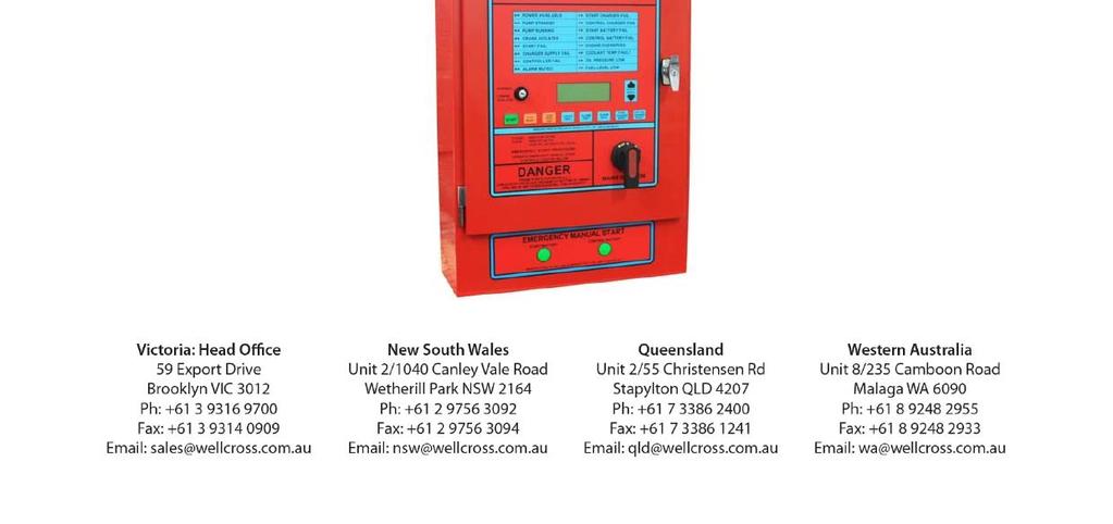
-2- Designed to automatically operate a diesel fire pump engine when the contacts of a remote water pressure switch close.
|
|
|
- Gwendolyn Carr
- 5 years ago
- Views:
Transcription

1 -1-1
2 -2- FUNCTION Designed to automatically operate a diesel fire pump engine when the contacts of a remote water pressure switch close. POWER SUPPLY: 240V A.C single phase supply and 12 or 24 V D.C. INDICATORS: Power available (green) - Mains power available. Pump standby (green - Operational and without major faults. Pump running (red) - Pump is running. Crank isolated (red) - Isolates controller auto starting (see crank isolate switch below. Start fail (red) - Diesel engine has failed to start when requested. Charger supply fail (red) - Battery charger power supply failed. Controller fail (red) - Controller has failed. Alarm muted (red) - Audible alarm is muted. Start charger fail (red) - Start battery charger is faulty. Control charger fail (red) - Control battery charger is faulty Start battery fail (red) - Start battery volts is/was below the preset low level Control battery fail (red) - Control battery volts is/was below the preset low level. Engine overspeed (red) - Pump speed is/was in excess of preset limit. Coolant temp fault (red) - Engine coolant temp is exceedingly high or low (if low temp, alarm optioned flash fast) Oil pressure low (red) - Oil pressure is/was below preset. Fuel level low (red) - Fuel level in tank is/was low. BUTTONS: Display scroll - Scrolls the displayed screen. Start - Push to manually start the engine. Stop - Push to stop the engine and clear alarm conditions. Light test - Illuminates all indicator lights Alarm test - Tests the alarm bell and light Alarm mute - Silences the audible alarm bell. Mute will be reset when the alarm condition stops, or alarm test is pressed. Start charger boost - Push to boost the charge rate on the control battery. Charging turns off automatically. Crank isolate - Isolates the pump preventing cranking from the controller. Engine can still be cranked from the emergency manual start solenoid buttons located below the controller fascia. Over speed test- simulates over speed test when engine is running. OPERATION: Starting - System is designed to automatically start the engine by closing a remote pressure switch. System may be test run by pressing the start button on the controller fascia. Stopping - Push controller stop/reset button. 1.1

3 - EMERGENCY STARTING: JOCKEY PUMP: Emergency manual start buttons - located below the controller fascia on the fire pump controller. Press either solenoid button to crank the engine from the start or control battery, external to the controller circuitry. If fitted, automatically maintains water pressure in system pipe work. AUTO button - Automatically starts and stops the jockey pump upon the closure or opening of a remote located jockey pressure switch. JOCKEY PUMP ISOLATE button - Jockey pump will not operate. MANUAL button - Allows the Jockey pump to run continuously whilst pressed. INTRODUCTION This controller is a dedicated microprocessor that operates in a similar fashion to an IBM or Macintosh Computer. It has specific input, output and display capabilities that have been designed to meet all the requirements of AS (The Australian Fire Pump Standard). AS2941 REQUIREMENTS A fire pump controller must start the diesel engine driving a fire pump in response to an external start signal, usually a pressure switch that is plumbed into the fire service ring main. Once started the engine must continue to run until it is manually stopped or runs out of fuel. In the event of an engine not starting immediately it must be cranked for 15 seconds followed by a pause in cranking of 15 seconds. This cycle must be repeated 6 times or until the engine starts. 1.2
4 -4- CONTROL SWITCHES CRANK ISOLATE SWITCH A two position rotary key lockable switch located to the left of the liquid crystal display. In the isolate position the engine cranking circuits are disconnected from the controller. Automatic pressure switch starting and controller manual starting are disabled. This switch position will allow routine maintenance to be undertaken without concern about the engine starting. In the normal position the controller will crank the engine whenever an external start signal is present or when the controller start button is pressed. Note that turning this switch to the isolate position will cause the controller to generate an alarm condition. When this switch is in the isolate position the engine can still be started using the emergency manual start buttons located adjacent to the controller. CONTROL BUTTONS DISPLAY SCROLL BUTTONS Two buttons located to the right of the liquid crystal display. Many sorts of information can be displayed on the liquid crystal; theses buttons allow an operator to scroll through display items to get to specific required information. You may scroll up or down to get to the required information. 1.3
5 -5- Push the arrow to scroll AS2941 Diesel Fire Pump Controller Serial # Software REV: Engine Speed RPM Hours Run :--:-- Engine Alternator - Amps DC Fuel Remaining --- % Coolant Temperature -- C --- KPA Control Battery --.- Volts DC Control Charge Rate -.- Amps DC Start Battery --.- Volts DC Start Charge Rate -.- Amps DC The position at which scrolling is stopped is not relevant to controller operation. 1.4

 the engine will not stop. The stop button also functions as a reset on any latched alarm information i.e. Charger Supply Fail or Oil Pressure Low.")
6 -6- START BUTTON Allows an operator to test start the fire pump engine in order to carry out routine maintenance. It can also be used to start the engine if external start signals have failed or are not present. Note: that the crank isolate key switch must be in the normal position for the start button to operate. STOP / RESET BUTTON When pressed will send a stop signal to the engine fuel stop solenoid. Note: if an external start signal is present (pump on call) the engine will not stop. The stop button also functions as a reset on any latched alarm information i.e. Charger Supply Fail or Oil Pressure Low. Note: if alarm condition is still present then stop /reset button cannot clear the alarm indication. LIGHTS TEST BUTTON Will cause all 32 alarm and status light emitting diodes to illuminate. It is provided as a test for indicator failure. ALARM TEST BUTTON When pressed will test the external alarm bell if connected to the controller bell circuit. It will also test the flashing alarm light or strobe if connected to the controller visible alarm circuit. ALARM MUTE BUTTON When pressed will mute the alarm bell if it is currently operating. The alarm cause will continue to be indicated by the alarm and status LED s. Alarm mute will automatically cancel when all alarm causes are cleared or reset. When an alarm condition is muted a further alarm condition will not cause the bell to operate. Note: that the flashing light or strobe is not turned off when alarm mute is pressed. START CHARGER BOOST BUTTON The battery chargers are current limited constant potential type that will maintain an optimum charge level in each set of batteries. Chargers will turn on at maximum charge rate when battery voltage has fallen to nominal voltage plus.75v. Charger will turn off completely when battery voltage has risen to nominal voltage plus approximately 2.5V. 1.5
7 -7- Note: That the chargers are not a trickle charger and must have a battery connected for correct operation. When the boost button is pressed the charger will turn on at maximum charge rate, charging the battery up to the high charge turn off point. CONTROL CHARGER BOOST BUTTON As for start charger boost button. Two light emitting decodes are provided to indicate each function. OVER SPEED TEST BUTTON When diesel engine is running press button to simulate an over speed. Engine will stop and indicate over speed. To reset press stop reset button. POWER AVAILABLE These green LED s should be continuously lit and indicate the presence of the AC supply. CONTROL INDICATORS PUMP STANDBY These green LED s should be continuously lit and indicate a normal standby situation. If they are not lit check - Is crank isolate switch in normal position? - Fuel level? - Battery voltages? - Engine temperatures low? - Or any other fault indicators? PUMP RUNNING Will indicate when the pump is running at rated speed. CRANK ISOLATED Will indicate that the crank isolate key switch is not in the normal position. 1.6
8 -8- START FAIL Will indicate that the diesel engine has not started after completing 6 crank cycles. This indicator will flash if alarm cause has occurred but is no longer present. Cancel flashing by pressing STOP/RESET. CHARGER SUPPLY FAIL Indicates failure of the AC to battery chargers. When supply fail LED s are lit the green power available LED s must be off. FUEL LEVEL LOW Indicates when fuel tank level is low. This level is adjustable with a factory setting of 75%. Flashing LED s indicate that fuel level was low and is now normal. Pressing the STOP/RESET button will cancel the flashing. ALARM MUTED Indicates that an alarm condition exists and the alarm mute button has been pressed. The LED s will turn off automatically when the alarm condition ceases. START CHARGER FAIL Indicates when the battery should be charging but is not. CONTROL CHARGER FAIL Refer to above. START BATTERY FAIL Indicates when start battery voltage has fallen to an unacceptable low level. This level is adjustable, with a factory setting of 12 / 24 volts. Flashing LED s indicate that start battery voltage was unacceptably low and is now normal. Pressing the stop/reset button will cancel the flashing. Although the controller can deem a start battery as "failed" it may continue to attempt starting. 1.7
9 -9- CONTROL BATTERY FAIL Refer to above. ENGINE OVERSPEED Indicates when diesel engine speed exceeds programmed set point, this level is adjustable. An over speed alarm status will display then the engine will stop. If this condition occurs during routine testing, check program settings or call a service technician. This indicator will flash if alarm cause has occurred but is no longer present. Cancel flashing by pressing STOP/RESET. COOLANT TEMPERATURE FAULT Indicates when the diesel engine coolant temperature exceeds that s recommended by the engine manufacturer. This level is adjustable with a factory setting of 95 C. Although a Coolant Temperature High alarm may be displayed the engine is not stopped. If this condition occurs during routine testing the engine should be immediately stopped and attended to by a competent mechanic. For engines fitted with a water jacket heater; failure of which could prevent engine starting; a low temperature alarm can be indicated. This condition will be indicated by the "Coolant Temperature High" LED s flashing at a fast rate. The engine should be attended to immediately by a competent mechanic. This indicator will flash if alarm cause has occurred but is no longer present. Cancel flashing by pressing STOP/RESET. OIL PRESSURE LOW Indicates when the diesel engine lubricating oil pressure is less than that recommended by the engine manufacturer. This level is adjustable with a factory setting of 50KPA. Although an oil pressure low alarm status may be displayed, the engine is not stopped. If this condition occurs during routine testing the engine should be immediately stopped and attended to by a competent mechanic. This indicator will flash if alarm cause has occurred but is no longer present. Cancel flashing by pressing STOP/RESET. 1.8
10 CONTROLLER FAIL Indicates if the microprocessor stops operating. Detected by Hard Wired circuitry outside of the microprocessor. This alarm status may or may not indicate that the controller is unable to start the diesel engine in a fire situation. However competent technicians should attend to this situation at the earliest possibility. VOLT FREE CONTACTS Are rated for a maximum current of AC1 and a maximum voltage of 32VDC. If these ratings are exceeded, even for the shortest possible time, permanent damage may result, causing the controller to be unable to start the engine. CONTROLLER SERVICEABLE (NC-200; COM-201; NO-202) Is normally energised and changes to the state indicated on the drawings for microprocessor failure. Competent technicians should attend to this situation at the earliest possible. Note: that both batteries flat or disconnected will also cause this condition. COMMON ALARM (NC-212; COM-213; NO-214) Will energise when all systems are normal and controller / engine are ready to start in a fire situation. OVERSPEED (NC-221; COM-222; NO-223) Will energise when low battery volts on start and control condition exists, or has existed. Note: that engine fault does not necessarily mean the engine has stopped. FUEL LEVEL LOW (NC-218; COM-219; NO-220) Will energise for low fuel level. Note: that if both batteries fail or are disconnected the microprocessor will eventually stop and this alarm will disappear. PUMP RUNNING (NC-203; COM-204; NO-205) Will energise when diesel engine is at a speed higher than starter motor cut out speed. 1.9
 Will energise when the battery charger AC supply has failed.")
11 FAIL TO START (NC-206; COM-207; NO-208) Will energise when the engine has been told by the control panel to start and has not. This contact is most suited when a pump fail contact is required to drive external circuitry. CHARGER SUPPLY FAIL (NC-209; COM-210; NO-211) Will energise when the battery charger AC supply has failed. Power is continually being consumed by the controller and under normal conditions this power is being replaced by the battery chargers. If a charger supply failure condition exists for 24 hours the power consumed by the controller will cause batteries to go flat. Attention from competent personnel should happen at the earliest possible time. If competent repair people are not available, isolate AC supply and disconnect both batteries. Notification to Local Fire Authorities and continual supervision should occur until all systems are back to normal. START / CRANK ISOLATE (NC-215; COM-216; NO-217) Energises when crank isolating switch is in ISOLATE position. INSTALLATION The controller should be mounted in a position away from vibration, heat and hot exhaust pipes and potential diesel fuel and water spills. If located outdoors considerations must be given to a sun shade. Direct sunlight combined with high ambient temperatures will cause controller failure. Note: that PVC insulated engine and control wiring will also fail if continually subjected to UV radiation (i.e. sunlight). The controller is certified to IP54 AS 1939 and has a "Lexan" membrane fascia. Continual UV radiation on fascia will cause permanent damage and possibly controller failure. Controller should be wired to solenoid panel, engine, external start signal and alarm circuits. Using the schematic drawings and termination diagrams supplied with the controller. Note: that even though the controller has fuses and reverse polarity protection, various components of the controller can suffer permanent damage if incorrectly connected. 1.10


12 Before connecting AC supply or batteries, double check all wiring and stated voltage rating which will be on a Silver or White /Black ID Sticker located on inside of controller door. TESTING Turn crank isolate switch to "isolate" position. Verify that engine is okay to run; fuel; lube oil; coolant etc. Connect control battery, ensure correct polarity. Controller will take a few seconds to initialize and will then display serial no. and software revision. Controller may also be indicating error conditions. Scroll up twice. Display will show control battery voltage and charge rate. Charge rate will be 0.0 Amps DC as AC supply not yet connected. Scroll down once. Display will show start battery voltage and charge rate. Both should be zero. Connect start battery - ensure correct polarity. Display should show start battery voltage. Leaving crank isolate switch in "isolate" position; scroll up & down, press a few buttons to get a "feel" for what s happening. Apply AC supply to controller. Battery charge rate should now be about 3 AMPS DC. If display shows 0.0 AMPS DC momentarily press the appropriate charger boost button; correct charge rate should now be displayed. 1.11
13 FUSES Fuses are fitted to several of the cards fitted to the controller. They have been fitted to protect the controller components from abnormal load conditions and unusual transients. If a fuse "blows" replace only with size and rating specified. Fitting larger fuses than that specified will eventually lead to permanent irreplaceable damage to controller and/or components. Before replacing fuses or removing plug in cards, turn off AC supply and disconnect batteries. ENGINE CONTROLLER CARD (207206) F1 F2 F3 F4 12/24V Crank Fuse 30A Blade Automotive 12/24V Stop Solenoid Fuse 30A Blade Automotive 12/24V Regulator Fuse 30A Blade Automotive 12/24V NFPA 20 Crank Fuse 30A Blade Automotive POWER SUPPLY CARD (207207) F1 F2 F3 F4 F5 Control Battery 5A Blade Automotive Start Battery 5A Blade Automotive AC Mains Supply 5A Automotive Control Transformer Secondary 5A Blade Automotive Auxiliary Supply 5A Blade Automotive BATTERY CHARGER CARD (207208) F1 Charger Protection 7.5A Blade Automotive 1.12
14 I/O TERMINAL CARD (207205) F1 F2 F3 Alarm Bell Flashing Light 1A Resettable Fuse 12V Auxiliary Supply 1A Resettable Fuse JOCKEY PUMP SETUP To install an electric Jockey Pump with the Diesel Fire Pump Panel, switch dipswitch 4 to the on position (on the processor card), remove mains power, remove both Start and Control batteries, wait 1 minute, replace both batteries and mains, and a scrollable Jockey Pump screen will appear on the LCD, displaying Jockey Pump Status, and Jockey Pump switch status. JOCKEY PUMP FASCIA BUTTON OPERATION AUTO: The Jockey Pump will automatically Start/Stop when the Jockey Pump pressure switch is closed / opened. JOCKEY PUMP ISOLATE: The Jockey Pump will not operate when the Jockey Pump pressure switch is closed / opened. The Jockey Pump will not run. 1.13

15 -1- AS DIGITAL DIESEL FIRE PUMP CONTROLLER INSPECTION & TEST SHEET 2
16 -2- DESCRIPTION: DATE: TYPE: S/N: CUSTOMER: CUSTOMER O/N: LOCATION: TESTED BY: SOFTWARE REVISION: 12/24V DC: PAINT: KEY NO: AS2941 DIGITAL DIESEL PANEL SIGNAL RED 003 EQUIPMENT LIST: START CHARGER CONTROL CHARGER PCB'S (POWER SUPPLY CARD MOTOR CONTROLLER I/O CARD LED CARD PROCESSOR I/O TERMINAL JOCKEY PUMP 2x TRANSFORMERS: 240/28 80-PCB v or 24v 80-PCB v or 24v 80-PCB PCB PCB PCB PCB PCB PCB TRANS-1PH-028V 2.1
17 -3- DESCRIPTION / MODIFIED: DIESL PANEL MANUFACTURE Inspect Components Assembly Programming Bench Test Field Test TASK COMPLETED (DATE & SIGN) INDEPENDENT INSPECTION CHECK 2.2
18 WELLING & CROSSLEY PTY LTD 59 EXPORT DR BROOKLYN VIC CANLEY VALE RD WETHERHILL PARK NSW /235 CAMBOON RD MALAGA WA /55 CHIRSTENSEN RD STAPYLTON QLD ELIZABETH KNOX PLACE MT.WELLINGTON AUCKLAND 1072 NZ
19 WELLING & CROSSLEY PTY LTD NEW STREET STH KINGSVILLE VIC /6-8 ALLEN PLACE WETHERILL PK NSW /235 CAMBOON RD MALAGA WA /1909 IPSWICH ROCKLEA QLD
20 WELLING & CROSSLEY PTY LTD NEW STREET STH KINGSVILLE VIC /6-8 ALLEN PLACE WETHERILL PK NSW /235 CAMBOON RD MALAGA WA /1909 IPSWICH ROCKLEA QLD
21
 1. Allow 25mm to protrude out from the \"h\" point. (Refer to Fig. 2) 1.")
22 INSTALLATION INSTRUCTIONS FOR FUEL SENDER Float arm installation 1. To install the float arm loosen screw "h", remove the short piece of rod and discard it. (Refer to Fig. 1) This is the screw "h" 1. Insert the float arm/rod to the proper length. (Length located in table 1R on following page) 1. Allow 25mm to protrude out from the "h" point. (Refer to Fig. 2) 1. Carefully cut off any excess arm/rod with a bolt cutter or a similar tool, taking care not to damage the assembly. H = Tank Unit Height (Refer to Fig. 1) L = Body Length "g & f" (Refer to Fig.1) R = Arm Length from "b" point to float centre (Refer to Fig. 1)

23 Installation of the tank unit sender into the fuel tank using a flange tank 1. Cut a 59 mm hole in the top of the tank

24 1. Slide the rubber gasket up to the bottom of the fuel sender flange. Than slide the second flange over fuel sender to bottom of rubber gasket. Align the pre-threaded holes in mounting flange and rubber gasket with those in fuel sender flange. Use 25 mm screw to loosely attach mounting flange. Do not tighten completely. (Refer to Fig. 3) CAUTION: Make certain float arm has a clear field of motion before tightening screws in flange assembly Slip the fuel sender assembly into the 59mm hole in the tank and turn until it goes into the tank. (Refer to Fig. 4) Tighten all screws until flange is fully seated onto gasket. Hook up gauge sensor wire to centre stud terminal. Hook up ground wire to small terminal. NOTE: Make sure the float is installed as shown in Fig. 1, if installed backwards, the fuel gauge will indicate "full" when the tank is actually empty and vice versa
DEEP SEA ELECTRONICS PLC
 DEEP SEA ELECTRONICS PLC 703 AUTOMATIC START MODULE OPERATING INSTRUCTIONS Author:- John Ruddock 703 Operating Instructions Issue Beta1 25/08/2003 2:45 PM JR - 1 - >
DEEP SEA ELECTRONICS PLC
 COMPLEX SOLUTIONS MADE SIMPLE DEEP SEA ELECTRONICS PLC DSE704 AUTOSTART CONTROL MODULE OPERATING MANUAL 057-042 704 Operating Instructions Issue 2.1 18/06/2007 11:27:00 JR - 1 - Deep Sea Electronics Plc
MODEL 520 REMOTE START ENGINE MANAGEMENT SYSTEM
 MODEL 520 REMOTE START ENGINE MANAGEMENT SYSTEM DSE 520 ISSUE 4 4/4/02 MR 1 TABLE OF CONTENTS Section Page INTRODUCTION... 4 CLARIFICATION OF NOTATION USED WITHIN THIS PUBLICATION.... 4 1. OPERATION...
DEEP SEA ELECTRONICS PLC
 COMPLEX SOLUTIONS MADE SIMPLE. DEEP SEA ELECTRONICS PLC DSE4120 AUTO MAINS FAILURE MODULE OPERATING MANUAL Deep Sea Electronics Plc Highfield House Hunmanby North Yorkshire YO14 0PH ENGLAND Sales Tel:
Deep Sea Electronics Plc
 Deep Sea Electronics Plc 550 Operators Manual Author Miles Revell Deep Sea Electronics Plc Highfield House Hunmanby Industrial Estate North Yorkshire YO14 0PH ENGLAND Tel +44 (0) 1723 890099 Fax +44 (0)
5220 AUTOMATIC MAINS FAILURE MODULE OPERATING MANUAL
 5220 AUTOMATIC MAINS FAILURE MODULE OPERATING MANUAL > Section DSE Model 5220 Automatic Mains Failure & Instrumentation System Operators Manual TABLE OF CONTENTS
DEEP SEA ELECTRONICS PLC
 COMPLEX SOLUTIONS MADE SIMPLE DEEP SEA ELECTRONICS PLC DSE720 AUTOSTART CONTROL MODULE OPERATING MANUAL http://bestgenerator.spb.ru/?page_id=6765 Deep Sea Electronics Plc Highfield House Hunmanby North
Deep Sea Electronics Plc
 Deep Sea Electronics Plc 5120 AUTOMATIC MAINS FAILURE MODULE OPERATING MANUAL Author: Anthony Manton Deep Sea Electronics Plc Highfield House Hunmanby North Yorkshire YO14 0PH England Tel: +44 (0) 1723
HGM1780. Automatic Genset Controller USER MANUAL. Smartgen Technology
 HGM1780 Automatic Genset Controller USER MANUAL Smartgen Technology Smartgen Technology Co., Ltd No. 28 Jinsuo Road Zhengzhou Henan Province P. R. China Tel: 0086-371-67988888/67981888 0086-371-67991553/67992951
DEEP SEA ELECTRONICS PLC
 COMPLEX SOLUTIONS MADE SIMPLE. DEEP SEA ELECTRONICS PLC DSE710 AUTOSTART CONTROL MODULE OPERATING MANUAL Deep Sea Electronics Plc Highfield House Hunmanby North Yorkshire YO14 0PH ENGLAND Sales Tel: +44
Flight Systems. Replacement for KASSEC DESCRIPTION
 DESCRIPTION The is a universal generator controller that will start, stop, and provide engine protection for most generators. Universal replacement for both the 90353 and 90354 KASSEC Compatible with most
HGM6410/6420 AUTOMATIC GENERATOR MODULE WITH J1939 INTERFACE SOFTWARE MANUAL
 HGM6410/6420 AUTOMATIC GENERATOR MODULE WITH J1939 INTERFACE SOFTWARE MANUAL SMARTGEN ELECTRONICS Smartgen Electronic Equipment Co., Ltd No.12 Dongqing Street Zhengzhou Henan Province P.R.China Tel : (0086)-371-67992951
702 AUTOMATIC START MODULE OPERATING INSTRUCTIONS
 702 AUTOMATIC START MODULE OPERATING INSTRUCTIONS > TABLE OF CONTENTS 1 DESCRIPTION OF OPERATION... 4 1.1 MANUAL MODE OPERATION... 4 1.2 AUTOMATIC MODE OF OPERATION...
HGM6320T AUTOMATIC GENERATOR CONTROLLER USER MANUAL
 HGM6320T AUTOMATIC GENERATOR CONTROLLER USER MANUAL Smartgen Technology Smartgen Technology Co., Ltd No. 28 Jinsuo Road Zhengzhou Henan Province P. R. China Tel: 0086-371-67988888/67981888 0086-371-67991553/67992951/67992952
GENSET CONTROL MODULE A121H / A241H. User selectable time delays for engine start and engine stop (cool down).
.") Technical Data Sheet GENSET CONTROL MODULE A121H / A241H Features: Models for both 12V and 24V systems. One model for both spark ignition and diesel engines. 4-alarm light outputs with lamp-test provisions.
Technical Data Sheet GENSET CONTROL MODULE A121H / A241H Features: Models for both 12V and 24V systems. One model for both spark ignition and diesel engines. 4-alarm light outputs with lamp-test provisions.
VC-4820 Programmable DC-DC Converter with Battery Charger function USER'S MANUAL
 1. INTRODUCTION VC-4820 Programmable DC-DC Converter with Battery Charger function USER'S MANUAL This MCU controlled Step Down DC-DC Converter has a digitally adjustable output in 0.2V increments. This
ACSI MODEL 1406BB-04-AO POWER SUPPLY INSTALLATION INSTRUCTIONS
 II 1400-10 ACSI MODEL 1406BB-04-AO POWER SUPPLY INSTALLATION INSTRUCTIONS Features: Up to 1.95 Amps Load Capacity Class 2 Rated Outputs Overload, Over Voltage, and Short Circuit Protection Standby Battery
HGM6320T AUTOMATIC GENERATOR CONTROLLER USER MANUAL
 HGM6320T AUTOMATIC GENERATOR CONTROLLER USER MANUAL Smartgen Technology CONTENT 1 SUMMARY... 4 2 PERFORMANCE AND CHARACTERISTICS... 4 3 SPECIFICATION... 5 4 OPERATION... 6 4.1 LCD DISPLAY... 6 4.2 KEY
EMERGENCY VEHICLE BATTERY MANAGER PS2024
 EMERGENCY VEHICLE BATTERY MANAGER PS2024 2 The PS2024 (Fig. 1) is designed as a on-vehicle battery charger / battery charge state monitor. While the vehicle is at its base or station, the charger is connected
PSM72H Push-Button Start Module
 Capricorn Controls DA02PSM72H1-2 Data & Application Note Page 1 of 6 PSM72H Push-Button Start Module Genset Controls - Timers/Monitors/Trips - Battery Charging Spares & Accessories - Custom Products Ultra
GENSET CONTROL MODULE A121A / A241A
 Technical Data Sheet GENSET CONTROL MODULE A121A / A241A Features: Models for both 12V and 24V systems. One model for both spark ignition and diesel engines. 4-alarm light outputs with lamp-test provisions.
GENSET CONTROL MODULE LEVEL 0 A120A. User selectable time delays for engine start and engine stop (cool down).
.") Technical Data Sheet GENSET CONTROL MODULE LEVEL 0 A120A Features: One model for both spark ignition and diesel engines. 4-alarm light outputs with automatic lamp-test provision. Overspeed adjustment not
Technical Data Sheet GENSET CONTROL MODULE LEVEL 0 A120A Features: One model for both spark ignition and diesel engines. 4-alarm light outputs with automatic lamp-test provision. Overspeed adjustment not
Te 803 Electronic Controller. Service, Operation & Technical Information Manual
 Te 803 Electronic Controller Service, Operation & Technical Information Manual WARNING! Technical descriptions and data given in this document are accurate, to the best of our knowledge, but can be subject
ECU-02 Ver2.1 Automatic Engine Control Unit Operators Manual
 ECU-02 Ver2.1 Automatic Engine Control Unit Operators Manual Headquarters : No.3, Lane 201, Chien Fu St., Chyan Jenn Dist., Kaohsiung, TAIWAN Tel : + 886-7-8121771 Fax : + 886-7-8121775 URL : http://www.kutai.com.tw
DIESEL Engine Fire Pump Controllers Features
 1-1 Printer / Recorder The industrial grade thermal printer is housed in a rugged steel enclosure within the controller. The on/off switch, feed and reset buttons are front accessible. A bi-color status
BBC-3140 USER MANUAL DC-DC CHARGER / BATTERY EQUALIZER / VOLTAGE REDUCER
 BBC-3140 USER MANUAL DC-DC CHARGER / BATTERY EQUALIZER / VOLTAGE REDUCER Important The BBC -3140 must be used according to the local safety standards with the particular application. All wiring and connections
SOLAR LIGHTING CONTROLLER SUNLIGHT MODELS INCLUDED IN THIS MANUAL SL-10 SL-10-24V SL-20 SL-20-24V
 SOLAR LIGHTING CONTROLLER OPERATOR S MANUAL SUNLIGHT MODELS INCLUDED IN THIS MANUAL SL-10 SL-10-24V SL-20 SL-20-24V 10A / 12V 10A / 24V 20A / 12V 20A / 24V 1098 Washington Crossing Road Washington Crossing,
Westell FUSE PANEL. Technical Practice N Position Type VDC Floating
 530-101760 REV C 0808-03C December 7, 2012 Westell FUSE PANEL Technical Practice 180108-N-0808 8 Position Type 70 130 VDC Floating FEATURES Single floating input distributing power via Type-70 fuses each
RE-PR3-E-86&105 3-Phase Panel Mount 86 and 105kW
 Page 1 of 6 3-Phase Panel Mount 86 and 105kW Features: Benefits: 0-10Vdc, 0-5Vdc, 4-20mA or manual via potentiometer control input Over temperature protection with auto reset Enclosed panel mounting Efficient
Section 3 Technical Information
 Section 3 Technical Information In this Module: Engine identification Modes of operation Battery charging and heat manage operation Service and repair procedures Maintenance requirements Engine Identification
DEEP SEA ELECTRONICS PLC
 COMPLEX SOLUTIONS MADE SIMPLE. DEEP SEA ELECTRONICS PLC DSE5220 AUTO MAINS FAILURE MODULE OPERATING MANUAL Deep Sea Electronics Plc Highfield House Hunmanby North Yorkshire YO14 0PH ENGLAND Sales Tel:
VC-30 / VC-40 Programmable DC-DC Converter with Battery Charger function USER'S MANUAL
 1. INTRODUCTION VC-30 / VC-40 Programmable DC-DC Converter with Battery Charger function USER'S MANUAL This MCU controlled Step Down 24V to 12V DC-DC Converter has a programmable 12.0 to 15.0V output in
DEEP SEA ELECTRONICS PLC
 COMPLEX SOLUTIONS MADE SIMPLE. DEEP SEA ELECTRONICS PLC DSE5110 AUTOSTART CONTROL MODULE OPERATING MANUAL Deep Sea Electronics Plc Highfield House Hunmanby North Yorkshire YO14 0PH ENGLAND Sales Tel: +44
Pressure chlorine changeover unit C 7520
 BW 2 24 04 / 1 Content 1. Scope of delivery 2. Device description 3. Installation 4. Operation 5. Shutdown 6. Maintenance 7. Troubleshooting 1 Scope of delivery The chlorine gas changeover unit C 7520
MD10. Engine Controller. Installation and User Manual for the MD10 Engine Controller. Full Version
 MD10 Engine Controller Installation and User Manual for the MD10 Engine Controller. Full Version File: MartinMD10rev1.4.doc May 16, 2002 2 READ MANUAL BEFORE INSTALLING UNIT Receipt of shipment and warranty
REVISED ATM72 Auto Transfer Module
 Capricorn Controls DA01ATM1-1 Data & Application Note Page 1 of 8 REVISED - - - ATM72 Auto Transfer Module Genset Controls - Timers - Monitors - Trips - Battery Charging - Spares & Accessories - Custom
HGM1750 Genset Security Module USER MANUAL Smartgen Technology
 HGM1750 Genset Security Module USER MANUAL Smartgen Technology CONTENT 1. SUMMARY... 4 2. PERFORMANCE AND CHARACTERISTICS... 5 3. SPECIFICATION... 7 4. OPERATION... 8 5. PROTECTION... 9 6. PARAMETER RANGE
HGM501 Gen-set Controller USER MANUAL. Smartgen Technology
 HGM501 Gen-set Controller USER MANUAL Smartgen Technology Contents 1. 2. 3. 4. 5. 6. 7. 8. 9. OVERVIEW... 4 PERFORMANCE AND CHARACTERISTICS... 4 TECHNICAL DATA... 5 OPERATION... 6 4.1. BUTTON DESCRIPTION...
Energy Division
 Energy Division http://energy.tycoelectronics.com Installation and Operating Manual GEN-TRANS Automatic Generator Transfer Switch Controller with Metering Tyco Electronics UK Limited Crompton Instruments
S D ST215 TAFFOR. ST215 Temperature Programmer User Handbook.
 TAFFOR S D ST215 ST215 Temperature Programmer User Handbook www.staffordinstruments.co.uk See separate handbook for Installation Instructions Issue: 1.000 ST215 Copyright User Handbook 2014 Stafford Instruments
9120 EBCU Battery Charger MODELS: 9120EBCU96V 9120EBCU240V
 USER GUIDE EBCU Battery Charger MODELS: EBCU96V EBCU240V www.powerware.com.au OMMEBCURev2.doc 1 Table of Contents List of Figures and Tables... 2 Safety Instructions... 3 1.0 Charger Features... 4 1.1
Application Engineering
 Application Engineering February, 2009 Copeland Digital Compressor Controller Introduction The Digital Compressor Controller is the electronics interface between the Copeland Scroll Digital Compressor
GCU-10. Automatic Engine Control Unit Operators Manual
 GCU-10 Automatic Engine Control Unit Operators Manual KUTAI ELECTRONICS INDUSTRY CO., LTD. TEL : +886-7-8121771 FAX : +886-7-8121775 Website : www.kutai.com.tw Headquarters : No.3, Lane 201, Chien Fu St.,
HGM6410/6420. Automatic Generator Module. With J1939 Interface OPERATING MANUAL. Smartgen Electronics
 HGM6410/6420 Automatic Generator Module With J1939 Interface OPERATING MANUAL Smartgen Electronics Smartgen Electronic Equipment Co,.Ltd No.12 Dongqing Street Zhengzhou Henan Province P.R.China Tel : (0086)-371-67992951
DKG-317 MANUAL AND REMOTE START UNIT
 Tel: +54-11-4629-600 Fax:+54-11-4627-3500 http://www.cramelectro.com DKG-317 MANUAL AND REMOTE START UNIT FEATURES Manual starting and stopping Engine control Generator protection Built in alarms and warnings
Installation Instructions
 AQU244 & AQU128 Series Installation Instructions Installation Instructions AQU244 24vdc 5A Supervised Power Supply/Charger module AQU128 12vdc 10A Supervised Power Supply/Charger module Both Mounted in
Starting System DS-102 Series 200. Elmatik AS P.O.Box 309 NO-3471, Slemmestad T F
 Starting System DS-102 Series 200 Elmatik AS P.O.Box 309 NO-3471, Slemmestad T - +47 31 28 37 83 F - +47 31 28 37 93 www.elmatik.no post@elmatik.no CONTENT 1. INTRODUCTION 3 2. TECHNICAL SPECIFICATIONS
ENGEN -100/ENGEN -200 ENGINE GENERATOR CONTROLLER
 ENGEN -100/ENGEN -200 ENGINE GENERATOR CONTROLLER The engine/generator controller is an integrated genset controller contained in a single, easy to install package. The controller contains a microprocessor-based
Deep Sea Electronics Plc
 Deep Sea Electronics Plc 5520 Operators Manual Author Tony Manton Deep Sea Electronics Plc Highfield House Hunmanby Industrial Estate North Yorkshire YO14 0PH ENGLAND Tel +44 (0) 1723 890099 Fax +44 (0)
Solar Hybrid Power Generating System CPS1200EOH12SC CPS2200EOH24SC CPS3000EOH24SC. User s Manual K01-C
 Solar Hybrid Power Generating System CPS1200EOH12SC CPS2200EOH24SC CPS3000EOH24SC User s Manual K01-C000304-02 2 TABLE OF CONTENTS 1 IMPORTANT SAFETY INSTRUCTIONS..4 2 INSTALLATION....5 2-1 Unpacking...5
REVISION HISTORY REVISION HISTORY
 FILTER CONTROLLER REVISION HISTORY Filter Flush Controller forms part of the Netafim range of filtration controllers all designed to make filteration more reliable and economical.. Contact any of the Netafim
GENSET CONTROL MODULE LEVEL 1 A121CM / A241CM. Special logic to re-establish cranking following a false start.
 Technical Data Sheet GENSET CONTROL MODULE LEVEL 1 A121CM / A241CM Features: Models for both 12V and 24V systems. One model for both spark ignition and diesel engines. 5-alarm light outputs with lamp-test
GTWY605 Fast Idle, Shift Interlock, I/O Chevy 610 Van - 6.0L and 6.6L Engines Contact InterMotive for additional vehicle applications.
 An ISO 9001:2008 Registered Company GTWY605 Fast Idle, Shift Interlock, I/O 2009-2017 Chevy 610 Van - 6.0L and 6.6L Engines Contact InterMotive for additional vehicle applications. Introduction The Gateway
PRESSURE GOVERNOR, ENGINE MONITORING, AND MASTER PRESSURE DISPLAY MODEL DDA100
 PRESSURE GOVERNOR, ENGINE MONITORING, AND MASTER PRESSURE DISPLAY MODEL DDA100 1 CONTENTS Table of Contents CONTENTS... 2 INTRODUCTION... 4 Overview... 4 Features... 4 GENERAL DESCRIPTION... 5 2 List of
TOWER MAXI T SINGLE CONVERSION ON LINE UPS SYSTEMS
 INSTRUCTION MANUAL TOWER MAXI T SINGLE CONVERSION ON LINE UPS SYSTEMS September 2000 TOWER UPS DISTRIBUTION (PTY) LTD 1 1. INTRODUCTION T A B L E O F C O N T E N T S 1.1 General Description... 3 1.2 Features...
Cascade CD101 Auto-Start Controller. Installation and Operations Manual Sections 40 & 75
 Cascade CD101 Auto-Start Controller Installation and Operations Manual 00-02-0594 2018-02-15 Sections 40 & 75 In order to consistently bring you the highest quality, full featured products, we reserve
TRIPS AND FAULT FINDING
 WWW.SDS.LTD.UK 0117 9381800 Trips and Fault Finding Chapter 6 6-1 TRIPS AND FAULT FINDING Trips What Happens when a Trip Occurs When a trip occurs, the drive s power stage is immediately disabled causing
World Leaders in Diesel Fuel Injection Test Equipment. IFT-c. Injector Function Tester Controller. Operating and Servicing Manual
 World Leaders in Diesel Fuel Injection Test Equipment. IFT-c Injector Function Tester Controller Operating and Servicing Manual HL048 (EN) Issue 4, H1852, August 2011 HARTRIDGE LIMITED IFT-c Operating
Installation Instructions
 Installation Instructions AQU243-8C1R -8F8R -8C8R 24VDC/3.3Amp Supervised (AC & Battery) Power Supply/Charger Module, 85-264vac, 14 x 9 x 3.5" Enclosure, UL294, UL603 & UL1481 Listed AQU243 with one PDB-8C1R
GSC300. Auto Start Engine Controller. Installation and User Manual for the GSC300 Auto Start Engine Controller. Full Version
 GSC300 Auto Start Engine Controller Installation and User Manual for the GSC300 Auto Start Engine Controller Full Version File: GSC300rev2.4.doc Dec. 08, 2005 2 Thank You For Purchasing This DynaGen Product
HGM1780 AUTOMATIC GENERATOR MODULE CONTENT 1. SUMMARY PERFORMANCE AND CHARACTERISTICS SPECIFICATION OPERATION...
 CONTENT 1. SUMMARY...4 2. PERFORMANCE AND CHARACTERISTICS...4 3. SPECIFICATION...5 4. OPERATION...6 4.1. DISPLAY PANEL...6 4.2. LCD ICON INSTRUCTION...7 4.3. DISPLAY INSTRUCTIONS...7 4.4. DISPLAY DESCRIPTION...8
ENGINE-DRIVEN FIRE PUMP CONTROLLER
 ENGINE-DRIVEN FIRE PUMP CONTROLLER INSTRUCTION MANUAL DIGI-FLO Controller Microprocessor-Based Digital Diesel Engine-Driven Fire Pump Controllers TABLE OF CONTENTS 1..INTRODUCTION 3.. HARDWARE AND DESCRIPTIONS
CeraControl. Temperature Programmer User Handbook.
 CeraControl Temperature Programmer User Handbook www.potterycrafts.co.uk See separate handbook for Installation Instructions Issue: 1.01 CeraControl Copyright User 2014 Handbook Potterycrafts Ltd. Date:
DKG-207 AUTOMATIC MAINS FAILURE AND REMOTE START UNIT
 DKG-207 AUTOMATIC MAINS FAILURE AND REMOTE START UNIT FEATURES Automatic mains failure, Engine control, Gas engine support, Generator protection, Built in alarms and warnings, 3 phase mains voltage inputs
Application Engineering Europe
 Date of last update: Feb-12 Ref: D7.8.4/0112-0212/E Application Engineering Europe CORESENSE DIAGNOSTICS FOR STREAM REFRIGERATION COMPRESSORS 1/17 1 Introduction CoreSense is an ingredient brand name for
TurfDefender Electronic Leak Detector Kit Reelmaster 5000, 6000 and 5010 Series Traction Units
 Form No. 56 586 Rev A TurfDefender Electronic Leak Detector Kit Reelmaster 5000, 6000 and 500 Series Traction Units Model No. 05 Installation Instructions The Installation Instructions for Reelmaster 5000/6000
Free Fall Fire Valve Range & Accessories
 Free Fall Fire Valve Range & Accessories 1 Contents Screwed Free Fall Fire Valves... 3 Flanged Free Fall Fire Valves... 6 Free Fall Valve Accessories... 8 Fitting Kits... 8 Mercury and Non-Mercury Switches...
ST315B. User Handbook STAFFOR. ST315B Temperature Programmer. See separate handbook for Installation Instructions Issue: 2.00
 STAFFOR D ST315B User Handbook ST315B Temperature Programmer See separate handbook for Installation Instructions Issue: 2.00 ST315B Copyright User Handbook 2009-2016 Stafford Instruments Ltd. Date: 08
EC400 Power Control System
 1 Introduction This section of the handbook will guide you through the operation of the electrical system. Further technical details are contained in section 3 or in the supporting technical manual available
Application Engineering
 Application Engineering March 2011 Copeland Digital Compressor Controller Introduction The Digital Compressor Controller is the electronics interface between the Copeland Scroll Digital compressor or the
HSC940 Genset Controller CONTENTS 1 OVERVIEW PERFORMANCE AND CHARACTERISTICS SPECIFICATION OPERATION KEY FUNCTIONS...
 CONTENTS 1 OVERVIEW... 4 2 PERFORMANCE AND CHARACTERISTICS... 5 3 SPECIFICATION... 7 4 OPERATION... 8 4.1 KEY FUNCTIONS... 8 4.2 INDICATOR LIGHT... 9 4.3 AUTO START/STOP OPERATION... 10 4.4 MANUAL START/STOP
Installation Manual for D154X Series Multi-Indicator, General Purpose Power Supplies
 Installation Manual for D154X Series Multi-Indicator, General Purpose Power Supplies D1541 D1542 D1543 D1545 D1543-X-8 D1545-X-8 D1545-4BNC D154X Series 1A 2A 3A 5A 3A fitted with 8-way output splitter
HGM1770 Automatic Generator Control Module OPERATING MANUAL Smartgen Electronic
 HGM1770 Automatic Generator Control Module OPERATING MANUAL Smartgen Electronic CONTENT 1. SUMMARY... 4 2. PERFORMANCE AND CHARACTERISTICS... 4 3. SPECIFICATIONS... 5 4. OPERATION... 6 5. PROTECTION...
CONTENTS TABLE OF CONTENTS... 1 INTRODUCTION... 2 SEC 1 - SPECIFICATIONS... 3 SEC 2 - DESCRIPTION... 5 SEC 3 - OPERATING INSTRUCTIONS...
 CONTENTS SUBJECT PAGE TABLE OF CONTENTS... 1 INTRODUCTION... 2 SEC 1 - SPECIFICATIONS... 3 SEC 2 - DESCRIPTION... 5 SEC 3 - OPERATING INSTRUCTIONS... 8 SEC 4 - BATTERY CHARGING NOTES... 9 SEC 5 - VERIFICATION
TALON 22 WHEEL & TALON X-TREME 38 WHEEL TPMS, UP to 188 PSI PRESSURE AND TEMPERATURE WITH CAP OR FEEDTHRU SENSORS
 TALON 22 WHEEL & TALON X-TREME 38 WHEEL TPMS, UP to 188 PSI PRESSURE AND TEMPERATURE WITH CAP OR FEEDTHRU SENSORS Thank you for your purchase of The HawksHead TALON OR TALON X-TREME TPMS System With ease
MB A 12V/24V DC PROGRAMMABLE DUAL BATTERY ISOLATOR
 MB-3688 120A 12V/24V DC PROGRAMMABLE DUAL BATTERY ISOLATOR User Manual Warning and Precautions MB-3688 is built with corrosion resistant material and the main electronic assembly is well sealed inside
G - TESTS W/CODES - 2.2L
 G - TESTS W/CODES - 2.2L 1994 Toyota Celica 1994 ENGINE PERFORMANCE Toyota 2.2L Self-Diagnostics Celica INTRODUCTION If no faults were found while performing F - BASIC TESTING, proceed with self-diagnostics.
A2P Single Phase Automatic Industrial Battery Charger
 A2P Single Phase Automatic Industrial Battery Charger Featuring 205B Konrad Cres., Markham, ON, L3R 8T9 www.chargers.ca Building Canada s toughest battery chargers for over a century. Congratulations on
EC200 ELECTRONIC CONTROL SYSTEM
 1 INTRODUCING THE EC200 ELECTRONIC CONTROL SYSTEM With the use of new technology and an innovative approach to user interfacing, the EC200 Power Control System provides a complete control solution for
DYNATECH D-BOX UNINTENDED CAR MOVEMENT CONTROL SYSTEM DYNAMICS AND TECHNOLOGY, S.L.
 DYNATECH DYNAMICS AND TECHNOLOGY, S.L. D-BOX UNINTENDED CAR MOVEMENT CONTROL SYSTEM TABLE OF CONTENTS TABLE OF CONTENTS...- 1-1. INTRODUCTION....- 2-1.1 Description...- 2-2. RISKS AND SECURITY WARNINGS...-
VOLUMETRIC BLENDING SYSTEM OPERATION MANUAL
 VOLUMETRIC BLENDING SYSTEM OPERATION MANUAL 12285 E. MAIN ST. MARSHALL, IL 62441 PHONE: 217-826-6352 FAX: 217-826-8551 WEB SITE: www.yargus.com 1 OPENING SCREEN The OPENING SCREEN is the screen that the
GTWY505 Fast Idle, Shift Interlock, I/O Ford E-Series
 An ISO 9001:2008 Registered Company GTWY505 Fast Idle, Shift Interlock, I/O 2009-2018 Ford E-Series Introduction The Gateway 505 is a wheelchair lift safety interlock which will only work with the ignition
STANDARD OWNER S MANUAL
 WILLIE 1.0 STANDARD OWNER S MANUAL OPERATION, MAINTENANCE, & TROUBLESHOOTING STANDARD INSTRUCTIONS FOR ALL SYSTEMS DSE 3100 4/28/2011 Willis Power Systems 2950 N Martin Springfield, MO 65803 417.831.2520
Generator Sets Controller 210. Operation Manual. Ver1.0
 Generator Sets Controller 210 Operation Manual Ver1.0 Note This information could include technical inaccuracies or typographical error. Manufacturer may make improvements and/or changes in the product(s)
InteliCharger V 20A Intelligent Automatic Battery Charger
 InteliCharger InteliCharger 500 24V 20A Intelligent Automatic Battery Charger September 2012 Reference Guide TABLE OF CONTENTS 1 Document information... 2 2 EQUIPMENT RATING... 3 3 ENVIRONMENT... 3 4 PROTECTION...
James Hamilton Electrical Pty Ltd (Inc in Qld) A.C.N trading as. Power Drive Systems. Generator Control Specialists
 A.C.N trading as. Power Drive Systems. Generator Control Specialists") James Hamilton Electrical Pty Ltd (Inc in Qld) A.C.N. 010 848 389 trading as Power Drive Systems Generator Control Specialists 48A Ainsdale Street Telephone: 0500 800 225 P.O. Box 30 West Chermside, Qld
James Hamilton Electrical Pty Ltd (Inc in Qld) A.C.N. 010 848 389 trading as Power Drive Systems Generator Control Specialists 48A Ainsdale Street Telephone: 0500 800 225 P.O. Box 30 West Chermside, Qld
CURTIS TOLEDO. AF Series Compressors VS models with VFD WARNING
 AUGUST, 2004 REV.A CURTIS TOLEDO OPERATOR S MANUAL SUPPLEMENT AF Series Compressors VS models with VFD WARNING Personal injury and/or equipment damage will result by failing to pay attention to the vital
Troubleshooting Bosch Proportional Valves
 Troubleshooting Bosch Proportional Valves An Informative Webinar Developed by GPM Hydraulic Consulting, Inc. Instructed By Copyright, 2009 GPM Hydraulic Consulting, Inc. TABLE OF CONTENTS Bosch Valves
Installation and Maintenance Instructions. World Leader in Modular Torque Limiters. PTM-4 Load Monitor
 World Leader in Modular Torque Limiters Installation and Maintenance Instructions PTM-4 Load Monitor 1304 Twin Oaks Street Wichita Falls, Texas 76302 (940) 723-7800 Fax: (940) 723-7888 E-mail: sales@brunelcorp.com
FUSE PANEL. Technical Practice N N-L33 10/10 GMT Front Access NEBS Level 3 Certified
 530-063 Rev K 0220-03K November 3, 202 Westell FUSE PANEL Technical Practice N25020-N-L33 0/0 GMT Front Access NEBS Level 3 Certified FEATURES 2 isolated groups (busses) of 0 GMT fuses in each (5Amps/GMT
ARCHITECTURAL CONTROL SYSTEMS, INCORPORATED ST. LOUIS, MISSOURI
 II 1400-6 ARCHITECTURAL CONTROL SYSTEMS, INCORPORATED ST. LOUIS, MISSOURI ACSI 1426-04-AO ELECTRIC LATCH RETRACTION CONTROLLER INSTALLATION INSTRUCTIONS I.D. 1092, REV. C INSTALLATION For C-UL Listed applications,
1. INTRODUCTION AND SYSTEM DESCRIPTION CONDENSED OPERATING INSTRUCTIONS SPECIFICATIONS CONTROLS AND DISPLAYS...
 TABLE OF CONTENTS 1. INTRODUCTION AND SYSTEM DESCRIPTION... 5 2. CONDENSED OPERATING INSTRUCTIONS... 8 2.1 Constant Current Charge (normal mode)... 8 2.2 Constant Voltage... 9 2.3 Peak Voltage Charge...
TPM/GMT Panel Installation Guide
 TPM/GMT Panel Installation Guide Document INS-837xxxxxxx This manual covers the following part numbers- Trimm 837xxxxxxx Family Table of Contents Table of Contents... 2 Section 1- General Information...
DKG-215 MANUAL AND REMOTE START UNIT
 DKG-215 MANUAL AND REMOTE START UNIT FEATURES Manual and remote starting and stopping Zero power consumption at rest Engine control mode available Generator protection Built in alarms and warnings 1 phase
FUSE PANEL Technical Practice N N-L34 20/20 GMT (23 panel) NEBS Level 3 Certified
 NEBS Level 3 Certified") 530-101732 Rev L 0223-03K September 30, 2010 Westell FUSE PANEL Technical Practice N250140-N-L34 20/20 GMT (23 panel) NEBS Level 3 Certified FEATURES 2 isolated groups (busses) of 20 GMT fuses each (15Amps/GMT
530-101732 Rev L 0223-03K September 30, 2010 Westell FUSE PANEL Technical Practice N250140-N-L34 20/20 GMT (23 panel) NEBS Level 3 Certified FEATURES 2 isolated groups (busses) of 20 GMT fuses each (15Amps/GMT
HGM6000K Series Automatic Generator Module OPERATING MANUAL Smartgen Electronic
 HGM6000K Series Automatic Generator Module OPERATING MANUAL Smartgen Electronic CONTENT 1 SUMMARY... 4 2 PERFORMANCE AND CHARACTERISTICS... 4 3 SPECIFICATION... 6 4 OPERATION... 6 4.1 KEY FUNCTION... 6
Induction Power Supplies
 Induction Power Supplies 7.5kW; 135 400kHz 480V version (Integral Heat Station) User s Guide Model 7.5-135/400-3-480 SMD Control Brds Rev. D 5/08 Table of Contents 1. Specifications and features...3 2.
Uninterruptible Power Supply
 AC/DC Din Rail UPS System Single Phase Input, Single Phase Output Uninterruptible Power Supply 600VA UPS System AC/DC Din Rail Mount Line Interactive (PWM): 600VA User Manual M1201_Din_Rail_AC-DC_600VA_Manual
model ps600 Address all communications and shipments to: FEDERAL SIGNAL CORPORATION
 MODEL: PS600 HZ: 60 A model ps600 installation and service manual for federal model ps600 FEDERAL SIGNAL CORPORATION POWER SUPPLY VOLTS: SERIES: 120VAC FEDERAL SIGNAL CORPORATION UNIVERSITY PARK, IL. U.S.A.
PROFIRE 1100i IGNITION FLAME SAFETY CONTROLLER
 PROFIRE 1100i IGNITION FLAME SAFETY CONTROLLER Cautions WARNING: EXPLOSION HAZARD- -DO NOT SERVICE UNLESS AREA IS KNOWN TO BE NON- HAZARDOUS -DO NOT OPEN WHEN ENERGIZED EXPLOSION HAZARD- -SUBSTITUTION