Product catalog 2013/2014
|
|
|
- Nicholas Underwood
- 6 years ago
- Views:
Transcription


1 alpha Product catalog 2013/2014 Low backlash planetary gearheads Servo right-angle gearheads System solutions ccessories
2
3 alpha Product catalog 2013/2014 Low backlash planetary gearheads Servo right-angle gearheads System solutions ccessories
4 2013 by WITTESTEI alpha GmbH ll technical specifications were correct at the time of going to print. We are continually developing our products and therefore reserve the right to make modifications. This documentation is subject to occasional errors. Please appreciate that legal claims cannot be asserted as a result of incorrect specifications, illustrations or descriptions. The text, photos, technical drawings and any other illustrations printed in this publication are protected property of WITTESTEI alpha GmbH. Further use of this material in printed or electronic format requires express approval from WITTESTEI alpha GmbH. ny form of duplication, translation, editing, transfer to microfilm or storage on electronic systems is not permitted without express permission from WITTESTEI alpha GmbH. 4
5 Contents Your partner in excellence 06 WITTESTEI alpha Services 13 Gearhead overview 18 Planetary gearhead High End alpheno RP + TP + /TP + HIGH TORQUE SP + /SP + HIGH SPEED Planetary gearheads Economy LP + /LPB + Generation 3 alphira Right-angle gearheads High End RPK + TK + /TPK + /TPK + HIGH TORQUE SK + /SPK + HG + V-Drive Right-angle gearheads Economy LK + /LPK + /LPBK + V-Drive economy System solutions alpha linear systems alpha IQ/torqXis ccessories Couplings Shrink discs Information Quick gearhead selection Gearhead Detailed design Hypoid Detailed design V-Drive Detailed design Coupling Detailed design Modular system matrix Output type Glossary Order information

6 6 WITTESTEI alpha GmbH Management Team: Johannes rnold, Dieter Derr
7 Dear Customers, More than 30 years ago, the passion and pioneering spirit of Dr. Manfred Wittenstein laid the foundations of alpha getriebebau GmbH. While the name of the company may have changed, the characteristics that helped make WITTESTEI alpha GmbH successful through the years have remained the same. Leadership in innovation, consultation, technology and quality. s a specialist for mechanical drive solutions, we complement our sister companies in the field of mechatronics. This is where the future challenges for controllable drive systems lie, which we must meet by building our business to strategically match our resources to new market opportunities. We are well positioned for this task and are aware of our responsibilities to the central topics of the global society: climate, energy, water, health and electric mobility. In this growing area of challenges between ever more stringent demands, intense international competition and customized drive solutions, we examine and evaluate our core competencies in order to continuously develop them further. We would like to remain a strong and reliable partner for you. In future, we will therefore build on the traits that made the founders of the WITTESTEI group so successful: to ensure world market leadership with an unbending will for innovation to set the standards in drive technology. This began with the invention of the low backlash planetary gearhead 30 years ago and this is what we are proving today with unique and market leading High Performance linear systems. This will continue to drive our product development initiatives for the future. Find out for yourself! Best regards, Johannes rnold Dieter Derr Your WITTESTEI alpha GmbH Management Team 7
8 Branchenübersicht_3000x1000.indd :15 WITTESTEI Group Specialized fields united in one company being one with the future alpha electronics motion control cyber motor Drives, controls and positional accuracy are areas that require maximum precision. Products manufactured by WITTESTEI alpha GmbH are setting benchmarks worldwide in the fields of mechanical engineering and drive technology. From low backlash planetary gearheads, servo right-angle gearheads and complete drive units to the comprehensive cymex engineering software package and expert technical consultation: WITTESTEI alpha GmbH has redefined the meaning of precision. WITTESTEI electronics GmbH develops, manufactures and distributes electronic and software components for complex mechatronic drive systems and provides tailor-made support for its own innovative technology. The intelligent and efficient electronic components are characterized by outstanding power density and excellent reliability and are capable of working under extreme environmental conditions. Integration plays an innovative role here and is a decisive factor in increasing power density and dynamics. WITTESTEI motion control GmbH develops mechatronic drive systems with a high customer benefit based on the products of the WITTESTEI Group. Under extreme operating conditions, electromechanical servo systems impressively demonstrate characteristics such as controllability, precision, functionality, reliability and durability. Outstanding power density and dynamics, minimal weight and maximum reliability characterize the servo motors from WITTESTEI cyber motor GmbH. Customized motors for increased productivity and longest service life. Thanks to the development of special materials, the motors are suitable for use under extreme environmental conditions such as ultra-high vacuum, radioactive areas and in high-temperature applications. WITTESTEI Products that know no limits utomation Robotics erospace Industry Medical technology Vehicle technology Crude oil exploration Simulation Source Phoenix: EDS strium Photo Phoenix: EDS strium WITTESTEI Products that know no limits. High-precision drive systems for diverse branches of industry: Drive technology Electronics Machine tools Manufacturing systems Robotics, automation, handling Textile, printing and paper machines Laser, glass and wood processing machines Food and packaging machines Pneumatics Semiconductor industry Linear technology erospace industry Extreme ambient conditions (such as high temperatures, ultra-high vacuums) Oil exploration Medical technology Pharmaceutical industry Motor racing utomotive and tire industry Optical media Vehicle technology Defense technology 8
9 WITTESTEI G is active in eight innovative fields of business, each with their own subsidiaries: Servo gearheads, servo drive systems, medical technology, miniature servo units, innovative gearing technology, rotary and linear actuator systems, nanotechnology, as well as electronic and software components for drive technology. WITTESTEI G employs approximately 1,700 people worldwide and is represented by 60 subsidiaries and dealerships in more than 40 countries. intens bastian aerospace & simulation Intelligence fascinates, inspires and adds that extra dimension. Innovative medical technology manufactured by WITTESTEI intens GmbH, which focuses mainly on intelligent implants achieves all of the above. FITBOE is currently the only fully-implantable, mechatronic intramedullary pin for bone extension worldwide that can be controlled and adjusted through the use of intelligent technology. Intelligence is crucial to every step of the development process, right up to the end product. Whether in the design, manufacture, inspection or testing phase when developing innovative gearing technology, WITTESTEI bastian GmbH always considers the unique requirements of the different application areas. Thus, solutions are created that really connect. WITTESTEI bastian GmbH redefines the concept of individuality on a daily basis: because the company is open to innovation and has the courage to explore unknown territory. Maximum effect, minimum weight and efficiency plays a vital role in the aerospace industry. The powerful actuator systems manufactured by WITTESTEI aerospace & simulation GmbH represent both high quality and unique compactness. These highly efficient systems are used in the irbus 380 as well as in training aircraft and simulators. attocube systems is a sought after partner for high-end laboratories in science and industry worldwide and specializes in integrated system solutions for custom applications in the field of nano technology. The company develops and produces an unrivaled product family comprised of nano positioners, distance sensors, cryostats and complete microscope systems all of which operate reliably and precisely at the very limit of what is physically and technically possible. WITTESTEI worldwide o matter where you need us: comprehensive sales and service network provides quick availability and competent support worldwide. 9
10 WITTESTEI alpha is setting benchmarks worldwide in the fields of mechanical engineering and drive technology 3 x 1 = one or The whole is more than the sum of its parts! Listening, understanding, calculating, optimizing and implementing tailored solutions for our customers for WITTESTEI alpha, engineering begins at an early stage and continues far beyond successful implementation. s one of the few manufacturers of mechanical drive systems worldwide, we combine multiple core competencies as a prerequisite for stringent as well as integrated engineering, all under one roof. Research & Development, Production and Sales from a single source! 30 years of experience First low backlash planetary gearheads Software development System solutions Low backlash planetary gearheads SP TP SP classic LP cymex SP + / TP + / LP + -product range alpheno 10 Founding of alpha getriebebau GmbH alpha is the most innovative of the German medium-sized companies

11 Competence in many sectors alpha comprehensive sales and service network provides quick availability and competent support worldwide. Thanks to many years of experience, our expert specialists provide market leading consultation for a wide variety of industrial sectors. Machine tools and manufacturing systems Maximum precision, process reliability and productivity thanks to durable, virtually backlash-free and torsionally-rigid mechanical system solutions used in feed, swivel and auxiliary axes, for example. Food and packaging machines range of gearheads designed for all types of axis used in packaging technology - including gearheads in a corrosion-proof design - for maximum operating efficiency, machine flexibility and cycle speeds. Wood processing machines Mechanical systems such as gearheads with rack and pinion combined with on-site consultation and a comprehensive knowledge of engineering, form an impressive package that guarantees a high-quality end product with maximum efficiency. Printing and paper machines Innovative gearhead products that offer high constant speeds, seamless synchronization and permanent precision the perfect solution for high-quality printing processes and other continuous applications. vailable as an option: Integrated sensors for monitoring web tension and similar parameters. Robotics, automation and handling technology wide range of servo gearheads and mechanical drive systems, from low-cost to high-end products for all types of robot and auxiliary axles such as drive axles and tool manipulators. Servo right-angle gearheads ew generation SP + / TP + ew generation LP alphira TPK + / SPK + / HG + / SK + / TK + LK + /LPK + SP + / TP + High Performance Linear System LP + /LPB + Generation 3 alpha Change of name to WITTESTEI alpha GmbH 25 years of WITTESTEI alpha The revolution in linear technology 11
12 WITTESTEI alpha Services Individual support at each interaction stage Fascinated with innovative and efficient system solutions With the WITTESTEI alpha service concept, we are now also setting new standards in the field of customer support. We are there for you, from the initial concept and throughout the entire life cycle of your application. Our global consultation network supports you in your complex challenges through our extensive experience, a variety of design tools and individual engineering services. Fast response times in the logistics area and the speedline as well as on-site support during the installation and commissioning of mechanical systems provide you with a sustained competitive edge. In terms of aftersales, our Customer Service is personally available to you with highly qualified and committed expert personnel - around the clock. When it comes to customer support, you can count on us! Proper disposal Consultation & design Superior service Service and repairs Re-investment Contact Customer training courses Info & CD finder Preventive maintenance Repair service Pick-up and return pplication WITTESTEI alpha Services: Professional consultation Individual support Best solutions Quick response time 24 hour service hotline Investment Online product configurators Design software Engineering Measurement technology Startup and installation speedline Operating manual & motor mounting videos cymex Statistics You can find detailed information in the our Service catalog and at: In orth merica use: 12 Support hotline: Tel speedline : Tel h service hotline: Tel


13 Consultation and design Personally on-site for you Contact WITTESTEI alpha Services Consultation means experience Our competency Personal consultation on drive technology, customized services, as well as process and drive peripherals. Count on our regionally-based sales and technical expertise, worldwide. Your benefits: Professional consultation Personal contact Best solutions through professional application calculations and drive design We are always there for you! Support hotline: Germany: Tel.: orth merica: Tel.: UK: Tel.: Info & CD Finder The required information simply and quickly Online product configurators Your individual solution in 3 steps Free-of-charge at: in orth merica use: Free-of-charge at: in orth merica use: Your benefits: in the UK use: Your benefits: in the UK use: Intuitive menu guidance for simple and transparent selection of drive components Clear indication of all relevant technical parameters 3D models of your selected solution Solution configuration, taking specific customer requirements into account Intuitive user guidance utomatic online geometry comparisons Your drive solution at a glance 13


14 cymex (cyber motion explorer) Design of the entire drive train Investment pplication Gearhead Motor Download from: cymex Motion Profiler: Definition of motion profiles CD generator: Generation of 3D models Motor characteristic: Representation of motor load The highlights Your benefits: cymex Motion Profiler Display of loads Offline CD generator Calculation documentation cymex training courses We would welcome the opportunity to make our application calculation and drive design expertise available to you. We can adapt the training course to fulfill your individual requests and requirements. Please contact your responsible sales engineer or send an to Simple and reliable design through pre-defined standard applications ll customer-specific application parameters taken into account cymex Motion Profiler for creating simple and complex motion and load profiles Functions for importing motion profiles from SM, Excel, SCII Database containing all WITTESTEI alpha products as well as 11,000 motors from all current manufacturers Visualization of loads in relation to all important component parameters in the drive train Offline CD generator: 3D gearhead files including all attached components Technical calculation documentation 14

")
15 Engineering Your challenge is our drive Investment WITTESTEI alpha Services Understanding applications Optimizing solutions Your benefits: 25 years of professional engineering in machine construction and drive technology. Extensive expertise in calculation and simulation Use of advanced software tools Individual project support Increase reliability through selection of drives for highly complex applications Reduce development costs through time savings Increase machine and process reliability Increase performance and productivity System competency Complex multi-axle analysis Multi-body simulation (2D) Multi-body simulation (3D) Optimization of motion design Component competency Toothing design Shaft and bearing design FEM calculations Project consultation and design support Extensive expertise in calculation and simulation 15
16 speedline Speedy deliveries Pick-up & return Customized logistics solution Investment Use Speed demands flexibility We handle the complete shipment for you We offer you delivery of the standard SP +, TP + and LP + Generation 3 series within 24 or 48 hours ex works at attractive conditions.* Benefit now from the shortterm availability of our V-Drive + servo worm gearhead. In time-critical situations, we ensure immediate and professional pick-up as well as the fastest possible delivery of your drive requiring repair. Benefit from our bring service, even in the case of a speedline order. The benefits for you: Your benefits: Fast and short-term implementation of ideas thanks to high flexibility Minimum re-stocking times and fastest response time in case of unplanned needs Maximum reliability through transparent information flow and dependable processing Cost savings through minimization of downtimes Professional logistics organization Reduction of transport risks through customized, direct delivery Our speedline team can be contacted under: Tel (Germany) Tel (International) * non-binding delivery time depending upon part availability 16


17 Customer Service Perfectly coordinated service from a single source Investment Use WITTESTEI alpha Services quick Service efficient capable reliable Customer Service: Our objective is to delight you as an excellent partner through an active and flexible service. Our offer is your benefit: Installation and commissioning Professional support for the best possible start Repair service Customized repairs speedline Repair service Fast repairs in proven quality Preventive maintenance Highest demands require maximum reliability Spare parts service Fast, simple and in original quality Modernization service pplication-specific retrofitting Proper disposal Ecologically sustainable 24h service hotline lways there for you! Use cymex Statistics our knowledge is your advantage Investment Our Global Customer Service team is personally available to you around the clock: 24h a day 365 days a year Our cymex service database allows us to provide you with optimum consultation. Tel "For outstanding, sustainable implementation of innovation and quality management in operational practice and the achievement of demonstrable corporate success." 17
18 Low backlash planetary gearheads High End / Economy Products alpheno RP + TP + TP + HIGH TORQUE Version MF M Power density Catalog page Ratio c) min. i = max. i = Torsional backlash [arcmin] c) Standard Reduced Output type Smooth output shaft Grooved output shaft Output shaft with involute toothing ttachable shaft Connected via shrink disc Output flange System output with pinion Input type Motor attachment version Drive shaft Version TEX a) Food-grade lubrication Corrosion resistant a) b) a) b) Optimized mass moment of inertia a) ccessories (please refer to the product pages for further options) Coupling Rack Pinion Belt pulley Shrink disc torqxis sensor flange B5 mounting flange a) Power reduction: technical data available upon request b) Please contact WITTESTEI alpha c) In relation to reference sizes 18! Please refer to the technical information and safety notes in the Glossary
19 SP + SP + HIGH SPEED SP + HIGH SPEED LP + Generation 3 LPB + Generation 3 alphira MF MC MC-L MF MF MO Getriebeübersicht Gearhead overview
20 Servo right-angle gearheads High End / Economy Products RPK + TK + TPK + TPK + HIGH TORQUE SK + SPK + Version MF MF MF M MF MF Power density Catalog page Ratio c) min. i = max. i = Torsional backlash [arcmin]] c) Output type Smooth output shaft Grooved output shaft Output shaft with involute toothing Output shaft, rear side, smooth Output shaft, rear side, keywayed Output flange Hollow shaft interface Connected via shrink disc Flanged hollow shaft Closed cover, back System output with pinion Shaft on both sides Standard Reduced Standard Rear side 1, , Input type Motor attachment version Version TEX a) Food-grade lubrication Corrosion resistant a) b) a) b) Optimized mass moment of inertia a) ccessories (please refer to the product pages for further options) Coupling Rack Pinion Belt pulley Shrink disc torqxis sensor flange B5 mounting flange a) Power reduction: technical data available upon request b) Please contact WITTESTEI alpha c) In relation to reference sizes! Please refer to the technical information and safety notes in the Glossary 20
21 HG + VDT + VDH + VDS + LK + LPK + LPBK + VDHe VDSe MF MF MF MF MO MO MO MF MF Gearhead overview


22 Low backlash planetary gearheads High End alpheno Perfection in a new dimension Looking for a solution that is tailored to your needs? Your requirements are our challenge. More performance in less space! alpheno The sure way to success. RP + The new high-performance planetary gearhead The RP + sets standards in terms of power density, modularity and easy installation. The highly rigid gearhead design ensures maximum positioning accuracy. TP + and TP + HIGH TORQUE Compact precision Compact top performers with drive flange. The standard version is ideally suited for high positioning accuracy and highly dynamic cyclic operation. The TP + HIGH TORQUE is particularly well suited for high-precision applications where high torsional rigidity is required. Power density Maximum power density nd the torques? lthough the previous series achieved outstanding results, we managed to increase the torques by up to 40%. Raising the limits Typical of WITTESTEI alpha! Versatile installation In whatever position you install it your gearhead always contains the same quantity of oil/grease. The gearheads are so flexible, you can install them vertically, horizontally or with the output facing upwards or downwards. Simple motor installation Safe, and secure motor installation is possible in a single step. The WITTESTEI alpha-patented motor mounting is also available with integrated thermal length compensation as an option. Maximum positioning accuracy Upon request, the High End planetary gearheads are available with torsional backlash of less than one arc minute. This significantly increases the positioning accuracy of your application. 22
23 RP + TP + SP + alpheno Planetary gearheads High End SP + and SP + HIGH SPEED The classic all-rounder among planetary gearheads The standard version is ideally suited for high positioning accuracy and highly dynamic cyclic operation. The SP + HIGH SPEED is particularly well suited for applications with maximum speeds during continuous operation. Superior running thanks to helical teeth Our High End planetary gearheads whisper. Compared to the straight-toothed gearheads, our helical-toothed gearheads are 6 db() quieter during operation. nd what a difference 64 instead of 70 decibels makes to added value. You will barely notice vibrations because these gearheads run so smoothly. World-class lifespan The seal rings on the High End planetary gearheads were specially developed and the material and geometry are both optimized to ensure an extremely long lifespan! 23
24 alpheno Perfection in a new dimension alpheno Version alpheno Specifications Positioning accuracy Rigidity Smooth-running Speed capacity Power density Max. axial/radial forces 24
![al [pha] + pheno [menal] = alpheno Perfect is not yet perfect enough The performance](/docs-images/74/71022354/images/25-0.jpg "capability of the planetary gear reducer reaches a new dimension with alpheno.")


25 al [pha] + pheno [menal] = alpheno Perfect is not yet perfect enough The performance capability of the planetary gear reducer reaches a new dimension with alpheno. While others are still dealing with precision and operating noise, WITTESTEI alpha is once again a step ahead. alpheno has already been used in highly challenging applications where the individual requirements exceed the performance capabilities of the standard product range for several years. In comparison to the SP +, it was possible to increase the power density by up to 140% with alpheno exceeding all current standards in the market. Planetary gearheads High End alpheno Quality & reliability We define quality as a philosophy to live by. universal QM system with the latest measuring and testing methods ensures quality. We guarantee quality and reliability of your alpheno with 100% final inspection. 25


26 Incomparably powerful WITTESTEI alpha sets standards The alpheno gear output interface facilitates a higher power transmission when compared to the industry standard which limits the transmitting torques of the gearhead. alpheno transcends these limitations. The technical advancement of alpheno and its increased power can be directly utilized for your applications with the new design of the gear output. alpheno convinces with highest power density We offer you more performance in less space for the most compact drive requirements. This will allow your machine to perform better if specific system solutions are required. Power density of the industry standard and alpheno alpheno 2,4 industry standard SP + 2,2 2,1 2,0 1,6 1,3 1,0 1,0 1,0 1,0 1,0 1,0 SP + alpheno alpheno 010 SP Smooth shaft Involute Slip-on shaft 26

27 Performance data Looking for a solution that is tailored to your needs? We will collaborate with you to develop your customized solution and ensure the ideal design of your drive. alpheno in comparison to the industry standard alpheno compared to the industry standard Torsional rigidity [/arcmin] Torsional backlash [arcmin] < 1 Ratio [ - ] Torsional backlash [arcmin] 100 % Radial force [] Max. acceleration torque [] 2800 alpha peak torque [] 3360 Max. input speed [min -1 ] 6000 Overall length [mm] 200 % 300 % Max. acceleration torque [] Planetary gearheads High End Efficiency [%] 97 alpheno industry standard alpheno Options Incl. pinion Customer-specific Like the SP + shaft gearhead, alpheno is also available in a HIGH SPEED version and with a slip-on shaft at the gear output. variant with optimized mass inertia guarantees a maximum level of energy efficiency. In combination with the WITTESTEI alpha rack-and-pinion portfolio, alpheno represents an unbeatable drive bearing arrangement in the field of linear motion. 27


28 RP + the new high-performance planetary gearhead Sets standards in terms of power density, modularity and easy installation. The new standard for flange gearheads The RP + gearhead series combines all the advantages of the familiar gearhead series. Features include reduced backlash of < 1 arcmin, maximum power density, modular mounting position, simple motor installation, superior running thanks to helical teeth, maximum positioning accuracy and world-class lifespan. The RP + impresses with maximum power density If your drive requires maximum performance If you value world-class engineering If you require an even more compact system Power density comparison between industry standard & RP + * * Relative to the gearhead sizes 2,0 2,1 2,3 2,8 1,0 1,0 1,0 1,0 TP RP TP RP TP RP TP RP The geometry of the RP + output flange is perfectly adapted to the power density. The RP + highperformance planetary gearhead is optimized for rack and pinion applications. 28


29 High Performance Linear System For use where the individual requirements far exceed what has previously been possible. Compared to the industry standard, the values have been improved by 150% on average! The integrated slots reduce the design and installation requirements to a minimum. Further information is available in the High Performance Linear System catalog or on the Internet at The pinions, which are specially adapted to the gearhead enable the transmission of maximum moving forces. Planetary gearheads High End Performance data for RP + Performance data as linear system RP + Positioning accuracy [µm] < 5 * Rigidity Ratios [ - ] Max. moving force per drive [] 112,000 Power density Moving force Movement speed [m/min] 400 Efficiency [%] 97 System rigidity [%] + 50 ** * Direct measuring system required ** Compared to industry standard Positioning accuracy RP + industry standard The RP + is also available as the RPM + actuator version. The RPM + combines the advantages of the RP + series in an even more compact design. Thanks to its special design, the permanently excited servo motor ensures maximum power density. The RPK +, which combines the hypoid angle section and the high performance planetary gearhead RP + completes the series. 29

 7000 TP + 004S 40000 TP + 010S Max.")
30 TP + /TP + HIGH TORQUE Compact precision Compact top performers with drive flange. The standard version is ideally suited for high positioning accuracy and highly dynamic cyclic operation. The TP + HIGH TORQUE is particularly well suited for high-precision applications in which high torsional rigidity is required. TP + HIGH TORQUE TP + Quick size selection TP + MF (example for i = 5) For applications in cyclic operation (ED 60%) TP + HIGH TORQUE M (example for i = 22) For applications in cyclic operation (ED 60%) 7000 TP + 004S TP + 010S Max. acceleration torque at output [] MF MF MF MF MF MF TP + 010S TP + 025S TP + 050S TP + 110S TP + 300S TP + 500S Max. acceleration torque at output [] M M M M M M M TP + 025S TP + 050S TP + 110S TP + 300S TP + 500S TP S Max. input speed [] Max. input speed []
31 Versions and pplications TP + MF version (standard version) TP + HIGH TORQUE M version Comparison Highly dynamic applications High positioning accuracy (e.g. clamped drives) Space-saving designs Maximum power density Maximum positioning accuracy (e.g. clamped drives) High torsional rigidity Demanding safety requirements (e.g. vertical axes) Planetary gearheads High End Features TP + MF version from page 32 TP + HIGH TORQUE M version from page 56 Ratios c) Torsional backlash [arcmin] c) Standard Reduced Output type TP + Output flange System output with pinion Input type Motor mounted version Input shaft MF M Type Food-grade lubrication a) b) Corrosion resistant a) b) Optimized mass moment of inertia a) ccessories Coupling Rack Pinion torqxis sensor flange Flange shaft Intermediate plate for cooling connection For Delta robot applications a) Power reduction: technical data available upon request b) Please contact WITTESTEI alpha c) In relation to reference sizes 31
32 TP MF 1-stage 1-stage Ratio a) i cymex -optimized acceleration torque (please contact us regarding the design) Max. acceleration torque (max cycles per hour) ominal output torque (with n 1 ) Emergency stop torque (permitted 1000 times during the service life of the gearhead) T 2Bcym T 2B T 2 T 2ot ominal input speed (with T 2 and 20 C ambient temperature) b) n 1 Max. input speed n 1Max Mean no load running torque T (with n 1 = 3000 and 20 C gearhead temperature) c) Max. torsional backlash j t arcmin Standard 4 / Reduced 2 Torsional rigidity c) C t21 / arcmin / arcmin Tilting rigidity C 2K / arcmin / arcmin Max. axial force d) Max. tilting moment F 2Max M 2KMax Efficiency at full load η % 97 Service life (For calculation, see the Chapter Information ) L h h > Weight incl. standard adapter plate m kg lb m Operating noise (with i=10 and n 1 = 3000 no load) L P db() 58 Max. permitted housing temperature mbient temperature Lubrication C +90 F 194 C -15 to +40 F 5 to 104 Lubricated for life Paint Blue RL 5002 Direction of rotation Motor and gearhead same direction Protection class Moment of inertia (relates to the drive) Clamping hub diameter [mm] B 11 J s 2 C 14 J s 2 E 19 J s 2 IP Reduced mass moments of inertia available on request. a) Other ratios available on request b) For higher ambient temperatures, please reduce input speed c) Valid for clamping hub diameter of 14 mm d) Refers to center of the output shaft or flange 32
33 alpha View View B B up to 11 4) (B) clamping hub diameter B TP + B MF Planetary gearheads High End Motor shaft diameter [mm] up to 14 4) (C) clamping hub diameter up to 19 4) (E) clamping hub diameter on-tolerated dimensions ±1 mm 1) Check motor shaft fit. 2) Min./Max. permissible motor shaft length. Longer motor shafts are adaptable, please contact us. 3) The dimensions depend on the motor. 4) Smaller motor shaft diameter is compensated by a bushing with a minimum thickness of 1 mm. CD data is available under Motor mounting according to operating manual 33
34 TP MF 2-stage 2-stage Ratio a) i cymex -optimized acceleration torque (please contact us regarding the design) Max. acceleration torque (max cycles per hour) ominal output torque (with n 1 ) Emergency stop torque (permitted 1000 times during the service life of the gearhead) T 2Bcym T 2B T 2 T 2ot ominal input speed (with T 2 and 20 C ambient temperature) b) n 1 Max. input speed n 1Max Mean no load running torque T (with n 1 = 3000 and 20 C gearhead temperature) c) Max. torsional backlash j t arcmin Standard 4 / Reduced 2 Torsional rigidity c) C t21 / arcmin / arcmin Tilting rigidity C 2K / arcmin / arcmin Max. axial force d) Max. tilting moment F 2Max M 2KMax Efficiency at full load η % 94 Service life (For calculation, see the Chapter Information ) L h h > Weight incl. standard adapter plate m kg lb m Operating noise (with i=100 and n 1 = 3000 no load) L P db() 58 Max. permitted housing temperature mbient temperature Lubrication C +90 F 194 C -15 to +40 F 5 to 104 Lubricated for life Paint Blue RL 5002 Direction of rotation Motor and gearhead same direction Protection class Moment of inertia (relates to the drive) Clamping hub diameter [mm] B 11 J s 2 C 14 J s 2 IP Reduced mass moments of inertia available on request. a) Other ratios available on request b) For higher ambient temperatures, please reduce input speed c) Valid for clamping hub diameter of 11 mm d) Refers to center of the output shaft or flange 34
35 alpha View View B B up to 11 4) (B) clamping hub diameter B MF TP + Motor shaft diameter [mm] Planetary gearheads High End up to 14 4) (C) clamping hub diameter on-tolerated dimensions ±1 mm 1) Check motor shaft fit. 2) Min./Max. permissible motor shaft length. Longer motor shafts are adaptable, please contact us. 3) The dimensions depend on the motor. 4) Smaller motor shaft diameter is compensated by a bushing with a minimum thickness of 1 mm. CD data is available under Motor mounting according to operating manual 35
36 TP MF 1-stage 1-stage Ratio a) i cymex -optimized acceleration torque (please contact us regarding the design) Max. acceleration torque (max cycles per hour) ominal output torque (with n 1 ) Emergency stop torque (permitted 1000 times during the service life of the gearhead) T 2Bcym T 2B T 2 T 2ot ominal input speed (with T 2 and 20 C ambient temperature) b) n 1 Max. input speed n 1Max Mean no load running torque T (with n 1 = 3000 and 20 C gearhead temperature) c) Max. torsional backlash j t arcmin Standard 3 / Reduced 1 Torsional rigidity c) C t21 / arcmin / arcmin Tilting rigidity C 2K / arcmin Max. axial force d) Max. tilting moment F 2Max M 2KMax / arcmin Efficiency at full load η % Service life (For calculation, see the Chapter Information ) L h h > Weight incl. standard adapter plate m kg lb m Operating noise (with i=10 and n 1 = 3000 no load) L P db() 59 Max. permitted housing temperature mbient temperature Lubrication C +90 F 194 C -15 to +40 F 5 to 104 Lubricated for life Paint Blue RL 5002 Direction of rotation Motor and gearhead same direction Protection class Moment of inertia (relates to the drive) Clamping hub diameter [mm] C 14 J s 2 E 19 J s 2 G 24 J s 2 IP Reduced mass moments of inertia available on request. a) Other ratios available on request b) For higher ambient temperatures, please reduce input speed c) Valid for clamping hub diameter of 19 mm d) Refers to center of the output shaft or flange 36
37 alpha View View B B up to 14 4) (C) clamping hub diameter B TP + B MF Planetary gearheads High End Motor shaft diameter [mm] up to 19 4) (E) clamping hub diameter up to 24 4) (G) clamping hub diameter on-tolerated dimensions ±1 mm 1) Check motor shaft fit. 2) Min./Max. permissible motor shaft length. Longer motor shafts are adaptable, please contact us. 3) The dimensions depend on the motor. 4) Smaller motor shaft diameter is compensated by a bushing with a minimum thickness of 1 mm. CD data is available under Motor mounting according to operating manual 37
38 TP MF 2-stage 2-stage Ratio a) i cymex -optimized acceleration torque (please contact us regarding the design) Max. acceleration torque (max cycles per hour) ominal output torque (with n 1 ) Emergency stop torque (permitted 1000 times during the service life of the gearhead) T 2Bcym T 2B T 2 T 2ot ominal input speed (with T 2 and 20 C ambient temperature) b) n 1 Max. input speed n 1Max Mean no load running torque T (with n 1 = 3000 and 20 C gearhead temperature) c) Max. torsional backlash j t arcmin Standard 3 / Reduced 1 Torsional rigidity c) / arcmin C t21 / arcmin Tilting rigidity C 2K / arcmin Max. axial force d) Max. tilting moment F 2Max M 2KMax / arcmin Efficiency at full load η % Service life (For calculation, see the Chapter Information ) L h h > Weight incl. standard adapter plate m kg lb m Operating noise (with i=100 and n 1 = 3000 no load) L P db() 59 Max. permitted housing temperature mbient temperature Lubrication C +90 F 194 C -15 to +40 F 5 to 104 Lubricated for life Paint Blue RL 5002 Direction of rotation Motor and gearhead same direction Protection class Moment of inertia (relates to the drive) Clamping hub diameter [mm] B 11 J s 2 C 14 J s 2 E 19 J s 2 IP Reduced mass moments of inertia available on request. a) Other ratios available on request b) For higher ambient temperatures, please reduce input speed c) Valid for clamping hub diameter of 14 mm d) Refers to center of the output shaft or flange 38
39 alpha View View B B up to 11 4) (B) clamping hub diameter B TP + B MF Planetary gearheads High End Motor shaft diameter [mm] up to 14 4) (C) clamping hub diameter up to 19 4) (E) clamping hub diameter on-tolerated dimensions ±1 mm 1) Check motor shaft fit. 2) Min./Max. permissible motor shaft length. Longer motor shafts are adaptable, please contact us. 3) The dimensions depend on the motor. 4) Smaller motor shaft diameter is compensated by a bushing with a minimum thickness of 1 mm. CD data is available under Motor mounting according to operating manual 39
40 TP MF 1-stage 1-stage Ratio a) i cymex -optimized acceleration torque (please contact us regarding the design) Max. acceleration torque (max cycles per hour) ominal output torque (with n 1 ) Emergency stop torque (permitted 1000 times during the service life of the gearhead) T 2Bcym T 2B T 2 T 2ot ominal input speed (with T 2 and 20 C ambient temperature) b) n 1 Max. input speed n 1Max Mean no load running torque (with n 1 = 3000 and 20 C gearhead temperature) c) T Max. torsional backlash j t arcmin Standard 3 / Reduced 1 Torsional rigidity c) / arcmin C t21 / arcmin Tilting rigidity C 2K / arcmin Max. axial force d) Max. tilting moment F 2Max M 2KMax / arcmin Efficiency at full load η % Service life (For calculation, see the Chapter Information ) L h h > Weight incl. standard adapter plate m kg lb m Operating noise (with i=10 and n 1 = 3000 no load) L P db() 64 Max. permitted housing temperature mbient temperature Lubrication C +90 F 194 C -15 to +40 F 5 to 104 Lubricated for life Paint Blue RL 5002 Direction of rotation Motor and gearhead same direction Protection class Moment of inertia (relates to the drive) Clamping hub diameter [mm] E 19 J s 2 G 24 J s 2 H 28 J s 2 K 38 J s 2 IP Reduced mass moments of inertia available on request. a) Other ratios available on request b) For higher ambient temperatures, please reduce input speed c) Valid for clamping hub diameter of 24 and 28 mm d) Refers to center of the output shaft or flange 40
41 alpha View View B B up to 19 4) (E) clamping hub diameter B TP + B MF Planetary gearheads High End Motor shaft diameter [mm] up to 24/28 4) (G/H) clamping hub diameter up to 38 4) (K) clamping hub diameter on-tolerated dimensions ±1 mm 1) Check motor shaft fit. 2) Min./Max. permissible motor shaft length. Longer motor shafts are adaptable, please contact us. 3) The dimensions depend on the motor. 4) Smaller motor shaft diameter is compensated by a bushing with a minimum thickness of 1 mm. CD data is available under Motor mounting according to operating manual 41
42 TP MF 2-stage 2-stage Ratio a) i cymex -optimized acceleration torque (please contact us regarding the design) Max. acceleration torque (max cycles per hour) ominal output torque (with n 1 ) Emergency stop torque (permitted 1000 times during the service life of the gearhead) T 2Bcym T 2B T 2 T 2ot ominal input speed (with T 2 and 20 C ambient temperature) b) n 1 Max. input speed n 1Max Mean no load running torque (with n 1 = 3000 and 20 C gearhead temperature) c) T Max. torsional backlash j t arcmin Standard 3 / Reduced 1 Torsional rigidity c) C t21 / arcmin / arcmin Tilting rigidity Max. axial force d) Max. tilting moment C 2K F 2Max M 2KMax / arcmin / arcmin Efficiency at full load η % 94 Service life (For calculation, see the Chapter Information ) L h h > Weight incl. standard adapter plate m kg lb m Operating noise (with i=100 and n 1 = 3000 no load) L P db() 60 Max. permitted housing temperature mbient temperature Lubrication C +90 F 194 C -15 to +40 F 5 to 104 Lubricated for life Paint Blue RL 5002 Direction of rotation Motor and gearhead same direction Protection class Moment of inertia (relates to the drive) Clamping hub diameter [mm] C 14 J s 2 E 19 J s 2 G 24 J s 2 IP Reduced mass moments of inertia available on request. a) Other ratios available on request b) For higher ambient temperatures, please reduce input speed c) Valid for clamping hub diameter of 19 mm d) Refers to center of the output shaft or flange 42
43 alpha View View B B up to 14 4) (C) clamping hub diameter B TP + B MF Planetary gearheads High End Motor shaft diameter [mm] up to 19 4) (E) clamping hub diameter up to 24 4) (G) clamping hub diameter on-tolerated dimensions ±1 mm 1) Check motor shaft fit. 2) Min./Max. permissible motor shaft length. Longer motor shafts are adaptable, please contact us. 3) The dimensions depend on the motor. 4) Smaller motor shaft diameter is compensated by a bushing with a minimum thickness of 1 mm. CD data is available under Motor mounting according to operating manual 43
44 TP MF 1-stage 1-stage Ratio a) i cymex -optimized acceleration torque (please contact us regarding the design) Max. acceleration torque (max cycles per hour) ominal output torque (with n 1 ) Emergency stop torque (permitted 1000 times during the service life of the gearhead) T 2Bcym T 2B T 2 T 2ot ominal input speed (with T 2 and 20 C ambient temperature) b) n 1 Max. input speed n 1Max Mean no load running torque T (with n 1 = 3000 and 20 C gearhead temperature) c) Max. torsional backlash j t arcmin Standard 3 / Reduced 1 Torsional rigidity c) C t21 / arcmin / arcmin Tilting rigidity Max. axial force d) Max. tilting moment C 2K F 2Max M 2KMax / arcmin / arcmin Efficiency at full load η % 97 Service life (For calculation, see the Chapter Information ) L h h > Weight incl. standard adapter plate m kg lb m Operating noise (with i=10 and n 1 = 3000 no load) L P db() 65 Max. permitted housing temperature mbient temperature Lubrication C +90 F 194 C -15 to +40 F 5 to 104 Lubricated for life Paint Blue RL 5002 Direction of rotation Motor and gearhead same direction Protection class Moment of inertia (relates to the drive) Clamping hub diameter [mm] G 24 J s 2 I 32 J s 2 K 38 J s 2 M 48 J s 2 IP Reduced mass moments of inertia available on request. a) Other ratios available on request b) For higher ambient temperatures, please reduce input speed c) Valid for clamping hub diameter of 32 and 38 mm d) Refers to center of the output shaft or flange 44
45 alpha View View B B up to 24 4) (G) clamping hub diameter B TP + B MF Planetary gearheads High End Motor shaft diameter [mm] up to 32/38 4) (I/K) clamping hub diameter up to 48 4) (M) clamping hub diameter on-tolerated dimensions ±1 mm 1) Check motor shaft fit. 2) Min./Max. permissible motor shaft length. Longer motor shafts are adaptable, please contact us. 3) The dimensions depend on the motor. 4) Smaller motor shaft diameter is compensated by a bushing with a minimum thickness of 1 mm. CD data is available under Motor mounting according to operating manual 45
46 TP MF 2-stage 2-stage Ratio a) i cymex -optimized acceleration torque (please contact us regarding the design) Max. acceleration torque (max cycles per hour) ominal output torque (with n 1 ) Emergency stop torque (permitted 1000 times during the service life of the gearhead) T 2Bcym T 2B T 2 T 2ot ominal input speed (with T 2 and 20 C ambient temperature) b) n 1 Max. input speed n 1Max Mean no load running torque T (with n 1 = 3000 and 20 C gearhead temperature) c) Max. torsional backlash j t arcmin Standard 3 / Reduced 1 Torsional rigidity c) / arcmin C t21 / arcmin Tilting rigidity C 2K / arcmin Max. axial force d) Max. tilting moment F 2Max M 2KMax / arcmin Efficiency at full load η % Service life (For calculation, see the Chapter Information ) L h h > Weight incl. standard adapter plate m kg lb m Operating noise (with i=100 and n 1 = 3000 no load) L P db() 63 Max. permitted housing temperature mbient temperature Lubrication C +90 F 194 C -15 to +40 F 5 to 104 Lubricated for life Paint Blue RL 5002 Direction of rotation Motor and gearhead same direction Protection class Moment of inertia (relates to the drive) Clamping hub diameter [mm] E 19 J s 2 G 24 J s 2 K 38 J s 2 IP Reduced mass moments of inertia available on request. a) Other ratios available on request b) For higher ambient temperatures, please reduce input speed c) Valid for clamping hub diameter of 24 mm d) Refers to center of the output shaft or flange 46
47 alpha View View B B up to 19 4) (E) clamping hub diameter B TP + B MF Planetary gearheads High End Motor shaft diameter [mm] up to 24 4) (G) clamping hub diameter up to 38 4) (K) clamping hub diameter on-tolerated dimensions ±1 mm 1) Check motor shaft fit. 2) Min./Max. permissible motor shaft length. Longer motor shafts are adaptable, please contact us. 3) The dimensions depend on the motor. 4) Smaller motor shaft diameter is compensated by a bushing with a minimum thickness of 1 mm. CD data is available under Motor mounting according to operating manual 47
48 TP MF 1-stage 1-stage Ratio a) i cymex -optimized acceleration torque (please contact us regarding the design) Max. acceleration torque (max cycles per hour) ominal output torque (with n 1 ) Emergency stop torque (permitted 1000 times during the service life of the gearhead) T 2Bcym T 2B T 2 T 2ot ominal input speed (with T 2 and 20 C ambient temperature) b) n 1 Max. input speed n 1Max Mean no load running torque T (with n 1 = 3000 and 20 C gearhead temperature) c) Max. torsional backlash j t arcmin Standard 3 / Reduced 1 Torsional rigidity c) / arcmin C t21 / arcmin Tilting rigidity C 2K / arcmin Max. axial force d) Max. tilting moment F 2Max M 2KMax / arcmin Efficiency at full load η % Service life (For calculation, see the Chapter Information ) L h h > Weight incl. standard adapter plate m kg lb m Operating noise (with i=10 and n 1 = 3000 no load) L P db() 66 Max. permitted housing temperature mbient temperature Lubrication C +90 F 194 C -15 to +40 F 5 to 104 Lubricated for life Paint Blue RL 5002 Direction of rotation Motor and gearhead same direction Protection class Moment of inertia (relates to the drive) Clamping hub diameter [mm] K 38 J s 2 M 48 J s 2 IP Reduced mass moments of inertia available on request. a) Other ratios available on request b) For higher ambient temperatures, please reduce input speed c) Valid for clamping hub diameter of 48 mm d) Refers to center of the output shaft or flange 48
49 alpha View View B B up to 38 4) (K) clamping hub diameter B MF TP + Motor shaft diameter [mm] Planetary gearheads High End up to 48 4) (M) clamping hub diameter on-tolerated dimensions ±1 mm 1) Check motor shaft fit. 2) Min./Max. permissible motor shaft length. Longer motor shafts are adaptable, please contact us. 3) The dimensions depend on the motor. 4) Smaller motor shaft diameter is compensated by a bushing with a minimum thickness of 1 mm. CD data is available under Motor mounting according to operating manual 49
50 TP MF 2-stage 2-stage Ratio a) i cymex -optimized acceleration torque (please contact us regarding the design) Max. acceleration torque (max cycles per hour) ominal output torque (with n 1 ) Emergency stop torque (permitted 1000 times during the service life of the gearhead) T 2Bcym T 2B T 2 T 2ot ominal input speed (with T 2 and 20 C ambient temperature) b) n 1 Max. input speed c) n 1Max Mean no load running torque (with n 1 = 3000 and 20 C gearhead temperature) c) T Max. torsional backlash j t arcmin Standard 3 / Reduced 1 Torsional rigidity c) / arcmin C t21 / arcmin Tilting rigidity C 2K / arcmin Max. axial force d) Max. tilting moment F 2Max M 2KMax / arcmin Efficiency at full load η % Service life (For calculation, see the Chapter Information ) L h h > Weight incl. standard adapter plate m kg lb m Operating noise (with i=100 and n 1 = 3000 no load) L P db() 66 Max. permitted housing temperature mbient temperature Lubrication C +90 F 194 C -15 to +40 F 5 to 104 Lubricated for life Paint Blue RL 5002 Direction of rotation Motor and gearhead same direction Protection class Moment of inertia (relates to the drive) Clamping hub diameter [mm] G 24 J s 2 I 32 J s 2 K 38 J s 2 M 48 J s 2 IP Reduced mass moments of inertia available on request. a) Other ratios available on request b) For higher ambient temperatures, please reduce input speed c) Valid for clamping hub diameter of 32 and 38 mm d) Refers to center of the output shaft or flange 50
51 alpha View View B B up to 24 4) (G) clamping hub diameter B TP + B MF Planetary gearheads High End Motor shaft diameter [mm] up to 32/38 4) (I/K) clamping hub diameter up to 48 4) (M) clamping hub diameter on-tolerated dimensions ±1 mm 1) Check motor shaft fit. 2) Min./Max. permissible motor shaft length. Longer motor shafts are adaptable, please contact us. 3) The dimensions depend on the motor. 4) Smaller motor shaft diameter is compensated by a bushing with a minimum thickness of 1 mm. CD data is available under Motor mounting according to operating manual 51
52 TP MF 1/2-stage 1-stage 2-stage Ratio a) i Max. acceleration torque (max cycles per hour) ominal output torque (with n 1 ) Emergency stop torque (permitted 1000 times during the service life of the gearhead) T 2B T 2 T 2ot ominal input speed (with T 2 and 20 C ambient temperature) b) n 1 Max. input speed n 1Max Mean no load running torque (with n 1 = 2000 and 20 C gearhead temperature) T ,5 9,0 7,0 6,0 5,0 4,0 4,0 3,5 3, Max. torsional backlash j t arcmin Standard 3 / Reduced 1 Standard 3 / Reduced 2 Torsional rigidity / arcmin C t21 / arcmin Tilting rigidity C 2K / arcmin Max. axial force c) Max. tilting moment F 2Max M 2KMax / arcmin Efficiency at full load η % Service life (For calculation, see the Chapter Information ) L h h > Weight incl. standard adapter plate m kg lb m Operating noise (with i=10 and n 1 = 2000 without load) L P db() 64 Max. permitted housing temperature mbient temperature Lubrication C +90 F 194 C -15 to +40 F 5 to 104 Lubricated for life Paint Blue RL 5002 Direction of rotation Motor and gearhead same direction Protection class IP 65 Moment of inertia (relates to the drive) Clamping hub diameter [mm] M 48 J 1 55 J s s Reduced mass moments of inertia available on request. a) Other ratios available on request b) For higher ambient temperatures, please reduce input speed c) Refers to center of the output shaft or flange 52
53 alpha View View B 1-stage: B up to 55 4) () clamping hub diameter Motor shaft diameter [mm] 2-stage: B MF TP + Planetary gearheads High End up to 48 4) (M) clamping hub diameter on-tolerated dimensions ±1,5 mm 1) Check motor shaft fit. 2) Min./Max. permissible motor shaft length. Longer motor shafts are adaptable, please contact us. 3) The dimensions depend on the motor. 4) Smaller motor shaft diameter is compensated by a bushing with a minimum thickness of 1 mm. CD data is available under Motor mounting according to operating manual 53
54 TP MF 1/2-stage 1-stage 2-stage Ratio a) i Max. acceleration torque (max cycles per hour) ominal output torque (with n 1 ) T 2B T Emergency stop torque T (permitted 1000 times during the service life of the gearhead) 2ot ominal input speed n (with T 2 and 20 C ambient temperature) b) 1 Max. input speed n 1Max Mean no load running torque (with n 1 = 2000 and 20 C gearhead temperature) T ,0 7,0 6,0 5,0 5,0 4,5 4, Max. torsional backlash j t arcmin Standard 3 / Reduced 1 Standard 3 / Reduced 2 Torsional rigidity C t21 / arcmin / arcmin Tilting rigidity Max. axial force c) Max. tilting moment C 2K F 2Max M 2KMax / arcmin / arcmin Efficiency at full load η % Service life (For calculation, see the Chapter Information ) L h h > Weight incl. standard adapter plate m kg lb m Operating noise (with i=10 and n 1 = 2000 no load) L P db() 66 Max. permitted housing temperature mbient temperature Lubrication C +90 F 194 C -15 to +40 F 5 to 104 Lubricated for life Paint Blue RL 5002 Direction of rotation Motor and gearhead same direction Protection class IP 65 Moment of inertia (relates to the drive) Clamping hub diameter [mm] M 48 J s 2 O 60 J s Reduced mass moments of inertia available on request. a) Other ratios available on request b) For higher ambient temperatures, please reduce input speed c) Refers to center of the output shaft or flange 54
55 alpha View View B 1-stage: B up to 60 4) (O) clamping hub diameter Motor shaft diameter [mm] 2-stage: B MF TP + Planetary gearheads High End up to 48 4) (M) clamping hub diameter on-tolerated dimensions ±1,5 mm 1) Check motor shaft fit. 2) Min./Max. permissible motor shaft length. Longer motor shafts are adaptable, please contact us. 3) The dimensions depend on the motor. 4) Smaller motor shaft diameter is compensated by a bushing with a minimum thickness of 1 mm. CD data is available under Motor mounting according to operating manual 55
56 TP M High Torque 2-stage 3-stage Ratio a) i Max. acceleration torque T (max cycles per hour) 2B ominal output torque T (with n 1 ) 2 Emergency stop torque T (permitted 1000 times during the service life of the gearhead) 2ot ominal input speed n (with T 2 and 20 C ambient temperature) b) 1 Max. input speed n 1Max Mean no load running torque (with n 1 = 3000 and 20 C gearhead temperature) c) T Max. torsional backlash j t arcmin Torsional rigidity c) / arcmin C t21 / arcmin Tilting rigidity C 2K / arcmin Max. axial force d) Max. tilting moment F 2Max M 2KMax / arcmin Efficiency at full load η % Service life (For calculation, see the Chapter Information ) L h h > > Weight incl. standard adapter plate m kg lb m Operating noise (with n 1 = 3000 no load) L P db() Max. permitted housing temperature mbient temperature Lubrication C +90 F 194 C -15 to +40 F 5 to 104 Lubricated for life Paint Blue RL 5002 Direction of rotation Motor and gearhead same direction Protection class Moment of inertia (relates to the drive) Clamping hub diameter [mm] C 14 J s 2 E 19 J s 2 IP Reduced mass moments of inertia available on request. a) Other ratios available on request b) For higher ambient temperatures, please reduce input speed c) Valid for clamping hub diameter of 14 mm d) Refers to center of the output shaft or flange 56
57 alpha View View B 2-stage: B up to 14 4) (C) clamping hub diameter B Planetary gearheads High End Motor shaft diameter [mm] up to 19 4) (E) clamping hub diameter B TP + 3-stage: up to 14 4) (C) clamping hub diameter M on-tolerated dimensions ±1 mm 1) Check motor shaft fit. 2) Min./Max. permissible motor shaft length. Longer motor shafts are adaptable, please contact us. 3) The dimensions depend on the motor. 4) Smaller motor shaft diameter is compensated by a bushing with a minimum thickness of 1 mm. CD data is available under Motor mounting according to operating manual 57
58 TP M High Torque 2-stage 3-stage Ratio a) i Max. acceleration torque T (max cycles per hour) 2B ominal output torque T (with n 1 ) 2 Emergency stop torque T (permitted 1000 times during the service life of the gearhead) 2ot ominal input speed n (with T 2 and 20 C ambient temperature) b) 1 Max. input speed n 1Max Mean no load running torque T (with n 1 = 3000 and 20 C gearhead temperature) c) 012 Max. torsional backlash j t arcmin Torsional rigidity c) C t21 / arcmin / arcmin Tilting rigidity C 2K / arcmin Max. axial force d) Max. tilting moment F 2Max M 2KMax / arcmin Efficiency at full load η % Service life (For calculation, see the Chapter Information ) L h h > > Weight incl. standard adapter plate m kg lb m Operating noise (with n 1 = 3000 no load) L P db() Max. permitted housing temperature mbient temperature Lubrication C +90 F 194 C -15 to +40 F 5 to 104 Lubricated for life Paint Blue RL 5002 Direction of rotation Motor and gearhead same direction Protection class IP 65 Moment of inertia (relates to the drive) Clamping hub diameter [mm] E 19 J 1 G 24 J s s Reduced mass moments of inertia available on request. a) Other ratios available on request b) For higher ambient temperatures, please reduce input speed c) Valid for clamping hub diameter of 19 mm d) Refers to center of the output shaft or flange 58
59 alpha View View B 2-stage: B up to 19 4) (E) clamping hub diameter B Planetary gearheads High End Motor shaft diameter [mm] up to 24 4) (G) clamping hub diameter B TP + 3-stage: up to 19 4) (E) clamping hub diameter M on-tolerated dimensions ±1 mm 1) Check motor shaft fit. 2) Min./Max. permissible motor shaft length. Longer motor shafts are adaptable, please contact us. 3) The dimensions depend on the motor. 4) Smaller motor shaft diameter is compensated by a bushing with a minimum thickness of 1 mm. CD data is available under Motor mounting according to operating manual 59
60 TP M High Torque 2-stage 3-stage Ratio a) i Max. acceleration torque T (max cycles per hour) 2B ominal output torque T (with n 1 ) 2 Emergency stop torque T (permitted 1000 times during the service life of the gearhead) 2ot ominal input speed n (with T 2 and 20 C ambient temperature) b) 1 Max. input speed n 1Max Mean no load running torque T (with n 1 = 3000 and 20 C gearhead temperature) c) 012 Max. torsional backlash j t arcmin Torsional rigidity c) C t21 / arcmin / arcmin Tilting rigidity Max. axial force d) Max. tilting moment C 2K F 2Max M 2KMax / arcmin / arcmin Efficiency at full load η % Service life (For calculation, see the Chapter Information ) L h h > > Weight incl. standard adapter plate m kg lb m Operating noise (with n 1 = 3000 no load) L P db() Max. permitted housing temperature mbient temperature Lubrication C +90 F 194 C -15 to +40 F 5 to 104 Lubricated for life Paint Blue RL 5002 Direction of rotation Motor and gearhead same direction Protection class Moment of inertia (relates to the drive) Clamping hub diameter [mm] G 24 J 1 K 38 J s s 2 IP Reduced mass moments of inertia available on request. a) Other ratios available on request b) For higher ambient temperatures, please reduce input speed c) Valid for clamping hub diameter of 24 mm d) Refers to center of the output shaft or flange 60
61 alpha View View B 2-stage: B up to 24 4) (G) clamping hub diameter B Planetary gearheads High End Motor shaft diameter [mm] up to 38 4) (K) clamping hub diameter B TP + 3-stage: up to 24 4) (G) clamping hub diameter M on-tolerated dimensions ±1 mm 1) Check motor shaft fit. 2) Min./Max. permissible motor shaft length. Longer motor shafts are adaptable, please contact us. 3) The dimensions depend on the motor. 4) Smaller motor shaft diameter is compensated by a bushing with a minimum thickness of 1 mm. CD data is available under Motor mounting according to operating manual 61
62 TP M High Torque 2-stage 3-stage Ratio a) i Max. acceleration torque T (max cycles per hour) 2B ominal output torque T (with n 1 ) 2 Emergency stop torque T (permitted 1000 times during the service life of the gearhead) 2ot ominal input speed n (with T 2 and 20 C ambient temperature) b) 1 Max. input speed n 1Max Mean no load running torque (with n 1 = 3000 and 20 C gearhead temperature) c) T Max. torsional backlash j t arcmin 1 1 Torsional rigidity c) C t21 / arcmin / arcmin Tilting rigidity Max. axial force d) Max. tilting moment C 2K F 2Max M 2KMax / arcmin / arcmin Efficiency at full load η % Service life (For calculation, see the Chapter Information ) L h h > > Weight incl. standard adapter plate m kg lb m Operating noise (with n 1 = 3000 no load) L P db() Max. permitted housing temperature mbient temperature Lubrication C +90 F 194 C -15 to +40 F 5 to 104 Lubricated for life Paint Blue RL 5002 Direction of rotation Motor and gearhead same direction Protection class Moment of inertia (relates to the drive) Clamping hub diameter [mm] K 38 J s 2 M 48 J s 2 IP Reduced mass moments of inertia available on request. a) Other ratios available on request b) For higher ambient temperatures, please reduce input speed c) Valid for clamping hub diameter of 38 mm d) Refers to center of the output shaft or flange 62
63 alpha View View B 2-stage: B up to 38 4) (K) clamping hub diameter B Planetary gearheads High End Motor shaft diameter [mm] up to 48 4) (M) clamping hub diameter B TP + 3-stage: M up to 38 4) (K) clamping hub diameter on-tolerated dimensions ±1 mm 1) Check motor shaft fit. 2) Min./Max. permissible motor shaft length. Longer motor shafts are adaptable, please contact us. 3) The dimensions depend on the motor. 4) Smaller motor shaft diameter is compensated by a bushing with a minimum thickness of 1 mm. CD data is available under Motor mounting according to operating manual 63
64 TP M High Torque 1-stage 2-stage 3-stage Ratio a) i Max. acceleration torque (max cycles per hour) ominal output torque (with n 1 ) Emergency stop torque (permitted 1000 times during the service life of the gearhead) T 2B T 2 T 2ot ominal input speed (with T 2 and 20 C ambient temperature) b) n 1 Max. input speed n 1Max Mean no load running torque (with n 1 = 2000 and 20 C gearhead temperature) T ,0 7,0 6,5 4,5 4,0 3,0 2, Max. torsional backlash j t arcmin Standard 2 / Reduced 1 Standard 3 / Reduced 1.5 Torsional rigidity C t21 / arcmin / arcmin Tilting rigidity C 2K / arcmin Max. axial force c) Max. tilting moment F 2Max M 2KMax / arcmin Efficiency at full load η % Service life (For calculation. see Technical Basics ) L h h > Weight incl. standard adapter plate m kg lb m Operating noise (with n 1 = 2000 no load) L P db() Max. permitted housing temperature mbient temperature Lubrication C +90 F 194 C -15 to +40 F 5 to 104 Lubricated for life Paint Blue RL 5002 Direction of rotation Motor and gearhead same direction Protection class Moment of inertia (relates to the drive) Clamping hub diameter [mm] K 38 J 1.s 2 M 48 J 1.s 2 55 J 1.s 2 IP Reduced mass moments of inertia available on request. a) Other ratios available on request b) For higher ambient temperatures, please reduce input speed c) Refers to center of the output shaft or flange 64
65 alpha View View B 1-stage: B up to 55 4) () clamping hub diameter 2-stage: B M TP + Planetary gearheads High End Motor shaft diameter [mm] up to 48 4) (M) clamping hub diameter B 3-stage: up to 38 4) (K) clamping hub diameter on-tolerated dimensions ±1,5 mm 1) Check motor shaft fit. 2) Min./Max. permissible motor shaft length. Longer motor shafts are adaptable, please contact us. 3) The dimensions depend on the motor. 4) Smaller motor shaft diameter is compensated by a bushing with a minimum thickness of 1 mm. CD data is available under Motor mounting according to operating manual 65
66 TP M High Torque 1-stage 2-stage 3-stage Ratio a) i Max. acceleration torque (max cycles per hour) ominal output torque (with n 1 ) Emergency stop torque (permitted 1000 times during the service life of the gearhead) T 2B T 2 T 2ot ominal input speed (with T 2 and 20 C ambient temperature) b) n 1 Max. input speed n 1Max Mean no load running torque (with n 1 = 2000 and 20 C gearhead temperature) T Max. torsional backlash j t arcmin Standard 2 / Reduced 1 Standard 3 / Reduced 1.5 Torsional rigidity C t21 / arcmin / arcmin Tilting rigidity Max. axial force c) Max. tilting moment C 2K F 2Max M 2KMax / arcmin / arcmin Efficiency at full load η % Service life (For calculation, see Technical Basics ) L h h > Weight incl. standard adapter plate m kg lb m Operating noise (with n 1 = 2000 no load) L P db() Max. permitted housing temperature mbient temperature Lubrication C +90 F 194 C -15 to +40 F 5 to 104 Lubricated for life Paint Blue RL 5002 Direction of rotation Motor and gearhead same direction Protection class IP 65 Moment of inertia (relates to the drive) M 48 J 1.s Clamping hub diameter [mm] O 60 J 1.s Reduced mass moments of inertia available on request. a) Other ratios available on request b) For higher ambient temperatures, please reduce input speed c) Refers to center of the output shaft or flange 66
67 alpha View View B 1-stage: B up to 60 4) (O) clamping hub diameter 2-stage: B Planetary gearheads High End Motor shaft diameter [mm] up to 48 4) (M) clamping hub diameter TP + B 3-stage: M up to 48 4) (M) clamping hub diameter on-tolerated dimensions ±1,5 mm 1) Check motor shaft fit. 2) Min./Max. permissible motor shaft length. Longer motor shafts are adaptable, please contact us. 3) The dimensions depend on the motor. 4) Smaller motor shaft diameter is compensated by a bushing with a minimum thickness of 1 mm. CD data is available under Motor mounting according to operating manual 67

 For applications in cyclic operation (ED 60%) SP + HIGH SPEED MC/MC-L (example for i = 4) For applications in continuous operation (ED 60%) 5000")
68 SP + /SP + HIGH SPEED The classic all-rounder among planetary gearheads The standard version is ideally suited for high positioning accuracy and highly dynamic cyclic operation. Das SP + HIGH SPEED is particularly well suited for applications with maximum speeds during continuous operation. SP + HIGH SPEED MC version Heat development max. 40 C Industrial standard Heat development approx. 80 C Quick size selection SP + MF (example for i = 4) For applications in cyclic operation (ED 60%) SP + HIGH SPEED MC/MC-L (example for i = 4) For applications in continuous operation (ED 60%) 5000 SP SP Max. acceleration torque at output [] MF MF MF MF MF MF SP SP SP SP SP SP ominal output torque [] MC MC MC MC MC MC MC MC-L MC-L MC-L MC-L SP SP SP SP SP MC-L Max. input speed [] ominal input speed []
69 Versions and pplications SP + MF version (standard version) Cyclic applications (ED 60%) Reverse operation Highly dynamic applications High positioning accuracy SP + HIGH SPEED MC version (HIGH SPEED version) pplications in continuous operation (ED 60%) High nominal speeds Temperature-sensitive applications SP + HIGH SPEED MC/L version (friction-optimized version) pplications in continuous operation (ED 60%) Very high nominal speeds Highly temperature-sensitive applications Very low no-load running torque Comparison Features Cyclic operation Continuous operation Continuous operation SP + MF version from page 70 SP + HIGH SPEED MC version from page 94 SP + HIGH SPEED MC/L version from page 98 Planetary gearheads High End Ratios c) Torsional backlash [arcmin] c) Output type Smooth output shaft Standard Reduced Keywayed output shaft Output shaft with involute gearing Mounted shaft Connected via shrink disc System output with pinion SP + Input type Motor mounted version MF Input shaft Type TEX a) Food-grade lubrication Corrosion resistant a) b) a) b) MC MC-L Optimized mass moment of inertia a) ccessories Coupling Rack Pinion Shrink disc torqxis sensor flange Intermediate plate for cooling connection a) Power reduction: technical data available upon request b) Please contact WITTESTEI alpha c) In relation to reference sizes 69
70 SP MF 1-stage 1-stage Ratio a) i cymex -optimized acceleration torque (please contact us regarding the design) Max. acceleration torque (max cycles per hour) ominal output torque (with n 1 ) Emergency stop torque (permitted 1000 times during the service life of the gearhead) T 2Bcym T 2B T 2 T 2ot ominal input speed (with T 2 and 20 C ambient temperature) b) n 1 Max. input speed n 1max Mean no load running torque (with n 1 = 3000 and 20 C gearhead temperature) c) T Max. torsional backlash j t arcmin Standard 4 / Reduced 2 Torsional rigidity C t21 / arcmin Max. axial force d) Max. radial force d) Max. tilting torque F 2Max F 2RMax M 2KMax / arcmin Efficiency at full load η % Service life (For calculation, see the Chapter Information ) L h h > Weight incl. standard adapter plate m kg lb m Operating noise (with i=10 and n 1 = 3000 no load) L P db() 58 Max. permitted housing temperature mbient temperature Lubrication C +90 F 194 C -15 to +40 F 5 to 104 Lubricated for life Paint Blue RL 5002 Direction of rotation Motor and gearhead same direction Protection class IP 65 Moment of inertia (relates to the drive) Clamping hub diameter [mm] B 11 J 1 C 14 J s s E 19 J s Reduced mass moments of inertia available on request. a) Other ratios available on request b) For higher ambient temperatures, please reduce input speed c) Valid for clamping hub diameter of 14 mm d) Refers to center of the output shaft or flange 70
71 alpha View View B B up to 11 4) (B) clamping hub diameter Motor shaft diameter [mm] up to 14 4 (C) clamping hub diameter ) B Planetary gearheads High End B SP + up to 19 4) (E) clamping hub diameter MF lternatives: Output shaft variants Keywayed output shaft in mm E = key as per DI 6885, sheet 1, form Involute gearing DI 5480 in mm X = W 16 x 0.8 x 30 x 18 x 6m, DI 5480 Shaft mounted Mounted via shrink disc on-tolerated dimensions ± 1 mm 1) Check motor shaft fit. 2) Min./Max. permissible motor shaft length. Longer motor shafts are adaptable, please contact us. 3) The dimensions depend on the motor. 4) Smaller motor shaft diameter is compensated by a bushing with a minimum thickness of 1 mm. 5) Tolerance h6 for mounted shaft. CD data is available under Motor mounting according to operating manual 71
72 SP MF 2-stage 2-stage Ratio a) i cymex -optimized acceleration torque (please contact us regarding the design) Max. acceleration torque (max cycles per hour) ominal output torque (with n 1 ) Emergency stop torque (permitted 1000 times during the service life of the gearhead) T 2Bcym T 2B T 2 T 2ot ominal input speed (with T 2 and 20 C ambient temperature) b) n 1 Max. input speed n 1max Mean no load running torque (with n 1 = 3000 and 20 C gearhead temperature) c) T Max. torsional backlash j t arcmin Standard 6 / Reduced 4 Torsional rigidity C t21 / arcmin Max. axial force d) Max. radial force d) Max. tilting moment F 2Max F 2RMax M 2KMax / arcmin Efficiency at full load η % Service life (For calculation, see the Chapter Information ) L h h > Weight incl. standard adapter plate m kg lb m Operating noise (with i=100 and n 1 = 3000 no load) L P db() 58 Max. permitted housing temperature mbient temperature Lubrication C +90 F 194 C -15 to +40 F 5 to 104 Lubricated for life Paint Blue RL 5002 Direction of rotation Motor and gearhead same direction Protection class IP 65 Moment of inertia (relates to the drive) Clamping hub diameter [mm] B 11 J 1 C 14 J s s Reduced mass moments of inertia available on request. a) Other ratios available on request b) For higher ambient temperatures, please reduce input speed c) Valid for clamping hub diameter of 11 mm d) Refers to center of the output shaft or flange 72
73 alpha View View B B up to 11 4) (B) clamping hub diameter B MF Motor shaft diameter [mm] SP + Planetary gearheads High End up to 14 4) (C) clamping hub diameter lternatives: Output shaft variants Keywayed output shaft in mm E = key as per DI 6885, sheet 1, form Involute gearing DI 5480 in mm X = W 16 x 0.8 x 30 x 18 x 6m, DI 5480 Shaft mounted Mounted via shrink disc on-tolerated dimensions ± 1 mm 1) Check motor shaft fit. 2) Min./Max. permissible motor shaft length. Longer motor shafts are adaptable, please contact us. 3) The dimensions depend on the motor. 4) Smaller motor shaft diameter is compensated by a bushing with a minimum thickness of 1 mm. 5) Tolerance h6 for mounted shaft. CD data is available under Motor mounting according to operating manual 73
74 SP MF 1-stage 1-stage Ratio a) i cymex -optimized acceleration torque (please contact us regarding the design) Max. acceleration torque (max cycles per hour) ominal output torque (with n 1 ) Emergency stop torque (permitted 1000 times during the service life of the gearhead) T 2Bcym T 2B T 2 T 2ot ominal input speed (with T 2 and 20 C ambient temperature) b) n 1 Max. input speed n 1Max Mean no load running torque (with n 1 = 3000 and 20 C gearhead temperature) c) T Max. torsional backlash j t arcmin Standard 4 / Reduced 2 Torsional rigidity C t21 / arcmin Max. axial force d) Max. radial force d) Max. tilting moment F 2Max F 2RMax M 2KMax / arcmin Efficiency at full load η % Service life (For calculation, see the Chapter Information ) L h h > Weight incl. standardadapter plate m kg lb m Operating noise (with i=10 and n 1 = 3000 no load) L P db() 59 Max. permitted housing temperature mbient temperature Lubrication C +90 F 194 C -15 to +40 F 5 to 104 Lubricated for life Paint Blue RL 5002 Direction of rotation Motor and gearhead same direction Protection class IP 65 Moment of inertia (relates to the drive) Clamping hub diameter [mm] C 14 J 1 E 19 J s s G 24 J s Reduced mass moments of inertia available on request. a) Other ratios available on request b) For higher ambient temperatures, please reduce input speed c) Valid for clamping hub diameter of 19 mm d) Refers to centre of the output shaft or flange 74
75 alpha View View B B up to 14 4) (C) clamping hub diameter Motor shaft diameter [mm] up to 19 4) (E) clamping hub diameter B Planetary gearheads High End B SP + up to 24 4) (G) clamping hub diameter MF lternatives: Output shaft variants Keywayed output shaft in mm E = key as per DI 6885, sheet 1, form Involute gearing DI 5480 in mm X = W 22 x 1.25 x 30 x 16 x 6m, DI 5480 Shaft mounted Mounted via shrink disc on-tolerated dimensions ± 1 mm 1) Check motor shaft fit. 2) Min./Max. permissible motor shaft length. Longer motor shafts are adaptable, please contact us. 3) The dimensions depend on the motor. 4) Smaller motor shaft diameter is compensated by a bushing with a minimum thickness of 1 mm. 5) Tolerance h6 for mounted shaft. CD data is available under Motor mounting according to operating manual 75
76 SP MF 2-stage 2-stage Ratio a) i cymex -optimized acceleration torque (please contact us regarding the design) Max. acceleration torque (max cycles per hour) ominal output torque (with n 1 ) Emergency stop torque (permitted 1000 times during the service life of the gearhead) T 2Bcym T 2B T 2 T 2ot ominal input speed (with T 2 and 20 C ambient temperature) b) n 1 Max. input speed n 1Max Mean no load running torque (with n 1 = 3000 and 20 C gearhead temperature) c) T Max. torsional backlash j t arcmin Standard 6 / Reduced 4 Torsional rigidity C t21 / arcmin Max. axial force d) Max. radial force d) Max. tilting moment F 2Max F 2RMax M 2KMax / arcmin Efficiency at full load η % Service life (For calculation, see the Chapter Information ) L h h > Weight incl. standard adapter plate m kg lb m Operating noise (with i=100 and n 1 = 3000 no load) L P db() 59 Max. permitted housing temperature mbient temperature Lubrication C +90 F 194 C -15 to +40 F 5 to 104 Lubricated for life Paint Blue RL 5002 Direction of rotation Motor and gearhead same direction Protection class IP 65 Moment of inertia (relates to the drive) Clamping hub diameter [mm] B 11 J 1 C 14 J s s E 19 J s Reduced mass moments of inertia available on request. a) Other ratios available on request b) For higher ambient temperatures, please reduce input speed c) Valid for clamping hub diameter of 14 mm d) Refers to centre of the output shaft or flange 76
77 alpha View View B B up to 11 4) (B) clamping hub diameter Motor shaft diameter [mm] up to 14 4) (C) clamping hub diameter B Planetary gearheads High End B SP + up to 19 4) (E) clamping hub diameter MF lternatives: Output shaft variants Keywayed output shaft in mm E = key as per DI 6885, sheet 1, form Involute gearing DI 5480 in mm X = W 22 x 1.25 x 30 x 16 x 6m, DI 5480 Shaft mounted Mounted via shrink disc on-tolerated dimensions ± 1 mm 1) Check motor shaft fit. 2) Min./Max. permissible motor shaft length. Longer motor shafts are adaptable, please contact us. 3) The dimensions depend on the motor. 4) Smaller motor shaft diameter is compensated by a bushing with a minimum thickness of 1 mm. 5) Tolerance h6 for mounted shaft. CD data is available under Motor mounting according to operating manual 77
78 SP MF 1-stage 1-stage Ratio a) i cymex -optimized acceleration torque (please contact us regarding the design) Max. acceleration torque (max cycles per hour) ominal output torque (with n 1 ) Emergency stop torque (permitted 1000 times during the service life of the gearhead) T 2Bcym T 2B T 2 T 2ot ominal input speed (with T 2 and 20 C ambient temperature) b) n 1 Max. input speed n 1Max Mean no load running torque (with n 1 = 3000 and 20 C gearhead temperature) c) T Max. torsional backlash j t arcmin Standard 3 / Reduced 1 Torsional rigidity C t21 / arcmin Max. axial force d) Max. radial force d) Max. tilting moment F 2Max F 2RMax M 2KMax / arcmin Efficiency at full load η % Service life (For calculation, see the Chapter Information ) L h h > Weight incl. standard adapter plate m kg lb m Operating noise (with i=10 and n 1 = 3000 no load) L P db() 64 Max. permitted housing temperature mbient temperature Lubrication C +90 F 194 C -15 to +40 F 5 to 104 Lubricated for life Paint Blue RL 5002 Direction of rotation Motor and gearhead same direction Protection class IP 65 Moment of inertia (relates to the drive) Clamping hub diameter [mm] E 19 J 1 G 24 J s s H 28 J s K 38 J s Reduced mass moments of inertia available on request. a) Other ratios available on request b) For higher ambient temperatures, please reduce input speed c) Valid for clamping hub diameter of 24 mm d) Refers to centre of the output shaft or flange 78
79 alpha View View B B up to 19 4) (E) clamping hub diameter Motor shaft diameter [mm] up to 24/28 4) (G/H) clamping hub diameter B Planetary gearheads High End B SP + up to 38 4) (K) clamping hub diameter MF lternatives: Output shaft variants Keywayed output shaft in mm E = key as per DI 6885, sheet 1, form Involute gearing DI 5480 in mm X = W 32 x 1.25 x 30 x 24 x 6m, DI 5480 Shaft mounted Mounted via shrink disc on-tolerated dimensions ± 1 mm 1) Check motor shaft fit. 2) Min./Max. permissible motor shaft length. Longer motor shafts are adaptable, please contact us. 3) The dimensions depend on the motor. 4) Smaller motor shaft diameter is compensated by a bushing with a minimum thickness of 1 mm. 5) Tolerance h6 for mounted shaft. CD data is available under Motor mounting according to operating manual 79
80 SP MF 2-stage 2-stage Ratio a) i cymex -optimized acceleration torque (please contact us regarding the design) Max. acceleration torque (max cycles per hour) ominal output torque (with n 1 ) Emergency stop torque (permitted 1000 times during the service life of the gearhead) T 2Bcym T 2B T 2 T 2ot ominal input speed (with T 2 and 20 C ambient temperature) b) n 1 Max. input speed n 1Max Mean no load running torque (with n 1 = 3000 and 20 C gearhead temperature) c) T Max. torsional backlash j t arcmin Standard 5 / Reduced 3 Torsional rigidity C t21 / arcmin Max. axial force d) Max. radial force d) Max. tilting moment F 2Max F 2RMax M 2KMax / arcmin Efficiency at full load η % Service life (For calculation, see the Chapter Information ) L h h > Weight incl. standardadapter plate m kg lb m Operating noise (with i=100 and n 1 = 3000 no load) L P db() 60 Max. permitted housing temperature mbient temperature Lubrication C +90 F 194 C -15 to +40 F 5 to 104 Lubricated for life Paint Blue RL 5002 Direction of rotation Motor and gearhead same direction Protection class IP 65 Moment of inertia (relates to the drive) Clamping hub diameter [mm] C 14 J 1 E 19 J s s G 24 J s ,98 1,90 1,88 1,81 1,80 1,76 1,75 1,75 1,75 H 28 J s 2 1,75 1,68 1,66 1,60 1,59 1,56 1,55 1,55 1,55 Reduced mass moments of inertia available on request. a) Other ratios available on request b) For higher ambient temperatures, please reduce input speed c) Valid for clamping hub diameter of 19 mm d) Refers to centre of the output shaft or flange 80
81 alpha View View B B up to 14 4) (C) clamping hub diameter Motor shaft diameter [mm] up to 19 4) (E) clamping hub diameter B B MF Planetary gearheads High End SP + up to 24/28 4) (G/H) clamping hub diameter lternatives: Output shaft variants Keywayed output shaft in mm E = key as per DI 6885, sheet 1, form Involute gearing DI 5480 in mm X = W 32 x 1.25 x 30 x 24 x 6m, DI 5480 Shaft mounted Mounted via shrink disc on-tolerated dimensions ± 1 mm 1) Check motor shaft fit. 2) Min./Max. permissible motor shaft length. Longer motor shafts are adaptable, please contact us. 3) The dimensions depend on the motor. 4) Smaller motor shaft diameter is compensated by a bushing with a minimum thickness of 1 mm. 5) Tolerance h6 for mounted shaft. CD data is available under Motor mounting according to operating manual 81
82 SP MF 1-stage 1-stage Ratio a) i cymex -optimized acceleration torque (please contact us regarding the design) Max. acceleration torque (max cycles per hour) ominal output torque (with n 1 ) Emergency stop torque (permitted 1000 times during the service life of the gearhead) T 2Bcym T 2B T 2 T 2ot ominal input speed (with T 2 and 20 C ambient temperature) b) n 1 Max. input speed n 1Max Mean no load running torque (with n 1 = 3000 and 20 C gearhead temperature) c) T Max. torsional backlash j t arcmin Standard 3 / Reduced 1 Torsional rigidity C t21 / arcmin Max. axial force d) Max. radial force d) Max. tilting moment F 2Max F 2RMax M 2KMax / arcmin Efficiency at full load η % Service life (For calculation, see the Chapter Information ) L h h > Weight incl. standard adapter plate m kg lb m Operating noise (with i=10 and n 1 = 3000 no load) L P db() 65 Max. permitted housing temperature mbient temperature Lubrication C +90 F 194 C -15 to +40 F 5 to 104 Lubricated for life Paint Blue RL 5002 Direction of rotation Motor and gearhead same direction Protection class IP 65 Moment of inertia (relates to the drive) Clamping hub diameter [mm] G 24 J 1 I 32 J s s K 38 J s M 48 J s Reduced mass moments of inertia available on request. a) Other ratios available on request b) For higher ambient temperatures, please reduce input speed c) Valid for clamping hub diameter of 38 mm d) Refers to center of the output shaft or flange 82
83 alpha View View B B up to 24 4) (G) clamping hub diameter Motor shaft diameter [mm] up to 32/38 4) (I/K) clamping hub diameter B B MF Planetary gearheads High End SP + up to 48 4) (M) clamping hub diameter lternatives: Output shaft variants Keywayed output shaft in mm E = key as per DI 6885, sheet 1, form Involute gearing DI 5480 in mm X = W 40 x 2 x 30 x 18 x 6m, DI 5480 Shaft mounted Mounted via shrink disc on-tolerated dimensions ± 1 mm 1) Check motor shaft fit. 2) Min./Max. permissible motor shaft length. Longer motor shafts are adaptable, please contact us. 3) The dimensions depend on the motor. 4) Smaller motor shaft diameter is compensated by a bushing with a minimum thickness of 1 mm. 5) Tolerance h6 for mounted shaft. CD data is available under Motor mounting according to operating manual 83
84 SP MF 2-stage 2-stage Ratio a) i cymex -optimized acceleration torque (please contact us regarding the design) Max. acceleration torque (max cycles per hour) ominal output torque (with n 1 ) Emergency stop torque (permitted 1000 times during the service life of the gearhead) T 2Bcym T 2B T 2 T 2ot ominal input speed (with T 2 and 20 C ambient temperature) b) n 1 Max. input speed c) n 1Max Mean no load running torque (with n 1 = 3000 and 20 C gearhead temperature) c) T Max. torsional backlash j t arcmin Standard 5 / Reduced 3 Torsional rigidity C t21 / arcmin Max. axial force d) Max. radial force d) Max. tilting moment F 2Max F 2RMax M 2KMax / arcmin Efficiency at full load η % Service life (For calculation, see the Chapter Information ) L h h > Weight incl. standard adapter plate m kg lb m Operating noise (with i=100 and n 1 = 3000 no load) L P db() 63 Max. permitted housing temperature mbient temperature Lubrication C +90 F 194 C -15 to +40 F 5 to 104 Lubricated for life Paint Blue RL 5002 Direction of rotation Motor and gearhead same direction Protection class IP 65 Moment of inertia (relates to the drive) Clamping hub diameter [mm] E 19 J 1 G 24 J s s K 38 J s Reduced mass moments of inertia available on request. a) Other ratios available on request b) For higher ambient temperatures, please reduce input speed c) Valid for clamping hub diameter of 24 mm d) Refers to center of the output shaft or flange 84
85 alpha View View B B up to 19 4) (E) clamping hub diameter Motor shaft diameter [mm] up to 24 4) (G) clamping hub diameter B B MF Planetary gearheads High End SP + up to 38 4) (K) clamping hub diameter lternatives: Output shaft variants Keywayed output shaft in mm E = key as per DI 6885, sheet 1, form Involute gearing DI 5480 in mm X = W 40 x 2 x 30 x 18 x 6m, DI 5480 Shaft mounted Mounted via shrink disc on-tolerated dimensions ± 1 mm 1) Check motor shaft fit. 2) Min./Max. permissible motor shaft length. Longer motor shafts are adaptable, please contact us. 3) The dimensions depend on the motor. 4) Smaller motor shaft diameter is compensated by a bushing with a minimum thickness of 1 mm. 5) Tolerance h6 for mounted shaft. CD data is available under Motor mounting according to operating manual 85
86 SP MF 1-stage 1-stage Ratio a) i cymex -optimized acceleration torque (please contact us regarding the design) Max. acceleration torque (max cycles per hour) ominal output torque (with n 1 ) Emergency stop torque (permitted 1000 times during the service life of the gearhead) T 2Bcym T 2B T 2 T 2ot ominal input speed (with T 2 and 20 C ambient temperature) b) n 1 Max. input speed n 1Max Mean no load running torque (with n 1 = 3000 and 20 C gearhead temperature) c) T Max. torsional backlash j t arcmin Standard 3 / Reduced 1 Torsional rigidity C t21 / arcmin Max. axial force d) Max. radial force d) Max. tilting moment F 2Max F 2RMax M 2KMax / arcmin Efficiency at full load η % Service life (For calculation, see the Chapter Information ) L h h > Weight incl. standard adapter plate m kg lb m Operating noise (with i=10 and n 1 = 3000 no load) L P db() 66 Max. permitted housing temperature mbient temperature Lubrication C +90 F 194 C -15 to +40 F 5 to 104 Lubricated for life Paint Blue RL 5002 Direction of rotation Motor and gearhead same direction Protection class IP 65 Moment of inertia (relates to the drive) Clamping hub diameter [mm] K 38 J 1 M 48 J s s Reduced mass moments of inertia available on request. a) Other ratios available on request b) For higher ambient temperatures, please reduce input speed c) Valid for clamping hub diameter of 48 mm d) Refers to center of the output shaft or flange 86
87 alpha View View B B up to 38 4) (K) clamping hub diameter Motor shaft diameter [mm] B Planetary gearheads High End up to 48 4) (M) clamping hub diameter MF SP + lternatives: Output shaft variants Keywayed output shaft in mm E = key as per DI 6885, sheet 1, form Involute gearing DI 5480 in mm X = W 55 x 2 x 30 x 26 x 6m, DI 5480 Shaft mounted Mounted via shrink disc on-tolerated dimensions ± 1 mm 1) Check motor shaft fit. 2) Min./Max. permissible motor shaft length. Longer motor shafts are adaptable, please contact us. 3) The dimensions depend on the motor. 4) Smaller motor shaft diameter is compensated by a bushing with a minimum thickness of 1 mm. 5) Tolerance h6 for mounted shaft. CD data is available under Motor mounting according to operating manual 87
88 SP MF 2-stage 2-stage Ratio a) i cymex -optimized acceleration torque (please contact us regarding the design) Max. acceleration torque (max cycles per hour) ominal output torque (with n 1 ) Emergency stop torque (permitted 1000 times during the service life of the gearhead) T 2Bcym T 2B T 2 T 2ot ominal input speed (with T 2 and 20 C ambient temperature) b) n 1 Max. input speed c) n 1Max Mean no load running torque (with n 1 = 3000 and 20 C gearhead temperature) c) T ,9 38,1 34,5 27,4 24,8 20,4 18,6 16,8 15,0 Max. torsional backlash j t arcmin Standard 5 / Reduced 3 Torsional rigidity C t21 / arcmin Max. axial force d) Max. radial force d) Max. tilting moment F 2Max F 2RMax M 2KMax / arcmin Efficiency at full load η % Service life (For calculation, see the Chapter Information ) L h h > Weight incl. standard adapter plate m kg lb m Operating noise (with i=100 and n 1 = 3000 no load) L P db() 66 Max. permitted housing temperature mbient temperature Lubrication C +90 F 194 C -15 to +40 F 5 to 104 Lubricated for life Paint Blue RL 5002 Direction of rotation Motor and gearhead same direction Protection class IP 65 Moment of inertia (relates to the drive) Clamping hub diameter [mm] G 24 J 1 I 32 J s s K 38 J s M 48 J s Reduced mass moments of inertia available on request. a) Other ratios available on request b) For higher ambient temperatures, please reduce input speed c) Valid for clamping hub diameter of 38 mm d) Refers to center of the output shaft or flange 88
89 alpha View View B B Thread up to 24 4) (G) clamping hub diameter for 4x M12 screws/ strength class 12.9 Motor shaft diameter [mm] up to 32/38 4) (I/K) clamping hub diameter B Thread Planetary gearheads High End for 4x M12 screws/ strength class 12.9 B MF SP + Thread up to 48 4) (M) clamping hub diameter for 4x M12 screws/ strength class 12.9 lternatives: Output shaft variants Z: Detail Keywayed output shaft in mm E = key as per DI 6885, sheet 1, form Involute gearing DI 5480 in mm X = W 55 x 2 x 30 x 26 x 6m, DI 5480 Shaft mounted Mounted via shrink disc Connecting part on-tolerated dimensions ± 1 mm 1) Check motor shaft fit. 2) Min./Max. permissible motor shaft length. Longer motor shafts are adaptable, please contact us. 3) The dimensions depend on the motor. 4) Smaller motor shaft diameter is compensated by a bushing with a minimum thickness of 1 mm. 5) Tolerance h6 for mounted shaft. CD data is available under Motor mounting according to operating manual 89
90 SP MF 1/2-stage 1-stage 2-stage Ratio a) i cymex -optimized acceleration torque (please contact us regarding the design) T 2Bcym Max. acceleration torque T (max cycles per hour) 2B ominal output torque T (with n 1 ) 2 Emergency stop torque T (permitted 1000 times during the service life of the gearhead) 2ot ominal input speed n (with T 2 and 20 C ambient temperature) b) 1 Max. input speed n 1Max - Please contact us Mean no load running torque (with n 1 = 2000 and 20 C gearhead temperature) T ,0 7,0 6,0 5,5 4,5 4,0 3,5 3,5 3,5 3, Max. torsional backlash j t arcmin Standard 3 / Reduced 1 Standard 5 / Reduced 3 Torsional rigidity C t21 / arcmin Max. axial force c) Max. radial force c) Max. tilting moment F 2Max F 2RMax M 2KMax / arcmin Efficiency at full load η % Service life (For calculation, see the Chapter Information ) L h h > > Weight incl. standard adapter plate m kg lb m Operating noise (with i=10 and n 1 = 2000 no load) L P db() 64 Max. permitted housing temperature mbient temperature Lubrication C +90 F 194 C -15 to +40 F 5 to 104 Lubricated for life Paint Blue RL 5002 Direction of rotation Motor and gearhead same direction Protection class IP 65 Moment of inertia (relates to the drive) Clamping hub diameter (mm) M 48 J 1 55 J s s Reduced mass moments of inertia available on request. a) Other ratios available on request b) For higher ambient temperatures, please reduce input speed c) Refers to center of the output shaft or flange 90
91 alpha View View B 1-stage: B up to 55 4) () clamping hub diameter Motor shaft diameter [mm] 2-stage: B Planetary gearheads High End up to 48 4) (M) clamping hub diameter MF SP + lternatives: Output shaft variants Keywayed output shaft in mm E = key as per DI 6885, sheet 1, form Involute gearing DI 5480 in mm X = W 70 x 2 x 30 x 34 x 6m, DI 5480 on-tolerated dimensions ± 1.5 mm 1) Check motor shaft fit. 2) Min./Max. permissible motor shaft length. Longer motor shafts are adaptable, please contact us. 3) The dimensions depend on the motor. 4) Smaller motor shaft diameter is compensated by a bushing with a minimum thickness of 1 mm. CD data is available under Motor mounting according to operating manual 91
92 SP MF 1/2-stage 1-stage 2-stage Ratio a) i cymex -optimized acceleration torque (please contact us regarding the design) T 2Bcym Max. acceleration torque T (max cycles per hour) 2B ominal output torque T (with n 1 ) 2 Emergency stop torque T (permitted 1000 times during the service life of the gearhead) 2ot ominal input speed n (with T 2 and 20 C ambient temperature) b) 1 Max. input speed n 1Max - Please contact us Mean no load running torque (with n 1 = 2000 and 20 C gearhead temperature) T ,0 8,0 7,0 6,0 5,0 4,5 4,0 4, Max. torsional backlash j t arcmin Standard 3 / Reduced 1 Standard 5 / Reduced 3 Torsional rigidity C t21 / arcmin Max. axial force c) Max. radial force c) Max. tilting moment F 2Max F 2RMax M 2KMax / arcmin Efficiency at full load η % Service life (For calculation, see the Chapter Information ) L h h > > Weight incl. standard adapter plate m kg lb m Operating noise (with i=10 and n 1 = 2000 no load) L P db() 66 Max. permitted housing temperature mbient temperature Lubrication C +90 F 194 C -15 to +40 F 5 to 104 Lubricated for life Paint Blue RL 5002 Direction of rotation Motor and gearhead same direction Protection class IP 65 Moment of inertia (relates to the drive) Clamping hub diameter [mm] M 48 J 1 O 60 J s s ,3 124, ,4 110, Reduced mass moments of inertia available on request. a) Other ratios available on request b) For higher ambient temperatures, please reduce input speed c) Refers to center of the output shaft or flange 92
93 alpha View View B 1-stage: B up to 60 4) (O) clamping hub diameter Motor shaft diameter [mm] 2-stage: B Planetary gearheads High End up to 48 4) (M) clamping hub diameter MF SP + lternatives: Output shaft variants Keywayed output shaft in mm E = key as per DI 6885, sheet 1, form Involute gearing DI 5480 in mm X = W 80 x 2 x 30 x 38 x 6m, DI 5480 on-tolerated dimensions ± 1.5 mm 1) Check motor shaft fit. 2) Min./Max. permissible motor shaft length. Longer motor shafts are adaptable, please contact us. 3) The dimensions depend on the motor. 4) Smaller motor shaft diameter is compensated by a bushing with a minimum thickness of 1 mm. CD data is available under Motor mounting according to operating manual 93
94 SP MC HIGH SPEED 1-stage 1-stage Ratio a) i Max. acceleration torque (max cycles per hour) cymex -optimized nominal torque (please contact us regarding the design) ominal output torque (with n 1 ) Emergency stop torque (permitted 1000 times during the service life of the gearhead) T 2B T 2cym T 2 T 2ot ominal input speed (with T 2 and 20 C ambient temperature) b) n 1 Max. input speed n 1Max Mean no load running torque (with n 1 = 3000 and 20 C gearhead temperature) c) T Max. torsional backlash j t arcmin Standard 6 / Reduced 4 Torsional rigidity C t21 / arcmin Max. axial force d) Max. radial force d) Max. tilting moment F 2Max F 2RMax M 2KMax / arcmin Efficiency at full load η % Service life (For calculation, see the Chapter Information ) L h h > Weight incl. standardadapter plate m kg lb m Operating noise (with i=10 and n 1 = 3000 no load) L P db() 59 Max. permitted housing temperature mbient temperature Lubrication C +90 F 194 C -15 to +40 F 5 to 104 Lubricated for life Paint Blue RL 5002 Direction of rotation Motor and gearhead same direction Protection class IP 65 Moment of inertia (relates to the drive) Clamping hub diameter [mm] E 19 J 1 G 24 J s s Reduced mass moments of inertia available on request. a) Other ratios available on request b) For higher ambient temperatures, please reduce input speed c) Valid for clamping hub diameter of 19 mm d) Refers to centre of the output shaft or flange 94
95 alpha View View B B up to 19 4) (E) clamping hub diameter B MC Motor shaft diameter [mm] SP + Planetary gearheads High End up to 24 4) (G) clamping hub diameter lternatives: Output shaft variants Keywayed output shaft in mm E = key as per DI 6885, sheet 1, form Involute gearing DI 5480 in mm X = W 22 x 1.25 x 30 x 16 x 6m, DI 5480 Shaft mounted Mounted via shrink disc on-tolerated dimensions ± 1 mm 1) Check motor shaft fit. 2) Min./Max. permissible motor shaft length. Longer motor shafts are adaptable, please contact us. 3) The dimensions depend on the motor. 4) Smaller motor shaft diameter is compensated by a bushing with a minimum thickness of 1 mm. 5) Tolerance h6 for mounted shaft. CD data is available under Motor mounting according to operating manual 95
96 SP MC HIGH SPEED 2-stage 2-stage Ratio a) i Max. acceleration torque (max cycles per hour) cymex -optimized nominal torque (please contact us regarding the design) ominal output torque (with n 1 ) Emergency stop torque (permitted 1000 times during the service life of the gearhead) T 2B T 2cym T 2 T 2ot ominal input speed (with T 2 and 20 C ambient temperature) b) n 1 Max. input speed n 1Max Mean no load running torque (with n 1 = 3000 and 20 C gearhead temperature) c) T Max. torsional backlash j t arcmin Standard 8 / Reduced 6 Torsional rigidity C t21 / arcmin Max. axial force d) Max. radial force d) Max. tilting moment F 2Max F 2RMax M 2KMax / arcmin Efficiency at full load η % ,5 Service life (For calculation, see the Chapter Information ) L h h > Weight incl. standard adapter plate m kg lb m 3,6 8.0 Operating noise (with i=100 and n 1 = 3000 no load) L P db() 59 Max. permitted housing temperature mbient temperature Lubrication C +90 F 194 C -15 to +40 F 5 to 104 Lubricated for life Paint Blue RL 5002 Direction of rotation Motor and gearhead same direction Protection class IP 65 Moment of inertia (relates to the drive) Clamping hub diameter [mm] C 14 J 1 E 19 J s s Reduced mass moments of inertia available on request. a) Other ratios available on request b) For higher ambient temperatures, please reduce input speed c) Valid for clamping hub diameter of 14 mm d) Refers to centre of the output shaft or flange 96
97 alpha View View B B up to 14 4) (C) clamping hub diameter B MC Motor shaft diameter [mm] SP + Planetary gearheads High End up to 19 4) (E) clamping hub diameter lternatives: Output shaft variants Keywayed output shaft in mm E = key as per DI 6885, sheet 1, form Involute gearing DI 5480 in mm X = W 22 x 1.25 x 30 x 16 x 6m, DI 5480 Shaft mounted Mounted via shrink disc on-tolerated dimensions ± 1 mm 1) Check motor shaft fit. 2) Min./Max. permissible motor shaft length. Longer motor shafts are adaptable, please contact us. 3) The dimensions depend on the motor. 4) Smaller motor shaft diameter is compensated by a bushing with a minimum thickness of 1 mm. 5) Tolerance h6 for mounted shaft. CD data is available under Motor mounting according to operating manual 97
98 SP MC HIGH SPEED 1-stage Standard version MC Friction optimized version L Ratio a) i Max. acceleration torque T (max cycles per hour) 2B cymex -optimized nominal torque T (please contact us regarding the design) 2cym ominal output torque T (with n 1 ) 2 Emergency stop torque T (permitted 1000 times during the service life of the gearhead) 2ot ominal input speed n (with T 2 and 20 C ambient temperature) b) cymex optimized speed (please contact us regarding the design) n 1cym Max. input speed n 1Max Mean no load running torque (with n 1 = 3000 and 20 C gearhead temperature) c) T Max. torsional backlash j t arcmin Standard 4 / Reduced 2 Torsional rigidity C t21 / arcmin Max. axial force d) Max. radial force d) Max. tilting moment F 2Max F 2RMax M 2KMax / arcmin Efficiency at full load η % Service life (For calculation, see the Chapter Information ) L h h > Weight incl. standard adapter plate m kg lb m Operating noise (with i=10 and n 1 = 3000 no load) L P db() 64 Max. permitted housing temperature mbient temperature Lubrication C +90 F 194 C -15 to +40 F 5 to 104 Lubricated for life Paint Blue RL 5002 Direction of rotation Motor and gearhead same direction Protection class IP 65 IP 52 Moment of inertia (relates to the drive) Clamping hub diameter [mm] G 24 J 1 K 38 J s s Reduced mass moments of inertia available on request. a) Other ratios available on request b) For higher ambient temperatures, please reduce input speed c) Valid for clamping hub diameter of 24 mm d) Refers to centre of the output shaft or flange 98
99 alpha View View B B up to 24 4) (G) clamping hub diameter B MC-L MC Motor shaft diameter [mm] SP + Planetary gearheads High End up to 38 4) (K) clamping hub diameter lternatives: Output shaft variants Keywayed output shaft in mm E = key as per DI 6885, sheet 1, form Involute gearing DI 5480 in mm X = W 32 x 1.25 x 30 x 24 x 6m, DI 5480 Shaft mounted Mounted via shrink disc on-tolerated dimensions ± 1 mm 1) Check motor shaft fit. 2) Min./Max. permissible motor shaft length. Longer motor shafts are adaptable, please contact us. 3) The dimensions depend on the motor. 4) Smaller motor shaft diameter is compensated by a bushing with a minimum thickness of 1 mm. 5) Tolerance h6 for mounted shaft. CD data is available under Motor mounting according to operating manual 99
100 SP MC HIGH SPEED 2-stage 2-stage Ratio a) i Max. acceleration torque (max cycles per hour) cymex -optimized nominal torque (please contact us regarding the design) ominal output torque (with n 1 ) Emergency stop torque (permitted 1000 times during the service life of the gearhead) T 2B T 2cym T 2 T 2ot ominal input speed (with T 2 and 20 C ambient temperature) b) n 1 Max. input speed n 1Max Mean no load running torque (with n 1 = 3000 and 20 C gearhead temperature) c) T Max. torsional backlash j t arcmin Standard 6 / Reduced 4 Torsional rigidity C t21 / arcmin Max. axial force d) Max. radial force d) Max. tilting moment F 2Max F 2RMax M 2KMax / arcmin Efficiency at full load η % Service life (For calculation, see the Chapter Information ) L h h > Weight incl. standardadapter plate m kg lb m Operating noise (with i=100 and n 1 = 3000 no load) L P db() 60 Max. permitted housing temperature mbient temperature Lubrication C +90 F 194 C -15 to +40 F 5 to 104 Lubricated for life Paint Blue RL 5002 Direction of rotation Motor and gearhead same direction Protection class IP 65 Moment of inertia (relates to the drive) Clamping hub diameter [mm] E 19 J 1 G 24 J s s Reduced mass moments of inertia available on request. a) Other ratios available on request b) For higher ambient temperatures, please reduce input speed c) Valid for clamping hub diameter of 19 mm d) Refers to centre of the output shaft or flange 100
101 alpha View View B B up to 19 4) (E) clamping hub diameter B MC Motor shaft diameter [mm] SP + Planetary gearheads High End up to 24 4) (G) clamping hub diameter lternatives: Output shaft variants Keywayed output shaft in mm E = key as per DI 6885, sheet 1, form Involute gearing DI 5480 in mm X = W 32 x 1.25 x 30 x 24 x 6m, DI 5480 Shaft mounted Mounted via shrink disc on-tolerated dimensions ± 1 mm 1) Check motor shaft fit. 2) Min./Max. permissible motor shaft length. Longer motor shafts are adaptable, please contact us. 3) The dimensions depend on the motor. 4) Smaller motor shaft diameter is compensated by a bushing with a minimum thickness of 1 mm. 5) Tolerance h6 for mounted shaft. CD data is available under Motor mounting according to operating manual 101
102 SP MC HIGH SPEED 1-stage Standard version MC Friction optimized version L Ratio a) i Max. acceleration torque (max cycles per hour) cymex -optimized nominal torque (please contact us regarding the design) ominal output torque (with n 1 ) Emergency stop torque (permitted 1000 times during the service life of the gearhead) T 2B T 2cym T 2 T 2ot ominal input speed (with T 2 and 20 C ambient temperature) b) n cymex optimized speed (please contact us regarding the design) n 1cym Max. input speed n 1Max Mean no load running torque (with n 1 = 3000 and 20 C gearhead temperature) c) T Max. torsional backlash j t arcmin Standard 4 / Reduced 2 Torsional rigidity C t21 / arcmin Max. axial force d) Max. radial force d) Max. tilting moment F 2Max F 2RMax M 2KMax / arcmin Efficiency at full load η % Service life (For calculation, see the Chapter Information ) L h h > Weight incl. standard adapter plate m kg lb m Operating noise (with i=10 and n 1 = 3000 no load) L P db() 65 Max. permitted housing temperature mbient temperature Lubrication C +90 F 194 C -15 to +40 F 5 to 104 Lubricated for life Paint Blue RL 5002 Direction of rotation Motor and gearhead same direction Protection class IP 65 IP 52 Moment of inertia (relates to the drive) Clamping hub diameter [mm] K 38 J 1 M 48 J s s Reduced mass moments of inertia available on request. a) Other ratios available on request b) For higher ambient temperatures, please reduce input speed c) Valid for clamping hub diameter of 38 mm d) Refers to center of the output shaft or flange 102
103 alpha View View B B B MC-L MC SP + Motor shaft diameter [mm] up to 38 4) (K) clamping hub diameter Planetary gearheads High End up to 48 4) (M) clamping hub diameter lternatives: Output shaft variants Keywayed output shaft in mm E = key as per DI 6885, sheet 1, form Involute gearing DI 5480 in mm X = W 40 x 2 x 30 x 18 x 6m, DI 5480 Shaft mounted Mounted via shrink disc on-tolerated dimensions ± 1 mm 1) Check motor shaft fit. 2) Min./Max. permissible motor shaft length. Longer motor shafts are adaptable, please contact us. 3) The dimensions depend on the motor. 4) Smaller motor shaft diameter is compensated by a bushing with a minimum thickness of 1 mm. 5) Tolerance h6 for mounted shaft. CD data is available under Motor mounting according to operating manual 103
104 SP MC HIGH SPEED 2-stage 2-stage Ratio a) i Max. acceleration torque (max cycles per hour) cymex -optimized nominal torque (please contact us regarding the design) ominal output torque (with n 1 ) Emergency stop torque (permitted 1000 times during the service life of the gearhead) T 2B T 2cym T 2 T 2ot ominal input speed (with T 2 and 20 C ambient temperature) b) n 1 Max. input speed n 1Max Mean no load running torque (with n 1 = 3000 and 20 C gearhead temperature) c) T Max. torsional backlash j t arcmin Standard 6 / Reduced 4 Torsional rigidity C t21 / arcmin Max. axial force d) Max. radial force d) Max. tilting moment F 2Max F 2RMax M 2KMax / arcmin Efficiency at full load η % Service life (For calculation, see the Chapter Information ) L h h > Weight incl. standard adapter plate m kg lb m Operating noise (with i=100 and n 1 = 3000 no load) L P db() 63 Max. permitted housing temperature mbient temperature Lubrication C +90 F 194 C -15 to +40 F 5 to 104 Lubricated for life Paint Blue RL 5002 Direction of rotation Motor and gearhead same direction Protection class IP 65 Moment of inertia (relates to the drive) Clamping hub diameter [mm] G 24 J 1 K 38 J s s Reduced mass moments of inertia available on request. a) Other ratios available on request b) For higher ambient temperatures, please reduce input speed c) Valid for clamping hub diameter of 24 mm d) Refers to center of the output shaft or flange 104
105 alpha View View B B up to 24 4) (G) clamping hub diameter B MC Motor shaft diameter [mm] SP + Planetary gearheads High End up to 38 4) (K) clamping hub diameter lternatives: Output shaft variants Keywayed output shaft in mm E = key as per DI 6885, sheet 1, form Involute gearing DI 5480 in mm X = W 40 x 2 x 30 x 18 x 6m, DI 5480 Shaft mounted Mounted via shrink disc on-tolerated dimensions ± 1 mm 1) Check motor shaft fit. 2) Min./Max. permissible motor shaft length. Longer motor shafts are adaptable, please contact us. 3) The dimensions depend on the motor. 4) Smaller motor shaft diameter is compensated by a bushing with a minimum thickness of 1 mm. 5) Tolerance h6 for mounted shaft. CD data is available under Motor mounting according to operating manual 105
106 SP MC HIGH SPEED 1-stage Standard version MC Friction optimized version L Ratio a) i Max. acceleration torque (max cycles per hour) cymex -optimized nominal torque (please contact us regarding the design) ominal output torque (with n 1 ) Emergency stop torque (permitted 1000 times during the service life of the gearhead) T 2B T 2cym T 2 T 2ot ominal input speed (with T 2 and 20 C ambient temperature) b) n cymex optimized speed (please contact us regarding the design) n 1cym Max. input speed n 1Max Mean no load running torque (with n 1 = 3000 and 20 C gearhead temperature) c) T Max. torsional backlash j t arcmin Standard 4 / Reduced 2 Torsional rigidity C t21 / arcmin Max. axial force d) Max. radial force d) Max. tilting moment F 2Max F 2RMax M 2KMax / arcmin Efficiency at full load η % Service life (For calculation, see the Chapter Information ) L h h > Weight incl. standard adapter plate m kg lb m Operating noise (with i=10 and n 1 = 3000 no load) L P db() 66 Max. permitted housing temperature mbient temperature Lubrication C +90 F 194 C -15 to +40 F 5 to 104 Lubricated for life Paint Blue RL 5002 Direction of rotation Motor and gearhead same direction Protection class IP 65 IP 52 Moment of inertia (relates to the drive) M 48 J Clamping hub diameter [mm] 10-3.s Reduced mass moments of inertia available on request. a) Other ratios available on request b) For higher ambient temperatures, please reduce input speed c) Valid for clamping hub diameter of 48 mm d) Refers to center of the output shaft or flange 106
107 alpha View View B Motor shaft diameter [mm] up to 48 4) (M) clamping hub diameter B MC-L MC SP + Planetary gearheads High End lternatives: Output shaft variants Keywayed output shaft in mm E = key as per DI 6885, sheet 1, form Involute gearing DI 5480 in mm X = W 55 x 2 x 30 x 26 x 6m, DI 5480 Shaft mounted Mounted via shrink disc on-tolerated dimensions ± 1 mm 1) Check motor shaft fit. 2) Min./Max. permissible motor shaft length. Longer motor shafts are adaptable, please contact us. 3) The dimensions depend on the motor. 4) Smaller motor shaft diameter is compensated by a bushing with a minimum thickness of 1 mm. 5) Tolerance h6 for mounted shaft. CD data is available under Motor mounting according to operating manual 107
108 SP MC HIGH SPEED 2-stage 2-stage Ratio a) i Max. acceleration torque (max cycles per hour) cymex -optimized nominal torque (please contact us regarding the design) ominal output torque (with n 1 ) Emergency stop torque (permitted 1000 times during the service life of the gearhead) T 2B T 2cym T 2 T 2ot ominal input speed (with T 2 and 20 C ambient temperature) b) n 1 Max. input speed n 1Max Mean no load running torque (with n 1 = 3000 and 20 C gearhead temperature) c) T Max. torsional backlash j t arcmin Standard 6 / Reduced 4 Torsional rigidity C t21 / arcmin Max. axial force d) Max. radial force d) Max. tilting moment F 2Max F 2RMax M 2KMax / arcmin Efficiency at full load η % Service life (For calculation, see the Chapter Information ) L h h > Weight incl. standard adapter plate m kg lb m Operating noise (with i=100 and n 1 = 3000 no load) L P db() 66 Max. permitted housing temperature mbient temperature Lubrication C +90 F 194 C -15 to +40 F 5 to 104 Lubricated for life Paint Blue RL 5002 Direction of rotation Motor and gearhead same direction Protection class IP 65 Moment of inertia (relates to the drive) K 38 J Clamping hub diameter [mm] 10-3.s Reduced mass moments of inertia available on request. a) Other ratios available on request b) For higher ambient temperatures, please reduce input speed c) Valid for clamping hub diameter of 38 mm d) Refers to center of the output shaft or flange 108
109 alpha View View B Motor shaft diameter [mm] up to 38 4) (K) clamping hub diameter B MC SP + Planetary gearheads High End lternatives: Output shaft variants Keywayed output shaft in mm E = key as per DI 6885, sheet 1, form Involute gearing DI 5480 in mm X = W 55 x 2 x 30 x 26 x 6m, DI 5480 Shaft mounted Mounted via shrink disc on-tolerated dimensions ± 1 mm 1) Check motor shaft fit. 2) Min./Max. permissible motor shaft length. Longer motor shafts are adaptable, please contact us. 3) The dimensions depend on the motor. 4) Smaller motor shaft diameter is compensated by a bushing with a minimum thickness of 1 mm. 5) Tolerance h6 for mounted shaft. CD data is available under Motor mounting according to operating manual 109
110 SP MC HIGH SPEED 1-stage Standard version MC Friction optimized version L Ratio a) i Max. acceleration torque T (max cycles per hour) 2B cymex -optimized nominal torque T (please contact us regarding the design) 2cym ominal output torque T (with n 1 ) 2 Emergency stop torque T (permitted 1000 times during the service life of the gearhead) 2ot ominal input speed n (with T 2 and 20 C ambient temperature) b) Please contact us cymex optimized speed (please contact us regarding the design) n 1cym Max. input speed n 1Max Mean no load running torque (with n 1 = 2000 and 20 C gearhead temperature) c) T Max. torsional backlash j t arcmin Standard 4 / Reduced 2 Torsional rigidity C t21 / arcmin Max. axial force d) Max. radial force d) Max. tilting moment F 2Max F 2RMax M 2KMax / arcmin Efficiency at full load η % Service life (For calculation, see the Chapter Information ) L h h > Weight incl. standard adapter plate m kg lb m Operating noise (with i=10 and n 1 = 2000 no load) L P db() < 64 Max. permitted housing temperature mbient temperature Lubrication C +90 F 194 C -15 to +40 F 5 to 104 Lubricated for life Paint Blue RL 5002 Direction of rotation Motor and gearhead same direction Protection class IP 65 IP 52 Moment of inertia (relates to the drive) 55 J Clamping hub diameter [mm] 10-3.s Reduced mass moments of inertia available on request. a) Other ratios available on request b) For higher ambient temperatures, please reduce input speed c) Valid for clamping hub diameter of 55 mm d) Refers to center of the output shaft or flange 110
111 alpha View View B Motor shaft diameter [mm] up to 55 4) () clamping hub diameter B MC-L MC SP + Planetary gearheads High End lternatives: Output shaft variants Keywayed output shaft in mm E = key as per DI 6885, sheet 1, form Involute gearing DI 5480 in mm X = W 55 x 2 x 30 x 26 x 6m, DI 5480 on-tolerated dimensions ± 1 mm 1) Check motor shaft fit. 2) Min./Max. permissible motor shaft length. Longer motor shafts are adaptable, please contact us. 3) The dimensions depend on the motor. 4) Smaller motor shaft diameter is compensated by a bushing with a minimum thickness of 1 mm. 5) Tolerance h6 for mounted shaft. CD data is available under Motor mounting according to operating manual 111
112 SP MC HIGH SPEED 2-stage 2-stage Ratio a) i Max. acceleration torque (max cycles per hour) cymex -optimized nominal torque (please contact us regarding the design) ominal output torque (with n 1 ) Emergency stop torque (permitted 1000 times during the service life of the gearhead) T 2B T 2cym T 2 T 2ot ominal input speed (with T 2 and 20 C ambient temperature) b) n 1 Max. input speed n 1Max Please contact us Mean no load running torque (with n 1 = 2000 and 20 C gearhead temperature) T ,5 2,5 2,0 2,0 1,5 1,5 1,5 1, Max. torsional backlash j t arcmin Standard 4 / Reduced 2 Torsional rigidity C t21 / arcmin Max. axial force c) Max. radial force c) Max. tilting moment F 2Max F 2RMax M 2KMax / arcmin Efficiency at full load η % Service life (For calculation, see the Chapter Information ) L h h > Weight incl. standard adapter plate m kg lb m Operating noise (with i=10 and n 1 = 2000 no load) L P db() Max. permitted housing temperature mbient temperature Lubrication C F C -15 to +40 F 32 to 194 Lubricated for life Paint Blue RL 5002 Direction of rotation Motor and gearhead same direction Protection class Moment of inertia (relates to the drive) M 48 J Clamping hub diameter (mm) 10-3.s Reduced mass moments of inertia available on request. a) Other ratios available on request b) For higher ambient temperatures, please reduce input speed c) Refers to center of the output shaft or flange 112
113 alpha View View B Motor shaft diameter [mm] up to 48 4) (M) clamping hub diameter B MC SP + Planetary gearheads High End lternatives: Output shaft variants Keywayed output shaft in mm E = key as per DI 6885, sheet 1, form Involute gearing DI 5480 in mm X = W 70 x 2 x 30 x 34 x 6m, DI 5480 on-tolerated dimensions ± 1.5 mm 1) Check motor shaft fit. 2) Min./Max. permissible motor shaft length. Longer motor shafts are adaptable, please contact us. 3) The dimensions depend on the motor. 4) Smaller motor shaft diameter is compensated by a bushing with a minimum thickness of 1 mm. CD data is available under Motor mounting according to operating manual 113
114 SP MC HIGH SPEED 1-stage Standard version MC Friction optimized version L Ratio a) i Max. acceleration torque T (max cycles per hour) 2B cymex -optimized nominal torque T (please contact us regarding the design) 2cym ominal output torque T (with n 1 ) 2 Emergency stop torque T (permitted 1000 times during the service life of the gearhead) 2ot ominal input speed n (with T 2 and 20 C ambient temperature) b) Please contact us cymex optimized speed (please contact us regarding the design) n 1cym Max. input speed n 1Max Mean no load running torque (with n 1 = 2000 and 20 C gearhead temperature) c) T Max. torsional backlash j t arcmin Standard 4 / Reduced 2 Torsional rigidity C t21 / arcmin Max. axial force d) Max. radial force d) Max. tilting moment F 2Max F 2RMax M 2KMax / arcmin Efficiency at full load η % Service life (For calculation, see the Chapter Information ) L h h > Weight incl. standard adapter plate m kg lb m Operating noise (with i=10 and n 1 = 2000 no load) L P db() 66 Max. permitted housing temperature mbient temperature Lubrication C +90 F 194 C -15 to +40 F 5 to 104 Lubricated for life Paint Blue RL 5002 Direction of rotation Motor and gearhead same direction Protection class IP 65 IP 52 Moment of inertia (relates to the drive) O 60 J Clamping hub diameter [mm] 10-3.s Reduced mass moments of inertia available on request. a) Other ratios available on request b) For higher ambient temperatures, please reduce input speed c) Valid for clamping hub diameter of 60 mm d) Refers to center of the output shaft or flange 114
115 alpha View View B Motor shaft diameter [mm] up to 60 4) (O) clamping hub diameter B MC-L MC SP + Planetary gearheads High End lternatives: Output shaft variants Keywayed output shaft in mm E = key as per DI 6885, sheet 1, form Involute gearing DI 5480 in mm X = W 55 x 2 x 30 x 26 x 6m, DI 5480 on-tolerated dimensions ± 1 mm 1) Check motor shaft fit. 2) Min./Max. permissible motor shaft length. Longer motor shafts are adaptable, please contact us. 3) The dimensions depend on the motor. 4) Smaller motor shaft diameter is compensated by a bushing with a minimum thickness of 1 mm. 5) Tolerance h6 for mounted shaft. CD data is available under Motor mounting according to operating manual 115
116 SP MC HIGH SPEED 2-stage 2-stage Ratio a) i Max. acceleration torque (max cycles per hour) cymex -optimized nominal torque (please contact us regarding the design) ominal output torque (with n 1 ) Emergency stop torque (permitted 1000 times during the service life of the gearhead) T 2B T 2cym T 2 T 2ot ominal input speed (with T 2 and 20 C ambient temperature) b) n 1 Max. input speed n 1Max Please contact us Mean no load running torque (with n 1 = 2000 and 20 C gearhead temperature) T 012 5,0 4,5 4,0 3,5 3,0 2,5 2,5 2,5 2, Max. torsional backlash j t arcmin Standard 5 / Reduced 4 Torsional rigidity C t21 / arcmin Max. axial force c) Max. radial force c) Max. tilting moment F 2Max F 2RMax M 2KMax / arcmin Efficiency at full load η % Service life (For calculation, see the Chapter Information ) L h h > Weight incl. standard adapter plate m kg lb m Operating noise (with i=10 and n 1 = 2000 no load) L P db() 66 Max. permitted housing temperature mbient temperature Lubrication C +90 F 194 C -15 to +40 F 5 to 104 Lubricated for life Paint Blue RL 5002 Direction of rotation Motor and gearhead same direction Protection class IP 65 Moment of inertia (relates to the drive) Clamping hub diameter [mm] M 48 J s Reduced mass moments of inertia available on request. a) Other ratios available on request b) For higher ambient temperatures, please reduce input speed c) Refers to center of the output shaft or flange 116
117 alpha View View B Motor shaft diameter [mm] up to 48 4) (M) clamping hub diameter B MC SP + Planetary gearheads High End lternatives: Output shaft variants Keywayed output shaft in mm E = key as per DI 6885, sheet 1, form Involute gearing DI 5480 in mm X = W 80 x 2 x 30 x 38 x 6m, DI 5480 on-tolerated dimensions ± 1.5 mm 1) Check motor shaft fit. 2) Min./Max. permissible motor shaft length. Longer motor shafts are adaptable, please contact us. 3) The dimensions depend on the motor. 4) Smaller motor shaft diameter is compensated by a bushing with a minimum thickness of 1 mm. CD data is available under Motor mounting according to operating manual 117


118 Low backlash planetary gearheads Economy LP + Generation 3 Innovation sets standards The low-backlash LP + Generation 3 planetary gearhead extends and completes the product portfolio. Up to 75% higher torques oise level halved ew ratios for optimum solutions Maximum quality and reliable availability LPB + Generation 3 Innovation sets standards The low-backlash LPB + Generation 3 planetary gearhead with flange output is the logical extension of the current product range. The Generation 3 offers: Compact and intelligent solutions for your drive Two-stage version for maximum ratio flexibility Versatile installation In whatever position you install your gearhead, it always contains the same quantity of grease. The gearheads are so flexible, you can install them vertically, horizontally or with the output facing upwards or downwards. Extended boundaries Our Economy range includes some impressive new additions. In the 070, 090 and 120 sizes, our LP + /LPB + Generation 3 gearheads feature up to 75% more torque, independent of the ratio! 118
119 LP + /LPB + Generation 3 Torques increased by up to 75% Reduction in noise level ew ratios available The LPB + Generation 3 is also available as a two-stage version! Planetary gearheads Economy alphira Simple precision The alphira gearhead combines proven gearing technology with the cost-effectiveness requirements in the economy servo sector. Ideal for simple servo applications. vailable from our online shop in Germany, ustria and Switzerland LP + Generation 3 LPB + Generation 3 alphira Just in time With our Economy range, this is not merely a slogan. With our Economy range products, we set new standards with regard to delivery times and delivery reliability. 119
 or drive flange (LPB + Generation 3).")

 500 LP + 050S 250 LPB + 070S Max.")
120 LP + /LPB + Generation 3 Innovation sets standards LP + /LPB + Generation 3 Torques increased by up to 75% Reduction in noise level ew ratios available The LPB + Generation 3 is also available as a two-stage version! LPB + Generation 3 with belt pulley Low-backlash planetary gearheads with output shaft (LP + Generation 3) or drive flange (LPB + Generation 3). Optionally available with belt pulley for compact belt drive. The reliable and durable planetary gearhead combines the advantages of a proven gearhead concept with economic premium quality. LP + Generation 3 LPB + Generation 3 Quick size selection LP + Generation 3 (example for i = 5) For applications in cyclic operation (ED 60%) LPB + Generation 3 (example for i = 5) For applications in cyclic operation (ED 60%) 500 LP + 050S 250 LPB + 070S Max. acceleration torque at output [] LP + 070S LP + 090S LP + 120S LP + 155S Max. acceleration torque at output [] LPB + 090S LPB + 120S Max. input speed [] Max. input speed []
121 Versions and pplications LP + Generation 3 LPB + Generation 3 Economical servo applications Cyclic and continuous operation High nominal speeds Economical positioning accuracy Toothed belt applications Linear module Economical servo applications Dynamic belt applications Comparison Planetary gearheads Economy Features LP + Generation 3 from page 122 LPB + Generation 3 from page 132 LP + Generation 3 Ratios c) Torsional backlash [arcmin] c) Standard Reduced LPB + Generation 3 Output type Smooth output shaft Keywayed output shaft Output flange Input type Motor mounted version Type Food-grade lubrication a) b) ccessories Coupling Rack Pinion Belt pulley EM flange a) Power reduction: technical data available upon request b) Please contact WITTESTEI alpha c) In relation to reference sizes 121
122 LP MF 1/2-stage 1-stage 2-stage Ratio i Max. acceleration torque T (max cycles per hour) 2B ominal output torque T (with n 1 ) 2 Emergency stop torque T (permitted 1000 times during the service life of the gearhead) 2ot ominal input speed n (with T 2 and 20 C ambient temperature) a) 1 Max. input speed n 1Max Mean no load running torque (with n 1 = 3000 and 20 C gearhead temperature) T Max. torsional backlash j t arcmin Torsional rigidity Max. axial force b) Max. radial force b) C t21 F 2Max F 2RMax / arcmin / arcmin Efficiency at full load η % Service life (For calculation, see the Chapter Information ) L h h > > Weight incl. standard adapter plate m kg lb m Operating noise for i=10 and n 1 = 3000 without load L P db() 62 Max. permitted housing temperature mbient temperature Lubrication C +90 F 194 C -15 to +40 F 5 to 104 Lubricated for life Paint Blue RL 5002 Direction of rotation Motor and gearhead same direction Protection class IP 64 Moment of inertia (relates to the drive) Clamping hub diameter (mm) B 11 C 14 J s 2 J s a) For higher ambient temperatures, please reduce input speed b) Refers to center of the output shaft, if n 2 =
123 alpha View View B LP + 1-stage: B LP + 2-stage: B LP + Generation 3 Planetary gearheads Economy on-tolerated dimensions ±1mm 1) Check motor shaft fit. 2) Min./Max. permissible motor shaft length. Longer motor shafts are adaptable, please contact us. 3) The dimensions depend on the motor. 4) Smaller motor shaft diameter is compensated by a bushing. Motor shaft diameters up to 14mm available please contact WITTESTEI alpha CD data is available under Motor mounting according to operating manual 123
124 LP MF 1/2-stage 1-stage 2-stage Ratio a) i Max. acceleration torque (max cycles per hour) T 2B ominal output torque (with n 1 ) T Emergency stop torque (permitted 1000 times during the service life of the gearhead) T 2ot ominal input speed (with T 2 and 20 C ambient temperature) b) n Max. input speed n 1Max Mean no load running torque (with n 1 = 3000 and 20 C gearhead temperature) T Max. torsional backlash j t arcmin 8 10 Torsional rigidity C t21 / arcmin / arcmin Max. axial force c) F 2Max Max. radial force c) F 2RMax Efficiency at full load η % Service life (For calculation, see the Chapter Information ) L h h > > Weight incl. standard adapter plate m kg lb m Operating noise for i=10 and n 1 = 3000 without load L P db() 64 Max. permitted housing temperature mbient temperature Lubrication C +90 F 194 C -15 to +40 F 5 to 104 Lubricated for life Paint Blue RL 5002 Direction of rotation Motor and gearhead same direction Protection class IP 64 Moment of inertia (relates to the drive) D 16 J s Clamping hub diameter (mm) E 19 J s a) Other ratios are available on request: i = 15, 21, 28 and 35. b) For higher ambient temperatures, please reduce input speed c) Refers to center of the output shaft, if n 2 =
125 alpha View View B LP + 1-stage: B LP + 2-stage: B LP + Generation 3 Planetary gearheads Economy on-tolerated dimensions ±1mm 1) Check motor shaft fit. 2) Min./Max. permissible motor shaft length. Longer motor shafts are adaptable, please contact us. 3) The dimensions depend on the motor. 4) Smaller motor shaft diameter is compensated by a bushing. Motor shaft diameters up to 19mm available please contact WITTESTEI alpha CD data is available under Motor mounting according to operating manual 125
126 LP MF 1/2-stage 1-stage 2-stage Ratio a) i Max. acceleration torque (max cycles per hour) ominal output torque (with n 1 ) Emergency stop torque (permitted 1000 times during the service life of the gearhead) T 2B T 2 T 2ot ominal input speed (with T 2 and 20 C ambient temperature) b) n 1 Max. input speed n 1Max Mean no load running torque (with n 1 = 3000 and 20 C gearhead temperature) T Max. torsional backlash j t arcmin 8 10 Torsional rigidity Max. axial force c) Max. radial force c) C t21 F 2Max F 2RMax / arcmin / arcmin Efficiency at full load η % Service life (For calculation, see the Chapter Information ) L h h > > Weight incl. standard adapter plate m kg lb m Operating noise for i=10 and n 1 = 3000 without load L P db() 66 Max. permitted housing temperature mbient temperature Lubrication C +90 F 194 C -15 to +40 F 5 to 104 Lubricated for life Paint Blue RL 5002 Direction of rotation Motor and gearhead same direction Protection class IP 64 Moment of inertia (relates to the drive) Clamping hub diameter (mm) G 24 H 28 J s 2 J s a) Other ratios are available on request: i = 15, 21, 28 and 35. b) For higher ambient temperatures, please reduce input speed c) Refers to center of the output shaft, if n 2 =
127 alpha View View B LP + 1-stage: B LP + 2-stage: B LP + Generation 3 Planetary gearheads Economy on-tolerated dimensions ±1mm 1) Check motor shaft fit. 2) Min./Max. permissible motor shaft length. Longer motor shafts are adaptable, please contact us. 3) The dimensions depend on the motor. 4) Smaller motor shaft diameter is compensated by a bushing. Motor shaft diameters up to 28mm available please contact WITTESTEI alpha CD data is available under Motor mounting according to operating manual 127
128 LP MF 1/2-stage 1-stage 2-stage Ratio a) i Max. acceleration torque (max cycles per hour) T 2B ominal output torque (with n 1 ) T Emergency stop torque (permitted 1000 times during the service life of the gearhead) T 2ot ominal input speed (with T 2 and 20 C ambient temperature) b) n Max. input speed n 1Max Mean no load running torque (with n 1 = 3000 and 20 C gearhead temperature) T Max. torsional backlash j t arcmin 8 10 Torsional rigidity C t21 / arcmin / arcmin Max. axial force c) F 2Max Max. radial force c) F 2RMax Efficiency at full load η % Service life (For calculation, see the Chapter Information ) L h h > > Weight incl. standard adapter plate m kg lb m Operating noise for i=10 and n 1 = 3000 without load L P db() 68 Max. permitted housing temperature mbient temperature Lubrication C +90 F 194 C -15 to +40 F 5 to 104 Lubricated for life Paint Blue RL 5002 Direction of rotation Motor and gearhead same direction Protection class IP 64 Moment of inertia (relates to the drive) I 32 J s Clamping hub diameter (mm) K 38 J s a) Other ratios are available on request: i = 15, 21, 28 and 35. b) For higher ambient temperatures, please reduce input speed c) Refers to center of the output shaft, if n 2 =
129 alpha View View B LP + 1-stage: B LP + 2-stage: B LP + Generation 3 Planetary gearheads Economy on-tolerated dimensions ±1mm 1) Check motor shaft fit. 2) Min./Max. permissible motor shaft length. Longer motor shafts are adaptable, please contact us. 3) The dimensions depend on the motor. 4) Smaller motor shaft diameter is compensated by a bushing. Motor shaft diameters up to 38mm available please contact WITTESTEI alpha CD data is available under Motor mounting according to operating manual 129
130 LP MF 1/2-stage 1-stage 2-stage Ratio i Max. acceleration torque (max cycles per hour) T 2B ominal output torque (with n 1 ) T Emergency stop torque (permitted 1000 times during the service life of the gearhead) T 2ot ominal input speed (with T 2 and 20 C ambient temperature) a) n Max. input speed n 1Max Mean no load running torque (with n 1 = 3000 and 20 C gearhead temperature) T Max. torsional backlash j t arcmin 8 10 Torsional rigidity C t21 / arcmin / arcmin Max. axial force b) F 2Max Max. radial force b) F 2RMax Efficiency at full load η % Service life (For calculation, see the Chapter Information ) L h h > > Weight incl. standard adapter plate m kg lb m Operating noise for i=10 and n 1 = 3000 without load L P db() 69 Max. permitted housing temperature mbient temperature Lubrication C +90 F 194 C -15 to +40 F 5 to 104 Lubricated for life Paint Blue RL 5002 Direction of rotation Motor and gearhead same direction Protection class IP 64 Moment of inertia (relates to the drive) Clamping hub diameter (mm) L 42 I 32 K 38 J 1 J 1 J s s s a) For higher ambient temperatures, please reduce input speed b) Refers to center of the output shaft, if n 2 =
131 alpha View View B LP + 1-stage: B LP + 2-stage: B LP + Generation 3 Planetary gearheads Economy on-tolerated dimensions ±1mm 1) Check motor shaft fit. 2) Min./Max. permissible motor shaft length. Longer motor shafts are adaptable, please contact us. 3) The dimensions depend on the motor. 4) Smaller motor shaft diameter is compensated by a bushing. LP + 2-stage: Motor shaft diameters up to 38mm available please contact WITTESTEI alpha CD data is available under Motor mounting according to operating manual 131
132 LPB MF 1/2-stage 1-stage 2-stage Ratio i Max. acceleration torque (max cycles per hour) T 2B ominal output torque (with n 1 ) T Emergency stop torque (permitted 1000 times during the service life of the gearhead) T 2ot ominal input speed (with T 2 and 20 C ambient temperature) a) n Max. input speed n 1Max Mean no load running torque (with n 1 = 3000 and 20 C gearhead temperature) T Max. torsional backlash j t arcmin 8 10 Torsional rigidity C t21 / arcmin / arcmin Max. axial force b) F 2Max Max. radial force b) F 2RMax Efficiency at full load η % Service life (For calculation, see the Chapter Information ) L h h > > Weight incl. standard adapter plate m kg lb m Operating noise for i=10 and n 1 = 3000 without load L P db() 64 Max. permitted housing temperature mbient temperature Lubrication C +90 F 194 C -15 to +40 F 5 to 104 Lubricated for life Paint Blue RL 5002 Direction of rotation Motor and gearhead same direction Protection class IP 64 Moment of inertia (relates to the drive) D 16 J s Clamping hub diameter (mm) E 19 J s a) For higher ambient temperatures, please reduce input speed b) Refers to center of the output shaft, if n 2 = 100 c) With mounted PLPB + belt pulley and 100 d) Other ratios are available on request: i =

133 alpha View View B LPB + 1-stage: B LPB + 2-stage: B LPB + Generation 3 Planetary gearheads Economy Supplement: Belt pulley PLPB + (not included in the scope of delivery please order separately) Belt Pulley PLPB+ 070 Profile T5-0 Pitch p mm 5 umber of teeth z 43 Illustration: Output flange without belt pulley Circumference z * p mm/rotation 215 Inertia J kgcm² 3.86 Mass m kg 0.48 on-tolerated dimensions ±1mm 1) Check motor shaft fit. 2) Min./Max. permissible motor shaft length. Longer motor shafts are adaptable, please contact us. 3) The dimensions depend on the motor. 4) Smaller motor shaft diameter is compensated by a bushing. Motor shaft diameters up to 19mm available please contact WITTESTEI alpha CD data is available under Motor mounting according to operating manual 133
134 LPB MF 1/2-stage 1-stage 2-stage Ratio i Max. acceleration torque (max cycles per hour) T 2B ominal output torque (with n 1 ) T Emergency stop torque (permitted 1000 times during the service life of the gearhead) T 2ot ominal input speed (with T 2 and 20 C ambient temperature) a) n Max. input speed n 1Max Mean no load running torque (with n 1 = 3000 and 20 C gearhead temperature) T Max. torsional backlash j t arcmin 8 10 Torsional rigidity C t21 / arcmin / arcmin Max. axial force b) F 2Max Max. radial force b) F 2RMax Efficiency at full load η % Service life (For calculation, see the Chapter Information ) L h h > > Weight incl. standard adapter plate m kg lb m Operating noise for i=10 and n 1 = 3000 without load L P db() 66 Max. permitted housing temperature mbient temperature Lubrication C +90 F 194 C -15 to +40 F 5 to 104 Lubricated for life Paint Blue RL 5002 Direction of rotation Motor and gearhead same direction Protection class IP 64 Moment of inertia (relates to the drive) G 24 J s Clamping hub diameter (mm) H 28 J s a) For higher ambient temperatures, please reduce input speed b) Refers to center of the output shaft, if n 2 = 100 c) With mounted PLPB + belt pulley and 100 d) Other ratios are available on request: i =

 Smaller motor shaft diameter is compensated by a bushing. Motor shaft diameters up to 28mm available please contact WITTESTEI alpha CD data is available under www.wittenstein-alpha.com! Motor mounting according to operating manual 135")
135 alpha View View B LPB + 1-stage: B LPB + 2-stage: B LPB + Generation 3 Planetary gearheads Economy Supplement: Belt pulley PLPB + (not included in the scope of delivery please order separately) Belt Pulley PLPB Profile T10-0 Pitch p mm 10 Illustration: Output flange without belt pulley umber of teeth z 28 Circumference z * p mm/rotation 280 Inertia J kgcm² Mass m kg 0.82 on-tolerated dimensions ±1mm 1) Check motor shaft fit. 2) Min./Max. permissible motor shaft length. Longer motor shafts are adaptable, please contact us. 3) The dimensions depend on the motor. 4) Smaller motor shaft diameter is compensated by a bushing. Motor shaft diameters up to 28mm available please contact WITTESTEI alpha CD data is available under Motor mounting according to operating manual 135
136 LPB MF 1/2-stage 1-stage 2-stage Ratio i Max. acceleration torque (max cycles per hour) T 2B ominal output torque (with n 1 ) T Emergency stop torque (permitted 1000 times during the service life of the gearhead) T 2ot ominal input speed (with T 2 and 20 C ambient temperature) a) n Max. input speed n 1Max Mean no load running torque (with n 1 = 3000 and 20 C gearhead temperature) T Max. torsional backlash j t arcmin 8 10 Torsional rigidity C t21 / arcmin / arcmin Max. axial force b) F 2Max Max. radial force b) F 2RMax Efficiency at full load η % Service life (For calculation, see the Chapter Information ) L h h > > Weight incl. standard adapter plate m kg lb m Operating noise for i=10 and n 1 = 3000 without load L P db() 68 Max. permitted housing temperature mbient temperature Lubrication C +90 F 194 C -15 to +40 F 5 to 104 Lubricated for life Paint Blue RL 5002 Direction of rotation Motor and gearhead same direction Protection class IP 64 Moment of inertia (relates to the drive) I 32 J s Clamping hub diameter (mm) K 38 J s a) For higher ambient temperatures, please reduce input speed b) Refers to center of the output shaft, if n 2 = 100 c) With mounted PLPB + belt pulley and 100 d) Other ratios are available on request: i =

 Smaller motor shaft diameter is compensated by a bushing. Motor shaft diameters up to 38mm available please contact WITTESTEI alpha CD data is available under www.wittenstein-alpha.com! Motor mounting according to operating manual 137")
137 alpha View View B LPB + 1-stage: B LPB + 2-stage: B LPB + Generation 3 Planetary gearheads Economy Supplement: Belt pulley PLPB + (not included in the scope of delivery please order separately) Belt Pulley PLPB Profile T20-0 Pitch p mm 20 Illustration: Output flange without belt pulley umber of teeth z 19 Circumference z * p mm/rotation 380 Inertia J kgcm² Mass m kg 2.61 on-tolerated dimensions ±1mm 1) Check motor shaft fit. 2) Min./Max. permissible motor shaft length. Longer motor shafts are adaptable, please contact us. 3) The dimensions depend on the motor. 4) Smaller motor shaft diameter is compensated by a bushing. Motor shaft diameters up to 38mm available please contact WITTESTEI alpha CD data is available under Motor mounting according to operating manual 137
 For applications in cyclic operation (ED 60%) Max.")
138 alphira The basic class among planetary gearheads The alphira gearhead combines proven gearing technology with the cost-effectiveness requirements in the economy servo sector. The result is a lightweight aluminum gearhead with a high power density and maximum reliability. Quick size selection alphira (example for i = 5) For applications in cyclic operation (ED 60%) Max. acceleration torque at output [] CP CP CP CP Max. input speed []
139 Versions and pplications alphira Economical servo applications Cyclic and continuous operation High nominal speeds Economical positioning accuracy Planetary gearheads Economy Comparison Features alphira Catalog page 140 alphira Ratios c) Torsional backlash [arcmin] c) Standard Reduced 20 Output type Keywayed output shaft Input type Motor mounted version Type Food-grade lubrication a) b) ccessories Coupling EM flange a) Power reduction: technical data available upon request b) Please contact WITTESTEI alpha c) In relation to reference sizes 139
140 alphira 040 1/2-stage 1-stage 2-stage Ratio i Max. acceleration torque (max cycles per hour) T 2B ominal output torque (with n 1 ) T Emergency stop torque (permitted 1000 times during the service life of the gearhead) T 2ot ominal input speed (with T 2 and 20 C ambient temperature) a) n Max. input speed n 1Max Mean no load running torque (with n 1 = 3000 and 20 C gearhead temperature) T Max. torsional backlash j t arcmin Torsional rigidity C t21 / arcmin / arcmin Max. axial force b) F 2Max Max. radial force b) F 2RMax Efficiency at full load η % Service life (For calculation, see the Chapter Information ) L h h > > Weight incl. standard adapter plate m kg lb m Operating noise (with n 1 = 3000 no load) L P db() 66 Max. permitted housing temperature mbient temperature Lubrication C +90 F 194 C -15 to +40 F 5 to 104 Lubricated for life Paint luminum Direction of rotation Motor and gearhead same direction Protection class IP 64 Moment of inertia (relates to the drive) J s a) For higher ambient temperatures, please reduce input speed b) Relates to center of the output shaft or flange, at
141 alpha View View B 1-stage: B 2-stage: B alphira Planetary gearheads Economy on-tolerated dimensions ±1mm 1) Check motor shaft fit. 2) Min./Max. permissible motor shaft length. Longer motor shafts are adaptable, please contact us. 3) The dimensions depend on the motor. 4) Smaller motor shaft diameter is compensated by a bushing. CD data is available under Motor mounting according to operating manual 141
142 alphira 060 1/2-stage 1-stage 2-stage Ratio i Max. acceleration torque (max cycles per hour) T 2B ominal output torque (with n 1 ) T Emergency stop torque (permitted 1000 times during the service life of the gearhead) T 2ot ominal input speed (with T 2 and 20 C ambient temperature) a) n Max. input speed n 1Max Mean no load running torque (with n 1 = 3000 and 20 C gearhead temperature) T Max. torsional backlash j t arcmin Torsional rigidity C t21 / arcmin / arcmin Max. axial force b) F 2Max Max. radial force b) F 2RMax Efficiency at full load η % Service life (For calculation, see the Chapter Information ) L h h > > Weight incl. standard adapter plate m kg lb m Operating noise (with n 1 = 3000 no load) L P db() 68 Max. permitted housing temperature mbient temperature Lubrication C +90 F 194 C -15 to +40 F 5 to 104 Lubricated for life Paint luminum Direction of rotation Motor and gearhead same direction Protection class IP 64 Moment of inertia (relates to the drive) J s a) For higher ambient temperatures, please reduce input speed b) Relates to center of the output shaft or flange, at
143 alpha View View B 1-stage: B 2-stage: B alphira Planetary gearheads Economy on-tolerated dimensions ±1mm 1) Check motor shaft fit. 2) Min./Max. permissible motor shaft length. Longer motor shafts are adaptable, please contact us. 3) The dimensions depend on the motor. 4) Smaller motor shaft diameter is compensated by a bushing. CD data is available under Motor mounting according to operating manual 143
144 alphira 080 1/2-stage 1-stage 2-stage Ratio i Max. acceleration torque (max cycles per hour) T 2B ominal output torque (with n 1 ) T Emergency stop torque (permitted 1000 times during the service life of the gearhead) T 2ot ominal input speed (with T 2 and 20 C ambient temperature) a) n Max. input speed n 1Max Mean no load running torque (with n 1 = 3000 and 20 C gearhead temperature) T Max. torsional backlash j t arcmin Torsional rigidity C t21 / arcmin / arcmin Max. axial force b) F 2Max Max. radial force b) F 2RMax Efficiency at full load η % Service life (For calculation, see the Chapter Information ) L h h > > Weight incl. standard adapter plate m kg lb m Operating noise (with n 1 = 3000 no load) L P db() 70 Max. permitted housing temperature mbient temperature Lubrication C +90 F 194 C -15 to +40 F 5 to 104 Lubricated for life Paint luminum Direction of rotation Motor and gearhead same direction Protection class IP 64 Moment of inertia (relates to the drive) J s a) For higher ambient temperatures, please reduce input speed b) Relates to center of the output shaft or flange, at
145 alpha View View B 1-stage: B 2-stage: B alphira Planetary gearheads Economy on-tolerated dimensions ±1mm 1) Check motor shaft fit. 2) Min./Max. permissible motor shaft length. Longer motor shafts are adaptable, please contact us. 3) The dimensions depend on the motor. 4) Smaller motor shaft diameter is compensated by a bushing. CD data is available under Motor mounting according to operating manual 145
146 alphira 115 1/2-stage 1-stage 2-stage Ratio i Max. acceleration torque (max cycles per hour) T 2B ominal output torque (with n 1 ) T Emergency stop torque (permitted 1000 times during the service life of the gearhead) T 2ot ominal input speed (with T 2 and 20 C ambient temperature) a) n Max. input speed n 1Max Mean no load running torque (with n 1 = 3000 and 20 C gearhead temperature) T Max. torsional backlash j t arcmin Torsional rigidity C t21 / arcmin / arcmin Max. axial force b) F 2Max Max. radial force b) F 2RMax Efficiency at full load η % Service life (For calculation, see the Chapter Information ) L h h > > Weight incl. standard adapter plate m kg lb m Operating noise (with n 1 = 3000 no load) L P db() 72 Max. permitted housing temperature mbient temperature Lubrication C +90 F 194 C -15 to +40 F 5 to 104 Lubricated for life Paint luminum Direction of rotation Motor and gearhead same direction Protection class IP 64 Moment of inertia (relates to the drive) J s a) For higher ambient temperatures, please reduce input speed b) Relates to center of the output shaft or flange, at
147 alpha View View B 1-stage: B 2-stage: B alphira Planetary gearheads Economy on-tolerated dimensions ±1mm 1) Check motor shaft fit. 2) Min./Max. permissible motor shaft length. Longer motor shafts are adaptable, please contact us. 3) The dimensions depend on the motor. 4) Smaller motor shaft diameter is compensated by a bushing. CD data is available under Motor mounting according to operating manual 147

, with optional planetary stage (TPK + /TPK +")


148 Servo right-angle gearheads High End RPK + The new high performance right-angle gearhead The RPK + sets standards in terms of power density, modularity and ease of installation together with even greater design freedom. TK +, TPK + and TPK + HIGH TORQUE ew right-angle precision as flange version The successor to our versatile hypoid gearhead with TP + compatible output flange and hollow shaft (TK + ), with optional planetary stage (TPK + /TPK + HIGH TORQUE). SK + and SPK + ew right-angle precision as classic shaft version The successor to our versatile hypoid gearhead with SP + compatible output shaft (SK + ), with optional planetary stage (SPK + ). Power density Increased productivity Do you need a machine that operates at maximum productivity? Your servo right-angle gearhead offers 200% more torque, 100% faster speeds than equivalent products and thus creates the perfect conditions for maximum manufacturing efficiency. Simple and convenient From an optimized design with our cymex software to the classic, patented WITTESTEI alpha motor mounting and oil/grease volume adapted to each model WITTESTEI alpha right-angle gearheads make your life so much easier. 148


149 HG + ew hollow shaft precision The successor to our versatile hypoid gearhead with hollow shaft on one/both sides. V-Drive + The plus stands for torque The servo worm gearhead with solid shaft, hollow shaft and hollow shaft flange outputs. Output type: VDH + : Hollow shaft, smooth or keywayed VDT + : Output flange, flanged hollow shaft VDS + : Output shaft, smooth, keywayed, involute V-Drive + RPK + Right-angle gearheads High End TPK + TK + SK + SPK + HG + Reliable and accurate The low torsional backlash and high torsional rigidity of your WITTESTEI alpha right-angle gearhead assure maximum positioning accuracy of your drives and precision of your machines even during highly dynamic operation up to 50,000 cycles/hour. Maximum durability Your WITTESTEI alpha right-angle gearhead is extremely reliable due to the overall design and 100% WITTESTEI alpha inspections: mount and forget. length compensation feature integrated in your WITTESTEI alpha right-angle gearhead as standard maximizes the lifespan of your servo motor during high-speed continuous operation. 149

150 RPK + The new high performance right-angle gearhead Sets standards in terms of power density, modularity and easy installation. The new standard, also available as a right-angle version The new RPK + combines the advantages of the RP + high performance planetary gearhead with stateof-the-art hypoid gearing. The new interface to the application simplifies installation and ensures maximum power density. The RPK + impresses with maximum power density If your drive requires maximum performance If you value world-class engineering If you require an even more compact system Performance data for right-angle version Torsional backlash [ arcmin ] < 3 Ratios [ - ] 66-5,500 Max. torque [] 10,000 Max. input speed [] 6,000 Efficiency [%] 92 The geometry of the RPK + output flange is perfectly adapted to the high power density. The RPK + high performance right-angle gearhead is optimized for rack and pinion applications. 150


![com Performance data for linear system Flexibility during installation Right-angle gearheads High End C Positioning accuracy [µm] < 5 * Ratios [ - ] 66-5,500 RPK + Max.](/docs-images/74/71022354/images/151-4.jpg "moving force per drive [] 112,000 Movement speed [m/min] 30 B D Efficiency [%] 92 * Direct measuring system required The RP + is also available as the RPM + actuator version.")
151 High Performance Linear System For use where the individual requirements far exceed what has previously been possible. Compared to the industry standard, the values have been improved by 150% on average! The integrated slots reduce the design and installation requirements to a minimum. The pinions, which are specially adapted to the gearhead enable the transmission of maximum moving forces. Further information is available in the High Performance Linear System catalog or on the Internet at Performance data for linear system Flexibility during installation Right-angle gearheads High End C Positioning accuracy [µm] < 5 * Ratios [ - ] 66-5,500 RPK + Max. moving force per drive [] 112,000 Movement speed [m/min] 30 B D Efficiency [%] 92 * Direct measuring system required The RP + is also available as the RPM + actuator version. The RPM + combines the advantages of the RP + series in an even more compact design. Thanks to its special design, the permanently excited servo motor ensures maximum power density. Sets standards in terms of power density, modularity and easy installation. 151
. Quick size selection TK + (ex. i = 5) For applications in cyclic operation (ED 60%) TPK + MF (ex.")


152 TK + /TPK + /TPK + HIGH TORQUE new right-angle precision as flange version TK + TPK + The successor to our versatile hypoid gearhead with TP + compatible output flange and hollow shaft, with optional planetary stage (TPK + ). Quick size selection TK + (ex. i = 5) For applications in cyclic operation (ED 60%) TPK + MF (ex. i = 25) For applications in cyclic operation (ED 60%) TPK + HIGH TORQUE M (ex. i = 88) For applications in cyclic operation (ED 60%) Max. acceleration torque at output [] TK TK TK TK TK MF MF MF MF MF MF TPK TPK TPK TPK TPK TPK M M M M M TPK TPK TPK TPK TPK Max. input speed [] Max. input speed [] Max. input speed []
153 Versions and pplications Comparison TK + TPK + MF version High power density High positioning accuracy Cyclic applications Cyclic applications Reverse operation Highly dynamic applications Highly dynamic applications Hollow shaft version TPK + HIGH TORQUE M version Maximum power density Maximum positioning accuracy Features TK + from page 154 TPK + MF version from page 164 TPK + HIGH TORQUE M version from page 190 Ratios c) Torsional backlash [arcmin] c) Standard Reduced 4 4 1,3-2 - Output type Smooth output shaft, rear side Keywayed output shaft, rear side Output flange Hollow shaft interface, rear side Connected via shrink disc Flanged hollow shaft Closed cover, rear side System output with pinion Right-angle gearheads High End Input type Motor mounted version Type TEX a) TK + Food-grade lubrication a) b) Corrosion resistant a) b) TPK + ccessories Coupling MF Rack Pinion M Shrink disc torqxis sensor flange Flange shaft Intermediate plate for cooling connection Spindle system a) Power reduction: technical data available upon request b) Please contact WITTESTEI alpha c) In relation to reference sizes 153
154 TK MF 1/2-stage 1-stage 2-stage Ratio a) i Max. acceleration torque (max cycles per hour) ominal output torque (with n 1 ) Emergency stop torque (permitted 1000 times during the service life of the gearhead) T 2B T 2 T 2ot ominal input speed (with T 2 and 20 C ambient temperature) b), c) n Max. continuous speed (with 20 % T 2 and 20 C ambient temperature) n 1cym Max. input speed n 1Max Mean no load running torque T (with n 1 = 3000 and 20 C gearhead temperature) d) 012 Max. torsional backlash j t arcmin Torsional rigidity C t21 / arcmin / arcmin Max. axial force e) F 2Max Max. radial force e) F 2RMax Max. tilting moment M 2KMax Efficiency at full load η % Service life (For calculation, see the Chapter Information ) L h h > Weight incl. standard adapter plate m kg lb m Operating noise (with n 1 = 3000 no load) L P db() 64 Max. permitted housing temperature mbient temperature Lubrication C +90 F +194 C 0 to +40 F 32 to 104 Lubricated for life Paint Blue RL 5002 Direction of rotation Motor and gearhead opposite directions Protection class Moment of inertia (relates to the drive) Clamping hub diameter [mm] B 11 J 1 C 14 E s 2 J s 2 J s 2 IP Please contact us for information on the best configuration for S1 conditions of use (continuous operation). a) Other ratios available on request b) Higher speeds are possible if the nominal torque is reduced c) For higher ambient temperatures, please reduce input speed d) Idling torques decrease during operation e) Refers to center of the output shaft or flange ll technical data for front output side applies. Technical data for rearward output versions, see page
155 alpha View 1-stage: 2-stage: TK + Right-angle gearheads High End See technical data sheet for available clamping hub diameters (mass moment of inertia). Dimensions available on request. on-tolerated dimensions ±1 mm 1) Check motor shaft fit. 2) Min./Max. permissible motor shaft length. Longer motor shafts are adaptable, please contact us. 3) The dimensions depend on the motor. 4) Smaller motor shaft diameter is compensated by a bushing with a minimum thickness of 1 mm. CD data is available under Motor mounting according to operating manual 155
156 TK MF 1/2-stage 1-stage 2-stage Ratio a) i Max. acceleration torque (max cycles per hour) ominal output torque (with n 1 ) Emergency stop torque (permitted 1000 times during the service life of the gearhead) T 2B T 2 T 2ot ominal input speed (with T 2 and 20 C ambient temperature) b), c) n Max. continuous speed (with 20 % T 2 and 20 C ambient temperature) n 1cym Max. input speed n 1Max Mean no load running torque T (with n 1 = 3000 and 20 C gearhead temperature) d) 012 Max. torsional backlash j t arcmin Torsional rigidity C t21 / arcmin / arcmin Max. axial force e) F 2Max Max. radial force e) F 2RMax Max. tilting moment M 2KMax Efficiency at full load η % Service life (For calculation, see the Chapter Information ) L h h > Weight incl. standard adapter plate m kg lb m Operating noise (with n 1 = 3000 no load) L P db() 66 Max. permitted housing temperature mbient temperature Lubrication C +90 F +194 C 0 to +40 F 32 to 104 Lubricated for life Paint Blue RL 5002 Direction of rotation Motor and gearhead opposite directions Protection class Moment of inertia (relates to the drive) Clamping hub diameter [mm] C 14 J 1 E 19 H s 2 J s 2 J s 2 IP Please contact us for information on the best configuration for S1 conditions of use (continuous operation). a) Other ratios available on request b) Higher speeds are possible if the nominal torque is reduced c) For higher ambient temperatures, please reduce input speed d) Idling torques decrease during operation e) Refers to center of the output shaft or flange ll technical data for front output side applies. Technical data for rearward output versions, see page
157 alpha View 1-stage: 2-stage: TK + Right-angle gearheads High End See technical data sheet for available clamping hub diameters (mass moment of inertia). Dimensions available on request. on-tolerated dimensions ±1 mm 1) Check motor shaft fit. 2) Min./Max. permissible motor shaft length. Longer motor shafts are adaptable, please contact us. 3) The dimensions depend on the motor. 4) Smaller motor shaft diameter is compensated by a bushing with a minimum thickness of 1 mm. CD data is available under Motor mounting according to operating manual 157
158 TK MF 1/2-stage 1-stage 2-stage Ratio a) i Max. acceleration torque (max cycles per hour) ominal output torque (with n 1 ) Emergency stop torque (permitted 1000 times during the service life of the gearhead) T 2B T 2 T 2ot ominal input speed (with T 2 and 20 C ambient temperature) b), c) n Max. continuous speed (with 20 % T 2 and 20 C ambient temperature) n 1cym Max. input speed n 1Max Mean no load running torque T (with n 1 = 3000 and 20 C gearhead temperature) d) 012 Max. torsional backlash j t arcmin Torsional rigidity C t21 / arcmin Max. axial force e) Max. radial force e) Max. tilting moment F 2Max F 2RMax M 2KMax / arcmin Efficiency at full load η % Service life (For calculation, see the Chapter Information ) L h h > Weight incl. standardadapter plate m kg lb m Operating noise (with n 1 = 3000 no load) L P db() 66 Max. permitted housing temperature mbient temperature Lubrication C +90 F +194 C 0 to +40 F 32 to 104 Lubricated for life Paint Blue RL 5002 Direction of rotation Motor and gearhead opposite directions Protection class Moment of inertia (relates to the drive) Clamping hub diameter [mm] E 19 J 1 G 24 J 1 H 28 K s s 2 J s 2 J s IP Please contact us for information on the best configuration for S1 conditions of use (continuous operation). a) Other ratios available on request b) Higher speeds are possible if the nominal torque is reduced c) For higher ambient temperatures, please reduce input speed d) Idling torques decrease during operation e) Refers to center of the output shaft or flange 158 ll technical data for front output side applies. Technical data for rearward output versions, see page 386.
159 alpha View 1-stage: 2-stage: TK + Right-angle gearheads High End See technical data sheet for available clamping hub diameters (mass moment of inertia). Dimensions available on request. on-tolerated dimensions ±1 mm 1) Check motor shaft fit. 2) Min./Max. permissible motor shaft length. Longer motor shafts are adaptable, please contact us. 3) The dimensions depend on the motor. 4) Smaller motor shaft diameter is compensated by a bushing with a minimum thickness of 1 mm. CD data is available under Motor mounting according to operating manual 159
160 TK MF 1/2-stage 1-stage 2-stage Ratio a) i Max. acceleration torque (max cycles per hour) ominal output torque (with n 1 ) Emergency stop torque (permitted 1000 times during the service life of the gearhead) T 2B T 2 T 2ot ominal input speed (with T 2 and 20 C ambient temperature) b), c) n Max. continuous speed (with 20 % T 2 and 20 C ambient temperature) n 1cym Max. input speed n 1Max Mean no load running torque (with n 1 = 3000 and 20 C gearhead temperature) d) T Max. torsional backlash j t arcmin 4 Torsional rigidity Max. axial force e) Max. radial force e) Max. tilting moment C t21 F 2Max F 2RMax M 2KMax / arcmin / arcmin Efficiency at full load η % Service life (For calculation, see the Chapter Information ) L h h > Weight incl. standardadapter plate m kg lb m Operating noise (with n 1 = 3000 no load) L P db() 68 Max. permitted housing temperature mbient temperature Lubrication C +90 F +194 C 0 to +40 F 32 to 104 Lubricated for life Paint Blue RL 5002 Direction of rotation Motor and gearhead opposite directions Protection class Moment of inertia (relates to the drive) Clamping hub diameter [mm] G 24 J 1 K s 2 J s 2 IP Please contact us for information on the best configuration for S1 conditions of use (continuous operation). a) Other ratios available on request b) Higher speeds are possible if the nominal torque is reduced c) For higher ambient temperatures, please reduce input speed d) Idling torques decrease during operation e) Refers to center of the output shaft or flange ll technical data for front output side applies. Technical data for rearward output versions, see page
161 alpha View 1-stage: 2-stage: TK + Right-angle gearheads High End See technical data sheet for available clamping hub diameters (mass moment of inertia). Dimensions available on request. on-tolerated dimensions ±1 mm 1) Check motor shaft fit. 2) Min./Max. permissible motor shaft length. Longer motor shafts are adaptable, please contact us. 3) The dimensions depend on the motor. 4) Smaller motor shaft diameter is compensated by a bushing with a minimum thickness of 1 mm. CD data is available under Motor mounting according to operating manual 161
162 TK MF 1/2-stage 1-stage 2-stage Ratio a) i Max. acceleration torque (max cycles per hour) ominal output torque (with n 1 ) Emergency stop torque (permitted 1000 times during the service life of the gearhead) T 2B T 2 T 2ot ominal input speed (with T 2 and 20 C ambient temperature) b), c) n Max. continuous speed (with 20 % T 2 and 20 C ambient temperature) n 1cym Max. input speed n 1Max Mean no load running torque (with n 1 = 3000 and 20 C gearhead temperature) d) T Max. torsional backlash j t arcmin 4 Torsional rigidity Max. axial force e) Max. radial force e) Max. tilting moment C t21 F 2Max F 2RMax M 2KMax / arcmin / arcmin Efficiency at full load η % Service life (For calculation, see the Chapter Information ) L h h > Weight incl. standardadapter plate m kg lb m Operating noise (with n 1 = 3000 no load) L P db() 68 Max. permitted housing temperature mbient temperature Lubrication C +90 F +194 C 0 to +40 F 32 to 104 Lubricated for life Paint Blue RL 5002 Direction of rotation Motor and gearhead opposite directions Protection class Moment of inertia (relates to the drive) Clamping hub diameter [mm] K 38 J 1 M s 2 J s 2 IP Please contact us for information on the best configuration for S1 conditions of use (continuous operation). a) Other ratios available on request b) Higher speeds are possible if the nominal torque is reduced c) For higher ambient temperatures, please reduce input speed d) Idling torques decrease during operation e) Refers to center of the output shaft or flange ll technical data for front output side applies. Technical data for rearward output versions, see page
163 alpha View 1-stage: 2-stage: TK + Right-angle gearheads High End See technical data sheet for available clamping hub diameters (mass moment of inertia). Dimensions available on request. on-tolerated dimensions ±1 mm 1) Check motor shaft fit. 2) Min./Max. permissible motor shaft length. Longer motor shafts are adaptable, please contact us. 3) The dimensions depend on the motor. 4) Smaller motor shaft diameter is compensated by a bushing with a minimum thickness of 1 mm. CD data is available under Motor mounting according to operating manual 163
164 TPK MF 2-stage 2-stage Ratio a) i Max. acceleration torque (max cycles per hour) ominal output torque (with n 1 ) Emergency stop torque (permitted 1000 times during the service life of the gearhead) T 2B T 2 T 2ot ominal input speed (with T 2 and 20 C ambient temperature) b), c) n Max. continuous speed (with 20 % T 2 and 20 C ambient temperature) n 1cym Max. input speed n 1Max Mean no load running torque T (with n 1 = 3000 and 20 C gearhead temperature) d) Max. torsional backlash j t arcmin Standard 5 / Reduced 3 Torsional rigidity / arcmin C t21 / arcmin Tilting rigidity C 2K / arcmin Max. axial force e) Max. tilting moment F 2Max M 2KMax / arcmin Efficiency at full load η % Service life (For calculation, see the Chapter Information ) L h h > Weight incl. standard adapter plate m kg lb m Operating noise (with n 1 = 3000 no load) L P db() 66 Max. permitted housing temperature mbient temperature Lubrication C +90 F +194 C 0 to +40 F 32 to 104 Lubricated for life Paint Blue RL 5002 Direction of rotation Motor and gearhead opposite directions Protection class IP 65 Moment of inertia (relates to the drive) Clamping hub diameter [mm] C 14 E 19 J s 2 J s Please contact us for information on the best configuration for S1 conditions of use (continuous operation). a) Other ratios up to i=1000 available on request b) Higher speeds are possible if the nominal torque is reduced c) For higher ambient temperatures, please reduce input speed d) Idling torques decrease during operation e) Refers to center of the output shaft or flange ll technical data for front output side applies. Technical data for rearward output versions, see page
165 alpha View 2-stage: MF TPK + Right-angle gearheads High End See technical data sheet for available clamping hub diameters (mass moment of inertia). Dimensions available on request. on-tolerated dimensions ±1 mm 1) Check motor shaft fit. 2) Min./Max. permissible motor shaft length. Longer motor shafts are adaptable, please contact us. 3) The dimensions depend on the motor. 4) Smaller motor shaft diameter is compensated by a bushing with a minimum thickness of 1 mm. CD data is available under Motor mounting according to operating manual 165
166 TPK MF 3-stage 3-stage Ratio a) i Max. acceleration torque (max cycles per hour) ominal output torque (with n 1 ) Emergency stop torque (permitted 1000 times during the service life of the gearhead) T 2B T 2 T 2ot ominal input speed (with T 2 and 20 C ambient temperature) b), c) n Max. continuous speed (with 20 % T 2 and 20 C ambient temperature) n 1cym Max. input speed n 1Max Mean no load running torque T (with n 1 = 3000 and 20 C gearhead temperature) d) Max. torsional backlash j t arcmin Standard 5 / Reduced 3 Torsional rigidity / arcmin C t21 / arcmin Tilting rigidity C 2K / arcmin Max. axial force e) Max. tilting moment F 2Max M 2KMax / arcmin Efficiency at full load η % Service life (For calculation, see the Chapter Information ) L h h > Weight incl. standard adapter plate m kg lb m 5,5 12,2 Operating noise (with n 1 = 3000 no load) L P db() 66 Max. permitted housing temperature mbient temperature Lubrication C +90 F +194 C 0 to +40 F 32 to 104 Lubricated for life Paint Blue RL 5002 Direction of rotation Motor and gearhead opposite directions Protection class IP 65 Moment of inertia (relates to the drive) Clamping hub diameter [mm] B 11 C 14 J s 2 J s Please contact us for information on the best configuration for S1 conditions of use (continuous operation). a) Other ratios available on request b) Higher speeds are possible if the nominal torque is reduced c) For higher ambient temperatures, please reduce input speed d) Idling torques decrease during operation e) Refers to center of the output shaft or flange ll technical data for front output side applies. Technical data for rearward output versions, see page
167 alpha View 3-stage: MF TPK + Right-angle gearheads High End See technical data sheet for available clamping hub diameters (mass moment of inertia). Dimensions available on request. on-tolerated dimensions ±1 mm 1) Check motor shaft fit. 2) Min./Max. permissible motor shaft length. Longer motor shafts are adaptable, please contact us. 3) The dimensions depend on the motor. 4) Smaller motor shaft diameter is compensated by a bushing with a minimum thickness of 1 mm. CD data is available under Motor mounting according to operating manual 167
168 TPK MF 2-stage 2-stage Ratio a) i Max. acceleration torque (max cycles per hour) ominal output torque (with n 1 ) Emergency stop torque (permitted 1000 times during the service life of the gearhead) T 2B T 2 T 2ot ominal input speed (with T 2 and 20 C ambient temperature) b), c) n Max. continuous speed (with 20 % T 2 and 20 C ambient temperature) n 1cym Max. input speed n 1Max Mean no load running torque (with n 1 = 3000 and 20 C gearhead temperature) d) T Max. torsional backlash j t arcmin Standard 4 / Reduced 2 Torsional rigidity C t21 / arcmin / arcmin Tilting rigidity C 2K / arcmin Max. axial force e) F 2Max / arcmin Max. tilting moment M 2KMax Efficiency at full load η % Service life (For calculation, see the Chapter Information ) L h h > Weight incl. standard adapter plate m kg lb m Operating noise (with n 1 = 3000 no load) L P db() 68 Max. permitted housing temperature mbient temperature Lubrication C +90 F +194 C 0 to +40 F 32 to 104 Lubricated for life Paint Blue RL 5002 Direction of rotation Motor and gearhead opposite directions Protection class IP 65 Moment of inertia (relates to the drive) Clamping hub diameter [mm] E 19 H 28 J s 2 J s Please contact us for information on the best configuration for S1 conditions of use (continuous operation). a) Other ratios up to i=1000 available on request b) Higher speeds are possible if the nominal torque is reduced c) For higher ambient temperatures, please reduce input speed d) Idling torques decrease during operation e) Refers to center of the output shaft or flange ll technical data for front output side applies. Technical data for rearward output versions, see page
169 alpha View 2-stage: MF TPK + Right-angle gearheads High End See technical data sheet for available clamping hub diameters (mass moment of inertia). Dimensions available on request. on-tolerated dimensions ±1 mm 1) Check motor shaft fit. 2) Min./Max. permissible motor shaft length. Longer motor shafts are adaptable, please contact us. 3) The dimensions depend on the motor. 4) Smaller motor shaft diameter is compensated by a bushing with a minimum thickness of 1 mm. CD data is available under Motor mounting according to operating manual 169
170 TPK MF 3-stage 3-stage Ratio a) i Max. acceleration torque (max cycles per hour) ominal output torque (with n 1 ) Emergency stop torque (permitted 1000 times during the service life of the gearhead) T 2B T 2 T 2ot ominal input speed (with T 2 and 20 C ambient temperature) b), c) n Max. continuous speed (with 20 % T 2 and 20 C ambient temperature) n 1cym Max. input speed n 1Max Mean no load running torque T (with n 1 = 3000 and 20 C gearhead temperature) d) Max. torsional backlash j t arcmin Standard 4 / Reduced 2 Torsional rigidity / arcmin C t21 / arcmin Tilting rigidity C 2K / arcmin Max. axial force e) Max. tilting moment F 2Max M 2KMax / arcmin Efficiency at full load η % Service life (For calculation, see the Chapter Information ) L h h > Weight incl. standard adapter plate m kg lb m 9,8 21,7 Operating noise (with n 1 = 3000 no load) L P db() 68 Max. permitted housing temperature mbient temperature Lubrication C +90 F +194 C 0 to +40 F 32 to 104 Lubricated for life Paint Blue RL 5002 Direction of rotation Motor and gearhead opposite directions Protection class IP 65 Moment of inertia (relates to the drive) Clamping hub diameter [mm] C 14 E 19 J s 2 J s Please contact us for information on the best configuration for S1 conditions of use (continuous operation). a) Other ratios available on request b) Higher speeds are possible if the nominal torque is reduced c) For higher ambient temperatures, please reduce input speed d) Idling torques decrease during operation e) Refers to center of the output shaft or flange ll technical data for front output side applies. Technical data for rearward output versions, see page
171 alpha View 3-stage: MF TPK + Right-angle gearheads High End See technical data sheet for available clamping hub diameters (mass moment of inertia). Dimensions available on request. on-tolerated dimensions ±1 mm 1) Check motor shaft fit. 2) Min./Max. permissible motor shaft length. Longer motor shafts are adaptable, please contact us. 3) The dimensions depend on the motor. 4) Smaller motor shaft diameter is compensated by a bushing with a minimum thickness of 1 mm. CD data is available under Motor mounting according to operating manual 171
172 TPK MF 2-stage 2-stage Ratio a) i Max. acceleration torque (max cycles per hour) ominal output torque (with n 1 ) Emergency stop torque (permitted 1000 times during the service life of the gearhead) T 2B T 2 T 2ot ominal input speed (with T 2 and 20 C ambient temperature) b), c) n Max. continuous speed (with 20 % T 2 and 20 C ambient temperature) n 1cym Max. input speed n 1Max Mean no load running torque T (with n 1 = 3000 and 20 C gearhead temperature) d) Max. torsional backlash j t arcmin Standard 4 / Reduced 2 Torsional rigidity C t21 / arcmin / arcmin Tilting rigidity C 2K / arcmin / arcmin Max. axial force e) F 2Max Max. tilting moment M 2KMax Efficiency at full load η % Service life (For calculation, see the Chapter Information ) L h h > Weight incl. standard adapter platee m kg lb m Operating noise (with n 1 = 3000 no load) L P db() 68 Max. permitted housing temperature mbient temperature Lubrication C +90 F +194 C 0 to +40 F 32 to 104 Lubricated for life Paint Blue RL 5002 Direction of rotation Motor and gearhead opposite directions Protection class IP 65 Moment of inertia (relates to the drive) Clamping hub diameter [mm] H 28 K 38 J 1 J s s Please contact us for information on the best configuration for S1 conditions of use (continuous operation). a) Other ratios up to i=1000 available on request b) Higher speeds are possible if the nominal torque is reduced c) For higher ambient temperatures, please reduce input speed d) Idling torques decrease during operation e) Refers to center of the output shaft or flange ll technical data for front output side applies. Technical data for rearward output versions, see page
173 alpha View 2-stage: MF TPK + Right-angle gearheads High End See technical data sheet for available clamping hub diameters (mass moment of inertia). Dimensions available on request. on-tolerated dimensions ±1 mm 1) Check motor shaft fit. 2) Min./Max. permissible motor shaft length. Longer motor shafts are adaptable, please contact us. 3) The dimensions depend on the motor. 4) Smaller motor shaft diameter is compensated by a bushing with a minimum thickness of 1 mm. CD data is available under Motor mounting according to operating manual 173
174 TPK MF 3-stage 3-stage Ratio a) i Max. acceleration torque (max cycles per hour) ominal output torque (with n 1 ) Emergency stop torque (permitted 1000 times during the service life of the gearhead) T 2B T 2 T 2ot ominal input speed (with T 2 and 20 C ambient temperature) b), c) n Max. continuous speed (with 20 % T 2 and 20 C ambient temperature) n 1cym Max. input speed n 1Max Mean no load running torque T (with n 1 = 3000 and 20 C gearhead temperature) d) Max. torsional backlash j t arcmin Standard 4 / Reduced 2 Torsional rigidity / arcmin C t21 / arcmin Tilting rigidity C 2K / arcmin Max. axial force e) Max. tilting moment F 2Max M 2KMax / arcmin Efficiency at full load η % Service life (For calculation, see the Chapter Information ) L h h > Weight incl. standard adapter plate m kg lb m 18,7 41,3 Operating noise (with n 1 = 3000 no load) L P db() 68 Max. permitted housing temperature mbient temperature Lubrication C +90 F +194 C 0 to +40 F 32 to 104 Lubricated for life Paint Blue RL 5002 Direction of rotation Motor and gearhead opposite directions Protection class IP 65 Moment of inertia (relates to the drive) Clamping hub diameter [mm] E 19 G 24 J s 2 J s Please contact us for information on the best configuration for S1 conditions of use (continuous operation). a) Other ratios available on request b) Higher speeds are possible if the nominal torque is reduced c) For higher ambient temperatures, please reduce input speed d) Idling torques decrease during operation e) Refers to center of the output shaft or flange ll technical data for front output side applies. Technical data for rearward output versions, see page
175 alpha View 3-stage: MF TPK + Right-angle gearheads High End See technical data sheet for available clamping hub diameters (mass moment of inertia). Dimensions available on request. on-tolerated dimensions ±1 mm 1) Check motor shaft fit. 2) Min./Max. permissible motor shaft length. Longer motor shafts are adaptable, please contact us. 3) The dimensions depend on the motor. 4) Smaller motor shaft diameter is compensated by a bushing with a minimum thickness of 1 mm. CD data is available under Motor mounting according to operating manual 175
176 TPK MF 2-stage 2-stage Ratio a) i Max. acceleration torque (max cycles per hour) ominal output torque (with n 1 ) Emergency stop torque (permitted 1000 times during the service life of the gearhead) T 2B T 2 T 2ot ominal input speed (with T 2 and 20 C ambient temperature) b), c) n Max. continuous speed (with 20 % T 2 and 20 C ambient temperature) n 1cym Max. input speed n 1Max Mean no load running torque T (with n 1 = 3000 and 20 C gearhead temperature) d) Max. torsional backlash j t arcmin Standard 4 / Reduced 2 Torsional rigidity C t21 / arcmin / arcmin Tilting rigidity C 2K / arcmin Max. axial force e) F 2Max Max. tilting moment M 2KMax / arcmin Efficiency at full load η % Service life (For calculation, see the Chapter Information ) L h h > Weight incl. standard adapter plate m kg lb m Operating noise (with n 1 = 3000 no load) L P db() 70 Max. permitted housing temperature mbient temperature Lubrication C +90 F +194 C 0 to +40 F 32 to 104 Lubricated for life Paint Blue RL 5002 Direction of rotation Motor and gearhead opposite directions Protection class IP 65 Moment of inertia (relates to the drive) Clamping hub diameter [mm] K 38 J s Please contact us for information on the best configuration for S1 conditions of use (continuous operation). a) Other ratios up to i=1000 available on request b) Higher speeds are possible if the nominal torque is reduced c) For higher ambient temperatures, please reduce input speed d) Idling torques decrease during operation e) Refers to center of the output shaft or flange ll technical data for front output side applies. Technical data for rearward output versions, see page
177 alpha View 2-stage: MF TPK + Right-angle gearheads High End See technical data sheet for available clamping hub diameters (mass moment of inertia). Dimensions available on request. on-tolerated dimensions ±1 mm 1) Check motor shaft fit. 2) Min./Max. permissible motor shaft length. Longer motor shafts are adaptable, please contact us. 3) The dimensions depend on the motor. 4) Smaller motor shaft diameter is compensated by a bushing with a minimum thickness of 1 mm. CD data is available under Motor mounting according to operating manual 177
178 TPK MF 3-stage 3-stage Ratio a) i Max. acceleration torque (max cycles per hour) ominal output torque (with n 1 ) Emergency stop torque (permitted 1000 times during the service life of the gearhead) T 2B T 2 T 2ot ominal input speed (with T 2 and 20 C ambient temperature) b), c) n Max. continuous speed (with 20 % T 2 and 20 C ambient temperature) n 1cym Max. input speed n 1Max Mean no load running torque T (with n 1 = 3000 and 20 C gearhead temperature) d) Max. torsional backlash j t arcmin Standard 4 / Reduced 2 Torsional rigidity / arcmin C t21 / arcmin Tilting rigidity C 2K / arcmin Max. axial force e) Max. tilting moment F 2Max M 2KMax / arcmin Efficiency at full load η % Service life (For calculation, see the Chapter Information ) L h h > Weight incl. standard adapter plate m kg lb m 45,4 100,3 Operating noise (with n 1 = 3000 no load) L P db() 70 Max. permitted housing temperature mbient temperature Lubrication C +90 F +194 C 0 to +40 F 32 to 104 Lubricated for life Paint Blue RL 5002 Direction of rotation Motor and gearhead opposite directions Protection class IP 65 Moment of inertia (relates to the drive) Clamping hub diameter [mm] G 24 K 38 J s 2 J s Please contact us for information on the best configuration for S1 conditions of use (continuous operation). a) Other ratios available on request b) Higher speeds are possible if the nominal torque is reduced c) For higher ambient temperatures, please reduce input speed d) Idling torques decrease during operation e) Refers to center of the output shaft or flange ll technical data for front output side applies. Technical data for rearward output versions, see page
179 alpha View 3-stage: MF TPK + Right-angle gearheads High End See technical data sheet for available clamping hub diameters (mass moment of inertia). Dimensions available on request. on-tolerated dimensions ±1 mm 1) Check motor shaft fit. 2) Min./Max. permissible motor shaft length. Longer motor shafts are adaptable, please contact us. 3) The dimensions depend on the motor. 4) Smaller motor shaft diameter is compensated by a bushing with a minimum thickness of 1 mm. CD data is available under Motor mounting according to operating manual 179
180 TPK MF 2-stage 2-stage Ratio a) i Max. acceleration torque (max cycles per hour) ominal output torque (with n 1 ) Emergency stop torque (permitted 1000 times during the service life of the gearhead) T 2B T 2 T 2ot ominal input speed (with T 2 and 20 C ambient temperature) b), c) n Max. continuous speed (with 20 % T 2 and 20 C ambient temperature) n 1cym Max. input speed n 1Max Mean no load running torque T (with n 1 = 3000 and 20 C gearhead temperature) d) Max. torsional backlash j t arcmin Standard 4 / Reduced 2 Torsional rigidity / arcmin C t21 / arcmin Tilting rigidity C 2K / arcmin Max. axial force e) Max. tilting moment F 2Max M 2KMax / arcmin Efficiency at full load η % Service life (For calculation, see the Chapter Information ) L h h > Weight incl. standard adapter plate m kg lb m Operating noise (with n 1 = 3000 no load) L P db() 71 Max. permitted housing temperature mbient temperature Lubrication C +90 F +194 C 0 to +40 F 32 to 104 Lubricated for life Paint Blue RL 5002 Direction of rotation Motor and gearhead opposite directions Protection class IP 65 Moment of inertia (relates to the drive) Clamping hub diameter [mm] M 48 J s Please contact us for information on the best configuration for S1 conditions of use (continuous operation). a) Other ratios available on request b) Higher speeds are possible if the nominal torque is reduced c) For higher ambient temperatures, please reduce input speed d) Idling torques decrease during operation e) Refers to center of the output shaft or flange ll technical data for front output side applies. Technical data for rearward output versions, see page
181 alpha View 2-stage: MF TPK + Right-angle gearheads High End See technical data sheet for available clamping hub diameters (mass moment of inertia). Dimensions available on request. on-tolerated dimensions ±1 mm 1) Check motor shaft fit. 2) Min./Max. permissible motor shaft length. Longer motor shafts are adaptable, please contact us. 3) The dimensions depend on the motor. 4) Smaller motor shaft diameter is compensated by a bushing with a minimum thickness of 1 mm. CD data is available under Motor mounting according to operating manual 181
182 TPK MF 3-stage 3-stage Ratio a) i Max. acceleration torque (max cycles per hour) ominal output torque (with n 1 ) Emergency stop torque (permitted 1000 times during the service life of the gearhead) T 2B T 2 T 2ot ominal input speed (with T 2 and 20 C ambient temperature) b), c) n Max. continuous speed (with 20 % T 2 and 20 C ambient temperature) n 1cym Max. input speed n 1Max Mean no load running torque T (with n 1 = 3000 and 20 C gearhead temperature) d) Max. torsional backlash j t arcmin Standard 4 / Reduced 2 Torsional rigidity / arcmin C t21 / arcmin Tilting rigidity C 2K / arcmin Max. axial force e) Max. tilting moment F 2Max M 2KMax / arcmin Efficiency at full load η % Service life (For calculation, see the Chapter Information ) L h h > Weight incl. standard adapter plate m kg lb m Operating noise (with n 1 = 3000 no load) L P db() 71 Max. permitted housing temperature mbient temperature Lubrication C +90 F +194 C 0 to +40 F 32 to 104 Lubricated for life Paint Blue RL 5002 Direction of rotation Motor and gearhead opposite directions Protection class IP 65 Moment of inertia (relates to the drive) Clamping hub diameter [mm] K 38 M 48 J s 2 J s Please contact us for information on the best configuration for S1 conditions of use (continuous operation). a) Other ratios available on request b) Higher speeds are possible if the nominal torque is reduced c) For higher ambient temperatures, please reduce input speed d) Idling torques decrease during operation e) Refers to center of the output shaft or flange ll technical data for front output side applies. Technical data for rearward output versions, see page
183 alpha View 3-stage: MF TPK + Right-angle gearheads High End See technical data sheet for available clamping hub diameters (mass moment of inertia). Dimensions available on request. on-tolerated dimensions ±1 mm 1) Check motor shaft fit. 2) Min./Max. permissible motor shaft length. Longer motor shafts are adaptable, please contact us. 3) The dimensions depend on the motor. 4) Smaller motor shaft diameter is compensated by a bushing with a minimum thickness of 1 mm. CD data is available under Motor mounting according to operating manual 183
184 TPK MF 3-stage 3-stage Ratio a) i Max. acceleration torque (max cycles per hour) ominal output torque (with n 1 ) Emergency stop torque (permitted 1000 times during the service life of the gearhead) T 2B T 2 T 2ot ominal input speed (with T 2 and 20 C ambient temperature) b), c) n Max. continuous speed (with 20 % T 2 and 20 C ambient temperature) n 1cym Max. input speed n 1Max Mean no load running torque T (with n 1 = 3000 and 20 C gearhead temperature) d) Max. torsional backlash j t arcmin Standard 3,3 / Reduced 2,3 Torsional rigidity / arcmin C t21 / arcmin Tilting rigidity C 2K / arcmin Max. axial force e) Max. tilting moment F 2Max M 2KMax / arcmin Efficiency at full load η % Service life (For calculation, see the Chapter Information ) L h h > Weight incl. standard adapter plate m kg lb m Operating noise (with n 1 = 3000 no load) L P db() 71 Max. permitted housing temperature mbient temperature Lubrication C +90 F +194 C 0 to +40 F 32 to 104 Lubricated for life Paint Blue RL 5002 Direction of rotation Motor and gearhead opposite directions Protection class IP 65 Moment of inertia (relates to the drive) Clamping hub diameter [mm] K 38 J s Please contact us for information on the best configuration for S1 conditions of use (continuous operation). a) Other ratios available on request b) Higher speeds are possible if the nominal torque is reduced c) For higher ambient temperatures, please reduce input speed d) Idling torques decrease during operation e) Refers to center of the output shaft or flange ll technical data for front output side applies. Technical data for rearward output versions, see page
185 alpha View 3-stage: MF TPK + Right-angle gearheads High End See technical data sheet for available clamping hub diameters (mass moment of inertia). Dimensions available on request. on-tolerated dimensions ±1 mm 1) Check motor shaft fit. 2) Min./Max. permissible motor shaft length. Longer motor shafts are adaptable, please contact us. 3) The dimensions depend on the motor. 4) Smaller motor shaft diameter is compensated by a bushing with a minimum thickness of 1 mm. CD data is available under Motor mounting according to operating manual 185
186 TPK MF 4-stage i= stage Ratio a) i Max. acceleration torque (max cycles per hour) ominal output torque (with n 1 ) Emergency stop torque (permitted 1000 times during the service life of the gearhead) T 2B T 2 T 2ot ominal input speed (with T 2 and 20 C ambient temperature) b), c) n Max. continuous speed (with 20 % T 2 and 20 C ambient temperature) n 1cym Max. input speed n 1Max Mean no load running torque T (with n 1 = 3000 and 20 C gearhead temperature) d) Max. torsional backlash j t arcmin Standard 3,3 / Reduced 2,3 Torsional rigidity / arcmin C t21 / arcmin Tilting rigidity C 2K / arcmin Max. axial force e) Max. tilting moment F 2Max M 2KMax / arcmin Efficiency at full load η % Service life (For calculation, see the Chapter Information ) L h h > Weight incl. standard adapter plate m kg lb m Operating noise (with n 1 = 3000 no load) L P db() 71 Max. permitted housing temperature mbient temperature Lubrication C +90 F +194 C 0 to +40 F 32 to 104 Lubricated for life Paint Blue RL 5002 Direction of rotation Motor and gearhead opposite directions Protection class IP 65 Moment of inertia (relates to the drive) Clamping hub diameter [mm] G 24 K 38 J s 2 J s Please contact us for information on the best configuration for S1 conditions of use (continuous operation). a) Other ratios available on request b) Higher speeds are possible if the nominal torque is reduced c) For higher ambient temperatures, please reduce input speed d) Idling torques decrease during operation e) Refers to center of the output shaft or flange ll technical data for front output side applies. Technical data for rearward output versions, see page
187 alpha View 4-stage: MF TPK + Right-angle gearheads High End See technical data sheet for available clamping hub diameters (mass moment of inertia). Dimensions available on request. on-tolerated dimensions ±1 mm 1) Check motor shaft fit. 2) Min./Max. permissible motor shaft length. Longer motor shafts are adaptable, please contact us. 3) The dimensions depend on the motor. 4) Smaller motor shaft diameter is compensated by a bushing with a minimum thickness of 1 mm. CD data is available under Motor mounting according to operating manual 187
188 TPK MF 4-stage i= stage Ratio a) i Max. acceleration torque (max cycles per hour) ominal output torque (with n 1 ) Emergency stop torque (permitted 1000 times during the service life of the gearhead) T 2B T 2 T 2ot ominal input speed (with T 2 and 20 C ambient temperature) b), c) n Max. continuous speed (with 20 % T 2 and 20 C ambient temperature) n 1cym Max. input speed n 1Max Mean no load running torque T (with n 1 = 3000 and 20 C gearhead temperature) d) Max. torsional backlash j t arcmin Standard 3,3 / Reduced 2,3 Torsional rigidity / arcmin C t21 / arcmin Tilting rigidity C 2K / arcmin Max. axial force e) Max. tilting moment F 2Max M 2KMax / arcmin Efficiency at full load η % Service life (For calculation, see the Chapter Information ) L h h > Weight incl. standard adapter plate m kg lb m Operating noise (with n 1 = 3000 no load) L P db() 71 Max. permitted housing temperature mbient temperature Lubrication C +90 F +194 C 0 to +40 F 32 to 104 Lubricated for life Paint Blue RL 5002 Direction of rotation Motor and gearhead opposite directions Protection class IP 65 Moment of inertia (relates to the drive) Clamping hub diameter [mm] G 24 K 38 J s 2 J s Please contact us for information on the best configuration for S1 conditions of use (continuous operation). a) Other ratios available on request b) Higher speeds are possible if the nominal torque is reduced c) For higher ambient temperatures, please reduce input speed d) Idling torques decrease during operation e) Refers to center of the output shaft or flange ll technical data for front output side applies. Technical data for rearward output versions, see page
189 alpha View 4-stage: MF TPK + Right-angle gearheads High End See technical data sheet for available clamping hub diameters (mass moment of inertia). Dimensions available on request. on-tolerated dimensions ±1 mm 1) Check motor shaft fit. 2) Min./Max. permissible motor shaft length. Longer motor shafts are adaptable, please contact us. 3) The dimensions depend on the motor. 4) Smaller motor shaft diameter is compensated by a bushing with a minimum thickness of 1 mm. CD data is available under Motor mounting according to operating manual 189
190 TPK M HIGH TORQUE 3-/4-stage 3-stage 4-stage Ratio a) i Max. acceleration torque (max cycles per hour) ominal output torque (with n 1 ) Emergency stop torque (permitted 1000 times during the service life of the gearhead) T 2B T 2 T 2ot ominal input speed (with T 2 and 20 C ambient temperature) b), c) n Max. continuous speed (with 20 % T 2 and 20 C ambient temperature) n 1cym Max. input speed n 1Max Mean no load running torque T (with n 1 = 3000 and 20 C gearhead temperature) d) 012 Max. torsional backlash j t arcmin Torsional rigidity C t21 / arcmin / arcmin Tilting rigidity C 2K / arcmin Max. axial force e) Max. tilting moment F 2Max M 2KMax / arcmin Efficiency at full load η % Service life (For calculation, see the Chapter Information ) L h h > Weight incl. standard adapter plate m kg lb m Operating noise (with n 1 = 3000 no load) L P db() 66 Max. permitted housing temperature mbient temperature Lubrication C +90 F +194 C 0 to +40 F 32 to 104 Lubricated for life Paint Blue RL 5002 Direction of rotation Motor and gearhead opposite directions Protection class IP 65 Moment of inertia (relates to the drive) Clamping hub diameter [mm] B 11 C 14 J s 2 J s E 19 J s Please contact us for information on the best configuration for S1 conditions of use (continuous operation). a) Other ratios available on request b) Higher speeds are possible if the nominal torque is reduced c) For higher ambient temperatures, please reduce input speed d) Idling torques decrease during operation e) Refers to center of the output shaft or flange ll technical data for front output side applies. Technical data for rearward output versions, see page
191 alpha View 3-stage: 4-stage: TPK + See technical data sheet for available clamping hub diameters (mass moment of inertia). Dimensions available on request. M Right-angle gearheads High End on-tolerated dimensions ±1 mm 1) Check motor shaft fit. 2) Min./Max. permissible motor shaft length. Longer motor shafts are adaptable, please contact us. 3) The dimensions depend on the motor. 4) Smaller motor shaft diameter is compensated by a bushing with a minimum thickness of 1 mm. CD data is available under Motor mounting according to operating manual 191
192 TPK M HIGH TORQUE 3/4-stage 3-stage 4-stage Ratio a) i , , Max. acceleration torque (max cycles per hour) ominal output torque (with n 1 ) T 2B T Emergency stop torque T (permitted 1000 times during the service life of the gearhead) 2ot ominal input speed n (with T 2 and 20 C ambient temperature) b), c) 1 Max. continuous speed (with 20 % T 2 and 20 C ambient temperature) n 1cym Max. input speed n 1Max Mean no load running torque T (with n 1 = 3000 and 20 C gearhead temperature) d) Max. torsional backlash j t arcmin 1,3 Torsional rigidity C t21 / arcmin / arcmin Tilting rigidity C 2K / arcmin Max. axial force e) F 2Max Max. tilting moment M 2KMax / arcmin Efficiency at full load η % Service life (For calculation, see the Chapter Information ) L h h > Weight incl. standardadapter plate m kg lb m - Operating noise (with n 1 = 3000 no load) L P db() 68 Max. permitted housing temperature mbient temperature Lubrication C +90 F +194 C 0 to +40 F 32 to 104 Lubricated for life Paint Blue RL 5002 Direction of rotation Motor and gearhead opposite directions Protection class IP 65 Moment of inertia (relates to the drive) Clamping hub diameter [mm] E 19 G 24 J s 2 J s ,24 0,29 0,20 0,20 0,20 0,19 0,18 0,18 0, ,21 0,26 0,18 0,18 0,18 0,16 0,16 0,16 0,16 1,65 1,30 1,13 1,11 0,99 0,91 0,90 0,68 0,73 0,63 0,63 0,63 0,63 0,63 0,63 0,63 1,46 1,15 1,00 0,98 0,87 0,81 0,80 0,61 0,65 0,56 0,56 0,56 0,56 0,55 0,55 0,55 H 28 J s 2 3,07 2,71 2,54 2,53 2,40 2,33 2, ,72 2,40 2,25 2,24 2,13 2,06 2, Please contact us for information on the best configuration for S1 conditions of use (continuous operation). a) Other ratios available on request b) Higher speeds are possible if the nominal torque is reduced c) For higher ambient temperatures, please reduce input speed d) Idling torques decrease during operation e) Refers to center of the output shaft or flange ll technical data for front output side applies. Technical data for rearward output versions, see page
193 alpha View 3-stage: 4-stage: TPK + See technical data sheet for available clamping hub diameters (mass moment of inertia). Dimensions available on request. M Right-angle gearheads High End on-tolerated dimensions ±1 mm 1) Check motor shaft fit. 2) Min./Max. permissible motor shaft length. Longer motor shafts are adaptable, please contact us. 3) The dimensions depend on the motor. 4) Smaller motor shaft diameter is compensated by a bushing with a minimum thickness of 1 mm. CD data is available under Motor mounting according to operating manual 193
194 TPK M HIGH TORQUE 3/4-stage 3-stage 4-stage Ratio a) i , , Max. acceleration torque (max cycles per hour) ominal output torque (with n 1 ) T 2B T Emergency stop torque T (permitted 1000 times during the service life of the gearhead) 2ot ominal input speed n (with T 2 and 20 C ambient temperature) b), c) 1 Max. continuous speed (with 20 % T 2 and 20 C ambient temperature) n 1cym Max. input speed n 1Max Mean no load running torque T (with n 1 = 3000 and 20 C gearhead temperature) d) Max. torsional backlash j t arcmin 1,3 Torsional rigidity C t21 / arcmin / arcmin Tilting rigidity C 2K / arcmin Max. axial force e) F 2Max Max. tilting moment M 2KMax / arcmin Efficiency at full load η % Service life (For calculation, see the Chapter Information ) L h h > Weight incl. standardadapter plate m kg lb m - Operating noise (with n 1 = 3000 no load) L P db() 70 Max. permitted housing temperature mbient temperature Lubrication C +90 F +194 C 0 to +40 F 32 to 104 Lubricated for life Paint Blue RL 5002 Direction of rotation Motor and gearhead opposite directions Protection class IP 65 Moment of inertia (relates to the drive) Clamping hub diameter [mm] E 19 G 24 J s 2 J s H 28 J s K 38 J s Please contact us for information on the best configuration for S1 conditions of use (continuous operation). a) Other ratios available on request b) Higher speeds are possible if the nominal torque is reduced c) For higher ambient temperatures, please reduce input speed d) Idling torques decrease during operation e) Refers to center of the output shaft or flange 194 ll technical data for front output side applies. Technical data for rearward output versions, see page 386.
195 alpha View 3-stage: 4-stage: TPK + See technical data sheet for available clamping hub diameters (mass moment of inertia). Dimensions available on request. M Right-angle gearheads High End on-tolerated dimensions ±1 mm 1) Check motor shaft fit. 2) Min./Max. permissible motor shaft length. Longer motor shafts are adaptable, please contact us. 3) The dimensions depend on the motor. 4) Smaller motor shaft diameter is compensated by a bushing with a minimum thickness of 1 mm. CD data is available under Motor mounting according to operating manual 195
196 TPK M HIGH TORQUE 3/4-stage 3-stage 4-stage Ratio a) i Max. acceleration torque (max cycles per hour) ominal output torque (with n 1 ) T 2B T Emergency stop torque T (permitted 1000 times during the service life of the gearhead) 2ot ominal input speed n (with T 2 and 20 C ambient temperature) b), c) 1 Max. continuous speed (with 20 % T 2 and 20 C ambient temperature) n 1cym Max. input speed n 1Max Mean no load running torque T (with n 1 = 3000 and 20 C gearhead temperature) d) Max. torsional backlash j t arcmin Standard 3,3 / Reduced 1,8 Torsional rigidity C t21 / arcmin / arcmin Tilting rigidity C 2K / arcmin Max. axial force e) Max. tilting moment F 2Max M 2KMax / arcmin Efficiency at full load η % Service life (For calculation, see the Chapter Information ) L h h > Weight incl. standardadapter plate m kg lb m Operating noise (with n 1 = 3000 no load) L P db() 71 Max. permitted housing temperature mbient temperature Lubrication C +90 F +194 C 0 to +40 F 32 to 104 Lubricated for life Paint Blue RL 5002 Direction of rotation Motor and gearhead opposite directions Protection class IP 65 Moment of inertia (relates to the drive) Clamping hub diameter [mm] G 24 K 38 J s 2 J s Please contact us for information on the best configuration for S1 conditions of use (continuous operation). a) Other ratios available on request b) Higher speeds are possible if the nominal torque is reduced c) For higher ambient temperatures, please reduce input speed d) Idling torques decrease during operation e) Refers to center of the output shaft or flange ll technical data for front output side applies. Technical data for rearward output versions, see page
197 alpha View 3-stage: 4-stage: TPK + See technical data sheet for available clamping hub diameters (mass moment of inertia). Dimensions available on request. M Right-angle gearheads High End on-tolerated dimensions ±1 mm 1) Check motor shaft fit. 2) Min./Max. permissible motor shaft length. Longer motor shafts are adaptable, please contact us. 3) The dimensions depend on the motor. 4) Smaller motor shaft diameter is compensated by a bushing with a minimum thickness of 1 mm. CD data is available under Motor mounting according to operating manual 197
198 TPK M HIGH TORQUE 3/4-stage 3-stage 4-stage Ratio a) i , , Max. acceleration torque (max cycles per hour) ominal output torque (with n 1 ) T 2B T Emergency stop torque T (permitted 1000 times during the service life of the gearhead) 2ot ominal input speed n (with T 2 and 20 C ambient temperature) b), c) 1 Max. continuous speed (with 20 % T 2 and 20 C ambient temperature) n 1cym Max. input speed n 1Max Mean no load running torque T (with n 1 = 3000 and 20 C gearhead temperature) d) Max. torsional backlash j t arcmin Standard 3,3 / Reduced 1,8 Torsional rigidity C t21 / arcmin / arcmin Tilting rigidity C 2K / arcmin / arcmin Max. axial force e) F 2Max Max. tilting moment M 2KMax Efficiency at full load η % Service life (For calculation, see the Chapter Information ) L h h > Weight incl. standardadapter plate m kg lb m Operating noise (with n 1 = 3000 no load) L P db() 71 Max. permitted housing temperature mbient temperature Lubrication C +90 F +194 C 0 to +40 F 32 to 104 Lubricated for life Paint Blue RL 5002 Direction of rotation Motor and gearhead opposite directions Protection class IP 65 Moment of inertia (relates to the drive) Clamping hub diameter [mm] K 38 M 48 J s 2 J s Please contact us for information on the best configuration for S1 conditions of use (continuous operation). a) Other ratios available on request b) Higher speeds are possible if the nominal torque is reduced c) For higher ambient temperatures, please reduce input speed d) Idling torques decrease during operation e) Refers to center of the output shaft or flange ll technical data for front output side applies. Technical data for rearward output versions, see page
199 alpha View 3-stage: 4-stage: TPK + See technical data sheet for available clamping hub diameters (mass moment of inertia). Dimensions available on request. M Right-angle gearheads High End on-tolerated dimensions ±1 mm 1) Check motor shaft fit. 2) Min./Max. permissible motor shaft length. Longer motor shafts are adaptable, please contact us. 3) The dimensions depend on the motor. 4) Smaller motor shaft diameter is compensated by a bushing with a minimum thickness of 1 mm. CD data is available under Motor mounting according to operating manual 199
.")

200 SK + /SPK + ew right-angle precision as classic shaft version SK + SPK + The successor to our versatile hypoid gearhead with SP + compatible output shaft, also available with planetary stage (SPK + ). Quick size selection SK + (example for i = 5) For applications in cyclic operation (ED 60%) SPK + (example for i = 25) For applications in cyclic operation (ED 60%) 700 SK SPK Max. acceleration torque at output [] SK SK SK SK Max. acceleration torque at output [] SPK SPK SPK SPK SPK Max. input speed [] Max. input speed []
201 Versions and pplications SK + Cyclic applications Reverse operation Highly dynamic applications High positioning accuracy SPK + Maximum power density Maximum positioning accuracy Comparison Features SK + from page 202 SPK + from page 212 Ratios c) Torsional backlash [arcmin] c) Standard Reduced 4 4 Output type Smooth output shaft Smooth output shaft, rear side Keywayed output shaft Keywayed output shaft, rear side Output shaft with involute gearing Hollow shaft interface, rear side Connected via shrink disc Mounted shaft Connected via shrink disc Closed cover, rear side Right-angle gearheads High End Input type Motor mounted version Type TEX a) Food-grade lubrication a) b) Corrosion resistant a) b) SK + ccessories Coupling Rack SPK + Pinion Shrink disc torqxis sensor flange Intermediate plate for cooling connection a) Power reduction: technical data available upon request b) Please contact WITTESTEI alpha c) In relation to reference sizes 201
202 SK MF 1/2-stage 1-stage 2-stage Ratio a) i Max. acceleration torque (max cycles per hour) ominal output torque (with n 1 ) Emergency stop torque (permitted 1000 times during the service life of the gearhead) T 2B T 2 T 2ot ominal input speed (with T 2 and 20 C ambient temperature) b), c) n Max. continuous speed (with 20% T 2 and 20 C ambient temperature) n 1cym Max. input speed n 1Max Mean no load running torque T (with n 1 = 3000 and 20 C gearhead temperature) d) 012 Max. torsional backlash j t arcmin Torsional rigidity Max. axial force e) C t21 F 2Max / arcmin / arcmin Max. radial force e) F 2RMax Max. tilting moment M 2KMax Efficiency at full load η % Service life (For calculation, see the Chapter Information ) L h h > Weight incl. standard adapter plate m kg lb m Operating noise (with n 1 = 3000 no load) L P db() 64 Max. permitted housing temperature mbient temperature Lubrication C +90 F 194 C 0 to +40 F 32 to 104 Lubricated for life Paint Blue RL 5002 Direction of rotation Motor and gearhead opposite directions Protection class Moment of inertia (relates to the drive) Clamping hub diameter [mm] B 11 J s 2 C 14 J 1 E 19 J s s 2 IP Please contact us for information on the best configuration for S1 conditions of use (continuous operation). a) Other ratios available on request b) Higher speeds are possible if the nominal torque is reduced c) For higher ambient temperatures, please reduce input speed d) Idling torques decrease during operation e) Refers to center of the output shaft or flange ll technical data for front output side applies. Technical data for rearward output versions, see page
203 alpha View 1-stage: 2-stage: SK + Right-angle gearheads High End lternatives: Output shaft variants Keywayed output shaft in mm E = key as per DI 6885, sheet 1, form Involute gearing DI 5480 X = W 16 x 0,8 x 30 x 18 x 6m, DI 5480 See technical data sheet for available clamping hub diameters (mass moment of inertia). Dimensions available on request. on-tolerated dimensions ±1 mm 1) Check motor shaft fit. 2) Min./Max. permissible motor shaft length. Longer motor shafts are adaptable, please contact us. 3) The dimensions depend on the motor. 4) Smaller motor shaft diameter is compensated by a bushing with a minimum thickness of 1 mm. CD data is available under Motor mounting according to operating manual 203
204 SK MF 1/2-stage 1-stage 2-stage Ratio a) i Max. acceleration torque (max cycles per hour) ominal output torque (with n 1 ) Emergency stop torque (permitted 1000 times during the service life of the gearhead) T 2B T 2 T 2ot ominal input speed (with T 2 and 20 C ambient temperature) b), c) n Max. continuous speed (with 20% T 2 and 20 C ambient temperature) n 1cym Max. input speed n 1Max Mean no load running torque T (with n 1 = 3000 and 20 C gearhead temperature) d) 012 Max. torsional backlash j t arcmin Torsional rigidity Max. axial force e) C t21 F 2Max / arcmin / arcmin Max. radial force e) F 2RMax Max. tilting moment M 2KMax Efficiency at full load η % Service life (For calculation, see the Chapter Information ) L h h > Weight incl. standard adapter plate m kg lb m Operating noise (with n 1 = 3000 no load) L P db() 66 Max. permitted housing temperature mbient temperature Lubrication C +90 F 194 C 0 to +40 F 32 to 104 Lubricated for life Paint Blue RL 5002 Direction of rotation Motor and gearhead opposite directions Protection class Moment of inertia (relates to the drive) Clamping hub diameter [mm] C 14 J s 2 E 19 J s 2 H 28 J s 2 IP Please contact us for information on the best configuration for S1 conditions of use (continuous operation). a) Other ratios available on request b) Higher speeds are possible if the nominal torque is reduced c) For higher ambient temperatures, please reduce input speed d) Idling torques decrease during operation e) Refers to center of the output shaft or flange ll technical data for front output side applies. Technical data for rearward output versions, see page
205 alpha View 1-stage: 2-stage: SK + Right-angle gearheads High End lternatives: Output shaft variants Keywayed output shaft in mm E = key as per DI 6885, sheet 1, form Involute gearing DI 5480 in mm X = W 22 x 1.25 x 30 x 16 x 6m See technical data sheet for available clamping hub diameters (mass moment of inertia). Dimensions available on request. on-tolerated dimensions ±1 mm 1) Check motor shaft fit. 2) Min./Max. permissible motor shaft length. Longer motor shafts are adaptable, please contact us. 3) The dimensions depend on the motor. 4) Smaller motor shaft diameter is compensated by a bushing with a minimum thickness of 1 mm. CD data is available under Motor mounting according to operating manual 205
206 SK MF 1/2-stage 1-stage 2-stage Ratio a) i Max. acceleration torque (max cycles per hour) ominal output torque (with n 1 ) Emergency stop torque (permitted 1000 times during the service life of the gearhead) T 2B T 2 T 2ot ominal input speed (with T 2 and 20 C ambient temperature) b), c) n Max. continuous speed (with 20% T 2 and 20 C ambient temperature) n 1cym Max. input speed n 1Max Mean no load running torque T (with n 1 = 3000 and 20 C gearhead temperature) d) 012 Max. torsional backlash j t arcmin Torsional rigidity C t21 / arcmin / arcmin Max. axial force e) F 2Max Max. radial force e) F 2RMax Max. tilting moment M 2KMax Efficiency at full load η % Service life (For calculation, see the Chapter Information ) L h h > Weight incl. standardadapter plate m kg lb m Operating noise (with n 1 = 3000 no load) L P db() 66 Max. permitted housing temperature mbient temperature Lubrication C +90 F 194 C 0 to +40 F 32 to 104 Lubricated for life Paint Blue RL 5002 Direction of rotation Motor and gearhead opposite directions Protection class IP 65 Moment of inertia (relates to the drive) Clamping hub diameter [mm] E 19 J s 2 G 24 J s H 28 J s K 38 J s Please contact us for information on the best configuration for S1 conditions of use (continuous operation). a) Other ratios available on request b) Higher speeds are possible if the nominal torque is reduced c) For higher ambient temperatures, please reduce input speed d) Idling torques decrease during operation e) Refers to center of the output shaft or flange 206 ll technical data for front output side applies. Technical data for rearward output versions, see page 386.
207 alpha View 1-stage: 2-stage: SK + Right-angle gearheads High End lternatives: Output shaft variants Keywayed output shaft in mm E = key as per DI 6885, sheet 1, form Involute gearing DI 5480 X = W 32 x 1.25 x 30 x 24 x 6m See technical data sheet for available clamping hub diameters (mass moment of inertia). Dimensions available on request. on-tolerated dimensions ±1 mm 1) Check motor shaft fit. 2) Min./Max. permissible motor shaft length. Longer motor shafts are adaptable, please contact us. 3) The dimensions depend on the motor. 4) Smaller motor shaft diameter is compensated by a bushing with a minimum thickness of 1 mm. CD data is available under Motor mounting according to operating manual 207
208 SK MF 1/2-stage 1-stage 2-stage Ratio a) i Max. acceleration torque (max cycles per hour) ominal output torque (with n 1 ) Emergency stop torque (permitted 1000 times during the service life of the gearhead) T 2B T 2 T 2ot ominal input speed (with T 2 and 20 C ambient temperature) b), c) n Max. continuous speed (with 20% T 2 and 20 C ambient temperature) n 1cym Max. input speed n 1Max Mean no load running torque T (with n 1 = 3000 and 20 C gearhead temperature) d) 012 Max. torsional backlash j t arcmin Torsional rigidity C t21 / arcmin / arcmin Max. axial force e) F 2Max Max. radial force e) F 2RMax Max. tilting moment M 2KMax Efficiency at full load η % Service life (For calculation, see the Chapter Information ) L h h > Weight incl. standardadapter plate m kg lb m Operating noise (with n 1 = 3000 without load) L P db() 68 Max. permitted housing temperature mbient temperature Lubrication C +90 F 194 C 0 to +40 F 32 to 104 Lubricated for life Paint Blue RL 5002 Direction of rotation Motor and gearhead opposite directions Protection class Moment of inertia (relates to the drive) Clamping hub diameter [mm] G 24 J s 2 K 38 J s 2 IP a) Other ratios available on request b) Higher speeds are possible if the nominal torque is reduced c) For higher ambient temperatures, please reduce input speed d) Idling torques decrease during operation e) Refers to center of the output shaft or flange ll technical data for front output side applies. Technical data for rearward output versions, see page 386. Please contact us for information on the best configuration for S1 conditions of use (continuous operation). 208
209 alpha View 1-stage: 2-stage: SK + Right-angle gearheads High End lternatives: Output shaft variants Keywayed output shaft in mm E = key as per DI 6885, sheet 1, form Involute gearing DI 5480 X = W 40 x 2 x 30 x 18 x 6m See technical data sheet for available clamping hub diameters (mass moment of inertia). Dimensions available on request. on-tolerated dimensions ±1 mm 1) Check motor shaft fit. 2) Min./Max. permissible motor shaft length. Longer motor shafts are adaptable, please contact us. 3) The dimensions depend on the motor. 4) Smaller motor shaft diameter is compensated by a bushing with a minimum thickness of 1 mm. CD data is available under Motor mounting according to operating manual 209
210 SK MF 1/2-stage 1-stage 2-stage Ratio a) i Max. acceleration torque (max cycles per hour) ominal output torque (with n 1 ) Emergency stop torque (permitted 1000 times during the service life of the gearhead) T 2B T 2 T 2ot ominal input speed (with T 2 and 20 C ambient temperature) b), c) n Max. continuous speed (with 20% T 2 and 20 C ambient temperature) n 1cym Max. input speed n 1Max Mean no load running torque T (with n 1 = 3000 and 20 C gearhead temperature) d) 012 Max. torsional backlash j t arcmin Torsional rigidity Max. axial force e) Max. radial force e) Max. tilting moment C t21 F 2Max F 2RMax M 2KMax / arcmin / arcmin Efficiency at full load η % Service life (For calculation, see the Chapter Information ) L h h > Weight incl. standardadapter plate m kg lb m Operating noise (with n 1 = 3000 no load) L P db() 68 Max. permitted housing temperature mbient temperature Lubrication C +90 F 194 C 0 to +40 F 32 to 104 Lubricated for life Paint Blue RL 5002 Direction of rotation Motor and gearhead opposite directions Protection class Moment of inertia (relates to the drive) Clamping hub diameter [mm] K 38 J s 2 M 48 J s 2 IP a) Other ratios available on request b) Higher speeds are possible if the nominal torque is reduced c) For higher ambient temperatures, please reduce input speed d) Idling torques decrease during operation e) Refers to center of the output shaft or flange ll technical data for front output side applies. Technical data for rearward output versions, see page 386. Please contact us for information on the best configuration for S1 conditions of use (continuous operation). 210
211 alpha View 1-stage: 2-stage: SK + Right-angle gearheads High End lternatives: Output shaft variants Keywayed output shaft in mm E = key as per DI 6885, sheet 1, form Involute gearing DI 5480 X = W 55 x 2 x 30 x 26 x 6m See technical data sheet for available clamping hub diameters (mass moment of inertia). Dimensions available on request. on-tolerated dimensions ±1 mm 1) Check motor shaft fit. 2) Min./Max. permissible motor shaft length. Longer motor shafts are adaptable, please contact us. 3) The dimensions depend on the motor. 4) Smaller motor shaft diameter is compensated by a bushing with a minimum thickness of 1 mm. CD data is available under Motor mounting according to operating manual 211
212 SPK MF 2-stage 2-stage Ratio a) i Max. acceleration torque (max cycles per hour) ominal output torque (with n 1 ) Emergency stop torque (permitted 1000 times during the service life of the gearhead) T 2B T 2 T 2ot ominal input speed (with T 2 and 20 C ambient temperature) b), c) n Max. continuous speed (with 20% T 2 and 20 C ambient temperature) n 1cym Max. input speed n 1Max Mean no load running torque T (with n 1 = 3000 and 20 C gearhead temperature) d) Max. torsional backlash j t arcmin Standard 5 / Reduced 3 Torsional rigidity Max. axial force e) Max. radial force e) Max. tilting moment C t21 F 2Max F 2RMax M 2KMax / arcmin / arcmin Efficiency at full load η % 94 Service life (For calculation, see the Chapter Information ) L h h > Weight incl. standard adapter plate m kg lb m Operating noise (with n 1 = 3000 no load) L P db() 66 Max. permitted housing temperature mbient temperature Lubrication C +90 F 194 C 0 to +40 F 32 to 104 Lubricated for life Paint Blue RL 5002 Direction of rotation Motor and gearhead opposite directions Protection class Moment of inertia (relates to the drive) Clamping hub diameter [mm] C 14 J s 2 E 19 J s 2 IP a) Other ratios up to i=1000 available on request b) Higher speeds are possible if the nominal torque is reduced c) For higher ambient temperatures, please reduce input speed d) Idling torques decrease during operation e) Refers to center of the output shaft or flange ll technical data for front output side applies. Technical data for rearward output versions, see page 386. Please contact us for information on the best configuration for S1 conditions of use (continuous operation). 212
213 alpha View 2-stage: Right-angle gearheads High End lternatives: Output shaft variants Keywayed output shaft in mm Involute gearing DI 5480 in mm E = key as per DI 6885, sheet 1, form X = W 22 x 1.25 x 30 x 16 x 6m, DI 5480 Shaft mounted Mounted via shrink disc See technical data sheet for available clamping hub diameters (mass moment of inertia). Dimensions available on request. SPK + on-tolerated dimensions ±1 mm 1) Check motor shaft fit. 2) Min./Max. permissible motor shaft length. Longer motor shafts are adaptable, please contact us. 3) The dimensions depend on the motor. 4) Smaller motor shaft diameter is compensated by a bushing with a minimum thickness of 1 mm. CD data is available under Motor mounting according to operating manual 213
214 SPK MF 3-stage 3-stage Ratio a) i Max. acceleration torque (max cycles per hour) ominal output torque (with n 1 ) Emergency stop torque (permitted 1000 times during the service life of the gearhead) T 2B T 2 T 2ot ominal input speed (with T 2 and 20 C ambient temperature) b), c) n Max. continuous speed (with 20% T 2 and 20 C ambient temperature) n 1cym Max. input speed n 1Max Mean no load running torque T (with n 1 = 3000 and 20 C gearhead temperature) d) Max. torsional backlash j t arcmin Standard 5 / Reduced 3 Torsional rigidity Max. axial force e) Max. radial force e) Max. tilting moment C t21 F 2Max F 2RMax M 2KMax / arcmin / arcmin Efficiency at full load η % 92 Service life (For calculation, see the Chapter Information ) L h h > Weight incl. standard adapter plate m kg lb m Operating noise (with n 1 = 3000 no load) L P db() 66 Max. permitted housing temperature mbient temperature Lubrication C +90 F 194 C 0 to +40 F 32 to 104 Lubricated for life Paint Blue RL 5002 Direction of rotation Motor and gearhead opposite directions Protection class Moment of inertia (relates to the drive) Clamping hub diameter [mm] B 11 J s 2 C 14 J s 2 IP a) Other ratios up to i=1000 available on request b) Higher speeds are possible if the nominal torque is reduced c) For higher ambient temperatures, please reduce input speed d) Idling torques decrease during operation e) Refers to center of the output shaft or flange ll technical data for front output side applies. Technical data for rearward output versions, see page 386. Please contact us for information on the best configuration for S1 conditions of use (continuous operation). 214
215 alpha View 3-stage: Right-angle gearheads High End lternatives: Output shaft variants Keywayed output shaft in mm Involute gearing DI 5480 in mm E = key as per DI 6885, sheet 1, form X = W 22 x 1.25 x 30 x 16 x 6m, DI 5480 Shaft mounted Mounted via shrink disc See technical data sheet for available clamping hub diameters (mass moment of inertia). Dimensions available on request. SPK + on-tolerated dimensions ±1 mm 1) Check motor shaft fit. 2) Min./Max. permissible motor shaft length. Longer motor shafts are adaptable, please contact us. 3) The dimensions depend on the motor. 4) Smaller motor shaft diameter is compensated by a bushing with a minimum thickness of 1 mm. CD data is available under Motor mounting according to operating manual 215
216 SPK MF 2-stage 2-stage Ratio a) i Max. acceleration torque (max cycles per hour) T 2B ominal output torque (with n 1 ) T Emergency stop torque (permitted 1000 times during the service life of the gearhead) T 2ot ominal input speed (with T 2 and 20 C ambient temperature) b), c) n Max. continuous speed (with 20% T 2 and 20 C ambient temperature) n 1cym Max. input speed n 1Max Mean no load running torque (with n 1 = 3000 and 20 C gearhead temperature) d) T Max. torsional backlash j t arcmin Standard 4 / Reduced 2 Torsional rigidity C t21 / arcmin / arcmin Max. axial force e) F 2Max Max. radial force e) F 2RMax Max. tilting moment M 2KMax Efficiency at full load η % 94 Service life (For calculation, see the Chapter Information ) L h h > Weight incl. standard adapter plate m kg lb m Operating noise (with n 1 = 3000 no load) L P db() 68 Max. permitted housing temperature mbient temperature Lubrication C +90 F 194 C 0 to +40 F 32 to 104 Lubricated for life Paint Blue RL 5002 Direction of rotation Motor and gearhead opposite directions Protection class IP 65 Moment of inertia (relates to the drive) E 19 J s Clamping hub diameter [mm] H 28 J s a) Other ratios up to i=1000 available on request b) Higher speeds are possible if the nominal torque is reduced c) For higher ambient temperatures, please reduce input speed d) Idling torques decrease during operation e) Refers to center of the output shaft or flange ll technical data for front output side applies. Technical data for rearward output versions, see page 386. Please contact us for information on the best configuration for S1 conditions of use (continuous operation). 216
217 alpha View 2-stage: Right-angle gearheads High End lternatives: Output shaft variants Keywayed output shaft in mm Involute gearing DI 5480 in mm E = key as per DI 6885, sheet 1, form X = W 32 x 1.25 x 30 x 24 x 6m, DI 5480 Shaft mounted Mounted via shrink disc See technical data sheet for available clamping hub diameters (mass moment of inertia). Dimensions available on request. SPK + on-tolerated dimensions ±1 mm 1) Check motor shaft fit. 2) Min./Max. permissible motor shaft length. Longer motor shafts are adaptable, please contact us. 3) The dimensions depend on the motor. 4) Smaller motor shaft diameter is compensated by a bushing with a minimum thickness of 1 mm. CD data is available under Motor mounting according to operating manual 217
218 SPK MF 3-stage 3-stage Ratio a) i Max. acceleration torque (max cycles per hour) T 2B ominal output torque (with n 1 ) T Emergency stop torque (permitted 1000 times during the service life of the gearhead) T 2ot ominal input speed (with T 2 and 20 C ambient temperature) b), c) n Max. continuous speed (with 20% T 2 and 20 C ambient temperature) n 1cym Max. input speed n 1Max Mean no load running torque (with n 1 = 3000 and 20 C gearhead temperature) d) T Max. torsional backlash j t arcmin Standard 4 / Reduced 2 Torsional rigidity C t21 / arcmin / arcmin Max. axial force e) F 2Max Max. radial force e) F 2RMax Max. tilting moment M 2KMax Efficiency at full load η % 92 Service life (For calculation, see the Chapter Information ) L h h > Weight incl. standard adapter plate m kg lb m Operating noise (with n 1 = 3000 no load) L P db() 68 Max. permitted housing temperature mbient temperature Lubrication C +90 F 194 C 0 to +40 F 32 to 104 Lubricated for life Paint Blue RL 5002 Direction of rotation Motor and gearhead opposite directions Protection class IP 65 Moment of inertia (relates to the drive) C 14 J s Clamping hub diameter [mm] E 19 J s a) Other ratios up to i=1000 available on request b) Higher speeds are possible if the nominal torque is reduced c) For higher ambient temperatures, please reduce input speed d) Idling torques decrease during operation e) Refers to center of the output shaft or flange ll technical data for front output side applies. Technical data for rearward output versions, see page 386. Please contact us for information on the best configuration for S1 conditions of use (continuous operation). 218
219 alpha View 3-stage: Right-angle gearheads High End lternatives: Output shaft variants Keywayed output shaft in mm Involute gearing DI 5480 in mm E = key as per DI 6885, sheet 1, form X = W 32 x 1.25 x 30 x 24 x 6m, DI 5480 Shaft mounted Mounted via shrink disc See technical data sheet for available clamping hub diameters (mass moment of inertia). Dimensions available on request. SPK + on-tolerated dimensions ±1 mm 1) Check motor shaft fit. 2) Min./Max. permissible motor shaft length. Longer motor shafts are adaptable, please contact us. 3) The dimensions depend on the motor. 4) Smaller motor shaft diameter is compensated by a bushing with a minimum thickness of 1 mm. CD data is available under Motor mounting according to operating manual 219
220 SPK MF 2-stage 2-stage Ratio a) i Max. acceleration torque (max cycles per hour) ominal output torque (with n 1 ) Emergency stop torque (permitted 1000 times during the service life of the gearhead) T 2B T 2 T 2ot ominal input speed (with T 2 and 20 C ambient temperature) b), c) n Max. continuous speed (with 20% T 2 and 20 C ambient temperature) n 1cym Max. input speed n 1Max Mean no load running torque T (with n 1 = 3000 and 20 C gearhead temperature) d) Max. torsional backlash j t arcmin Standard 4 / Reduced 2 Torsional rigidity / arcmin C t21 / arcmin Max. axial force e) F 2Max Max. radial force e) F 2RMax Max. tilting moment M 2KMax Efficiency at full load η % Service life (For calculation, see the Chapter Information ) L h h > Weight incl. standard adapter plate m kg lb m Operating noise (with n 1 = 3000 no load) L P db() 68 Max. permitted housing temperature mbient temperature Lubrication C +90 F 194 C 0 to +40 F 32 to 104 Lubricated for life Paint Blue RL 5002 Direction of rotation Motor and gearhead opposite directions Protection class IP 65 Moment of inertia (relates to the drive) Clamping hub diameter [mm] H 28 J s K 38 J s a) Other ratios up to i=1000 available on request b) Higher speeds are possible if the nominal torque is reduced c) For higher ambient temperatures, please reduce input speed d) Idling torques decrease during operation e) Refers to center of the output shaft or flange ll technical data for front output side applies. Technical data for rearward output versions, see page 386. Please contact us for information on the best configuration for S1 conditions of use (continuous operation). 220
221 alpha View 2-stage: Right-angle gearheads High End lternatives: Output shaft variants Keywayed output shaft in mm Involute gearing DI 5480 in mm E = key as per DI 6885, sheet 1, form X = W 40 x 2 x 30 x 18 x 6m, DI 5480 Shaft mounted Mounted via shrink disc See technical data sheet for available clamping hub diameters (mass moment of inertia). Dimensions available on request. SPK + on-tolerated dimensions ±1 mm 1) Check motor shaft fit. 2) Min./Max. permissible motor shaft length. Longer motor shafts are adaptable, please contact us. 3) The dimensions depend on the motor. 4) Smaller motor shaft diameter is compensated by a bushing with a minimum thickness of 1 mm. CD data is available under Motor mounting according to operating manual 221
222 SPK MF 3-stage 3-stage Ratio a) i Max. acceleration torque (max cycles per hour) ominal output torque (with n 1 ) Emergency stop torque (permitted 1000 times during the service life of the gearhead) T 2B T 2 T 2ot ominal input speed (with T 2 and 20 C ambient temperature) b), c) n Max. continuous speed (with 20% T 2 and 20 C ambient temperature) n 1cym Max. input speed n 1Max Mean no load running torque T (with n 1 = 3000 and 20 C gearhead temperature) d) Max. torsional backlash j t arcmin Standard 4 / Reduced 2 Torsional rigidity / arcmin C t21 / arcmin Max. axial force e) F 2Max Max. radial force e) F 2RMax Max. tilting moment M 2KMax Efficiency at full load η % Service life (For calculation, see the Chapter Information ) L h h > Weight incl. standard adapter plate m kg lb m Operating noise (with n 1 = 3000 no load) L P db() < 68 Max. permitted housing temperature mbient temperature Lubrication C +90 F 194 C 0 to +40 F 32 to 104 Lubricated for life Paint Blue RL 5002 Direction of rotation Motor and gearhead opposite directions Protection class IP 65 Moment of inertia (relates to the drive) Clamping hub diameter [mm] E 19 J s G 24 J s a) Other ratios up to i=1000 available on request b) Higher speeds are possible if the nominal torque is reduced c) For higher ambient temperatures, please reduce input speed d) Idling torques decrease during operation e) Refers to center of the output shaft or flange ll technical data for front output side applies. Technical data for rearward output versions, see page 386. Please contact us for information on the best configuration for S1 conditions of use (continuous operation). 222
223 alpha View 3-stage: Right-angle gearheads High End lternatives: Output shaft variants Keywayed output shaft in mm Involute gearing DI 5480 in mm E = key as per DI 6885, sheet 1, form X = W 40 x 2 x 30 x 18 x 6m, DI 5480 Shaft mounted Mounted via shrink disc See technical data sheet for available clamping hub diameters (mass moment of inertia). Dimensions available on request. SPK + on-tolerated dimensions ±1 mm 1) Check motor shaft fit. 2) Min./Max. permissible motor shaft length. Longer motor shafts are adaptable, please contact us. 3) The dimensions depend on the motor. 4) Smaller motor shaft diameter is compensated by a bushing with a minimum thickness of 1 mm. CD data is available under Motor mounting according to operating manual 223
224 SPK MF 2-stage 2-stage Ratio a) i Max. acceleration torque (max cycles per hour) T 2B ominal output torque (with n 1 ) T Emergency stop torque (permitted 1000 times during the service life of the gearhead) T 2ot ominal input speed (with T 2 and 20 C ambient temperature) b), c) n Max. continuous speed (with 20% T 2 and 20 C ambient temperature) n 1cym Max. input speed n 1Max Mean no load running torque (with n 1 = 3000 and 20 C gearhead temperature) d) T Max. torsional backlash j t arcmin Standard 4 / Reduced 2 Torsional rigidity C t21 / arcmin / arcmin Max. axial force e) F 2Max Max. radial force e) F 2RMax Max. tilting moment M 2KMax Efficiency at full load η % 94 Service life (For calculation, see the Chapter Information ) L h h > Weight incl. standardadapter plate m kg lb m Operating noise (with n 1 = 3000 no load) L P db() 70 Max. permitted housing temperature mbient temperature Lubrication C +90 F 194 C 0 to +40 F 32 to 104 Lubricated for life Paint Blue RL 5002 Direction of rotation Motor and gearhead opposite directions Protection class IP 65 Moment of inertia (relates to the drive) Clamping hub diameter [mm] K 38 J s a) Other ratios up to i=1000 available on request b) Higher speeds are possible if the nominal torque is reduced c) For higher ambient temperatures, please reduce input speed d) Idling torques decrease during operation e) Refers to center of the output shaft or flange ll technical data for front output side applies. Technical data for rearward output versions, see page 386. Please contact us for information on the best configuration for S1 conditions of use (continuous operation). 224
225 alpha View 2-stage: Right-angle gearheads High End lternatives: Output shaft variants Keywayed output shaft in mm Involute gearing DI 5480 in mm E = key as per DI 6885, sheet 1, form X = W 55 x 2 x 30 x 26 x 6m, DI 5480 Shaft mounted Mounted via shrink disc See technical data sheet for available clamping hub diameters (mass moment of inertia). Dimensions available on request. SPK + on-tolerated dimensions ±1 mm 1) Check motor shaft fit. 2) Min./Max. permissible motor shaft length. Longer motor shafts are adaptable, please contact us. 3) The dimensions depend on the motor. 4) Smaller motor shaft diameter is compensated by a bushing with a minimum thickness of 1 mm. CD data is available under Motor mounting according to operating manual 225
226 SPK MF 3-stage 3-stage Ratio a) i Max. acceleration torque (max cycles per hour) ominal output torque (with n 1 ) Emergency stop torque (permitted 1000 times during the service life of the gearhead) T 2B T 2 T 2ot ominal input speed (with T 2 and 20 C ambient temperature) b), c) n Max. continuous speed (with 20% T 2 and 20 C ambient temperature) n 1cym Max. input speed n 1Max Mean no load running torque (with n 1 = 3000 and 20 C gearhead temperature) d) T Max. torsional backlash j t arcmin Standard 4 / Reduced 2 Torsional rigidity Max. axial force e) Max. radial force e) Max. tilting moment C t21 F 2Max F 2RMax M 2KMax / arcmin / arcmin Efficiency at full load η % 92 Service life (For calculation, see the Chapter Information ) L h h > Weight incl. standardadapter plate m kg lb m Operating noise (with n 1 = 3000 no load) L P db() < 70 Max. permitted housing temperature mbient temperature Lubrication C +90 F 194 C 0 to +40 F 32 to 104 Lubricated for life Paint Blue RL 5002 Direction of rotation Motor and gearhead opposite directions Protection class Moment of inertia (relates to the drive) Clamping hub diameter [mm] G 24 J s 2 K 38 J s 2 IP a) Other ratios up to i=1000 available on request b) Higher speeds are possible if the nominal torque is reduced c) For higher ambient temperatures, please reduce input speed d) Idling torques decrease during operation e) Refers to center of the output shaft or flange ll technical data for front output side applies. Technical data for rearward output versions, see page Please contact us for information on the best configuration for S1 conditions of use (continuous operation).
227 alpha View 3-stage: Right-angle gearheads High End lternatives: Output shaft variants Keywayed output shaft in mm Involute gearing DI 5480 in mm E = key as per DI 6885, sheet 1, form X = W 55 x 2 x 30 x 26 x 6m, DI 5480 Shaft mounted Mounted via shrink disc See technical data sheet for available clamping hub diameters (mass moment of inertia). Dimensions available on request. SPK + on-tolerated dimensions ±1 mm 1) Check motor shaft fit. 2) Min./Max. permissible motor shaft length. Longer motor shafts are adaptable, please contact us. 3) The dimensions depend on the motor. 4) Smaller motor shaft diameter is compensated by a bushing with a minimum thickness of 1 mm. CD data is available under Motor mounting according to operating manual 227
228 SPK MF 2-stage 2-stage Ratio a) i Max. acceleration torque (max cycles per hour) ominal output torque (with n 1 ) Emergency stop torque (permitted 1000 times during the service life of the gearhead) T 2B T 2 T 2ot ominal input speed (with T 2 and 20 C ambient temperature) b), c) n Max. continuous speed (with 20 % T 2 and 20 C ambient temperature) n 1cym Max. input speed n 1Max Mean no load running torque T (with n 1 = 3000 and 20 C gearhead temperature) d) Max. torsional backlash j t arcmin Standard 4 / Reduced 2 Torsional rigidity / arcmin C t21 / arcmin Max. axial force e) F 2Max Max. radial force e) F 2RMax Max. tilting moment M 2KMax Efficiency at full load η % Service life (For calculation, see the Chapter Information ) L h h > Weight incl. standard adapter plate m kg lb m Operating noise (with n 1 = 3000 no load) L P db() 71 Max. permitted housing temperature mbient temperature Lubrication C +90 F 194 C 0 to +40 F 32 to 104 Lubricated for life Paint Blue RL 5002 Direction of rotation Motor and gearhead opposite directions Protection class IP 65 Moment of inertia (relates to the drive) Clamping hub diameter [mm] M 48 J 1 kgcm s a) Other ratios available on request b) Higher speeds are possible if the nominal torque is reduced c) For higher ambient temperatures, please reduce input speed d) Idling torques decrease during operation e) Refers to center of the output shaft or flange ll technical data for front output side applies. Technical data for rearward output versions, see page 386. Please contact us for information on the best configuration for S1 conditions of use (continuous operation). 228
229 alpha View 2-stage: Right-angle gearheads High End lternatives: Output shaft variants Keywayed output shaft in mm Involute gearing DI 5480 in mm E = key as per DI 6885, sheet 1, form X = W 70 x 2 x 30 x 34 x 6m, DI 5480 See technical data sheet for available clamping hub diameters (mass moment of inertia). Dimensions available on request. SPK + on-tolerated dimensions ±1 mm 1) Check motor shaft fit. 2) Min./Max. permissible motor shaft length. Longer motor shafts are adaptable, please contact us. 3) The dimensions depend on the motor. 4) Smaller motor shaft diameter is compensated by a bushing with a minimum thickness of 1 mm. CD data is available under Motor mounting according to operating manual 229
230 SPK MF 3-stage 3-stage Ratio a) i Max. acceleration torque (max cycles per hour) ominal output torque (with n 1 ) Emergency stop torque (permitted 1000 times during the service life of the gearhead) T 2B T 2 T 2ot ominal input speed (with T 2 and 20 C ambient temperature) b), c) n Max. continuous speed (with 20 % T 2 and 20 C ambient temperature) n 1cym Max. input speed n 1Max Mean no load running torque T (with n 1 = 3000 and 20 C gearhead temperature) d) Max. torsional backlash j t arcmin Standard 4 / Reduced 2 Torsional rigidity / arcmin C t21 / arcmin Max. axial force e) F 2Max Max. radial force e) F 2RMax Max. tilting moment M 2KMax Efficiency at full load η % Service life (For calculation, see the Chapter Information ) L h h > Weight incl. standard adapter plate m kg lb m Operating noise (with n 1 = 3000 no load) L P db() 71 Max. permitted housing temperature mbient temperature Lubrication C +90 F 194 C 0 to +40 F 32 to 104 Lubricated for life Paint Blue RL 5002 Direction of rotation Motor and gearhead opposite directions Protection class IP 65 Moment of inertia (relates to the drive) Clamping hub diameter [mm] K 38 M 48 J s 2 J s a) Other ratios available on request b) Higher speeds are possible if the nominal torque is reduced c) For higher ambient temperatures, please reduce input speed d) Idling torques decrease during operation e) Refers to center of the output shaft or flange ll technical data for front output side applies. Technical data for rearward output versions, see page 386. Please contact us for information on the best configuration for S1 conditions of use (continuous operation). 230
231 alpha View 3-stage: Right-angle gearheads High End lternatives: Output shaft variants Keywayed output shaft in mm Involute gearing DI 5480 in mm E = key as per DI 6885, sheet 1, form X = W 70 x 2 x 30 x 34 x 6m, DI 5480 See technical data sheet for available clamping hub diameters (mass moment of inertia). Dimensions available on request. SPK + on-tolerated dimensions ±1 mm 1) Check motor shaft fit. 2) Min./Max. permissible motor shaft length. Longer motor shafts are adaptable, please contact us. 3) The dimensions depend on the motor. 4) Smaller motor shaft diameter is compensated by a bushing with a minimum thickness of 1 mm. CD data is available under Motor mounting according to operating manual 231
232 SPK MF 3-stage 3-stage Ratio a) i Max. acceleration torque (max cycles per hour) ominal output torque (with n 1 ) Emergency stop torque (permitted 1000 times during the service life of the gearhead) T 2B T 2 T 2ot ominal input speed (with T 2 and 20 C ambient temperature) b), c) n Max. continuous speed (with 20 % T 2 and 20 C ambient temperature) n 1cym Max. input speed n 1Max Mean no load running torque T (with n 1 = 3000 and 20 C gearhead temperature) d) Max. torsional backlash j t arcmin Standard 5,5 / Reduced 3,5 Torsional rigidity / arcmin C t21 / arcmin Max. axial force e) F 2Max Max. radial force e) F 2RMax Max. tilting moment M 2KMax Efficiency at full load η % Service life (For calculation, see the Chapter Information ) L h h > Weight incl. standard adapter plate m kg lb m Operating noise (with n 1 = 3000 no load) L P db() 71 Max. permitted housing temperature mbient temperature Lubrication C +90 F 194 C 0 to +40 F 32 to 104 Lubricated for life Paint Blue RL 5002 Direction of rotation Motor and gearhead opposite directions Protection class IP 65 Moment of inertia (relates to the drive) Clamping hub diameter [mm] K 38 J 1 kgcm s a) Other ratios available on request b) Higher speeds are possible if the nominal torque is reduced c) For higher ambient temperatures, please reduce input speed d) Idling torques decrease during operation e) Refers to center of the output shaft or flange ll technical data for front output side applies. Technical data for rearward output versions, see page 386. Please contact us for information on the best configuration for S1 conditions of use (continuous operation). 232
233 alpha View 3-stage: Right-angle gearheads High End lternatives: Output shaft variants Keywayed output shaft in mm Involute gearing DI 5480 in mm E = key as per DI 6885, sheet 1, form X = W 80 x 2 x 30 x 38 x 6m, DI 5480 See technical data sheet for available clamping hub diameters (mass moment of inertia). Dimensions available on request. SPK + on-tolerated dimensions ±1 mm 1) Check motor shaft fit. 2) Min./Max. permissible motor shaft length. Longer motor shafts are adaptable, please contact us. 3) The dimensions depend on the motor. 4) Smaller motor shaft diameter is compensated by a bushing with a minimum thickness of 1 mm. CD data is available under Motor mounting according to operating manual 233
234 SPK MF 4-stage i= stage Ratio a) i Max. acceleration torque (max cycles per hour) ominal output torque (with n 1 ) Emergency stop torque (permitted 1000 times during the service life of the gearhead) T 2B T 2 T 2ot ominal input speed (with T 2 and 20 C ambient temperature) b), c) n Max. continuous speed (with 20 % T 2 and 20 C ambient temperature) n 1cym Max. input speed n 1Max Mean no load running torque T (with n 1 = 3000 and 20 C gearhead temperature) d) Max. torsional backlash j t arcmin Standard 5,5 / Reduced 3,5 Torsional rigidity / arcmin C t21 / arcmin Max. axial force e) F 2Max Max. radial force e) F 2RMax Max. tilting moment M 2KMax Efficiency at full load η % Service life (For calculation, see the Chapter Information ) L h h > Weight incl. standard adapter plate m kg lb m Operating noise (with n 1 = 3000 no load) L P db() 71 Max. permitted housing temperature mbient temperature Lubrication C +90 F 194 C 0 to +40 F 32 to 104 Lubricated for life Paint Blue RL 5002 Direction of rotation Motor and gearhead opposite directions Protection class IP 65 Moment of inertia (relates to the drive) Clamping hub diameter [mm] G 24 K 38 J s 2 J s a) Other ratios available on request b) Higher speeds are possible if the nominal torque is reduced c) For higher ambient temperatures, please reduce input speed d) Idling torques decrease during operation e) Refers to center of the output shaft or flange ll technical data for front output side applies. Technical data for rearward output versions, see page 386. Please contact us for information on the best configuration for S1 conditions of use (continuous operation). 234
235 alpha View 4-stage: Right-angle gearheads High End lternatives: Output shaft variants Keywayed output shaft in mm Involute gearing DI 5480 in mm E = key as per DI 6885, sheet 1, form X = W 80 x 2 x 30 x 38 x 6m, DI 5480 See technical data sheet for available clamping hub diameters (mass moment of inertia). Dimensions available on request. SPK + on-tolerated dimensions ±1 mm 1) Check motor shaft fit. 2) Min./Max. permissible motor shaft length. Longer motor shafts are adaptable, please contact us. 3) The dimensions depend on the motor. 4) Smaller motor shaft diameter is compensated by a bushing with a minimum thickness of 1 mm. CD data is available under Motor mounting according to operating manual 235
236 SPK MF 4-stage i= stage Ratio a) i Max. acceleration torque (max cycles per hour) ominal output torque (with n 1 ) Emergency stop torque (permitted 1000 times during the service life of the gearhead) T 2B T 2 T 2ot ominal input speed (with T 2 and 20 C ambient temperature) b), c) n Max. continuous speed (with 20 % T 2 and 20 C ambient temperature) n 1cym Max. input speed n 1Max Mean no load running torque T (with n 1 = 3000 and 20 C gearhead temperature) d) Max. torsional backlash j t arcmin Standard 5,5 / Reduced 3,5 Torsional rigidity / arcmin C t21 / arcmin Max. axial force e) F 2Max Max. radial force e) F 2RMax Max. tilting moment M 2KMax Efficiency at full load η % Service life (For calculation, see the Chapter Information ) L h h > Weight incl. standard adapter plate m kg lb m Operating noise (with n 1 = 3000 no load) L P db() 71 Max. permitted housing temperature mbient temperature Lubrication C +90 F 194 C 0 to +40 F 32 to 104 Lubricated for life Paint Blue RL 5002 Direction of rotation Motor and gearhead opposite directions Protection class IP 65 Moment of inertia (relates to the drive) Clamping hub diameter [mm] G 24 K 38 J s 2 J s a) Other ratios available on request b) Higher speeds are possible if the nominal torque is reduced c) For higher ambient temperatures, please reduce input speed d) Idling torques decrease during operation e) Refers to center of the output shaft or flange ll technical data for front output side applies. Technical data for rearward output versions, see page 386. Please contact us for information on the best configuration for S1 conditions of use (continuous operation). 236
237 alpha View 4-stage: Right-angle gearheads High End lternatives: Output shaft variants Keywayed output shaft in mm Involute gearing DI 5480 in mm E = key as per DI 6885, sheet 1, form X = W 80 x 2 x 30 x 38 x 6m, DI 5480 See technical data sheet for available clamping hub diameters (mass moment of inertia). Dimensions available on request. SPK + on-tolerated dimensions ±1 mm 1) Check motor shaft fit. 2) Min./Max. permissible motor shaft length. Longer motor shafts are adaptable, please contact us. 3) The dimensions depend on the motor. 4) Smaller motor shaft diameter is compensated by a bushing with a minimum thickness of 1 mm. CD data is available under Motor mounting according to operating manual 237


238 HG + ew hollow shaft precision The successor to our versatile hypoid gearhead with hollow shaft on one/both sides. With the HG +, low torsional backlash and high torsional rigidity assure maximum positioning accuracy of your drives and precision of your machines even during highly dynamic operation. Quick size selection HG + (example for i = 5) For applications in cyclic operation (ED 60%) Max. acceleration torque at output [] HG HG HG HG HG Max. input speed []
239 Versions and pplications HG + Cyclic applications Reverse operation Highly dynamic applications High positioning accuracy Hollow shaft version Comparison Features HG + Catalog page 240 Ratios c) Torsional backlash [arcmin] c) Output type Smooth output shaft, rear side Standard Reduced Right-angle gearheads High End Keywayed output shaft, rear side Hollow shaft interface Connected via shrink disc Hollow shaft interface, rear side Connected via shrink disc Closed cover, rear side Input type Motor mounted version Type TEX a) Food-grade lubrication a) b) Corrosion resistant a) b) ccessories Coupling HG + Shrink disc torqxis sensor flange Intermediate plate for cooling connection a) Power reduction: technical data available upon request b) Please contact WITTESTEI alpha c) In relation to reference sizes 239
240 HG MF 1/2-stage 1-stage 2-stage Ratio a) i Max. acceleration torque (max cycles per hour) T 2B ominal output torque (with n 1 ) T Emergency stop torque (permitted 1000 times during the service life of the gearhead) T 2ot ominal input speed (with T 2 and 20 C ambient temperature) b), c) n Max. continuous speed (with 20% T 2 and 20 C ambient temperature) n 1cym Max. input speed n 1Max Mean no load running torque (with n 1 = 3000 and 20 C gearhead temperature) d) T Max. torsional backlash j t arcmin 5 Torsional rigidity C t21 / arcmin / arcmin Max. axial force e) F 2Max Max. radial force e) F 2RMax Max. tilting moment M 2KMax Efficiency at full load η % Service life (For calculation, see the Chapter Information ) L h h > Weight incl. standard adapter plate m kg lb m Operating noise (with n 1 = 3000 no load) L P db() 64 Max. permitted housing temperature mbient temperature Lubrication C +90 F 194 C 0 to +40 F 32 to 104 Lubricated for life Paint Blue RL 5002 Direction of rotation Motor and gearhead opposite directions Protection class IP 65 Moment of inertia (relates to the drive) B 11 J s Clamping hub diameter [mm] C 14 J s E 19 J s Please contact us for information on the best configuration for S1 conditions of use (continuous operation). a) Other ratios available on request b) Higher speeds are possible if the nominal torque is reduced c) For higher ambient temperatures, please reduce input speed d) Idling torques decrease during operation e) Refers to center of the output shaft or flange ll technical data for front output side applies. Technical data for rearward output versions, see page
241 alpha View 1-stage: 2-stage: Right-angle gearheads High End lternatives: Single output shaft See technical data sheet for available clamping hub diameters (mass moment of inertia). Dimensions available on request. on-tolerated dimensions ±1 mm 1) Check motor shaft fit. 2) Min./Max. permissible motor shaft length. Longer motor shafts are adaptable, please contact us. 3) The dimensions depend on the motor. 4) Smaller motor shaft diameter is compensated by a bushing with a minimum thickness of 1 mm. 5) Tolerance h6 for mounted shaft. HG +! CD data is available under Motor mounting according to operating manual 241
242 HG MF 1/2-stage 1-stage 2-stage Ratio a) i Max. acceleration torque (max cycles per hour) ominal output torque (with n 1 ) Emergency stop torque (permitted 1000 times during the service life of the gearhead) T 2B T 2 T 2ot ominal input speed (with T 2 and 20 C ambient temperature) b), c) n Max. continuous speed (with 20?% T 2 and 20 C ambient temperature) n 1cym Max. input speed n 1Max Mean no load running torque T (with n 1 = 3000 and 20 C gearhead temperature) d) 012 Max. torsional backlash j t arcmin Torsional rigidity Max. axial force e) Max. radial force e) Max. tilting moment C t21 F 2Max F 2RMax M 2KMax / arcmin / arcmin Efficiency at full load η % Service life (For calculation, see the Chapter Information ) L h h > Weight incl. standard adapter plate m kg lb m Operating noise (with n 1 = 3000 no load) L P db() 66 Max. permitted housing temperature mbient temperature Lubrication C +90 F 194 C 0 to +40 F 32 to 104 Lubricated for life Paint Blue RL 5002 Direction of rotation Motor and gearhead opposite directions Protection class Moment of inertia (relates to the drive) Clamping hub diameter [mm] C 14 J s 2 E 19 J s 2 H 28 J s 2 IP Please contact us for information on the best configuration for S1 conditions of use (continuous operation). a) Other ratios available on request b) Higher speeds are possible if the nominal torque is reduced c) For higher ambient temperatures, please reduce input speed d) Idling torques decrease during operation e) Refers to center of the output shaft or flange ll technical data for front output side applies. Technical data for rearward output versions, see page
243 alpha View 1-stage: 2-stage: Right-angle gearheads High End lternatives: Single output shaft See technical data sheet for available clamping hub diameters (mass moment of inertia). Dimensions available on request. on-tolerated dimensions ±1 mm 1) Check motor shaft fit. 2) Min./Max. permissible motor shaft length. Longer motor shafts are adaptable, please contact us. 3) The dimensions depend on the motor. 4) Smaller motor shaft diameter is compensated by a bushing with a minimum thickness of 1 mm. 5) Tolerance h6 for mounted shaft. HG +! CD data is available under Motor mounting according to operating manual 243
244 HG MF 1/2-stage 1-stage 2-stage Ratio a) i Max. acceleration torque (max cycles per hour) ominal output torque (with n 1 ) Emergency stop torque (permitted 1000 times during the service life of the gearhead) T 2B T 2 T 2ot ominal input speed (with T 2 and 20 C ambient temperature) b), c) n Max. continuous speed (with 20% T 2 and 20 C ambient temperature) n 1cym Max. input speed n 1Max Mean no load running torque T (with n 1 = 3000 and 20 C gearhead temperature) d) 012 Max. torsional backlash j t arcmin Torsional rigidity Max. axial force e) Max. radial force e) Max. tilting moment C t21 F 2Max F 2RMax M 2KMax / arcmin / arcmin Efficiency at full load η % Service life (For calculation, see the Chapter Information ) L h h > Weight incl. standard adapter plate m kg lb m Operating noise (with n 1 = 3000 no load) L P db() 66 Max. permitted housing temperature mbient temperature Lubrication C +90 F 194 C 0 to +40 F 32 to 104 Lubricated for life Paint Blue RL 5002 Direction of rotation Motor and gearhead opposite directions Protection class IP 65 Moment of inertia (relates to the drive) Clamping hub diameter [mm] E 19 J s 2 G 24 J s H 28 J s K 38 J s Please contact us for information on the best configuration for S1 conditions of use (continuous operation). a) Other ratios available on request b) Higher speeds are possible if the nominal torque is reduced c) For higher ambient temperatures, please reduce input speed d) Idling torques decrease during operation e) Refers to center of the output shaft or flange 244 ll technical data for front output side applies. Technical data for rearward output versions, see page 386.
245 alpha View 1-stage: 2-stage: Right-angle gearheads High End lternatives: Single output shaft See technical data sheet for available clamping hub diameters (mass moment of inertia). Dimensions available on request. on-tolerated dimensions ±1 mm 1) Check motor shaft fit. 2) Min./Max. permissible motor shaft length. Longer motor shafts are adaptable, please contact us. 3) The dimensions depend on the motor. 4) Smaller motor shaft diameter is compensated by a bushing with a minimum thickness of 1 mm. 5) Tolerance h6 for mounted shaft. HG +! CD data is available under Motor mounting according to operating manual 245
246 HG MF 1/2-stage 1-stage 2-stage Ratio a) i Max. acceleration torque (max cycles per hour) T 2B ominal output torque (with n 1 ) T Emergency stop torque (permitted 1000 times during the service life of the gearhead) T 2ot ominal input speed (with T 2 and 20 C ambient temperature) b), c) n Max. continuous speed (with 20% T 2 and 20 C ambient temperature) n 1cym Max. input speed n 1Max Mean no load running torque (with n 1 = 3000 and 20 C gearhead temperature) d) T Max. torsional backlash j t arcmin 4 Torsional rigidity C t21 / arcmin / arcmin Max. axial force e) F 2Max Max. radial force e) F 2RMax Max. tilting moment M 2KMax Efficiency at full load η % Service life (For calculation, see the Chapter Information ) L h h > Weight incl. standardadapter plate m kg lb m Operating noise (with n 1 = 3000 no load) L P db() 68 Max. permitted housing temperature mbient temperature Lubrication C +90 F 194 C 0 to +40 F 32 to 104 Lubricated for life Paint Blue RL 5002 Direction of rotation Motor and gearhead opposite directions Protection class IP 65 Moment of inertia (relates to the drive) G 24 J s Clamping hub diameter [mm] K 38 J s Please contact us for information on the best configuration for S1 conditions of use (continuous operation). a) Other ratios available on request b) Higher speeds are possible if the nominal torque is reduced c) For higher ambient temperatures, please reduce input speed d) Idling torques decrease during operation e) Refers to center of the output shaft or flange ll technical data for front output side applies. Technical data for rearward output versions, see page
247 alpha View 1-stage: 2-stage: Right-angle gearheads High End lternatives: Single output shaft See technical data sheet for available clamping hub diameters (mass moment of inertia). Dimensions available on request. on-tolerated dimensions ±1 mm 1) Check motor shaft fit. 2) Min./Max. permissible motor shaft length. Longer motor shafts are adaptable, please contact us. 3) The dimensions depend on the motor. 4) Smaller motor shaft diameter is compensated by a bushing with a minimum thickness of 1 mm. 5) Tolerance h6 for mounted shaft. HG +! CD data is available under Motor mounting according to operating manual 247
248 HG MF 1/2-stage 1-stage 2-stage Ratio a) i Max. acceleration torque (max cycles per hour) ominal output torque (with n 1 ) Emergency stop torque (permitted 1000 times during the service life of the gearhead) T 2B T 2 T 2ot ominal input speed (with T 2 and 20 C ambient temperature) b), c) n Max. continuous speed (with 20% T 2 and 20 C ambient temperature) n 1cym Max. input speed n 1Max Mean no load running torque T (with n 1 = 3000 and 20 C gearhead temperature) d) 012 Max. torsional backlash j t arcmin Torsional rigidity Max. axial force e) Max. radial force e) Max. tilting moment C t21 F 2Max F 2RMax M 2KMax / arcmin / arcmin Efficiency at full load η % Service life (For calculation, see the Chapter Information ) L h h > Weight incl. standardadapter plate m kg lb m Operating noise (with n 1 = 3000 no load) L P db() 68 Max. permitted housing temperature mbient temperature Lubrication C +90 F 194 C 0 to +40 F 32 to 104 Lubricated for life Paint Blue RL 5002 Direction of rotation Motor and gearhead opposite directions Protection class Moment of inertia (relates to the drive) Clamping hub diameter [mm] K 38 J s 2 M 48 J s 2 IP Please contact us for information on the best configuration for S1 conditions of use (continuous operation). a) Other ratios available on request b) Higher speeds are possible if the nominal torque is reduced c) For higher ambient temperatures, please reduce input speed d) Idling torques decrease during operation e) Refers to center of the output shaft or flange ll technical data for front output side applies. Technical data for rearward output versions, see page
249 alpha View 1-stage: 2-stage: Right-angle gearheads High End lternatives: Single output shaft See technical data sheet for available clamping hub diameters (mass moment of inertia). Dimensions available on request. on-tolerated dimensions ±1 mm 1) Check motor shaft fit. 2) Min./Max. permissible motor shaft length. Longer motor shafts are adaptable, please contact us. 3) The dimensions depend on the motor. 4) Smaller motor shaft diameter is compensated by a bushing with a minimum thickness of 1 mm. 5) Tolerance h6 for mounted shaft. HG +! CD data is available under Motor mounting according to operating manual 249

 For applications in continuous operation (ED 60%) 1600 1400 1200 V-Drive + 040 V-Drive + 050 V-Drive + 063")
250 V-Drive + The plus stands for torque VDS + The servo worm gearhead with solid shaft, hollow shaft and hollow shaft flange outputs. With its consistently high positioning accuracy and low torsional backlash of < 3 arcmin, the V-Drive + sets new standards for servo worm gearheads. With these exceptional quality features, an optimum powerto-precision ratio is achieved. VDT + VDH + Quick size selection V-Drive + (example for i = 28) For applications in continuous operation (ED 60%) V-Drive V-Drive V-Drive V-Drive V-Drive Max. output torque [] ominal input speed []
251 Versions and pplications VDT + with flange shaft VDH + with hollow shaft smooth/keywayed VDS + with solid shaft, smooth/ keywayed or involute gearing pplications in continuous operation (ED 60%) Maximum power density High positioning accuracy Very low noise level pplications in continuous operation (ED 60%) Maximum power density High positioning accuracy Very low noise level pplications in continuous operation (ED 60%) Maximum power density High positioning accuracy Very low noise level Comparison Features VDT + from page 252 VDH + from page 260 VDS + from page 270 Ratios Torsional backlash [arcmin] Output type Smooth output shaft Keywayed output shaft Output shaft with involute gearing Output flange Right-angle gearheads High End Hollow shaft interface Connected via shrink disc Hollow shaft interface, rear side Connected via shrink disc Flanged hollow shaft Shaft on both sides Input type Motor mounted version Type Food-grade lubrication VDT + Corrosion resistant a) ccessories Coupling Rack Pinion VDH + VDS + Shrink disc Flange shaft V-Drive + a) Please contact WITTESTEI alpha 251
252 VDT stage Ratio n 1 =500 n 1 =1000 n 1 =2000 n 1 =3000 n 1 =4000 i T 2Max T 2Servo η % T 2Max T 2Servo η % T 2Max T 2Servo η % T 2Max T 2Servo η % T 2Max T 2Servo η % Emergency stop torque T 2ot Max. input speed n 1Max Mean no load running torque a) T (With n 1 =3000 min -1 and 20 C gear temperature) 012 Max. torsional backlash j t arcmin Torsional rigidity C t21 /arcmin /arcmin Max. axial force b) F 2Max Max. radial force b) F 2RMax Max. tilting moment M 2KMax /arcmin Tilting rigidity C 2K Service life (For calculation see Information ) L h h Weight (without motor attechment parts) m /arcmin kg lb m Operating noise L db() (with n 1 = 3000 no load) P Max. permitted housing temperature mbient temperature Lubrication 1-stage ,3 1,2 1,2 1,1 1 0,9 11,5 10,6 10,6 9,7 8,9 8, > ,8 19,4 62 C +90 F 194 C -15 to +40 F 5 to 104 Synthetic transmission oil Paint one Direction of rotation See drawing Protection class IP 65 Moment of inertia (relates to the drive) J 1 kgcm² 10-3.s 2 2,59 2,12 1,98 1,86 1,82 1,86 2,29 1,87 1,75 1,64 1,61 1,65 a) Idling torques decrease during operation b) Refers to center of the output shaft or flange 252
253 alpha VDT + Right-angle gearheads High End on-tolerated dimensions ± 1 mm 1) Check motor shaft fit. 2) Min./Max. permissible motor shaft length. Longer motor shafts are adaptable, please contact us. 3) The dimensions depend on the motor. 4) Smaller motor shaft diameter is compensated by a bushing with a minimum thickness of 1 mm. 5) Output side CD data is available under V-Drive +! Motor mounting according to operating manual 253
254 VDT stage Ratio n 1 =500 n 1 =1000 n 1 =2000 n 1 =3000 n 1 =4000 i T 2Max T 2Servo η % T 2Max T 2Servo η % T 2Max T 2Servo η % T 2Max T 2Servo η % T 2Max T 2Servo η % Emergency stop torque T 2ot Max. input speed n 1Max Mean no load running torque a) T (With n 1 =3000 min -1 and 20 C gear temperature) 012 Max. torsional backlash j t arcmin Torsional rigidity C t21 /arcmin /arcmin Max. axial force b) F 2Max Max. radial force b) F 2RMax Max. tilting moment M 2KMax /arcmin Tilting rigidity C 2K Service life (For calculation see Information ) L h h Weight (without motor attechment parts) m /arcmin kg lb m Operating noise L db() (with n 1 = 3000 no load) P Max. permitted housing temperature mbient temperature Lubrication 1-stage ,1 1,9 1,8 1,7 1,6 1,4 18,6 16,8 15,9 15,0 14,2 12, > , C +90 F 194 C -15 to +40 F 5 to 104 Synthetic transmission oil Paint one Direction of rotation See drawing Protection class IP 65 Moment of inertia (relates to the drive) J 1 kgcm² 10-3.s 2 7,45 6,02 5,65 5,49 5,42 5,36 6,60 5,33 5,00 4,86 4,80 4,75 a) Idling torques decrease during operation b) Refers to center of the output shaft or flange 254
255 alpha VDT + Right-angle gearheads High End on-tolerated dimensions ± 1 mm 1) Check motor shaft fit. 2) Min./Max. permissible motor shaft length. Longer motor shafts are adaptable, please contact us. 3) The dimensions depend on the motor. 4) Smaller motor shaft diameter is compensated by a bushing with a minimum thickness of 1 mm. 5) Output side CD data is available under V-Drive +! Motor mounting according to operating manual 255
256 VDT stage Ratio n 1 =500 n 1 =1000 n 1 =2000 n 1 =3000 n 1 =3500 i T 2Max T 2Servo η % T 2Max T 2Servo η % T 2Max T 2Servo η % T 2Max T 2Servo η % T 2Max T 2Servo η % Emergency stop torque T 2ot Max. input speed n 1Max Mean no load running torque a) T (With n 1 =3000 min -1 and 20 C gear temperature) 012 Max. torsional backlash j t arcmin Torsional rigidity C t21 /arcmin /arcmin Max. axial force b) F 2Max Max. radial force b) F 2RMax Max. tilting moment M 2KMax /arcmin Tilting rigidity C 2K Service life (For calculation see Information ) L h h Weight (without motor attechment parts) m /arcmin kg lb m Operating noise L db() (with n 1 = 3000 no load) P Max. permitted housing temperature mbient temperature Lubrication 1-stage ,6 3,5 3,4 3,2 3 2,8 31,9 31,0 30,1 28,3 26,6 24, > ,5 66 C +90 F 194 C -15 to +40 F 5 to 104 Synthetic transmission oil Paint one Direction of rotation See drawing Protection class IP 65 Moment of inertia (relates to the drive) J 1 kgcm² 10-3.s 2 23,99 18,64 18,23 16,54 16,32 16,94 21,23 16,49 16,13 14,64 14,44 14,99 a) Idling torques decrease during operation b) Refers to center of the output shaft or flange 256
257 alpha VDT + Right-angle gearheads High End on-tolerated dimensions ± 1 mm 1) Check motor shaft fit. 2) Min./Max. permissible motor shaft length. Longer motor shafts are adaptable, please contact us. 3) The dimensions depend on the motor. 4) Smaller motor shaft diameter is compensated by a bushing with a minimum thickness of 1 mm. 5) Output side CD data is available under V-Drive +! Motor mounting according to operating manual 257
258 VDT stage Ratio n 1 =500 n 1 =1000 n 1 =2000 n 1 =3000 c) n 1 =3500 i T 2Max T 2Servo η % T 2Max T 2Servo η % T 2Max T 2Servo η % T 2Max T 2Servo η % T 2Max T 2Servo η % Emergency stop torque T 2ot Max. input speed n 1Max Mean no load running torque a) T (With n 1 =3000 min -1 and 20 C gear temperature) 012 Max. torsional backlash j t arcmin Torsional rigidity C t21 /arcmin /arcmin Max. axial force b) F 2Max Max. radial force b) F 2RMax Max. tilting moment M 2KMax /arcmin Tilting rigidity C 2K Service life (For calculation see Information ) L h h Weight (without motor attechment parts) m /arcmin kg lb m Operating noise L db() (with n 1 = 3000 no load) P Max. permitted housing temperature mbient temperature Lubrication 1-stage ,8 8,1 7,4 6,7 5,8 5 86,7 71,7 65,5 59,3 51,3 44, > C +90 F 194 C -15 to +40 F 5 to 104 Synthetic transmission oil Paint one Direction of rotation See drawing Protection class IP 65 Moment of inertia (relates to the drive) J 1 kgcm² 10-3.s 2 83,51 64,27 59,95 59,40 56,32 56,49 73,90 56,88 53,06 52,56 49,85 50,00 a) Idling torques decrease during operation b) Refers to center of the output shaft or flange c) Reduce by 20% in S1 operation at 20 C ambient temperature. 258
259 alpha VDT + Right-angle gearheads High End on-tolerated dimensions ± 1 mm 1) Check motor shaft fit. 2) Min./Max. permissible motor shaft length. Longer motor shafts are adaptable, please contact us. 3) The dimensions depend on the motor. 4) Smaller motor shaft diameter is compensated by a bushing with a minimum thickness of 1 mm. 5) Output side CD data is available under V-Drive +! Motor mounting according to operating manual 259
260 VDH stage Ratio n 1 =500 n 1 =1000 n 1 =2000 n 1 =3000 n 1 =4000 i T 2Max T 2Servo η % T 2Max T 2Servo η % T 2Max T 2Servo η % T 2Max T 2Servo η % T 2Max T 2Servo η % Emergency stop torque T 2ot Max. input speed n 1Max Mean no load running torque a) T (With n 1 =3000 min -1 and 20 C gear temperature) 012 Max. torsional backlash j t arcmin Torsional rigidity C t21 /arcmin /arcmin Max. axial force b) F 2Max Max. radial force b) F 2RMax Max. tilting moment M 2KMax Service life L (For calculation see Information ) h h Weight (without motor attechment parts) m kg lb m Operating noise L db() (with n 1 = 3000 no load) P Max. permitted housing temperature mbient temperature Lubrication 1-stage ,8 0,7 0,5 0,5 0,4 0,4 7,1 6,2 4,4 4,4 3,5 3,5 3 4, > ,0 8,8 54 C +90 F 194 C -15 to +40 F 5 to 104 Synthetic transmission oil Paint one Direction of rotation See drawing Protection class IP 65 Moment of inertia (relates to the drive) J 1 kgcm² 10-3.s 2 0,52 0,38 0,34 0,32 0,32 0,31 0,46 0,34 0,30 0,28 0,28 0,27 a) Idling torques decrease during operation b) Refers to center of the output shaft or flange 260
261 alpha CD data is available under Right-angle gearheads High End a) Hollow shaft, keywayed b) Hollow shaft, smooth c) End disc for screw M6 d) End disc as forcing washer for screw M8 e) Locking ring DI 472 on-tolerated dimensions ± 1 mm 1) Check motor shaft fit. 2) Min./Max. permissible motor shaft length. Longer motor shafts are adaptable, please contact us. 3) The dimensions depend on the motor. 4) Smaller motor shaft diameter is compensated by a bushing with a minimum thickness of 1 mm. Motor shaft diameters up to 19 mm available please contact WITTESTEI alpha. 5) Tolerance h6 for mounted shaft. VDH + V-Drive +! Motor mounting according to operating manual 261
262 VDH stage Ratio n 1 =500 n 1 =1000 n 1 =2000 n 1 =3000 n 1 =4000 i T 2Max T 2Servo η % T 2Max T 2Servo η % T 2Max T 2Servo η % T 2Max T 2Servo η % T 2Max T 2Servo η % Emergency stop torque T 2ot Max. input speed n 1Max Mean no load running torque a) T (With n 1 =3000 min -1 and 20 C gear temperature) 012 Max. torsional backlash j t arcmin Torsional rigidity C t21 /arcmin /arcmin Max. axial force b) F 2Max Max. radial force b) F 2RMax Max. tilting moment M 2KMax Service life L (For calculation see Information ) h h Weight (without motor attechment parts) m kg lb m Operating noise L db() (with n 1 = 3000 no load) P Max. permitted housing temperature mbient temperature Lubrication 1-stage ,3 1,2 1,2 1,1 1 0,9 11,5 10,6 10,6 9,7 8,9 8, > ,4 16,4 62 C +90 F 194 C -15 to +40 F 5 to 104 Synthetic transmission oil Paint one Direction of rotation See drawing Protection class IP 65 Moment of inertia (relates to the drive) J 1 kgcm² 10-3.s 2 2,31 2,02 1,93 1,84 1,81 1,86 2,04 1,79 1,71 1,63 1,60 1,64 a) Idling torques decrease during operation b) Refers to center of the output shaft or flange 262
263 alpha CD data is available under Right-angle gearheads High End a) Hollow shaft, keywayed b) Hollow shaft, smooth c) End disc for screw M10 d) End disc as forcing washer for screw M12 e) Locking ring DI 472 on-tolerated dimensions ± 1 mm 1) Check motor shaft fit. 2) Min./Max. permissible motor shaft length. Longer motor shafts are adaptable, please contact us. 3) The dimensions depend on the motor. 4) Smaller motor shaft diameter is compensated by a bushing with a minimum thickness of 1 mm. 5) Tolerance h6 for mounted shaft. VDH + V-Drive +! Motor mounting according to operating manual 263
264 VDH stage Ratio n 1 =500 n 1 =1000 n 1 =2000 n 1 =3000 n 1 =4000 i T 2Max T 2Servo η % T 2Max T 2Servo η % T 2Max T 2Servo η % T 2Max T 2Servo η % T 2Max T 2Servo η % Emergency stop torque T 2ot Max. input speed n 1Max Mean no load running torque a) T (With n 1 =3000 min -1 and 20 C gear temperature) 012 Max. torsional backlash j t arcmin Torsional rigidity C t21 /arcmin /arcmin Max. axial force b) F 2Max Max. radial force b) F 2RMax Max. tilting moment M 2KMax Service life L (For calculation see Information ) h h Weight (without motor attechment parts) m kg lb m Operating noise L db() (with n 1 = 3000 no load) P Max. permitted housing temperature mbient temperature Lubrication 1-stage ,1 1,9 1,8 1,7 1,6 1,4 18,6 16,8 15,9 15,0 14,2 12, > ,5 64 C +90 F 194 C -15 to +40 F 5 to 104 Synthetic transmission oil Paint one Direction of rotation See drawing Protection class IP 65 Moment of inertia (relates to the drive) J 1 kgcm² 10-3.s 2 6,68 5,77 5,53 5,44 5,40 5,35 5,91 5,11 4,89 4,81 4,78 4,74 a) Idling torques decrease during operation b) Refers to center of the output shaft or flange 264
265 alpha CD data is available under Right-angle gearheads High End a) Hollow shaft, keywayed b) Hollow shaft, smooth c) End disc for screw M10 d) End disc as forcing washer for screw M12 e) Locking ring DI 472 on-tolerated dimensions ± 1 mm 1) Check motor shaft fit. 2) Min./Max. permissible motor shaft length. Longer motor shafts are adaptable, please contact us. 3) The dimensions depend on the motor. 4) Smaller motor shaft diameter is compensated by a bushing with a minimum thickness of 1 mm. 5) Tolerance h6 for mounted shaft. VDH + V-Drive +! Motor mounting according to operating manual 265
266 VDH stage Ratio n 1 =500 n 1 =1000 n 1 =2000 n 1 =3000 n 1 =3500 i T 2Max T 2Servo η % T 2Max T 2Servo η % T 2Max T 2Servo η % T 2Max T 2Servo η % T 2Max T 2Servo η % Emergency stop torque T 2ot Max. input speed n 1Max Mean no load running torque a) T (With n 1 =3000 min -1 and 20 C gear temperature) 012 Max. torsional backlash j t arcmin Torsional rigidity C t21 /arcmin /arcmin Max. axial force b) F 2Max Max. radial force b) F 2RMax Max. tilting moment M 2KMax Service life L (For calculation see Information ) h h Weight (without motor attechment parts) m kg lb m Operating noise L db() (with n 1 = 3000 no load) P Max. permitted housing temperature mbient temperature Lubrication 1-stage ,6 3,5 3,4 3,2 3 2,8 31,9 31,0 30,1 28,3 26,6 24, > ,5 66 C +90 F 194 C -15 to +40 F 5 to 104 Synthetic transmission oil Paint one Direction of rotation See drawing Protection class IP 65 Moment of inertia (relates to the drive) J 1 kgcm² 10-3.s 2 21,31 17,76 17,80 16,38 16,27 16,91 18,86 15,72 15,75 14,49 14,40 14,97 a) Idling torques decrease during operation b) Refers to center of the output shaft or flange 266
267 alpha CD data is available under Right-angle gearheads High End a) Hollow shaft, keywayed b) Hollow shaft, smooth c) End disc for screw M12 d) End disc as forcing washer for screw M16 e) Locking ring DI 472 on-tolerated dimensions ± 1 mm 1) Check motor shaft fit. 2) Min./Max. permissible motor shaft length. Longer motor shafts are adaptable, please contact us. 3) The dimensions depend on the motor. 4) Smaller motor shaft diameter is compensated by a bushing with a minimum thickness of 1 mm. 5) Tolerance h6 for mounted shaft. VDH + V-Drive +! Motor mounting according to operating manual 267
268 VDH stage Ratio n 1 =500 n 1 =1000 n 1 =2000 n 1 =3000 c) n 1 =3500 i T 2Max T 2Servo η % T 2Max T 2Servo η % T 2Max T 2Servo η % T 2Max T 2Servo η % T 2Max T 2Servo η % Emergency stop torque T 2ot Max. input speed n 1Max Mean no load running torque a) T (With n 1 =3000 min -1 and 20 C gear temperature) 012 Max. torsional backlash j t arcmin Torsional rigidity C t21 /arcmin /arcmin Max. axial force b) F 2Max Max. radial force b) F 2RMax Max. tilting moment M 2KMax Service life L (For calculation see Information ) h h Weight (without motor attechment parts) m kg lb m Operating noise L db() (with n 1 = 3000 no load) P Max. permitted housing temperature mbient temperature Lubrication 1-stage ,8 8,1 7,4 6,7 5,8 5 86,7 71,7 65,5 59,3 51,3 44, > ,5 70 C +90 F 194 C -15 to +40 F 5 to 104 Synthetic transmission oil Paint one Direction of rotation See drawing Protection class IP 65 Moment of inertia (relates to the drive) J 1 kgcm² 10-3.s 2 65,82 56,27 54,34 55,19 52,72 53,04 58,25 49,80 48,09 48,84 46,66 46,94 a) Idling torques decrease during operation b) Refers to center of the output shaft or flange c) Reduce by 20% in S1 operation at 20 C ambient temperature. 268
269 alpha CD data is available under Right-angle gearheads High End a) Hollow shaft, keywayed b) Hollow shaft, smooth c) End disc for screw M16 d) End disc as forcing washer for screw M20 e) Locking ring DI 472 on-tolerated dimensions ± 1 mm 1) Check motor shaft fit. 2) Min./Max. permissible motor shaft length. Longer motor shafts are adaptable, please contact us. 3) The dimensions depend on the motor. 4) Smaller motor shaft diameter is compensated by a bushing with a minimum thickness of 1 mm. 5) Tolerance h6 for mounted shaft. VDH + V-Drive +! Motor mounting according to operating manual 269
270 VDS stage Ratio n 1 =500 n 1 =1000 n 1 =2000 n 1 =3000 n 1 =4000 i T 2Max T 2Servo η % T 2Max T 2Servo η % T 2Max T 2Servo η % T 2Max T 2Servo η % T 2Max T 2Servo η % Emergency stop torque T 2ot Max. input speed n 1Max Mean no load running torque a) T (With n 1 =3000 min -1 and 20 C gear temperature) 012 Max. torsional backlash j t arcmin Torsional rigidity C t21 /arcmin /arcmin Max. axial force b) F 2Max Max. radial force b) F 2RMax Max. tilting moment M 2KMax Service life L (For calculation see Information ) h h Weight (without motor attechment parts) m kg lb m Operating noise L db() (with n 1 = 3000 no load) P Max. permitted housing temperature mbient temperature Lubrication 1-stage ,3 1,2 1,2 1,1 1 0,9 11,5 10,6 10,6 9,7 8,9 8, > ,5 18,8 62 C +90 F 194 C -15 to +40 F 5 to 104 Synthetic transmission oil Paint one Direction of rotation See drawing Protection class IP 65 Moment of inertia (relates to the drive) J 1 kgcm² 10-3.s 2 2,27 2,03 1,94 1,84 1,81 1,86 2,01 1,80 1,72 1,63 1,60 1,64 a) Idling torques decrease during operation b) Refers to center of the output shaft or flange 270
271 alpha on-tolerated dimensions ± 1 mm 1) Check motor shaft fit. 2) Min./Max. permissible motor shaft length. Longer motor shafts are adaptable, please contact us. 3) The dimensions depend on the motor. 4) Smaller motor shaft diameter is compensated by a bushing with a minimum thickness of 1 mm. 5) Output side Right-angle gearheads High End Optional dual-shaft output. Drawings available upon request. Involute gearing is not possible. lternatives: Output shaft variants Keywayed output shaft in mm E = key as per DI 6885, sheet 1, form Involute gearing DI 5480 in mm X = W 22 x 1.25 x 30 x 16 x 6m CD data is available under VDS + V-Drive +! Motor mounting according to operating manual 271
272 VDS stage Ratio n 1 =500 n 1 =1000 n 1 =2000 n 1 =3000 n 1 =4000 i T 2Max T 2Servo η % T 2Max T 2Servo η % T 2Max T 2Servo η % T 2Max T 2Servo η % T 2Max T 2Servo η % Emergency stop torque T 2ot Max. input speed n 1Max Mean no load running torque a) T (With n 1 =3000 min -1 and 20 C gear temperature) 012 Max. torsional backlash j t arcmin Torsional rigidity C t21 /arcmin /arcmin Max. axial force b) F 2Max Max. radial force b) F 2RMax Max. tilting moment M 2KMax Service life L (For calculation see Information ) h h Weight (without motor attechment parts) m kg lb m Operating noise L db() (with n 1 = 3000 no load) P Max. permitted housing temperature mbient temperature Lubrication 1-stage ,1 1,9 1,8 1,7 1,6 1,4 18,6 16,8 15,9 15,0 14,2 12, > ,2 64 C +90 F 194 C -15 to +40 F 5 to 104 Synthetic transmission oil Paint one Direction of rotation See drawing Protection class IP 65 Moment of inertia (relates to the drive) J 1 kgcm² 10-3.s 2 6,72 5,79 5,54 5,44 5,41 5,35 5,95 5,12 4,90 4,82 4,78 4,74 a) Idling torques decrease during operation b) Refers to center of the output shaft or flange 272
273 alpha on-tolerated dimensions ± 1 mm 1) Check motor shaft fit. 2) Min./Max. permissible motor shaft length. Longer motor shafts are adaptable, please contact us. 3) The dimensions depend on the motor. 4) Smaller motor shaft diameter is compensated by a bushing with a minimum thickness of 1 mm. 5) Output side Right-angle gearheads High End Optional dual-shaft output. Drawings available upon request. Involute gearing is not possible. lternatives: Output shaft variants Keywayed output shaft in mm E = key as per DI 6885, sheet 1, form Involute gearing DI 5480 X = W 32 x 1.25 x 30 x 24 x 6m CD data is available under VDS + V-Drive +! Motor mounting according to operating manual 273
274 VDS stage Ratio n 1 =500 n 1 =1000 n 1 =2000 n 1 =3000 n 1 =3500 i T 2Max T 2Servo η % T 2Max T 2Servo η % T 2Max T 2Servo η % T 2Max T 2Servo η % T 2Max T 2Servo η % Emergency stop torque T 2ot Max. input speed n 1Max Mean no load running torque a) T (With n 1 =3000 min -1 and 20 C gear temperature) 012 Max. torsional backlash j t arcmin Torsional rigidity C t21 /arcmin /arcmin Max. axial force b) F 2Max Max. radial force b) F 2RMax Max. tilting moment M 2KMax Service life L (For calculation see Information ) h h Weight (without motor attechment parts) m kg lb m Operating noise L db() (with n 1 = 3000 no load) P Max. permitted housing temperature mbient temperature Lubrication 1-stage ,6 3,5 3,4 3,2 3 2,8 31,9 31,0 30,1 28,3 26,6 24, > ,7 66 C +90 F 194 C -15 to +40 F 5 to 104 Synthetic transmission oil Paint one Direction of rotation See drawing Protection class IP 65 Moment of inertia (relates to the drive) J 1 kgcm² 10-3.s 2 20,74 17,57 17,70 16,34 16,25 16,91 18,36 15,55 15,67 14,46 14,38 14,96 a) Idling torques decrease during operation b) Refers to center of the output shaft or flange 274
275 alpha on-tolerated dimensions ± 1 mm 1) Check motor shaft fit. 2) Min./Max. permissible motor shaft length. Longer motor shafts are adaptable, please contact us. 3) The dimensions depend on the motor. 4) Smaller motor shaft diameter is compensated by a bushing with a minimum thickness of 1 mm. 5) Output side Right-angle gearheads High End Optional dual-shaft output. Drawings available upon request. Involute gearing is not possible. lternatives: Output shaft variants Keywayed output shaft in mm E = key as per DI 6885, sheet 1, form Involute gearing DI 5480 X = W 40 x 2 x 30 x 18 x 6m CD data is available under VDS + V-Drive +! Motor mounting according to operating manual 275
276 VDS stage Ratio n 1 =500 n 1 =1000 n 1 =2000 n 1 =3000 c) n 1 =3500 i T 2Max T 2Servo η % T 2Max T 2Servo η % T 2Max T 2Servo η % T 2Max T 2Servo η % T 2Max T 2Servo η % Emergency stop torque T 2ot Max. input speed n 1Max Mean no load running torque a) T (With n 1 =3000 min -1 and 20 C gear temperature) 012 Max. torsional backlash j t arcmin Torsional rigidity C t21 /arcmin /arcmin Max. axial force b) F 2Max Max. radial force b) F 2RMax Max. tilting moment M 2KMax Service life L (For calculation see Information ) h h Weight (without motor attechment parts) m kg lb m Operating noise L db() (with n 1 = 3000 no load) P Max. permitted housing temperature mbient temperature Lubrication 1-stage ,8 8,1 7,4 6,7 5,8 5 86,7 71,7 65,5 59,3 51,3 44, > ,8 70 C +90 F 194 C -15 to +40 F 5 to 104 Synthetic transmission oil Paint one Direction of rotation See drawing Protection class IP 65 Moment of inertia (relates to the drive) J 1 kgcm² 10-3.s 2 65,59 56,20 54,30 55,17 52,71 53,04 58,05 49,73 48,06 48,83 46,65 46,94 a) Idling torques decrease during operation b) Refers to center of the output shaft or flange c) Reduce by 20% in S1 operation at 20 C ambient temperature. 276
277 alpha on-tolerated dimensions ± 1 mm 1) Check motor shaft fit. 2) Min./Max. permissible motor shaft length. Longer motor shafts are adaptable, please contact us. 3) The dimensions depend on the motor. 4) Smaller motor shaft diameter is compensated by a bushing with a minimum thickness of 1 mm. 5) Output side Right-angle gearheads High End Optional dual-shaft output. Drawings available upon request. Involute gearing is not possible. lternatives: Output shaft variants Keywayed output shaft in mm E = key as per DI 6885, sheet 1, form Involute gearing DI 5480 X = W 55 x 2 x 30 x 26 x 6m CD data is available under VDS + V-Drive +! Motor mounting according to operating manual 277


278 Servo right-angle gearheads Economy LK + /LPK + Economical right-angle precision LPBK + Economical right-angle precision The flexible LK + /LPK + all-round talent with an excellent price/performance ratio is ideal for all applications where economical precision is required. The logical further development of the LPK + is the LPBK +. The highly compact LPBK + ensures that optimum results can be achieved even under the most confined conditions. Power density Simple and convenient From an optimized design with our cymex software to the classic, patented WITTESTEI alpha motor mounting and grease volume adapted to each model WITTESTEI alpha right-angle gearheads make your life so much easier. Reliable and accurate The low torsional backlash and high torsional rigidity of your WITTESTEI alpha right-angle gearhead assure maximum positioning accuracy of your drives and precision of your machines even during highly dynamic operation up to 50,000 cycles/hour. 278


279 V-Drive economy Economical solution with proven WITTESTEI alpha quality The servo worm gearhead with solid shaft and hollow shaft outputs. Output type: VDHe: hollow shaft, smooth/keywayed VDSe: solid shaft, smooth/keywayed Right-angle gearheads Economy LK + Maximum durability Your WITTESTEI alpha right-angle gearhead is extremely reliable due to the overall design and 100% WITTESTEI alpha inspections: mount and forget. length compensation feature integrated in your WITTESTEI alpha right-angle gearhead as standard maximizes the lifespan of your servo motor during high-speed continuous operation. LPK + LPBK + V-Drive economy 279


 For applications in cyclic operation (ED 60%) 100 LK + 050 500 LPK + 050 LK + 070 LPK + 070 Max.")
![acceleration torque at output [] 75 50 40 30 20 10 LK + 090 LK + 120 LK + 155 Max.](/docs-images/74/71022354/images/280-3.jpg "acceleration torque at output [] 400 300 200 100 80 60 40 20 LPK + 090 LPK + 120 LPK + 155 280 0 1000 2000 3000")
280 LK + /LPK + /LPBK + The economical bevel gears LK + LPK + The flexible LK + /LPK + /LPBK + all-round talent with an excellent price/performance ratio is ideal for all applications where economical precision is required. Thanks to their perfectly-matched bevel gear toothing, the LK + /LPK + and LPBK + right-angle gearheads achieve a level of economic precision which is ideally suited to all areas of application. LPBK + Quick size selection LK + (example for i = 1) For applications in cyclic operation (ED 60%) LPK + /LPBK + (example for i = 5) For applications in cyclic operation (ED 60%) 100 LK LPK LK LPK Max. acceleration torque at output [] LK LK LK Max. acceleration torque at output [] LPK LPK LPK Max. input speed [] Max. input speed []
281 Versions and pplications LK + LPK + LPBK + High power density High positioning accuracy Compact design Ratio i = 1 High power density High positioning accuracy Compact design pplications in continuous operation (ED 60%) Ideal for belt applications High positioning accuracy Compact design Comparison Features LK + from page 282 LPK + from page 292 LPBK + from page 302 Ratios c) Torsional backlash [arcmin] c) Output type Standard Reduced Right-angle gearheads Economy Smooth output shaft Keywayed output shaft LK + Output flange Input type Motor mounted version Type Food-grade lubrication a) b) LPK + LPBK + ccessories Coupling Rack Belt pulley EM flange a) Power reduction: technical data available upon request b) Please contact WITTESTEI alpha c) In relation to reference sizes 281
282 LK stage 1-stage Ratio i 1 Max. acceleration torque (max cycles per hour) ominal output torque (with n 1 ) Emergency stop torque (permitted 1000 times during the service life of the gearhead) T 2B T 2 T 2ot ominal input speed (with T 2 and 20 C ambient temperature) a) n 1 Max. input speed n 1Max Mean no load running torque (with n 1 = 3000 and 20 C gearhead temperature) T Max. torsional backlash j t arcmin 25 Torsional rigidity C t21 / arcmin / arcmin Max. axial force b) Max. radial force b) F 2Max F 2RMax Efficiency at full load η % 95 Service life (For calculation, see the Chapter Information ) L h h > Weight incl. standard adapter plate m kg lb m Operating noise (with n 1 = 3000 no load) L P db() 72 Max. permitted housing temperature mbient temperature Lubrication C +90 F 194 C -15 to +40 F 5 to 104 Lubricated for life Paint without Direction of rotation Motor and gearhead same direction Protection class IP 64 Moment of inertia (relates to the drive) J s a) For higher ambient temperatures, please reduce input speed b) Refers to center of the output shaft, if n 2 =
283 alpha View 1-stage: LK + Right-angle gearheads Economy on-tolerated dimensions ±1 mm 1) Check motor shaft fit. 2) Min./Max. permissible motor shaft length. Longer motor shafts are adaptable, please contact us. 3) The dimensions depend on the motor. 4) Smaller motor shaft diameter is compensated by a bushing. CD data is available under Motor mounting according to operating manual 283
284 LK stage 1-stage Ratio i 1 Max. acceleration torque 7 (max cycles per hour) T 2B 60 ominal output torque 3.7 (with n 1 ) T 2 33 Emergencye stop torque 15 (permitted 1000 times during the service life of the gearhead) T 2ot 130 ominal input speed (with T 2 and 20 C ambient temperature) a) n Max. input speed n 1Max 4500 Mean no load running torque 0.4 (with n 1 = 3000 and 20 C gearhead temperature) T Max. torsional backlash j t arcmin 20 Torsional rigidity C t21 / arcmin / arcmin Max. axial force b) F 2Max Max. radial force b) F 2RMax Efficiency at full load η % 95 Service life (For calculation, see the Chapter Information ) L h h > Weight incl. standard adapter plate m kg lb m Operating noise (with n 1 = 3000 no load) L P db() 73 Max. permitted housing temperature mbient temperature Lubrication C +90 F 194 C -15 to 40 F 5 to 104 Lubricated for life Paint without Direction of rotation Motor and gearhead same direction Protection class IP 64 Moment of inertia 0.7 (relates to the drive) J s a) For higher ambient temperatures, please reduce input speed b) Refers to center of the output shaft, if n 2 =
285 alpha View 1-stage: LK + Right-angle gearheads Economy on-tolerated dimensions ±1 mm 1) Check motor shaft fit. 2) Min./Max. permissible motor shaft length. Longer motor shafts are adaptable, please contact us. 3) The dimensions depend on the motor. 4) Smaller motor shaft diameter is compensated by a bushing. CD data is available under Motor mounting according to operating manual 285
286 LK stage 1-stage Ratio i 1 Max. acceleration torque 19 (max cycles per hour) T 2B 170 ominal output torque 9.3 (with n 1 ) T 2 82 Emergencye stop torque 37 (permitted 1000 times during the service life of the gearhead) T 2ot 330 ominal input speed (with T 2 and 20 C ambient temperature) a) n Max. input speed n 1Max 4000 Mean no load running torque 0.9 (with n 1 = 3000 and 20 C gearhead temperature) T Max. torsional backlash j t arcmin 15 Torsional rigidity C t21 / arcmin / arcmin Max. axial force b) F 2Max Max. radial force b) F 2RMax Efficiency at full load η % 95 Service life (For calculation, see the Chapter Information ) L h h > Weight incl. standard adapter plate m kg lb m Operating noise (with n 1 = 3000 no load) L P db() 76 Max. permitted housing temperature mbient temperature Lubrication C +90 F 194 C -15 to 40 F 5 to 104 Lubricated for life Paint without Direction of rotation Motor and gearhead same direction Protection class IP 64 Moment of inertia 3.3 (relates to the drive) J s a) For higher ambient temperatures, please reduce input speed b) Refers to center of the output shaft, if n 2 =
287 alpha View 1-stage: LK + Right-angle gearheads Economy on-tolerated dimensions ±1 mm 1) Check motor shaft fit. 2) Min./Max. permissible motor shaft length. Longer motor shafts are adaptable, please contact us. 3) The dimensions depend on the motor. 4) Smaller motor shaft diameter is compensated by a bushing. CD data is available under Motor mounting according to operating manual 287
288 LK stage 1-stage Ratio i 1 Max. acceleration torque 45 (max cycles per hour) T 2B 400 ominal output torque 23 (with n 1 ) T Emergency stop torque 93 (permitted 1000 times during the service life of the gearhead) T 2ot 820 ominal input speed (with T 2 and 20 C ambient temperature) a) n Max. input speed n 1Max 3500 Mean no load running torque 2.5 (with n 1 = 3000 and 20 C gearhead temperature) T Max. torsional backlash j t arcmin 10 Torsional rigidity C t21 / arcmin / arcmin Max. axial force b) F 2Max Max. radial force b) F 2RMax Efficiency at full load η % 95 Service life (For calculation, see the Chapter Information ) L h h > Weight incl. standard adapter plate m kg lb m Operating noise (with n 1 = 3000 no load) L P db() 76 Max. permitted housing temperature mbient temperature Lubrication C +90 F 194 C -15 to 40 F 5 to 104 Lubricated for life Paint without Direction of rotation Motor and gearhead same direction Protection class IP 64 Moment of inertia 14 (relates to the drive) J s 2 12 a) For higher ambient temperatures, please reduce input speed b) Refers to center of the output shaft, if n 2 =
289 alpha View 1-stage: LK + Right-angle gearheads Economy on-tolerated dimensions ±1 mm 1) Check motor shaft fit. 2) Min./Max. permissible motor shaft length. Longer motor shafts are adaptable, please contact us. 3) The dimensions depend on the motor. 4) Smaller motor shaft diameter is compensated by a bushing. CD data is available under Motor mounting according to operating manual 289
290 LK stage 1-stage Ratio i 1 Max. acceleration torque 93 (max cycles per hour) T 2B 820 ominal output torque 66 (with n 1 ) T Emergency stop torque 194 (permitted 1000 times during the service life of the gearhead) T 2ot 1720 ominal input speed (with T 2 and 20 C ambient temperature) a) n Max. input speed n 1Max Mean no load running torque (with n 1 = 3000 and 20 C gearhead temperature) T 012 Max. torsional backlash j t arcmin Torsional rigidity C t21 / arcmin / arcmin Max. axial force b) F 2Max Max. radial force b) F 2RMax Efficiency at full load η % 95 Service life (For calculation, see the Chapter Information ) L h h > Weight incl. standard adapter plate m kg lb m Operating noise (with n 1 = 3000 no load) L P db() 78 Max. permitted housing temperature mbient temperature Lubrication C +90 F 194 C -15 to 40 F 5 to 104 Lubricated for life Paint without Direction of rotation Motor and gearhead same direction Protection class IP 64 Moment of inertia 57 (relates to the drive) J s 2 51 a) For higher ambient temperatures, please reduce input speed b) Refers to center of the output shaft, if n 2 =
291 alpha View 1-stage: LK + Right-angle gearheads Economy on-tolerated dimensions ±1 mm 1) Check motor shaft fit. 2) Min./Max. permissible motor shaft length. Longer motor shafts are adaptable, please contact us. 3) The dimensions depend on the motor. 4) Smaller motor shaft diameter is compensated by a bushing. CD data is available under Motor mounting according to operating manual 291
292 LPK /3-stage 2-stage 3-stage Ratio i Max. acceleration torque (max cycles per hour) T 2B ominal output torque (with n 1 ) T Emergency stop torque (permitted 1000 times during the service life of the gearhead) T 2ot ominal input speed (with T 2 and 20 C ambient temperature) a) n Max. input speed n 1Max Mean no load running torque (with n 1 = 3000 and 20 C gearhead temperature) T Max. torsional backlash j t arcmin Torsional rigidity C t21 / arcmin / arcmin Max. axial force b) F 2Max Max. radial force b) F 2RMax Efficiency at full load η % Service life (For calculation. see the Chapter Information ) L h h > > Weight incl. standard adapter plate m kg lb m Operating noise (for i = 10 and n 1 = 3000 without load) L P db() 72 Max. permitted housing temperature mbient temperature Lubrication C +90 F 194 C -15 to 40 F 5 to 104 Lubricated for life Paint Blue RL 5002 Direction of rotation Motor and gearhead same direction Protection class IP 64 Moment of inertia (relates to the drive) J s a) For higher ambient temperatures, please reduce input speed b) Refers to center of the output shaft, if n 2 =
293 alpha View 2-stage: 3-stage: LPK + Right-angle gearheads Economy on-tolerated dimensions ±1 mm 1) Check motor shaft fit. 2) Min./Max. permissible motor shaft length. Longer motor shafts are adaptable, please contact us. 3) The dimensions depend on the motor. 4) Smaller motor shaft diameter is compensated by a bushing. CD data is available under Motor mounting according to operating manual 293
294 LPK /3-stage 2-stage 3-stage Ratio i Max. acceleration torque (max cycles per hour) T 2B ominal output torque (with n 1 ) T Emergency stop torque (permitted 1000 times during the service life of the gearhead) T 2ot ominal input speed (with T 2 and 20 C ambient temperature) a) n Max. input speed n 1Max Mean no load running torque (with n 1 = 3000 and 20 C gearhead temperature) T Max. torsional backlash j t arcmin Torsional rigidity C t21 / arcmin / arcmin 1 1, Max. axial force b) F 2Max Max. radial force b) F 2RMax Efficiency at full load η % Service life (For calculation, see the Chapter Information ) L h h > > Weight incl. standard adapter plate m kg lb m Operating noise (for i = 10 and n 1 = 3000 without load) L P db() 73 Max. permitted housing temperature mbient temperature Lubrication C +90 F 194 C -15 to 40 F 5 to 104 Lubricated for life Paint Blue RL 5002 Direction of rotation Motor and gearhead same direction Protection class IP 64 Moment of inertia (relates to the drive) J s a) For higher ambient temperatures, please reduce input speed b) Refers to center of the output shaft, if n 2 =
295 alpha View 2-stage: 3-stage: LPK + Right-angle gearheads Economy on-tolerated dimensions ±1 mm 1) Check motor shaft fit. 2) Min./Max. permissible motor shaft length. Longer motor shafts are adaptable, please contact us. 3) The dimensions depend on the motor. 4) Smaller motor shaft diameter is compensated by a bushing. CD data is available under Motor mounting according to operating manual 295
296 LPK /3-stage 2-stage 3-stage Ratio i Max. acceleration torque (max cycles per hour) T 2B ominal output torque (with n 1 ) T Emergency stop torque (permitted 1000 times during the service life of the gearhead) T 2ot ominal input speed (with T 2 and 20 C ambient temperature) a) n Max. input speed n 1Max Mean no load running torque (with n 1 = 3000 and 20 C gearhead temperature) T Max. torsional backlash j t arcmin Torsional rigidity C t21 / arcmin / arcmin Max. axial force b) F 2Max Max. radial force b) F 2RMax Efficiency at full load η % Service life (For calculation, see the Chapter Information ) L h h > > Weight incl. standard adapter plate m kg lb m Operating noise (for i = 10 and n 1 = 3000 without load) L P db() 76 Max. permitted housing temperature mbient temperature Lubrication C +90 F 194 C -15 to 40 F 5 to 104 Lubricated for life Paint Blue RL 5002 Direction of rotation Motor and gearhead same direction Protection class IP 64 Moment of inertia (relates to the drive) J s a) For higher ambient temperatures, please reduce input speed b) Refers to center of the output shaft, if n 2 =
297 alpha View 2-stage: 3-stage: LPK + Right-angle gearheads Economy on-tolerated dimensions ±1 mm 1) Check motor shaft fit. 2) Min./Max. permissible motor shaft length. Longer motor shafts are adaptable, please contact us. 3) The dimensions depend on the motor. 4) Smaller motor shaft diameter is compensated by a bushing. CD data is available under Motor mounting according to operating manual 297
298 LPK /3-stage 2-stage 3-stage Ratio i Max. acceleration torque (max cycles per hour) T 2B ominal output torque (with n 1 ) T Emergency stop torque (permitted 1000 times during the service life of the gearhead) T 2ot ominal input speed (with T 2 and 20 C ambient temperature) a) n Max. input speed n 1Max Mean no load running torque (with n 1 = 3000 and 20 C gearhead temperature) T Max. torsional backlash j t arcmin Torsional rigidity C t21 / arcmin / arcmin Max. axial force b) F 2Max Max. radial force b) F 2RMax Efficiency at full load η % Service life (For calculation, see the Chapter Information ) L h h > > Weight incl. standard adapter plate m kg lb m Operating noise (for i = 10 and n 1 = 3000 without load) L P db() 76 Max. permitted housing temperature mbient temperature Lubrication C +90 F 194 C -15 to 40 F 5 to 104 Lubricated for life Paint Blue RL 5002 Direction of rotation Motor and gearhead same direction Protection class IP 64 Moment of inertia (relates to the drive) J s a) For higher ambient temperatures, please reduce input speed b) Refers to center of the output shaft, if n 2 =
299 alpha View 2-stage: 3-stage: LPK + Right-angle gearheads Economy on-tolerated dimensions ±1 mm 1) Check motor shaft fit. 2) Min./Max. permissible motor shaft length. Longer motor shafts are adaptable, please contact us. 3) The dimensions depend on the motor. 4) Smaller motor shaft diameter is compensated by a bushing. CD data is available under Motor mounting according to operating manual 299
300 LPK /3-stage 2-stage 3-stage Ratio i Max. acceleration torque (max cycles per hour) ominal output torque (with n 1 ) Emergency stop torque (permitted 1000 times during the service life of the gearhead) T 2B T 2 T 2ot ominal input speed (with T 2 and 20 C ambient temperature) a) n 1 Max. input speed n 1Max Mean no load running torque (with n 1 = 3000 and 20 C gearhead temperature) T Max. torsional backlash j t arcmin Torsional rigidity C t21 / arcmin Max. axial force b) Max. radial force b) F 2Max F 2RMax / arcmin Efficiency at full load η % Service life (For calculation, see the Chapter Information ) L h h > > Weight incl. standard adapter plate m kg lb m Operating noise (for i = 10 and n 1 = 3000 without load) L P db() 78 Max. permitted housing temperature mbient temperature Lubrication C +90 F 194 C -15 to 40 F 5 to 104 Lubricated for life Paint Blue RL 5002 Direction of rotation Motor and gearhead same direction Protection class IP 64 Moment of inertia (relates to the drive) J s a) For higher ambient temperatures, please reduce input speed b) Refers to center of the output shaft, if =
301 alpha View 2-stage: 3-stage: LPK + Right-angle gearheads Economy on-tolerated dimensions ±1 mm 1) Check motor shaft fit. 2) Min./Max. permissible motor shaft length. Longer motor shafts are adaptable, please contact us. 3) The dimensions depend on the motor. 4) Smaller motor shaft diameter is compensated by a bushing. CD data is available under Motor mounting according to operating manual 301
302 LPBK stage 2-stage Ratio i Max. acceleration torque (max cycles per hour) T 2B ominal output torque (with n 1 ) T Emergency stop torque (permitted 1000 times during the service life of the gearhead) T 2ot ominal input speed (with T 2 and 20 C ambient temperature) a) n Max. input speed n 1Max Mean no load running torque (with n 1 = 3000 and 20 C gearhead temperature) T Max. torsional backlash j t arcmin 14 Torsional rigidity C t21 / arcmin / arcmin Max. axial force b) F 2Max Max. radial force c) F 2RMax Efficiency at full load η % 92 Service life (For calculation, see the Chapter Information ) L h h > Weight incl. standard adapter plate m kg lb m Operating noise (for i = 10 and n 1 = 3000 without load) L P db() 73 Max. permitted housing temperature mbient temperature Lubrication C +90 F 194 C -15 to 40 F 5 to 104 Lubricated for life Paint Blue RL 5002 Direction of rotation Motor and gearhead same direction Protection class IP 64 Moment of inertia (relates to the drive) J s a) For higher ambient temperatures, please reduce input speed b) Refers to center of the output shaft, if n 2 = 100 c) With mounted PLPB + belt pulley and

303 alpha View 2-stage: Supplement: Belt pulley PLPB + (not included in the scope of delivery please order separately) Right-angle gearheads Economy Belt Pulley PLPB Profile T5-0 Illustration: Output flange without belt pulley Pitch p mm 5 umber of teeth z 43 Circumference z * p mm/rotation 215 Inertia J kgcm² 3.86 Mass m kg 0.48 LPBK + on-tolerated dimensions ±1 mm 1) Check motor shaft fit. 2) Min./Max. permissible motor shaft length. Longer motor shafts are adaptable, please contact us. 3) The dimensions depend on the motor. 4) Smaller motor shaft diameter is compensated by a bushing. CD data is available under Motor mounting according to operating manual 303
304 LPBK stage 2-stage Ratio i Max. acceleration torque (max cycles per hour) T 2B ominal output torque (with n 1 ) T Emergency stop torque (permitted 1000 times during the service life of the gearhead) T 2ot ominal input speed (with T 2 and 20 C ambient temperature) a) n Max. input speed n 1Max Mean no load running torque (with n 1 = 3000 and 20 C gearhead temperature) T Max. torsional backlash j t arcmin 12 Torsional rigidity C t21 / arcmin / arcmin Max. axial force b) F 2Max Max. radial force c) F 2RMax Efficiency at full load η % 92 Service life (For calculation, see the Chapter Information ) L h h > Weight incl. standard adapter plate m kg lb m Operating noise (for i = 10 and n 1 = 3000 without load) L P db() 76 Max. permitted housing temperature mbient temperature Lubrication C F 194 C -15 to 40 F 5 to 104 Lubricated for life Paint Blue RL 5002 Direction of rotation Motor and gearhead same direction Protection class IP 64 Moment of inertia (relates to the drive) J s a) For higher ambient temperatures, please reduce input speed b) Refers to center of the output shaft, if n 2 = 100 c) With mounted PLPB + belt pulley and

305 alpha View 2-stage: Supplement: Belt pulley PLPB + (not included in the scope of delivery please order separately) Right-angle gearheads Economy Belt Pulley PLPB Profile T10-0 Illustration: Output flange without belt pulley Pitch p mm 10 umber of teeth z 28 Circumference z * p mm/rotation 280 Inertia J kgcm² Mass m kg 0.82 LPBK + on-tolerated dimensions ±1 mm 1) Check motor shaft fit. 2) Min./Max. permissible motor shaft length. Longer motor shafts are adaptable, please contact us. 3) The dimensions depend on the motor. 4) Smaller motor shaft diameter is compensated by a bushing. CD data is available under Motor mounting according to operating manual 305
306 LPBK stage 2-stage Ratio i Max. acceleration torque (max cycles per hour) T 2B ominal output torque (with n 1 ) T Emergency stop torque (permitted 1000 times during the service life of the gearhead) T 2ot ominal input speed (with T 2 and 20 C ambient temperature) a) n Max. input speed n 1Max Mean no load running torque 3,5 3,3 3,2 3,1 3,1 (with n 1 = 3000 and 20 C gearhead temperature) T Max. torsional backlash j t arcmin 11 Torsional rigidity C t21 / arcmin / arcmin Max. axial force b) F 2Max Max. radial force c) F 2RMax Efficiency at full load η % 92 Service life (For calculation, see the Chapter Information ) L h h > Weight incl. standard adapter plate m kg lb m Operating noise (for i = 10 and n 1 = 3000 without load) L P db() 76 Max. permitted housing temperature mbient temperature Lubrication C 90 F 194 C -15 to 40 F 5 to 104 Lubricated for life Paint Blue RL 5002 Direction of rotation Motor and gearhead same direction Protection class IP 64 Moment of inertia (relates to the drive) J s a) For higher ambient temperatures, please reduce input speed b) Refers to center of the output shaft, if n 2 = 100 c) With mounted PLPB + belt pulley and

 The dimensions depend on the motor. 4) Smaller motor shaft diameter is compensated by a bushing. CD data is available under www.wittenstein-alpha.com! Motor mounting according to operating manual 307")
307 alpha View 2-stage: Supplement: Belt pulley PLPB + (not included in the scope of delivery please order separately) Right-angle gearheads Economy Belt Pulley PLPB Profile T20-0 Illustration: Output flange without belt pulley Pitch p mm 20 umber of teeth z 19 Circumference z * p mm/rotation 380 Inertia J kgcm² Mass m kg 2.61 LPBK + on-tolerated dimensions ±1 mm 1) Check motor shaft fit. 2) Min./Max. permissible motor shaft length. Longer motor shafts are adaptable, please contact us. 3) The dimensions depend on the motor. 4) Smaller motor shaft diameter is compensated by a bushing. CD data is available under Motor mounting according to operating manual 307

 For applications in continuous operation (ED 60%) 350 300 V-Drive economy 040 V-Drive")
308 V-Drive economy Highest quality with maximum efficiency With the V-Drive economy, an economical solution has been created for low-duty applications. WITTESTEI alpha quality combined with optimized hollow-flank teeth provide more torque and power density than comparable products. Optionally available with planetary input stage. VDHe VDSe Quick size selection V-Drive economy (example for i = 28) For applications in continuous operation (ED 60%) V-Drive economy 040 V-Drive economy 050 V-Drive economy 063 Max. output torque [] ominal input speed []
309 Versions and pplications VDH economy with hollow shaft smooth/keywayed VDS economy with solid shaft smooth/keywayed pplications in continuous operation (ED 60%) High power density Very low noise level pplications in continuous operation (ED 60%) High power density Very low noise level Comparison Features VDHe from page 310 VDSe from page 316 Ratios Torsional backlash [arcmin] Output type Smooth output shaft Keywayed output shaft Hollow shaft interface Connected via shrink disc Hollow shaft interface, rear side Connected via shrink disc Right-angle gearheads Economy Shaft on both sides Input type Motor mounted version Type VDHe Food-grade lubrication a) b) Corrosion resistant a) b) VDSe ccessories Coupling V-Drive economy Rack Pinion Shrink disc a) Power reduction: technical data available upon request b) Please contact WITTESTEI alpha 309
310 VDH economy stage Ratio n 1 =500 n 1 =1000 n 1 =2000 n 1 =3000 n 1 =4000 i T 2Max T 2Servo η % T 2Max T 2Servo η % T 2Max T 2Servo η % T 2Max T 2Servo η % T 2Max T 2Servo η % Emergency stop torque T 2ot Max. input speed n 1Max Mean no load running torque a) T (With n 1 =3000 min -1 and 20 C gear temperature) 012 Max. torsional backlash j t arcmin Torsional rigidity C t21 /arcmin /arcmin Max. axial force b) F 2Max Max. radial force b) F 2RMax Max. tilting moment M 2KMax Service life L (For calculation see Information ) h h Weight (without motor attechment parts) m kg lb m Operating noise L db() (with n 1 = 3000 no load) P Max. permitted housing temperature mbient temperature Lubrication 1-stage ,8 0,7 0,5 0,5 0,4 0,4 7,1 6,2 4,4 4,4 3,5 3,5 8 4, > ,0 8,8 < 54 C +90 F 194 C -15 to +40 F 5 to 104 Synthetic transmission oil Paint one Direction of rotation See drawing Protection class IP 65 Moment of inertia (relates to the drive) J 1 kgcm² 10-3.s 2 0,52 0,38 0,34 0,32 0,32 0,31 0,46 0,34 0,30 0,28 0,28 0,27 a) Idling torques decrease during operation b) Refers to center of the output shaft or flange 310
311 alpha VDHe Right-angle gearheads Economy a) Hollow shaft, keywayed b) Hollow shaft, smooth c) End disc for screw M6 (on request) d) End disc as forcing washer for screw M8 (on request) e) Locking ring DI 472 on-tolerated dimensions ± 1 mm 1) Check motor shaft fit. 2) Min./Max. permissible motor shaft length. Longer motor shafts are adaptable, please contact us. 3) The dimensions depend on the motor. 4) Smaller motor shaft diameter is compensated by a bushing with a minimum thickness of 1 mm. Motor shaft diameters up to 19 mm available please contact WITTESTEI alpha. 5) Tolerance h6 for mounted shaft. V-Drive economy CD data is available under Motor mounting according to operating manual 311
312 VDH economy stage Ratio n 1 =500 n 1 =1000 n 1 =2000 n 1 =3000 n 1 =4000 i T 2Max T 2Servo η % T 2Max T 2Servo η % T 2Max T 2Servo η % T 2Max T 2Servo η % T 2Max T 2Servo η % Emergency stop torque T 2ot Max. input speed n 1Max Mean no load running torque a) T (With n 1 =3000 min -1 and 20 C gear temperature) 012 Max. torsional backlash j t arcmin Torsional rigidity C t21 /arcmin /arcmin Max. axial force b) F 2Max Max. radial force b) F 2RMax Max. tilting moment M 2KMax Service life L (For calculation see Information ) h h Weight (without motor attechment parts) m kg lb m Operating noise L db() (with n 1 = 3000 no load) P Max. permitted housing temperature mbient temperature Lubrication 1-stage ,2 1,2 1,1 1 0,9 10,6 10,6 9,7 8,9 8, > ,4 16,4 62 C +90 F 194 C -15 to +40 F 5 to 104 Synthetic transmission oil Paint one Direction of rotation See drawing Protection class IP 65 Moment of inertia (relates to the drive) J 1 kgcm² 10-3.s 2 2,02 1,93 1,84 1,81 1,86 1,79 1,71 1,63 1,60 1,64 a) Idling torques decrease during operation b) Refers to center of the output shaft or flange 312
313 alpha VDHe Right-angle gearheads Economy a) Hollow shaft, keywayed b) Hollow shaft, smooth c) End disc for screw M10 (on request) d) End disc as forcing washer for screw M12 (on request) e) Locking ring DI 472 (on request) on-tolerated dimensions ± 1 mm 1) Check motor shaft fit. 2) Min./Max. permissible motor shaft length. Longer motor shafts are adaptable, please contact us. 3) The dimensions depend on the motor. 4) Smaller motor shaft diameter is compensated by a bushing with a minimum thickness of 1 mm. 5) Tolerance h6 for mounted shaft. V-Drive economy CD data is available under Motor mounting according to operating manual 313
314 VDH economy stage Ratio n 1 =500 n 1 =1000 n 1 =2000 n 1 =3000 n 1 =4000 i T 2Max T 2Servo η % T 2Max T 2Servo η % T 2Max T 2Servo η % T 2Max T 2Servo η % T 2Max T 2Servo η % Emergency stop torque T 2ot Max. input speed n 1Max Mean no load running torque a) T (With n 1 =3000 min -1 and 20 C gear temperature) 012 Max. torsional backlash j t arcmin Torsional rigidity C t21 /arcmin /arcmin Max. axial force b) F 2Max Max. radial force b) F 2RMax Max. tilting moment M 2KMax Service life L (For calculation see Information ) h h Weight (without motor attechment parts) m kg lb m Operating noise L db() (with n 1 = 3000 no load) P Max. permitted housing temperature mbient temperature Lubrication 1-stage ,9 1,8 1,7 1,6 1,4 16,8 15,9 15,0 14,2 12, > ,5 64 C +90 F 194 C -15 to +40 F 5 to 104 Synthetic transmission oil Paint one Direction of rotation See drawing Protection class IP 65 Moment of inertia (relates to the drive) J 1 kgcm² 10-3.s 2 5,77 5,53 5,44 5,40 5,35 5,11 4,89 4,81 4,78 4,74 a) Idling torques decrease during operation b) Refers to center of the output shaft or flange 314
315 alpha VDHe Right-angle gearheads Economy a) Hollow shaft, keywayed b) Hollow shaft, smooth c) End disc for screw M10 (on request) d) End disc as forcing washer for screw M12 (on request) e) Locking ring DI 472 (on request) on-tolerated dimensions ± 1 mm 1) Check motor shaft fit. 2) Min./Max. permissible motor shaft length. Longer motor shafts are adaptable, please contact us. 3) The dimensions depend on the motor. 4) Smaller motor shaft diameter is compensated by a bushing with a minimum thickness of 1 mm. 5) Tolerance h6 for mounted shaft. V-Drive economy CD data is available under Motor mounting according to operating manual 315
316 VDS economy stage Ratio n 1 =500 n 1 =1000 n 1 =2000 n 1 =3000 n 1 =4000 i T 2Max T 2Servo η % T 2Max T 2Servo η % T 2Max T 2Servo η % T 2Max T 2Servo η % T 2Max T 2Servo η % Emergency stop torque T 2ot Max. input speed n 1Max Mean no load running torque a) T (With n 1 =3000 min -1 and 20 C gear temperature) 012 Max. torsional backlash j t arcmin Torsional rigidity C t21 /arcmin /arcmin Max. axial force b) F 2Max Max. radial force b) F 2RMax Max. tilting moment M 2KMax Service life L (For calculation see Information ) h h Weight (without motor attechment parts) m kg lb m Operating noise L db() (with n 1 = 3000 no load) P Max. permitted housing temperature mbient temperature Lubrication 1-stage ,8 0,7 0,5 0,5 0,4 0,4 7,1 6,2 4,4 4,4 3,5 3,5 8 4, > ,1 9,1 54 C +90 F 194 C -15 to +40 F 5 to 104 Synthetic transmission oil Paint one Direction of rotation See drawing Protection class IP 65 Moment of inertia (relates to the drive) J 1 kgcm² 10-3.s 2 0,52 0,38 0,34 0,32 0,32 0,31 0,46 0,34 0,30 0,28 0,28 0,27 a) Idling torques decrease during operation b) Refers to center of the output shaft or flange 316
317 alpha VDSe Right-angle gearheads Economy lternatives: Output shaft variants Keywayed output shaft in mm E = key as per DI 6885, sheet 1, form on-tolerated dimensions ± 1 mm 1) Check motor shaft fit. 2) Min./Max. permissible motor shaft length. Longer motor shafts are adaptable, please contact us. 3) The dimensions depend on the motor. 4) Smaller motor shaft diameter is compensated by a bushing with a minimum thickness of 1 mm. Motor shaft diameters up to 19 mm available please contact WITTESTEI alpha 5) Output side V-Drive economy CD data is available under Motor mounting according to operating manual 317
318 VDS economy stage Ratio n 1 =500 n 1 =1000 n 1 =2000 n 1 =3000 n 1 =4000 i T 2Max T 2Servo η % T 2Max T 2Servo η % T 2Max T 2Servo η % T 2Max T 2Servo η % T 2Max T 2Servo η % Emergency stop torque T 2ot Max. input speed n 1Max Mean no load running torque a) T (With n 1 =3000 min -1 and 20 C gear temperature) 012 Max. torsional backlash j t arcmin Torsional rigidity C t21 /arcmin /arcmin Max. axial force b) F 2Max Max. radial force b) F 2RMax Max. tilting moment M 2KMax Service life L (For calculation see Information ) h h Weight (without motor attechment parts) m kg lb m Operating noise L db() (with n 1 = 3000 no load) P Max. permitted housing temperature mbient temperature Lubrication 1-stage ,2 1,2 1,1 1 0,9 10,6 10,6 9,7 8,9 8, > ,7 17,0 62 C +90 F 194 C -15 to +40 F 5 to 104 Synthetic transmission oil Paint one Direction of rotation See drawing Protection class IP 65 Moment of inertia (relates to the drive) J 1 kgcm² 10-3.s 2 2,01 1,93 1,84 1,81 1,86 1,78 1,71 1,63 1,60 1,64 a) Idling torques decrease during operation b) Refers to center of the output shaft or flange 318
319 alpha VDSe Right-angle gearheads Economy Optional dual-shaft output. Drawings available upon request. lternatives: Output shaft variants Keywayed output shaft in mm E = key as per DI 6885, sheet 1, form on-tolerated dimensions ± 1 mm 1) Check motor shaft fit. 2) Min./Max. permissible motor shaft length. Longer motor shafts are adaptable, please contact us. 3) The dimensions depend on the motor. 4) Smaller motor shaft diameter is compensated by a bushing with a minimum thickness of 1 mm. 5) Output side V-Drive economy CD data is available under Motor mounting according to operating manual 319
320 VDS economy stage Ratio n 1 =500 n 1 =1000 n 1 =2000 n 1 =3000 n 1 =4000 i T 2Max T 2Servo η % T 2Max T 2Servo η % T 2Max T 2Servo η % T 2Max T 2Servo η % T 2Max T 2Servo η % Emergency stop torque T 2ot Max. input speed n 1Max Mean no load running torque a) T (With n 1 =3000 min -1 and 20 C gear temperature) 012 Max. torsional backlash j t arcmin Torsional rigidity C t21 /arcmin /arcmin Max. axial force b) F 2Max Max. radial force b) F 2RMax Max. tilting moment M 2KMax Service life L (For calculation see Information ) h h Weight (without motor attechment parts) m kg lb m Operating noise L db() (with n 1 = 3000 no load) P Max. permitted housing temperature mbient temperature Lubrication 1-stage ,9 1,8 1,7 1,6 1,4 16,8 15,9 15,0 14,2 12, > ,5 27,6 64 C +90 F 194 C -15 to +40 F 5 to 104 Synthetic transmission oil Paint one Direction of rotation See drawing Protection class IP 65 Moment of inertia (relates to the drive) J 1 kgcm² 10-3.s 2 5,78 5,53 5,44 5,40 5,35 5,12 4,90 4,82 4,78 4,74 a) Idling torques decrease during operation b) Refers to center of the output shaft or flange 320
321 alpha VDSe Right-angle gearheads Economy Optional dual-shaft output. Drawings available upon request. lternatives: Output shaft variants Keywayed output shaft in mm E = key as per DI 6885, sheet 1, form on-tolerated dimensions ± 1 mm 1) Check motor shaft fit. 2) Min./Max. permissible motor shaft length. Longer motor shafts are adaptable, please contact us. 3) The dimensions depend on the motor. 4) Smaller motor shaft diameter is compensated by a bushing with a minimum thickness of 1 mm. 5) Output side V-Drive economy CD data is available under Motor mounting according to operating manual 321


322 System solutions alpha rack & pinion system Precise rack and pinion drives tailored to your applications We provide you with an optimum system solution comprising a gearhead, rack and pinion precisely tailored to your requirements. selected range of accessories for lubrication and mounting complete the linear system. Lubrication ssembly jig Your benefits: Dynamic Maximum movement speed and acceleration with low moments of inertia Excellent control characteristics due to constant linear rigidity along the entire movement path Efficient Effortless commissioning Minimal mounting space and high power density Huge savings potential Precise Drive solutions with unique true running accuracy Maximum positioning accuracy due to precision alignment of components 322

323 alpha IQ Low backlash planetary gearboxes with integrated sensors chieving compatibility. Utilizing intelligence. Increasing efficiency. WITTESTEI alpha gearhead with integrated sensors helping you better understand your processes. torqxis sensors Modular intelligent sensor solution for measuring mechanical parameters in the drive train. window to the process: Innovative systems are the result of in-dpeth process analysis the decisive factor for understanding, monitoring and control of drive components. Our services Your benefits: System solutions alpha IQ torqxis Customer-specific sensor solutions Empirical drive design On-site service Rental systems Measurement service Energy-efficient drive control Dimensioning of drives Process-integrated monitoring of relevant process parameters Effective design optimization Effortless integration in the drive train Robust measurement tool (IP65) Rack and pinion system 323

324 alpha rack & pinion system WITTESTEI alpha rack and pinion systems the perfect symbiosis of state-of-the-art technology and many years of experience. Our specialist knowledge extends from the coupling of gearhead, motor, pinion and rack to complete system solutions. 30 years of experience in the fields of gearhead construction, toothing technology and the design of complete drive systems go into our rack and pinion systems. For more detailed information, please visit: The alternative not only for long distances Rack and pinion combinations not only excel in applications involving long, precise movement paths. The alpha technology achieves an excellent degree of precision using an electronic tensioning system. The high-precision manufacture of individual components is an essential aspect here because manufacturers and users must be able to rely on the installed drives to achieve the level of accuracy required. We offer the highest levels of precision, dynamics and rigidity as well as an extended service life that more than satisfy the demanding requirements of machine and system manufacturers. The result of our efforts is maximum performance across the board. WITTESTEI alpha has succeeded in opening up new areas of application for the old established system of gearhead, rack and pinion, while also setting new standards in terms of moving forces, power density and rigidity. 324

325 The alpha rack & pinion system in direct comparison with other linear systems Worse Better Features Ball screw Linear motor alpha linear system Movement speed Moving force cceleration Surface finish oise level Energy requirement Safety in the event of a power failure Service life Sensitivity in the event of a crash Service friendliness Investment costs Repair costs Operating efficiency (under extreme load) Operating efficiency (low load The comparison is based on typical processes involved in machining large workpieces and machines with long movement paths. Rack & Pinion system System solutions 325


326 The alpha rack & pinion system compared High Performance Linear System Planetary gearhead RP + High-performance pinion High-performance rack Maximum degrees of freedom in design Cost reductions through downsizing Maximum power density Maximum precision in master/slave configuration pplication e.g. for HSC milling machines or highly dynamic and precise handling applications 150% greater moving force* 100% higher power density* 50% higher system reliability* 50% less mounting effort* 15% more accurate positioning* * Compared to industry standard You can download the system catalog from Precision System Planetary gearhead TP + Premium Class + / Premium Class RTP pinion Premium Class rack Maximum positioning accuracy with single drive Cost reductions through omission of direct measuring systems possible Unsurpassed precision in master/slave configuration pplications e.g. for laser machines or milling machines Performance Linear System Planetary gearhead alpheno Premium Class + pinion Performance Class rack Maximum power output dded efficiency Compliance with the increased statutory requirements with regard to machine safety Maximum precision in master/slave configuration pplication e.g. for updating existing wood, plastic/composite machining center designs or in automation alpha rack and pinion system In addition to the standard planetary gearheads, the relevant servo right-angle gearheads are of course also available for our rack and pinion systems. The range is completed by the integrated motor/ gearhead units TPM + and RPM + from WITTESTEI motion control. Please refer to the further information on servo right-angle gearheads in this catalog. To the actuators under 326


327 The system quick selection is available on the next two pages: Standard System Planetary gearhead SP + Standard Class RSP pinion Value Class rack dapted to linear standard applications in the mid-range area with medium/normal requirements for positioning accuracy pplication e.g. for wood, plastic/ composite machining centers and in automation Economy System Planetary gearhead LP + Planetary gearhead SP + Value Class pinion Value Class rack dapted to linear applications in the economy segment with comparatively low requirements for positioning accuracy and moving force pplications e.g. for wood processing machines or in automation Master/slave configuration electrically clamped drives System solutions The closed-loop control clamped drives enable a machine accuracy * of up to < 5 µm to be achieved. This is regardless of the moving force, movement speed or axis length! Here, maximum precision can only be achieved through the optimal interaction between the individual components. Such accuracy is only possible for a system supplier such as WITTESTEI alpha GmbH. Rack & Pinion system * depending on other parameters 327
![Quick system selection the right system for each application Machine accuracy [µm] * Laser machines Source: TRUMPF](/docs-images/74/71022354/images/328-0.jpg "Werkzeugmaschinen GmbH + Co.")


328 Quick system selection the right system for each application Machine accuracy [µm] * Laser machines Source: TRUMPF Werkzeugmaschinen GmbH + Co. KG Sample applications Eroding machines Grinding machines HSC portal milling machines Turning machines Machining centers Direct measuring system Master/slave with Precision/Performance Linear System Contact us! Precision System Page Laser machines Boring machines Punching machines Water jet cutting machines Wood/plastic machining centers Pipe bending machines Gas cutting machines utomation engineering Foam cutting machines Indirect measuring system > 300 Economy System Page 344/345 Performance Linear System Page 340/341 Standard System Page 342/ utomation engineering Source: MOTOM Robotics Europe B Gas cutting machines Source: LID GmbH Industrial Equipment CC wood/plastic processing machines Source: MK Max Mayer Maschinenbau GmbH MK 328


![000 alpha rack & pinion systems Moving force [] Rack & Pinion system System](/docs-images/74/71022354/images/329-2.jpg "solutions Pipe bending machines Source: Wafios G Press transfer Source:")
329 Profile machining centers Source: Handtmann -Punkt utomation GmbH HSC portal milling machines Source: F. Zimmermann GmbH Master/slave with High Performance Linear System Contact us! High Performance Linear System Page alpha rack & pinion systems Moving force [] Rack & Pinion system System solutions Pipe bending machines Source: Wafios G Press transfer Source: Strothmann Machines & Handling GmbH * depending on other parameters 329


330 Pinion versions for the system Premium Class + pinion In conjunction with Precision and Performance Linear System High-precision and optimally designed toothing geometries for best possible power transmission, superior running and precision in application Innovative pinion/gearhead connection ensures: Highest linear rigidity through the direct connection of pinions with small partial circle diameter Maximum flexibility in pinion selection Optimally dimensioned and rigid pinions Compact drive design Factory assembled with marked high point In addition to our standard pinions for rack and pinion applications, we offer you further options for special applications, e.g. slew ring drives. Contact us! Premium Class RTP pinion In conjunction with Precision system High-precision and optimally designed toothing geometries for best possible power transmission, superior running and precision in application dapted to the standard gearhead series with the proven TP + output flange High movement speeds with low input speeds thanks to large pitch diameter Compact pinion/gearhead connection Factory assembled with marked high point Standard Class RSP pinion In conjunction with Standard system Precise toothing with optimally designed toothing geometry Positive involute connection between pinion and gearhead Compact design Factory assembled with marked high point Factory assembled ll of our pinions are supplied factory assembled. For you, this results in the following benefits: Tested quality through 100% final inspection Highest quality and reliability, perfect setting of the tooth backlash between pinion and rack through aligned pinion and marked high point * Prevention of potential sources of error during assembly at your plant *not for Value Class pinions 330


331 Value Class pinion In conjunction with Economy system Precise toothing with optimally designed toothing geometry Low backlash shrink-fit/bonded connection with key as overload protection Factory-made shrink-fit/bonded connection ensures perfect seating of the pinion throughout the entire service life System solutions The marked high point enables perfect setting of the tooth backlash between pinion and rack. Rack & Pinion system 331

332 Rack versions for the system Premium Class rack In conjunction with Precision system Solution for extremely dynamic, precision high-end-applications. For even greater precision: linear and gantry sorting possible. Contact us! Your benefits: Best toothing quality ensures greatest precision, even in single-drive applications Up to a machine accuracy of approx. 30 µm, an indirect measuring system is sufficient in single-drive applications in conjunction with assorted racks Performance Class rack In conjunction with Performance Linear System The solution for highly dynamic Mid-Range and precise high-end applications (with electrically clamped drives). Your benefits: Significantly higher strength in the surface layer and in the core structure Higher permissible bending loads Maximum fatigue strength against vibration loads Maximum wear resistance Where your requirements exceed these significantly, our High Performance Linear System is the right solution for you. Further information is available in the download area at Value Class rack In conjunction with Economy system The cost-effective solution for mid-range and economy applications with comparatively low requirements for positioning accuracy and moving force. Helical teeth ensure the usual smooth running. The right rack for all requirements The correct rack is an essential component in realizing your machine concepts. WITTESTEI alpha offers three classes of rack, Premium Class, Value Class and Smart Class, to find the right solution for your application requirements in conjunction with a matched gearhead and pinion. Meeting your requirements without limits! 332


.")

333 2,0 3,0 4,0 5,0 6,0 Toothing size comparison (DI 867). Rack & Pinion system System solutions 333
334 Racks Dimensions Premium Class rack Module p t L z a a 1 B d d 1 b) D f +0.5 h h B h D H I I 1 L 1 m ll dimensions in [mm] Cumulative pitch error F p = 12 µm for m2 (500 mm) and m3 (250 mm in length); F p = 15 µm for m > 2 Single pitch error f p = 3 µm b) Recommended tolerance dimension: 6 H7 /8 H7 /10 H7 /12 H7 /16 H7 c) Hole spacing between two racks on module 4 is mm. p t = Reference circle pitch z = umber of teeth m = Mass in kg Performance Class rack Module p t L z a a 1 B d d 1 b) D f +0.5 h h B h D H I I 1 L 1 m ll dimensions in [mm] Cumulative pitch error F p = 35 µm/1000 mm Single pitch error f p = 8 µm; 10 µm at m5 and m6 b) Recommended tolerance dimension: 6 H7 /8 H7 /10 H7 /12 H7 /16 H7 /20 H7 p t = Reference circle pitch z = umber of teeth m = Mass in kg Value Class rack Module p t L z a a 1 B d d 1 b) D f +0,5 h h B h D H I I 1 L 1 m ll dimensions in [mm] Cumulative pitch error F p = 35 µm/1000 mm Single pitch error f p = 8 µm; 10 µm at m5 and m6 b) Recommended tolerance dimension: 6 H7 /8 H7 /10 H7 /12 H7 /16 H7 p t = Reference circle pitch z = umber of teeth m = Mass in kg Please refer to the operating instructions available at for instructions on assembly and design of the machine bed 334
335 alpha a) a) Installing several racks leads to small gaps between the individual parts. Gearing hardened and ground Profile ground on all sides Pressure angle a= 20, right-handed a) a) Installing several racks leads to small gaps between the individual parts. Gearing hardened and ground Profile ground on all sides Pressure angle a= 20, right-handed System solutions a) Rack & Pinion system a) Installing several racks leads to small gaps between the individual parts. Gearing hardened and ground Profile ground on all sides Pressure angle a= 20, right-handed 335
336 Precision System Dimensions Planetary gearhead TP + (HIGH TORQUE) / right-angle gearhead TPK + (HIGH TORQUE) with Premium Class + pinion and Premium Class rack (all pinions, pressure angle a=20, inclination angle b= left-handed) Gearhead size b) Module z ± 0,3 a) b B d a d x L12 L13 x2 L15 L16 L17 TP + / TPK TP + / TPK TP + / TPK TP + / TPK TP + / TPK TP + / TPK ll dimensions in [mm] a) lign mechanism recommended (alignment dimension ± 0.3 mm) b) Output type: 3 system output z = umber of teeth d a = Tip diameter d = Partial circle diameter x = Profile correction factor 336
337 Technical data alpha Planetary gearhead TP + / right-angle gearhead TPK + with Premium Class + pinion and Premium Class rack Technical data for the smallest possible ratio Gearhead size Module z F 2T T 2B v Max * m pinion [mm] [ ] [] [ ] [] [] [m/min] [in/sec] [kg] [lb m ] TP + / TPK TP + / TPK TP + / TPK TP + / TPK TP + / TPK TP + / TPK Technical data based on max load cycles per hour. Further gearhead/pinion combinations in cymex. * Depending on ratio F 2T = Max. moving force T 2B = Max. acceleration torque z = umber of teeth v max = Max. movement speed m pinion = Pinion mass Planetary gearhead TP + HIGH TORQUE/ right-angle gearhead TPK + HIGH TORQUE with Premium Class + pinion and Premium Class rack Technical data for the smallest possible ratio Gearhead size Module z F 2T T 2B v max * m pinion [mm] [ ] [] [ ] [] [] [m/min] [in/sec] [kg] [lb m ] TP TP + / TPK TP + / TPK TP + / TPK TP + / TPK Rack & Pinion system System solutions TP + / TPK Technical data based on max load cycles per hour. Further gearhead/pinion combinations in cymex. * Depending on ratio F 2T T 2B = Max. moving force = Max. acceleration torque z = umber of teeth v max = Max. movement speed m pinion = Pinion mass 337
338 Precision System Dimensions Planetary gearhead TP + / right-angle gearhead TK + /TPK + with Premium Class RTP pinion and Premium Class rack (all pinions, pressure angle a=20,inclination angle b= left-handed) Gearhead size c) Module z ± 0,3 b) b B d a d x L12 L13 x2 L15 L16 TP + /TK + /TPK TP + /TK + /TPK TP + /TK + /TPK TP + /TK + /TPK TP + /TK + /TPK TP + /TK + /TPK TP + /TK + /TPK ll dimensions in [mm] b) lign mechanism recommended (alignment dimension ± 0.3 mm) c) Output type: 0 Flange z = umber of teeth d a = Tip diameter d = Partial circle diameter x = Profile correction factor Planetary gearhead TP + HIGH TORQUE / right-angle gearhead TPK + HIGH TORQUE with Premium Class RTP pinion and Premium Class rack (all pinions, pressure angle a=20,inclination angle b= left-handed) Gearhead size c) Module z ± 0,3 b) b B d a d x L12 L13 x2 L15 L16 TP + /TPK TP + /TPK TP + /TPK TP + /TPK ll dimensions in [mm] b) lign mechanism recommended (alignment dimension ± 0.3 mm) c) Output type: 0 Flange z = umber of teeth d a = Tip diameter d = Partial circle diameter x = Profile correction factor 338
339 Technical data alpha Planetary gearhead TP + / right-angle gearhead TK + /TPK + with Premium Class RTP pinion and Premium Class rack Technical data for the smallest possible ratio Gearhead size Module z F 2T T 2B v max * m pinion [mm] [] [ ] [] [] [m/min] [in/sec] [kg] [lb m ] TP + / TK + / TPK TP + / TK + / TPK TP + / TK + / TPK TP + / TK + / TPK TP + / TK + / TPK TP + / TK + / TPK TP + / TK + / TPK Technical data based on max load cycles per hour. Further gearhead/pinion combinations in cymex. * Depending on ratio F 2T = Max. moving force T 2B = Max. acceleration torque z = umber of teeth v max = Max. movement speed m pinion = Pinion mass Planetary gearhead TP + HIGH TORQUE / right-angle gearhead TPK + HIGH TORQUE with Premium Class RTP pinion and Premium Class rack Technical data for the smallest possible ratio Gearhead size Module z F 2T T 2B v max * m pinion [mm] [ ] [] [ ] [] [] [m/min] [in/sec] [kg] [lb m ] TP + / TPK TP + / TPK TP + / TPK TP + / TPK System solutions Technical data based on max load cycles per hour. Further gearhead/pinion combinations in cymex. * Depending on ratio F 2T = Max. moving force T 2B = Max. acceleration torque z = umber of teeth v max = Max. movement speed m pinion = Pinion mass Rack & Pinion system 339


340 Performance Linear System new performance dimensions More performance in less space! The right linear drive system for your application The Performance Linear System meets customer requirements for compact and efficient solutions of the highest quality. In addition to the extended design options, possibilities for the efficiency enhancement of existing applications are also available to users. nd there are plenty of customization options as well. Users can size and optimize the Performance package according to their requirements. Performance Linear System PLS * Max. moving force [] Max. speed [m/min] PLS PLS PLS * In conjunction with alpheno Further versions available upon request Comparison of technical data between the industry standard and the Performance Linear System Power density [/cm 3 ] Positioning accuracy [µm] Rigidity [/µm] Moving force [] 340 Performance Linear System with a positioning accuracy of < 5 µm and an efficiency of 97%.
 System size High Performance Linear System (HPLS) System size 50 2.2 3.2 4.3 4.3 4 45 40 35 30 5.")
341 Further information on the High Performance Linear System are available in the system catalog "High Performance Linear System" or on the Internet at Quick system selection Performance Linear System (PLS) System size High Performance Linear System (HPLS) System size System solutions Rack & Pinion system 5 0 cceleration [m/s2 ] Moveable mass [kg]
342 Standard System Dimensions Planetary gearhead SP + / right-angle gearhead SK + / SPK + with Standard Class RSP pinion and Value Class rack (all pinions, pressure angle a=20, inclination angle b= left-handed) Gearhead size b) Module z ± 0,3 a) b B d a d x L12 L13 x2 L15 L SP + /SK SP + /SK + /SPK SP + /SK + /SPK SP + /SK + /SPK SP + /SK + /SPK SP SP ll dimensions in [mm] a) lign mechanism recommended (alignment dimension ± 0.3 mm) b) Output type: 2 Involute as per DI5480; also available with V-Drive worm gearhead z = umber of teeth d a = Tip diameter d = Partial circle diameter x = Profile correction factor 342
343 Technical data alpha Planetary gearhead SP + / right-angle gearhead SK + / SPK + with Standard Class RSP pinion and Value Class rack Technical data for the smallest possible ratio Gearhead size Module z F 2T T 2B v max * m pinion [mm] [ ] [] [ ] [] [] [m/min] [in/sec] [kg] [lb m ] SP + /SK SP + /SK + /SPK SP + /SK + /SPK SP + /SK + /SPK SP + /SK + /SPK SP SP Technical data based on max load cycles per hour. Further gearhead/pinion combinations in cymex. * Depending on ratio F 2T = Max. moving force T 2B = Max. acceleration torque z = umber of teeth v max = Max. movement speed m pinion = Pinion mass Rack & Pinion system System solutions 343
344 Economy System Dimensions Planetary gearhead LP + / right-angle gearhead LK + / LPK + with Value Class pinion and rack (all pinions, pressure angle a=20, inclination angle b= left-handed) Gearhead size b) Module z ± 0,3 a) b B d a d x L12 L13 x2 L15 L16 L17 LP + / LK + / LPK LP + / LK + / LPK LP + / LK + / LPK LP + / LK + / LPK ll dimensions in [mm] a) lign mechanism recommended (alignment dimension ± 0.3 mm) b) Output type: 1 Shaft with key z = umber of teeth d a = Tip diameter d = Partial circle diameter x = Profile correction Planetary gearhead SP + / right-angle gearhead SK + / SPK + with Value Class pinion and rack (all pinions, pressure angle a=20, inclination angle b= left-handed) Gearhead size b) Module z ± 0,3 a) b B d a d x L12 L13 x2 L15 L16 L17 SP + / SK SP + / SK + / SPK SP + / SK + / SPK SP + / SK + / SPK ll dimensions in [mm] a) lign mechanism recommended (alignment dimension ± 0.3 mm) b) Output type: 1 Shaft with key, also available with V-Drive worm gearhead z = umber of teeth d a = Tip diameter d = Partial circle diameter x = Profile correction 344
345 Technical data alpha Planetary gearhead LP + / right-angle gearhead LK + / LPK + with Value Class pinion and rack Gearhead size Module z F 2T T 2B v max * m pinion [mm] [ ] [] [ ] [] [] [m/min] [in/sec] [kg] [lb m ] LP + / LK + / LPK LP + / LK + / LPK LP + / LK + / LPK LP + / LK + / LPK Technical data based on max load cycles per hour. Further gearhead/pinion combinations in cymex. * Depending on ratio F 2T = Max. moving force T 2B = Max. acceleration torque z = umber of teeth v max = Max. movement speed m pinion = Pinion mass Planetary gearhead SP + / right-angle gearhead SK + / SPK + with Value Class pinion and rack Gearhead size Module z F 2T T 2B v max * m pinion [mm] [ ] [] [ ] [] [] [m/min] [in/sec] [kg] [lb m ] SP + / SK SP + / SK + / SPK SP + / SK + / SPK SP + / SK + / SPK System solutions Technical data based on max load cycles per hour. Further gearhead/pinion combinations in cymex. * Depending on ratio F 2T T 2B = Max. moving force = Max. acceleration torque z = umber of teeth v max = Max. movement speed m pinion = Pinion mass Rack & Pinion system 345
 thanks to sliding bush xle free of interference contour (countersunk")


346 alpha Rack & Pinion System accessory range Lubrication Open pore polyurethane foam stores the lubricant and dispenses it evenly Extremely low wear (even at high speeds) thanks to sliding bush xle free of interference contour (countersunk screw) The threaded blind bore of the axle allows for precise positioning of the lubricant connection Perfect lubrication for a perfect system In order to achieve a long service life, our rack and pinion systems require adequate lubrication. We offer you the suitable lubricating pinions, fastening axles and lubricators, adapted perfectly to our systems *. The new polyurethane foam lubricating pinion is supplied with a preset quantity of grease via a lubricator or central lubricating system. This ensures an optimal lubricating film on the rack and pinion. In addition to the supply of lubricant, the lubricating pinion also ensures cleaning of the open toothing. Your benefits: Significantly increased service life Reduction of maintenance requirements o hardening owing to the lubricating medium or contamination, even during long term use The sliding bush ensures low wear even at high speeds Virtually no limitations with regard to the lubricants used More compact connection through greater degrees of freedom in design * If you would like to find out more about the lubricator, please contact our competent sales engineers: Germany: Tel.: orth merica: Tel.: UK: Tel.:

347 Technical data The design options will dictate whether the rack or the output pinion should to be lubricated. Lubrication via the output pinion is preferable owing to the better lubricant distribution. Module umber of teeth Use Order number Order codes d d K b l 1 l 2 d 2 L Rack LMT 200-PU-18L Pinion LMT 200-PU-18R ,2 42, M8 55,4 Rack LMT 300-PU-18L Pinion LMT 300-PU-18R ,3 63, M8 61,4 Rack LMT 400-PU-18L Pinion LMT 400-PU-18R ,4 84, M8 71,4 Rack LMT 500-PU-17L Pinion LMT 500-PU-17R ,2 100, M8 81,4 Rack LMT 600-PU-17L Pinion LMT 600-PU-17R ,2 120, M8 91,4 Rack LMT 800-PU-17L ,3 160, M8 111,4 Pinion LMT 800-PU-17R Connector for hose Ø 6x4 mm included in scope of delivery. Lubricating pinions must be soaked in lubricant before operation. System solutions Rack & Pinion system Lubricating pinion for racks, left-handed Lubricating pinion for gear wheels, right-handed 347
348 alpha rack & pinion system accessory range Dimensions of lubricating pinion and fastening axles Lubricating pinion In order to meet your specific requirements, you can also combine all the components listed on the following pages. Module z Use d d 1 d K b Order codes rticle code LH Rack RLU 200-PU-18L RH Pinion RLU 200-PU-18R LH Rack RLU 300-PU-18L RH Pinion RLU 300-PU-18R LH Rack RLU 400-PU-18L RH Pinion RLU 400-PU-18R LH Rack RLU 500-PU-17L RH Pinion RLU 500-PU-17R LH Rack RLU 600-PU-17L RH Pinion RLU 600-PU-17R LH Rack RLU 800-PU-17L RH Pinion RLU 800-PU-17R Lubricating pinions must be soaked in lubricant before operation. Customized pinions We also have solutions for your special requirements, please contact us! 348
349 Fastening axle, right-angle Module L I 1 I 2 b d 1 d 2 SW Connection thread d 3 Order codes rticle code M8 24 G1/8" LS M8 24 G1/8" LS M8 24 G1/8" LS M8 24 G1/8" LS M8 24 G1/8" LS M8 24 G1/8" LS Connector for hose Ø 6 x 4 mm included in scope of delivery. Fastening axle, straight Module L I 1 I 2 b d 1 d 2 SW Connection thread d 3 Order codes rticle code M10 15 M6 LS M10 15 M6 LS M10 15 M6 LS M16 24 G1/8" LS M16 24 G1/8" LS M16 24 G1/8" LS Connector for hose Ø 6 x 4 mm included in scope of delivery. System solutions Rack & Pinion system 349
350 alpha Rack & Pinion System accessory range Lubrication Lubricating pinion general information Due to the possibility of high moving forces and dynamics of the drives used, the open toothing of our rack and pinion drives must be lubricated. We recommend automatic re-lubrication using our polyurethane lubricating pinions. Re-lubrication with the PU lubricating pinion ensures that the lubricant is applied to the toothing continuously and automatically. For this purpose, the lubricating pinion, which is adapted to the toothing of the pinion or rack, engages with the teeth, where it transfers the lubricant to the toothing torque-free. The open-cell polyurethane foam ensures an optimal supply of the toothing with lubricant, even over extremely lengthy periods. The material partially stores the lubricant and dispenses minute amounts of it. This ensures that continuous lubrication and wear through insufficient lubrication is prevented. In order to ensure full functionality of the lubricating pinion from the start of operation onwards and to prevent damage to the drive through dry starting, it must be pre-lubricated (ideally soak in the grease used for several hours)! Chart for determining lubricant quantities depending on the module and movement speed 4,0 3,0 2,0 Grease required (cm 3 / 24h) 1,0 0,9 0,8 0,7 0,6 0,5 0,4 0,3 v = 300 m/min v = 240 m/min v = 180 m/min v = 120 m/min v = 60 m/min 0,2 0, Module 350


351 alpha rack & pinion system accessory range ssembly jig ssembly jig You will need an assembly jig to align the transitions between the individual racks. Module L Order codes Order number ZMT 200-PD ZMT 300-PD ZMT 400-PD ZMT 500-PD ZMT 600-PD eedle roller High-precision needle rollers are required when making checks during and after assembly using the dial gauge. Module Order number System solutions Rack & Pinion system 351


352 alpha IQ and torqxis integrated sensor technology or modular sensor systems Understanding processes Intelligent sensor systems alpha IQ Whether integrated in the gearhead or as a modular solution, sensors allow you to measure, diagnose and assess process parameters directly, i.e. all mechanical loads processed by the gearhead can be measured at the output drive. Further information is available on the Internet at: torqxis Use of sensors Cost savings drive design Thanks to this innovative technology, it has now become possible to take real values into account during drive design. This not only saves costs, but also enables a compact design. Enhancing machine availability Intelligent systems continuously monitor the drive status, allow maintenance measures to be planned more effectively and shorten the response time for maintenance deployments to a minimum. Controlling the forces in the drive train Unforeseen failures in the drive train result in enormous costs. The acting load spectra are measured, analyzed and diagnosed using innovative sensors. Preventive tool wear warning system With the aid of sensor technology, conclusions can be drawn regarding the condition of the driven tools based on changes in the applied torque or the lateral force in the drive train. Efficient drive control Load-dependent process control is made possible through online calculation of the torque and lateral force. Innovative sensors used as an active control element not only improve process quality, but also help in understanding and improving the process. Quality verification in the drive train The top priority is of course to prevent faults. However, when a fault does arise, it is just as important to analyze it as accurately as possible! In many cases, this can be achieved with the aid of sensor technology. 352
353 Versions and pplications alpha IQ torqxis sensors chieving compatibility. Utilizing intelligence. Increasing efficiency. WITTESTEI alpha gearhead with integrated sensors helping you to better understand your processes. Modular sensor solution for measuring mechanical parameters in the drive train. alpha iq / torqxis Measured parameters Torque Temperature X direction Y direction Product features alpha IQ torqxis Solution Integrated solution intelligent sensors and low backlash gearhead in one unit Modular solution the sensor can simply installed like a flange between the output and the machine bed. 1-3 measured parameters Simultaneous measurement of torque and/or lateral forces Size TP IQ TP IQ TP IQ TP IQ Torque measurement range ,500 3,000 Standard version (S) Simultaneous measurement of torque and lateral forces in X and Y directions SFR 004 for TP Light version (L) Measurement of torque or lateral force in one direction SFR 010 for TP SFR 025 for TP SFR 050 for TP SFR 110 for TP , ,500 3,000 8, ,500 3,000 System solutions Lateral force measurement range (X/Y) 2,500 5,000 10,000 15,000 1,500 2,500 5,000 10, ,000 15,000 30,000 44,000 4,500 10,000 15,000 30,000 Rack and pinion system Type of measurement Reaction forces / reaction torques sensors not corotating bsolute accuracy < 2% Repeat accuracy < 0.5% Evaluation torqxis software for measurement, storage and evaluation of data / configuration of sensor system alpha IQ torqxis nalog interfaces Digital interfaces Voltage interface, current interface RS 232, USB, Ethernet/IP 353


354 ccessories smart additions for efficiency and intelligent performance Metal bellows couplings More than precise transmission Precise, backlash-free torque transmission and simultaneous compensation of shaft misalignments. Simple mounting High torsional rigidity Wear and maintenance free Compact design for high dynamics Elastomer couplings The ideal equalizing element For the damping of torque peaks and vibration and simultaneous compensation of shaft misalignments: Selection of required damping/torsional rigidity dditional misalignment compensation Extremely simple mounting (plug-in) High true-running accuracy Torque limiters 100% protection for your drive Reliable, precise and intelligent: WITTESTEI alpha torque limiters protect your drive components and machine from overloads, failure and costly downtimes: Compact design for high dynamics dditional misalignment compensation TÜV tested (100% protection) Wear and maintenance free Fast machine availability ensured Everything from a single source Optimization of your added value chain Gearheads and accessories of the highest quality, reliability and safety for an integrated drive solution: One contact One comprehensive consultation and support One perfectly matched combination Gearhead + accessories + consultation: You receive an ideally tailored drive solution from a single source. Use the combination of gearhead and accessories in a complete package to streamline your internal processes: One consultation service One complete delivery One internal process Minimize your internal effort Maximize your time and cost savings Your long-term advantage with complete delivery! 354


355 Gearheads and accessories Perfectly adapted One complete delivery One contact Every detail is important for your success! Shrink discs lways well connected For your highly compact hollow shaft or mounted shaft connection, you need the ideally adapted transmission element in order to ensure maximum performance of your drive: Reliable torque transmission Simple mounting and removal Quick selection, easy and convenient Optional: corrosion resistant version Flexibility without limits Broad range of precision gearheads with perfectly matched accessories. Surely an ideal solution for you! WITTESTEI alpha accessories give you even greater design freedom and options. ccessories In the fast lane with WITTESTEI alpha! Shrink disc Couplings 355

 Protection characteristics Mounting Switching protection")
356 Couplings securing transmitting equalizing Your customized coupling completes the drive train: Flexible in design Fine-tuning your drive Maximum performance BC3 BCH TL1 BCT TL3 Selection and calculation made easy: EC2 TL2 BC2 ELC EL6 Info- & CD-Finder cymex For further information, please visit Quick coupling selection Metal bellows coupling Elastomer coupling Torque limiter Feature pplication BCT BCH BC2 BC3 EC2 EL6 ELC TL1 TL2 TL3 Transmission characteristics High torsional rigidity Damping of torque peaks and vibration Compensation characteristics Compensation of shaft misalignments (axial, angular, lateral) Protection characteristics Mounting Switching protection element for the protection of components in the event of overload Standard clamping hub (radial) Conical clamping hub (axial) Plug-in connection Drive interfaces Shaft Flange 356 Output interfaces Shaft Indirect (belt pulley, sprocket wheel)
357 Versions and pplications Metal bellows couplings Elastomer couplings Torque limiters Precise transmission High torsional rigidity Maintenance-free Damping function Simple mounting Extremely smooth-running Protection for your plant High torsional rigidity TÜV certified Fields of application Packaging machines Machine tools Printing presses utomation Packaging machines Machine tools Printing presses utomation Packaging machines Machine tools Printing presses utomation Compare Features Metal bellows coupling Elastomer coupling Torque limiter BCT BCH BC2 BC3 EC2 EL6 ELC TL1 TL2 TL3 Max. acceleration torque T B / T BE / T Dis [] , , Torsional backlash Completely backlash free Geometry Selectable bore diameter D 1 / D 2 [mm] Bore D 1 / D 2 smooth Bore D 1 / D 2 key Selectable coupling length (, B) Options Corrosion resistant (stainless steel hubs, welded) ccessories Including self-opening clamp system Selectable disengagement mechanism Couplings Torque adjusting wrench and switch Selectable intermediate element (elastomer ring) Shrink disc 357
358 BCT bellows coupling with flange connection Gearhead output Max. acceleration torque a) (max cycles per hour) Technical data TP +, TPK +, TK +, VDT +, TPM T B Max. speed n Max xial misalignment Max. values mm Standard series HIGH TORQUE series MF 010 MF 025 MF 050 MF 110 MF 110 M 300 M ngular misalignment Max. values Lateral misalignment Max. values mm xial spring stiffness C a /mm Lateral spring stiffness C l /mm /arcmin Torsional rigidity C T /arcmin Moment of inertia J 10-3.s Hub material I I I Steel Steel Steel Steel Bellows material highly flexible stainless steel dapter flange material Steel pprox. weight Max. permitted temperature m kg lb C -30 to +100 F -22 to +212 Dimensions Overall length including adapter flange (without L S ) L 1 mm Fit length b) L 2 mm Distance L 3 mm Distance between centers L 4 mm Length installation space (without L S ) L 7 mm Screw head length L S mm Bore diameter from Ø to Ø H7 D 1 mm x x 23 1 x 27 1 x 39 2 x TP flange hole circle diameter D 2 mm x M x M x M x M x M x M x M20 Outer diameter (flange) D 3 mm Outer diameter of hub/bellows D 5 mm dapter flange hole circle diameter D 6 mm x M x M x M x M x M x M x M12 a) valid for maximum bore diameter (see D 1 ) b) Tolerance for shaft/hub connection mm. Recommended fit H7/f7 358
359 BCT Standard with Standard clamping hub BCT HIGH TORQUE with conical clamping hub Your benefits: Completely backlash free High torsional rigidity Small installation place and compactness Fatigue endurable and maintenance free Perfectly matched technically and geometrically to flange gearhead ccessories Optional: Bores with key / involute Corrosion resistant version Other designs, geometry Couplings 359
360 BCH bellows coupling with split clamping hub Series Length options (see ordering code) Technical data B B B B B B B B Max. acceleration torque (max cycles per hour) T B EMERGECY STOP torque (briefly permissible) T Emer Max. speed n Max xial misalignment Max. values mm ngular misalignment Max. values Lateral misalignment Max. values mm xial spring stiffness C a /mm Lateral spring stiffness C l /mm Torsional rigidity C T /arcmin /arcmin Moment of inertia J 10-3.s Hub material l I l I Steel Steel Steel Steel Steel Steel Bellows material pprox. weight m Max. permitted temperature Dimensions highly flexible stainless steel kg lb C -30 to +100 F -22 to +212 Overall length L 1 mm Fit length a) L 2 mm Distance L 3 mm Distance between centers L 4 mm Insertion length L -2 7 mm Bore diameter from Ø to Ø H7 D 1/2 mm Outer diameter D 3 mm a) Tolerance for shaft/hub connection mm. Recommended fit H7/f7 b) per clamping hub, 180 apart Your benefits: Mounting time is greatly reduced through clamping hubs in half-shell design Precise preliminary alignment of shafts possible Completely backlash free High torsional rigidity High dynamics through low mass moment Fatigue endurable and maintenance free Optional: Bores with key / involute Other hub materials Other designs, geometry 360
361 BC2 bellows coupling with clamping hub Series Length options (see ordering code) Technical data B B B B B B B B B B Max. acceleration torque (max cycles per hour) T B EMERGECY STOP torque (briefly permissible) T Emer Max. speed n Max xial misalignment Max. values mm ngular misalignment Max. values Lateral misalignment Max. values mm xial spring stiffness C a /mm Lateral spring stiffness C l /mm /arcmin Torsional rigidity C T /arcmin Moment of inertia J 10-3.s Hub material l I l I Steel Steel Steel Steel Steel Steel Steel Steel Bellows material pprox. weight m Max. permitted temperature Dimensions highly flexible stainless steel kg lb C -30 to +100 F -22 to +212 Overall length L 1 mm Fit length a) L 2 mm Distance L 3 mm Distance between centers L 4 mm x 48 2 x Bore diameter from Ø to Ø H7 D 1/2 mm Outer diameter D 3 mm a) Tolerance for shaft/hub connection mm. Recommended fit H7/f7 Your benefits: Completely backlash free Fatigue endurable and maintenance free High power density through compact design High dynamics through low mass moment Simple mounting thanks to clamping screw Optional: Bores with key / involute Corrosion resistant version Other designs, geometry Couplings ccessories 361
362 BC3 bellows coupling with conical clamping hub Series Technical data Length options (see order codes) B B B B B B B Max. acceleration torque (max cycles per hour) T B EMERGECY STOP torque (briefly permissible) T Emer Max. speed n Max xial misalignment Max. values mm ngular misalignment Max. values Lateral misalignment Max. values mm xial spring stiffness C a /mm Lateral spring stiffness C l /mm Torsional rigidity C T /arcmin Moment of inertia J Hub material Bellows material /arcmin 10-3.s Steel highly flexible stainless steel pprox. weight Max. permitted temperature Dimensions m kg lb C -30 to +100 F -22 to +212 Overall length (without L S ) L 1 mm Fit length a) L 2 mm Screw head length L S mm Bore diameter from Ø to Ø H7 D 1/2 mm Outer diameter D 3 mm Outer diameter of hub D 5 mm a) Tolerance for shaft/hub connection mm. Recommended fit H7/f7 Your benefits: Completely backlash free Fatigue endurable and maintenance free High torques owing to conical clamping hub High dynamics through higher clamping forces xial mounting via conical clamping hub Optional: Bores with key / involute Corrosion resistant version Other designs 362
363 EC2 bellows coupling Economy with clamping hub Series Technical data Max. acceleration torque (max cycles per hour) EMERGECY STOP torque (briefly permissible) T B T Emer Max. speed n Max xial misalignment Max. values mm ngular misalignment Max. values Lateral misalignment Max. values mm xial spring stiffness C a /mm Lateral spring stiffness C l /mm Torsional rigidity C T /arcmin /arcmin Moment of inertia J 10-3.s Hub material I I I I l I I Steel Steel Steel Bellows material pprox. weight Max. permitted temperature Dimensions m highly flexible stainless steel kg lb C -30 to +100 F -22 to +212 Overall length L 1 mm Fit length a) L 2 mm Distance L 3 mm Distance between centers L 4 mm Clamping hub from Ø to Ø H7 D 1/2 mm Outer diameter D 3 mm a) Tolerance for shaft/hub connection mm. Recommended fit H7/f7 Your benefits: Completely backlash free Fatigue endurable and maintenance free Low-cost version High dynamics through very low mass moment Simple mounting thanks to clamping screw Optional: Bores with key / involute Optional mounting / self-opening clamp system Different hub material (aluminum, steel) Couplings ccessories 363


364 EL Elastomer couplings With elastomer couplings from WITTESTEI alpha, you give your drive the final touch. You determine the transmission characteristics of your drive system according to your requirements. Moreover, with elastomer couplings, you increase the service life of your drive components because vibration and torque peaks are dampened. Your benefits: Vibration damping Torque peak damping High true-running accuracy and smooth running Compensation of shaft misalignment Increased service life of all drive elements Completely backlash free Extremely simple mounting through plug-in design ELC EL6 Fields of application: Machine tools Packaging machines utomation and handling technology Printing presses Particularly linear drives (spindle drives, toothed belt axes) The elastomer ring you select largely determines the characteristics of the entire drive train. Select between 3 versions and thereby determine the damping characteristics and torsional rigidity you require. Version Shore hardness 98 Sh Version B Shore hardness 64 Sh D Version C Shore hardness 80 Sh Description of elastomer rings Version Features Relative damping (ψ) Shore hardness Material Temperature range Color Good damping Sh TPU -30 C to +100 C Red B High torsional rigidity Sh D TPU -30 C to +120 C Green C Very good damping Sh TPU -30 C to +100 C Yellow The values for proportional damping and the full torque load of the respective elastomer rings were determined at 10 Hz and +20 C 364
365 EL6 elastomer coupling with conical clamping ring Series Elastomer ring version (see order code) Technical data Max. rated torque T E Max. acceleration torque T (max cycles per hour) BE Max. speed n Max B C B C B C B C B C B C B C xial misalignment Max. values mm ±1 ±2 ±2 ±2 ±2 ±2 ±2 ngular misalignment Max. values Lateral misalignment Max. values mm Static torsional rigidity (at 50% T BE ) Dynamic torsional rigidity (at T BE ) Moment of inertia Hub material Elastomer material C T C Tdy J /arcmin /arcmin /arcmin /arcmin s l l l l l l Steel Polymer pprox. weight m kg lb Dimensions Overall length L 1 mm Fit length a) L 2 mm Bore diameter from Ø to Ø H7 D 1/2 mm Outer diameter D 3 mm Maximum internal diameter (elastomer ring) D 7 mm a) Tolerance for shaft/hub connection mm. Recommended fit H7/f7 Your benefits: Extremely simple axial mounting (plug-in) Selectable damping characteristics/torsional rigidity (see elastomer options) Completely backlash free Damping of vibration and torque peaks Ideal for connecting linear modules High true-running accuracy and smooth running Optional: Bores with key / involute Other designs Couplings ccessories 365
366 ELC elastomer coupling Compact version with clamping hub Series Elastomer ring version (see order code) Technical data Max. rated torque for elastomer ring a) T E B C B C B C B C B C B C B C B C B C Max. acceleration torque of elastomer ring (max cycles per hour) a) T BE Max. speed n Max xial misalignment Max. values mm ±1 ±1 ±1 ±2 ±2 ±2 ±2 ±2 ±2 ngular misalignment Max. values Lateral misalignment Static torsional rigidity at (50% T BE ) Dynamic torsional rigidity at (T BE ) Max. values C T C Tdy mm /arcmin /arcmin /arcmin /arcmin Moment of inertia J 10-3.s Hub material Elastomer material l l l l l l l l Polymer Steel pprox. weight m kg lb Dimensions Overall length L 1 mm Fit length b) L 2 mm Distance L 3 mm Distance between centers L 4 mm Hub length L 5 mm Bore diameter from Ø to Ø H7 D 1/2 mm Outer diameter D 3 mm Outer diameter with screw head D 3S mm Maximum internal diameter (elastomer ring) D 7 mm a) Max. torque additionally dependent on minimum selected bore diameter on drive or output side (D 1/2 ). This only applies to ELC couplings. Please check using "Maximum transmittable torque" table. b) Tolerance for shaft/hub connection mm. Recommended fit H7/f7 366
367 Maximum transmittable torque Series D 1/2 Ø 3 Ø 4 Ø 5 Ø 8 Ø 16 Ø 19 Ø 25 Ø 30 Ø 32 Ø 35 Ø 45 Ø 50 Ø 55 Ø 60 Ø 65 Ø 70 Ø 75 Ø ,2 0,8 1,5 2,5 5 1, Maximum transmittable torque according to minimum selected bore diameter (D 1/2 ) and ELC series If intermediate value, please perform linear interpolation Higher torques possible by means of additional keys. Your benefits: Extremely simple radial mounting (plug-in) Selectable damping characteristics/torsional rigidity (see elastomer options) Completely backlash free Damping of vibration and torque peaks Ideal for connecting linear modules High true-running accuracy and smooth running Optional: Bores with key / involute intermediate cardan piece (higher lateral misalignment) Other designs Couplings ccessories 367
 utomatic re-engagement after overload drop Selectable engagement mechanism TL1 Your benefits: Extremely high machine")
 (Standard) Multi-position (D) Full engagement (F) Load holding version (G) Re-engagement after exactly 360 Guaranteed synchronism")

368 TL torque limiters Safe torque limitation protection for machine and drive TL2 Your benefits: Backlash-free and torsionally rigid Extremely compact and low moment of inertia Precise torque limitation Pre-set disengagement torque High repeat accuracy Fast shutoff (1-3 ms) utomatic re-engagement after overload drop Selectable engagement mechanism TL1 Your benefits: Extremely high machine availability Extremely high machine dynamics Minimal maintenance requirements Extremely high service life of machine and components TÜV certification TL3 Selectable function systems re-engagement after overload has been rectified Single position re-engagement (W) (Standard) Multi-position (D) Full engagement (F) Load holding version (G) Re-engagement after exactly 360 Guaranteed synchronism Switch signal in the event of overload* pplications: Packaging machines Machine tools utomation systems Re-engagement after exactly 60 (Standard) Optionally after (30, 45, 60, 90, 120 ) System is immediately available again Switch signal in the event of overload* pplications: Packaging machines Machine tools utomation systems Permanent separation of drive and output Free deceleration of centrifugal masses Manual re-engagement (every 60 ) Switch signal in the event of overload* pplications: pplications with extremely high speeds and kinetic energy one, or limited Separation of drive and output Only slow rotation possible during overload Re-engagement after torque drop Guaranteed load safety Switch signal in the event of overload* pplications: Particularly for vertical axes such as presses, load-lifting equipment *( For suitable switches, see Page 369) 368


 Dimension drawings * Function systems: single position (W), multi-position (D), load holding (G), full disengagement (F) Technical data Max.")
369 ccessories for TL torque limiters lpha torque limiters are factory adjusted to the specified disengagement torque, which is marked on the coupling. Thanks to the installed disc springs with special degressive spring characteristics it is also possible to adjust the preset disengagement torque within the adjustment range. djustment of the disengagement torque can be carried out using a torque adjusting wrench Torque adjusting wrench for DI 1816 nuts View Torque adjusting wrench C according to the function system Series Designation W, D, G* F* 15 GHS TL GHS TL Positive stop 60 GHS TL djustment nut 3 11 Locking screw 12 Steel actuation ring djustment range 13 Marking 80 GHS TL GHS TL GHS TL Smaller coupling sizes do not require a torque adjusting wrench. The adjusting nut for the 1.5 / 2 / 4.5 / 10 series can be adjusted with a bolt or pin. 300 GHS TL GHS TL GHS TL GHS TL GHS TL Mechanical limit switch (emergency cut-off) Dimension drawings * Function systems: single position (W), multi-position (D), load holding (G), full disengagement (F) Technical data Max. voltage: ME TL C: V C Important: The switch function must always be checked 100 % after mounting. Max. constant current: 10 Degree of protection: IP 65 Contact type: C contact (positive opening) The actuation tappet should be positioned as close as possible to the actuation ring of the torque limiter (approx mm). mbient temperature: ctuation: Circuit symbol: -30 C to +80 C Tappet (metal) Distance approx mm The mechanical limit switch is suitable for size 30 and above. Proximity switch (emergency cut-off) Dimension drawings Technical data Voltage range: S TL C: to 30 V DC Max. output current: 200 m Max. switching frequency: 800 Hz Temperature range: -25 C to +70 C ccessories Degree of protection: IP 67 ctuation path Switch type: Detection gap: PP C contact max. 2 mm Couplings Important: The switch function must always be checked 100 % after mounting. Circuit symbol: 369
 Function systems: single position (W), multi-position (D) and load holding (G) T Dis B C Miniature version (Standard clamping hub) Standard version (Conical clamping hub) 1.5 2 4.")
370 TL1 Torque limiter for indirect drives Technical data Series djustment range from min. to max. disengagement torque T Dis (approx. values) Function systems: single position (W), multi-position (D) and load holding (G) T Dis B C Miniature version (Standard clamping hub) Standard version (Conical clamping hub) D djustment range from min. to max. disengagement torque T Dis (approx. values) Function system: Full engagement (F) Max. radial force (radial load capacity) within the permitted distance range S a) T Dis F R S B C mm Moment of inertia J.s Material Hardened steel pprox. weight m kg lb Max. permitted temperature C -30 to +120 F -22 to +222 Your benefits: Ideal for connecting toothed belt pulleys and sprocket wheels Integrated bearing for indirect drives Certified disengagement mechanism in the event of overload Pre-set disengagement torque Completely backlash free Fatigue endurable and maintenance free High compactness High dynamics through low mass moment Distance from to dditional bearing Optional: Bores with key Other designs F R F R 1: Integrated bearings F R : Permitted radial force (radial load capacity) S: permitted distance range 370
371 Dimensions Miniature version (Standard clamping hub) Standard version (Conical clamping hub) Series Overall length (without L S ) L 1 mm Overall length F (without L S ) L 1F mm Fit length b) L 2 mm Distance L 3 mm Distance between centers L 4 mm ctuation path L 8 mm Distance L 9 mm Distance F L 9F mm Distance L 10 mm Centering length -0.2 L 11 mm Thread Thread length L 12 mm Distance L 13 mm Screw head length L S mm xM2 4xM2.5 6xM2.5 6xM3 6xM4 6xM5 6xM5 6xM6 6xM6 6xM8 6xM8 6xM10 6xM12 6xM Bore diameter from Ø to Ø H7 D mm Outer diameter of actuation ring D 3 mm Outer diameter of actuation ring F D 3F mm Flange diameter -0.2 D 4 mm Outer diameter of hub D 5 mm Diameter h7 D 8 mm Diameter D 9 mm Centering diameter h7 D 10 mm Hole circle diameter ± 0.2 D 11 mm a) If different, additional bearing required (see illustration 1) b) Tolerance for shaft/hub connection mm. Recommended fit H7/f7 L 1F, L 9F, D 3F = Full disengagement version (F) TL 1 miniature version ( series) with Standard clamping hub TL 1 Standard version ( series) with conical clamping hub Couplings ccessories * Bore for torque adjusting wrench, see Page
372 TL2 Torque limiter Technical data Series Length options (see order codes) B B B B B B B B B B B djustment range from min. to max. disengagement torque T Dis (approx. values) Function systems: single position (W), multi-position (D) and load holding (G) T Dis B C djustment range from min. to max. disengagement torque T Dis (approx. values) Function system: Full engagement (F) T Dis B C xial misalignment Max. values mm ngular misalignment Max. values Lateral misalignment Max. values mm xial spring stiffness C a /mm Lateral spring stiffness C l /mm Torsional rigidity C T /arcmin /arcmin Moment of inertia J.s Hub material Bellows material l l l l l l l l Steel Steel Steel Steel Steel Steel highly flexible stainless steel Protection element material Hardened steel pprox. weight m kg lb Max. permitted temperature C -30 to +100 F -22 to
373 Dimensions Series Length options (see order codes) Overall length L 1 mm B B B B B B B B B B B Overall length F L 1F mm Fit length a) L 2 mm Distance L 3 mm Distance between centers L 4 mm ctuation path L 8 mm Distance L 9 mm Distance (F) L 9F mm x48 2x Bore diameter from Ø to Ø H7 D 1/2 mm Outer diameter of actuation ring D 3 mm Outer diameter of actuation ring F D 3F mm Outer diameter of hub D 5 mm Max. internal diameter D 7 mm a) Tolerance for shaft/hub connection mm. Recommended fit H7/f7 L 1F, L 9F, D 3F = Full disengagement version (F) * Bore for torque adjusting wrench, see Page 369 Your benefits: Certified disengagement mechanism in the event of overload Pre-set disengagement torque Completely backlash free Fatigue endurable and maintenance free Compensation of shaft misalignments Small installation space despite protection element Radial mounting via clamping screw Optional: Bores with key / involute Other designs Couplings ccessories 373
374 TL3 Torque limiter Technical data Series Length options (see order codes) B B B B B B B djustment range from min. to max. disengagement torque T Dis (approx. values) Function systems: single position (W), multi-position (D) and load holding (G) T Dis B C djustment range from min. to max. disengagement torque T Dis (approx. values) Function system: Full engagement (F) T Dis B C xial misalignment Max. values mm ngular misalignment Max. values Lateral misalignment Max. values mm xial spring stiffness C a /mm Lateral spring stiffness C l /mm Torsional rigidity C T /arcmin /arcmin Moment of inertia J.s Hub material Bellows material Protection element material Steel highly flexible stainless steel Hardened steel pprox. weight Max. permitted temperature m kg lb C -30 to +100 F -22 to
375 Dimensions Series Length options (see order codes) Overall length (without L S ) L 1 mm B B B B B B B Overall length F L 1F mm Fit length a) L 2 mm ctuation path L 8 mm Distance L 3 mm Distance F L 9F mm Screw head length L S mm Bore diameter from Ø to Ø H7 D 1/2 mm Outer diameter of actuation ring D 3 mm Outer diameter of actuation ring F D 3F mm Outer diameter of hub D 5 mm a) Tolerance for shaft/hub connection mm. Recommended fit H7/f7 L 1F, L 9F, D 3F = Full disengagement version F * Bore for torque adjusting wrench, see Page 369 Your benefits: Certified disengagement mechanism in the event of overload Pre-set disengagement torque Completely backlash free Fatigue endurable and maintenance free Compensation of shaft misalignments Small installation space despite protection element xial mounting via conical clamping hub Optional: Bores with key / involute Other designs Couplings ccessories 375


376 Shrink discs lways well connected Harmony in perfection: Our shrink discs are ideally adapted to your extremely compact hollow shaft or mounted shaft connection. This means maximum performance of your drive! The best accessories for the best gearhead in order to achieve full performance. Your benefits: Your benefits Technically and geometrically matched Compact version Simple mounting and removal Backlash-free, positive connection High true-running accuracy Two-part design Reliable and safe transmission Huge installation space reduction Multiple reuse High dynamism and accuracy Extremely smooth-running Corrosion resistant design 376
377 Quick shrink disc selection Gearhead type Standard rticle code Chemically nickel plated Stainless steel d D H* H2* J [ ] SP + / SPK + / HG ,393 SP + / SPK + / HG ,753 SP + / SPK + / HG ,3 3,94 SP + / SPK + / HG ,3 11,1 SP + / SPK + / HG ,4 31,1 * pply for the unclamped state. Shrink discs suitable for alpheno and PKF gearheads upon request. Gearhead type Standard rticle code Chemically nickel plated Stainless steel d D H* H2* J [ ] VDH + / VDHe ,753 VDH + / VDHe ,82 VDH + / VDHe ,3 3,94 VDH + / VDHe ,3 11,1 VDH + / VDHe ,3 27 * pply for the unclamped state. One shrink disk per gearhead is sufficient. Please refer to the operating instructions for information on correct shrink disc installation. The instructions are enclosed with the order. Mounting / operating manual at Recommendation for the load shaft: Tolerance h6 Surface roughness Rz 10 Minimum yield strength Rp /mm 2 The shrink disc is not included in the scope of delivery of the gearhead. Therefore, it must be ordered separately (for the V-Drive gearhead type, this is possible in the order code). Shrink disc ccessories 377

378 Information Quick gearhead selection 380 Gearhead Detailed design 382 Hypoid Detailed design 386 V-Drive Detailed design 388 Coupling Detailed design 390 Glossary 396 Order information

379 lways there for you! Support hotline: Tel Information

380 Quick gearhead selection 380
381 alpha Quick gearhead selection The quick gearhead selection feature is designed exclusively for calculating gearhead sizes approximately. Quick selection is not a substitute for the detailed design feature! To select a specific gearhead, proceed as described in the Chapter Gearhead Detailed design or V-Drive Detailed design. For quick, convenient and reliable gearhead selection, we recommend using WITTESTEI alpha s cymex design software. Cyclic operation S5 Valid for 1000 cycles/hour Duty cycle < 60 % and < 20 min. a) 1. Calculate the max. motor acceleration torque using motor data T MaxMot [] or [] 2. Calculate the max. available acceleration torque at the gearhead output T 2b [] or [] T 2b = T MaxMot i 3. Compare the max. available acceleration torque T 2b [] or [] with the max. permissible acceleration torque T 2B [] or [] at the gearhead output T 2b T 2B 4. Compare the bore hole diameter on the clamping hub (see technical data sheets) 5. Compare the motor shaft length L Mot [mm] or [in] with the min. and max. dimensions in the corresponding dimension sheet Continuous operation S1 Duty cycle 60 % or 20 min. a) 1. Select cyclic operation S5 2. Calculate the rated motor torque T 1Mot [] or [] 3. Calculate the previous rated torque at the gearhead output T 2n [] or [] T 2n = T 1Mot i 4. Compare the previous rated torque T 2n [] or [] with the permissible nominal torque T 2 [] or [] at the gearhead output T 2n T 2 5. Calculate the previous input speed n 1n [] 6. Compare the previous input speed n 1n [] with the permissible rated speed n 1 [] n 1n n 1 a) recommended by WITTESTEI alpha. Please contact us if you require further assistance. Information 381
382 Gearhead Detailed design Cyclic operation S5 and continuous operation S1 Calculate the duty cycle ED (t b + t c + t d ) ED = 100 [%] (t b + t c + t d + t e ) ED = t b + t c + t d [min] a) ED 60 % and ED 20 min. ED > 60 % or ED > 20 min Cyclic operation: Use standard gearhead: Continuous operation: recommended Use SP + HIGH SPEED or LP + (otherwise consult us) Z h a) = 3600 [s/h] (t b + t c + t d + t e ) Calculate the number of cycles Z h [1/h] a) see diagram 1 Shock factor f s is dependent on Z h (diagram 1) Calculate the shock factor f s (see diagram 1) T 2b = depends on the application T 2b, fs = T 2b f s Calculate the max. acceleration torque at the output including the shock factor T 2b,fs [] or [] T 2b, fs < T 2B no Select a larger gearhead n 2max depends on the application yes Calculate the max. output speed n 2max [] (see diagram 2) i depends on n required output speed (for the application) reasonable input speed (gearhead/motor) Calculate the ratio i n 1max = n 2max i n 1max n 1Mot max T consisting of corresponding output and input torque 1 T 1b = T 2b i λ from resulting inertia ratio. Guide value: 1 λ 10 (see alphabet for calculation) T 2not depends on the application 1 η T 1b T Mot max n 1max < n 1Max yes Calculate the EMERGECY STOP torque T 2not [] or [] T 2not < T 2ot no no Smaller ratio i Select a larger gearhead Please refer to the relevant technical data for information on the max. permissible characteristic values for your gearhead. To design a V-Drive gearhead, see Chapter V-Drive Detailed design. 382
383 Shock factor alpha Calculate the average output torque T 2m [] or [] (see diagram 2) T 2m = 3 n 2b t b T 2b n 2n t n T 2n 3 n 2b t b + + n 2n t n Select a larger gearhead no T 2m <T 2 yes Calculate the average input speed n 1m [] (see diagram 2) n 2m = n 2b t b n 2n t n t b t n incl. pause time Smaller ratio i no n 1m < n 1 n 1m = n 2m i yes Select a motor Select other motors or gearheads (contact us) no Compare clamping hub with motor shaft diameter D W, Mot D clamping hub The motor shaft must be inserted far enough into the clamping hub. yes Select other motors or gearheads (contact us) no Compare motor shaft length with min./max. dimensions in the gearhead dimension sheet 1. The motor shaft must protrude far enough into the clamping hub without making contact. yes Limit motor current no T 2max (Motor) T 2B T 2max (Motor) = T 1max (Motor) i η gearhead yes Calculate the bearing load and bearing lifespan (see Chapter Bearing lifespan ) 2. The gearhead should not be damaged when the motor operates at full load, limit the motor current if necessary. Diagram 1 Large number of cycles combined with short acceleration times may cause the drive train to vibrate. Use the shock factor f s to include the resulting excess torque values in calculations. Diagram 2 Standard collective load at output If the load on the gearhead in continuous operation S1 is less than or equal to the rated torque T 2, the gearing is. t input speeds less than/equal to the rated speed n 1, the temperature of the gearhead will not exceed 90 C under average ambient conditions. Emer Emer Torque umber of cycles per hour Speed Time Information Time Cycle duration (Start/Stop/Event) 383
384 Gearhead Detailed design Bearing lifespan L h10 (output bearing) Calculate the average axial and radial force F am, F rm [] or [ ] F 2am = 3 n 2b t b F 2ab n 2n t n F 2an 3 n 2b t b + + n 2n t n Consult us no F 2am F 2rm f x 2 > 0 F 2rm = 3 n 2b t b F 2rb n 2n t n F 2rn 3 n 2b t b + + n 2n t n yes Calculate the average tilting torque M 2km [] or [] M 2km = F 2am y 2 + F 2rm (x 2 + z 2 ) a) W Calculate the maximum tilting torque M 2kmax [] or [] M 2kmax = F 2amax y 2 + F 2rmax (x 2 + z 2 ) a) W a) x 2, y 2, z 2 in mm or in Select a larger gearhead no M 2kmax M 2KMax F 2rmax F 2RMax F 2amax F 2Max yes Calculate the average speed n 2m [] n 2m = n 2b t b + + n 2n t n t b + + t n Calculate lifespan L h10 [h] p 2 [ M 2km ] L h10 = K1 2 n 2m Select a larger gearhead no Is the lifespan L h10 sufficient? Calculation of bearing lifespan complete 384
385 alpha metric inch W TP + /TPK + SP + /SPK + LP + /LPB + LPK + alphira (CP) f LP + /LPB + /LPK z 2 [in] [mm] K1 2 [] [] p Example with output shaft and flange: alphira (CP) z 2 [in] [mm] K1 2 [] [] p SP + /SPK z 2 [in] [mm] K1 2 [] [] p TP + /TPK z 2 [in] [mm] K1 2 [] [] p TK + /SK + /HG + /LK + : Calculation using cymex. Please contact us for further information. Information 385


 T 3ot = T 2ot - T 2not = T 2ot - T 2not Max. axial force b) F 3max 1,500 1,500 1,800 1,800 Max. radial force b) F 3Rmax 2,300 2,300 3,000 3,000 Max.")
")
386 Hypoid Detailed design Modular drive versions Solid shaft with key Gearhead types and sizes TK SK HG SPK TPK TPK M TK SK HG SPK TPK TPK M Dimensions of rearward drive Solid shaft diameter ød k6 mm Solid shaft length L mm 28 ± ± ± ±0.15 Hollow shaft interface outer diameter ød h8 mm Hollow shaft interface inner diameter ød h6 mm Hollow shaft interface length L hw mm Distance from input axis mm l mm Key dimensions (E = key as per DI 6885, sheet 1, form ) b h9 mm a mm h mm Output shaft threaded bore B M5x12.5 M5x12.5 M8x19 M8x19 Permissible load of rearward drive Max. acceleration torque c) T 3B = T 2B - T 2b Please contact us = T 2B - T 2b Please contact us ominal output torque c) T 3 = T 2 - T 2n = T 2 - T 2n EMERGECY STOP torque c) T 3ot = T 2ot - T 2not = T 2ot - T 2not Max. axial force b) F 3max 1,500 1,500 1,800 1,800 Max. radial force b) F 3Rmax 2,300 2,300 3,000 3,000 Max. tilting torque M 3Kmax Calculation of average tilting torque at the rearward drive Factor for tilting torque calculation z 3 mm Distance between axial force and center of gearhead Distance between lateral force and shaft collar y 3 mm pplication-dependent x 3 mm pplication-dependent a) Connection via shrink discs (see from page 376) M 3k = F 3a y 3 +F 3r (x 3 +z 3 ) b) Refers to center of shaft c) Index as small letter = existing value (application-dependent); index as capital letter = permissible value (see catalog values from page 148) 386


387 alpha o connection possible o connection possible Hollow shaft interface a) on both sides Closed cover TK SK HG SPK TPK TPK M TK SK HG SPK SPK TPK TPK TPK M TK SK HG SPK TPK TPK M ± ± ± ± ± ± M12x28 M12x28 M16x36 M16x36 M20x42 M20x42 = T 2B - T 2b Please contact us = T 2B - T 2b Please contact us = T 2B - T 2b Please contact us = T 2 - T 2n = T 2 - T 2n = T 2 - T 2n = T 2ot - T 2not = T 2ot - T 2not = T 2ot - T 2not 2,000 2,000 9,900 9,900 4,000 4,000 3,300 3,300 9,500 9,500 11,500 11, pplication-dependent pplication-dependent Information 387
388 alpha Modular system matrix "Output type" HG + /SK + /SPK + /TK + /TPK + S K + _ B M F 1 7 D E 1 / motor Type code: B = Modular output combination S = Standard Output shaft shape When selecting an output combination from the modular system, please select the letter "B" as the type code in the order code. The digit for the required type of output is the modular matrix system. Example: If you opt for an SK + with a smooth shaft and require an additional output in the form of a keywayed output shaft, then select the letter "G" and enter in the order key under "Output shaft shape". Backward Output type Front Smooth shaft Keywayed shaft Hollow shaft interface Hollow shaft Cover D G - 0* Smooth shaft SK + / SPK + Keywayed shaft E H B - 1* Involute F I C - 2* SPK + O P - - ttachable shaft TK + / TPK + Flanged hollow shaft D G 6 5* 0 HG + Hollow shaft * Standard version: please specify type code "S" in the order code D G 6* 5* 0 Information 395
389 V-Drive Detailed design Select a gearhead Select a larger gearhead no 1) Mechanical T 2Max * T 2b f yes s Gearhead selection 2) Thermal T 2Max * T 2b f e f t complete Cycles per hour Load factor f s Duty cycle for each hour (DC%) f e for duty cycle ,3 80 0, ,9 60 0, ,2 40 0, ,3 20 0,56 Temperature factor f t VD 040 VD 050 Ratio n 1 = 500 n 1 = 1,000 n 1 = 2,000 n 1 = 3,000 n 1 = 4, ,53 0,53 0,53 0,53 0,53 0,53 0,53 0,53 0,53 0,53 0,53 0,53 0,53 0,53 0,53 0,53 0,53 0,53 0,53 0,53 0,53 0,53 0,53 0,53 0,53 0,53 0,53 0,53 0,53 0,53 0,53 0,53 0,53 0,56 0,61 0,53 0,64 0,89 0,96 0,88 0,96 0,84 0,57 0,75 0,78 0,86 0,95 0,79 1,03 1,15 1,24 1,29 1,40 1,25 0,89 1,16 1,22 1,16 1,28 1,23 VD 063 VD 080 Ratio n 1 = 500 n 1 = 1,000 n 1 = 2,000 n 1 = 3,000 n 1 = 3, ,53 0,53 0,53 0,53 0,53 0,53 0,53 0,53 0,54 0,57 0,64 0,53 0,53 0,53 0,53 0,56 0,65 0,57 0,7 0,82 0,8 0,83 0,88 0,78 0,76 0,95 0,94 0,99 1,06 1,01 0,9 1,12 1,1 1,28 1,37 1,2 1 1,11 1,23 1,32 1,42 1,38 1,22 1,58 1,57 1,88 2,03 1,78 1,44 1,56 1,74 1,9 2,07 2,03 1,66 1,78 1,79 2,16 2,35 2,06 VD 100 Ratio n 1 = 500 n 1 = 1,000 n 1 = 2,000 n 1 = 3,000 n 1 = 4, ,62 0,7 0,72 0,73 0,79 0,69 0,79 0,93 0,98 0,99 1,09 0,94 1,18 1,3 1,4 1,44 1,62 1,53 1,83 1,96 2,16 2,24 2,56 2, T 2Max * = Max. permissible torque at gearhead Process torque T 2b Ratios i = 28 and i = 40 are self-locking at zero speed. The self-locking state may be overcome and therefore the gearhead should not replace a brake. For applications that run at a continuous speed of 3,000 or more in installation position F or G, please contact us. * For applications with maximum precision requirements throughout lifespan, T 2Servo should be used 388
390 alpha Bearing lifespan L h10 (output bearing) VDS + involute Force Output (VDT + -, VDH + -, VDHe-, VDS + - & VDSe- version) Speed Time Calculate the average axial and radial force F 2am, F 2rm [] Time Cycle duration (Start/Stop/Event) no F 2am F 2rm 0.4 x 2 > 0 yes Index 2 =^ output VDS + / VDSe smooth, keywayed Please contact us! F 2am = F 2rm = n 2b t b F 2ab + + n 2n t n F 2an n 2b t b + + n 2n t n 3 3 n 2b t b F 2rb + + n 2n t n F 2rn n 2b t b + + n 2n t n F 2am y 2 + F 2rm (x 2 + z 2 ) M 2km = W VDH Z 2 [mm] VDT + + /VDHe/ VDS VDSe + VD Calculate the average tilting torque M 2k m [] VDH + /VDHe smooth metric VD VD W 1,000 VD VD F 2 a max y 2 + F 2 r max (x 2 + z 2 ) M 2 k max = W Type VD 040 VD 050 VD 063 VD 080 VD 100 Calculate the maximum tilting torque M 2k max [] VDT + M 2K Max [] ,544 3,059 F 2R Max [] 2,400 3,800 6,000 9,000 14,000 F 2 Max [] 3,000 5,000 8,250 13,900 19,500 M 2 k max M 2 K Max Select a larger gearhead T 2m = 3 n 2b t b T 2b n 2n t n T 2n 3 n 2b t b + + n 2n t n no F 2 r max F 2 R Max F 2 a max F 2 Max K1 2 [] VDT + VDH + /VDHe/ VDSe VDS + VD 040-1,230 - VD 050 3,050 2,320 2,580 VD 063 4,600 3,620 5,600 VD 080 9,190 9,770 10,990 n 2 m = n 2 b t b + + n 2 n t n t b + + t n yes Calculate the average speed n 2 m [] VDH + /VDHe keywayed VD ,800 15,290 20,400 P t T/H/S i = i = i = L h10 = n 2m K1 [ 2 p t T 2m + M 2km ] 3.33 Calculate lifespan L h10 [h] i = i = i = no Is the lifespan L h10 sufficient? yes Gearhead selection complete Information 389
391 Coupling Detailed design Metal bellows and torque limiters Detailed design (EC2, BC2, BC3, BCH, BCT, TL1, TL2, TL3) Z h = 3600 [s/h] (t b + t c + t d + t e ) Calculate the number of cycles Z h [1/h] umber of cycles Z h [1/h] Load factor f sb <1000 1,0 <2000 1,1 f sb is dependent on Z h (table 1) Calculate the load factor for metal bellows and torque limiters f sb (see table 1) <3000 1,2 <4000 1,8 >4000 2,0 Table 1: Load factor Metal bellows and torque limiters T 2b = depends on the application T 2b, f sb = T 2b f s Calculate the max. acceleration torque at the output including the load factor T 2b,f sb [] T B = Max. acceleration torque of coupling (max cycles per hour) T 2b, fsb < T B no Select a larger coupling yes Torque limiter (TL1, TL2, TL3) Coupling type Metal bellows coupling (EC2, BC2, BC3, BCH, BCT) Set precise disengagement torque T Dis T Dis = Depends on the application: Please set the precise disengagement torque (preset by WITTESTEI alpha) above the maximum application load and below the maximum transferable disengagement torque of torque limiter T Dis within the selected adjustment range, in order to protect the drive components T Dis T B no Select a larger coupling yes The max. speed range of the coupling must be adhered to: n max n Max (in the event of other requirements, please request the finely balanced version) 390
392 alpha Comparison of load shaft diameter on drive and output side d W1/2 with the bore hole diameter area of coupling D 1/2 d W1/ 2 min. D 1/2 Min d W1/ 2 max. D 1/2 Max no Select larger coupling, adapt load shaft or clamping system dapt hub shape in case of identical diameter d W1 = Drive-side shaft diameter (motor/gearhead) d W2 = Output-side shaft diameter (application) d W1/2 min. = Min. shaft diameter (drive/output) d W1/2 max. = Max. shaft diameter (drive/output) D 1/2 Min = Min. bore diameter of coupling = Max. bore diameter of coupling D 1/2 Max yes Torque transmitted in case of identical diameter Clamping hub (EC2, BC2, BCT, BCH, TL1, TL2) Conical clamping hub (BC3, TL1, TL3) Positive connection (key shape DI 6885, involute DI 5480) Detailed design of metal bellows and torque limiters complete ote: The resonant frequency of the coupling must be higher or lower than the machine frequency. For the purpose of calculation, the drive is reduced to a two-mass system: Best practices in design: f e 2 x f er Two-mass system Drive Coupling Machine f e = 1 2 π C T J + J L J J L [Hz] C T = Torsional rigidity of coupling [/rad] f e = atural frequency of 2-mass system [Hz] f er = Excitation frequency of drive [Hz] J L = Moment of inertia of machine [kgm 2 ] J = Moment of inertia on drive side [kgm 2 ] Maximum misalignments: Permissible values (axial, angular, lateral) for shaft misalignments must be adhered to EMERGECY STOP torque: If there is a need for the transmission of EMERGECY STOP situations, it is recommended to use torque limiters (TL1, TL2 and TL3) in order to protect further drive components and to increase the overall service life. Models EC2, BC2, BC3 and BCH can briefly transmit 1.5 times the T B of the coupling, provided all the other instructions are complied with (see T Emer ). For torque limiters with the "Load holding version" functional system, double load safety is ensured for the TL1 coupling (indirect drives), while an adequate size must be ensured for the TL2 and TL3 models with bellows attachment: Blocking load < T B of the coupling! Information 391
393 Coupling Detailed design Elastomer couplings detailed design (EL6, ELC) Temperature factor f te Temperature [ C] Elastomer ring B C T 2n = Depends on the application f te = The temperature factor for elastomer couplings is dependent on the elastomer ring and the ambient temperature at the coupling (see table 1) Calculate the rated torque of the application T 2n [] > -30 to -10 > -10 to +30 > +30 to +40 > +40 to +60 > +60 to +80 1,5 1,7 1,4 1,0 1,0 1,0 1,2 1,1 1,3 1,4 1,3 1,5 1,7 1,5 1,8 T E * = Max. rated torque of elastomer ring Calculate the temperature factor f te (see table 1) > +80 to +100 > +100 to ,0 1,8 2,1-2,4 - Table 1: Temperature factor for elastomer couplings dependent on elastomer ring and ambient temperature Transmittable torque (qualitative) T 2n x f te T E * no Select larger coupling or different elastomer ring B C Elastomer ring type yes Z h = 3600 [s/h] (t b + t c + t d + t e ) Calculate the number of cycles Z h [1/h] umber of cycles Zh [1/h] Impact factor f se <1000 1,0 <2000 1,2 <3000 1,4 f se The load factor of elastomer couplings is dependent on Z h (table 2) T 2b = depends on the application Calculate the load factor of elastomer couplings f se (see table 2) <4000 1,8 >4000 2,0 Table 2: Load factor for elastomer couplings T 2b,fsE,ftE = T 2b f se f te T BE = max. acceleration torque of elastomer (max cycles per hour) Calculate the max. acceleration torque at the output including the temperature factor and load factor for elastomer couplings T 2b,fsE,ftE [] * = The maximum torque transmitted by the ELC coupling is also dependent on the minimum bore diameter (please also compare with table on catalog page 367 ELC couplings) EL6 Coupling model ELC T 2b,fsE,ftE T BE no Select larger coupling, different elastomer ring or bore diameter no T 2b,fsE,ftE T BE* The max. speed range of the coupling must be adhered to: n max n Max (in the event of other requirements, please request the finely balanced version) 392
394 alpha Comparison of load shaft diameter on drive and output side d W 1/ 2 with the bore hole diameter area of coupling D 1/2 d W1/ 2 min. D 1/2 Min d W1/ 2 max. D 1/2 Max no Select larger coupling, adapt load shaft or clamping system dapt clamping system in the event of identical diameter d W1 = Drive-side shaft diameter (motor/gearhead) d W2 = Output-side shaft diameter (application) d W1/2 min. = Min. shaft diameter (drive/output) d W1/2 max. = Max. shaft diameter (drive/output) D 1/2 Min = Min. bore diameter of coupling = Max. bore diameter of coupling D 1/2 Max yes Transmittable torque (qualitative) Smooth shaft Detailed design of elastomer couplings complete ote: f e = 1 2 π C T J + J L J J L [Hz] The max. speed range of the coupling must be adhered to: n max n Max (in the case of other requirements, please request the finely balanced version) Maximum misalignments: Permissible values (axial, angular, lateral) for shaft misalignments must be adhered to Information Positive connection (key shape DI 6885, involute DI 5480) The resonant frequency of the coupling must be higher or lower than the machine frequency. For the purpose of calculation, the drive is reduced to a two-mass system: Best practices in design: f e 2 x f er Two-mass system Drive Coupling Machine C T = Torsional rigidity of coupling [/rad] f e = atural frequency of 2-mass system [Hz] f er = Excitation frequency of drive [Hz] J L = Moment of inertia of machine [kgm 2 ] J = Moment of inertia on drive side [kgm 2 ] 393
395 Coupling Detailed design Rating for torque limiters ccording to torsional rigidity Transmission errors due to a torsional load on the metal bellows (EC2, BC2, BC3, BCH, BCT, TL2 und TL3): φ = 180 π T 2b C T [degrees] φ = angle of turn [degrees] C T = torsional rigidity of coupling [/rad] T 2b = max. available acceleration torque [] 394

.")

 In the case of SP + /LP + /SPK +, the axial force F 2Max acting on a gearhead runs parallel to its output shaft. On a TP +, the force runs perpendicular to its output shaft.")
396 Glossary The alphabet cceleration torque (T 2B ) The acceleration torque T 2B is the maximum permissible torque that can briefly be transmitted at the output by the gearhead after 1000/h cycles. For > 1000/h cycles, the Shock factor must be taken into account. T 2B is the limiting parameter in cyclic operation. dapter plate WITTESTEI alpha uses a system of standardized adapter plates to connect the motor and the gearhead, making it possible to mount an WITTESTEI alpha gearhead to any desired motor without difficulty. ngular minute degree is subdivided into 60 angular minutes (= 60 arcmin = 60 ). In other words, if the torsional backlash is specified as 1 arcmin, for example, the output can be turned 1/60. The repercussions for the actual application are determined by the arc length: b = 2 π r α / 360. pinion with a radius r = 50 mm on a gearhead with standard torsional backlash j t = 3 can be turned b = 0.04 mm. xial force (F 2Max ) In the case of SP + /LP + /SPK +, the axial force F 2Max acting on a gearhead runs parallel to its output shaft. On a TP +, the force runs perpendicular to its output shaft. It may be applied with axial offset via a lever arm y 2 under certain circumstances, in which case it also generates a bending moment. If the axial force exceeds the permissible catalogue values, additional design features (e.g. axial bearings) must be implemented to absorb these forces. Example with output shaft and flange: 396 Bushing If the motor shaft diameter is smaller than the clamping hub, a bushing is used to compensate the difference in diameter. Clamping hub Clamping hub Motor shaft Bushing The clamping hub ensures a frictional connection between the motor shaft and gearhead. bushing is used as the connecting element if the motor shaft diameter is smaller than that of the clamping hub. Continuous operation (S1) Continuous operation is defined by the duty cycle. If the duty cycle is greater than 60 % or longer than 20 minutes, this qualifies as continuous operation. Operating modes Cyclic operation (S5) Cyclic operation is defined via the duty cycle. If the duty cycle is less than 60 % and shorter than 20 minutes, it qualified as cyclic operation ( operating modes). cymex cymex is the calculation software developed by our company for dimensioning complete drive trains. We can also provide training to enable you to make full use of all the possibilities provided by the software. Degree of protection (IP) The various degrees of protection are defined in DI E Degrees of protection offered by enclosure (IP code). The IP degree of protection (IP stands for International Protection) is represented by two digits. The first digit indicates the protection against the ingress of impurities and the second the protection against the ingress of water. Example: Protection against impurities (Dust resistance) Duty cycle (ED) The duty cycle ED is determined by one cycle. The times for acceleration (t b ), constant travel if applicable (t c ) and deceleration (t d ) combined yield the duty cycle in minutes. The duty cycle is expressed as a percentage with inclusion of the pause time t e. ED [%] = Efficiency (η) IP65 t b + t c + t d t b + t c + t d + t e ED [min] = t b + t c + t d Protection against water Motion duration 100 Cycle duration Efficiency [%] η is the ratio of output power to input power. Power lost through friction reduces efficiency to less than 1 or 100 %. η = P out / P in = (P in P lost ) / P in WITTESTEI alpha always measures the efficiency of a gearhead during operation at full load (T 2B ). If the input power or torque are lower, the efficiency rating is also lower due to the constant no-load torque. Power losses do not increase as a result. Speed also has an effect on efficiency, as shown in the example diagram above. Emergency stop torque (T 2ot ) The emergency stop torque [] T 2ot is the maximum permissible torque at the gearhead output and must not be reached more than 1000 times during the life of the gearhead. It must never be exceeded! Refer to this term for further details.
397 alpha -T [] Ex symbol Devices bearing the Ex symbol comply with EU Directive 94/9/EC (TEX) and are approved for use in defined explosion-hazardous zones Detailed information on explosion groups and categories, as well as further information on the relevant gearhead are available upon request. HIGH SPEED (MC) The HIGH SPEED version of our SP + gearhead has been specially developed for applications in continuous operation at high input speeds, e.g. as found in the printing and packaging industries. HIGH TORQUE (M) The HIGH TORQUE version of our TP + gearhead has been specially developed for applications requiring extremely high torques and maximum rigidity. M = HIGH TORQUE MC = HIGH SPEED MF = standard versions of our WITTESTEI alpha servo gearheads Hysteresis curve The hysteresis is measured to determine the torsional rigidity of a gearhead. The result of this measurement is known as the hysteresis curve. Backlash (defined) ϕ [arcmin] 50% T ϕ 100% T [] Jerk Jerk is derived from acceleration and is defined as the change in acceleration within a unit of time. The term impact is used if the acceleration curve changes abruptly and the jerk is infinitely large. Lateral force (F R ) Lateral force is the force component acting at right angles to the output shaft with the SP + /LP + /SPK + or parallel to the output flange with the TP +. It acts perpendicular to the axial force and can assume an axial distance of x 2 in relation to the shaft nut with the SP + /LP + ) or shaft flange with the TP +, which acts as a lever arm. The lateral force produces a bending moment (see also axial force). Mass moment of inertia (J) The mass moment of inertia J is a measurement of the effort applied by an object to maintain its momentary condition (at rest or moving). Mesh frequency (f z ) The mesh frequency may cause problems regarding vibrations in an application, especially if the excitation frequency corresponds to the intrinsic frequency of the application. The mesh frequency can be calculated for all SP +, TP +, LP + and alphira gearheads using the formula f Z = 1,8 n 2 [] and is therefore independent of the ratio if the output speed is the same. If it does indeed become problematic, the intrinsic frequency of the system can be changed or another gearhead (e.g. hypoid gearhead) with a different mesh frequency can be selected. Test torque ϕ[arcmin] If the input shaft is locked, the gearhead is loaded with a torque that increases continuously up to T 2B and is then relieved at the output in both directions. The torsional angle is plotted against the torque. This yields a closed curve from which the torsional backlash and torsional rigidity can be calculated. SF symbol Lubricants certified as grade H1 by the SF (SF = ational Sanitation Foundation) can be used in the food sector where occasional unavoidable contact with food cannot be excluded. Information 397
398 Shock factor Glossary o load running torque (T 012 ) The no load running torque T 012 is the torque which must be applied to a gearhead in order to overcome the internal friction; it is therefore considered lost torque. The values specified in the catalog are calculated by WITTESTEI alpha at a speed of n 1 = 3000 and an ambient temperature of 20 C. T 012 : no load from input end to output end ominal torque (T 2 ) The nominal torque [] T 2 is the torque continuously transmitted by a gearhead over a long period of time, i.e. in continuous operation (without wear). Operating modes (continuous operation S1 and cyclic operation S5) When selecting a gearhead, it is important to consider whether the motion profile is characterized by frequent acceleration and deceleration phases in cyclic operation (S5) as well as pauses, or whether it is designed for continuous operation (S1), i.e. with long phases of constant motion. Operating noise (L P ) Low noise level L P is a factor of growing importance for environmental and health reasons. WITTESTEI alpha has succeeded in reducing the noise of the new SP + gearheads by another 6 db() over the former SP units (i.e. sound reduced to one quarter). oise levels are now currently db() depending on the size of the gearhead. The gear ratio and speed both affect the noise level. The relationships are demonstrated in the following trend graphs. s a general rule: higher speed means a higher noise level, while a higher ratio means a lower noise level. The values specified in our catalog relate to gearheads with the ratio i = 10/100 at a speed of n = Operating noise L P [d(b)] Positioning accuracy The positioning accuracy is determined by the angular deviation from a setpoint and equals the sum of the torsional angles due to load (torsional rigidity and torsional backlash) and kinetics (synchronization error) occurring simultaneously in practise Rate of mass moment of inertia (λ = Lambda) The ratio of mass moment of inertia λ is the ratio of external inertia (application side) to internal inertia (motor and gearhead side). It is an important parameter determining the controllability of an application. ccurate control of dynamic processes becomes more difficult with differing mass moments of inertia and as λ becomes greater. WITTESTEI alpha recommends that a guideline value of λ < 5 is maintained. gearhead reduces the external mass moment of inertia by a factor of 1/i 2. λ = J external J internal Speed n [] J external reduced to the gear input: J external = J external / i² Simple applications 10 Dynamic applications 5 Highlydynamic applications 1 SP classic SP + -6 d(b) Ratio (i) The gear ratio i indicates the factor by which the gearhead transforms the three relevant parameters of motion (speed, torque and mass moment of inertia). The factor is a result of the geometry of the gearing elements (Example: i = 10). n 1 = 3000 T 1 = 20 J 1 = 0.10 kgm 2 Safety notice If your application has to meet special safety requirements (e.g. vertical axes, tensioned drives), we recommend using exclusively our alpheno, RP +, TP + and TP + HIGH TORQUE products or contact WITTESTEI alpha for advice. Shock factor (f s ) The maximum permissible acceleration torque during cyclic operation specified in the catalog applies for a cycle rate less than 1000/h. Higher cycle rates combined with short acceleration times can cause vibrations in the drive train. Use the shock factor f s to include the resulting excess torque values in calculations. The shock factor f s can be determined with reference to the curve. This calculated value is multiplied by the actual acceleration torque T 2b and then compared with the maximum permissible acceleration torque T 2B. (T 2b f s = T 2b, fs < T 2B ) Speed (n) :i i :i 2 umber of cycles per hour T 2 = 200 n 2 = 300 J 2 = 10 kgm 2 (pplication) Two speeds are of relevance when dimensioning a gearhead: the maximum speed and the nominal speed at the input. The maximum permissible speed n 1Max must not be exceeded because it serves as the basis for dimensioning 398
399 alpha Housing temperature [ C] cyclic operation. The nominal speed n 1 must not be exceeded in continuous operation. The housing temperature limits the nominal speed, which must not exceed 90 C. The nominal input speed specified in the catalogue applies to an ambient temperature of 20 C. s can be seen in the diagram below, the temperature limit is reached more quickly in the presence of an elevated outside temperature. In other words, the nominal input speed must be reduced if the ambient temperature is high. The values applicable to your gearhead are available from WITTESTEI alpha on request Difference T = 20 C mbient temperature of 20 C mbient temperature of 40 C Housing limit temperature Rated speed at 40 C Rated input speed n 1 [] Rated speed at 20 C Technical data The technical data relating to our products can be downloaded from our homepage. lternatively, you can send your requests, suggestions and comments to the address below. Tilting moment (M 2K ) The tilting torque M 2K is a result of the axial and lateral forces applied and their respective points of application in relation to the inner radial bearing on the output side. Timing belt The T profile of the Wittenstein standard belt pulley is a flank-centered profile for backlash-free torque transmission. Effective diameter d0 = umber of teeth z x Pitch p / Pi Recommended preload per strand for linear drives Fv Fu Radial force at the output shaft for the determination of the bearing life: Fr = 2 x Fv low torsional backlash of WITTESTEI alpha gearheads is due to their high manufacturing accuracy and the specific combination of gear wheels. Torsional rigidity (C t21 ) Torsional rigidity [/arcmin] C t21 is defined as the quotient of applied torque and generated torsion angle (C t21 = T/ φ). It consequently shows the torque required to turn the output shaft by one angular minute. The torsional rigidity can be determined from the hysteresis curve. Only the area between 50 % and 100 % of T 2B is considered for because this area of the curve profile can be considered linear. Torsional rigidity C, Torsion angle Φ Synchronization error The synchronization error is equal to the variations in speed measured between the input and output during one revolution of the output shaft. The error is caused by manufacturing tolerances and results in minute angular deviations and fluctuations in ratio. T 2Max T 2Max means the maximum torque which can be transmitted by the gearbox. This value can be chosen for applications that can accept a slight increase in backlash over time. Torque (M) The torque is the actual driving force of a rotary motion. It is the product of lever arm and force. M = F l Torsional backlash (j t ) Torsional backlash j t is the maximum angle of torsion of the output shaft in relation to the input. Torsional backlash is measured with the input shaft locked. Reduce all torsional rigidities to the output: C (n),output = C (n),input * i² with i = Gear ratio [ - ] C = single stiffness [/arcmin] (n) ote: the torsional rigidity C t21 of the gearbox always relates to the output. Series connection of torsional rigidities 1/C ges = 1/C 1,output +1/C 2,output + + 1/C (n) Torsion angle Φ [arcmin] Φ = T 2 * 1/C ges with T 2 = Output torque [] T 2Servo T 2Servo is a special value for precision applications in which a minimum backlash must be guaranteed over the life of the gearbox. The increase in backlash seen in other worm gears is less due to the optimized hollow flank teeth. Backlash The output is then loaded with a defined test torque in order to overcome the internal gearhead friction. The main factor affecting torsional backlash is the face clearance between the gear teeth. The WITTESTEI alpha speedline If required, we can deliver a new SP +,TP + or LP + within 24 or 48 hours ex works. Information Refer to this term for further details. 399
400 Glossary Formulae Torque [] Torque [] cceleration force [] T = J α T = F I F b = m a J = Mass moment of inertia [kgm 2 ] α = n [1/s 2 ] F = Force [] l = Lever, length [m] m = Mass [kg] a = Linear acceleration [m/s 2 ] Frictional force [] F frict = m g µ ngular velocity [1/s] ω = 2 π n / 60 g = cceleration due to gravity 9.81 m/s 2 µ = Coefficient of friction n = Speed [] π = PI = Linear velocity [m/s] v = ω r v = Linear velocity [m/s] r = Radius [m] Linear velocity [m/s] (spindle) v sp = ω h / (2 π) h = Screw pitch [m] Linear acceleration [m/s 2 ] a = v / t b t b = cceleration time [s] ngular acceleration [1/s 2 ] α = ω / t b Pinion path [mm] s = m n z π / cos β m n = Standard module [mm] z = umber of teeth [-] β = Inclination angle [ ] Conversion table 1 mm = in 1 = 8.85 in lb 1 = 8.85 x 10-4.s 2 1 = kg = 2.21 lb m 400
401 alpha Symbols Symbol Unit Designation C /arcmin Rigidity Index Capital letter Small letter Permissible values ctual values ED %, min Duty cycle F Force 1 Drive 2 Output f s Shock factor f t Temperature factor f e Factor for duty cycle i Ratio 3 /a B/b c Rearward drive (for hypoid gearheads) xial cceleration Constant j arcmin Backlash J kgm 2 Moment of inertia K1 Factor for bearing calculation L h Service life L P db() Operating noise m kg Mass M Torque n Speed p Exponent for bearing calculation η % Efficiency t s Time T Torque v m/min Linear velocity x mm Distance between lateral force and shaft collar cym d e h K/k m Max/max Mot ot/not cymex values (load-related characteristic values) Deceleration Pause Hours Tilting Mean Maximum Motor ominal 0 o load R/r t T Emergency stop Radial Torsional Tangential y mm Distance between axial force and center of gearhead z mm Factor for bearing calculation Z 1/h umber of cycles Information 401
402 Order information Gearhead type TP TP SP SP TK TK TPK TPK SK SK SPK SPK HG HG Type code S = Standard = Optimized mass moment of inertia** B = Modular output combination (SK +, SPK +, TK +, TPK +, HG + ) E = Version in TEX** F = Food-grade lubrication** G = Grease** L = Low friction (SP HIGH SPEED) W = Corrosion resistant** Gearhead variations M = Motor attachment gearhead Gearhead model F = Standard = HIGH TORQUE (only TP + /TPK + ) umber of stages 1 = 1-stage 2 = 2-stage 3 = 3-stage C = HIGH SPEED (only SP + ) * Order shrink discs separately, see section accessories, shrink discs on page 376 ** Reduced specification available on request Gearhead type LP LP LPB LPB Type code S = Standard F = Food lubrication Gearhead variations M = Motor attachment gearhead Gearhead model F = Standard umber of stages 1 = 1-stage 2 = 2-stage Gearhead type LK 050 LK 155 LPK 050 LPK 155 LPBK 070 LPBK 120 CP 040 CP 115 Gearhead variations M = Motor attachment gearhead Gearhead model O = Standard L = Food-grade grease umber of stages 1 = 1-stage 2 = 2-stage 3 = 3-stage (LPK + ) Ratios See technical data sheets. Gearhead type VDT = TP flange VDH = hollow shaft VDS = shaft Gearhead version e = economy (only for VDH and VDS, size 040, 050 and 063) Distance between axes 040, 050, 063, 080, 100 Gearhead variations M = Motor attachment gearhead Gearhead model F = Standard L = Food-grade grease W = Corrosion resistant umber of stages 1 = 1-stage ** See section accessories, shrink discs on page 376 Mounting positions for V-Drive Output side : View of motor interface Only valid for VDS +, VDSe and VDT + Mounting position (only relevant for oil volume) C F D G E Output side B: View of motor interface Only valid for VDS +, VDSe und VDT + BC BF BD BG BE 402 For VDH +, VDHe and VDS + /VDSe with Dual-shaft output, and B must be replaced with 0 (zero).
403 Ratios See technical data sheets. Output shape 0 = smooth shaft/flange (no hollow shaft) 1 = shaft with key 2 = involute to DI = system output 4 = other 5* = Hollow shaft interface / Flanged hollow shaft (TK + ) Shaft mounted (SP + ) 6* = 2 hollow shaft interfaces (HG + ) (see technical data sheets) Clamping hub bore hole diameter (see technical data sheets and clamping hub diameter table) Backlash 1 = Standard 0 = Reduced (see technical data sheets) x = Special model Ratios See technical data sheets. Output shape 0 = Smooth shaft/flange 1 = Shaft with key Clamping hub bore hole diameter (see technical data sheets and clamping hub diameter table) Backlash 1 = Standard (see technical data sheets) Output shape 0 = Smooth shaft (for LP + only) 1 = Shaft with key Clamping hub bore hole diameter 1 = Standard (see technical data sheets) Backlash 1 = Standard LPBK + 1 = Centering on output side x = Special model Ratios 4 (not for economy sizes 050 and 063) Output shape 0 = smooth shaft/flange 1 = shaft with key 2 = involute to DI 5480 (VDS + ) 4 = other (see technical data sheets) 8 = Dual-shaft output, smooth (VDS +, VDSe) 9 = Dual-shaft output with key (VDS +, VDSe) Clamping hub bore hole diameter 2 = 14 mm (040) 3 = 19 mm (050) 4 = 28 mm (063) 5 = 35 mm (080) 7 = 48 mm (100) Backlash 1 = Standard VDH number of shrink discs** 0 = no shrink disc 1 = one shrink disc 2 = two shrink discs x = Special model Mounting positions for right-angle gearheads For information purposes only not required when placing orders! B5/V3 Output shaft, horizontal Motor shaft upwards B5/V1 Output shaft, horizontal Motor shaft downwards V1/B5 Output shaft, vertical Motor shaft, horizontal Permitted standard mounting positions for rightangle gearheads (see illustrations) If the mounting position is different, contact WITTESTEI alpha V3/B5 Output shaft, vertical, upwards Motor shaft, horizontal B5/B5 Output shaft, horizontal Motor shaft, horizontal
404 Order codes TP + /SP + /TK + /TPK + /SK + /SPK + /HG + S P S M F E 1 / Motor Gearhead type Ratios umber of stages Type code Gearhead model Gearhead variations Backlash Clamping hub bore hole diameter Output shaft shape LP + /LPB + L P S M F G 1 / Motor Ratios umber of stages Type code Gearhead model Gearhead type Gearhead variations LK + /LPK + /LPBK + /alphira (CP) Backlash Clamping hub bore hole diameter Output shaft shape L P K _ M O / Motor Gearhead type Ratios umber of stages Gearhead model Gearhead variations Backlash Clamping hub bore hole diameter Output shaft shape V-Drive V D H e M F C 0 / Motor Gearhead type Distance between axes Gearhead version Ratios umber of stages Gearhead model Gearhead variations VDH number of shrink discs Mounting position (see overview) Backlash Clamping hub bore hole diameter Output shaft shape Mounting positions for coaxial gearheads For information purposes only not required when placing orders! Clamping hub diameter (the technical data sheet contains all diameters available for TP +, SP +, TK +,TPK +, SK +, SPK + and HG + models) Code letter mm Code letter mm B 11 I 32 B5 horizontal V1 vertical Output shaft downwards V3 vertical Output shaft upwards S can be tilted ± 90 from a horizontal position C 14 D 16 K 38 L 42 E 19 M 48 G H 28 O 60 Intermediate diameters possible in combination with a bushing with a minimum thickness of 1 mm. 404
405 Order codes
406 Order information Rack and assembly jig Rack type ZST = Rack ZMT = ssembly jig Module 200 = = = = = 6.00 Version P5 = Premium Class SB6 = Smart Class VB6 = Value Class PD5 = ssembly jig Length 100 = ssembly jig (module 2 3) 156 = ssembly jig (module 4 6) 480 = Smart Class (module 2 4) 167/333 = Premium Class (module 2) 250 = Premium Class (module 3) 500 = Premium Class (module 2 6) 1000 = Value Class (module 2 6) Premium Class + and Value Class pinion Designation RMT = Pinion mounted ex works RMX = Pinion mounted offset 180 (for VC pinions only) Module 200 = = = = = 6.00 Version PC5 = Premium Class VC6 = Value Class umber of teeth (see technical data sheet) Premium Class RTP and Standard Class RSP pinions Designation RSP = Standard Class RSP pinion for SP Involute output as per DI 5480 RTP = Premium Class RTP pinion for TP output RTP = Premium Class RTP pinion for TP High Torque output Gearhead size For SP output: 060, 075, 100, 140, 180, 210, 240 For TP output: 004, 010, 025, 050, 110, 300, 500 (see technical data sheets) Module 02 = = = = = 6.00 Tolerance class 5e24 = Premium Class RTP/ RTP 6e25 = Standard Class RSP umber of teeth (see technical data sheet) Torque limiter, bellows coupling and elastomer coupling Model Torque limiter TL1 / TL 2 / TL3 Metal bellows coupling BC2 / BC3 / BCH / BCT / EC2 Elastomer coupling ELC / EL6 Series ominal torque (see technical data sheets) Length option = First length B = Second length (valid for: TL2 / TL3 / BC2 / BC3 and BCH) Elastomer ring option = 98 Sh B = 64 Sh D C = 80 Sh Torque limiter (TL) function W = Single position D = Multi-position (60 ) G = Load holding F = Full engagement Metal bellows coupling function (BC, EC) = Standard B = incl. self-opening clamp system (EC2) S = Corrosion resistant (BC2 / BC3 / BCT) Elastomer coupling function (EL) = Standard Internal diameter D 1 (drive side) TL1: D 1 = D 2 BCT: D 1 = Output side Bore version D 1 0 = Smooth 1 = Key shape DI = Involute DI 5480 (others available on request) Internal diameter D 2 (output side) TL1: D 1 = D 2 BCT: D 2 = TP + flange hole circle Bore version D 2 0 = Smooth 1 = Key shape DI = Involute DI 5480 = Hole circle BCT HIGH TORQUE Torque limiter (TL) adjustment range = First series B = Second series C = Third series D = Fourth series (for TL1 only) Disengagement torque Torque limiter T Dis [] (see technical data sheets for torque limiter) 406
407 Order codes Z S T _ P Rack type Module Version Length Premium Class + and Value Class pinion R M T _ V C Designation Module Version umber of teeth Premium Class RTP and Standard Class RSP pinions R T P e Designation Gearhead size Module Tolerance class umber of teeth Torque limiter T L W 1 6, , Model Series Function Bore version D 1 D 2 Internal diameter, output Disengagement djustment torque T Dis range Length option D 1 Internal diameter, drive Bore version D 2 Bellows coupling B C T , , Model Series Function Bore version D 1 D 2 Internal diameter, output (for BCT: TP + flange hole circle) Elastomer coupling Length option D 1 Internal diameter, drive (for BCT: Output) Bore version D 2 (for BCT Standard: 0) (for BCT HIGH TORQUE: ) E L C , , Model Series Function Elastomer ring option D 1 Internal diameter, drive Bore version D 1 D 2 Internal diameter, output Bore version D 2 407


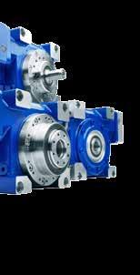

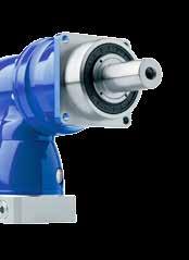

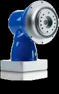
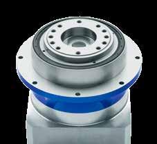
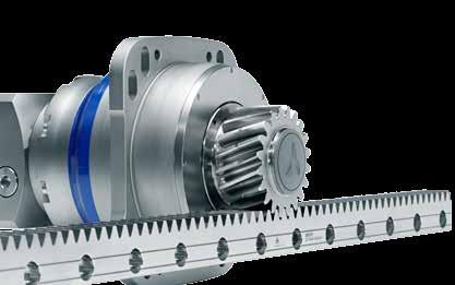

408 alpha WITTESTEI alpha GmbH Walter-Wittenstein-Straße Igersheim Germany SIT S.p.. Viale. Volta, Cusago (MI) - Italy Tel Fax Web: - info@sitspa.it Central: Tel h-Service-Hotline: Tel speedline : Tel oder info-alpha@wittenstein.de Technical changes reserved WITTESTEIalpha_Components_&_Systems_Catalog_en_2013_I WITTESTEI alpha intelligent drive systems
alpha Components & Systems Low backlash planetary gearheads Servo right-angle gearheads Mechanical systems
 alpha Components & Systems Low backlash planetary gearheads Servo right-angle gearheads Mechanical systems Competence in many sectors alpha Machine tools and manufacturing systems Maximum precision, process
Gear Boxes and Rack & Pinion
 Gear Boxes and Rack & Pinion Delivering precision in motion. As a manufacturer of the world's first precision planetary gearbox, WITTENSTEIN continues to create cutting-edge engineered technology for -
Low backlash planetary gearheads Economy
 Low backlash planetary gearheads Economy LP + Innovation sets standards The low-backlash LP + planetary gearhead extends and completes the product portfolio. Up to 75% higher torques oise level halved
V-Drive Technical brochure. Maximum power density Constant torsional backlash Supreme smooth running
 V-Drive Technical brochure Maximum power density Constant torsional backlash Supreme smooth running V-Drive Basic The quiet endurance runner Servo worm gearheads with output shaft and hollow shaft. The
alpha Value Line Individual Talents Efficient Flexible Reliable
 alpha Value Line Individual Talents Efficient Flexible Reliable WITTENSTEIN alpha adapted for any axis The perfect drive solution for every requirement WITTENSTEIN alpha develops complete, single-supplier
Low backlash planetary gearheads General
 Low backlash planetary gearheads General alpha Value Line Individual talents - Low-backlash planetary gearheads with output shaft (P, PL, PS, PR) or output flange (PT) - pplications in cyclic or continuous
HG + New hollow shaft precision
 ew hollow shaft precision The successor to our versatile hypoid gearhead with hollow shaft on one/both sides. With the, low torsional backlash and high torsional rigidity assure maximum positioning accuracy
Low backlash planetary gearheads Economy
 Low backlash planetary gearheads Economy LP + Economical multitalent Low backlash planetary gearhead with output shaft pplications in cyclic or continuous operation Torsional backlash 8 arcmin Ratio: 3-100
alphira Economical entry-level model
 Economical entry-level model The low backlash planetary gearhead with output shaft. This economical entry level model is suitable for simple applications. The impresses through its quality, availability,
HG + HG + New hollow shaft precision. The successor to our versatile hypoid gearhead with hollow shaft on one/both sides Version HG +
 ew hollow shaft precision The successor to our versatile hypoid gearhead with hollow shaft on one/both sides Version Specifications + ++ +++ Positioning accuracy Rigidity Smooth-running Speed capacity
Products 2011/12. Low backlash planetary gearheads. Servo right-angle gearheads. Mechanical systems
 Products 2011/12 Low backlash planetary gearheads Servo right-angle gearheads Mechanical systems Introduction to the WITTESTEI / alpha Catalog for 2011 / 2012 Welcome to your latest edition of the WITTESTEI/alpha
SK + / SPK + The NEW Precision Low-Backlash Right-Angle Gearhead I
 SK + / SPK + The NEW Precision Low-Backlash Right-Angle Gearhead 2006 - I 2 SK + /SPK + unlimited freedom The new SK + and SPK + right-angled gearhead series from alpha boasts a number of unique characteristics
alpha Advanced Line Product Flyer Powerful Compact Precise
 alpha Advanced Line Product Flyer Powerful Compact Precise Our drive: To become even better. The gearboxes in the alpha Advanced Line are further proof of WITTENSTEIN alpha s ongoing commitment: to make
alpha Value Line - NPR Sizing and Technical Data Efficient Flexible Reliable
 alpha Value Line - PR Sizing and Technical Data Efficient Flexible Reliable alpha Value Line P PS PL PT Ratios PR 3-100 Torsional backlash [arcmin] 8 Output type Smooth output shaft Grooved output shaft
alpha Value Line - NP Sizing and Technical Data Effi cient Flexible Reliable
 alpha Value Line - P Sizing and Technical Data Effi cient lexible Reliable alpha Value Line P PS PL PT PR Ratios 3-100 Torsional backlash [arcmin] 8 Output type Smooth output shaft Grooved output shaft
alpha Basic Line WORM GEARBOXES CVH / CVS
 alpha WORM GEARBOXES CVH / CVS If the focus is on smooth running, smooth synchronization properties, and continuous operation, the V-Drive Basic is the right choice for you. 86 CVH Worm Gearboxes CVS 87
alpha Value Line - NPS Sizing and Technical Data Efficient Flexible Reliable
 alpha Value Line - NPS Sizing and Technical Data Efficient Flexible Reliable alpha Value Line NP NPS NPL NPT NPR Ratios 3-100 Torsional backlash [arcmin] 8 Output type Smooth output shaft Grooved output
LP + Generation 3 Innovation sets standards
 alpha LP + Generation 3 Innovation sets standards intelligent solutions compact design reliable partner LP + Generation 3 Innovation sets standards LP + Generation 3 pushes back the limits! By revising
alpha Value Line - NPT Sizing and Technical Data Efficient Flexible Reliable
 alpha Value Line - PT Sizing and Technical Data Efficient lexible Reliable alpha Value Line P PS PL Ratios PT PR 3-100 Torsional backlash [arcmin] 8 Output type Smooth output shaft Grooved output shaft
LP + / LPB + Value Line economic and multi-talented II
 LP + / LPB + Value Line economic and multitalented 2005 II a WITTENSTEIN AG company 32 LP + /LPB + Value Line A winning team and right on course The finest clippervessel is nothing without an expert crew
Accessories smart additions for efficiency and intelligent performance
 smart additions for efficiency and intelligent performance Metal bellows couplings Perfectionists you can count on Metal bellows couplings are designed for the highest requirements in servo drive technology.
alpha Rack & Pinion System a perfect combination of gearhead, pinion and rack ranging from low-cost to high-end systems
 294 alpha Rack & Pinion System a perfect combination of gearhead, pinion and rack ranging from low-cost to high-end systems alpha Rack & Pinion Systems Details www.rack-pinion.com 295 alpha Rack & Pinion
premo servo actuators
 servo actuators 20 21 the powerful servo actuator platform Absolute precision meets perfect motion: combines precision with motion more efficiently than ever. The central idea behind the first fully scalable
Precision Drives Precision Gears Performance in Accuracy
 Precision Gears Performance in Accuracy Your addition in transmission. The foundations were laid over 100 years ago: In the small mill belonging to the Stephan family in the 1890s, everything already
Dynamic Precise Individual. alpha Linear Systems Product catalog
 Dynamic Precise Individual alpha Linear Systems Product catalog alpha alpha Linear Systems Product catalog Dynamic Precise Individual 3 2018 by WITTENSTEIN alpha GmbH All technical specifications were
H Synchronous Precision. T Compact Precision. S Classic Precision. Low-Backlash Servo Gearhead. V-Drive C 01/04 US Technical modifications reserved.
 H Synchronous Precision T Compact Precision Low-Backlash Servo Gearhead V-Drive C 01/04 US Technical modifications reserved. S Classic Precision 7 8 10 The Best of TOP100 Germany prize is among the highest-profile
Linear Systems Solutions Defining the Future with the Schaeffler Group
 Linear Systems Solutions Defining the Future with the Schaeffler Group LINEAR ACTUATORS Linear Solutions Provider Part retrieval systems, palletizers, custom tool changers, and dispensing robots are a
Corrosion Resistant / Hygienic Design. Hygienic Reliable Resistant
 Corrosion Resistant / Hygienic Design Hygienic Reliable Resistant Reliable driving in a hygienically clean environment Corrosion protection is vitally important for quality and maintenance optimized production
HG+ Precise hollow shaft solution
 Precise hollow shaft solution The versatile hypoid gearboxes of the alpha Advanced Line are available with a hollow shaft on one or both sides. With the, the low torsional backlash and high torsional rigidity
alpha Rack & Pinion System
 alpha Rack & Pinion System Precise Dynamic Efficient alpha Rack & Pinion System New systems specially designed for your machine concepts New unique pinion connection New classes of rack Design improved
High speeds and high torque ratings combines precision with high economic efficiency
 Drive Technology \ Drive Automation \ System Integration \ Service 1 High speeds and high torque ratings combines precision with high economic efficiency Low backlash PSF and PSC planetary servo gear units
Precision in Accuracy
 Your addition in transmission. Precision in Accuracy MELIOR MOTION PRECISION GEARBOX PSH-D SPECIAL PRECISION GEARBOXES The Premium Group Premium Stephan Hameln, Germany Design, development and production
Just as precise as your motion control application siemens.com/servo-geared-motors
 SIMOTICS S servo geared motors Just as precise as your motion control application siemens.com/servo-geared-motors All components operate together in a coordinated fashion: SIMOTICS S servo geared motors
Wittenstein Mechanical Systems
 Wittenstein Mechanical Systems Putting you one step ahead of the rest: Mechanical systems by WITTENSTEIN alpha More precise, more individual, more compact mechanical systems by WITTENSTEIN alpha and numerous
DKR Intelligent Digital AC Vector Drives 35 to 330 hp (26 to 245 kw)
") Industrial Hydraulics Electric Drives and Controls Linear Motion and Assembly Technologies Pneumatics Service Automation DKR Intelligent Digital AC Vector Drives 35 to 330 hp (26 to 245 kw) The Drive &
Industrial Hydraulics Electric Drives and Controls Linear Motion and Assembly Technologies Pneumatics Service Automation DKR Intelligent Digital AC Vector Drives 35 to 330 hp (26 to 245 kw) The Drive &
Products and Solutions
 cyber motor Products and Solutions Servo motors Drive electronics Drive systems WITTENSTEIN cyber motor GmbH Comprehensive product expertise - Rotary and linear servo motors and servo actuators - Drive
SIMOTICS S-1FK7 Servomotors
 Siemens G 1 Compact Synchronous Motors for Motion Control pplications Motors Brochure Edition October 1 nswers for industry. Siemens G 1 SIMOTICS Motors for Motion Control Tasks The right motor for every
Webasto Service 360. The best approach to an optimal solution is all-round.
 Webasto Service 360 The best approach to an optimal solution is all-round. A new approach to Service. Webasto is present with over 50 locations around the world. Our roof and convertible roof as well as
Siemens AG SIMOTICS T-1FW3 Torque Motors. The Powerful Torque Motors. Edition February Brochure. siemens.
 SIMOTICS T-1FW3 Torque Motors The Powerful Torque Motors Brochure Edition February 2017 siemens.com/torquemotors The powerful torque motors Overview The right torque at the right moment this is decisive
TQ-TQK-TR-MP LC-LCK-SL-KR Series. Precision Planetary Gearboxes
 TQ-TQK-TR-MP LC-LCK--KR Series Precision Planetary Gearboxes OUR PRODUCTS AT A GLANCE PRODUCT INLINE RIGHT ANGLE PRODUCT LINE-UP CONFIGURATIONS HIGH PERFORMANCE NEW TQ NEW TQK Yes Yes Highest Precision
Demag KB conical-rotor brake motors. Drives with unique principle
 Demag KB conical-rotor brake motors Drives with unique principle 37468 Demag KB conical rotor brake motors: Demag KB conical rotor brake motors offered by Demag Cranes & Components feature a unique principle:
 --554-6 www.microngearheads.com Mechanical and Electro-Mechanical Product Solutions by Danaher Motion Danaher Motion engineers, manufactures and markets a select combination of the world s top brands of
SIMOTICS FD looks different, offers more
 SIMOTICS FD looks different, offers more The new definition of the asynchronous motor siemens.com/simotics-fd siemens.com Power, flexibility and efficiency redefined A motor is not always a motor. The
cyber dynamic line brushless servo motors
 cyber motor cyber dynamic line brushless servo motors dynamic high-torque efficient Your Applications WITTENSTEIN Products that know no limits Adhesive Dispensing Brushless servo motors with the highest
Servo-pneumatic drive solution for welding guns. Top quality welding!
 Servo-pneumatic drive solution for welding guns Sturdy and precise! Top quality welding! Highlights Extremely short cycle times High quality and outstanding reproducibility of the spot welds Excellent
Tandler. ServoFoxx Servo Gearheads
 Tandler ServoFoxx Servo Gearheads ServoFoxx Inline and Right Angle Planetary Servo Gearheads The Tandler ServoFoxx series of servo gearheads provide the ultimate in precision motion control for highly
EMC-HD. C 01_2 Subheadline_15pt/7.2mm
 C Electromechanical 01_1 Headline_36pt/14.4mm Cylinder EMC-HD C 01_2 Subheadline_15pt/7.2mm 2 Elektromechanischer Zylinder EMC-HD Short product name Example: EMC 085 HD 1 System = ElectroMechanical Cylinder
Frameless Torque Motor Series
 Frameless Torque Motor Series QUALITY AND SERVICE DELIVERED WORLDWIDE [ TECNOTION ] Tecnotion is the global authority on direct drive motor technology. We are the world s only unbundled manufacturer of
SIMOTICS S-1FT7 Servomotors. The Compact Servomotors for High-Performance Motion Control Applications. Motors. Edition April 2017.
 Motors SIMOTICS S-1FT7 Servomotors The Compact Servomotors for High-Performance Motion Control Applications Brochure Edition April 2017 siemens.com/servomotors The Servomotors for High-Performance Applications
Power Jacks have taken time, engineering excellence and the best people to produce the ultra compact Neeter Drive gearbox.
 202 www.powerjacks.com Power Jacks have taken time, engineering excellence and the best people to produce the ultra compact Neeter Drive gearbox. Our expertise has been built on a history of engineering
Precision gearbox brochure
 Precision gearbox brochure Economy Line For any mounting position Individual adaptation of the input flange to the motor Lifetime lubrication for maintenance-free operation Clamping systems with optimized
We want a competitive edge for our packaging machines. Here come the automation solutions of AMK.
 We want a competitive edge for our packaging machines. Here come the automation solutions of AMK. We are looking for a partner With a lot of experience and fresh ideas. amk is making a difference in machine
Contents. Page. 1. Product description. 2. The AXC line of linear axes. 3. AXLT line of linear tables. AXC and AXS product overview...
 SNR Industry Contents Page 3 1. Product description AXC and AXS product overview... 6-8 Dynamic load ratings of the linear motion systems... 9 Compact modules... 10-11 Linear tables... 12 Telescopic axes...
Highest Performance: SPH Series
 Highest Performance: Series The series features helical gearing which brings a whole new level of power and precision to GAM s already extensive portfolio of gear reducer technology. With special attention
DRIVE SOLUTIONS FOR THE TYRE INDUSTRY DRIVESYSTEMS
 INTELLIGENT DRIVESYSTEMS, WORLDWIDE SERVICES EN DRIVE SOLUTIONS FOR THE TYRE INDUSTRY DRIVESYSTEMS NORD DRIVESYSTEMS Intelligent Drivesystems, Worldwide Services NORD DRIVE SOLUTIONS FOR THE TYRE INDUSTRY
NEXEN WHITEPAPER. Nexen Group, Inc. 560 Oak Grove Parkway / Vadnais Heights, MN /
 NEXEN WHITEPAPER Roller Versatility, Pinion Precision Systemand Short Lead Times: The CRD MR Rotary Indexer Nexen s new indexer is a cost-effective solution for automating a wide variety of tasks. Whether
Permanent magnet brakes. Safety from the market leader. PM Line High Torque Line
 Permanent magnet brakes Safety from the market leader PM Line High Torque Line Industrial Drive Systems Die Welt von Kendrion Industrial Drive Systems Kendrion The brake experts As a solution provider,
Variety and creativity
 Variety and creativity 2 THE GEAR COMPANY Where to find what Graessner Yesterday and Today Page 4 Labyrinth- and Switch-/ Reverse Gear Boxes Thank you for your interest in our products. Our current staff
NEW. Linear Ball Bushing Bearings and 60 Case Shafting. Profile Rail Linear Guides
 Linear Ball Bushing Bearings and 60 Case Shafting Thomson invented the ball bushing bearing over 60 years ago and has since been the recognized leader in this field. Our linear products provide low friction,
Gear Drive Solutions a Dedicated and Reliable Partner
 Gear Drive Solutions a Dedicated and Reliable Partner /// Gears, spindle gears, actuators, motors etc. /// Flange bearing and pillow block bearing units /// Standard or customized products /// Complete
Your idea - Our drive. Custom engineered drive solutions for the medical & rehabilitation device industry.
 Your idea - Our drive. Custom engineered drive solutions for the medical & rehabilitation device industry. Franz Morat Group: Your experienced partner for rehabilitation and medical technology solutions
TRUE Planetary Gearheads
 TRUE Planetary Gearheads Danaher Motion - Helping you build a better machine, faster Danaher Corporation combined over 3 industry-leading brands such as Kollmorgen, Thomson, Dover, Pacific Scientific,
Tandler. Hypoid. Servo Gearheads
 Tandler Hypoid Servo Gearheads ServoFoxx Hypoid Gearboxes The new Hypoid gearbox from Tandler offers the ultimate in performance and connection versatility for dynamic servo driven applications. Benefits:
Active launch systems. For passenger cars up to 1,000 Nm
 Active launch systems For passenger cars up to 1,000 Nm 2 3 Powertrain components and systems for passenger cars and LCV Performance comfort environmental protection. Powertrain components and systems
Milling spindles / H line Up to speed fast: Dynamic and robust for high loads
 Milling spindles / H line Up to speed fast: Dynamic and robust for high loads SPINDLE TECHNOLOGY I SYSTEM TECHNOLOGY I DRIVE TECHNOLOGY I SERVICE SOLUTIONS www.kessler-group.biz Specialist partner KESSLER
TRUE Planetary Gearheads
 TRUE Planetary Gearheads Danaher Motion - Helping you build a better machine, faster Danaher Corporation combined over 3 industry-leading brands such as Kollmorgen, Thomson, Dover, Pacific Scientific,
Intelligent solutions for reliable wind turbines.
 Intelligent solutions for reliable wind turbines. EMPOWERING FORCES. EMPOWERING FORCES. Wind power is one of the most important sources of energy for the world of tomorrow. High-quality components, an
POWERGEAR. Miniature NEW. Actual Size. Impressively small and incredibly powerful.
 MS-Graessner GmbH & Co. KG THE GEAR COMPANY POWERGEAR Miniature NEW Impressively small and incredibly powerful. Actual Size The bevel gearbox with minimum size at maximum performance and precision The
Locking Assemblies & Locking Elements
 US 01 2016 Locking Assemblies & Locking Elements Partner for Performance www.ringfeder.com Welcome to your system supplier for every aspect of power transmission Today s RINGFEDER POWER TRANSMISSION GMBH
GPL Series Robotic Planetary Gearboxes
 GPL Series Robotic Planetary Gearboxes Robotic Planetary Gearboxes GM s GPL Series Robotic Planetary Gearboxes provide the lowest backlash and high tilting rigidity for horizontal and vertical robotic
Friction Management Solutions for Industrial Gear Drives
 Friction Management Solutions for Industrial Gear Drives A complete range of bearings and complementary services help the gear drive industry to meet ever-increasing requirements in product reliability
A member of the UNITED GRINDING Group. The Art of Grinding. PRODUCT RANGE. The Art of Grinding.
 The Art of Grinding. A member of the UNITED GRINDING Group The Art of Grinding. GLOBAL PERFECTION CUSTOMER FOCUS PRECISION TECHNOLOGY LEADER GLOBAL EFFICIENCY SAFETY SOPHISTICATED PROCESSES The Art of
Motion without compromise
 Toothed belt and spindle axes ELGA Clean, protected, strong Motion without compromise Highlights Protected: insensitive to harsh ambient conditions Clean: virtually no particle emissions for use in cleanrooms
Reliability is our profession
 Reliability is our profession Drive components for wind turbines Siemens AG Am Industriepark 2 46562 Voerde Germany Phone +49 2871 92-4 Fax +49 2871 92-2487 E-Mail info@winergy-group.com www.winergy-group.com
The optimum geared motor for every motion control application. Brochure April 2007
 The optimum geared motor for every motion control application Brochure April 2007 Geared servo motors overview For motion control applications, Siemens offers an extensive range of rotary servomotors.
WPLE. The right angle gearbox of the PLE series with circular output flange. Economy Line
 44 The right angle gearbox of the series with circular output flange The is the logical refinement of our series. This right angle gearbox series was designed especially for spacesaving installation in
Schaeffler Global Technology Network. Together we move the world
 Schaeffler Global Technology Network Together we move the world Working together to turn challenges into opportunities Globalization opens up limitless opportunities for companies while at the same time
Our Mission. Our Brand Promise
 M O D U L A R A C T U A T O R S P R O D U C T w w w. n o o k i n d u s t r i e s. c o m G U I D E Our Mission Our mission is to be an innovative and responsive organization. Nook Industries knowledge and
PRODUCT OVERVIEW HIGHEST PRECISION
 PRODUCT OVERVIEW If you need high precision gear reducers at a reasonable cost and you value innovation and excellent service, take a close look at our product line. You ll find a wide range of products
SCHMIDT-KUPPLUNG GmbH
 Loewe GK About us Many years of experience For 50 years, we have been advising machine manufacturers as partners for compact coupling systems. Our experience in power transmission has given us extensive
Catalog DRE Gearmotors (IE2)
") Drive Technology \ Drive Automation \ System Integration \ Services Catalog DRE Gearmotors (IE2) Edition 11/2013 20152558 / EN SEW-EURODRIVE Driving the world Contents Contents 1 Introduction... 6 1.1
Drive Technology \ Drive Automation \ System Integration \ Services Catalog DRE Gearmotors (IE2) Edition 11/2013 20152558 / EN SEW-EURODRIVE Driving the world Contents Contents 1 Introduction... 6 1.1
Formation and finishing
 System Engineering for the battery industry Formation and finishing of lithium-ion cells 2 3 Extensive experience, a global leader with close proximity to the customers thyssenkrupp System Engineering
THE FASCINATION OF POWER & ROTATION
 THE FASCINATION OF POWER & ROTATION A PERFECT FIT: YOUR NEEDS OUR SPINDLES ALWAYS ONE TURN AHEAD At IMT, everything revolves around the spindle and all the associated solutions. A proper understanding
L1 (Standard Motor Length) L2 (Brake Motor Length)
 L2 (Brake Motor Length)") HepcoMotion Geared Motor Option The optional geared motor will be the preferred choice for many applications as it provides an excellent combination of power, accuracy, flexibility and value. HepcoMotion
HepcoMotion Geared Motor Option The optional geared motor will be the preferred choice for many applications as it provides an excellent combination of power, accuracy, flexibility and value. HepcoMotion
SYNCHRONIZATION SYSTEMS
 SYNCHRONIZATION SYSTEMS Partners for Solutions TWO PARTNERS ONE JOINT SOLUTION Dear Customer, This cooperation highly suggests itself, not only because of our close proximity to each other at several locations
Linear Motion Technology Handbook. The Drive & Control Company
 Linear Motion Technology Handbook The Drive & Control Company 1-2 Bosch Rexroth AG Linear Motion Technology Handbook R310EN 2017 (2006.07) Linear Motion and Assembly Technologies www.boschrexroth.com/brl
The new light crane system KBK Aluline The new standard for ergonomics
 The new light crane system KBK Aluline The new standard for ergonomics Connect with efficiency We invented smooth operation for easy load handling And we have now redefined it International studies prove
ZTRS/ZTR/ZR rack and pinion drives. The highly efficient rack and pinion drive with innovative pinion bearing
 ZTRS/ZTR/ZR rack and pinion drives The highly efficient rack and pinion drive with innovative pinion bearing Drive optimisation for machine tool manufacture The compact solution for more efficiency In
Chain drive components. Perfectly linked for your success.
 Chain drive components. Perfectly linked for your success. The content of this brochure is not legally binding and is solely intended for information purposes. Where legally permissible, all liability
Raising the bar on end-to-end conveyor solutions. SIMOGEAR High-efficiency Geared Motors.
 Raising the bar on end-to-end conveyor solutions SIMOGEAR High-efficiency Geared Motors www.usa.siemens.com/simogear SIMOGEAR extends the portfolio and expertise of the only automation supplier in the
Advanced Electromechanical Actuation Components to Solutions Systems
 Advanced Electromechanical Actuation Components to Solutions Systems Components to Solutions For over 25 years, Exlar has been providing advanced and robust electromechanical actuators for applications
Hydraulic Drive Technology for Woodworking Machinery
 Hydraulic Drive Technology for Woodworking Machinery 1 Drive & Control everything for keeping things moving. Whether your drive and control solutions are hydraulic, pneumatic, electric or mechanical being
Proven to be better. Development trends in industrial rolling bearings
 Proven to be better Development trends in industrial rolling bearings Contents 1. General trends in power transmission and in machine construction and plant engineering Page 3 2. General trends in rolling
Linear & Rotary Actuators F-41
 & F-41 & DRS Series Equipped Page Series Equipped F-4 F-41 F-4 Series Equipped $ $ For detailed information about regulations and standards, please see the Oriental Motor website. The Series is a line
EJP SERIES Right-angle Worm
 EJP SERIES T he EJP series is ideal for demanding applications requiring high efficiency, torsional rigidity and zero backlash. It s lightweight, black anodized aluminum housing and dual input/output seals
How do you build a great idea? The optimised standard in industrial gear unit technology. FLENDER SIG horizontal standard gear units. siemens.
 How do you build a great idea? The optimised standard in industrial gear unit technology FLENDER SIG horizontal standard gear units siemens.com/sig FLENDER SIG a great idea is made reality Industrial experience
White paper: Pneumatics or electrics important criteria when choosing technology
 White paper: Pneumatics or electrics important criteria when choosing technology The requirements for modern production plants are becoming increasingly complex. It is therefore essential that the drive
Motors and Gearboxes for Material Handling. Innovative Energy efficient Reliable
 Motors and Gearboxes for Material Handling Innovative Energy efficient Reliable Reliability In All Areas ABM Greiffenberger develops and manufactures cutting edge drive solutions in highest quality. Individual
HARMONIC GEARHEAD. Features & Benefits Specifications... 53
 HARMOIC GEARHEAD exen s revolutionary (HG) is the perfect combination of size and precision. Use the integrated with exen s RPS Pinion (HGP) to create a true backlash-free solution from the motor to the
Costumer Service. Comprehensive technical support for NETZSCH customers
 Costumer Service Comprehensive technical support for NETZSCH customers NETZSCH Pumps & Systems Your partner for high quality products and first class service With NEMO progressing cavity pumps, TORNADO