Galli&Cassina Profile
|
|
|
- Joleen Hines
- 6 years ago
- Views:
Transcription

1 Since 1919
 with extensive offices and workshop A2 MALPENSA A8 A7 GENOVA MILANO BOLOGNA BERGAMO A1 A4 covering a12.000 sq.mt. area including 5.000 sq.mt.of covered space.")

2 Galli&Cassina Profile TORINO Galli&Cassina is a prominent Italian Company mainly involved in the manufacture of a complete range of Lubricated Plug Valves. The company is located in Solaro near Milan (Italy) with extensive offices and workshop A2 MALPENSA A8 A7 GENOVA MILANO BOLOGNA BERGAMO A1 A4 covering a sq.mt. area including sq.mt.of covered space. Galli&Cassina was established in1919, and it is one of the oldest Italian companies still involved in the manufacturing of valves. At this early stage the business activity was concentrated in the production of valves for domestic and industrial purposes. BRESCIA 2 After the first ten years the company gradually directed its production towards the newly born Chemical industry; it was the first in Italy to produce valves in stainless steel and other new material cooperating with the demand of the most important chemical Companies. It was not possible to expand the Milan factory any more which was built in 1930 and enlarged after the second world war. For this reason in 1991 Galli&Cassina moved to a new factory in Solaro (Milan) with a very modern plant equipment, very comfortable for the workers. After 30 years of experience in chemical valves, Galli&Cassina started the production of Plug Valves in the Oil &Gas business becoming one of the most significant suppliers for all International Gas&Oil Companies all over the world.


 - Washington (U.S.A.). Nowadays Galli&Cassina is proud to celebrate its 90 years, presence in the world of the valve market.")
3 Its sales activity covers most of the continents with a leading and growing presence in Europe, Middle East, North & South America and Far East resulting in a sales and service network with subsidiaries, branch offices and distributors, acquiring a reputation on high quality workmanship as well as on the reliability of its products. Special care is due to the development in every aspect of the Company s management, complying with the continuous changes, requested by the evolution of the International markets. The proved technical, productive, and financial capabilities combined with the experience of human resources are the result of Galli&Cassina reputation all over 3 the world. Galli&Cassina s Quality Assurance System ISO has been assessed, approved and certified by Lloyd s Register, while the API 6D and 6A monogram have been certified by API (American Petroleum Institute) - Washington (U.S.A.). Nowadays Galli&Cassina is proud to celebrate its 90 years, presence in the world of the valve market. Galli&Cassina s historical background and experience allow the Company to offer strong professionalism and a comprehensive range service. That will surely guarantee results in the future.

4 4
5 Index Company Profile 2-3 Maching & Manufacturing Facilities 4 Index 5 Galli&Cassina Products Material Selection Guide for 6 GALLI&CASSINA Valves Standard Design Categories (Typical Construction Materials) Applicable Standard-Specification 7 Standard Features 8 The Pressure Balance System Standard Features Patterns Standard Features Plug PTFE Antifriction Treatment 9 Special Features Coating & Overlay 10 Fire Safe Test Available Tests 11 Advanced Design Valve Assembly 14 Valve with Wrench Cross Section Drawing 15 Product Identification System 16 ANSI Class 150 to (PN 20 to PN 420) ANSI Class 150 (PN 20) ANSI Class 300 (PN 50) ANSI Class 600 (PN 50) ANSI Class 900 (PN 150) 26 ANSI Class 1500 (PN 250) 27 ANSI Class 2500 (PN 420) 28 Engineering Data Pressure Balanced Plug Valves 29 API 6A Hydraulic Pressure Test Duration 30 Marking PressureTestTables in 31 Accordance with API 598 & API 6D Quality Assurance Programme 32 Quality Assurance System 33 Quality Assurance Development Customer Service Quality Assurance Programme Lubricants 34 Hydraulic Grease Gun N Lubricants List 35 Routine Maintenance Instructions 36 Engineering Data 37 Conversion Tables Temperature Conversion Table 40 Pressure/Temperature Rating 41 according to ASME B Chemical and Mechanical Requirements Forged/ bar Materials for Body, Plug, Cover and Stem Components Chemical and Mechanical Requirements Cast Materials for Body, Plug and Cover Components Chemical and Mechanical Requirements Bolting Materials (Body/Plug) Plug Valve Dimensions according to API Standard 6D/ ISO Plug Valve Dimensions according 48 to API Standard 6A/ ISO Qualification of other Size 49 Valves - API 6FA Qualification of other Pressure Rating Valves Plug Valve Application 50 The Production Range 51 Actuators Availability GALLI&CASSINA in the World 53 The data reported in this catalogue refer to the International Standards applicable at the time of its issue date. Galli&Cassina reserves the right to modify its products without any obligation to notify, provide or install such modification on products previously or subsequently sold. However Galli&Cassina will use the best afford to keep the customers informed of any changes made. GALLI&CASSINA 5
6 Material Selection Guide for GALLI&CASSINA Valves Trim materials are designed according to the service conditions. 1 Standard Carbon Steel Body and Plug. (ASTM-A216 WCB/WCC material) suitable for general services. 2 Carbon Steel Body and Plug (A352 LCB/LCC material) suitable for low temperature services. 3 Carbon Steel Body and Plug (ASTM A216WCB/WCC material) suitable for SOUR SERVICE (H 2 S and CO 2 ) according to NACE-MR.01.75/Latest Edition. 4 Special Austenitic (6MO) and Ferritic-Austenitic Stainless Steel (Duplex and Superduplex) suitable for sea water and corrosive services. 5 Nickel-Chromium-Iron alloy (i.e. Alloy 20), Titanium & Titanium alloy, carbon steel with Inconel 625 cladding and stellite or Tungsten carbide hardfacing for abrasive/corrosive service. 6 Other materials upon request. Standard Design Categories (Typical Construction Materials) Stem and Trim Service Class Body/Cover Plug Oldham Coupler Bolting 1 Standard service ASTM A105 ASTM A105 ASTM A29 Gr ASTM A193-B7M Natural gas 150 to 2500 ASTM A216 ASTM A216 ASTM A194-2HM Hydrocarbons WCB/WCC WCB/WCC Max C 0.25% 2 Low temperature ASTM A350-LF2 ASTM A350-LF2 ASTM A29 Gr ASTM A320-L7 Natural gas 150 to 2500 ASTM A352 ASTM A352- ASTM A194 Gr.7 Hydrocarbons LCB/LCC LCB/LCC Max C 0.23% 3 Sour Service ASTM A105 ASTM A105 ASTM A29 Gr ASTM A193-B7M (H 2 S and CO 2 ) 150 to 2500 ASTM A216 ASTM A216 Max HRC22 ASTM A194-2HM Hydrocarbons WCB/WCC WCB/WCC MAX HRC22 Max C.0.23% Max C.0.23% Max HRC22 Max HRC22 4 Sea Water 150 to 2500 UNS S31254 ASTM A 351 UNS S31254 UNS S31254 ASTM A453 Gr.660A CK3MCuN (6MO) UNS S31803 UNS S31803 UNS S31803 ASTM A453 Gr.660A ASTM A 890 UNS S32760 J92205 (Duplex 22% Cr) UNS S32750 UNS S32750 UNS S32750 UNS S32760 ASTM A 890 J93404 (Super duplex 25% Cr) UNS S32760 UNS S32760 UNS S32760 UNS S32760 ASTM A 890 J93380 (Super duplex 25% Cr) 5 Abrasive/Corrosive 150 to 2500 Slurry service ASTM B348 Gr 3 or 5 ASTM B348 (Titanium) GR 3 or 5 UNS S31254 UNS S32760 ASTM A453 Gr.660A UNS N08020 UNS N08020 UNS S32750 ASTM A453 Gr.660A ASTM A351CN7M ASTMA351CN7M UNS S32760 UNS S32760 (Alloy 20) ASTM A 105 ASTM A 29 ASTM A193 B7M ASTM A 216 WCB/WCC Gr 4140 ASTM A194 2HM Hardfacing(Stellite/WC) and Cladding (Inconel 625) 6

7 Applicable Standard-Specification Lubricated Plug Valves are designed to use with most refining services according to API 599 or BS 5353 norms whichever is applicable. API 6D norm aims to standardize the materials as well as instructions to manufacture valves suitable for energy transportation in the pipelines. API 6A API 6D API 6FA API RP6F API 598 API 599 ASME/ANSI B 16.5 ASME/ANSI B ASME/ANSI B ASME/ANSI B ASME/ANSI B 31.3 ASME/ANSI B 31.4 ASME/ANSI B 31.8 ASME ASME ASNT-TC-1A Specification for wellhead and christmas tree equipment. Specification for Pipeline Valves. Specification for Fire Test for Valves. Recommended - Practice for Fire Test for Valves. Valve Inspection and Testing. Steel Plug Valves Flanged or Butt Welding Ends. Pipe Flanges and Flanged Fittings. Face-to-Face and End-to- End Dimensions of Valves. Buttwelding Ends. Valves-Flanged, threated and Welding Ends. Chemical Plant and Petroleum Refinery Piping. Liquid Trasportation System for Liquid Petroleum Gas. Gas Transmission and Distribution Piping System. Boiler and Pressure Vessel SECTION VIII - DIV.1 & 2 Boiler and Pressure Vessel Section V. Reccommended Practice for Personnel Qualification and Certification in Non destructive Testing. BS 1504 BS 2080 BS 5353 BS 6755 part 1 BS 6755 part 2 CSA Z MSS-SP6 MSS-SP25 MSS-SP44 MSS-SP53 MSS-SP54 MSS-SP55 MSS-SP61 NACE Std. MR Latest Edition ASTM Specification for Steel Casting for Pressure Purposes. Face to Face - Centre to Face - End to End - Steell Valves. Specification for Steel Plug Valves. Testing of Valves (Spec. for Production Pressure Testing Requirements). Testing of valves (Spec. for Fire Safe Testing Requirements). Canadian Standard Association. Standard Finish for contact Face of Pipe Flanges. Standard Marking System for Valves. Steel Pipe Line Flanges. Quality Standard for Steel Casting-Magnetic Particle Examination Method. Quality Standard for Steel Casting-Radiographic Examination Method. Quality Standard for Steel Casting Visual Method. Pressure Testing of Steel Valves. National Association of Corrosion Engineers. American Society for Testing and Materials. 7


8 Introduction Plug Valves are probably the oldest and most commonly used valves in modern pipelines. Plug Valves have been used more than 2000 years, ever since the time of ancient Rome. Standard Features: the Pressure Balance System The operating system of Pressure Balanced Plug Valves (shown in Fig.A) consist in the pressure equalization between the port area and the top/bottom of the plug with two holes. The upper hole connects the plug port area with the top of the plug, while the lower maintains the pressure equalization between the port area and the bottom of the plug. The Pressure Balance System ensure line pressure acts on the plug to reduce the valve torque and avoid the possibility of plug seizure, even after a prolonged time in the open or closed position. The tapered shape of the plug guarantees that the force created by line pressure pushes the plug against the body seat. As differential pressure increase so does the sealing capability of the Pressure Balanced Standard Features Patterns: Galli &Cassina Plug Valves are available in four different patterns. The pattern indicates basic information about the Short Pattern Short Pattern Plug Valves have compact face to face dimensions (like a Gate Valve) and port areas of 40% to 60% of a Full Bore Plug Valve. This provides an economical valve for services where some reduction of flow rates can be tolerated. The Short Pattern is only in classes 150 and 300. Lubricated Plug Valves use special lubricant to easy their operation over a wide range of operating pressure. The lubrication film (between plug and body) also provides a Regular Pattern Regular Pattern Plug Valves have longer face to face dimensions and port area of 50-70%. This configuration provides minimal loss of flow while economising on the overall valve dimensions from using rectangular port. 8 seal and only requires periodic lubricant injection. No spare parts. Bubble tightness is always guaranteed in critical service. Maintenance is reduced UPPER HOLE LOWER HOLE Figure A valve in terms of end to end dimension (according to API 6D & BS 5353) & the size of the flow port through the valve. Venturi Pattern Venturi Pattern Plug Valves also have a longer face to face but with a small port opening of 40-50%. These are typically used on services where flow rate is not critical. The long lead into and out of the port minimises pressure drop when the valve is fully opened. to a periodic lubricant injection. Complete overhauling of the valve, or line shut off "are not required" in case of seat leakage. Plug Valve. Thanks to pressure balance feature, and to the integral metal to metal design, Plug Valve can always be opened against the maximum deltapi. No by-pass is necessary to preserve seat integrity. Periodic lubricant injection, and seat adjustment can be carried out when the Plug Valve is under full pressure. Only severe seat damage will cause a reduction of valve sealing. Full Bore Full Bore Plug Valves have long face to face dimensions and a round port that is not smaller than minimum diameter specified in Annex A of ASME B16.34 or/and API 6D. This configuration provides unrestricted flow and allows the passage of pigs through the valve. It is also recomanted for highly abrasive conditions as it minimises pressure drop and erosion in the valve.


9 Standard Features: Plug PTFE Antifriction Treatment Carbon Steel plugs are subjected to the following treatments: A) Case hardening. B) Antifriction treatment. The case hardening has the purpose to increase only the hardness of the plug surface which is subjected to wearing, keeping at the same time the mechanical properties of the base material unchanged. Consequently the base material has more toughness and resistance against impacts. The Antifriction treatment is basically carried out on the plug to obtain the following advantages: - Low friction between plug and body. - Low torque. - Wear resistance. - Resistance to seizure. Plug with PTFE Antifriction treatment. Plug without PTFE Antifriction treatment. Plug with PTFE Antifriction treatment. Plug without PTFE Antifriction treatment. The purpose of the above test is to prove that Galli&Cassina antifriction treatment made on plug surface, is guaranteed even after 30,000 cycles (open/closed position). 9


10 Special Features: Coating & Overlay Hardfacing The most common damages of valves are either due to abrasion by solids in the flow lines, or the exposure of main components to corrosion attack.galli&cassina s researching and development in cooperation with specialized companies and laboratories, have been the development of special hardfacing and corrosion resistant materials, which have achieved excellent results in Off-Shore application. Most of the main materials used are as follows: Stellite-Duplex-6MO Inconel 625-Nickel Alloy 686 Ultimet Alloy (UNSR31233) Tungsten Carbide. Electroless Nickel Plating The transport of wet hydrocarbon gases contaminated with hydrogen sulphide, carbon dioxide or other similar fluids containing appreciable level of sulphur, can create various corrosion problems to some component in plug valves. These environments are not always recognized under service conditions, therefore in order to obtain a high quality corrosion resistant, all the material for each component of the valves, are selected in accordance with the requirements of NACE-Std. MR Latest Edition. Moreover the use of an electroless nickel plating on plug surface provides more corrosion protection to hydrogen sulphide crack-resistant base metal. Standard ENP is in accordance with ASTM B733 Std with a minimun (76 Microns) thickness, unless otherwise specified in the customer s specification. Tungsten Carbide Coating A series of metal carbide coatings (WC+Ni, Cr or WC+Co or WC+Co, Cr), usually known as Tungsten Carbide (TCC) allows to achieve higher performance in terms of valve working life. These performances are specially highlighted in case of severe operating conditions. Moreover, higher hardness values (greater than 1100 HV / 70 HRC) compared to standard hardfacing (Stellite 6, HRC) provide a very good abrasion & wear resistance. 10


 and assembled valves HARDNESS NACE - MR.01.")
11 Fire Safe Test All Galli&Cassina s Plug Valves have been tested against fire resistence, according to API - 6FA and BS Part 2 standards and witnessed by international third party. Metal to Metal Seat, diaphragm sealing as well as the stem sealing compound with graphite guarantees a high reliability performance of our Plug Valves while in exposure to Fire Test conditions. Available Tests Type of Test Applicable Standards Performance X AND GAMMA RAYS ANSI B Annex-B 100% all butt welding ends ASME VIII - Div.1 - MSS - SP 54 and body. ASTM E446 - E186 - E280 DYE PENETRANT ASME V - art.6 and 24 - ASTM E % All butt welding ends ANSI B Annex-D MSS-SP-93 MAGNETIC - PARTICLES ASME V - art.7 and % of all valves (Dry and wet) ANSI B Annex C - MSS - SP 53 ULTRASONIC ASME V - art.4 and 23 Upon customer request ASME VIII - Div.1 - ASTM - A388 VISUAL AND DIMENSIONAL MSS - SP % of rough and finished ANSI B B16.10 machined components API 6D - (Table 4.2) and assembled valves HARDNESS NACE - MR Latest Edition 100% of wetted components HYDROSTATIC AND API - 6D - API % of all valves PNEUMATIC BS Part.1 - MSS - SP 61 OPERATION TORQUE API - 6D Upon customer request HIGH PRESSURE CLOSURE API Par. 4-5 Upon customer request POSITIVE MATERIAL ASTM A % of pressure containing IDENTIFICATION components 11


 Final")
12 Advanced Design Three -dimensional CAD system and the Finite Element Modelling allow the optimization of every step of valve s design: FEM stress calculation of the pressure containing parts (A) Raw Casting design (B) Final Assembly Design Check (C) A B C

13
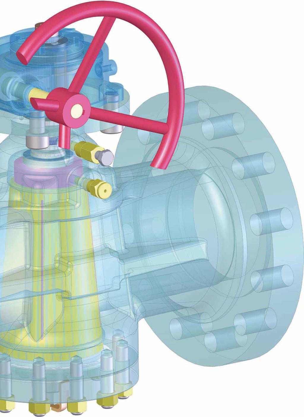
14 Valve Assembly WRENCH INDICATOR WEATHERSEAL RING GASKET RING GRAPHITE FIRESEAL BODY CAP SCREW GLAND PLATE STEM SEALING INJECTOR LUBRICANT INJECTOR CHECK VALVE UPPER THRUST WASHER STEM STEM O-RINGS EQUALISER RING PLUG BALL BEARING-RETAINER LOWER - THRUST WASHER COVER METAL DIAPHRAGM PLUG LOADING SCREW BOLT NUT LOADING SCREW CAP 14
15 Valve with Wrench: Cross Section Drawing WEATHERSEAL BLOWOUT PROOF STEM GRAPHITE PACKING FIRESEAL LUBRICATION CHAMBER STEM SEALING INJECTOR PLUG SEALANT INJECTOR PRESSURE BALANCED HOLE-WITH CHECK VALVE LUBRICANT GROOVE PLUG PLUG LOADING SCREW PRESSURE BALANCE HOLE NOTES: Each valve with wrench operation, the plug open and closed position are assured by corresponding stop indicator fitted on bare stem. The open position of the valve has the stop indicator parallel to flow direction of the fluid. 15

16 Valve with Gear: Cross Section Drawing GRAPHITE PACKING FIRE SEAL LUBRICATION CHAMBER BLOWOUT PROOF STEM GEAR BOX STEM SEALING INJECTOR PLUG SEALANT INJECTOR PRESSURE BALANCED HOLE WITH CHECK VALVE LUBRICANT GROOVE PLUG PRESSURE BALANCED HOLE PLUG LOADING SCREW NOTES: Each valve with gear operation, the plug open and closed position are assured by corresponding stop indicator fitted on top of gear. The open position of the valve has the stop indicator parallel to flow direction of the fluid. 16


17 Valve with Stem Extension: Cross Section Drawing PLUG SEALANT INJECTOR GEAR BOX STEM EXTENSION LUBRICANTION PIPE GRAPHITE PACKING FIRESEAL STEM SEALING INJECTOR PRESSURE BALANCED HOLE-WITH CHECK VALVE LUBRICATION CHAMBER PLUG LUBRICANT GROOVE PLUG LOADING SCREW PRESSURE BALANCE HOLE NOTE: Specify the distance required from the valve center - line to the handwheel center - line at the ordering time. 17
18 Product Identification System Identification numbers here shown are used to describe essential features of Galli&Cassina valves. Example: 300 B R R 06 W P B Size Valve Type 1 / / / B Pressure Balanced S* Standard V* Standard with Jacket Z* Standard Full Jacketed R Pattern V Venturi C Short R1 or W 2 Regular 3 F ** Full Bore 4 K***Short Full Bore 1 Valve size 4 2 Valve size 6 3 F-F per ASME B F-F per API 6D-(as ball valves) R 06 W P 0001 Valve Operator Type Working Pressure Class Valve End Connection Optional Special Features Internal Material Identification C Lever R Gear E Gear with Electric Motor API 6D Valves F T Threaded Socket R RF Flange W Butt Weld T Completely Buried P Partially Buried N Pups According to client s materials requirement A Actuator (Pneumatic or Gas overoil) B Bare Stem API 6A Valves K B Butt Weld by Flange J Ring Joint Flange C Clamp J Partially Buried and Pups The Code used as sample above ( 300 B R R 06 W P 0001) identifies a: DN 300 (12 ) - Pressure balanced plug valve - Regular pattern - Gear operated - ANSI 600 (PN 100) - Butt welding ends connection (w.t. according to client s requirement) - Stem extension (length from pipeline center line to the top of the stem extension according to client s requirement) - Standard carbon steel materials suitable for ambient and higher temperature service. * See G&C blue catalogue "LUBRICATED PLUG VALVES STANDARD & JACKETED TYPE". ** See G&C green catalogue "LUBRICATED PLUG VALVES PRESSURE BALANCED FULL BORE TYPE". *** See G&C silver catalogue "FULL BORE PRESSURE BALANCED TYPE WITH LGC* LUBRICATION SYSTEM". 18
19 ANSI Class 150 to 2500 (PN 20 to PN 420) Size Face To Face ANSI 150 (PN 20) B 5,51 * 5,51 * 5,51 * 6,50 4,49 4,49 5,24 7,36 9,02 ANSI 300 (PN 20) B 5,51 * 5,98 6,26 7,52 4,49 4,49 5,24 7,36 9,02 ANSI 600 (PN 100) B 6,50 7,52 8,50 9,49 4,49 4,49 5,24 7,36 9,02 ANSI 800 (PN 140) B ,49 4,49 5,24 7,36 9,02 ANSI (PN 150/250) B 8,50 9,02 10,00 12,01 4,49 4,49 5,24 7,36 9,02 ANSI 2500 (PN 420) B 10,39 10,75 12,13 15,12 5,24 5,24 7,36 9,02 9,02 Top of Stem to Center Line E 4,92 4,92 4,92 6,30 4,92 4,92 4,92 6,30 7,09 Body Cap to Center Line F 3,15 3,15 3,15 5,12 3,15 3,15 3,15 5,12 3,94 Lenght of Wrench L 11,81 11,81 11,81 19,69 11,81 11,81 11,81 17,72 17,72 Weight (lbs.) NPS 1 /2 RF Flanged Ends** ANSI 150 (PN 20) 18 18,5 20,5 39,5 15,5 15,5 16,5 33,5 37,5 ANSI 300 (PN 50) 18, ,5 15,5 15,5 16,5 33,5 37,5 ANSI 600 (PN 100) ,5 15,5 15,5 16,5 37,5 44,5 ANSI 800 (PN 140) ,5 15,5 16, ,5 ANSI (PN 150/250) 27, ,5 51 ANSI 2500 (PN 420) 34, , NOTES: (*) For valve body in forged material, the face to face dimension is 6". (**) Also available with Ring Joint, Butt Weld and Clamp connections. Screwed & Socked Ends 3 / /2 1 /2 3 / /2 2 DN
20 ANSI Class 150 (PN 20) Size Short Pattern Regular Pattern NPS DN Face To Face RF B 7,01 7,99 9,02 10,51 11,50 12,99 14,02 15,51 17,99 20,98 24,02 RTJ B 7,52 8,50 9,49 10,98 12,01 13,50 14,49 15,98 18,50 21,50 24,49 BW B 10,51 12,99 14,02 17,99 20,51 22,01 25,00 17,99 20,51 22,01 25,00 Flange Diameter O 5,98 7,52 9,02 10,98 13,50 15,98 19,02 10,98 13,50 15,98 19,02 Flange Thickness C 0,63 0,75 0,94 1,02 1,14 1,18 1,26 1,02 1,14 1,18 1,26 Top of Stem to Center Line E 7,09 8,66 9,45 9, Body Cap to Center Line F 4,72 6,50 7,09 8,27 10,63 12,60 14,37 7,68 9,84 12,01 12,60 Center Line Valve to CL Operator T ,02 12,60 14,57 16,54 11,02 11,02 14,37 14,76 Handwheel Diameter G ,05 22,05 22,05 19, Lenght of Wrench L 17,72 19,69 29,53 39, Weight RF/RTJ lbs ,5 485,5 716, ,5 805 Weight BW lbs. 33,5 66,5 99, , , , ,5 NOTES: Short Pattern valve flanges from NPS 3 to 10 have 2 tapped holes UNC threaded, NPS 12 has 4 tapped holes UNC threaded. NPS 6 available wrench or gear operated. Handwheel dimension (G) is indicative only. The exact dimension depends of the maximum breakway force allowed. The same range of valves is available for Regular Pattern with face to face dimension in accordance with BS
21 ANSI Class 150 (PN 20) Size Venturi Pattern NPS DN Face To Face RF B 20,98 24,02 27,01 30,00 34,02 35,98 42,01 49,02 50,98 62,99 RTJ B 21,50 24,49 27,52 30,51 34,49 36,50 42,52 49,53 51,50 63,5 BW B 22,01 25,00 27,01 30,00 34,02 35,98 42,01 49,02 50,98 62,99 Flange Diameter O 15,98 19,02 20,98 23,50 25,00 27,52 32,01 34,25 38,74 45,98 Flange Thickness C 1,18 1,26 1,38 1,46 1,57 1,69 1,89 2,68 2,95 3,54 Body Cap to Center Line F 12,60 14,37 14,96 15,75 16,54 18,50 20,87 20,87 24,02 33,46 Center Line Valve to CL Operator T 14,57 16,54 16,54 16,54 17,72 19,69 21,65 21,65 25,98 35,83 Handwheel Diameter G 22,05 19,69 19,69 27,56 27,56 27,56 31,50 31,50 31,50 31,50 Weight RF/RTJ lbs. 485,5 716, , , , , ,5 Weight BW lbs , , , , NOTES: Face to Face of NPS 26 in accordance with API 6D Class 300. Face to Face of NPS in accordance with ASME B Flange dimensions of NPS in accordance with MSS-SP44. Handwheel dimension (G) is indicative only. The exact dimension depends of the maximum breakway force allowed. The same range of valves is available for Regular Pattern with face to face dimension in accordance with BS
22 ANSI Class 300 (PN 50) åsize Short Pattern Regular Pattern NPS DN Face To Face RF B 8,50 11,14 12,01 15,87 16,50 17,99 19,76 15,87 19,76 22,36 RTJ B 9,13 11,73 12,64 16,50 17,13 18,62 20,39 16,50 20,39 22,99 BW B 10,51 12,99 14,02 17,99 20,51 22,01 25,00 17,99 20,51 22,36 Flange Diameter O 6,50 8,27 10,00 12,52 15,00 17,52 20,51 12,52 15,00 17,52 Flange Thickness C 0,87 1,14 1,26 1,46 1,65 1,89 2,01 1,46 1,65 1,89 Top of Stem to Center Line E 7,09 8,66 9,45 9, Body Cap to Center Line F 4,53 6,50 6,10 8,66 11,22 12,60 15,75 7,68 9,84 12,20 Center Line Valve to CL Operator T ,02 12,99 14,57 14,57 11,02 11,02 13,78 Handwheel Diameter G ,05 22,05 22,05 27,56 22,05 22,05 27,56 Lenght of Wrench L 19,69 29,53 29,53 39, Weight RF/RTJ lbs. 46, , , ,5 Weight BW lbs. 35, ,5 176,5 326,5 529, ,5 NOTES: Handwheel dimension (G) is indicative only. The exact dimension depends of the maximum breakway force allowed. NPS 6 available wrench or gear operated. The same range of valves is available for Regular Pattern with face to face dimension in accordance with BS
23 ANSI Class 300 (PN 50) Size Venturi Pattern NPS DN Face To Face RF B 15,87 16,50 17,99 19,76 30,00 32,99 35,98 39,02 45,00 49,02 55,00 67,99 RTJ B 16,50 17,13 18,62 20,39 30,63 33,62 36,61 39,76 45,87 50,00 55,98 69,13 BW B 17,99 20,51 22,01 25,00 30,00 32,99 35,98 39,02 45,00 49,02 55,00 67,99 Flange Diameter O 12,52 15,00 17,52 20,51 22,99 25,51 27,99 30,51 35,98 38,27 42,99 50,00 Flange Thickness C 1,46 1,65 1,89 2,01 2,13 2,28 2,40 2,52 2,76 3,31 3,74 4,37 Top of Stem to Center Line E 9, Body Cap to Center Line F 8,66 11,22 12,60 14,96 15,75 15,16 18,11 17,72 22,83 22,83 25,59 33,46 Center Line Valve to CL Operator T - 12,99 14,57 16,93 17,52 17,91 19,29 22,83 23,62 23,62 30,71 35,83 Handwheel Diameter G 22,05 22,05 22,05 27,56 27,56 27,56 27,56 31,50 31,50 31,50 31,50 31,50 Lenght of Wrench L 39, Weight RF/RTJ lbs , , , , ,5 Weight BW lbs. 176, , , , , , NOTES: NPS 6 available wrench or gear operated. Flange dimensions of NPS in accordance with MSS-SP44. Handwheel dimension (G) is indicative only. The exact dimension dipends of the maximum breakway force allowed. The same range of valves is available for Regular Pattern with face to face dimension in accordance with BS
24 ANSI Class 600 (PN 100) Size Regular Pattern NPS DN Face To Face RF B 11,50 14,02 17,01 22,01 25,98 30,98 32,99 35,00 39,02 47,01 55,00 RTJ B 11,61 14,13 17,13 22,13 26,14 31,14 33,11 35,12 39,13 47,24 55,39 BW B 11,50 14,02 17,01 22,01 25,98 30,98 32,99 35,00 39,02 47,01 55,00 Flange Diameter O 6,50 8,27 10,75 14,02 16,50 20,00 22,01 23,74 27,01 32,01 37,01 Flange Thickness C 1,02 1,26 1,50 1,89 2,20 2,52 2,64 2,76 3,03 3,50 4,02 Top of Stem to Center Line E 7,09 8,66 9, Body Cap to Center Line F 4,72 6,50 7,09 8,27 10,83 13,78 15,35 16,54 16,14 20,08 24,02 Center Line Valve to CL Operator T ,02 10,63 12,60 19,29 16,54 21,26 18,70 24,02 31,10 Handwheel Diameter G ,05 11,81 11,81 27,56 31,50 31,50 29,92 31,50 31,50 Lenght of Wrench L 19,69 29,53 39, Weight RF/RTJ lbs , , , Weight BW lbs , , , , , NOTES: NPS 4 available wrench or gear operated. Handwheel dimension (G) is only an indication. Exact dimensions depend on the maximum breakway torque. 24
25 ANSI Class 600 (PN 100) Size Venturi Pattern NPS DN Face To Face RF B 22,01 25,98 30,98 32,99 35,00 39,02 42,99 47,01 55,00 57,01 60,98 65,00 82,01 RTJ B 22,13 26,14 31,14 33,11 35,12 39,13 43,11 47,24 55,39 57,52 61,50 65,51 82,64 BW B 22,01 25,98 30,98 32,99 35,00 39,02 42,99 47,01 55,00 57,01 60,98 65,00 82,01 Flange Diameter O 14,02 16,50 20,00 22,01 23,74 27,01 29,25 32,01 37,01 40,00 42,24 44,49 51,73 Flange Thickness C 1,89 2,20 2,52 2,64 2,76 3,03 3,27 3,50 4,02 4,92 5,20 5,51 6,38 Body Cap to Center Line F 9,65 9,65 12,20 13,78 14,96 16,14 16,14 18,50 20,08 24,21 24,61 26,38 27,95 Center Line Valve to CL Operato T 11,42 11,81 14,57 19,29 16,73 21,26 18,70 25,00 24,02 31,10 31,89 32,87 35,04 Handwheel Diameter G 22,05 11,81 27,56 27,56 27,56 27,56 29,92 31,50 31,50 35,43 35,43 35,43 35,43 Weight RF/RTJ lbs. 357,5 573, , , , , , Weight BW lbs , , , , , ,5 NOTES: Handwheel dimension (G) is only an indication. Exact dimensions depend on the maximum breakaway torque. Flange dimensions for NPS in accordance with MSS-SP44. 25
26 ANSI Class 900 (PN 150) Size Regular Pattern Venturi Pattern NPS DN Face To Face RF B 14,49 15,00 17,99 24,02 29,02 32,99 37,99 40,51 44,49 52,01 60,98 69,02 74,02 RTJ B 14,61 15,12 18,11 24,13 29,13 33,11 38,11 40,87 44,88 52,52 61,73 69,88 74,88 BW B 14,49 15,00 17,99 24,02 29,02 32,99 37,99 40,51 44,49 52,01 60,98 69,02 74,02 Flange Diameter O 8,50 9,53 11,50 15,00 18,50 21,50 24,02 25,28 27,76 33,74 40,98 46,02 48,50 Flange Thickness C 1,50 1,50 1,77 2,20 2,52 2,76 3,15 3,39 3,50 4,25 5,51 6,77 7,20 Top of Stem to Center Line E 8,27 8,66 9, Body Cap to Center Line F 5,51 7,09 7,48 10,04 10,83 12,60 14,96 16,93 18,50 19,69 22,83 25,79 27,56 Center Line Valve to CL Operator T - - 9,84 11,42 12,20 16,93 17,72 19,49 23,23 23,62 25,00 37,40 32,28 Handwheel Diameter G ,05 22,05 22,05 27,56 27,56 27,56 31,50 31,50 31,50 39,37 31,50 Length of Wrench L 19,69 39,37 39, Weight RF/RTJ lbs. 110,5 176, , , , ,5 380,7 Weight BW lbs. 79,5 143, , , , , ,5 305,1 NOTES: Sizes 6 to 24 valves available in Regular Pattern. Size 4 available either wrench or gear operated. Face to Face for NPS in accordance with ASME B16.10 Handwheel dimension (G) is only an indication. Exact dimensions depend on the maximum breakway torque. Flange dimensions for NPS in accordance with MSS-SP 44 26
27 ANSI Class 1500 (PN 250) Size Regular Pattern Venturi Pattern NPS DN Face To Face RF B 14,49 18,50 21,50 27,76 32,76 39,02 44,49 49,49 54,49 65,51 76,50 RTJ B 14,61 18,62 21,61 27,99 33,11 39,37 45,12 50,24 55,35 66,38 77,64 BW B 14,49 18,50 21,50 27,76 32,76 39,02 44,49 49,49 54,49 65,51 76,50 Flange Diameter O 8,50 10,51 12,24 15,51 19,02 22,99 26,50 29,49 32,48 38,74 45,98 Flange Thickness C 1,50 1,89 2,13 3,27 3,62 4,25 4,88 5,24 5,75 7,01 7,99 Top of Stem to Center Line E 8,27 9, Body Cap to Center Line F 5,51 7,48 8,27 8,86 11,02 15,35 17,32 19,29 20,87 22,05 23,62 Center Line Valve to CL Operator T ,63 10,43 14,57 15,75 20,87 22,83 24,02 25,20 26,38 Handwheel Diameter G ,05 22,05 27,56 27,56 27,56 31,50 31,50 31,50 31,50 Length of Wrench L 29,53 39, Weight RF/RTJ lbs. 110,5 209, , , , Weight BW lbs. 79, , , , , , NOTES: Sizes 6 to 24 valves available in Regular Pattern. Handwheel dimension (G) is only an indication. Exact dimensions depend on the maximum breakway torque. Face to Face for NPS in accordance with ASME B
28 ANSI Class 2500 (PN 420) Size Regular Pattern NPS DN Face To Face RF B 17,76 22,76 26,50 35,98 40,24 50,00 55,98 RTJ B 17,87 22,99 26,89 36,50 40,87 50,87 56,89 BW B 17,76 22,76 26,50 35,98 40,24 50,00 55,98 Flange Diameter O 9,25 12,01 14,02 19,02 21,73 26,50 30,00 Flange Thickness C 2,01 2,64 2,99 4,25 5,04 6,50 7,28 Top of Stem to Center line E 7, Body Cap to Center Line F 6,30 8,27 9,45 11,42 12,99 13,78 15,75 Center Line Valve to CL Operator T - 7,48 9,06 11,42 14,57 19,69 27,56 Handwheel Diameter G - 22,05 22,05 27,56 31,50 31,50 31,50 Length of Wrench L 39, Weight RF/RTJ lbs , Weight BW lbs , , NOTES: Size 2 available either wrench or gear operated. Handwheel dimension (G) is only an indication. Exact dimensions depend on the maximum breakway torque. 28
29 Pressure Balanced Plug Valves API 6A API Regular API Regular Size NPS 2 1 / / /8 4 1 / / / / /8 4 1 / /16 DN Face To Face RTJ B 11,61 13,11 14,13 17,13 22,13 14,61 16,61 15,12 18,11 24,13 Flange Diameter O 6,50 7,48 8,27 10,75 14,02 8,50 9,65 9,49 11,50 15,00 Flange Thickness C 1,02 1,14 1,26 1,50 1,89 1,50 1,65 1,50 1,77 2,20 Top of Stem to 0,00 0,00 0,00 0,00 0,00 0,00 0,00 0,00 0,00 0,00 Center Line E 7,09 7,09 8, ,09 7,09 8, Body Cap to Center Line F 4,72 4,72 5,91 6,69 7,87 5,91 5,12 6,69 6,89 7,87 Center Line Valve 0,00 0,00 0,00 0,00 0,00 0,00 0,00 0,00 0,00 0,00 to CL Operator T ,63 11, ,63 10,24 Handwheel Diameter G ,05 22, ,05 22,05 Length of Wrench L 19,69 29,53 39, ,53 29,53 39, Weight lbs , , , ,5 API Regular API Full Bore Size NPS 2 1 / / /8 4 1 / / / / / / / /8 7 1 /16x6 3 /8 7 3 /8 DN x Face To Face RTJ B 14,61 16,61 20,75 21,61 27,99 18,27 20,51 22,24 24,37 26,38 29,02 35,00 35,39 Flange Diameter O 8,50 9,65 10,51 12,24 15,51 7,40 7,87 9,13 10,63 12,44 14,06 18,90 18,90 Flange Thickness C 1,50 1,65 1,89 2,13 3,27 1,46 1,50 1,77 2,01 2,44 2,76 3,62 3,62 Top of Stem to E 7,09 8,27 8, , Center Line E 7,09 8,27 8, , Body Cap to Center Line F 5,91 7,09 8,66 6,89 8,86-5,98 6,77 7,56 8,66 10,63 12,01 12,01 Center Line Valve to CL Operator T ,63 10,63 10,43 8,07 8,27 8,66 9,06 9,76 13,78 15,35 15,35 Handwheel Diameter G ,02 22,05 27, ,95 27,95 27,95 31,50 31,50 Length of Wrench L Weight lbs. 121,5 143,5 231, , , , ,5-29
 Shell Seat (1) API 598 API 6D / ISO 14313 15-50 1/2-2 15 sec. 15 sec. 15-100 1/2-4 2 min. 2 min. 65-150 2 1 /2-6 60 sec. 60 sec. 150-250 6-10 5 min.")
. Marking VALVE IDENTIFICATION STAINLESS STEEL PLATE DN 80 WCC PN 100 HEAT NUMBER (CAST/PUNCHED) SERIAL NUMBER (PUNCHED) HEAT N. SERIAL N. 30")
30 Hydraulic Pressure Test Duration Valve Size Test Duration DN (mm) NPS (Inches) Shell Seat (1) In accordance with API 6D and API 598 Valve Size Test Duration DN (mm) NPS (Inches) Shell Seat (1) API 598 API 6D / ISO / sec. 15 sec /2-4 2 min. 2 min / sec. 60 sec min. 5 min sec. 120 sec min. 5 min. 350 and over 14 and over 300 sec. 120 sec. 500 and over 20 and over 30 min. 5 min. (1) Duration applicable also for the pneumatic seat test (5.5 bar / 80 psi). Marking VALVE IDENTIFICATION STAINLESS STEEL PLATE DN 80 WCC PN 100 HEAT NUMBER (CAST/PUNCHED) SERIAL NUMBER (PUNCHED) HEAT N. SERIAL N. 30
31 Pressure TestTables in Accordance with API 598 &API 6D ASME B16.34 Group Material 1.1 (A 105; A 216 WCB; A 350 LF2) Working Pressures by Classes, psig (Bar) 150 PN PN PN PN PN PN420 Working pressure rating 285 (20) 740 (51) 1480 (102) 2220 (153) 3705 (255) 6170 (425) Hydraulic body test 450 (31) 1125 (78) 2225 (153) 3350 (231) 5575 (384) 9275 (640) Hydraulic seat test 314 (22) 814 (56) 1628 (112) 2442 (168) 4076 (281) 6787 (468) ASME B16.34 Group Material 1.2 and 2.8 (A 350 LF6; A 216 WCC; A 352 LCC; A182 F44/ F51; UNS S31803/S31254/S32750; A 351 Gr. CK3MCuN / CE8MN/ CD4MCu / CD3MWCuN) Working Pressures by Classes, psig (Bar) 150 PN PN PN PN PN PN420 Working pressure rating 290 (20) 750 (52) 1500 (103) 2250 (155) 3750 (259) 6250 (431) Hydraulic body test 450 (31) 1125 (78) 2250 (155) 3375 (233) 5625 (388) 9375 (646) Hydraulic seat test 319 (22) 825 (57) 1650 (114) 2475 (171) 4125 (284) 6875 (474) ASME B16.34 Group Material 1.3 (A 352 LCB) Working Pressures by Classes, psig (Bar) 150 PN PN PN PN PN PN420 Working pressure rating 265 (18) 695 (48) 1390 ( 96) 2085 (144) 3470 (239) 5785 (399) Hydraulic body test 400 (28) 1050 (72) 2100 (145) 3150 (217) 5225 (360) 8700 (600) Hydraulic seat test 292 (20) 765 (53) 1529 (105) 2294 (158) 3817 (263) 6364 (439) ASME B16.34 Group Material 2.1 and 2.2 (A 182 F304; A 479 Gr. 304; A 351 CF3; A 351 CF8; A 182 F316; A 479 Gr. 316; A 351 CF3M) Working Pressures by Classes, psig (Bar) 150 PN PN PN PN PN PN420 Working pressure rating 275 (19) 720 (50) 1440 ( 99) 2160 (149) 3600 (248) 6000 (414) Hydraulic body test 425 (29) 1100 (76) 2175 (150) 3250 (224) 5400 (372) 9000 (621) Hydraulic seat test 303 (21) 792 (55) 1584 (109) 2376 (164) 3960 (273) 6600 (455) ASME B16.34 Group Material 2.3 (A 182 F304/F316L; A 479 Gr. 304/316L) Working Pressures by Classes, psig (Bar) 150 PN PN PN PN PN PN420 Working pressure rating 230 (16) 600 (41) 1200 ( 83) 1800 (124) 3000 (207) 5000 (345) Hydraulic body test 350 (24) 900 (62) 1800 (124) 2700 (186) 4500 (310) 7500 (517) Hydraulic seat test 253 (17) 660 (46) 1320 ( 91) 1980 (137) 3300 (228) 5500 (379) Pressure Test Tables in Accordance with API 6A Working High Pressure Pressure Body Seat Gas Test Rating Up to13 5 /8 From 16 3 /4 Body & Seat Bar psi Bar psi Bar psi Bar psi Bar psi

32 Quality Assurance Programme 32

 (licence N. 6A - 0520).")

33 Quality Assurance System After 90 years of manufacturing experience and latest technology, Galli&Cassina Quality Assurance System has been assessed,approved and certified against the following quality assurance standards: ISO 9001-Vision 2000 and API Q1. Rigorous procedures and internal audits guarantee that the Quality System is implemented at all stages, starting from incoming raw materials, production, Quality Assurance Development Since 1981 Galli&Cassina is authorized to use the monograms of American Petroleum Institute (licence N. 6D ) (licence N. 6A ). As a guarantee and certification of the Quality Assurance Program implemented, Galli&Cassina has the quality system issued by Lloyd s Register certifying that Galli&Cassina Quality System conforms to the European Standard ISO 9001: 2000, API Spec. Q1, and is always subject by internal/ external audit to be in compliance with the customer requirements. In addition Galli&Cassina Customer Service Galli&Cassina s Customer Service is always willing to assist the customer with a prompt response to service requests. Full after sales services assistance can be offered either at our workshop or on site testing, spare parts supply; inspection, assembly, final test, packing and shipping. Every product is designed and manufactured to conform to uniformly high standards. These standards are assured by a quality management system which includes ISO 9001 certification and testing of all products prior to shipment. Advanced design, durable construction materials and rigid manufacturing Plug Valves are in compliance with CE Pressure Equipment Directive PED N. 97/23/EC and ATEX (N. 94 /9 /EC) for products intended for use in potentially explosive atmospheres. Training programs, on operation and safety; Final-Documentation. GALLI&CASSINA PlugValves. QUALITY ASSURANCE MANUAL standard provide valves you can rely on for years of trouble-free performance. Since its beginning in 1919, Galli&Cassina has maintained its commitment to quality product and satisfied customers. Our focus on product variety, technical expertise and company support remains constant, from drawing board to user satisfaction, our commitment is continuous. 33


34 Lubricants Galli&Cassina Plug Valves can use different types of lubricant grease suitable for various services. The operating conditions must be specified at enquiry stage enabling us to advise which type of sealant is suitable. The lubricant grease is available as a spare part item and can be ordered as: Cartridges (suitable for hydraulic gun pump). Drums (suitable for pneumatic pump). For the selection of the correct lubricant, Galli&Cassina staff is always available at the customer s request to recommend the suitable lubricant. Hydraulic Grease Gun Model C1699 This specially designed, high pressure handgun, light in weight (appr.16lbs.) is more rugged than conventional types and meets exacting demands of plug valve sealants. Built for servicing plug valves, all parts are machined with minutye accuracy. The polished hardened steel piston is perfectly fitted in the high pressure barrel to provide absolute smoothness of operation. The Gun C1699 is self-priming and can be used in any position. Because of its hydraulic principle, this gun exerts more pressure than any other portable gun. This Gun is equipped with Button Head Coupler for connection to the button head sealant fitting in the shank of the valve. This coupler has a built -in feature which locks it to fitting when the Gun is under positive pressure. The coupler cannot be connected to or separated from the fitting with the Gun under pressure. This pressure may be relieved by a turn of the by-pass valve on the Gun. The by-pass valve should not be closed to a point where it is jammed into its seat, nor should it be opened tight against the stop. The valve should be closed firmly, but no tightly. It is not necessary to open the valve past one full turn. Due to built - in safety Galli&Cassina Plug Valves can be provided with a special automatic lubricant pump to facilitate lubrication maintenance service. The automatic pump model depends on the size of valve and its number of open/closed cycles enables features, the Gun C1699 provides the maximum safety to both the valve and the Gun itself. The hydraulic system of Automatic Lubrication us to calculate the consumption of the lubricant grease during the operating service. The automatic pumps are available either electric or pneumatic motor type at the following operating temperature range: -20 to 105 F. the Gun is equipped with a relief fitting as protection the Gun from injury if the operator were to continue to pump after the Gun had been depleted of valve sealant. Also, to prevent damage to the valve and sealant Gun, in the event of sealant clogging the system or the operator pumping too fast, a psi gauge is optional equipment. This accessory indicates the point at which sufficient sealant pressure has been developed within the valve. The gauge also indicates valve adjustment and other services required. The psi gauge is the highest quality, most reliable glycerin filled gauge available. The one piece die cast brass case and heavy duty bourdon tube and movement enable the gauge to stand up to the shock and vibration encountered on the most demanding applications. The gauge also features a rubber gauge protector. A carrying case for the Gun C1699 is optional. Refer to the part list for available options. Note: Gun shown is a 1699-S model complete with hose assembly, gauge, tee and Z swivel. 34

35 Lubricants List Lubricant Type Color Temp. Range Principal Unsuitable and No. Available From To Services For 220 Stick Clear -75 to 250 F Very cold service for Aromatic, Bulk -59 to 121 C pipe lines, compressor Solvents. stations, gasoline plants and crude oil production fields. For Liquid Service. 262 Stick -85 to 250 F Same as above-gas LPG -65 to 121 C Service. 400 Stick Red -20 to 450 F Acids and Caustics. Liquid Bulk -29 to 232 C Hydrocarbons. 600 Stick Tan -20 to 500 F General gas and LPG Bulk Brown -29 to 260 C general Hydrocarbons service. 650 Stick Blue-Green -40 to 500 F Hydrocarbon and Aromatic, Bulk -40 to 260 C L.P.G. service Alkalies Solvents. 711 Stick White 32 to 400 F Aviation gasoline, Jet 100% Benzine. Bulk 0 to 204 C fuel, fuel blends of Alkylate. 750 Stick Black 0 to 600 F Asphalt hot oil service Aromatic, Bulk -18 to 316 C Salt brine, high Alkalies temperature steam. Solvents. 800 Stick White -20 to 450 F Butane, Butadiene, Alkalies Bulk -29 to 232 C Carbon Tetrachloride, Ethane, Propane. 900 Stick Black -20 to 650 F Natural gas, Alkalies Bulk -29 to 343 C petrochemical plants, rubber plants, and hot Hydrocarbons service. 901 Stick Black -30 to 300 F Cold weather, Alkalies Bulk -34 to 149 C Hydrocarbon lubricant. 950 Stick Amber -40 to 300 F Propylenes, Benzenes Alkalies Bulk -40 to 149 C Toulene, Butadiene, Xylenes, Styrene, Cumenes 1034-MT Stick Cream -20 to 400 F Liquid and gaseous. Alkalies Bulk -29 to 204 C Aliphatic hydrocarbon service. (wet or dry natural gas) 35


36 Routine Maintenance Instructions Galli&Cassina valves are designed to required the minimum of maintenance. If a valve is operated infrequently or not at all, then it is good practice to exercise it occasionally by moving the plug even partially. To ensure maximum valve life and performance, Galli&Cassina recommend the occasional injecton of plug lubricant. Periodic plug lubricant injecton may be needed to keep the valve operating torque from increasing and to maintain bubble tight sealing. It is important to use only plug lubricant recommended by Galli&Cassina. A wrong lubricant selection can: A) Cause valve leakage. B) Cause valve seizure. C) Require valve disassembling for lubricant removing and cleaning. Frequency of Lubrication: This depends on the frequency of valve operation, operating conditions and the mechanical condition of the valve. The following lubrication schedule could be an useful guide: After a period of 12 months with valve kept in open/closed position. 10 to 100 operations per week: daily. Up to 10 operations per week: weekly. Up to 10 operations per year: monthly. Less frequently: twice annually. Galli&Cassina Plug Valves usually do not require further mastic injection after workshop assembling. In the event of leakage to atmosphere occurring around the stem, it can be stopped by injecting stem sealing compound at the stem sealing injector. Galli&Cassina recommend a periodic lubrication of the plug surface to keep low torque and bubble tight sealing. Lubricant injector, giant button head type, usually located on the side of the body valve, can in peculiar cases be placed on the top of the stem. The use of hydraulic pump C1699 type is recommended. The plug loading screw is factory set during the assembling of the valve and should never be adjusted during operation. Do not touch except duly instructed. It is very important to lubricate the valve periodically and using lubricants recommended or approved by Galli&Cassina. 36
.")
37 Engineering Data Design Galli&Cassina Plug Valves have been designed in accordance with International STD. norms. ASME B API API 6D - API 6A - BS The stem is anti-blow-out design and incorporates three sealing system (two o-rings and one stem packing). Graphite gasket is provided to guarantee full accordance with Fire Safe API 6FA and BS 6755-Part 2 specification. Fire Safe Test Certificate is available upon request. Galli&CassinaProduction Machining Galli&Cassina s workshop machining is fully of CNC machines tools, to guarantee the maximum reliability of each designed component. Every component is designed and manufactured to conform to uniformity high standards. Coordinate measurement equipment certifies the precision of valve component to required finish tollerance. Assembly Particular care is always applied at the assembly stage, to guarantee the finish product is in fully compliance with valve design. Testing Valve performance are then tested in accordance with international STD norms. Every valve is pressure tested to assure the integrity of its construction before being delivered to the customer. Special testing can be designed and applied in accordance with customer's request. Packing All the finished product is safely protected against any risk for damaging during the transportation by track, sea or airfreight in accordance with customer's specification. Shipping Galli&Cassina shipping department is always available to deliver the goods all over the world by international forwarders (containers). 37
38 Conversion Tables To Convert Into Multipli by Atmosphere bar 1,01325 Atmosphere cms. of mercury 76.0 Atmosphere ft. of water (at 4 C) Atmosphere in. of mercury (at 0 C) Atmosphere kgs./sq. cm Atmosphere pounds/sq. in Atmosphere pascal (N/m2) Bar atmosphere Bar psi Bar pascal 105 Barrels(U.S.,liquid) gallons 31.5 Barrels (oil) gallons (oil) 42.0 Btu foot - lbs Btu gram-calories Btu horsepower-hrs x 10-4 Btu/hr kilowatt-hrs x 10-4 Btu/hr horsepower x 10-4 Btu Watts Calories, gram (mean) B.T.U. (mean) x 10-3 Centigrade Fahrenheit (C 9/5)+32 Centimeters feet x 10-2 Centimeters inches Centimeters mils Centimeters of mercury atmospheres Centimeters of mercury feet of water Centimeters of mercury pounds/sq. in Circumference radians Cubic centimeters cu. feet x 10-5 Cubic centimeters cu. inches Cubic centimeters gallons (U.S. liq.) x 10-4 Cubic feet cu. cms Cubic feet cu. inches Cubic feet gallons (U.S. liq.) Cubic feet liters Cubic feet/hour cubic meters/hour Cubic feet/min. gallons/sec Cubic feet/min. cubic meters/hour Cubic inches cu. cms Cubic inches gallons x 10-3 Cubic inches quarts (U.S. liq.) Cubic meters cu. feet Cubic meters gallons (U.S. liq.) Cubic meters/hour cu. feet/min Cubic meters/hour cu. feet/hour Cubic meters/hour gallons /hour Degres (angle) radians Drams (apothecaries or troy) ounces (avoidupois) Drams (apothecaries or troy) ounces (troy) Drams (U.S., fluid or apoth) cubic cm Drams grams Drams grains Drams ounces Fahrenheit centigrade (F 32 ) 5/9 Feet centimeters Feet kilometers x 10-4 Feet meters Feet miles (naut.) x 10-4 Feet miles (stat.) x 10-4 Feet of water atmospheres Feet of water in. of mercury Feet of water kgs./sq. cm Feet of water kgs./sq. meter Feet of water pounds/sq.ft Feet of water pounds/sq.in Foot-pounds Btu x 10-3 A B C D F To Convert Into Multipli by Foot-pounds gram-calories Foot-pounds hp.-hrs x 10-7 Foot-pounds kilowatt-hrs x 10-7 Foot-pounds/min. Btu/min x 10-3 Foot-pounds/min. horsepower x 10-5 Foot-pounds/sec. Btu/hr Furlongs miles (U.S.) Furlongs feet Gallons cu.cms Gallons cu.feet Gallons cu.inches Gallons cu.meters x 10-3 Gallons cu.yards x 10-3 Gallons liters Gallons (liq. Br Imp.) gallons (U.S. liq.) Gallons (U.S.) gallons (Imp.) Gallons of water pounds of water Gallons/min. cu.ft./sec x 10-3 Gallons/min. liters/sec Gallons/min. cu.ft./hr Grains (troy) grain (avdp.) 1.0 Grains (troy) grams Grains (troy) ounces (avdp.) x 10-3 Grains (troy) pennyweight (troy) Grains /U.S. gal. parts/million Grains /U.S. gal. pounds/million gal Grains /Imp. gal. parts/million Grams grains Grams ounces (avdp.) Grams ounces (troy) Grams poundals Grams pounds x 10-3 Gram/liter parts/million Gram-calories Btu x 10-3 Gram-calories foot-pounds Gram-calories kilowatt-hrs x 10-6 Gram-calories watt-hrs x 10-3 Horsepower Btu/min Horsepower foot-lbs./min Horsepower foot-lbs./sec Horsepower (metric horsepower ft. lb/sec.) (550.5 ft. lb/sec.) Horsepower horsepower (metric) (550.5 ft. lb/sec.) (542.5 ft. lb/sec.) Horsepower kilowatts Horsepower watts Horsepower (boiler) Btu/hr Horsepower (boiler) kilowatts Horsepower-hrs. Btu Horsepower-hrs. foot-lbs x 106 Horsepower-hrs. kilowatts-hrs Inches centimeters Inches meters x 10-2 Inches millimeters Inches yards x 10-2 Inches of mercury atmospheres Inches of mercury feet of water Inches of mercury kgs./sq. cm Inches of mercury kgs./sq. meter Inches of mercury pounds/sq. ft Inches of mercury pounds/sq. in Inches of water (at 4 C) atmospheres x 10-3 Inches of water (at 4 C) inches of mercury Inches of water (at 4 C) kgs./sq. cm x 10-3 Inches of water (at 4 C) ounces/sq. in Inches of water (at 4 C) pounds/sq. ft Inches of water (at 4 C) pounds/sq. in Joules Btu x 10-4 F G H I J 38
39 Conversion Tables To Convert Into Multipli by To Convert Into Multipli by K P Kilograms grams Kilograms pounds Kilograms/cu. meter pounds/cu. ft Kilograms/cu. meter pounds/cu. in x 10-5 Kilograms/sq. cm atmosphere Kilograms/sq. cm feet of water Kilograms/sq. cm inches of mercury Kilograms/sq. cm. pounds/sq. ft Kilograms/sq. cm. pounds/sq. in Kilograms/sq. meter atmosphere x 10-5 Kilograms/sq. meter feet of water x 10-3 Kilograms/sq. meter inches of mercury x 10-3 Kilograms/sq. meter pounds/sq. ft Kilograms/sq. meter pounds/sq. in x 10-3 Kilograms/sq. mm. kgs./sq. meter 106 Kilograms-calories Btu Kilograms-calories foot-pounds Kilograms-calories hp-hrs x 10-3 Kilograms-calories kilowatt-hrs x 10-3 Kilograms meters Btu x 10-3 Kilometers centimeters 105 Kilometers feet Kilometers miles kilowatts Btu/min kilowatts foot-lbs./min x 104 kilopascal Bar 0.01 kilopascal Pounds/sq.in kilowatts horsepower kilowatts-hrs. Btu kilowatts-hrs. foot-lbs x 106 kilowatts-hrs. horsepower-hrs knots statute miles/hr L Liters cu. cm Liters cu. feet Liters cu. inches Liters gallons (U.S. liq.) M Meters centimeters Meters feet Meters inches Meters millimeters Meters yards Microns inches x 10-6 Microns meters 1 x 10⁻⁶ Miles (statute) feet Miles (statute) kilometers Miles/hr. cms./sec Miles/hr. feet/min. 88. Mils inches Mils yards x 10-5 N Nepers decibels O Ohms megohms 10-6 Ohms microhms 106 Ounces (avoirdupois) drams 16.0 Ounces (avoirdupois) grains Ounces (avoirdupois) grams Ounces (avoirdupois) pounds Ounces (avoirdupois) ounces (troy) Ounces (troy) grains Ounces (troy) grams Ounces (troy) ounces (avdp.) Ounces (troy) pounds (troy) P Pound/sq in. bar Pound/sq in. pascal Pound/sq in. pounds/sq foot 144 Pascal (N/m2) bar 10-5 Pascal (N/m2) pound/sq in x 10-3 Pascal (N/m2) atmosphere x 10-5 Pounds (avoirdupois) ounces (troy) Pounds (avoirdupois) drams 256. Pounds (avoirdupois) grains Pounds (avoirdupois) grams Pounds (avoirdupois) kilograms Pounds (avoirdupois) ounces 16.0 Pounds (troy) ounces (avdp.) Pounds of water cu. feet Pounds of water cu. inches Pounds of water gallons Pounds of water/min. cu. ft./sec x 10-4 Pounds/cu. ft. grams/cu. cm Pounds/cu. ft. kgs./cu. meter Pounds/cu. ft. pounds/cu. in x 10-4 Pounds/cu. in. pounds/cu. ft Pounds/sq. ft. atmospheres x 10-4 Pounds/sq. ft. feet of water Pounds/sq. ft. inches of mercury Pounds/sq. in. atmospheres Pounds/sq. in. feet of water Pounds/sq. in. inches of mercury Pounds/sq. in. kgs./sq. meter Pounds/sq. in. pounds/sq. ft R Radians degrees Revolution/min. degrees/sec. 6.0 Revolution/min. radians/sec Revolution/min. rev./sec S Square centimeters sq. feet x 10-3 Square centimeters sq. inches Square centimeters sq. meters Square centimeters sq. millimeters Square feet acres x 10-5 Square feet sq. cms Square feet sq. inches Square feet sq. miles x 10-8 Square inches sq. cms Square inches sq. feet x 10-3 Square inches sq. yards x 10-4 Square meters sq. feet Square meters sq. inches Square meters sq. millimeters 106 Square meters sq. yards Square millimeters sq. inches x 10-3 Square yards sq. feet 9.0 Square yards sq. inches Square yards sq. meters T Temperature ( C) absolute temperature ( C) 1.0 Temperature ( C) temperature ( F) 1.8 Temperature ( F) absolute temperature ( F) 1.0 Temperature ( F) - 32 temperature ( C) 5/9 Tons (long) kilograms Tons (long) pounds Tons (long) ton (short) Tons (metric) kilograms Tons (metric) pounds Tons (short) kilograms Tons (short) pounds Tons (short) ton (long) Tons of water/24hrs pounds of water Tons of water/24hrs gallons/min Tons of water/24hrs cu. ft./hr W Watts Btu/hr Watts Btu/min Watts horsepower x 10-3 Watts horsepower (metric) x 10-3 Watts kilowatts Watts B.T.U. (mean)/min Watts Btu Watts horsepower-hrs x 10-3 Y Yards centimeters Yards kilometers x 10-4Yards meters
40 Temperature Conversion Table C = 5 ( F-32) 9 F = 9 C+32 5 C F C F NOTE: The temperature to be converted is the figure in the yellow column. To obtain a reading in C use left column; for conversion to F use the right column. 40
41 Pressure/Temperature Rating According to ASME B Material: ASTM A 105, ASTM A 216 Gr. WCB, ASTM A 350 Gr. LF2 (Table 2-1.1) Temperature Working Pressures by Classes, psig (Bar) F ( C) to 10 (-29 to 38) 285 (20) 740 (51) (102) (153) (255) (425) 200 ( 93) 260 (18) 675 (47) ( 93) (140) (233) (388) 300 (149) 230 (16) 655 (45) ( 91) (136) (226) (377) 400 (204) 200 (14) 635 (44) ( 88) (131) (219) (364) 500 (260) 170 (12) 600 (41) ( 83) (124) (207) (344) 600 (316) 140 (10) 550 (38) ( 76) (113) (189) (314) 650 (343) 125 ( 9) 535 (37) ( 74) (111) (185) (309) 700 (371) 110 ( 8) 535 (37) ( 73) (110) (184) (306) Material: ASTM A 216 Gr. WCC, ASTM A 352 Gr. LCC/LC2/LC3 (Table 2-1.2) Temperature Working Pressures by Classes, psig (Bar) F ( C) to 10 (-29 to 38) 290 (20) 750 (52) (103) (155) (259) (431) 200 ( 93) 260 (18) 750 (52) (103) (155) (259) (431) 300 (149) 230 (16) 730 (50) (100) (151) (251) (419) 400 (204) 200 (14) 705 (49) ( 97) (146) (243) (405) 500 (260) 170 (12) 665 (46) ( 92) (138) (229) (382) 600 (316) 140 (10) 605 (42) ( 83) (125) (209) (348) 650 (343) 125 ( 9) 590 (41) ( 81) (122) (203) (338) 700 (371) 110 ( 8) 570 (39) ( 78) (118) (196) (326) Material: ASTM A 352 Gr. LCB (Table 2-1.3) Temperature Working Pressures by Classes, psig (Bar) F ( C) to 10 (-29 to 38) 265 (18) 695 (48) (96) (144) (239) (399) 200 ( 93) 250 (17) 655 (45) (91) (136) (226) (377) 300 (149) 230 (16) 640 (44) (88) (132) (220) (366) 400 (204) 200 (14) 620 (43) (85) (128) (213) (355) 500 (260) 170 (12) 585 (40) (80) (120) (201) (334) 600 (316) 140 (10) 535 (37) (73) (110) (184) (306) 650 (343) 125 ( 9) 525 (36) (72) (108) (180) (300) 700 (371) 110 ( 8) 520 (36) (71) (107) (179) (298) Material: ASTM A182 Gr. F316/F316H, ASTM A 479 Gr. 316/316H, ASTM A 351Gr. CF3M/CF8M (Table 2-2.2) Temperature Working Pressures by Classes, psig (Bar) F ( C) to 10 (-29 to 38) 275 (19) 720 (50) (99) (149) (248) (414) 200 ( 93) 235 (16) 620 (43) (85) (128) (213) (356) 300 (149) 215 (15) 560 (39) (77) (116) (193) (321) 400 (204) 195 (13) 515 (36) (71) (106) (177) (295) 500 (260) 170 (12) 480 (33) 955 (66) ( 99) (165) (274) 600 (316) 140 (10) 450 (31) 900 (62) ( 93) (155) (259) 650 (343) 125 ( 9) 445 (31) 890 (61) ( 92) (153) (255) 700 (371) 110 ( 8) 430 (30) 870 (60) ( 90) (150) (250) 41
42 Chemical and Mechanical Requirements - Forged / bar Composition % (Maximum Percent Unless Range is Given) Carbon Steel ASTM Standard Nominal (UNS designation) Composition C Mn P S Si A 105 (1) (2) (3) 0,35 0,60-1,05 0,035 0,040 0,10-0,35 A 350 LF1 (2) (3) 0,30 0,60-1,35 0,035 0,040 0,15-0,30 A 350 LF2 (2) (3) 0,30 0,60-1,35 0,035 0,040 0,15-0,30 A 350 LF3 (3) 0,20 0,90 0,035 0,040 0,20-0,35 A 29 Gr ,38-0,43 0,75-1,00 0,035 0,040 0,15-0,35 A 29 Gr ,38-0,43 0,60-0,80 0,035 0,040 0,15-0,35 A182 F1 (UNS K12822) C-Mo 0,28 0,60-0,90 0,045 0,045 0,15-0,35 Low Alloy A 182 F2 (UNS K12122) 0,5Cr-0,5Mo 0,05-0,21 0,30-0,80 0,040 0,040 0,10-0,60 A182 F5a (UNS K42544) 5Cr 0,25 0,60 0,040 0,030 0,50 A 182 F9 (UNS K90941) 9Cr 0,15 0,30-0,60 0,030 0,030 0,50-1,00 A 182 F11 CL.3 (UNS K11572) 1,25Cr-0,5Mo 0,10-0,20 0,30-0,80 0,040 0,040 0,50-1,00 A 182 F12 CL.2 (UNS K11564) 1Cr-0,5Mo 0,10-0,20 0,30-0,80 0,040 0,040 0,10-0,60 A 182 F22 CL.3 (UNS K21590) Cr-Mo 0,05-0,15 0,30-0,60 0,040 0,040 0,50 Martensitic A182 F6a CL.2 (UNS S41000) 13Cr 0,15 1,00 0,040 0,030 1,00 A182 F6NM (UNS S41500) 13Cr-4Ni 0,05 0,5-1,0 0,030 0,030 0,60 A182 F304 (4) (UNS S30400) 18Cr-8Ni 0,08 2,00 0,045 0,030 1,00 A 182 F304H (4) (UNS S30409) 18Cr-8Ni 0,04-0,10 2,00 0,045 0,030 1,00 A 182 F304L (4) (UNS S30403) 18Cr-8Ni 0,035 2,00 0,045 0,030 1,00 Austenitic Stainless Steel A182 F316 (4) (UNS S31600) 18Cr-10Ni-Mo 0,08 2,00 0,045 0,030 1,00 A 182 F316H (4) (UNS S31609) 18Cr-10Ni-Mo 0,04-0,10 2,00 0,045 0,030 1,00 A 182 F316L (4) (UNS S31603) 18Cr-10Ni-Mo 0,030 2,00 0,045 0,030 1,00 A 182 F310 (UNS S31000) 25Cr-20Ni 0,25 2,00 0,045 0,030 1,00 A182 F44 (UNS S31254) 20Cr-18Ni-6Mo 0,020 1,00 0,030 0,010 0,80 B 462- UNS N08020 (ALLOY 20) 29Ni-20Ni-3Cu-2Mo 0,07 2,00 0,045 0,035 1,00 Austenitic Ferritic Stainless Steel Age hardened SS Titanium Nickel Alloy A182 F51 (UNS S31803) 22Cr-5Ni 0,030 2,00 0,030 0,020 1,00 A182 F53 (UNS S32750) 25Cr-7Ni-4Mo 0,030 1,20 0,035 0,020 0,80 A182 F55 (UNS S32760)(5) 25Cr-7Ni-3,5Mo 0,030 1,00 0,030 0,010 1,00 A 564 Gr 630 H900 (UNS S17400) 16Cr-4Ni-4Cu 0,07 1,00 0,040 0,030 1,00 A 564 Gr 630 H1150M (UNS S17400) 16Cr-4Ni-4Cu 0,07 1,00 0,040 0,030 1,00 B 348 Gr.3 (Unalloyed Titanium) Ti 0,08 Ti=Balance H=0,015 Fe=0,30 O=0,35 B 348 Gr.5 (Titanium Alloy) 6Al-4V 0,08 Ti=Balance H=0,015 Fe=0,40 O=0,20 B 564-UNS N06625 (INCONEL 625) 60Ni-22Cr-9Mo-3,5Cb 0,10 0,5 0,015 0,015 0,5 B 564-UNS N08825 (INCONEL 825) 0,05 1,0 0,03 0,5 (1) For each reduction of 0,01% below the specibed maximun carbon content, an increase of 0,06% Mn above the specified maximun will be pemmitted up to a maximun of 1,35%. (2) Cu + Ni + Cr + Mo 1,00% 42
43 Materials for Body, Plug, Cover and Stem Components (3) Cr + Mo 0,32% (4) Maximum nitrogen content of 0,10% (5) Pitting Resistance Equivalent Number (PREN) = Cr + 3,3Mo + 16N 40. Mechanical Properties Tensile Yield Reduction Others Strengh Strengh Elongation of area Cr Mo Ni Cu V Elements min, ksi (MPa) min, ksi (MPa) min% min% 0,30 0,12 0,40 0,40 0,08 Cb = 0,02 70 (485) 36 (250) ,30 0,12 0,40 0,40 0,08 Cb=0,02 60 (415) 30 (205) ,30 0,12 0,40 0,40 0,08 Cb=0,02 70 (485) 36 (250) ,30 0,12 3,3-3,7 0,40 0,03 Cb=0,02 70 (485) 37,5 (260) ,80-1,10 0,15-0, (690) 75 (520) ,70-0,90 0,20-0,30 1,65-2, (790) 96 (660) ,44-0, (485) 40 (275) ,50-0,81 0,44-0, (485) 40 (275) ,0-6,0 0,44-0,65 0, (620) 65 (450) ,0-10,0 0,90-1, (585) 55 (380) ,00-1,50 0,44-0, (515) 45 (310) ,80-1,25 0,44-0, (485) 40 (275) ,00-2,50 0,87-1, (515) 45 (310) ,5-13,5-0, (585) 55 (380) ,5-14,0 0,5-1,0 3,5-5, (790) 90 (620) ,0-20,0-8,0-11, (515) 30 (205) ,0-20,0-8,0-11, (515) 30 (205) ,0-20,0-8,0-13, (485) 25 (170) ,0-18,0 2,00-3,00 10,0-14, (515) 30 (205) ,0-18,0 2,00-3,00 10,0-14, (515) 30 (205) ,0-18,0 2,00-3,00 10,0-15, (485) 25 (170) ,0-22, , (515) 30 (205) ,5-20,5 6,0-6,5 17,5-18,5 0,5-1,0 - N=0,18-0,22 94 (650) 44 (300) ,00-21,00 2,00-3,00 32,00-38,00 3,00-4, (551) 35 (241) ,0-23,0 2,5-3,5 4,5-6,5 - - N=0,08-0,20 90 (620) 65 (450) ,0-26,0 3,0-5,0 6,0-8,0 0,5 - N=0,24-0, (800) 80 (550) 15-24,0-26,0 3,0-4,0 6,0-8,0 0,50-1,00 N=0,20-0,30 W=0,50-1, (750) 80 (550) ,0-17,5-3,00-5,00 3,00-5, (1.310) 170 (1.170) ,0-17,5-3,00-5,00 3,00-5, (795) 75 (515) N=0,05 65 (450) 55 (380) Al=5,5-6, ,5-4,5 N=0, (895) 120 (828) ,0-23,0 8,0-10,0 58,0Min Ta+Cb=3,15-4,15 Ti=0,4 Fe=5,0Al=0,4 110 (758) 50 (345) 25-19,5-23,5 2,5-3,5 38,0-46,0 1,5-3,0 Ti=0,6-1,2 Fe=22,0Al=0,2 85 (586) 35 (241) 30-43
44 Chemical and Mechanical Requirements - Cast Materials Composition % (Maximum Percent Unless Range is Given) ASTM Standard Nominal (UNS designation) Composition C Mn P S Si A 216 WCB (2) 0,30 1,00 0,04 0,045 0,60 A 216 WCC (2) 0,25 1,20 0,04 0,045 0,60 Carbon Steel A 352 LCB (UNS J03003) (2) 0,30 1,00 0,04 0,045 0,60 A 352 LCC (UNS J02505) (2) 0,25 1,20 0,04 0,045 0,60 A 352 LC3 (UNS J31550) 3,5Ni 0,15 0,50-0,80 0,04 0,045 0,60 A 487 Gr4Q 4-C Ni-Cr-Mo 0,03 1,00 0,04 0,045 0,80 A 217 WC1 C-Mo 0,25 0,50-0,80 0,04 0,045 0,60 Low Alloy A 217 WC6 Cr-Mo 0,05-0,20 0,50-0,80 0,04 0,045 0,60 A 217 WC9 Cr-Mo 0,05-0,18 0,40-0,70 0,04 0,045 0,60 A 217 C5 Cr-Mo 0,20 0,40-0,70 0,04 0,045 0,75 A 217 C12 Cr-Mo 0,20 0,35-0,65 0,04 0,045 1,00 Martensitic A 217 CA15 (UNS J91150) 13Cr 0,15 1,00 0,04 0,04 1,50 A 487 CA6NM (UNS J91540) 13Cr-4Ni 0,06 1,00 0,04 0,03 1,00 A 351 CF3 (UNS J92500) 18Cr-8Ni 0,03 1,50 0,04 0,04 2,00 A 351 CF3M (UNS J92800) 16Cr-12Ni-2Mo 0,03 1,50 0,04 0,04 1,50 Austenic Stainless Steel A 351 CF8 (UNS J92600) 18Cr-8Ni 0,08 1,50 0,04 0,04 2,00 A 351 CF8C (UNS 92710) (1) 18Cr-10Ni-2Co 0,08 1,50 0,04 0,04 2,00 A 351 CF8M (UNS J92900) 16Cr-12Ni-2Mo 0,08 1,50 0,04 0,04 1,50 Cast Austenitic Ferritic (Duplex) Stainless Steel A 351 CN7M (UNS N08007) 29Ni-20Cr-3Cu-2Mo 0,07 1,50 0,04 0,04 1,50 A 351 CK3MCuN (UNS J93254) (3) 20Cr-18Ni-6Mo-N 0,025 1,20 1,00 0,010 0,045 A 890 CD3MN (UNS J92205) 22Cr-5Ni-Mo-N 0,03 1,50 0,04 0,020 1,00 A 890 CE3MN (UNS J93404) (3) 25Cr-7Ni-Mo-N 0,03 1,50 0,04 0,04 1,00 A 890 CD3MWCuN (UNS J93380)(3) 25Cr-7Ni-Mo-N 0,03 1,00 0,030 0,025 1,00 Chemical and Mechanical Requirements Bolting Materials A 193 B7 and B7M (5) Cr-Mo 0,37-0,49 0,65-1,10 0,035 0,040 0,15-0,35 A 193 B16 Cr-Mo-V 0,36-0,47 0,45-0,70 0,035 0,040 0,15-0,35 Stud A 193 B8M CL.2 18Cr-10Ni-2Mo 0,08 2,00 0,045 0,030 1,00 A 320 L43 Ni-Cr-Mo 0,38-0,43 0,60-0,85 0,035 0,040 0,15-0,35 A 320 L7 and L7M (5) Cr-Mo 0,38-0,48 0,75-1,00 0,035 0,04 0,15-0,35 A 453 Gr 660A 0,08 2,00 0,040 0,030 1,00 A 194 2H/2HM C min 0,40 1,00 0,040 0,050 0,40 Nut A C-Mo 0,40-0,50 0,70-0,90 0,035 0,040 0,15-0,35 A 194 7/7M Cr-Mo 0,37-0,49 0,65-1,10 0,035 0,040 0,15-0,35 A 194 8M 18Cr-10Ni-2Mo 0,08 2,00 0,045 0,030 1,00 (1) Grade CF8C shall have a columbium content of not less than 8 times the carbon content but not over 1,00% (2) For each reduction of 0,01% below the specibed maximun carbon content, and increase of 0,04% Mn above the specified maximun will be pemmitted up to a maximun of: 1,28% for WCB and LCB; 1,40% for WCC and LCC. 44
45 for Body, Plug and Cover Components Mechanical Properties Tensile Yield Reduction Strengh Strengh Elongation of area Cr Mo Ni Cu V W min, ksi (MPa) min, ksi (MPa) min% min% 0,50 0,20 0,50 0,30 0,03-70 (485) 36 (250) ,50 0,20 0,50 0,30 0,03-70 (485) 40 (275) ,50 0,20 0,50 0,30 0,03-65 (450) 35 (240) ,50 0,20 0,50-0,03-70 (485) 40 (275) ,30-0,60 3,00-4, (485) 40 (275) ,40-0,80 0,15-0,30 0,4-0,80 0,50 0,03 0,10 90 (620) 60 (415) ,35 0,45-0,65-0,50-0,10 65 (450) 35 (240) ,00-1,50 0,45-0,65 0,50 0,50-0,10 70 (485) 40 (275) ,00-2,75 0,90-1,20 0,50 0,50-0,10 70 (485) 40 (275) ,00-6,50 0,45-0,65 0,50 0,50-0,10 90 (620) 60 (415) ,00-10,00 0,90-1,20 0,50 0,50-0,10 90 (620) 60 (415) ,50-14,00 0,50 1, (620) 65 (450) ,5-14,0 0,4-1,0 3,5-4,5 0,50 0,05 0, (690) 75 (515) ,00-21,00 0,50 8,00-12, (485) 30 (206) 35-17,00-21,00 2,00-3,00 9,00-13, (485) 30 (206) 30-18,00-21,00 0,50 8,00-11, (485) 30 (206) 35-18,00-21,00 0,50 9,00-12, (485) 30 (206) 30-18,00-21,00 2,00-3,00 9,00-12, (485) 30 (206) 30-19,0-22,0 2,0-3,0 27,5-30,5 3,0-4, (425) 25 (170) 35-19,5-20,5 6,0-7,0 17,5-19,5 0,50-1,00 - N=0,18-0,24 80 (550) 38 (260) 35-21,0-23,5 2,5-3,5 4,5-6,5 1,00 - N=0,10-0,30 90 (620) 60 (415) 25-24,0-26,0 4,0-5,0 6,0-8,0 - - N=0,10-0, (690) 75 (515) 18-24,0-26,0 3,0-4,0 6,5-8,5 0,5-1,0 N=0,20-0,3 0,5-1,0 100 (690) 65 (450) 25 - (Body / Plug) 0,75-1,20 0,15-0, /100 (860/690) 105/80 (720/550) 16/ ,80-1,15 0,50-0, ,25-0,35 Al=0, (860) 105 (725) ,0-18,0 2,00-3,00 10,0-14, (690) 80 (550) (4) 45 0,70-0,90 0,20-0,30 1,65-2, (860) 105 (725) ,80-1,10 0,15-0, /100 (860/690) 105/80 (725/550) ,5-16,0 1,00-1,50 24,0-27,0-0,10-0,50 B=0,001-0,01 Ti=1,90-2, (895) 85 (585) ,20-0, ,75-1,20 0,15-0, ,0-18,0 2,00-3,00 10,0-14, (3) Pitting Resistance Equivalent Number (PREN) = Cr + 3,3Mo + 16N 40. (4) For 3/4 (M20) and under: 110/(760), 95/(655) 15; over 3/4 (M20) up to 1 (M24): 100/(690), 80/(550), 20 over 1 M24 up to 1.25 (M30) 95/(655), 65/(450), 25 over 1.25 (M30) up to 1.5 (M36): 90/(620), 50/(345), 30. (5) For B7M and L7M grades, a minimum carbon content of 0,28% is permitted, provided that the required tensile properties are met in the section size involved. 45
46 Flanged-End and Welding-End Plug Valves (API-6D) Face to Face (A) and End to End (B-C) Dimension. All Dimension in Inches. VALVE Short Pattern Regular Venturi Round-Port, Full Bore SIZE Raised Welding Ring Raised Welding Ring Raised Welding Ring Raised Welding Ring Face End Joint Face End Joint Face End Joint Face End Join Inches A B C A B C A B C A B C CLASS /2 7 1 / /2 _ /2 7 1 / /4 _ 12 1 / / /2 _ /2 17 _ 17 1 / / /2 _ 16 _ 21 1 /2 _ / / _ 18 1 /2 _ 24 1 /2 _ /2 21 _ 21 1 / /2 26 _ 26 1 / /2 24 _ 24 1 / /2 30 _ 30 1 / /2 _ /2 _ /2 _ /2 _ /2 _ CLASS / /2 9 1 / / / /4 2 1 /2 9 1 / / / / / / / / / / / / /8 _ 16 1 / / / / / / / /4 _ 20 3 / / / / / / /8 _ / / / / / /8 _ 19 3 / / / /8 _ /8 _ 18 _ 36 _ 36 5 / /8 _ 20 _ 39 _ 39 3 / /4 _ 22 _ 43 _ 43 7 / /8 _ 24 _ 45 _ 45 7 / /8 _ 26 _ 49 _ _ 28 _ 53 _ _ 30 _ 55 _ _ 32 _ 60 _ 61 1 / /8 _ 34 _ 64 _ 65 1 / /8 _ 36 _ 68 _ 69 1 / /8 _ CLASS _ 11 1 / / /8 _ 13 _ 13 1 /8 2 1 /2 _ /8 _ 15 _ 15 1 /8 3 _ /8 _ 17 1 /2 _ 17 5 /8 4 _ /8 _ /8 6 _ 19 1 / / / / / / /8 8 _ 23 1 / / / / / / / /8 10 _ 26 1 / / / / / / /8 12 _ / / / / / /8 _ / / /8 _ / / /8 _ / / /4 _ /8 _ / / /8 _ / /2 52 _ /2 _ /2 _ /8 _ /8 _ /8 _ Tollerance: +/- 1/16 in. on sizes in. in. and and smaller. +/- +/- 1/8 1/8 in. in. on on sizes sizes in. in. and and larger. larger. 46
47 Flanged-End and Welding-End Plug Valves (API-6D) VALVE Regular Venturi Round-Port, Full Bore SIZE Raised Welding Ring Raised Welding Ring Raised Welding Ring Face End Joint Face End Joint Face End Joint Inches A B C A B C A B C CLASS / / /8 _ 13 _ 13 1 /8 2 1 / /8 _ 15 _ 15 1 / /8 _ 17 1 /2 _ 17 5 / /8 _ / / / / / / / / / / / /8 12 _ / /8 14 _ /8 _ 16 _ /8 _ 18 _ /8 _ 20 _ /4 _ 22 _ /8 _ 24 _ /8 _ 26 _ /2 _ 30 _ /2 _ 32 _ /8 _ 34 _ /8 _ 36 _ /8 _ CLASS /2 _ 14 5 /8 _ 15 _ 15 1 /8 2 1 / /2 _ 16 5 /8 _ 17 _ 17 1 / /8 _ 18 1 /2 _ 18 5 / /8 _ 22 _ 22 1 / / /8 29 _ 29 1 / / /8 32 _ 32 1 / / /8 38 _ 38 1 /8 12 _ /8 44 _ 44 1 /8 16 _ 44 1 / / /8 _ CLASS /2 _ 14 5 /8 _ 15 3 /8 _ 15 1 /2 2 1 / /2 _ 16 5 /8 _ 17 7 /8 _ / / /8 _ 20 5 /8 _ 20 3 / / / /8 _ 24 5 /8 _ 24 3 / / / / / _ 31 1 / / / / / / /8 35 _ 35 3 / / /8 42 _ 42 3 / / / / / / /8 48 _ 48 5 /8 CLASS /4 _ 17 7 /8 2 1 /2 20 _ 20 1 / /4 _ /2 _ 26 7 / _ 36 1 / /4 _ 40 7 / _ 50 7 / _ 56 7 /8 Tollerance: +/- +/- 1/16 in. on sizes 10 in. and smaller. +/- +/- 1/8 1/8 in. in. on on sizes sizes in. in. and and larger. larger. 47
48 Plug Valve Dimensions According to API Std. 6A/ISO Face to Face NPS Inch. Reduced (Regular) Ring Joint - Inch. Round - Port, Full Bore Ring Joint - Inch. Round - Port, Full Bore - Long Pattern Ring Joint - Inch. API /16 x 1 13 /16 11, /16 11,6 13,1-2 9 /16 13,1 15,1-3 1 /8 14,1 17,6-4 1 /16 17,1 20,1-5 1 /8-25,1-7 1 /16 x 6 22,1 28,6-7 1 /16-29,1 - API /16 x 1 13 /16 14, /16 14,6 15,1-2 9 /16 16,6 17,1-3 1 /8 15,1 18,6-4 1 /16 18,1 22,1-5 1 /8-26,1-7 1 /16 x 6 24,1 30,1-7 1 /16-31,6 - API /16 x 1 13 /16 14, /16 14,6 15,5-2 9 /1 16,6 17,9-3 1 /8 18,6 20,7-4 1 /16 21,6 24,7-7 1 /16 x 6 27, /16-38,5 - API /16-18,2-2 1 /16-20,5-2 9 /16-22,2-3 1 /16-24,3-4 1 /16-26,3-5 1 /16-29,0-7 1 /16 x 6 3 /8-35,0-7 1 /16-35,0 - API /16-17,9-2 1 /16-19,0 23,5 2 9 /1-20,9 25,0 3 1 /16-23,5-4 1 /16-29,0-5 1 /8-35,0-48
49 Qualification of other Size Valves - API 6FA Size of Test Valve NPS - Inch. NPS - Inch. 2 API 6D / API 6D 1 13 / /16 API 6A 1 13 / / / /8-4 1 /16 API 6A 2 9 /16 API 6A 2 9 / /8-4 1 / /8 API 6A 2 1 /2 API 6D 2 1 / API 6D 3 API 6D API 6D 3 9 /16 API 6A 3 1 /8-4 1 / /8-7 1 /16 API 6A 4 API 6D API 6D 4 1 /16 API 6A 4 1 / /8-7 1 /16 API 6A 6 API 6D API 6D 7 1 /16 API 6A 7 1 / API 6A 8 API 6D API 6D 9-11 API 6A 10 API 6D 10 through 20 API 6D 11 API 6A 12 API 6D 12 through 24 API 6D 14 API 6D 14 through 28 API 6D 16 API 6D 16 and larger 24 API 6D Qualification of other Pressure Rating Valves Rating of Test Valve Class Class 150 API 6D API 6D 300 API 6D API 6D 400 API 6D API 6D 600 API 6D API 6D API 6A 900 API 6D API 6D 3000 API 6A 1500 API 6D API 6D 5000 API 6A 2500 API 6D 2500 API 6D API 6A 2000 API 6A API 6A API 6D 3000 API 6A API 6A API 6D 5000 API 6A API 6A 2500 API 6D API 6A API 6A 49


50 Plug Valves Application GAS PIPELINES & COMPRESSOR - STATION OFF SHORE Client: SAUDI ARAMCO Location: Saudi Arabia Pipeline Project EWG-1 (East West Gas Pipeline) Supply of sales gas from ABQAIQ-YANBU, Km.1170 Valves: 30 Class 600 RF Client: SAIPEM - Italy LGTS - Green Stream Gas Pipeline Project Subsea Pig Launcher - Receiver Valves: DN 31/8 API Client: SOFRESID SAIPEM France Location: Russia Pig Launcher Beregovaya Compressor Station Valves: DN ANSI Client: Egyptian Natural Gas Co. Gas Pipeline Location: Egypt Valves: 12 Class 600 RF Client: SASOL - Nigel High Integry Pressure Protection Station Valve: 16 Class 300 Morinville, Alberta, Canada CompressionStation Valves: 8-12 ANSI 900. Client: SNAMPROGETTI Location: LOSTORF (CH) Valve: 20 Cl. 600 Venturi with Stem Extension. 50

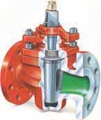
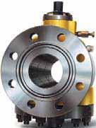
51 The Production Range Two Way Standard Type Two Way Pressure Balanced Type Two Way Pressure Balanced Type with Stem Extension Two Way LGC Pressure Balanced Full Bore Type Two Way with PTFE Sleeve 3S Series Actuators Availability Two Way Pressure Balance Type Gear Operated 51


52

53 GALLI&CASSINA in the World: Our products are being used in themost important Plants and Gas Pipelines all over the world. Galli&Cassina Plug Valves are used in the most important hydrocarbon plants and gas pipelines all over the world. For over 70 years Galli&Cassina has been committed to provide service to the end-users with a full range of products ensuring total customer s satisfaction. Galli&Cassina is represented by sales offices worldwide and you are requested to contact our main office in Italy for more details.


54 AdverTime-MI G&C B (U.S.A) Engineering, Sales and Service: G&C Americas Inc. Galli&Cassina USA Champion Forest Dr. Unit 701, Houston, Texas, 77069, USA Phone (+1) Mobile (+1) (24/7) Web:
GALLI&CASSINA. Plug Valves. Conical
 Conical Plug Pressure Balanced Type UPPER HOLE LOWER HOLE The Pressure Balanced Plug Contains 2 Holes: The Upper Holes Connects the Plug Port with the Area Above Plug. The Lower hole Maintains Pressure
DOUBLE BLOCK & BLEED PLUG VALVES
 DOUBLE BLOCK & BLEED PLUG VALVES Galli&Cassina Profile TORINO Galli&Cassina is a prominent Italian Company mainly involved in the manufacture of a complete range of Lubricated Plug Valves. The company
Guide Valve Limited 1
 Guide Valve Limited 1 COMPANY PROFILE Guide Valve Limited, established in 1981 with its headquarters in Canada, specializes in the manufacturing of bolted body trunnion mounted ball valves. Brand named
TRUNNION BALL VALVES. TBV 7.10
 TRUNNION BALL VALVES WWW.VALVE.COM TBV 7.10 ABOUT US Our mission at Universal Flow (), is to provide a quality product at a competitive price and to meet the needs and requirements of our customers in
PBV s Engineering Excellence At Work
 PBV s Engineering Excellence At Work The PBV Series 5700/6700 Three-Piece, Side-Entry, Trunnion Ball Valve 2"- 56" ANSI Class 150/300,600,900,1500 & 2500 In Full And Standard Port PBV trunnion ball valves
Engineered Valves For Pipeline Service Application
 Page 1 TRUNNION MOUNTED BALL VALVES TM SERIES Engineered Valves For Pipeline Service Application Valves for oil & gas pipelines and other industrial applications Flanged or Butt Weld ANSI Class 150 thru
Forged 3 Piece Trunnion Mounted Ball Valves Series PL
 Forged 3 Piece Trunnion Mounted Ball Valves Series PL Construction: 3 piece bolted side entry Trunnion housings 4 Trunnion retainer plates 6 Standard single piece seating SPE & DPE Special scraping 3 piece
PRODUCT NEWS CAT.NO.-70 KPC CORPORATION FLOW CONTROL DIVISION
 PRODUCT NEWS CAT.NO.-70 CERTIFIED TO ISO 9001 KPC CORPORATION FLOW CONTROL DIVISION Internal or External Trunnion Design KPC Construction Features BODY GASKET The tongue - and - groove body gasket maximizes
High performance valves for high level expectations PROUDLY MADE IN ITALY
 High performance valves for high level expectations Location ERREESSE, established in 2004, is a manufacturing company based in the Northern Italy, Grignasco, a nice town in the green Valsesia (Sesia Valley),
MSA, a.s., is an important manufacturer of industrial valves from the Czech Republic, Europe. The company manufactures and sells wide range of
 API Program MSA, a.s., is an important manufacturer of industrial valves from the Czech Republic, Europe. The company manufactures and sells wide range of industrial valves for transport and processing
International Standard Valve, Inc. Trunnion Mounted Ball Valve
 International Standard Valve, Inc. TM ISV Series BT3E & BT3G-International Trunnion Mounted Ball Valve Forged Construction 2 through 56 ASME Class 150-2500 Bolted or Welded Body Flanged & Weld Ends API
STANDARDS and SPECIFICATIONS
 ANSI (American National Standards Institute) ANSI B31.4 - Liquid petroleum transportation piping system. ANSI B31.4 - Gas transmission and distribution piping system. API (American Petroleum Institute)
Fully Welded Ball Valves
 Ball Valves Ball Valves FULLY WELDED type ball valves are cut off devices suitables for use both on natural gas distribution network and for liquid service when high performance on thightness and low pressure
Trunnion Ball Valves
 Trunnion Ball Valves Trunnion Classification and Operating range TRUNNION type ball valves are cut off devices suitables for use both on natural gas distribution network and for liquid service when high
TM SERIES Engineered Valves For Pipeline Service Application
 Tech Bulletin Page 0-1 Page 1 TRUNNION MOUNTED BALL VALVES TM SERIES Engineered Valves For Pipeline Service Application Valves for oil & gas pipelines and other industrial applications Flanged or Butt
International Standard Valve, Inc. Trunnion Mounted Ball Valve
 International Standard Valve, Inc. TM ISV Series BT3EU, BT3E & BT3G Trunnion Mounted Ball Valve Forged Construction 2 through 56 ASME Class 150-2500 Bolted or Welded Body Flanged & Weld Ends API 6D Fire
Gate Valve (Model 1000)
") Gate Valve (Model 1000) s: - 2 to 24 (50mm to 600mm) Rating: - Class 150 to Class 2500 Cast Steel Valves Flange End But-Weld End Information:- www.invacovalves.com sandesh@invacovalves.com invacovalves@gmail.com
Gate Valve (Model 1000) s: - 2 to 24 (50mm to 600mm) Rating: - Class 150 to Class 2500 Cast Steel Valves Flange End But-Weld End Information:- www.invacovalves.com sandesh@invacovalves.com invacovalves@gmail.com
VALVITALIA - DELTA PLUG VALVE CATALOGUE TYPE 24/28 SERIES & 22
 VALVITALIA - DELTA PLUG VALVE CATALOGUE TYPE 24/28 SERIES & 22 Complete valve packages including: Actuation and controls Stem extensions NDE testing Special coatings Subsea service DELTA Valves, part of
Introduction Certifications References Standards Ball Valves Trunnion Mounted Ball Vaves Product Range...
 CATALOGUE CONTENTS Introduction... 3 Certifications...4-5 References Standards... 6 Ball Valves... 7 Trunnion Mounted Ball Vaves... 8 Product Range... 9 Available Design Options... 10 Quality & Testing...
RAIMONDI TRUNNION MOUNTED FULLY WELDED BALL VALVE FIGURE 5600
 The ideal valve to minimize any risk of fugitive emissions from flanges in the natural gas and oil industry FEATURES GENERAL APPLICATION The Fig. 5600 valves have been designed for gas transportation and
Trunnion Ball Valves
 Ball Valves Ball Valves TRUNNION type ball valves are cut off devices suitables for use both on natural gas distribution network and for liquid service when high performance on thightness and low pressure
SVF FLOW CONTROLS. Series # Flanged Standard Port Fire Safe / API th Edition. Performance Engineered I N C O R P O R A T E D
 Series 41 150# Flanged Standard Port Fire Safe / API-607 4 th Edition 1 PIECE REDUCED PORT BALL VALVE UNITS = INCHES SIZE CLASS 150 WEIGHTS L H W 1 1/2 11 6.50 3.86 9.06 2 21 7.01 4.65 9.06 3 40 7.99 5.98
GROVE B4, B5 and B7 Side-entry Ball Valves
 GROVE B4, B5 and B7 Side-entry Ball Valves Table of Contents GROVE B4, B5 and B7 SIDE-ENTRY BALL VALVES Features and Benefits Applications...1 GROVE B4 Design Features...2 Materials Specifications...4
DIPV Double Isolation Plug Valve. Double Block & Bleed Plug Valve
 DIPV Double Isolation Plug Valve Double Block & Bleed Plug Valve Double Isolation Plug Valve Contents Introduction pages 3 & 4 Typical Installations pages 5 & 6 Range page 6 Main Features page 7 Figure
ECOLINE GTC Type Series Booklet
 Gate Valve ECOLINE GTC 150-600 Class 150-600 NPS 2''-36'' Cast Steel / Stainless Steel Bolted Bonnet Flanged Ends Type Series Booklet Legal information/copyright Type Series Booklet ECOLINE GTC 150-600
Trunnion Mounted Ball Valves
 Trunnion Mounted Ball Valves CONTENTS Product Coding for KITZ Trunnion Mounted Ball Valves 2 Soft seated 2 Metal seated 2 Soft Seated 3-Piece Body Trunnion Mounted Ball Valves T60S Series (1) 3 Component
Trunnion Mounted Ball Valves
 Trunnion Mounted Ball Valves CONTENTS Product Coding for KITZ Trunnion Mounted Ball Valves 2 Soft seated 2 Metal seated 2 Soft Seated 3-Piece Body Trunnion Mounted Ball Valves T60S Series (1) 3 Component
FASANI PRESSURE SEAL CAST GLOBE VALVES - STYLE B Y AND T PATTERN
 A wide range of globe valves specifically designed for high pressure and high temperature applications, where low pressure loss is required. FEATURES GENERAL APPLICATION Our pressure seal globe valves
Contents. Dimensions and weights
 G4N Gate Valves Through-conduit, double block-and-bleed slab gate valves with fully protected seat faces for long-lasting, drop-tight shutoff in liquid pipelines Contents General information 3 Standard
E N G I N E E R E D V A L V E S. B4, B5 & B7 Side Entry Ball Valves GROVE
 B4, B5 & B7 Side Entry Ball Valves TABLE OF CONTENTS B4 B5 B7 SIDE ENTRY BALL VALVE FEATURES AND BENEFITS General Information 1 B4 Design Features 2 & 3 Valve Assembly and Cross Section 4 Dimensions and
technical description:
 The gate valves are used as the closing valves for: - noncorrosive fluids - saturated steam - oil - air - petroleum and petroleum products Operating parameters are in accordance with the standard ASME
PRODUCT OVERVIEW. Our BDB (Bolted Body) and BW3 (Fully Welded Body) trunnion-mounted ball valves are designed and manufactured
 and BW3 (Fully Welded Body) trunnion-mounted ball valves are designed and manufactured") PRODUCT OVERVIEW For over 30 years, FluoroSeal has been manufacturing and customizing a wide range of valves, and accessories for many industries including Oil & Gas, Petrochemical, Chemical, Mining, Pharmaceutical,
PRODUCT OVERVIEW For over 30 years, FluoroSeal has been manufacturing and customizing a wide range of valves, and accessories for many industries including Oil & Gas, Petrochemical, Chemical, Mining, Pharmaceutical,
GA-1601B (EN) GATE VALVE
 GATE VALVE") GA101B (EN) GATE VALVE ABOUT US FBV Inc. is an ISO 9001 certified company specializing in manufacturing industrial valves including ball valves, gate valves, globe valves, check valves, plug valves and
GA101B (EN) GATE VALVE ABOUT US FBV Inc. is an ISO 9001 certified company specializing in manufacturing industrial valves including ball valves, gate valves, globe valves, check valves, plug valves and
Forged 3 Piece Trunnion Mounted Ball Valves Series MS
 Forged 3 Piece Trunnion Mounted Ball Valves Series MS Construction: 3 piece bolted side entry Trunnion housings 4 Trunnion retainer plates 6 Metal Seated Chrome carbide and tungsten carbide trims Uni-directional
GWC Italia. Proven technology for individual valve solutions worldwide FSV-1005
 GWC Italia Proven technology for individual valve solutions worldwide forged STEEL VALVES GATE, GLOBE & CHECK FSV-1005 2 GWC ITALIA Proven technology for individual valve solutions worldwide w w w. g w
Check Valve (Model 6000)
") Check Valve (Model 6000) s: - 2 to 24 (50mm to 600mm) Rating: - Class 150 to Class 2500 Cast Steel Valves Flange End But-Weld End Information:- www.invacovalves.com sandesh@invacovalves.com invacovalves@gmail.com
Check Valve (Model 6000) s: - 2 to 24 (50mm to 600mm) Rating: - Class 150 to Class 2500 Cast Steel Valves Flange End But-Weld End Information:- www.invacovalves.com sandesh@invacovalves.com invacovalves@gmail.com
The globe valves are used as a closing valve for: - noncorrosive fluids - saturated steam
 The globe valves are used as a closing valve for: - noncorrosive fluids - saturated steam - oil - air - petroleum and petroleum products The Characteristics of working conditions: pressure dependency on
Butterfly Valve. Resilient or Sleeved (Model 9400) Damper or Clearance (Model9300)
 Damper or Clearance (Model9300)") Butterfly Valve Resilient or Sleeved (Model 9400) Damper or Clearance (Model9300) Sizes: - 2 to 120 (50mm to 3000mm) Rating: - Class 150 & PN16 Wafer Type Lug Type Flanged End Information:- www.invacovalves.com
Butterfly Valve Resilient or Sleeved (Model 9400) Damper or Clearance (Model9300) Sizes: - 2 to 120 (50mm to 3000mm) Rating: - Class 150 & PN16 Wafer Type Lug Type Flanged End Information:- www.invacovalves.com
WKM 320F. Flanged floating ball valves
 WKM 20F Flanged floating ball valves Contents WKM 20F Flanged Floating Ball Valves Features and benefits.................................................................... Exploded views and specifications....................................................5
AIL METSEAL Butterfly Valves
 AIL METSEAL Butterfly s The AIL METSEAL Butterfly is a high performance valve which is used for positive isolation in Power Generation, Petroleum Refining, Oil and Gas Production, Chemical, Petrochemical
Proudly represented exclusively by: Flowlink Enterprises Pty Ltd. Phone
 Proudly represented exclusively by: Flowlink Enterprises Pty Ltd sales@flowlinkepl.com.au www.flowlinkepl.com.au Phone 1300 086 499 PREAMBLE This technical document contains proprietary information belonging
The Company LCM ITALIA, which is part of CHERO group, was established
 Contents oreword Applicds Quality Assurance and Certification Technical Features of Floating Ball Valve Assembly Drawing of Floating Ball Valve Standard Materials selection of Floating Ball Valve Production
SOFT SEATED TRUNNION MOUNTED BALL VALVES CSTS SERIES
 CSTS SERIES Quality equates to the sum of Applied Science Serving the most rugged applications in the Western Canadian Sedimentary Basin Brochure CSTS Series February 2016 CSC Valves Canada Inc. operates
GL-1601C (EN) GLOBE VALVE
 GLOBE VALVE") GL1C (EN) GLOBE VALVE ABOUT US FBV Inc. is an ISO 9001 certified company specializing in manufacturing industrial valves including ball valves, gate valves, globe valves, check valves, plug valves and
GL1C (EN) GLOBE VALVE ABOUT US FBV Inc. is an ISO 9001 certified company specializing in manufacturing industrial valves including ball valves, gate valves, globe valves, check valves, plug valves and
Through Conduit Gate Valves Slab & Expanding
 Through Conduit Gate Valves Slab & Expanding Through Conduit Slab Gate valve Slab Gate Valves are manufactured with a full bore port, rising stem OS&Y and with floating seats and gate, pressure energized,
40T Series TRUNNION MOUNTED BALL VALVES
 40T Series TRUNNION MOUNTED BALL VALVES Specialist in Quality and Reliability since mid sixty s. RBR was founded in 1964 and it has always been acknowledged worldwide as one of the leading manufactures
Bolted Three Piece Forged Steel TRUNNION BALL VALVE
 Bolted Three Piece Forged Steel TRUNNION BALL VALVE TABLE OF CONTENTS Manufacturing range Key features & benefi ts Cross sectional drawings Sizes & dimensions Top works dimensions Actuation capabilities
TRUNNION MOUNTED BALL VALVES
 TRUNNION MOUNTED BALL VALVES COMPANY PROFILE The company ARMATURY Group a.s. is a leading Czech manufacturer and distributor of industrial valves, fittings and control systems for valves. The annual production
Ball Valves. DHV Industries, Inc. DHV Valve Company Inc Pegasus Drive Bakersfield, CA U.S.A. Phone: (661) Fax: (661)
 Fax: (661)") 3451 Pegasus Drive Bakersfield, CA 93308 U.S.A. Call Toll Free: (877) DHV-USA1 Phone: (661) 392-8948 Fax: (661) 392-8947 E-mail: sales@dhvindustries.com Website: www.dhvindustries.com DHV Valve Company
3451 Pegasus Drive Bakersfield, CA 93308 U.S.A. Call Toll Free: (877) DHV-USA1 Phone: (661) 392-8948 Fax: (661) 392-8947 E-mail: sales@dhvindustries.com Website: www.dhvindustries.com DHV Valve Company
Triple-offset Butterfly Valves
 Triple-offset Butterfly Valves ASME Class 150 to 1500 3 to 100 (80 mm to 2500 mm) API 609 L&T Valves L&T Valves is a wholly owned subsidiary of Larsen & Toubro. Backed by a heritage of excellence that
ANSI GATE, GLOBE AND CHECK VALVES & STRAINERS
 ANSI GATE, GLOBE AND CHECK VALVES & STRAINERS INDEX 2 8 16 20 32 36 44 50 54 58 62 66 78 THE COMPANY CAST GATE VALVES CAST GATE VALVES PRESSURE SEAL CAST GLOBE VALVES CAST GLOBE VALVES PRESSURE SEAL CAST
VANESSA SERIES 30,000 TRIPLE OFFSET VALVES* BASIC CONFIGURATION
 * BASIC CONFIGURATION With a robust integral-to-body valve seat and optimized seating angles, this valve is capable of handling isolation and process control through multiple functionalities FEATURES GENERAL
GWC Italia. Proven technology for individual valve solutions worldwide API 6D THROUGH CONDUIT SLAB & PARALLEL EXPANDING GATE VALVES PGV-1002
 GWC Italia Proven technology for individual valve solutions worldwide API 6D THROUGH CONDUIT SLAB & PARALLEL EXPANDING GATE VALVES PGV-1002 GWC ITALIA Proven technology for individual valve solutions worldwide
TECHNICAL BULLETIN. Serck Audco TIPV- Twin Isolation Plug Valve. Experience in Motion SRENTB (A4) 02/14
 02/14") TECHNICAL BULLETIN Serck Audco TIPV- Twin Isolation Plug Valve SRENTB0005-03 (A4) 02/14 Experience in Motion Experience in Motion Contents Introduction.... 3 Design Features.... 4-8 Typical Installations....
TECHNICAL BULLETIN Serck Audco TIPV- Twin Isolation Plug Valve SRENTB0005-03 (A4) 02/14 Experience in Motion Experience in Motion Contents Introduction.... 3 Design Features.... 4-8 Typical Installations....
TECHNICAL BULLETIN. Serck Audco Iron Taper Plug Valve. Experience in Motion Experience in Motion SRENTB A4 02/17
 TECHNICAL BULLETIN Serck Audco Iron Taper Plug Valve SRENTB0002-04 A4 02/17 Experience in Motion Experience in Motion Range and Index Regular Pattern Short Pattern Standard Type Screwed ends/ Flanged Inverted
COMPANY PROFILE 0045
 0045 COMPANY PROFILE INTRODUCTION TO THE COMPANY THE MICROFINISH WAY Microfinish Valves Pvt. Ltd. is a privately owned and managed company specializing in industrial valves for energy, process, and natural
technical description:
 The steel flanged and welded swing check valves are the pipeline valves, preventing automatically a working medium from the back flow. They are used for: - noncorrosive fluids - water - steam - oil - petroleum
THROUGH CONDUIT VALVES TECHNICAL CATALOGUE
 SITINDUSTRIE VALVO VALVES THROUGH CONDUIT VALVES Ed. 01/DIC-2004 SITINDUSTRIE reserves the right to change, without notice, 1/14 SITINDUSTRIE TRIE VALVE DIVISION We are pleased to introduce you to the
TECHNICAL BULLETIN. Serck Audco DIPV - Double Isolation Plug Valve. Experience in Motion FCD SRENTB A4 02/17
 Serck Audco DIPV - Double Isolation Plug Valve FCD SRENTB0001-04-A4 02/17 TECHNICAL BULLETIN Experience in Motion 2 Serck Audco DIPV Double Isolation Plug Valve FCD-SRENTB0001-04-A4 02/17 Contents Introduction....
GWC Italia. Proven technology for individual valve solutions worldwide HIGH PERFORMANCE BUTTERFLY VALVE HPB-1003
 w w w. g w c i t a l i a. c o m GWC Italia Proven technology for individual valve solutions worldwide HIGH PERFORMANCE BUTTERFLY VALVE HPB-1003 1 1 GWC ITALIA Proven technology for individual valve solutions
Triple Offset Valves
 Triple Offset Valves FLOWSEAL MS Value Statement For the harsh conditions of critical process applications, steam isolation, high cycle frequency, and temperature extremes, the Flowseal MS triple-offset
Mars Series 88 Stainless Steel Reduced Bore Or Full Bore Ball Valve, Lever Operated, BSP Or Socket Weld Ends
 SPECIFICATION See our full range online at: www.vip-ltd.co.uk Mars Series 88 Stainless Steel Reduced Bore Or Full Bore Ball Valve, Lever Operated, BSP Or Socket Weld Ends VIP Product Codes 04/0466 (BSP)
TRUNNION MOUNTED BALL VALVES API 6D & API 6A. Side_Entry Ball Valve SE type
 TRUNNION MOUNTED BALL VALVES API 6D & API 6A Side_Entry Ball Valve SE type Stem Stem Seals Body / Closure Gasket Ball Seat Seat Seal Side_Entry Ball Valve SE type TECHNICAL DESCRIPTION Description: ON/OFF
D I S T R I B U T E D V A L V E S. Super G Lubricated-Non-Lubricated Plug Valve TEXSTEAM
 Super G Lubricated-Non-Lubricated Plug Valve SUPER G EXCLUSIVE FEATURES Built and tested in accordance with API 6A, API 6D & B16. Lubricated and non-lubricated in same valve. Use it either way Metal-to
RAIMONDI. High pressure forged globe valves to guarantee the pressure envelope integrity on harsh services.
 Fig. 6022-6025 RAIMONDI High pressure forged globe valves to guarantee the pressure envelope integrity on harsh services. Features Forged body materials of highest quality, all in compliance with ASME
METSO NELES HIGH PERFORMANCE VALVE, METAL SEATED SERIES BW
 METSO NELES HIGH PERFORMANCE VALVE, METAL SEATED SERIES BW Neles BW series metal seated high performance butterfly valve with one piece body design, for both control and tight shut-off applications. Multiple
MV1. Malaysia s 1st API 6D Ball & Gate Valves & Actuators Manufacturer. Cert. No License No. 6D-0840
 MV1 Cert. No. 224939 License No. 6D-0840 0062 Malaysia s 1st API 6D Ball & Gate Valves & Actuators Manufacturer INTRODUCTION MIR VALVE Sdn. Bhd. (MIR VALVE) was incorporated on 27 December, 2006, obtained
GWC Italia. Proven technology for individual valve solutions worldwide API 6D THROUGH CONDUIT SLAB & PARALLEL EXPANDING GATE VALVES PGV-1002
 GWC Italia Proven technology for individual valve solutions worldwide API 6D THROUGH CONDUIT SLAB & PARALLEL EXPANDING GATE VALVES PGV-1002 2 GWC ITALIA Proven technology for individual valve solutions
PETRO VALVES. Gate Globe Check VALVE CATALOGUE. Subsidiary of Petro Power UK
 PETRO VALVES Gate Globe Check VALVE CATALOGUE Subsidiary of Petro Power UK 2 PETRO VALVES The company 4 GATE VALVES BOLTED BONNET from Class 150 up to Class 2500 from 2 up to 36 PRESSURE SEAL from Class
Keystone WINN Hi-Seal High Performance Butterfly Valve
 m o Keystone WINN Hi-Seal High Performance Butterfly Valve Hi-Seal, high performance butterfly valves offer efficient, bi-directional sealing across a wide spectrum of service conditions Features Positive
Full Opening Swing CHECK VALVE - API 6D
 Full Opening Swing CHECK VALVE - API 6D Table of Contents: Manufacturing Range 3 Features & Benefits 4 Drawings 6 Sizes & Dimensions 8 Pressure / Temperature Reference 14 Flow Coefficients (Cv) 14 How
Ball Valves. Quality Valves at Low Cost
 Ball Valves Quality Valves at Low Cost Table of Contents B Series, 2, 3 PC Ball Valves Part Numbering System...3 B0: 2 PC, 000 WOG, 36SS... 4 B02: 2 PC, 2000/0 WOG, 36SS... 4 B03: 2 PC, 000 WOG, 36SS Direct
FloCheck is a precision engineered, twin plate check valve suitable for product or service lines, wherever non-return protection is required.
 FloCheck is a precision engineered, twin plate check valve suitable for product or service lines, wherever non-return protection is required. Features Twin plate, flat seat design for enhanced sealing.
CAMERON Fully Welded Ball Valves
 CAMERON Fully Welded Ball Valves Engineered for heavy duty, limited maintenance performance, with the strength of forged components and a lightweight, compact, spherical design Table of Contents CAMERON
TECHNICAL BULLETIN. Serck Audco Super-H. Experience in Motion SRENTB A4 02/17
 TECHNICAL BULLETIN Serck Audco Super-H SRENTB0004-04 A4 02/17 Experience in Motion Contents Super-H Design... 3 Super-H Features Explained... 4 Why Select a Plug Valve?... 5 Why Select a Super-H?... 5
TECHNICAL BULLETIN. Valbart TM Through conduit slab gate valve. Experience in Motion FCD VBENTB A4 - (9/16)
") Valbart TM Through conduit slab gate valve TECHNICAL BULLETIN FCD VBENTB1013-01-A4 - (9/16) Experience in Motion Valbart Through Conduit Slab Gate Valve The Valbart TCSGV is a fabricated body through conduit
Valbart TM Through conduit slab gate valve TECHNICAL BULLETIN FCD VBENTB1013-01-A4 - (9/16) Experience in Motion Valbart Through Conduit Slab Gate Valve The Valbart TCSGV is a fabricated body through conduit
TECHNICAL BULLETIN. Serck Audco Full Bore Super-H Plug Valve for Slurry and Piggable Applications. Experience in Motion SRENTB A4 02/17
 Serck Audco Full Bore Super-H Plug Valve for Slurry and Piggable Applications SRENTB0007-04 A4 02/17 TECHNICAL BULLETIN Experience in Motion Contents Full Bore Super-H Design...4 Super-H Features Explained...5
PBV Ball Valves. Two Piece Flanged Trunnion Supported Ball Valves. REQUEST A QUOTE SCHEDULE SERVICES
 PBV Ball Valves Two Piece Flanged Trunnion Supported Ball Valves REQUEST A QUOTE sales@dkamans.com SCEDUE SERVICES 562-529-8400 WWW.DKAMANS.COM Manufacturer of Quality Valve Products Around the Globe At
Triad Series. 3 Piece Ball Valves Full Port: 1 /4-4 Standard Port: 3 /4-2 1 /2. Model FP - Full Port Model SP - Standard
 A Bray High Performance Company A Subsidiary of BRAY INTERNATIONAL, Inc. 3 Piece Ball Valves Full Port: 1 / - Standard Port: 3 / - 1 / Triad Series Model FP - Full Port Model SP - Standard Port Flow-Tek
ALC-3 BUTTERFLY VALVES NOMINAL PRESSURE NOMINAL SIZE MATERIALS CONNECTIONS DESIGN. ANSI Class PN DN
 BUTTERFLY VALVES ALC-3 NOMINAL PRESSURE ANSI Class 150-600 PN 10-100 NOMINAL 2-80 DN 50-2000 MATERIALS Cast Iron Carbon Steel Low Alloy Steel CONNECTIONS Wafer Lugged Flanged Butt Weld DESIGN Eccentric
BS EN ISO 9001 FM Worcester Controls 5 Series BS 5351 Approved Flanged Ball Valves
 BS EN ISO 9001 0086 as FM 00707 Worcester Controls BS 5351 Approved Flanged Ball Valves Worcester is proud to announce the introduction of its new 519/529 range of ball valves which replaces the DN 15-50
CAST TRUNNION BALL VALVE
 CAST TRUNNION BALL VALVE ATLAS SERIES BEHIND THE NAME With a renewed focus on product leadership through innovation and quality, C&C is your world class provider of flow solutions. 2 Atlas, a Titan known
SECTION S DOUBLE OFFSET HIGH PERFORMANCE BUTTERFLY VALVES
 SECTION S DOUBLE OFFSET HIGH PERFORMANCE BUTTERFLY VALVES DESCRIPTION STANDARD COMPLIANCE/CERTIFICATIONS S-2 ADVANTAGES S-3 PAGE SOFT SEAT EXPLODED VIEW S-4 FIRE SAFE SEAT EXPLODED VIEW S-5 METAL SEAT
CAST STEEL GATE VALVE
 CAST STEEL GATE VALVE DESIGN CHARACTERISTICS OF API00 CAST STEEL GATE VALVE The design of thrust bearing makes valve opened easily and flexibly. Handwheel Nut Handwheel Stem Nut Retainer Stem Nut Lubricating
Three Piece Forged Trunnion Mounted Ball Valve
 International Standard Valve, Inc. 7111 Perimeter Park Drive, Bldg 320 Houston, Texas 77041 713-983-7600 TM Three Piece Forged Trunnion Mounted Ball Valve 2 through 56 ASME Class 150-1500 Bolted or Welded
butterfly valves high performance TRIPLE OFFSET HP-TRI REV0
 high performance EXECUTION 1st OFFSET 2nd OFFSET 3rd OFFSET The BELVEN-TRI series incorporate triple offset disc configuration. With this configuration the disc seal makes contact with body seat, only
Double Block and Bleed Plug Valves
 Double Block and Bleed Plug Valves ASME Class 150 to 600 50 mm to 1050 mm (2 to 42 ) API 6D L&T Valves L&T Valves is a wholly owned subsidiary of Larsen & Toubro. Backed by a heritage of excellence that
Design & Technology in Valves
 Design & Technology in Valves Ibor has been involved in many large international projects with the world s leading EPC Company overview Ibor manufacture Ball valves, Butterfly valves, Gate Valves, Check
TECHNICAL BULLETIN Top Entry Cryogenic Ball Valve Standard & Full Port
 TECHNICAL BULLETIN Top Entry Cryogenic Ball Valve Standard & Full Port ROCKER PACKING GLAND 36 stainless steel, rocker shaped packing gland compensates for uneven adjustment of gland bolts. ISO 5 MOUNTING
SECTION S - DOUBLE OFFSET HIGH PERFORMANCE BUTTERFLY VALVES TABLE OF CONTENTS. Standard Compliance/Certifications S-2 Advantages S-3
 SECTION S - DOUBLE OFFSET HIGH PERFORMANCE BUTTERFLY VALVES TABLE OF CONTENTS DESCRIPTION Standard Compliance/Certifications S-2 Advantages S-3 PAGE Soft Seat Exploded View S-4 Fire Safe Seat Exploded
PRESSURE BALANCED TYPE LUBRICATED PLUG VALVES General Index
 General Index Range and Index...1 Figure Numbering...2 Materials...3-4 Pressure Testing...5 Installation, Marking and Identification...6-7 Desgin Features...8-9 Stress Analysis to the body...10 Components
BALL VALVES 4Evergreen Valve
 BALL VALVES 4Evergreen Valve 4E represents Excellent quality, Excellent delivery, Excellent service and all at an Excellent price. 4E valve was founded by a group of enthusiastic people with more than
CLASS 150 & 300 REDUCED BORE BALL VALVES
 CLASS 150 & 300 REDUCED BORE BALL VALVES AGA - APPROVED MANUAL & AUTOMATIC FLANGED BALL VALVES - EMICO FIGURE NUMBERING SYSTEM E A 503 507 F C X EMICO BRAND VALVE SYMBOL SERIES NUMBER BODY MATERIAL A:
30 Years of Innovation
 C-BV6 Ball Valves 30 Years of Innovation OMB is a family owned and managed business founded by Mr. Roberto Brevi in 1973. His goal was to build a company that would specialize in the manufacturing of forged
VALVES & MEASUREMENT. TEXSTEAM Super G Plug Valves TEXSTEAM
 TEXSTEAM Super G Plug Valves TEXSTEAM 2 TEXSTEAM TABLE OF CONTENTS Introduction... 4 Design Standards... 5 Parts List... 6 Accessories and Repair Kits... 7 Reduced Port Dimensions and Weights... 8 Full
Gate, Globe & Check Valves Corrosion-resistant
 Gate, Globe & Check Valves Corrosion-resistant ASME Class 0 to 00 " - " (0 mm - 00 mm) API 0, ASME B. L&T Valves Trusted by the industry for over five decades, L&T Valves offers innovative products and
High Performance Butterfly Valves
 Tech Bulletin Page 500-11 MAX SEAL HP SERIES High Performance Butterfly Valves Available with Soft and Metal Seating MODEL BL630 Size Range 2 thru 24, optional thru 120 ANSI Class 150//600/900 20 Lug 6
Series Direct contact and metal-to-metal seating makes the T-pattern globe stop valve ideal for most shut-off applications.
 7 YARWAY Hancock T-Pattern Globe valves Direct contact and metal-to-metal seating makes the T-pattern globe stop valve ideal for most shut-off applications Features Heavy integral stellite hardfacing on
M Series Floating Metal Seat Ball Valve
 M Series Floating Metal Valve 1 M Series Floating Metal Valve Full Bore Two-piece Flanged Ends ANSI 150/300/600LB The A-T Controls M Series metal seat ball valve is designed for use in severe services
DESFLEX COMPACT FLANGES
 DESFLEX COMPACT FLANGES DESFLEX COMPACT FLANGES The first original Compact Flange designed in full accordance with ASME ANSI PD 5500, Type Approved & Fire Tested. Offering weight savings of up to 88% when