0810C. Valve Group Series. Farris Engineering Pressure Relief Valves
|
|
|
- Abraham Fitzgerald
- 5 years ago
- Views:
Transcription


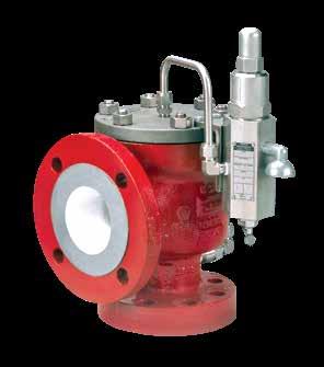
1 0810C Valve Group 3800 Series Farris Engineering Pressure Relief Valves
2 Table of Contents Selection Table Matrix...1 Principles of Operation Numbering System Features/Bill of Materials Main Valve Snap Acting Pilot Control Modulating Pilot Control HPCM7 Modulating Control Selection Tables API Non Standard API...16 Full Port...17 Capacity Tables US Units Air Capacities: 10% Overpressure for API...18 Air Capacities: 10% Overpressure for Full Port...19 Steam Capacities: 10% Overpressure for API...20 Steam Capacities: 10% Overpressure for Full Port...20 Water Capacity: 10% Overpressure for API...21 Capacity Tables Metric Units Air Capacities: 10% Overpressure for API...22 Air Capacities: 10% Overpressure for Full Port...23 Steam Capacities: 10% Overpressure for API...24 Steam Capacities: 10% Overpressure for Full Port...24 Water Capacity: 10% Overpressure for API...25 Sizing Information...26 Sizing Factors for Vapors and Gases...27 Dimensions and Weights for API Nozzle Design Dimensions and Weights for Full Port Design...30 Optional Accessories Conversion Factors...36 Piloting the Way to Precision Control This catalog is provided to aid in the proper selection of a Farris 3800 Series. Farris 3800 Series valves feature an innovative, integrally cast, flanged body with a semi-nozzle design. Series 3800 valves are self-contained units actuated by either the snap-acting or modulating style pilot controls. Valves in this series are certified under Section VIII of the ASME Code for Air, Gas, Vapor, Steam and Liquid Service Series valves are available in API Orifice sizes D through T as well as full port models. Series 3800 valves offers raised face or ring joint inlet flanges from 150 through 2500 ASME classes with 150, 300 and selected 600 class outlets. Standard options support applications in pressures range from 15 to 6 psig with temperatures of -450 F to 450 F. For higher temperature and pressure requirements, please consult the Factory. All Series 3800 valves have non-flowing pilot controls. Standard materials of construction include a carbon steel main valve body with 316 stainless steel trim and all 316 stainless steel pilot control. The main valve is also available in optional materials in a full 316 stainless steel, NACE, Monel, Hastelloy, Duplex with other materials available upon request. Viton soft goods are standard in both pilot control and main valves. Buna-N, neoprene, ethylene propylene, silicone, PTFE and Kalrez soft goods are available as options; contact Factory for more information. Sizing software and support is available at Viton and Kalrez are registered trademarks of DuPont Performance Elastomers. PTFE is a registered trademark of the DuPont Corporation. Monel is a registered trademark of Inco Alloys International, Inc. Hastelloy is a registered trademark of Haynes International, Inc. Warranty All products manufactured by Farris Engineering are warranted free of defects in material and workmanship when used within the range recommended for a period of one year after installation or eighteen months from delivery. When authorized, any defective product may be returned to the factory and if found defective will be repaired or replaced free of charge, solely at the discretion of Farris Engineering, ex-works our factory. No charge for labor or other expense incurred will be allowed, as the liability of Farris Engineering is measured by the refund price of the defective product only. All warranties are based on the product being used within the range recommended and does not cover damages or defects due to normal wear and tear, misuse, alteration or neglect. The purchaser shall determine the suitability of the product for use and assumes all risks and liabilities in connection therewith. This warranty does not cover the performance of valves tested at site on test equipment that is not to the same technical standard as that used by the manufacturer.
3 Selection Table Matrix 3800 Series Pilot Control Application Summary Type of Actuation PCF5 (2) PCL (3) PCM (4) PCMS (5) HPCM (6) HPCM (7) Snap-Acting ü ü Modulating ü ü ü ü Blowdown Set Pressure Ranges psig (barg) Fluid Services Temp. Range F ( C) Soft Goods (O-Rings) F ( C) Fluorocarbon (Viton) Ethylene Propylene (EPDM) Nitrile (Buna) Aflas Kalrez Kalrez Steam Adjustable ü Non-adjustable ü ü ü ü ü 15 to (1.03 to 3) ü ü ü ü 741 to (51.1 to.1) ü ü ü 2221 to 6 (.2 to.5) ü ü ü Air/Gas/Vapor ü ü ü ü ü Liquid ü ü ü ü ü Steam -50 to 500 (-45 to 260) ü ü ü ü ü ü -450 to -51 (-267 to -46) ü -20 to 450 (-29 to 232) ü ü ü ü ü ü -65 to 250 (-54 to 121) ü ü ü ü ü ü -55 to 225 (-48 to 107) ü ü ü ü ü ü -20 to 450 (-29 to 232) ü ü ü ü ü ü 0 to 500 (-18 to 260) ü ü ü ü ü 212 to 500 (100 to 260) ü ü Soft Goods Disclaimer All PORVs use soft goods for their seats and seals. In selecting a soft good, please note the following guidelines: The main valve and pilot control soft goods selection is based on meeting the set pressure and temperature ranges shown as well as being chemically compatible with the process fluid. The soft goods selected should not exceed the above limits. For most applications both the operating and relieving temperatures should fall within the ranges shown. Where the sole relieving scenario is external fire, the relieving temperature may be ignored as long as the operating temperature falls within the range of the elastomer selected. Because of the wide variety of fluids and process conditions used in the process industry, it is the customer s responsibility to select the proper soft goods material for each specific application. 1


4 Principles of Operation Snap Acting Closed Valve Position The pilot control valves use system pressure to keep the main valve closed. System pressure is transmitted through the pressure pickup from the inlet of the main valve, through the pilot control and into the dome of the main valve. The system pressure exerts force upon the top of the piston in the dome, holding the piston firmly against the seat on the nozzle in the main valve. The surface area of the piston in the dome of the main valve is greater than the seat area, so the greater the system pressure, the greater the force holding the piston onto the main valve seat. As a result, the pilot operated relief valve gets tighter as the system pressure approaches set pressure. Relieving Cycle As system pressure reaches set pressure, the force acts upon the surface area of the pilot control disc, overcoming the spring force in the pilot valve, and the pilot valve lifts. As the seat assembly in the pilot control begins to lift, it seals off the flow of pressure to both the vent and the main valve dome. At the same time, the pressure in the dome is released through the pilot vent. Once the pressure in the main valve s dome has been released, the system pressure, acting on the bottom of the piston, will lift the piston and relieve system pressure until normal process conditions are restored. Re-Closing Cycle At the point where the system pressure blows down, the spring force in the pilot control overcomes the force of system pressure acting on the pilot control seat assembly, closing the upper seat and reopening the lower seat. This re-establishes flow through the pilot control, allowing system pressure to be redirected back into the main valve dome, closing the main valve. Blowdown can be precisely adjusted externally by raising or lowering the blowdown adjuster position in the pilot control. Operating Advantages: Bubble-tight closer to set pressure: Series 3800 valves operate bubble-tight at higher operating pressure to set pressure ratios, allowing operators to run very close to the system s maximum allowable working pressure. While protecting the system from overpressure, Series 3800 allows maximum product throughput, increased system profitability, and reduced fugitive emissions. Unaffected by back pressure: Unlike a direct spring loaded valve, the pilot operated valve s set pressure is not affected by back pressure. The pilot control valve, isolated from the influence of downstream pressure, controls the main valve s opening and closing. Snap Acting Valve Closed Position To Dome Snap Acting Valve Open Position To Dome Exhaust Inlet Exhaust Inlet 2

5 Principles of Operation Modulating Closed Valve Position At normal operating system pressure, the modulating control performs the same as the snap acting control. The pressure pickup directs system pressure from the inlet of the main valve through to the pilot control inlet port and into the dome of the main valve. The pressure area of the piston in the dome of the main valve is greater than the nozzle seat area. The greater the system pressure, the greater the seating force holding the main valve piston onto the nozzle seat. As system pressure increases and approaches the valve s set pressure, the force acting upward on the pilot control increases, overcoming the spring force of the pilot control causing the inlet seat to lift and seal against the floating spool. Pressure is maintained in the dome because the inlet and outlet seals remain closed. Modulating Valve Closed Position To Dome Inlet Relieving Cycle Any further incremental increase in system pressure near set pressure raises both the inlet seat and spool causing the outlet seat seal to crack open. This allows a partial venting of dome pressure in the event of an increase in system pressure. Similarly, any further decrease in system pressure near set pressure lowers both the inlet seat and spool causing the outlet seat seal to close. This allows for a re-pressurizing of the dome when the inlet seat opens at decrease in system pressure. Modulating Valve Partially Open Position Exhaust As the system pressure increases to set point, the modulating action of the pilot control, as described above, reduces the pressure in the main valve dome. The further decrease in dome pressure caused by increasing system pressure reduces the seating force to zero and opens the main valve seat to allow flow. The opening of the main valve responds gradually and proportionally to the rise in system pressure, either at or above the set pressure. The main valve will achieve full open and rated flow by 10% overpressure. To Dome Inlet Re-Closing Cycle As the system pressure is decreased below set pressure, the spring force in the modulating pilot control overcomes the system pressure acting on the diaphragm/piston assembly and re-closes the outlet seat. The inlet seat then opens and allows system pressure back into the main valve dome, reseating the main valve. Operating Advantages: A pilot valve with a modulating control has the same operating advantages as a snap acting pilot control: operates bubble-tight close to set pressure and is unaffected by back pressure. Modulating Valve Fully Open Position Exhaust Minimizes product losses: In addition, the modulating control responds gradually and proportionately to the rise in over pressure, minimizing product losses and reducing reaction forces when the flow requirement is below the maximum rated flow of the valve. To Dome Inlet 3 Exhaust
6 Numbering System To simplify the selection and specifying of Farris pressure relief valves, use the following type numbering system. The type numbering system is ideal as the digits which comprise a specific type number have a distinct significance. The digits describe the basic valve series, orifice, seat and internal construction, inlet temperature range, body, and spring material, inlet flange class as well as Code liquid design. 38 D C 1 Series Number Orifice Area Construction Materials & Temperatures 38 Orifice Letter Area, in 2 Area, mm 2 Material C Elastomer O-Ring Designation API Actual API Actual Seat & Seals* Body & Cover Piston Inlet Temperature Range F D E F T PTFE O-Ring Seat & Seals (Main Valve Only)** 1 Carbon Steel* Stainless Steel -20* to 450 2** Carbon Steel PH St. St. -20 to 500 G H J *** Stainless Steel Stainless Steel -450 to -50 K L M N P Q R T A *For set pressures above psig, main seat seal for all valves with, and inlet flanges use PTFE. **Required for steam services * For temperature ranges down to -50F, specify LB, to -55F specify LC under special materials ** Required for steam services *** Use for cyrogenic applications, S4 special material suffix is not required. 4 Ordering Information To properly process your order and avoid delay please specify the following: 1. Quantity 2. Inlet and Outlet Size 3. Farris Type Number* 4. Inlet and Outlet Flange Class and Facing 5. Materials of Construction, if other than Standard 6. O-Ring Seal Material (Viton is Standard) 7. Set Pressure* 8. Maximum Inlet Temperature* 9. Allowable Overpressure* 10. Fluid and Fluid State* 11. Backpressure, Superimposed Constant and/or Variable and Built-up* 12. Required Capacity* 13. Physical Properties of Fluid (Molecular Weight, Specific Gravity, etc.)* 14. Accessories, if any required such as: a) Manual or Remote Depressurizing b) Field Test Connection c) Reverse Flow Preventer d) Auxiliary Filter e) Any other 15. Code Requirements, if any required *If you would like Farris to verify your selection and sizing, this information is required. General Notes: If valve modification or set pressure changes are required, consideration must be given to correct the nameplate and other data.
7 2 X /S4 Inlet Class Special Construction (If applicable) Inlet Facing Pilot Control Options Special Material Designation ASME Nominal Inlet Flange Class L Liquid Service (Standard Connections) X Air & Vapor Service (Oversize Connections) Y Liquid Service (Oversize Connections) D Air & Vapor Service (Dual Outlet)* E Liquid Service (Dual Outlet)* U Air & Vapor Service (Non-Standard API Connections) N Air & Vapor Service (Non-Standard API Connections) 1 Raised Face, ASME Std. (125 to 160 AARH) 9 Ring Joint ASME Std. (Octagonal) H 63 to AARH Raised Face (Inlet only) Although not applicable to the inlet facing only, the following first digit letters are also used: J K 63 to AARH (Outlet only) 63 to AARH (Inlet and outlet) X High Pressure Hub Connection* 2 PCF5 Snap Acting Control 3 PCL Liquid Snap Acting Control 4 PCM Modulating Control 5 PCMS Modulating Control 6 HPCM High Pressure Modulating Control 7 HPCM7 High Pressure Modulating Control 0 No Options 1 Test Gag 2 Dual Pilot Controls 3 Auxiliary Filter 4 Manual Depressurizing 5 Field Test Connection 6 Reverse Flow Preventer 7 Pressure Spike Snubbers 8 Remote Depressurizing F R V Field Test Connection with Indicator Remote Sensing Pilot Control Discharge Connected to Main Valve Outlet S3 Complete 316 St. St. PH St. St. Piston S4 Complete 316 St. St. N1 N3 N4 NACE Compliant Carbon St. Body NACE Compliant PH St. St. Piston NACE Compliant Complete 316 St. St. M4 * Complete Monel H4 * Complete Hastelloy C D4 * Duplex St. St. D8 * Super Duplex St. St. LB * Low temperature carbon steel - LCB Body LC * Low temperature carbon steel - LCC Body *Available on 6" and 8" inlet size valves only. Other sizes consult factory *Limited valve sizes and pressure classes. Consult factory. See table below for combinations *Add "N" for NACE E.g. M4N, H4N, etc. Parts Replacement Valves: If an exact replacement valve is required, the valve type, size and serial number must be specified to assure proper dimensions and material being supplied. If a specific valve has become obsolete, a recommendation for the current equivalent, if any, will be made. Spare Parts: When ordering parts, use part names as listed in the bills of material in this catalog. Specify valve type, size and serial number. If serial number is not available, the original Farris factory order number will assist in our supplying the proper part and material. Springs: Order as an assembly to include spring with upper and lower spring buttons. Specify valve type, size, serial number, set pressure and back pressure, if any. Codes for Common Accessory Combinations 9 Four Auxiliary Functions: Options 4, 5 or F*, 6 & 8 A Combo Auxiliary Filter (3) & Field Test Connection (5 or F)* B Combo Field Test Connection (5 or F)* & Reverse Flow Preventer (6) E C Combo Auxiliary Filter (3), Field Test Connection (5 or F)* & Reverse Flow Preventer (6) Designation for combinations of options not listed * For Modulating Controls, Field Test Connection w/ Indicator (F) is automatically supplied, unless specified otherwise. 5

8 Main Valve: Advantage Farris A B C Two Piece Cover and Guide Energized Piston Seal A B C Full Port Nozzle 5a 15 15a 2 5b 14a 6 Valves with 3" inlet and larger Used for cyrogenic, steam and special service Not available for liquid service Built in conformance to ASME Code Section VIII for Air, Gas, Steam, and Liquid Service. ASME Code stamping not available on full port design in liquid service.
9 3800 Series Bill of Materials Main Valve Bill of Materials Main Valve Item Standard N1 N3/N4 Part Name S3/S4 No. Material NACE NACE M4 H4 D4 D8 1 Body SA-216 Gr. WCB Carbon St. SA-351 Gr. CF8M St. St. SA-216 Gr. WCB Carbon St. 2 SA-351 Gr. CF8M St. St. 2 SA-494 Gr. M35-1 Monel SA-494 Gr. CW-12MW Hastelloy SA-995 Gr. 4A Duplex SA-995 Gr. 6A Duplex 2 Nozzle 316 St. St. 316 St. St. 316 St. St St. St. 2 Monel Hastelloy C Duplex Duplex 3 Piston 316 St. St. S3 = PH St. St. N3 = PH St. St. 316 St. St. S4 = 316 St. St. N4 = 316 St. St. Monel Hastelloy C Duplex Duplex 4 O-Ring Retainer 316 St. St. 316 St. St. 316 St. St St. St. 2 Monel Hastelloy C Duplex Duplex 5 Cover/Guide SA-351 Gr. CF8M St. St. SA-351 Gr. CF8M St. St. SA-351 Gr. CF8M St. St. 2 SA-351 Gr. CF8M St. St. 2 SA-494 Gr. M35-1 Monel SA-494 Gr. CW-12MW Hastelloy SA-995 Gr. 4A Duplex SA-995 Gr. 6A Duplex 5a Cover 1 Carbon St. 316 St. St. Carbon St St. St. 2 Monel Hastelloy C Duplex Duplex 5b Guide St. St. 316 St. St. 316 St. St St. St. 2 Monel Hastelloy C Duplex Duplex 6 Retainer Screw St. St. St. St. St. St. St. St. Monel Hastelloy C Duplex Duplex 7 Return Spring 316 St. St. 316 St. St. Inconel X750 Inconel X750 Inconel X750 Inconel X750 Inconel X750 Inconel X750 8 Body Stud 9 Hex Nut (Body) ASME SA-193 Gr. B7 Alloy St. ASME SA-194 Gr. 2H Alloy St. ASME SA-193 Gr. B8M St. St. ASME SA-194 Gr. 8M St. St. ASME SA-193 Gr. B7M Alloy Steel ASME SA-194 Gr. 2HM Alloy St. ASME SA-193 Gr. B8MA St. St. ASME SA-194 Gr. 8MA St. St. ASME SB-574 UNS N76 Hastelloy ASME SB-574 UNS N76 Hastelloy ASME SB-574 UNS N76 Hastelloy ASME SB-574 UNS N76 Hastelloy Duplex UNS S31803 Duplex UNS S31803 Duplex UNS S31803 Duplex UNS S Pressure Pickup 316 St. St. 316 St. St. 316 St. St. 316 St. St. Monel Hastelloy C Duplex Duplex 11 Tube Fittings 316 St. St. 316 St. St. 316 St. St. 316 St. St. Monel Hastelloy C Duplex Duplex 12 Main Seat Seal 4 Viton 5 Viton 5 EPDM 6 EPDM 6 Viton 5 Viton 5 Viton 5 Viton 5 13 Nozzle Seal Viton 5 Viton 5 EPDM 6 EPDM 6 Viton 5 Viton 5 Viton 5 Viton 5 14 Piston Seal Viton 5 Viton 5 EPDM 6 EPDM 6 Viton 5 Viton 5 Viton 5 Viton 5 14a Energized Piston Seal PTFE / SS 7 PTFE / SS 7 PTFE / SS 7 PTFE / SS 7 PTFE / SS 7 PTFE / SS 7 PTFE/SS 7 PTFE/SS 7 15 Cover Seal Viton 5 Viton 5 EPDM 6 EPDM 6 Viton 5 Viton 5 Viton 5 Viton 5 15a Guide Seal 1 Viton 5 Viton 5 EPDM 6 EPDM 6 Viton 5 Viton 5 Viton 5 Viton 5 16 Tubing 316 St. St. 316 St. St. 316 St. St. 316 St. St. Monel Hastelloy C Duplex Duplex 17 Bracket St. St. St. St. St. St. St. St. St. St. St. St. St. St. St. St. 18 Cap Screws, Mounting Bracket Plated Steel St. St. Plated Steel St. St. St. St. St. St. Plated Steel Plated Steel 19 Pipe Plug, Outlet Carbon St. St. St. Carbon St. St. St. Monel Hastelloy C Duplex Duplex 20 Pipe Plug, Body (not shown) Carbon St. St. St. Carbon St. St. St. Monel Hastelloy C Duplex Duplex 21 Pilot Control St. St. St. St. St. St. St. St. Monel Hastelloy C Duplex Duplex Threaded Convertible Design: the unique convertible design minimizes the number of components and maximizes their interchangeability, reducing parts inventories and overall costs. Convertible Nozzle: threaded convertible nozzles can be removed and replaced easily without factory service. They can be installed with common tools while the valve is in line, saving time and money. Fewer Internal Components: the valve design requires no lift stops and the main valve opens fully at set pressure. The orifice area is controlled by the nozzle, eliminating the need for additional parts to restrict lift. One Piece Body: integrally cast flanges assure the highest material integrity and eliminate problems that may occur with welding. Full Port Option: the full port option provides maximum capacity per inlet size. General Notes: 1. Part used on 3" inlet sizes and larger. 2. Materials certified in compliance with NACE specifications. 3. PTFE for seals required in main valve for temperatures below -20 F. Consult the Factory. 4. PTFE used for Main Seat Seal (item 12) for all valves with,, and inlet flanges. Main Valve Soft Seat: unlike metal seated valves which require costly machining and lapping procedures, the main valve soft seat is easily maintained and repaired. Less Weight, Lower Profile: system pressure provides the seating force in pilot operated relief valves so pilot valves are smaller in size and weight than direct spring loaded valves. Full 316 Stainless Steel Trim: this trim is standard and includes nozzle, piston, retainer and guide for long and versatile service life. Suitable for NACE Service: for high quality materials of construction that meet NACE MR0103 or MR0175/ISO service, refer to N1 trim for carbon steel body and N4 trim for stainless steel. 5. We reserve the right to substitute comparable fluorocarbon materials. 6. EPDM is standard offering for NACE; other materials can be selected. Please specify at time of order. 7. Graphite reinforced PTFE with stainless steel spring. Inconel is a registered trademark of Inco Alloys International, Inc. 7
10 Snap Acting Pilot Control Features Snap-Acting, Non-Flowing: the PCF5 and PCL pilot controls are snap acting and non-flowing, minimizing the flow of process media through the pilot for reduced fugitive emissions and extended valve life. Full 316 Stainless Steel Construction: resists corrosion and extends the life and versatility of the PCF5 and PCL controls. Adjustable Blowdown: allows setting blowdown at 3% of set pressure so that product loss is minimized and fugitive emissions reduced. Viton Seats and Seals: these chemical-resistant seals and seats enhance a control's life. Neoprene, ethylene propylene, silicone, and Buna-N soft goods are optional and extend temperature ranges from -65 F to 450 F. Kalrez available when maximum resistance to chemical attack is required. Contact factory for more information. Set Pressures and Blowdown Set at Pilot Control: in line service, settings and blowdown adjustments are completed quickly and easily without main valve intrusion. Subsequent reduction in product loss and fugitive emissions add to system profitability. Accessory Options for Farris snap acting controls are outlined on pages of this brochure PCF5(2): Snap Acting Control Air, Gas, Vapor Service PCL(3): Snap Acting Control Liquid Service Built in conformance to ASME Code Section VIII for Air, Gas, and Liquid Service. ASME Code stamping not available on full port design in liquid service.
11 3800 Series Bill of Materials Snap Acting Control Bill of Materials PCF5 and PCL Item No. Part Name Standard NACE Monel Hastelloy Duplex 1 Body 316 St. St. 316 St. St. 2 Monel Hastelloy C Duplex 2 Bonnet 316 St. St. 316 St. St. Monel Hastelloy C Duplex 3 Cap 316 St. St. 316 St. St. Monel Hastelloy C Duplex 4 Spring Adjusting Screw 316 St. St. 316 St. St. Monel Hastelloy C Duplex 5 Spring Buttons 316 St. St. 316 St. St. Monel Hastelloy C Duplex 6 Spring 316 St. St. Inconel X750 Inconel X750 Inconel X750 Inconel X750 7 Disc 316 St. St. 316 St. St. Monel Hastelloy C Duplex 8 Jam Nut 316 St. St. 316 St. St. Monel Hastelloy C Duplex 9 Guide 316 St. St. 316 St. St. Monel Hastelloy C Duplex 10 Guide Flange St. St. 316 St. St. Monel Hastelloy C Duplex 11 Upper Seat 316 St. St. 316 St. St. Monel Hastelloy C Duplex 12 Blowdown Relay 316 St. St. 316 St. St. Monel Hastelloy C Duplex 13 Lower Seat 316 St. St. 316 St. St. Monel Hastelloy C Duplex 14 Retainer, Lower Seat Seal 316 St. St. 316 St. St. Monel Hastelloy C Duplex 15 Blowdown Adjuster 316 St. St. 316 St. St. Monel Hastelloy C Duplex 16 Filter St. St. St. St. Monel Monel Monel 17 Filter Housing 316 St. St. 316 St. St. Monel Hastelloy C Duplex 18 Poppet 316 St. St. 316 St. St. Monel Hastelloy C Duplex 19 Blowdown Adjuster Cap 316 St. St. 316 St. St. Monel Hastelloy C Duplex 20 Blowdown Adjuster Lock Nut 316 St. St. 316 St. St. Monel Hastelloy C Duplex 21 Upper Seat Seal Viton 3 EPDM 4 Viton 3 Viton 3 Viton 3 22 Static Seal, Body Viton 3 EPDM 4 Viton 3 Viton 3 Viton 3 23 Lower Seat Seal Viton 3 EPDM 4 Viton 3 Viton 3 Viton 3 24 Static Seal, Adjuster Viton 3 EPDM 4 Viton 3 Viton 3 Viton 3 25 Static Seal, Filter Viton 3 EPDM 4 Viton 3 Viton 3 Viton 3 26 Adjuster Cap Seal Viton 3 EPDM 4 Viton 3 Viton 3 Viton 3 27 Thread Seal, O-Ring PTFE PTFE PTFE PTFE PTFE 28 Bug Vent Aluminum Aluminum Aluminum Aluminum Aluminum General Notes: 1. Part used on PCF5 only. 2. Materials certified in compliance with NACE specifications. 3. We reserve the right to substitute comparable fluorocarbon materials. 4. EPDM is standard offering for NACE; other materials can be selected. Please specify at time of order. 9
12 Modulating Pilot Control Features Modulating, Non-Flowing: the PCM, PCMS and HPCM pilot controls are modulating and non-flowing, minimizing the flow of process media through the pilot for reduced fugitive emissions and extended valve life. Also suitable for 2-phase flow applications. Full 316 Stainless Steel Construction: resists corrosion and extends the operation and versatility of the modulating control. Fixed Blowdown: The modulating controls are a fixed blowdown pilot control with no external adjustment. Depending on fluid service, a blowdown of 3% to 6% is typical. Viton Seats and Seals: have a wide spectrum of chemical compatibility and temperature range to meet most applications and enhance valve life. Buna-N and ethylene propylene soft goods are optional and extend temperature ranges from -65 F to 450 F. Contact the Farris factory for more information on other construction materials. Set Pressure Set at Pilot Control: in-line service and setting adjustments are done quickly and easily without main valve intrusion. Subsequent reduction in product loss and fugitive emissions adds to the system s profitability. Accessory Options for Farris modulating pilot controls are outlined on pages of this brochure PCM(4): Modulating Control 15 to psig PCMS(5): Modulating Control 15 to psig HPCM(6): Modulating Control to psig a 20a 20b Air, Gas, Vapor and Liquid Service Air, Gas, Vapor, Liquid and Steam Service Air, Gas, Vapor and Liquid Service Built in conformance to ASME Code Section VIII for Air, Gas, Steam, and Liquid Service. ASME Code stamping not available on full port design in liquid service.
13 3800 Series Bill of Materials Modulating Control Bill of Materials PCM, PCMS and HPCM Item No. Part Name Standard NACE Monel Hastelloy Duplex 1 Body 316 St. St. 316 St. St. 2 Monel Hastelloy C Duplex 2 Bonnet 316 St. St. 316 St. St. Monel Hastelloy C Duplex 3 Cap 316 St. St. 316 St. St. Monel Hastelloy C Duplex 4 Piston 316 St. St. 316 St. St. Monel Hastelloy C Duplex 5 Retainer St. St. 316 St. St. Monel Hastelloy C Duplex 6 Retainer Screw St. St. 316 St. St. Monel Hastelloy C Duplex 7 Inlet Seat 316 St. St. 316 St. St. Monel Hastelloy C Duplex 8 Guide 316 St. St. 316 St. St. Monel Hastelloy C Duplex 9 Spool 316 St. St. 316 St. St. Monel Hastelloy C Duplex 10 Spring Adjusting Screw 316 St. St. 316 St. St. Monel Hastelloy C Duplex 11 Spring Buttons 316 St. St. 316 St. St. Monel Hastelloy C Duplex 12 Spool Cap 316 St. St. 316 St. St. Monel Hastelloy C Duplex 13 Bonnet Cap Screw 316 St. St. 316 St. St. Monel Hastelloy C 316 St. St. 14 Spool Return Spring 316 St. St. Inconel X750 Inconel X750 Inconel X750 Inconel X Lower Return Spring 316 St. St. Inconel X750 Inconel X750 Inconel X750 Inconel X Spring St. St. St. St. St. St. St. St. St. St. 17 Jam Nut 316 St. St. 316 St. St. 316 St. St. 316 St. St. 316 St. St. 18 Filter St. St. St. St. Monel Monel Monel 19 Filter Housing 316 St. St. 316 St. St. Monel Hastelloy C Duplex 20 Diaphragm Viton 3 EPDM 6 Viton 3 Viton 3 Viton 3 20a Spring Energized Seal 4 PTFE/HC 7 PTFE/HC 7 PTFE/HC 7 PTFE/HC 7 PTFE/HC 7 20b Piston Seal 5 Viton 3 EPDM 6 Viton 3 Viton 3 Viton 3 21 Guide Seal 4 Viton 3 EPDM 6 Viton 3 Viton 3 Viton 3 21a Backup Ring 5 PTFE PTFE PTFE PTFE Teflon 22 Body Seal Viton 3 EPDM 6 Viton 3 Viton 3 Viton 3 23 Spool Cap Seal Viton 3 EPDM 6 Viton 3 Viton 3 Viton 3 24 Spool Seal Viton 3 EPDM 6 Viton 3 Viton 3 Viton 3 25 Seat Seal Viton 3 EPDM 6 Viton 3 Viton 3 Viton 3 26 Filter Seal Viton 3 EPDM 6 Viton 3 Viton 3 Viton 3 27 Bug Vent Aluminum Aluminum Aluminum Aluminum Aluminum General Notes: 1. Part used on PCM and PCMS only. 2. Materials certified in compliance with NACE specifications. 3. We reserve the right to substitute comparable fluorocarbon materials. 4. Part used on PCMS only. 5. Part used on HPCM only. 6. EPDM is standard offering for NACE; other materials can be selected. Please specify at time of order. 7. Graphite reinforced PTFE with Hastelloy C spring. 11
14 HPCM7 Modulating Control Features Modulating, Non-Flowing: the HPCM7 pilot control is modulating and non-flowing, minimizing the flow of process media through the pilot for reduced fugitive emissions and extended valve life. Full 316 Stainless Steel Construction: resists corrosion and extends the operation and versatility of the modulating control. HPCM7 Modulating Pilot Control is available on valves with 1500 & 2500 class inlet flanges extending the set pressure range of modulating controls from up to 6 psig. Fixed Blowdown: The modulating controls are a fixed blowdown pilot control with no external adjustment. Depending on fluid service, a blowdown of 3% to 6% is typical. Viton Seats and Seals: have a wide spectrum of chemical compatibility and temperature range to meet most applications and enhance valve life. Buna-N and ethylene propylene soft goods are optional and extend temperature ranges from -65 F to 450 F. Contact the Farris Factory for more information on other construction materials. Accessory Options for Farris modulating pilot control are outlined on pages of this brochure Inlet Spool Assembly * 25 * * 28* 20 Dome Port * 29 * Inlet Port 1 31 Inline Filter Assembly *Not to scale Built in conformance to ASME Code Section VIII for Air, Gas, and Liquid Service. ASME Code stamping not available on full port design in liquid service. General Notes: 1. Inlet and dome ports 1/4" NPT. 2. Inline filter connections varies/dependent on valve configuration.
15 3800 Series Bill of Materials High Pressure Modulating Control Bill of Materials HPCM7 Item Name Standard NACE Hastelloy Duplex 1 Body 316 St. St. 316 St. St. 1 Hastelloy C Duplex 2 Bonnet 316 St. St. 316 St. St. Hastelloy C Duplex 3 Piston Housing Retainer 316 St. St. 316 St. St. Hastelloy C Duplex 4 Piston Button 316 St. St. 316 St. St. Hastelloy C Duplex 5 Spring Button 316 St. St. 316 St. St. Hastelloy C Duplex 6 Spring Adjusting Screw 316 St. St. 316 St. St. Hastelloy C Duplex 7 Cap 316 St. St. 316 St. St. Hastelloy C Duplex 8 Housing Seal Polymer Filled PTFE/SS Polymer Filled PTFE/SS Polymer Filled PTFE/SS Polymer Filled PTFE/SS 9 Inlet Seat 316 St. St. 316 St. St. Hastelloy C Duplex 10 Spring St. St. St. St. St. St. St. St. 11 Inlet Housing 316 St. St. 316 St. St. Hastelloy C Duplex 12 Piston Seal Polymer Filled PTFE/SS Polymer Filled PTFE/SS Polymer Filled PTFE/SS Polymer Filled PTFE/SS 13 Back-up Ring Spool Seal PTFE PTFE PTFE PTFE 14 Piston Housing 316 St. St. 316 St. St. Hastelloy C Duplex 15 Spring Inconel X750 Inconel X750 Inconel X750 Inconel X Jam Nut 316 St. St. 316 St. St. 316 St. St. 316 St. St. 17 Inlet Plenum 316 St. St. 316 St. St. Hastelloy C Duplex 18 Outlet Seat 316 St. St. 316 St. St. Hastelloy C Duplex 19 Bug Vent Aluminum Alloy Aluminum Alloy Aluminum Alloy Aluminum Alloy 20 Plenum Seal Viton 2 EPDM 3 Viton 2 Viton 2 21 Vent Seal Viton 2 EPDM 3 Viton 2 Viton 2 22 Body Seal Viton 2 EPDM 3 Viton 2 Viton 2 23 Spool Seal Viton 2 EPDM 3 Viton 2 Viton 2 24 Piston Seal Retainer 316 St. St. 316 St. St. Hastelloy C Duplex Inlet Spool Assembly See below items 25 through 29 25* Inlet Seat Retainer 316 St. St. 316 St. St. Hastelloy C Duplex 26* Seat Seal Viton 2 EPDM 3 Viton 2 Viton 2 27* Internal Spool Seal Viton 2 EPDM 3 Viton 2 Viton 2 28* Inlet Spool 316 St. St. 316 St. St. Hastelloy C Duplex 29* Exhaust Seat Retainer 316 St. St. 316 St. St. Hastelloy C Duplex Inline Filter Assembly See below items 30 through Filter Head 316 St. St. 316 St. St. Hastelloy C Duplex 31 Filter Housing 316 St. St. 316 St. St. Hastelloy C Duplex 32 Seal Viton 2 EPDM 3 Viton 2 Viton 2 33 Filter 316 St. St. 316 St. St. Monel Monel 13 General Notes: 1. Materials certified in compliance with NACE specifications. 2. We reserve the right to substitute comparable fluorocarbon materials. 3. EPDM is standard offering for NACE; other materials can be selected. Please specify at time of order.
16 Selection Table API 14 API U.S. Customary and Metric Letter D E F G H Orifice API Area Sq. In. (mm) (71) (126) (198) (325) (506) Actual Area Sq. In. (mm) (97) (145) (239) (361) (563) Valve Size Inlet x Outlet 1 x 2 1-1/2 x 2 1 x 2 1-1/2 x 2 1 x 2 1-1/2 x 2 1-1/2 x 3 2 x 3 1-1/2 x 3 2 x 3 ASME Flange Class Inlet RF or RJ Outlet RF 300/ (note 2) 300/ (note 2) Type Number 38DC10 38DC12 38DC13 38DC14 38DC15 38DC16 38DC10X 38DC12X 38DC13X 38DC14X 38DC15X 38DC16X 38EC10 38EC12 38EC13 38EC14 38EC15 38EC16 38EC10X 38EC12X 38EC13X 38EC14X 38EC15X 38EC16X 38FC10 38FC12 38FC13 38FC14 38FC15 38FC16 38FC10X 38FC12X 38FC13X 38FC14X 38FC15X 38FC16X 38GC10 38GC12 38GC13 38GC14 38GC15 38GC16 38GC10X 38GC12X 38GC13X 38GC14X 38GC15X 38GC16X 38HC10 38HC12 38HC13 38HC14 38HC15 38HC16 38HC10X 38HC12X 38HC13X 38HC14X 38HC15X 38HC16X psig -20 F 100 F Maximum Set Pressure psig barg 500 F -29 C (note 1) 38 C barg 260 C (note 1) Maximum Back Pressure 100 F 38 C General Notes: 1. Standard elastomer is Viton which is suitable to a maximum temperature of 450 F. For temperatures above 450 F the o-ring seals must be specified as Kalrez. 2. The and flanges have identical drilling with flange thickness equal to the class. 3. For liquid service applications, add L to the end of the base type number for valves with standard size connections. Change the X to a Y for valves with oversize connections and change D to an E for valves with dual outlet. Examples: 38FC10L-120, 38FC10Y-120, 38TC10E-120.
17 Selection Table API, continued API U.S. Customary and Metric Letter J K L M N P Q R T Orifice API Area Sq. In. (mm) (0) 1.8 (1186) (1841) 3.60 (2323) 4.34 (2800) 6.38 (4116) (7129) 16.0 (10323) 26 (16774) Actual Area Sq. In. (mm) (923) (1317) 3. (2045) (2581) (3111) (4572) (7916) (11471) (18671) Valve Size Inlet x Outlet 2 x 3 3 x 4 3 x 4 3 x 4 4 x 6 4 x 6 4 x 6 4 x 6 6 x 8 6 x 8 x 8 6 x 8 6 x 8 x 8 8 x 10 8 x 10 x 10 ASME Flange Class Inlet RF or RJ Outlet RF 300/ (note 2) Type Number 38JC10 38JC12 38JC13 38JC14 38JC15 38JC16 38JC10X 38JC12X 38JC13X 38JC14X 38JC15X 38KC10 38KC12 38KC13 38KC14 38KC15 38LC10 38LC12 38LC13 38LC14 38LC15 38LC10X 38LC12X 38LC13X 38LC14X 38LC15X 38MC10 38MC12 38MC13 38MC14 38MC15 38NC10 38NC12 38NC13 38NC14 38NC15 38PC10 38PC12 38PC13 38PC14 38PC15 38QC10 38QC12 38QC13 38QC10D 38QC12D 38QC13D 38RC10 38RC12 38RC13 38RC10D 38RC12D 38RC13D 38TC10 38TC12 38TC13 38TC10D 38TC12D 38TC13D psig -20 F 100 F Maximum Set Pressure psig barg 500 F -29 C (note 1) 38 C 212 barg 260 C (note 1) Maximum Back Pressure 100 F 38 C 15 General Notes Continued: 4. Valves with ring joint inlet connections available. Consult the factory for final dimensions. 5. Dual outlet only available for 6" and 8" inlet valves. Other sizes consult factory.
18 Selection Table Non Standard API Non Standard API U.S. Customary and Metric Letter Orifice API Area Sq. In. (mm) Actual Area Sq. In. (mm) Valve Size Inlet x Outlet ASME Flange Class Inlet RF or RJ Outlet RF Type Number psig -20 F 100 F Maximum Set Pressure psig 500 F (note 1) barg -29 C 38 C barg 260 C (note 1) Maximum Back Pressure 100 F 38 C G (325) (361) 1 x 2 1-1/2 x 2 38GC10U 38GC12U 38GC13U 38GC14U 38GC15U 38GC16U 38GC10N 38GC12N 38GC13N 38GC14N 38GC15N 38GC16N H (506) (563) 1-1/2 x 2 38HC10N 38HC12N 38HC13N 38HC14N 38HC15N 38HC16N J (0) (923) 1-1/2 x 2 1-1/2 x 3 38JC10U 38JC12U 38JC13U 38JC14U 38JC15U 38JC16U 38JC10N 38JC12N 38JC13N 38JC14N 38JC15N 38JC16N K 1.8 (1186) (1317) 2 x 3 300/ (note 2) 38KC10N 38KC12N 38KC13N 38KC14N 38KC15N 38KC16N M 3.60 (2323) (2581) 3 x 4 38MC10N 38MC12N 38MC13N 38MC14N 38MC15N N 4.34 (2800) (3111) 3 x 4 38NC10N 38NC12N 38NC13N 38NC14N 38NC15N General Notes: 1. Standard elastomer is Viton which is suitable to a maximum temperature of 450 F. For temperatures above 450 F the o-ring seals must be specified as Kalrez. 2. The and flanges have identical drilling with flange thickness equal to the class. 3. Valves only certified for air, gas, vapor and steam service. 4. Valves with ring joint inlet connections available. Consult the Factory for final dimensions. 5. A 1" x 2" valve with an G orifice is only available when configured with a remote sensing option.
19 Selection Table Full Port Full Port U.S. Customary and Metric Letter Orifice API Area Sq. In. (mm) Actual Area Sq. In. (mm) Valve Size Inlet x Outlet ASME Flange Class Inlet RF or RJ Outlet RF Type Number psig -20 F 100 F Maximum Set Pressure psig 500 F (note 5) barg -29 C 38 C barg 260 C (note 5) Maximum Back Pressure 100 F 38 C A (464) 1 x 2 38AC10 38AC12 38AC13 38AC14 38AC15 38AC (1140) 1-1/2 x 2 1-1/2 x 3 381C10 381C12 381C13 381C14 381C15 381C16 381C10X 381C12X 381C13X 381C14X 381C15X 381C16X (1905) 2 x 3 300/ (note 2) 382C10 382C12 382C13 382C14 382C15 382C (4261) 3 x 4 3C10 3C12 3C13 3C14 3C (7419) 4 x 6 384C10 384C12 384C13 384C14 384C (16819) 6 x 8 6 x 8 x 8 386C10 386C12 386C13 386C10D 386C12D 386C13D (29458) 8 x 10 8 x 10 x C10 388C12 388C13 388C10D 388C12D 388C13D General Notes: 1. A 1" x 2" valve with an A orifice is only available when configured with a remote sensing option. 2. The and flanges have identical drilling with flange thickness equal to the class. 3. Valves with ring joint inlet connections available. Consult the factory for final dimensions. 4. Dual outlets only available for 6" and 8" inlet valves. Other sizes consult factory. 5. Standard elastomer is Viton which is suitable to a maximum temperature of 450 F. For temperatures above 450 F the o-ring seals must be specified as Kalrez. 6. Full port orifices require that inlet piping have a flow area equal to or greater than the full port orifice flow area. 7. Full port valves only certified for air, gas, vapor and steam service. 17
20 Air Capacities 3800 Series: 10% Overpressure, API 18 ASME Pressure Vessel Code (UV) Capacities in Standard Cubic Feet Per Minute at 60 F U.S. Customary Units Set Pressure (psig) Orifice Letter Designation & Areas, Sq. Inches Areas D E F G H J K L M N P Q R T API Actual General Notes: 1. Capacities at 30 PSIG and below are based on 3 PSI overpressure. 2. For sizing purposes the effective coefficient of discharge, K d for air, gas, and steam is when sizing using the API effective areas. When sizing using the ASME actual areas, the certified coefficient of discharge K for air, gas, and steam service is
21 Air Capacities 3800 Series: 10% Overpressure, Full Port ASME Pressure Vessel Code (UV) Capacities in Standard Cubic Feet Per Minute at 60 F U.S. Customary Units Set Pressure (psig) Orifice Letter Designation & Areas, Sq. Inches Areas A #1 #2 #3 #4 #6 #8 Actual General Notes: 1. Capacities at 30 PSIG and below are based on 3 PSI overpressure. 2. For sizing purposes the coefficient of discharge, K for air, gas, and steam is Full port orifices require that inlet piping have a flow area equal to or greater than the full port orifice flow area. 19
22 Steam Capacities 3800 Series: 10% Overpressure, API ASME Pressure Vessel Code (UV) Capacities in Pounds Per Hour at Saturation Temperature U.S. Customary Units Set Pressure (psig) Orifice Letter Designation & Areas, Sq. Inches Areas D E F G H J K L M N P Q R T API Actual Steam Capacities 3800 Series: 10% Overpressure, Full Port 20 ASME Pressure Vessel Code (UV) Capacities in Pounds Per Hour at Saturation Temperature U.S. Customary Units Set Pressure (psig) Orifice Letter Designation & Areas, Sq. Inches Areas A #1 #2 #3 #4 #6 #8 Actual General Notes: 1. Capacities at 30 PSIG and below are based on 3 PSI overpressure. 2. For sizing purposes the effective coefficient of discharge, K d for air, gas, and steam is when sizing using the API effective areas. When sizing using the ASME actual areas, the certified coefficient of discharge K for air, gas, and steam service is For full port sizing purposes the coefficient of discharge, K for air, gas, and steam is Full port orifices require that inlet piping have a flow area equal to or greater than the full port orifice flow area.
23 Water Capacities 3800L Series: 10% Overpressure, API ASME Pressure Vessel Code (UV) Capacities in Gallons Per Minute at 70 F U.S. Customary Units Set Pressure (psig) Orifice Letter Designation & Areas, Sq. Inches Areas D E F G H J K L M N P Q R T API Actual General Notes: 1. Capacities at 30 PSIG and below are based on 3 PSI overpressure. 2. For sizing purposes the effective coefficient of discharge, K d for liquids is when sizing using the API effective areas. When sizing using the ASME actual areas, the certified coefficient of discharge K for water is Values in this table assume no backpressure. 21
24 Air Capacities 3800 Series: 10% Overpressure, API 22 ASME Pressure Vessel Code (UV) Capacities in Standard Cubic Meters Per Minute at 15.6 C Metric Units Set Pressure (barg) Orifice Letter Designation & Areas, Sq. mm Areas D E F G H J K L M N P Q R T API Actual General Notes: 1. Capacities at 2.0 Barg set pressure and below are based on 0.2 Bar overpressure. 2. For sizing purposes the effective coefficient of discharge, K d for air, gas, and steam is when sizing using the API effective areas. When sizing using the ASME actual areas, the certified coefficient of discharge K for air, gas, and steam service is
25 Air Capacities 3800 Series: 10% Overpressure, Full Port ASME Pressure Vessel Code (UV) Capacities in Standard Cubic Meters Per Minute at 15.6 C Metric Units Set Pressure (barg) Orifice Letter Designation & Areas, Sq. mm Areas A #1 #2 #3 #4 #6 #8 Actual General Notes: 1. Capacities at 2.0 Barg set pressure and below are based on 0.2 Bar overpressure. 2. For sizing purposes the coefficient of discharge, K d for air, gas, and steam is Full port orifices require that inlet piping have a flow area equal to or greater than the full port orifice flow area. 23
26 Steam Capacities 3800 Series: 10% Overpressure, API ASME Pressure Vessel Code (UV) Capacities in Kilograms Per Hour at Saturation Temperature Metric Units Set Pressure (barg) Orifice Letter Designation & Areas, Sq. mm Areas D E F G H J K L M N P Q R T API Actual Steam Capacities 3800 Series: 10% Overpressure, Full Port ASME Pressure Vessel Code (UV) Capacities in Kilograms Per Hour at Saturation Temperature Metric Units Set Pressure (barg) Orifice Letter Designation & Areas, Sq. mm Areas A #1 #2 #3 #4 #6 #8 Actual General Notes: 1. Capacities at 2.0 Barg set pressure and below are based on 0.2 Bar overpressure. 2. For sizing purposes the effective coefficient of discharge, K d for air, gas, and steam is when sizing using the API effective areas. When sizing using the ASME actual areas, the certified coefficient of discharge K for air, gas, and steam service is For full port sizing purposes the coefficient of discharge, K for air, gas, and steam is Full port orifices require that inlet piping have a flow area equal to or greater than the full port orifice flow area.
27 Water Capacities 3800L Series: 10% Overpressure, API ASME Pressure Vessel Code (UV) Capacities in Liters Per Minute at 21 C Metric Units Set Pressure (barg) Orifice Letter Designation & Areas, Sq. mm Areas D E F G H J K L M N P Q R T API Actual General Notes: 1. Capacities at 2.0 Barg set pressure and below are based on 0.2 Bar overpressure. 2. For sizing purposes the effective coefficient of discharge, K d for liquids is when sizing using the API effective areas. When sizing using the ASME actual areas, the certified coefficient of discharge K for water is Values in this table assume no backpressure. 25
28 Sizing Information The following equations are presented in U.S. customary units. For metric equivalents please consult our sizing software, SizeMaster at General Equations Before beginning any calculations, it is necessary to establish the general category of the pressure relief valve to be used. This section covers pilot operated relief valves. Given the rate of fluid flow to be relieved, the usual procedure is to first calculate the minimum area required in the valve orifice for the conditions contained in one of the following equations. In the case of steam, air or water, the selection of an orifice may be made directly from the capacity tables. The second step is to select the specific type of valve that meets the pressure and temperature requirements. General equations are given first, to identify the basic terms that correlate with ASME Pressure Vessel Code, Section VIII. Since these equations are conservative, it is recommended that computations of relieving loads avoid cascading of safety factors or multiple contingencies beyond the reasonable flow needed to protect the pressure vessel. Nomenclature A = Required orifice area in square inches. This value may be compared with the API effective areas included in this catalog and defined in ASME/API Standard 526 or the ASME actual area. W = Required vapor capacity in pounds per hour. W s = Required steam capacity in pounds per hour. V = Required gas capacity in SCFM. V L = Required liquid capacity in U.S. gallons per minute. G M = Specific gravity of gas (air=1) or specific gravity of liquid (water=1) at actual discharge temperature. = Average molecular weight of vapor. P = Relieving pressure in psia = set pressure + over pressure Minimum overpressure is 10% or 3 psi, whichever is greater. P 1 = Set pressure at inlet, psig. P 2 = Back pressure at outlet, psig. P = Set pressure + overpressure, psig back pressure, psig. At 10% overpressure ΔP =1.1P 1 -P 2. Below 30 psig set, ΔP = P 1 +3-P 2. T = Inlet temperature absolute ( F+460). 26 Orifice Area Calculations VAPORS or GASES Lbs./hr.: W T Z A = C K d P M K b VAPORS or GASES S.C.F.M.: V G T Z A = C K d P K b STEAM Lbs./hr.: A = W s 51.5 K d P K b K sh K n AIR S.C.F.M.: V A = a T 418 K d PK b LIQUIDS 3800L Series, G.P.M., ASME Code: V A = L G 38.0 K d P K u Constant Back Pressure K b = 1 when back pressure is below 55% of abs. relieving pressure. K b = 1 when back pressure is below 55% of abs. relieving pressure. K b = 1 when back pressure is below 55% of abs. relieving pressure. K sh = 1 for Sat. Steam K b = 1 when back pressure is below 55% of abs. relieving pressure. K u = 1 at normal viscosities Z C k = Compressibility factor corresponding to T and P (if this factor is not available, compressibility correction can be safely ignored by using a value of Z = 1.0). = Gas or vapor flow constant. = Ratio of specific heats, C p /C v. This value is constant for an ideal gas. If this ratio is unknown, the value k =1.001, C= 315 will result in a safe valve size. Isentropic coefficient n maybe used instead of k. K b = Vapor or gas flow correction factor for back pressures above critical pressure. See curve. K u = Liquid viscosity correction factor. K sh = Steam superheat correction factor. K sh =1 for saturated steam. K n = Napier steam correction factor for set pressures between 1500 and 2900 psig. K d = Coefficient of Discharge, where: Service Fluid Air, Steam, Vapor & Gas (API nozzles) API Effective Areas K d when sizing using ASME Actual Areas Liquid (API nozzles) Air, Steam, Vapor & Gas (Full Port nozzles) n/a 0.801
29 Sizing Factors for Vapors and Gases Back Pressure Sizing Factor K b Capacity with Back Pressure Rated Capacity without Back Pressure Kb = Example: Set Pressure = 100 psig Total Back Pressure = 80 psig (k=1.30) % Absolute B.P. = x 100 = 76% Follow Dotted Line. K b = 0.89 (from curve) Capacity with B.P. = 0.89 x Rated Capacity without B.P Back Pressure, psia % Absolute Back Pressure = X 100 Set Pressure + Over Pressure, psia Superheat Steam Correction Factor Set Pressure psig Saturated Steam Temp. F Total Temperature in Degrees Fahrenheit
30 Dimensions & Weights: API Nozzle Design G G A A C C B E F B E B F 28 API Nozzle Design Valve Size Inlet x Outlet 1 x 2 1 x /2 x 2 1-1/2 x 2 1-1/2 x 2 1-1/2 x 3 1-1/2 x 3 Type Number 38 (D, E, F) C10 38 (D, E,F) C12 38 (D, E, F) C13 38 (D, E, F) C14 38 (D, E, F) C15 38 (D, E, F) C16 38GC10U 38GC12U 38GC13U 38GC14U 38GC15U 38GC16U 38 (D, E, F) C10X 38 (D, E, F) C12X 38 (D, E, F) C13X 38 (D, E, F) C14X 38 (D, E, F) C15X 38 (D, E, F) C16X 38 (G, H) C10N 38 (G, H) C12N 38 (G, H) C13N 38 (G, H) C14N 38 (G, H) C15N 38 (G, H) C16N 38JC10U 38JC12U 38JC13U 38JC14U 38JC15U 38JC16U 38 (G, H) C10 38 (G, H) C12 38 (G, H) C13 38 (G, H) C14 38 (G, H) C15 38 (G, H) C16 38JC10N 38JC12N 38JC13N 38JC14N 38JC15N 38JC16N ASME Flange Class Dimensions, Inches Approx. Dimensions, mm Inlet RF Outlet RF A 3 B C E F 4 G Wt. Lbs. 6 A 3 B C E F 4 G 12-5/8 4-1/2 4-1/8 1/16 11/16 8 3/ /8 4-1/2 4-3/8 1/4 15/16 8 3/ /8 4-1/2 4-3/8 1/4 15/16 8 3/ Approx. Wt. Kg /8 4-3/4 4-15/16 1/4 1-7/ /8 4-3/4 4-15/16 1/4 1-7/ /2 4-3/4 4-15/16 1/4 1-11/ /8 4-1/2 4-1/8 1/16 11/16 8 3/ /8 4-1/2 4-3/8 1/4 15/16 8 3/ /8 4-1/2 4-3/8 1/4 15/16 8 3/ /8 4-3/4 4-15/16 1/4 1-7/ /8 4-3/4 4-15/16 1/4 1-7/ /2 4-3/4 4-15/16 1/4 1-11/ /4 4-7/8 1/16 1-1/8 9 1/ /4 4-7/8 1/4 1-1/8 9 1/ /4 4-7/8 1/4 1-1/8 9 1/ /2 5 7/8 1/4 1-9/16 9 1/ /2 5 7/8 1/4 1-9/16 9 1/ /8 5-1/2 5 7/8 1/4 2-1/8 9 1/ /4 4-7/8 1/16 1-1/8 9 1/ /4 4-7/8 1/4 1-1/8 9 1/ /4 4-7/8 1/4 1-1/8 9 1/ /2 5 7/8 1/4 1-9/16 9 1/ /2 5 7/8 1/4 1-9/16 9 1/ /8 5-1/2 5 7/8 1/4 2-1/8 9 1/ /4 4-7/8 1/16 1-1/8 9 1/ /4 4-7/8 1/4 1-1/8 9 1/ /4 4-7/8 1/4 1-1/8 9 1/ /2 5 7/8 1/4 1-9/16 9 1/ /2 5 7/8 1/4 1-9/16 9 1/ /8 5-1/2 5 7/8 1/4 2-1/8 9 1/ /8 5-1/8 1/16 1 3/16 9 1/ /8 5-1/8 1/4 1 3/16 9 1/ /8 5-1/8 1/4 1 3/16 9 1/ /4 6-3/4 6-3/8 1/4 1-9/16 9 1/ /4 6-3/4 6-3/8 1/4 1-9/16 9 1/ /8 6-3/4 6-3/8 1/4 2-1/8 9 1/ /8 5-1/8 1/16 1-3/16 9 1/ /8 5-1/8 1/4 1-3/16 9 1/ /8 5-1/8 1/4 1-3/16 9 1/ /4 6-3/4 6-3/8 1/4 1-9/16 9 1/ /4 6-3/4 6-3/8 1/4 1-9/16 9 1/ /8 6-3/4 6-3/8 1/4 2-1/8 9 1/
31 Dimensions & Weights: API Nozzle Design, continued API Nozzle Design Valve Size Inlet x Outlet 2 x 3 2 x 3 2 x 3 3 x 4 3 x 4 3 x 4 4 x 6 4 x 6 6 x 8 6 x 8 x 8 8 x 10 8 x 10 x 10 Type Number 38 (G, H) C10X 38 (G, H) C12X 38 (G, H) C13X 38 (G, H) C14X 38 (G, H) C15X 38 (G, H) C16X 38JC10 38JC12 38JC13 38JC14 38JC15 38JC16 38KC10N 38KC12N 38KC13N 38KC14N 38KC15N 38KC16N 38JC10X 38JC12X 38JC13X 38JC14X 38JC15X 38 (K, L) C10 38 (K, L) C12 38 (K, L) C13 38 (K, L) C14 38 (K, L) C15 38 (M, N) C10N 38 (M, N) C12N 38 (M, N) C13N 38 (M, N) C14N 38 (M, N) C15N 38LC10X 38LC12X 38LC13X 38LC14X 38LC15X 38 (M, N, P) C10 38 (M, N, P) C12 38 (M, N, P) C13 38 (M, N, P) C14 38 (M, N, P) C15 38 (Q, R) C10 38 (Q, R) C12 38 (Q, R) C13 38 (Q, R) C10D 38 (Q, R) C12D 38 (Q, R) C13D 38TC10 38TC12 38TC13 38TC10D 38TC12D 38TC13D ASME Flange Class Dimensions, Inches Approx. Dimensions, mm Inlet RF Outlet RF A 3 B C E F 4 G Wt. Lbs. 6 A 3 B C E F 4 G /8 5-3/8 1/16 1-1/4 9 1/ /8 5-3/8 1/4 1-1/4 9 1/ /8 5-3/8 1/4 1-1/4 9 1/ Approx. Wt. Kg /8 6-3/4 6-9/16 1/4 1-7/8 9 3/ /8 6-3/4 6-9/16 1/4 1-7/8 9 3/ /4 6-3/4 7 1/4 2-3/8 9 3/ /8 5-3/8 1/16 1-1/4 9 1/ /8 5-3/8 1/4 1-1/4 9 1/ /8 5-3/8 1/4 1-1/4 9 1/ /8 6-3/4 6-9/16 1/4 1-7/8 9 3/ /8 6-3/4 6-9/16 1/4 1-7/8 9 3/ /4 6-3/4 7 1/4 2-3/8 9 3/ /8 5-3/8 1/16 1-1/4 9 1/ /8 5-3/8 1/4 1-1/4 9 1/ /8 5-3/8 1/4 1-1/4 9 1/ /8 6-3/4 6-9/16 1/4 1-7/8 9 3/ /8 6-3/4 6-9/16 1/4 1-7/8 9 3/ /4 6-3/4 7 1/4 2-3/8 9 3/ /8 6-3/8 6-1/8 1/16 1-1/4 10 3/ /8 6-3/8 6-1/8 1/16 1-1/4 10 3/ /8 6-3/8 6-3/8 1/4 1-1/2 10 3/ /8 7-1/8 7-1/2 1/4 2-1/4 11 1/ /8 7-1/8 7-1/2 1/4 2-1/4 11 1/ /8 6-3/8 6-1/8 1/16 1-1/4 10 3/ /8 6-3/8 6-1/8 1/16 1-1/4 10 3/ /8 6-3/8 6-3/8 1/4 1-1/2 10 3/ /8 7-1/8 7-1/2 1/4 2-1/4 11 1/ /8 7-1/8 7-1/2 1/4 2-1/4 11 1/ /8 6-3/8 6-1/8 1/16 1-1/4 10 3/ /8 6-3/8 6-1/8 1/16 1-1/4 10 3/ /8 6-3/8 6-3/8 1/4 1-1/2 10 3/ /8 7-1/8 7-1/2 1/4 2-1/4 11 1/ /8 7-1/8 7-1/2 1/4 2-1/4 11 1/ /4 8-1/4 7-3/4 1/16 1-3/ /4 8-1/4 7-3/4 1/16 1-3/ /4 8-1/4 7-3/4 1/4 1-3/ / /16 1/4 2-1/ / /16 1/4 2-1/ /4 8-1/4 7-3/4 1/16 1-3/ /4 8-1/4 7-3/4 1/16 1-3/ /4 8-1/4 7-3/4 1/4 1-3/ / /16 1/4 2-1/ / /16 1/4 2-1/ /8 9-1/2 9-7/16 1/16 1-7/8 12 3/ /8 9-1/2 9-7/16 1/16 1-7/8 12 3/ /8 9-1/2 9-11/16 1/4 2-1/8 12 3/ /8 9-1/2 9-7/16 1/16 1-7/8 12 3/ /8 9-1/2 9-7/16 1/16 1-7/8 12 3/ /8 9-1/2 9-11/16 1/4 2-1/8 12 3/ /8 1/16 1-5/8 14 1/ /8 1/16 1-5/8 14 1/ / /16 1/4 2-7/ / /8 1/16 1-5/8 14 1/ /8 1/16 1-5/8 14 1/ / /16 1/4 2-7/ / General Notes: 1. For liquid service valves with standard size connections (L in the type number), use the standard type number dimensions, i.e. 38DC For liquid service valves with oversize connections (Y in the type number), use the oversize type number dimensions, i.e. 38DC10X Valves with ring joint inlet connections available. Consult the Factory for final dimensions. 3. For modulating valves, add 6-1/2" (160 mm) to the A dimension. 4. F dimension meets or exceeds ANSI thickness requirement. 5. A 1" x 2" valve with a "G" orifice is only available with a remote sensing option. 6. Weights listed are for valves with snap acting controls without any optional accessories. For valves with modulating controls maximum added weight is 15 lbs (6.8 Kg).
32 Dimensions & Weights: Full Port Design G G A A C C B E F B E B F 30 Full Port Design Valve Size Inlet x Outlet 1 x /2 x 2 1-1/2 x 3 2 x 3 3 x 4 4 x 6 6 x 8 6 x 8 x 8 8 x 10 8 x 10 x 10 Type Number 38AC10-12R 38AC12-12R 38AC13-12R 38AC14-12R 38AC15-12R 38AC16-12R 381C C C C C C C10X C12X C13X C14X C15X C16X C C C C C C C C C C C C C C C14X C15X C C C C10D C12D C13D C C C C10D C12D C13D-120 ASME Flange Class Dimensions, Inches Approx. Dimensions, mm Wt. Approx. Inlet RF Outlet RF A 3 B C E F 4 G Lbs. Wt. Kg. 6 A 3 B C E F 4 G /8 4-1/2 4-1/8 1/16 11/16 8 3/ /8 4-1/2 4-3/8 1/4 15/16 8 3/ /8 4-1/2 4-3/8 1/4 15/16 8 3/ /8 4-3/4 4-15/16 1/4 1-7/ /8 4-3/4 4-15/16 1/4 1-7/ /2 4-3/4 4-15/16 1/4 1-11/ /4 4-7/8 1/16 1-1/8 9 1/ /4 4-7/8 1/4 1-1/8 9 1/ /4 4-7/8 1/4 1-1/8 9 1/ /2 5-7/8 1/4 1-9/16 9 1/ /2 5-7/8 1/4 1-9/16 9 1/ /8 5-1/2 5-7/8 1/4 2-1/8 9 1/ /8 5-1/8 1/16 1-3/16 9 1/ /8 5-1/8 1/4 1-3/16 9 1/ /8 5-1/8 1/4 1-3/16 9 1/ /4 6-3/4 6-3/8 1/4 1-9/16 9 1/ /4 6-3/4 6-3/8 1/4 1-9/16 9 1/ /8 6-3/4 6-3/8 1/4 2-1/8 9 1/ /8 5-3/8 1/16 1-1/4 9 1/ /8 5-3/8 1/4 1-1/4 9 1/ /8 5-3/8 1/4 1-1/4 9 1/ /8 6-3/4 6-9/16 1/4 1 7/8 9 3/ /8 6-3/4 6-9/16 1/4 1 7/8 9 3/ /4 6-3/4 7 1/4 2 3/8 9 3/ /8 6-3/8 6-1/8 1/16 1-1/4 10 3/ /8 6-3/8 6-1/8 1/16 1-1/4 10 3/ /8 6-3/8 6-3/8 1/4 1-1/2 10 3/ /8 7-1/8 7-1/2 1/4 2-1/4 11 1/ /8 7-1/8 7-1/2 1/4 2-1/4 11 1/ /4 8-1/4 7-3/4 1/16 1-3/ /4 8-1/4 7-3/4 1/16 1-3/ /4 8-1/4 7-3/4 1/4 1-3/ / /16 1/4 2-1/ / /16 1/4 2-1/ /8 9-1/2 9-7/16 1/16 1-7/8 12 3/ /8 9-1/2 9-7/16 1/16 1-7/8 12 3/ /8 9-1/2 9-11/16 1/4 2-1/8 12 3/ /8 9-1/2 9-7/16 1/16 1-7/8 12 3/ /8 9-1/2 9-7/16 1/16 1-7/8 12 3/ /8 9-1/2 9-11/16 1/4 2-1/8 12 3/ /8 1/16 1-5/8 14 1/ /8 1/16 1-5/8 14 1/ / /16 1/4 2-7/ / /8 1/16 1 5/8 14 1/ /8 1/16 1 5/8 14 1/ / /16 1/4 2 7/ / General Notes: 1. A 1" x 2" valve with an "A" orifice is only available when configured with a remote sensing option. 2. Valves with ring joint inlet connections available. Consult the Factory for final dimensions. 3. For modulating valves, add 6-1/2" (160 mm) to the A dimension. 4. F dimension meets or exceeds ASME thickness requirement. 5. Full port orifices require that inlet piping have a flow area equal to or greater than the Full port orifice flow area. 6. Weights listed are for valves with snap acting controls without any optional accessories. For valves with modulating controls maximum added weight is 15 lbs (6.8 Kg).

33 Optional Accessories A full line of accessories is available to meet your service requirements. Snap Acting PCF5 Pilot Control with Test Gag Dual Pilot Controls Test Gags There are certain circumstances where it may be necessary to prevent a relief valve from opening; this can be done with the use of a test gag. The test gag is screwed into the cap of the pilot control, preventing the disc (or piston in the modulating style) from lifting; this keeps the main valve closed. When using a test gag on a relief valve, it is important to limit the hydrostatic test pressure to 10% above the nameplate set pressure to avoid valve damage. Prior test gags must be completely removed prior to placing valve into service. Select Option #1 from page 5. Modulating PCM Pilot Control with Test Gag Dual Pilot Controls The dual pilot arrangement permits switching from an active control to a back-up control, ensuring uninterrupted pressure relief protection. The original, active control can be removed from the main valve for checking or maintenance purposes. The spare pilot can be in place during operation or be installed just prior to switch over. When the pilot controls are subjected to corrosive service that can require more frequent maintenance cycles, this option maximizes in-service time of the PORV and increases the integrity level of the valve. Select Option #2 from page 5. 31


 One of the causes of excessive chatter in a PRV is significant pressure losses on the inlet side during a relief episode.")
34 Optional Accessories, continued Auxiliary Filters Manual Depressurizing Auxiliary Filters All pilot controls are manufactured with an internal filter that reduces particles in the process stream, as these particles can impede the operation of the pilot valve. For services where particulates are present in the process media, additional filtration may be required. Auxiliary filters for the pilot valve sensing line are available to complement the internal filter. This filter is mounted upstream to the pilot s internal filter, reducing the amount of particles that can enter the pilot. As our pilot valves are non-flowing, the life cycle of the filter is dependent on the valve size, particle size and the valve usage. Select Option #3 from page 5. Remote Sensing (no photo) One of the causes of excessive chatter in a PRV is significant pressure losses on the inlet side during a relief episode. Recommended practice is to limit the non-recoverable (friction) losses to less than 3% of set pressure. When this cannot be accomplished with piping design changes, a pilot operated relief valve equipped with a remote sense line can mitigate this issue. This arrangement allows connecting the pilot sensing line at a location close to the equipment being protected, yet not affected by the inlet pipe pressure drop, thereby avoiding chatter, damage and unstable relieving flow. Select Option R from page 5. Manual or Remote Depressurizing Pilot operated relief valves potentially need an option to manually or remotely depressurize before the normal overpressure settings have been reached. In addition, this option allows for testing the main valve function without cycling the pilot control. It also allows for the pilot valve, in conjunction with other valves, to provide emergency reduction of system pressure due to potential safety situations. The main valve can be cycled to the open position by venting the pressure in the dome above the piston. A manual valve option will mount directly on the main valve, which allows for manual depressurizing of the dome. Alternately, a solenoid valve will cycle the main valve remotely. Neither the manual nor remote blowdown system will interfere with the normal overpressure protection provided Remote Depressurizing by the main valve and pilot. Select Option #4 or #8 from page 5. 32


35 Optional Accessories, continued Field Test Connection Field Test Connection with Indicator Reverse Flow Preventer Field Test Connection or Field Test Connection with Indicator With the addition of a field test connection, the set pressure of Farris pilot operated relief valves can be verified without interrupting system protection and does not require overpressure of the system. An auxiliary source of pressure, such as a nitrogen bottle, is connected to the pilot sensing line through a stop valve. Increasing pressure is applied through the field test connection to the pilot control, simulating the increase in system pressure. A check valve restricts the source pressure from back flowing into the main valve inlet. When the applied pressure reaches set point, the pilot control reacts as if it were sensing overpressure via the main valve sensing line. When this occurs, the auxiliary pressure reading can be compared to the nameplate value to verify set pressure. For snap acting valves, both the pilot and main valves will cycle at set pressure. For modulating valves, the modulating controls will crack slightly depending on current system pressure, the main valve may briefly cycle. To more accurately establish the modulating pilot relief valve s set pressure, a field test connection with indicator is recommended. The field test connection with indicator provides positive verification that set pressure has been reached. The set pressure for the current modulating relief valves is defined as the point when dome pressure is reduced to 70% of set pressure. The field test indicator is activated when the applied pressure reaches the valve s set point and at this time, can be compared to nameplate value. Select Option #5 or F from page 5. Reverse Flow Preventer Reverse flow in a pilot relief valve can occur in systems where back pressure exceeds system pressure or where a vacuum can form at the inlet. In both cases a reverse differential pressure exists and it is possible for the main valve to open and allow flow from the discharge system to enter the inlet side. A reverse flow preventer assures that the correct pressure differential is maintained and the main valve remains closed. A reverse flow preventer introduces outlet pressure into the dome of the main valve, keeping the piston firmly seated onto the nozzle, overcoming the effect of a reverse differential. This option also prevents reverse flow through the pilot control via the pilot sense line into the upstream side of the system. Select Option #6 from page 5. 33


36 Optional Accessories, continued Pressure Spike Snubbers Discharge to Outlet Valve Lift Indicator Pressure Spike Snubbers Rapid pressure spikes often occur in systems with positive displacement pumps or compressors. When these pressure spikes approach or exceed the set pressure of the valve, the pilot control may actuate and cause a valve to open prematurely. A pressure spike snubber installed in the pilot valve sensing line will eliminate the negative effects of pressure pulsation. It assures that the pilot valve is sensing and reacting to mean pressure and not to instantaneous pressure spikes. Select Option #7 from page 5. Discharge to Outlet In order for a pilot operated relief valve to open, the system pressure retained in the main valve dome needs to be released. This small volume of process fluid in the dome is typically released to the atmosphere via the pilot control discharge port. This is true whether it is a snap-acting or a modulating pilot control. Normally, the end user can accept this small amount of product loss and fugitive emissions when the process fluid is gaseous. However, if the process fluid is a liquid, flammable, or possibly hazardous, then the release to atmosphere may need to be minimized and/or eliminated. The conventional solution is to pipe the discharge of the pilot control to a safe location or atmospheric collection system. This is not always possible or practical. In these cases, piping the modulating pilot control discharge directly to the main valve outlet is the solution. The design of the modulating pilot control features a balanced relief chamber that neutralizes the effects of back pressure to set pressure similar to that of a bellows-style spring loaded valve. Therefore the discharge for a modulating pilot control can be piped directly to the main valve outlet and is recommended for liquid applications. This option is only available with the modulating pilot control and must be specified at the time of order. Select Option V from page 5. Valve Lift Indicator A valve lift indicator allows the operator to know when the pilot operated relief valve has opened. This auxiliary option consists of a differential pressure switch as the indicator. The switch is mounted to the dome of the main valve. When the dome pressure is reduced sufficiently so that the main valve opens, the switch is actuated, allowing a signal to be sent to a remote location. In order to supply this option, please be prepared to supply information regarding the electrical source, switch contact style, and switch rating, enclosure and hazard rating. This option will be designated under SP special construction. 34
37 Optional Accessories, continued Accessories Reference Table 1 Snap Acting Control Modulating Control PCF5 (2) PCL (3) PCM (4) PCMS (5) HPCM (6) HPCM7 (7) Test Gag (1) Dual Pilots (2) Auxillary Filter (3) Manual Depressurizing 4 (4) Remote Depressurizing 3 (8) Field Test Connection (5) Field Test Connection w/ Indicator (F) Reverse Flow Preventer (6) Pressure Spike Snubber (7) Remote Sensing (R) Discharge to Outlet (V) Valve Lift Indicator 6 General Notes: 1. Materials of construction for optional accessories will remain consistent with main and pilot valve constructions. Not all optional accessories may be available for valves specified with special trim material, based on commercial availability. 2. Option with indicator is recommended for modulating pilot control applications. 3. Customer will need to provide supplemental information to specify this option. 4. The effective CV of the manual depressurizing unit should be at least 0.4 (KV = 0.35) including any associated tubing or piping. 5. When liquid service is specified, this option is recommended. 6. Furnish complete details on type of signal output desired and power supply available. 35
38 Conversion Factors 36 Area To Convert From To Multiply By Square Centimeters Square Inches Square Millimeters Square Feet Density To Convert From To Multiply By Pounds/US Gallon Pounds Per Cubic Feet Pounds/Cubic Inch Grams/Cubic Centimeter Kilograms/Cubic Meter Flow Rate (Mass) To Convert From To Multiply By Kilograms Per Hour Pounds Per Hour Tons Per Hour (Short) Flow Rate (Volume) To Convert From To Multiply By Cubic Feet Per Second Gallons Per Minute Liters Per Minute Liters Per Second Meters Cubed Per Hour Length To Convert From To Multiply By Centimeters Inches 12 Feet Millimeters Meters Miles Yards Centimeters Feet Meters Inches Millimeters Yards Mass (Weight) To Convert From To Multiply By Cubic Feet of Water Gallons of Water Grams Pounds Kilograms Ounces 16 Tons (Short) Tons (Long) Tons (Metric) Pressure To Convert From To Multiply By Temperature Conversion Equations Celsius (C) = 5/9 x (Fahrenheit - 32) Fahrenheit (F) = (9/5 x Celsius) + 32 Kelvin (K) = Celsius Rankin (R) = Fahrenheit Viscosity Absolute or Dynamic To Convert From To Multiply By Centipoise lbf-sec/ft Centipoise kg-sec/meter Lbf-sec/sq. ft. Pascal-sec Pascal sec. Centipoise 1000 Poise (gm/cm-sec) Centipoise 100 Viscosity Kinematic To Convert From To Multiply By Centistokes Stokes 0.01 Centistokes sq. meters/sec Square Feet/Sec. Centistokes Square Feet/Sec. Square meters/sec Viscosity Absolute to Kinematic Centipoise Centistokes 1/density (g/cm 3 ) Volume Atmospheres Pounds Per Sq. In. To Convert From To Multiply By Barrels Cubic Inches Gallons (US) Cubic Feet Cubic Centimeters (or ml) 3785 Imperial Gallons 0.27 Liters Miscellaneous Bars Feet of Water Inches of Mercury Inches of Water Kilograms per cm Millimeters of Mercury Pounds per square inch Bars Feet of Water 2.31 Inches of Mercury Inches of Water Millimeters of Mercury Kilograms per square cm Kilopascals To Convert From To Multiply By Molecular Weight-Gas Specific Gravity-Gas, Pounds per Cubic Feet Water (Cubic F Imperial Gallons 0.27 Liters 3.785


39 Farris Engineering Products Process Pressure Relief Valves SERIES 2600/2600L ASME NB Certified: Air, Steam & Water Sizes: 1" x 2" to 20" x 24" Pressure Range: 15 psig to 6000 psig Temperature Range: -450 F to F Materials * : Carbon Steel, Stainless Steel, Monel & Hastelloy C Options: Balanced Bellows, O-Ring Seat, Open Bonnet CE Approved SERIES 3800 Pilot Operated ASME NB Certified: Air, Steam & Water Sizes: 1" x 2" to 12" x 16" Pressure Range: 15 psig to 6 psig Temperature Range: -450 F to +500 F Materials * : Carbon Steel, Stainless Steel, Monel & Hastelloy C Actuation: Snap and Modulating Controls Options: Field Test Connections, Reverse Flow Preventer, Remote Depressurizing & Auxiliary Filters CE Approved SERIES 2700 ASME NB Certified: Air, Steam & Water Sizes: ½" x 1" to 1½" x 2½" Pressure Range: 15 psig to 6500 psig Temperature Range: -450 F to +750 F Materials * : Carbon Steel, Stainless Steel, Monel & Hastelloy C Options: Balanced Design, O-Ring Seats, Flanged, Socket Weld, Welding Nipple, & Sanitary Connections CE Approved Steam Safety Valves SERIES 4200 ASME NB Section I & VIII Certified: Steam & Air Sizes 1¼" x 1½" to 6" x 8" Pressure Range: 15 psig to 1000 psig Temperature Range: -20 F to F Materials: Carbon Steel, Stainless Steel, Chrome-Moly Options: Test Gag CE Approved SERIES 6400/6600 ASME NB Section I & VIII Certified: Steam & Air Sizes: 1" x 2" to 4" x 6" Pressure Range: 15 psig to 1500 psig Temperature Range: -20 F to F Materials: Carbon Steel, Stainless Steel, Chrome-Moly Options: Closed Bonnet(6600) & Test Gag Special Purpose Pressure Relief Valves SERIES 1890/1896M ASME NB Certified: Air, Steam & Water Sizes: ½" x 1" & ¾" x 1" (1890) ½" x ¾" & ¾" x ¾" (1896M) Pressure Range: 15 psig to 800 psig (1890) 15 psig to 300 psig (1896M) Temperature Range: -20 F to +750 F (1890) -450 F to +400 F (1896M) Materials: Stainless Steel Body & Trim (1890) Brass Body & Trim, Bronze Bonnet (1896M) *Other materials available upon request. Please consult the factory. 37
494C. Pilot Operated Pressure Relief Valves. Series Pilot Operated Pressure Relief Valves. Farris Engineering Pressure Relief Valves
 Series 3800 Pilot Operated Pressure Relief Valves 494C Pilot Operated Pressure Relief Valves Farris Engineering Pressure Relief Valves Piloting the Way to Precision Control The innovative, integrally cast,
Series Pilot Operated Pressure Relief Valves 0810C
 Series 00 Pilot Operated Pressure Relief Valves 00C Numbering System To simplify the selection and specifying of Farris pressure relief valves, use the following type numbering system. The type numbering
304C. Valve Group. Series Farris Engineering Pressure Relief Valves
 304C Valve Group Series 600 Farris Engineering Pressure Relief Valves Type Numbering System Our type numbering system simplifies the selection and specifying of Farris pressure relief valves because the
Crosby Series BP OMNI-TRIM Pressure Relief Valves for applications involving variable back pressure.
 CROSBY Crosby Series BP OMNI-TRIM Pressure Relief Valves for applications involving variable back pressure. Features The balanced piston design offsets the effects of variable back pressure on valve set
Crosby Series 800 and 900 OMNI-TRIM Pressure Relief Valves. Flow Control
 Crosby s Series 800 adjustable blowdown and Series 900 fixed blowdown OMNI-TRIM full nozzle pressure relief valves have a simplified, single trim design with superior application versatility. Features
* Contact your sales representative for compliance to NACE MR or later requirements.
 VALVES & CONTROLS crosby SERIES 00, 00 OMNI-TRIM, AND BP OMNI-TRIM Crosby s Series 00 adjustable blowdown, Series 00 fixed blowdown OMNI-TRIM, and BP OMNI-TRIM full nozzle pressure relief valves have a
* Contact your sales representative for compliance to NACE MR or later requirements.
 VALVES & CONTROLS crosby SERIES 800, 900 OMNI-TRIM, AND BP OMNI-TRIM Crosby s Series 800 adjustable blowdown, Series 900 fixed blowdown OMNI-TRIM, and BP OMNI-TRIM full nozzle pressure relief valves have
Series Pressure Relief Valves 197C
 Series 2700 Pressure Relief Valves 197C Table of Contents General Description...IFC Ordering Information & Numbering System...1 Bill of Materials-Conventional...2 Bill of Materials-Balanced Design...3
High CATALOG. Efficiency. Pilot Operated Safety Valves Series 810 Pop Action Series 820 Modulate Action. The-Safety-Valve.com
 High Efficiency Pilot Operated Safety Valves Series 10 Pop Action Series 20 Modulate Action CATALOG The-Safety-Valve.com Valve finder How to find the right product group High operating to set pressure
Spring loaded Thermal Relief Safety Valves, manufacturers standard Medium and high pressure
 Series Thermal Relief Safety Valves Spring loaded Thermal Relief Safety Valves, manufacturers standard Medium and high pressure Applications The Sempell series provides a complete and comprehensive range
SV80H Safety and Relief Valves
 Page 1 of 18 BR Rev.02 U SH Safety and Relief alves Description The SH is a full nozzle safety and relief valve with orifices D to T, comply with the API STD 526, beyond others with super capacity. Suitable
2900 MPV Series. Consolidated * Valves. Pilot-Operated Safety Relief Valve
 GE Oil & Gas Technical Specifications 08/2014 Consolidated * Valves 2900 MPV Series Pilot-Operated Safety Relief Valve A unique design that combines top performance, capabilities and features within an
Anderson Greenwood Series 5100 Pilot Operated Pressure Relief Valves
 ANDERSON GREENWOOD Series 5100 Modulating Safety Relief Valve Anderson Greenwood has developed the revolutionary Series 5100 specifically to serve Economizer applications requiring pressure relief under
Anderson Greenwood Low Pressure POPRV Catalog Series 90 and 9000 Pilot Operated Pressure Relief Valves
 ANDERSON GREENWOOD Series 90 and 9000 valves offer a high performance alternative to spring and weight-loaded relief devices for low pressure systems. Features and Benefits Tight Up to Set Pressure: Pilot
Type 441 CATALOG. Flanged Safety Relief Valves. The-Safety-Valve.com
 Type 441 Flanged Safety Relief Valves CATALOG The-Safety-Valve.com General Information LESER India Safety Relief Valves The safety valve Type 441 represents High capacity related to the safety valve size
ANDERSON GREENWOOD LOW PRESSURE POPRV CATALOG SERIES 90 AND 9000 PILOT OPERATED PRESSURE RELIEF VALVES. Product overview
 VALVES & CONTROLS ANDERSON GREENWOOD LOW PRESSURE POPRV CATALOG Series 90 and 9000 valves offer a high performance alternative to spring and weight-loaded relief devices for low pressure systems. Product
2900 MPV Series. Consolidated * Valves. Pilot-Operated Safety Relief Valve
 Technical Specifications Rev.A - 07/2018 Consolidated * Valves 2900 MPV Series Pilot-Operated Safety Relief Valve A unique design that combines top performance, capabilities and features within an economical,
Pressure Relief Valves MPV Series. Consolidated Pilot Operated Safety Relief Valve
 Pressure Relief Valves 2900 MPV Series Consolidated Pilot Operated Safety Relief Valve Table of Contents Conversion Table... 2900.2 Features & Benefits... 2900.3 Scope of Design... 2900.4 Main Valve Materials...
Consolidated* 3900 MPV Series Pilot-Operated Safety Relief Valve
 GE Oil & Gas Technical Specifications 08/2016 Consolidated* 3900 MPV Series Pilot-Operated Safety Relief Valve A unique design that combines enhanced performance, capabilities and features within an economical,
Series Safety Valves for ASME Section I and VIII Boiler Applications 1005C
 Series 4200 Safety Valves for ASME Section I and VIII Boiler Applications 1005C Table of Contents Introduction & Warranty...IFC Numbering System & Ordering Information...1 Features & Benefits...2 Bill
CROSBY J-SERIES DIRECT SPRING PRESSURE RELIEF VALVES
 J-Series valves provide high quality and dependable overpressure protection for air, gas, steam, vapor, liquid and two-phase applications in one simple design FEATURES ASME/NB certified capacities for
3900 Pilot Operated Relief Valve
 00 Pilot Operated Relief Valve Consolidated offers a unique pilot valve design that combines top performance, capabilities and features within an economical, modular assembly. Consolidated has accomplished
Series Safety Valves for ASME Section I and VIII Boiler Applications 1005C
 Series 4200 Safety Valves for ASME Section I and VIII Boiler Applications 1005C Table of Contents Introduction & Warranty...IFC Numbering System & Ordering Information...1 Features & Benefits...2 Bill
High. Efficiency. Pilot Operated Safety Valves Series 810 Pop Action Series 820 Modulate Action. The-Safety-Valve.com
 High Efficiency Pilot Operated Safety Valves Series 810 Pop Action Series 820 Modulate Action Extended CATALOG The-Safety-Valve.com Valve finder How to find the right product group High operating to set
Type 526 IC CATALOG. Flanged Safety Relief Valves API Series. The-Safety-Valve.com
 Type 526 IC Flanged Safety Relief Valves API Series CATALOG The-Safety-Valve.com General Information Overview API safety valves (LESER Type 526) are flanged safety valves that meet all the requirements
3900 MPV Flanged Valves comply with:
 Agency Review 00 MPV Features / Scope of Design Table of Contents Features / Scope of Design........................................................00.1 Main Valve s............................................................00.7
394C. Series 6400/6600. Safety Valves for Power Boiler Service
 394C Series 6400/6600 Safety Valves for Power Boiler Service Series 6400/6600 Designed with the user in mind, Series 6400 and 6600 safety valves represent the most advanced technology in valves designed
BIRKETT SAFESET SERIES PILOT OPERATED SAFETY RELIEF VALVES
 Pop action and modulating pilot operated safety valves with a unique full nozzle design and dimensions to API 526 FEATURES GENERAL APPLICATION Safeset valves are self-contained pilot operated safety relief
13900 Series. Consolidated * Valves. Pilot-Operated Safety Relief Valve
 GE Oil & Gas Technical Specifications 08/2014 Consolidated * Valves 13900 Series Pilot-Operated Safety Relief Valve Designed specifically for high capacity steam applications, this series of valves contributes
Table of Contents. Introduction. Description. Greater Total System Efficiency. Improved Design. Easy Installation and Maintenance
 Features & Benefits Table of Contents Features & Benefits................................................................ 13900.1 Scope of Design...................................................................
Compact. performance. Threaded Safety Relief Valves. Series 437 Type Series 459 Type CATALOG.
 Compact performance Threaded Safety Relief Valves Series 437 Type 437 438 439 Series 459 Type 459 46 CATALOG The Safety Valve Series 459 Packed lever H4 Series 459 Balanced bellows design Series 459 Cap
Product Description. Product Description. Materials Series 810, 820 Main Valve
 Main Valve Below is a schematic drawing of the parts layout for the LESER POSV main valve including both the Standard and Extra Orifice designs. For the related parts listing, see opposite page. 55 Stud
Series Maintenance Manual. Technical Manual 802T R2
 Series 3800 Maintenance Manual Technical Manual 802T R2 Table of Contents Introduction...2 Safety Tips...2 Type Numbering System...3 Operational Principles...3 Main Valve...4 Bill of Materials...4 Disassembly...5
API CATALOG. Flanged Safety Relief Valves Series 526. The-Safety-Valve.com
 API Flanged Safety Relief Valves Series 526 CATALOG The-Safety-Valve.com NH 3 HCL Product Range LESER Safety Valves for every industrial application API High Performance Series 526 Type 526 Compact Performance
Anderson Greenwood Series 200/400/500/700/800 Pilot Operated Relief Valves
 Premium performance and advanced technology for overpressure protection Features General application Emerson Anderson Greenwood pilot operated pressure relief valves provide advanced, reliable and efficient
Type MR108 Direct-Operated Backpressure Regulators
 July 2016 Type MR108 Direct-Operated Backpressure Regulators P1202_1 P1203_1 Type mr108 with low-pressure Actuator Type mr108 with high-pressure actuator Figure 1. Type MR108 Direct-Operated Backpressure
Consolidated* Series
 Technical Specifications Rev. C - 10/2018 Consolidated* 2900-40 Series Pilot-Operated Safety Relief Valve BHGE Data Classification : Public Table of Contents Conversion Table...2 Scope of Design...3 Main
MR98 Series Backpressure Regulators, Relief and Differential Relief Valves
 MR98 Series Backpressure Regulators, Relief and Differential Relief Valves January 2014 P1753 TyPE MR98H P1757 TyPE MR98L Figure 1. Typical MR98 Series Backpressure Regulators, Relief and Differential
SAFETY relief VALVE SERIES # 006 DESIGN FEATURES HARSHAD ENGINEERING WORKS HARSHAD ENGINEERING WORKS TECHNICAL DATA : ISO 9001 CERTIFIED COMPANY
 PROVIDES HIGH QUALITY OVERPRESSURE PROTECTION FOR AIR, GAS, LIQUID & STEAM IN SINGLE STANDARDIZED DESIGN SAFETY relief VALVE DESIGN FEATURES SAFETY VALVE MANUFACTURED IN ACCORDANCE WITH REQUIREMENT OF
Pressure Relief Valves. 1541/1543 Series. Consolidated Safety Valve
 Pressure Relief Valves 1541/1543 Series Consolidated Safety Valve Table of Contents Conversion Table 1541/1543.2 Features & Benefits 1541/1543.3 Applications 1541/1543.3 Scope of Design 1541/1543.4 Materials
High Efficiency Materials Series 810, 820 Main valve
 Materials Series 810, 820 Main valve Below is a schematic drawing of the parts layout for the LESER POSV main valve including both the Standard and Extra Orifice designs. For the related parts listing,
LESER LLC LESER S.A.R.L.
 High LESER worldwide André Ramseyer AG Flamatt, Switzerland info@ramseyer.ch Efficiency Hong Kong LESER Shenzen, China sales@leserchina.com Pilot Operated Safety Valves LESER UK Bristol, United Kingdom
Pilot-Operated Safety Relief Valves
 NUFLO Pilot-Operated Safety Relief Valves Series H In the mid 1940s, a new relief valve actuated with a pilot rather than a spring set a new standard for pressure control. The valve, manufactured over
197C. Valve Group. Series Farris Engineering Pressure Relief Valves
 97 Valve Group Series 700 Farris Engineering Pressure Relief Valves Numbering System Selecting and specifying Farris pressure relief valves is simple using the numbering system that follows. Each digit
F84L & F88 Series Spring-Operated Liquid Service Pressure Relief Valves
 THE NEXT GENERATION F84L & F88 Series Spring-Operated Liquid Service Pressure Relief Valves Catalog# F84L1296REVC0916 EXPERTS IN SOFT SEAT VALVE TECHNOLOGY CONTENTS INTRODUCTION AND FEATURES SECTION Introduction
High. Efficiency. Facts. LESER worldwide. Pilot Operated Safety Valves. Series 810 Pop Action US Units. The-Safety-Valve.com. The-Safety-Valve.
 High LESER worldwide André Ramseyer AG Flamatt, Switzerland info@ramseyer.ch Efficiency Hong Kong LESER Shenzen, China sales@leserchina.com Pilot Operated Safety Valves LESER UK Bristol, United Kingdom
Phone (toll-free): (888) Phone (local): (973) Fax: (973) Web:
: (888) Phone (local): (973) Fax: (973) Web:") Phone (toll-free): (888) 380-9660 Phone (local): (973) 340-9955 Fax: (973) 340-9933 Web: www.straval.com 21 Columbus Avenue Garfield, NJ 07026 Model BPS-05-NPT Stainless Steel Back Pressure Regulator Valve
Phone (toll-free): (888) 380-9660 Phone (local): (973) 340-9955 Fax: (973) 340-9933 Web: www.straval.com 21 Columbus Avenue Garfield, NJ 07026 Model BPS-05-NPT Stainless Steel Back Pressure Regulator Valve
1541/1543 Series. Consolidated * Valves. Safety Valve
 GE Oil & Gas Technical Specifications 11/2014 Consolidated * Valves 1541/1543 Series Safety Valve Designed for steam and other compressible fluids, these valves are most commonly used in pharmaceutical,
CROSBY STYLE JB PRESSURE RELIEF VALVE
 A large orifice pressure relief valve engineered to provide high quality, dependable overpressure protection for air, gas, vapor and steam applications FEATURES Ten size product range is the broadest available.
Product overview. Technical data
 VALVES & CONTROLS ANDERSON GREENWOOD BLANKETING SYSTEMS The Complete Blanketing and Safety Valve System! Product overview Pad Valves Anderson Greenwood is a world leader in tank protection and blanketing.
Pilot operated pressure relief valves.
 General Pilot operated pressure relief valves. Features and Benefits Soft Seat Design Provides repeatable bubble-tight performance before and after each relief cycle. Metal-to-Metal Seat Design Provides
Models 910, 911, 916, 917, 920, 921, 927 ASME Section VIII, Air/Gas/
 Models 910, 911, 916, 917, 920, 921, 927 ASME Section VIII, Air/Gas/ Steam/Liquid, UV National Board Certified. Also available for Vacuum Service Model 921: Steel body and bonnet with plain lift lever
Type MR108 Direct-Operated Backpressure Regulators
 August 2013 Type MR108 Direct-Operated Backpressure Regulators P1202 P1203 TYPE MR108 WITH LOW- ACTUATOR TYPE MR108 WITH HIGH- ACTUATOR Figure 1. Type MR108 Direct-Operated Backpressure Regulators Contents
Fisher YD and YS Control Valves
 Product Bulletin D100031X012 Fisher YD and YS Control Valves Fisher YD (figure 1) and YS three-way cage-guided valves are designed for throttling or flow-switching (on-off) service, and are available in
Model RVL-20. Stainless Steel Low-Pressure Diaphragm Relief Valve
 Phone (toll-free): (888) 380-9660 Phone (local): (973) 340-9955 Fax: (973) 340-9933 Web: www.straval.com 21 Columbus Avenue Garfield, NJ 07026 Model RVL-20 Stainless Steel Low-Pressure Diaphragm Relief
Phone (toll-free): (888) Phone (local): (973) Fax: (973) Web:
: (888) Phone (local): (973) Fax: (973) Web:") Phone (toll-free): (888) 380-9660 Phone (local): (973) 340-9955 Fax: (973) 340-9933 Web: www.straval.com 21 Columbus Avenue Garfield, NJ 07026 Model RVC-05i-Npt Stainless Steel Inline High Pressure Relief
Phone (toll-free): (888) 380-9660 Phone (local): (973) 340-9955 Fax: (973) 340-9933 Web: www.straval.com 21 Columbus Avenue Garfield, NJ 07026 Model RVC-05i-Npt Stainless Steel Inline High Pressure Relief
TRUNNION BALL VALVES. TBV 7.10
 TRUNNION BALL VALVES WWW.VALVE.COM TBV 7.10 ABOUT US Our mission at Universal Flow (), is to provide a quality product at a competitive price and to meet the needs and requirements of our customers in
MERCER VALVE SERIES Flanged THINK...MERCER FIRST MERCER VALVE CO., INC. AUTO SEAT TECHNOLOGY
 9100 SERIES Flanged THINK...MERCER FIRST MERCER VALVE MERCER VALVE CO., INC. AUTO SEAT TECHNOLOGY 9100 Series Product Overview The Mercer Valve 9100 Series Pressure Relief Valve is State of the Art in
2900 Pilot Operated Relief Valve
 0 MPV 0 Pilot Operated Relief Valve Consolidated offers a unique pilot valve design that combines p performance, capabilities and features within an economical, modular assembly. Consolidated has accomplished
ANDERSON GREENWOOD SERIES 500 PILOT OPERATED SAFETY RELIEF VALVES INSTALLATION AND MAINTENANCE INSTRUCTIONS
 Before installation these instructions must be fully read and understood TABLE OF CONTENTS 1. General valve description and start-up... 1 2. Main valve maintenance... 1 3. Pilot maintenance... 5 4. Pilot
Sarasin-RSBD STARFLOW SAFETY RELIEF VALVES. Sarasin-RSBD CONTENTS. Starflow Introduction 4-5. Description 6-7. Design Information 8-12
 STARFLOW SAFETY RELIEF VALVES Quality assurance (division) Weir Power & Industrial operates quality programmes to cover the full scope of their activities. Comprehensive quality systems have been developed
TECHNICAL BULLETIN Top Entry Cryogenic Ball Valve Standard & Full Port
 TECHNICAL BULLETIN Top Entry Cryogenic Ball Valve Standard & Full Port ROCKER PACKING GLAND 36 stainless steel, rocker shaped packing gland compensates for uneven adjustment of gland bolts. ISO 5 MOUNTING
Phone (toll-free): (888) Phone (local): (973) Fax: (973) Web:
: (888) Phone (local): (973) Fax: (973) Web:") Phone (toll-free): (888) 380-9660 Phone (local): (973) 340-9955 Fax: (973) 340-9933 Web: www.straval.com 21 Columbus Avenue Garfield, NJ 07026 Model RVC-05-FLG PRESSURE RELIEF VALVE FLANGED 150#, 300#,
Phone (toll-free): (888) 380-9660 Phone (local): (973) 340-9955 Fax: (973) 340-9933 Web: www.straval.com 21 Columbus Avenue Garfield, NJ 07026 Model RVC-05-FLG PRESSURE RELIEF VALVE FLANGED 150#, 300#,
T205 Series Tank Blanketing Regulators
 Bulletin 74.1 D103747X012 T205 Series June 2018 T205 Series Tank Blanketing Regulators Figure 1. Type T205 Tank Blanketing Regulator Contents Features... 1 Introduction.... 1 Specifications... 2 Principle
T205 Series Tank Blanketing Regulators
 T205 Series Tank Blanketing Regulators Bulletin 74.1:T205 September 2013 Figure 1. Type T205 Tank Blanketing Regulator Contents Features...1 Introduction...2 Specifi cations...2 Principle of Operation...2
Introduction. Application & Installation. Integral Block & Bleed Valves
 Integral Block & Bleed Valves Introduction SUPERLOK's response to the demand for reduction in leakage paths has been the combination of primary and secondary valves into one compact unit. The combining
Series Maintenance Manual. Technical Manual 197T R2
 Series 2700 Maintenance Manual Technical Manual 197T R2 Flanged Female NPT Inlet Sanitary Inlet Threaded Table of Contents 1. Introduction Numbering System...3 Standard Bill of Materials...4 Accessories...5
Direct-operated, Back Pressure Regulating Valve. Features
 MK508BPM Series Direct-operated, Back Pressure Regulating Valve The MK508BPM series are spring loaded, self actuated, direct-operated, valves. Pressure relief valves are used to protect the system from
KINGSTON. Model 710. Side Outlet Safety Relief Valve. Manufacturing reliable industrial valves for industry since 1908.
 KEst.1908 KINGSTON Manufacturing reliable industrial valves for industry since 1908. Model 710 Side Outlet Safety Relief Valve Storm Manufacturing Group, Inc. 23201 Normandie Ave., Torrance, CA 90501-5050
KINGSTON. KNG Series Product Catalog. Ph: Toll:
 KEst.1908 KINGSTON KNG Product Catalog Storm Manufacturing Group, Inc. 23201 Normandie Ave., Torrance, CA 90501-5050 Ph: 310.326.8287 Toll: 800.210.2525 Email: sales@kingstonvalves.com Kingston Safety
CHAMPION WAFER CHECK VALVES SIZE RANGE 2" 72" ASME CLASS MATERIALS: IRON CARBON STEEL STAINLESS STEEL ALUMINUM BRONZE ALLOY 20 MONEL NICKEL
 CHAMPION WAFER CHECK VALVES SIZE RANGE 2" 72" ASME CLASS 125 2500 MATERIALS: IRON CARBON STEEL STAINLESS STEEL ALUMINUM BRONZE ALLOY 20 MONEL NICKEL CHAMPION VALVES, INC. DUAL DISC SPRING LOADED WAFER
Double door, spring loaded, wafer check valve designed to protect your gas or liquid piping systems.
 Double door, spring loaded, wafer check valve designed to protect your gas or liquid piping systems. Features Light weight, versatile design, 80 to 90% lighter than conventional full-body check valves.
Phone (toll-free): (888) Phone (local): (973) Fax: (973) Web:
: (888) Phone (local): (973) Fax: (973) Web:") Phone (toll-free): (888) 380-9660 Phone (local): (973) 340-9955 Fax: (973) 340-9933 Web: www.straval.com 21 Columbus Avenue Garfield, NJ 07026 Model BPS05-600 FLG Back Pressure/Bypass Valve Flanged Stainless
Phone (toll-free): (888) 380-9660 Phone (local): (973) 340-9955 Fax: (973) 340-9933 Web: www.straval.com 21 Columbus Avenue Garfield, NJ 07026 Model BPS05-600 FLG Back Pressure/Bypass Valve Flanged Stainless
Table of Contents. 1900/P3 Series Exposed spring design - The spring in this design is exposed for atmospheric cooling. D through T orifice sizes.
 Scope of Design Table of Contents Scope of Design...............................................................1900P.1 Materials 1900/P1 (Conventional)......................................................1900P.3
TOSACA. Catalogue
 Catalogue 2016-1 INDEX / INDICE 1216 1400 EN/DIN flanges 1216 pag. 2 1216 HP pag. 3 1400 pag. 6 1216 C pag. 4 1216 B pag. 5 1400 LP pag. 8 1415 ASME flanges Accesories 1415 pag. 9 1415 LP pag. 11 pag.
POWER APPLICATION SSR-S1000
 POWER APPLICATION SSR-S1000 and SSR-S1100 COMPANY PSV is a company of PARCOL and SVC. PSV was founded in 2016 with the target of creating a flexible and high quality safety valve company. PSV combines
Kunkle Bailey 756 safety relief valve
 The 756 safety valve combines a top piston guided valve and an unobstructed seat bore with a full lift capability, giving maximum discharge capacity Features Design incorporates an adjustable blowdown
MK508UBS Series. Back Pressure Regulator MK508UBS. Threaded or Flanged Connections Carbon Steel, Stainless Steel & Alloy Construction.
 MK508UBS Series Threaded or Flanged Connections Carbon Steel, Stainless Steel & Alloy Construction The MK508UBS Series are spring loaded, direct-operated, pressure relief valves used downstream of pressure
Pressure Relief Valves Series. Consolidated Safety Valve
 Pressure Relief Valves 1511 Series Consolidated Safety Valve Consolidated Type 1511 safety valves are designed for low pressure, steam heating boilers and steam generators as well as air service applications.
Series Low Pressure Steam Heating Boiler Safety Valves
 12-200 Series Low Pressure Steam Heating Boiler Safety Valves Section IV Heating Boilers Medium capacity safety valves protect ASME Section IV low pressure steam heating boilers. Cast bronze, full nozzle
ANDERSON GREENWOOD. Flow Control. Anderson Greenwood Tank and Equipment Blanketing Systems. Pad Valves. De-Pad Valves. Total Flow Control Solutions
 ANDERSON GREENWOOD The Complete Blanketing and Safety Valve System! Anderson Greenwood is truly the world leader in tank protection and blanketing. Anderson Greenwood has the experience and products to
9100 SERIES Flanged MERCER VALVE THINK...MERCER FIRST
 9100 SERIES Flanged MERCER VALVE THINK...MERCER FIRST 9100 Series Product Overview The Mercer Valve 9100 Series Pressure Relief Valve is State of the Art in soft seat, high flow rate, pressure relieving
Type. Facts. Safety Relief Valves spring loaded. The-Safety-Valve.com. Metric Units LWN E
 Type 462 Safety Relief Valves spring loaded Metric Units Facts The-Safety-Valve.com LWN 461.16-E Available designs 40 18 Cap H2 Adjusting screw with bushing 19 Lock nut 9 Bonnet 16 Spring plate 54 Spring
Fisher YD and YS Control Valves
 YD and YS Valves Product Bulletin Fisher YD and YS Control Valves Fisher YD and YS three-way cage-guided valves are designed for throttling or flow-switching (on-off) service, and are available in the
SARASIN-RSBD Pilot Operated Pressure Relief Valve. Excellent Engineering Solutions. 71/76/78/86 Series
 SARASIN-RSBD Pilot Operated Pressure Relief Valve Excellent Engineering Solutions 71/76/78/86 Series SARASIN-RSBD POPRV Quality assurance (division) Weir operates quality programmes to cover the full
Phone (toll-free): (888) Phone (local): (973) Fax: (973) Web:
: (888) Phone (local): (973) Fax: (973) Web:") Phone (toll-free): (888) 380-9660 Phone (local): (973) 340-9955 Fax: (973) 340-9933 Web: www.straval.com 21 Columbus Avenue Garfield, NJ 07026 Model RVi-05 Stainless Steel In-Line Adjustable Pressure Relief
Phone (toll-free): (888) 380-9660 Phone (local): (973) 340-9955 Fax: (973) 340-9933 Web: www.straval.com 21 Columbus Avenue Garfield, NJ 07026 Model RVi-05 Stainless Steel In-Line Adjustable Pressure Relief
Phone (toll-free): (888) Phone (local): (973) Fax: (973) Web:
: (888) Phone (local): (973) Fax: (973) Web:") Phone (toll-free): (888) 380-9660 Phone (local): (973) 340-9955 Fax: (973) 340-9933 Web: www.straval.com 21 Columbus Avenue Garfield, NJ 07026 Model PRS-09i-FLG In-Line Pressure Reducing Valve Spring diaphragm
Phone (toll-free): (888) 380-9660 Phone (local): (973) 340-9955 Fax: (973) 340-9933 Web: www.straval.com 21 Columbus Avenue Garfield, NJ 07026 Model PRS-09i-FLG In-Line Pressure Reducing Valve Spring diaphragm
Installation, Operation & Maintenance Manual
 IH106 Installation, Operation & Maintenance Manual ZV200 Bypass Valve Model ZV200 Bypass Valve Warning: (1) Periodic inspection and maintenance of Corken products is essential. (2) Inspection, maintenance
Models 912, 913, 918, 919 ASME Section VIII, Steam/Air/Gas/Liquid, UV National Board Certified. Also available for Vacuum Service.
 Models 912, 913, 918, 919 ASME Section VIII, Steam/Air/Gas/Liquid, UV National Board Certified. Also available for Vacuum Service. Pressure and Temperature Limits Models 912, 913, 918, 919 Steam 3 to 250
ASME Section I and VIII - NB Certified for Air/Gas and Steam. Series 560. Series 570. Series Stainless steel whetted trimming.
 SAFETY VALVES Safety Valves SIZES FROM 1/2 TO 2 1/2 RATED TO 300 PSI TEMPERATURES TO 450 F ASME Section I and VIII - NB Certified for Air/Gas and Steam Aquatrol s Series / valve line is a high capacity
P99 Pressure Reducing Regulator
 P99 Pressure Reducing Regulator Applications City / District gate operation Commercial buildings Boilers, furnace, oven Plant air service Features 5 Pilot choices for low to extra high pressure Up to 1,000
SERIES. CRYOGENIC/PRESSURE BUILD REGULATOR 3/8 and 1/2" NPT, BSPT Inlet 400 Psig (28 Bar) Description
 Description") CRYOGENIC/PRESSURE BUILD REGULATOR 3/8 and 1/2" NPT, BSPT Inlet 400 Psig (28 Bar) CR Description The Generant Series CR Cryogenic Regulator provides high flow during Cryogenic Vessel Pressure Build function
CRYOGENIC/PRESSURE BUILD REGULATOR 3/8 and 1/2" NPT, BSPT Inlet 400 Psig (28 Bar) CR Description The Generant Series CR Cryogenic Regulator provides high flow during Cryogenic Vessel Pressure Build function
Engineered Valves For Pipeline Service Application
 Page 1 TRUNNION MOUNTED BALL VALVES TM SERIES Engineered Valves For Pipeline Service Application Valves for oil & gas pipelines and other industrial applications Flanged or Butt Weld ANSI Class 150 thru
Series Pressure Relief Valves. Farris Engineering Products and Services 304C
 304C Series 2600 Farris Engineering Products and Services Pressure Relief Valves Process Pressure Relief Valves Series 2600 ASME NB Certified for Air, Steam, and Water Series 3800 ASME NB Certified for
Fabricated Duplex Strainers
 Applications Chemical Industry Metals & Mining Process Industry Water & Waste Water Power Industry Pulp & Paper Oil & Gas Fabricated Duplex Strainers Pressures to 1480 PSIG Temperatures to 800ºF FEATURES
Model 1415 TOSACA TECHNICAL DATA SHEET. Construction and materials. Technical information
 Model 1415 TECHNICAL DATA SHEET Description Requirements Type Safety and Relief valve Calculation API RP 520 Connections Flanged ASME/ANSI B16.5 Design / Size API STD 526, ASME Section VIII Rating 150#/300#
Inline Adapters are Electro Polished to 10 Ra Max. 2 Valves supplied with Metal to Metal Face Seal connections have
 CRYOGENIC RELIEF VALVE (STAINLESS) 1/4" and 1/2" NPT -4 and -8 Metal To Metal Face Seal 1/4" and 1/2" Bi-Lok Dual Ferrule Tube 10-750 Psig (0.69-51.7 Bar) STAINLESSCRV Description The Generant Series Stainless
International Standard Valve, Inc. Slab and Expanding Gate Valves
 International Standard Valve, Inc. TM ISV Series GTDS & GTDE Slab and Expanding Gate Valves 2 through 36 ASME Class 150-2500 Top Entry Bolted Body Flanged & Weld Ends API 6D Fire Safe Design NACE is a
Features of Aegis HPCV Series Ball Valves
 Features of Aegis HPCV Series Ball Valves Aegis HPCV Series high integrity ball valves feature the most advanced technology available for isolating and controlling industries most hazardous process liquids
P627 High Flow Gas Regulator
 P627 High Flow Gas Regulator Wide of Flow Capacities Durable Powder Coated Exterior Installation Versatility NACE Construction Available The P627 is a spring loaded, direct-operated regulator for both