MR98 Series Backpressure Regulators, Relief and Differential Relief Valves
|
|
|
- Hugh Byrd
- 6 years ago
- Views:
Transcription
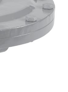
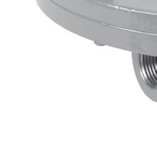

1 MR98 Series Backpressure Regulators, Relief and Differential Relief Valves January 2014 P1753 TyPE MR98H P1757 TyPE MR98L Figure 1. Typical MR98 Series Backpressure Regulators, Relief and Differential Relief Valves D103743X012
2 Specifications This section lists the specifications for the MR98 Series regulators. Factory specification such as type, maximum inlet pressure, maximum temperature, maximum outlet pressure, spring range, orifice size and seat material are stamped on the nameplate fastened on the regulator at the factory. Available Constructions Type MR98L: Direct-operated low pressure backpressure regulator/relief valve with 2 to 38 psig / 0.14 to 2.6 bar set pressure range Type MR98H: Direct-operated high pressure backpressure regulator/relief valve with 5 to 200 psig / 0.34 to 13.8 bar set pressure range Type MR98HH: Direct-operated high pressure backpressure/relief valve with psig / bar set pressure range Type MR98LD: Pressure-loaded low pressure differential pressure relief valve with 2 to 38 psi / 0.14 to 2.6 bar set pressure range Type MR98HD: Pressure-loaded high pressure differential pressure relief valve with 5 to 200 psi / 0.34 to 13.8 bar set pressure range Type MR98HHD: Pressure-loaded high pressure backpressure/relief valve with psi / bar differential set pressure range Body Sizes and End Connection Styles See Tables 1 and 2 Main Valve Materials See Table 5 Trim Materials See Tables 4 and 5 Body and Orifice Sizes body: inch / 7.22 mm 1/2-inch / DN 15 body: inch / mm 3/4 and 1-inch / DN bodies: inch / mm 1-1/2 and 2-inch / DN 40 and 50 bodies: inches / 29 mm Maximum Cold Working Pressures of Body Size and Material (1)(3) See Table 6 Maximum Inlet and Outlet Pressure Ratings (1)(4) See Table 6 Relief Pressure Ranges (1) See Table 3 Maximum Spring Case Loading Pressure for Types MR98LD, MR98HD and MR98HHD (Spring Setting Plus Loading Pressure) (1)(2) Type MR98LD Spring Case Gray Cast Iron: 50 psig / 3.4 bar Steel or Stainless steel: 125 psig / 8.6 bar Type MR98HD Spring Case Gray Cast Iron: 250 psig / 17.2 bar Steel or Stainless steel: psig / bar Type MR98HHD Spring Case Steel or Stainless steel: psig / bar Temperature Capabilities for Elastomer Parts (1)(5) MATERIAL TEMPERATURE RANGE Nitrile (NBR) -40 to 180 F / -40 to 82 C Neoprene (CR) -40 to 180 F / -40 to 82 C Fluorocarbon (FKM) (6) 0 to F / -18 to 149 C Limited to 200 F / 93 C for hot water Ethylenepropylene (EPDM) (6) 20 to 275 F / -7 to 135 C Perfluoroelastomer (FFKM) (6) 0 to 425 F / -18 to 218 C Polytetrafluoroethylene (PTFE) Diaphragm Protector -40 to 400 F / -40 to 204 C Temperature Capabilities of Body Materials (1)(5) MATERIAL TEMPERATURE RANGE Gray Cast Iron -20 to 406 F / -29 to 208 C LCC Steel -40 to 450 F / -40 to 232 C WCC Steel -20 to 450 F / -29 to 232 C Stainless steel, Monel or Hastelloy C Flow Coefficients -40 to 450 F / -40 to 232 C Body size Inch Dn C v C g C / /4 and /2 and 2 40 and The pressure/temperature limits in this Bulletin and any applicable standard limitation should not be exceeded. 2. Loading pressure plus spring setting should not exceed maximum inlet pressure. 3. Temperature and/or the body end connection may decrease these maximum pressures. 4. Maximum inlet pressure equals set pressure plus build-up. 5. Pressure and/or the body end connection may decrease these maximum temperatures. 6. Not for use on steam service. Hastelloy C is a mark owned by Haynes International, Inc. Monel is a mark owned by Special Metals Corporation. 2
3 Specifications (continued) IEC Sizing Coefficients Body size Inch Dn X t F d f l K m / /4 and /2 and 2 40 and Flow Capacities Types MR98L and MR98LD: See Tables 7 through 11 Types MR98H and MR98HD: See Tables 12 through 16 Types MR98HH and MR98HHD: See Tables 17 through 21 Shutoff Classification Per ANSI/FCI Metal Seats: Class IV Polytetrafluoroethylene (PTFE): Class IV Elastomer Seats: Class VI or better Pressure Registration Internal or External Approximate Weights MR98H Series: body: 5 pounds / 2.3 kg 1/2-inch / DN 15 body: 10 pounds / 4.5 kg 3/4 and 1-inch / DN bodies: 22 pounds / 10 kg 1-1/2 and 2-inch / DN 40 and 50 bodies: 55 pounds / 25 kg MR98L Series: body: 7 pounds / 3.2 kg 1/2-inch / DN 15 body: 15 pounds / 6.8 kg 3/4 and 1-inch / DN bodies: 35 pounds / 16 kg Options Handwheel or tee handle for Types MR98L, MR98H and MR98HH Tapped spring case vent for Types MR98L, MR98H and MR98HH Seal washer to permit spring case pressure loading for Types MR98L, MR98H and MR98HH Introduction MR98 Series (Figure 1) is used for backpressure or relief applications in liquid, gas, air and steam service. The Types MR98L, MR98H and MR98HH are direct-operated and spring-loaded. The Types MR98LD, MR98HD and MR98HHD use additional pressure loading to maintain relief differential pressures, backpressures or for remote setpoint adjustment. Features Versatility Typical applications include control and maintenance of backpressure on pumps, differential pressure across lubricated seals, steam header pressure, fuel and oil lines pressure, air supply systems pressure, pump bypass applications for API general and special purpose lube and seal oil systems, relief applications for flash tanks and accumulators and other process and industrial uses. Excellent Fluid Compatibility Diaphragms come in stainless steel, Monel, Hastelloy C or elastomers and body is available in gray cast iron, steel, stainless steel, Aluminum-bronze, Hastelloy C and Monel. Corrosion-resistant trims are available. Hastelloy C is a mark owned by Haynes International, Inc. Monel is a mark owned by Special Metals Corporation. Close, Stable Regulation Diaphragm is isolated from the main flow stream. Slotted valve plug and pusher post assembly provides positive guiding for improved shutoff. Compact Design Small size allows easy installation in limited spaces. Differential Pressure Capability Spring-loaded PTFE packing and tapped connections permit pressure loading of Types MR98LD, MR98HD and MR98HHD spring cases. Handwheels Handwheels (standard on the Types MR98LD, MR98HD and MR98HHD and optional on some sizes of the Types MR98L and MR98H) allow easy pressure setting changes. Sour Gas Service Capability Optional materials are available for applications handling sour gases. These constructions comply with the recommendations of NACE International Standards MR and MR0103. Optional materials are available to meet ANSI/NACE MR0175/ISO 15156, please contact your local Sales Office for special ordering instructions. Customers have the responsibility to specify correct materials. Environmental limitations may apply and shall be determined by the user. 3
4 Table 1. Types MR98L and MR98LD Regulators Body Constructions Body Material Body Size BODY CONSTRUCTION End Connection Style Gray Cast Iron WCC or LCC Steel CF8M Stainless Steel (1) CF3M Stainless Steel (1) Monel or Hastelloy C (1) 1/4-inch Without Control Line and Gauge Port SWE 1/2-inch / DN 15 Without Control Line and Gauge Port Welded CL150 RF Welded CL RF Welded PN 16/25/40 RF With Control Line but Without Gauge Port SWE Without Control Line and Gauge Port Welded CL150 RF Welded CL RF 3/4-inch / DN 20 With Control Line but Without Gauge Port Welded PN 16/25/40 RF With Gauge Port but Without Control Line Welded CL150 RF Welded CL RF Welded PN 16/25/40 RF SWE Without Control Line and Gauge Port Welded CL150 RF Welded CL RF 1-inch / DN 25 With Control Line but Without Gauge Port Welded PN 16/25/40 RF With Gauge Port but Without Control Line Welded CL150 RF Welded CL RF Welded PN 16/25/40 RF - Shaded areas indicate that the construction is available. - Blank areas indicate that you need to contact your local Sales Office for the availability of the constructions. 1. Meets the chemical and physical requirements of NACE MR and NACE MR0103. Monel is a mark owned by Special Metals Corporation. Hastelloy C is a mark owned by Haynes International, Inc. 4
5 Table 2. Types MR98H, MR98HD, MR98HH and MR98HHD Regulators Body Constructions Body Material Body Size BODY Constructions End Connection STYLE Gray Cast Iron (2) WCC or LCC Steel CF8M Stainless Steel (1) CF3M Stainless Steel (1) Monel or Hastelloy C (1) Aluminum-Bronze 1/4-inch Without Control Line and Gauge Port SWE Welded CL150 RF Without Control Line and Gauge Port Welded CL RF Welded PN 16/25/40 RF 1/2-inch / DN 15 Integral CL150 RF Integral CL RF Integral PN 16/25/40 RF With Control Line but Without Gauge Port Welded CL150 RF Welded CL RF SWE Without Control Line and Gauge Port Welded CL150 RF Welded CL RF Welded PN 16/25/40 RF 3/4-inch / DN 20 With Control Line but Without Gauge Port Welded CL150 RF Welded CL RF With Gauge Port but Without Control Line Welded CL150 RF Welded CL RF Welded PN 16/25/40 RF SWE Welded CL150 RF Without Control Line and Gauge Port Welded CL RF Welded PN 16/25/40 RF Integral CL150 RF Integral CL RF 1-inch / DN 25 Integral PN 16/25/40 RF With Control Line but Without Gauge Port Welded CL150 RF Welded CL RF With Gauge Port but Without Control Line Welded CL150 RF Welded CL RF Welded PN 16/25/40 RF - Shaded areas indicate that the construction is available. - Blank areas indicate that you need to contact your local Sales Office for the availability of the constructions. 1. Meets the chemical and physical requirements of NACE MR and NACE MR Available for Types MR98H and MR98HD only. - continued - Monel is a mark owned by Special Metals Corporation. Hastelloy C is a mark owned by Haynes International, Inc. 5
6 Table 2. Types MR98H, MR98HD, MR98HH and MR98HHD Regulators Body Constructions (continued) Body Material Body Size BODY Constructions End Connection STYLE Gray Cast Iron WCC or LCC Steel CF8M Stainless Steel (1) CF3M Stainless Steel (1) Monel or Hastelloy C (1) Aluminum-Bronze SWE Without Control Line and Gauge Port Welded CL150 RF Welded CL RF Welded PN 16/25/40 RF 1-1/2-inch / DN 40 Types MR98H and MR98HD only With Control Line but Without Gauge Port Welded CL150 RF Welded CL RF With Gauge Port but Without Control Line Welded CL150 RF Welded CL RF Welded PN 16/25/40 RF SWE Welded CL150 RF Without Control Line and Gauge Port Welded CL RF Welded PN 16/25/40 RF Integral CL150 RF 2-inch / DN 50 Types MR98H and MR98HD only Integral CL RF Integral PN 16/25/40 RF With Control Line but Without Gauge Port Welded CL150 RF Welded CL RF With Gauge Port but Without Control Line Welded CL150 RF Welded CL RF Welded PN 16/25/40 RF - Shaded areas indicate that the construction is available. - Blank areas indicate that you need to contact your local Sales Office for the availability of the constructions. 1. Meets the chemical and physical requirements of NACE MR and NACE MR0103. Monel is a mark owned by Special Metals Corporation. Hastelloy C is a mark owned by Haynes International, Inc. 6
7 Table 3. MR98 Series Body Sizes, Pressure Ranges and Spring Information TYPE MR98L and MR98LD MR98H and MR98HD MR98HH and MR98HHD BODY SIZE CONTROL RANGE (1) SPRING WIRE DIAMETER SPRING FREE LENGTH Inch DN psig bar Inch mm Inch mm 1/ /2 15 3/4 and 1 3/4 and 1 20 and and 25 1/ /2 15 3/4 and 1 3/4 and 1 1-1/2 and 2 20 and and and 50 SPRING MATERIAL SPRING PART NUMBER SPRING COLOR 2 to to Zinc-plated steel 1E Yellow 6 to to Zinc-plated steel ERAA01888A0 Green 12 to to Powder-coated steel ERAA01889A0 Red 20 to to Powder-coated steel ERAA01929A0 Blue 2 to to Powder-coated steel ERCA04288A0 Yellow 6 to to Powder-coated steel ERAA01910A0 Green 12 to to Powder-coated steel ERAA01911A0 Red 20 to to Powder-coated steel ERAA02889A0 Blue 2 to to Powder-coated steel 1E Yellow 6 to to Powder-coated steel 1E Green 12 to to Powder-coated steel 1E Red 20 to to Powder-coated steel 1L Blue 2 to to Powder-coated Stainless steel 1E3989X0052 Yellow 6 to to Stainless steel 1K Unpainted 12 to to Stainless steel 11A8269X012 Unpainted 15 to to Zinc-plated steel 1E Yellow 25 to to Zinc-plated steel ERAA01888A0 Green 70 to to Powder-coated steel ERAA01889A0 Red 130 to to Powder-coated steel ERAA01929A0 Blue 15 to to Powder-coated steel ERCA04288A0 Yellow 25 to to Powder-coated steel ERAA01910A0 Green 70 to to Powder-coated steel ERAA01911A0 Red 130 to to Powder-coated steel ERAA02889A0 Blue 15 to to Powder-coated steel 1E Yellow 25 to to Powder-coated steel 1E Green 70 to to Powder-coated steel 1E Red 130 to to Powder-coated steel 1L Blue 15 to to Powder-coated Stainless steel 1E3989X0052 Yellow 25 to to Stainless steel 1K Unpainted 70 to to Stainless steel 11A8269X012 Unpainted 5 to to Powder-coated steel 1E Dark Gray 20 to to Powder-coated steel ERCA04290A0 Black with light blue stripe 50 to to Powder-coated steel ERAA01893A0 Light Gray 75 to to Powder-coated steel 1P7888X0022 Black 1/ Powder-coated steel 1N Unpainted 1/ Powder-coated steel 1N Unpainted 3/4 and 1 20 and Zinc-plated steel 1N Unpainted 1. All springs may be backed off to 0 psig / 0 bar. However, highest capacities and best performances are obtained by using these springs in their recommended ranges. 7
8 Adjusting screw Control spring Vent Diaphragm Valve plug Orifice CONTROL LINE TAP ERSA02737 TYPE MR98H WITH INTERNAL REGISTRATION INLET OUTLET ATMOSPHERIC BACK VIEW OF 1/2 INCH / DN 15 TYPE MR98H WITH EXTERNAL REGISTRATION SIDE AND INTERNAL VIEW OF 3/4 TO 2-INCH / DN 20 TO 50 TYPE MR98H WITH EXTERNAL REGISTRATION (ALSO TYPICAL OF TYPE MR98L, 1/2 TO 2-INCH / DN 15 TO 50 BODIES) TYPE T208 WITH INTERNAL REGISTRATION Metal diaphragms Spring Metal diaphragm Spring Gasket Gasket For type MR98H with two metal diaphragms (Also typical of types MR98HH and MR98L except for Type MR98l, BODY, 2 to 7 psi / 0.1 TO 0.48 bar range) Type MR98L ( BODY, 2 to 7 psi / 0.14 TO 0.48 bar range) With one metal diaphragm Figure 2. MR98 Series Operational Schematics Principle of Operation Relief or backpressure valves respond to changes in upstream pressure. Pressure changes register under the diaphragm (see Figure 2) through a registration hole in the valve body or through an external control line. When the pressure increases beyond the spring setting, ERSA02738 the diaphragm pressure overcomes the spring compression. INLET This causes the valve plug to move OUTLET ATMOSPHERIC away from the orifice. The flow path through the valve is open and excess pressure is vented. When upstream pressure drops below setpoint, the valve resumes its closed position. Differential relief valves are used to maintain a differential pressure between the controlled pressure and loading pressure of a system. The spring setting determines the differential. 8 TYPE T208M WITH EXTERNAL REGISTRATION
9 Handwheel Control spring Loading pressure inlet tap Diaphragm Valve plug ORIFICE CONTROL LINE TAP INLET OUTLET LOADING TYPE MR98HD WITH INTERNAL REGISTRATION TYPE MR98HD WITH EXTERNAL REGISTRATION Spring Metal diaphragms GASKET Figure 2. MR98 Series Operational Schematics (continued) For types MR98HD, MR98HHD and MR98LD with metal diaphragms, assemble diaphragm gaskets under and above the metal diaphragms as shown above The differential relief valve responds to both controlled pressure and loading pressure and opens or closes as these pressures change. If the loading pressure increases, pressure on the upper side of the diaphragm increases. The valve plug moves closer to the orifice and restricts the flow through the relief valve. When loading pressure decreases, pressure on the upper side of the diaphragm decreases. This allows the valve plug to move away from the orifice and allow more flow through the differential relief valve (to atmosphere or back into the system). The differential relief valve opens and closes in response to changes in the controlled pressure. In this way, the differential pressure between the controlled and outlet pressures is maintained. Capacity Information Relieving capacities at selected pressures and outlet pressure flows are given in SCFH (60 F and 14.7 psia) of air in Tables 10, 11, 15, 16, 20 and 21. To determine the equivalent capacities for other gases, multiply the table capacities by the following appropriate conversion factors: 1.29 for 0.6 specific gravity natural gas, for propane, for butane or for nitrogen. For gases of other specific gravities, divide by the square root of the appropriate specific gravity. Then, if capacity is desired in normal cubic meters per hour (Nm 3 /h) at 0 C and bar, multiply SFCH by
10 Typical relieving capacities in pounds per hour and kilogram per hour of saturated steam are shown in Tables 9, 14 and 19. Tables 7, 8, 12, 13, 17 and 18 give relieving capacities in U.S. gallons per minute and in liters per minute of water. Sizing Determine Flow Rates for units used as differential relief valves as follows: Air and Steam Service When the Capacity Information section do not cover the actual service conditions, it will be necessary to calculate the flow rate available from the relief valve. Step 1. From the Capacity Information section determine a flow rate using the closest available data for setpoint and build-up. With this information, calculate a flow coefficient using the following: Equation 1: C g = 520 GT P 1a SIN Q 3417 ) C 1 P P 1a ) DEG C g = Calculated flow coefficient Q = Flow rate from tables (SCFH) P 1a = Inlet pressure from table (set pressure and build-up) converted to absolute pressure G = Specific gravity T = Absolute temperature of gas at inlet, Rankine = F P 1 = Absolute inlet pressure, psia = psig C 1 = See specifications section P = P 1 - P 2, psid Calculate the C g coefficient for the setting and build-up nearest to the desired service conditions within the selected spring range. Then use this C g to calculate the approximate flow available for the actual setpoint and build-up desired. Available C g will vary based upon setpoint, differential pressure, build-up and spring range. Step 2. Calculate the actual flow rate available using the coefficient from Step 1 and the actual inlet pressure (setpoint plus build-up) and actual outlet pressure (if not atmospheric). Equation 2: ) P Q SCFH = C g P 1a SIN DEG GT C 1 P 1a Liquid Sizing for Liquids Other than Water Step 1. Determine C v at build-up conditions of application. Q P C v C v = ) Q P = Flow in gpm from capacity tables = Pressure drop in psi (setpoint and build-up) = Valve sizing coefficient Step 2. To determine flow rate for liquids other than water or flow rate for differential relief service: Q = C v P/G G = Specific gravity of fluid Maximum Allowable Pressure Drop for Liquid Service Pressure drops in excess of allowable will result in choked flow and possible cavitation damage. To determine maximum allowable pressure drop for water: P(allow) = K m (P 1 ) P = Valve differential - psi K m = Valve recovery coefficient from table P 1 = Valve inlet pressure psig To determine maximum allowable pressure drop for fluids other than water, see Fisher Sizing Program. Installation These valves may be installed in any position, as long as flow will be in the same direction as that of the arrow cast on the body. For dimensional information see Figure 4. Emerson Process Management Regulator Technologies, Inc. (Regulator Technologies), provides an instruction manual with every valves shipped. Refer to this for complete installation, operation and maintenance instructions. Included is a complete listing of individual parts and recommended spare parts. 10
11 Table 4. MR98 Series Trim Materials Trim number Seat Orifice/ valve plug Valve plug guide Stem/stem guide Bottom plug Washer Stainless Steel 416 Stainless Steel 416 Stainless Steel 416 Stainless Steel 416 Stainless Steel 302 Stainless Steel Stainless Steel 316 Stainless Steel 316 Stainless Steel 316 Stainless Steel 316 Stainless Steel 316 Stainless Steel 3 Alloy 6 (1) Alloy 6 (1) 316 Stainless Steel 316 Stainless Steel 316 Stainless Steel 316 Stainless Steel 4 Hastelloy C Hastelloy C Hastelloy C Hastelloy C Hastelloy C Hastelloy C 5 Monel Monel Monel Monel Monel Monel 6 Nitrile (NBR) 416 Stainless Steel 416 Stainless Steel 416 Stainless Steel 416 Stainless Steel 302 Stainless Steel 7 Nitrile (NBR) 316 Stainless Steel 316 Stainless Steel 316 Stainless Steel 316 Stainless Steel 316 Stainless Steel 8 Fluorocarbon (FKM) 416 Stainless Steel 416 Stainless Steel 416 Stainless Steel 416 Stainless Steel 302 Stainless Steel 9 Fluorocarbon (FKM) 316 Stainless Steel 316 Stainless Steel 316 Stainless Steel 316 Stainless Steel 316 Stainless Steel 10 Ethylenepropylene (EPDM) 416 Stainless Steel 416 Stainless Steel 416 Stainless Steel 416 Stainless Steel 302 Stainless Steel 11 Ethylenepropylene (EPDM) 316 Stainless Steel 316 Stainless Steel 316 Stainless Steel 316 Stainless Steel 316 Stainless Steel 1. Alloy 6 is not available for 1/4-inch size. Table 5. MR98 Series Construction Materials main valve materials Body Spring Case Control Spring Gray cast iron, WCC/LCC steel, CF8M/CF3M stainless steel, Monel, Hastelloy C or Aluminum-Bronze Gray cast iron, WCC/LCC steel, CF8M stainless steel, Monel or Hastelloy C Zinc-plated steel, Stainless steel, Powder-coated steel or Powder-coated stainless steel trim materials Part Name Standard Optional Elastomer Seat Seat Nitrile (NBR) Fluorocarbon (FKM), EPDM or Perfluoroelastomer (FFKM) Diaphragm Neoprene (CR) 302 Stainless steel (1), Fluorocarbon (FKM) (2), Ethylenepropylene (EPDM) (2), Monel (1), Hastelloy C (1) or with PTFE protector (3) Orifice 416 Stainless steel 316 Stainless steel, Monel or Hastelloy C Valve Plug 416 Stainless steel 316 Stainless steel, Monel or Hastelloy C Valve Plug Guide 416 Stainless steel 316 Stainless steel, Monel or Hastelloy C Pusher Post 416 Stainless steel 316 Stainless steel, Monel or Hastelloy C Washer 302 Stainless steel 316 Stainless steel, Monel or Hastelloy C Metal Seat Seat 416 Stainless steel 316 Stainless steel, Monel, Hastelloy C or Alloy 6 Diaphragm 302 Stainless steel (1) Ethylenepropylene (EPDM) (2), Neoperene (CR) or Monel (1), Hastelloy C (1), Fluorocarbon (FKM) (2), with PTFE protector (3) Orifice 416 Stainless steel 316 Stainless steel, Monel, Hastelloy C or Alloy 6 Valve Plug 416 Stainless steel 316 Stainless steel, Monel, Hastelloy C or Alloy 6 Valve Plug Guide 416 Stainless steel 316 Stainless steel, Monel or Hastelloy C Pusher Post 416 Stainless steel 316 Stainless steel, Monel or Hastelloy C Washer 302 Stainless steel 316 Stainless steel, Monel or Hastelloy C 1. Two diaphragms are required if metal diaphragm is to be used except for Types MR98L and MR98LD, 2 to 7 psi / 0.1 to 0.5 bar which use only one. 2. Two diaphragms are required if Fluorocarbon (FKM) or Ethylenepropylene (EPDM) diaphragm is to be used. 3. PTFE protector is only available for Fluorocarbon (FKM), Neoprene (CR) or 302 Stainless steel diaphragm. Monel is a mark owned by Special Metals Corporation. Hastelloy C is a mark owned by Haynes International, Inc. 11
12 Table 6. Maximum Cold Working Pressures of Body Size and Materials (1)(2) REGULATOR Type MR98L MR98LD MR98H MR98HD MR98HH MR98HHD BODY SIZE All Sizes All Sizes All Sizes All Sizes All Sizes All Sizes BODY AND SPRING CASE MATERIALS Gray Cast Iron Steel Stainless Steel Monel Hastelloy C Gray Cast Iron Steel Stainless Steel Monel Hastelloy C Gray Cast Iron Steel Stainless Steel Monel Hastelloy C Aluminum-Bronze Gray Cast Iron Steel Stainless Steel Monel Hastelloy C Aluminum-Bronze Steel Stainless Steel Monel Hastelloy C Aluminum-Bronze Steel Stainless Steel Monel Hastelloy C Aluminum-Bronze MAXIMUM Spring case MAXIMUM INLET (3) MAXIMUM outlet psig bar psig bar psig bar The pressure/temperature limits in this Bulletin and any applicable standard limitation should not be exceeded. 2. Temperature, trim material, and/or the body end connection may decrease these maximum pressures. 3. Maximum inlet pressure equals set pressure plus build-up Table 7. Water Relief Capacities in Gallons per Minute / L/min, Types MR98L and MR98LD with Elastomer Diaphragm BODY SIZE, RELIEF COLOR RANGES CODE 2 / / / / / 0.69 psi bar psig bar GPM l/min GPM l/min GPM l/min GPM l/min GPM l/min to to 0.97 Green to to 0.97 Green to to 0.97 Green continued - Monel is a mark owned by Special Metals Corporation. Hastelloy C is a mark owned by Haynes International, Inc. 12
13 Table 7. Water Relief Capacities in Gallons per Minute / L/min, Types MR98L and MR98LD with Elastomer Diaphragm (continued) BODY SIZE, SPRING RELIEF RELIEF RANGES COLOR 15 / / / / 2.1 CODE psi bar psig bar GPM l/min GPM l/min GPM l/min GPM l/min to to 0.97 Green to to 0.97 Green to to 0.97 Green Universal NACE Compliance Optional materials are available for applications handling sour gases. These constructions comply with the recommendations of NACE International sour service standards. The manufacturing processes and materials used by Regulator Technologies assure that all products specified for sour gas service comply with the chemical, physical and metallurgical requirements of NACE MR and/or NACE MR0103. Optional materials are available to meet ANSI/NACE MR0175/ISO 15156, please contact your local Sales Office for special ordering instructions. Customers have the responsibility to specify correct materials. Environmental limitations may apply and shall be determined by the user. 13
14 Table 8. Water Relief Capacities in Gallons per Minute / L/min, Types MR98L and MR98LD with Metal Diaphragm BODY SIZE, SPRING RELIEF RANGES COLOR CODE RELIEF 2 / / / / / 0.69 psi bar psig bar GPM l/min GPM l/min GPM l/min GPM l/min GPM l/min to to 0.97 Green to to 0.97 Green to to 0.97 Green continued - 14
15 Table 8. Water Relief Capacities in Gallons per Minute / L/min, Types MR98L and MR98LD with Metal Diaphragm (continued) BODY SIZE, SPRING RELIEF RANGES COLOR CODE RELIEF 15 / / / / 2.1 psi bar psig bar GPM l/min GPM l/min GPM l/min GPM l/min to to 0.97 Green to to 0.97 Green to to 0.97 Green
16 Table 9. Steam Relief Capacities in Pounds per Hour / kg/h, Types MR98L and MR98LD with Metal Diaphragm Only BODY SIZE, RANGES COLOR CODE RELIEF 2 / / / / / 0.69 psi bar psig bar lbs/h kg/h lbs/h kg/h lbs/h kg/h lbs/h kg/h lbs/h kg/h to to 0.97 Green to to 0.97 Green to to 0.97 Green continued - 16
17 Table 9. Steam Relief Capacities in Pounds per Hour / kg/h, Types MR98L and MR98LD with Metal Diaphragm Only (continued) BODY SIZE, RANGES COLOR CODE RELIEF 15 / / / / 2.1 psi bar psig bar lbs/h kg/h lbs/h kg/h lbs/h kg/h lbs/h kg/h to to 0.97 Green to to 0.97 Green to to 0.97 Green
18 Table 10. Air Relief Capacities in Scfh / Nm 3 /h, Types MR98L and MR98LD with Elastomer Diaphragm BODY SIZE, RANGES COLOR CODE RELIEF 2 / / / / / 0.69 psi bar psig bar scfh Nm 3 /h scfh Nm 3 /h scfh Nm 3 /h scfh Nm 3 /h scfh Nm 3 /h to to 0.97 Green to to 0.97 Green to to 0.97 Green , , , , , , , , continued - 18
19 Table 10. Air Relief Capacities in Scfh / Nm 3 /h, Types MR98L and MR98LD with Elastomer Diaphragm (continued) BODY SIZE, RANGES COLOR CODE RELIEF 15 / / / / 2.1 psi bar psig bar scfh Nm 3 /h scfh Nm 3 /h scfh Nm 3 /h scfh Nm 3 /h to to 0.97 Green to to 0.97 Green , , , to to 0.97 Green , , , , , , , , , , , , , , , , , , , , , , , , , , ,
20 Table 11. Air Relief Capacities in Scfh / Nm 3 /h, Types MR98L and MR98LD with Metal Diaphragm BODY SIZE, SPRING RELIEF RANGES COLOR CODE RELIEF 2 / / / / / 0.69 psi bar psig bar scfh Nm 3 /h scfh Nm 3 /h scfh Nm 3 /h scfh Nm 3 /h scfh Nm 3 /h to to 0.97 Green to to 0.97 Green to to 0.97 Green continued - 20
21 Table 11. Air Relief Capacities in Scfh / Nm 3 /h, Types MR98L and MR98LD with Metal Diaphragm (continued) BODY SIZE, SPRING RELIEF RANGES COLOR CODE RELIEF 15 / / / / 2.1 psi bar psig bar scfh Nm 3 /h scfh Nm 3 /h scfh Nm 3 /h scfh Nm 3 /h to to 0.97 Green to to 0.97 Green , , , to to 0.97 Green , , , , , , , , , , , , , , , , , , , ,
22 Table 12. Water Relief Capacities in Gallons per Minute / L/min, Types MR98H and MR98HD with Elastomer Diaphragm BODY SIZE, /2 and 2 / 40 and 50 RANGES COLOR CODE RELIEF - continued - 5 / / / / / 1.4 psi bar psig bar GPM l/min GPM l/min GPM l/min GPM l/min GPM l/min 15 to to to to to to to to to to to to to to to to to to to to to to to to to to to to to to to to 11.7 Yellow Green Red Blue Yellow Green Red Blue Yellow Green Red Blue Dark gray Black with light blue stripe Light gray Black
23 Table 12. Water Relief Capacities in Gallons per Minute / L/min, Types MR98H and MR98HD with Elastomer Diaphragm (continued) BODY SIZE, 1-1/2 and 2 / 40 and 50 RANGES COLOR CODE RELIEF 30 / / / / 6.9 psi bar psig bar GPM l/min GPM l/min GPM l/min GPM l/min 15 to to to to to to to to to to to to to to to to to to to to to to to to to to to to to to to to 11.7 Yellow Green Red Blue Yellow Green Red Blue Yellow Green Red Blue Dark gray Black with light blue stripe Light gray Black
24 Table 13. Water Relief Capacities in Gallons per Minute / L/min, Types MR98H and MR98HD with Metal Diaphragm BODY SIZE, 1-1/2 and 2 / 40 and 50 RANGES COLOR CODE RELIEF 5 / / / / / 1.4 psi bar psig bar GPM l/min GPM l/min GPM l/min GPM l/min GPM l/min 130 to to 13.8 Blue 130 to to 13.8 Blue 130 to to 13.8 Blue 5 to to 2.4 Dark gray 20 to to 4.5 Black with light blue stripe 50 to to 6.9 Light gray 75 to to 11.7 Black continued - 24
T205 Series Tank Blanketing Regulators
 T205 Series Tank Blanketing Regulators Bulletin 74.1:T205 September 2013 Figure 1. Type T205 Tank Blanketing Regulator Contents Features...1 Introduction...2 Specifi cations...2 Principle of Operation...2
T205 Series Tank Blanketing Regulators
 Bulletin 74.1 D103747X012 T205 Series June 2018 T205 Series Tank Blanketing Regulators Figure 1. Type T205 Tank Blanketing Regulator Contents Features... 1 Introduction.... 1 Specifications... 2 Principle
type 630r relief Valve
 December 2011 type 630r relief Valve W1934 Figure 1. Type 630R Relief Valve Introduction The Type 630R is a general relief valve that is available in NPS 1 and 2 / DN 25 and 50 body sizes. It is frequently
627 Series Pressure Reducing Regulators
 627 Series Pressure Reducing Regulators Introduction The 627 Series direct-operated pressure reducing regulators (Figure 1) are for low and high-pressure systems. These regulators can be used with natural
Type MR108 Direct-Operated Backpressure Regulators
 July 2016 Type MR108 Direct-Operated Backpressure Regulators P1202_1 P1203_1 Type mr108 with low-pressure Actuator Type mr108 with high-pressure actuator Figure 1. Type MR108 Direct-Operated Backpressure
627 Series Pressure Reducing Regulators
 627 Series Pressure Reducing Regulators Introduction The 627 Series direct-operated reducing regulators (Figure 1) are for low and high systems. These regulators can be used with natural gas, air, or a
Type T205B Balanced Tank Blanketing Regulator
 April 2014 Type T205B Balanced Tank Blanketing Regulator Figure 1. Type T205B Balanced Tank Blanketing Regulator Contents Introduction...2 Specifications...2 Features...3 Principle of Operation...3 Installation...4
627 Series Pressure Reducing Regulators
 627 Series Pressure Reducing Regulators Introduction The 627 Series direct-operated pressure reducing regulators (Figure 1) are for low and high pressure systems. These regulators can be used with natural
Types 1808 and 1808A Pilot-Operated Relief Valves or Backpressure Regulators
 Bulletin 71.4 D0163X012 Type 1808 February 17 Types 1808 and 1808A Pilot-Operated Relief Valves or Backpressure Regulators Type 1808 Type 1808A Figure 1. Types 1808 and 1808A Pilot-Operated Relief Valves
Type MR108 Direct-Operated Backpressure Regulators
 August 2013 Type MR108 Direct-Operated Backpressure Regulators P1202 P1203 TYPE MR108 WITH LOW- ACTUATOR TYPE MR108 WITH HIGH- ACTUATOR Figure 1. Type MR108 Direct-Operated Backpressure Regulators Contents
Type 310A-32A Pressure Reducing Regulator
 Bulletin 71.2 D102066X012 Type 310A February 2017 Type 310A-32A Pressure Reducing Regulator Figure 1. Type 310A Regulator with Type 32A Pilot Introduction The Type 310A pilot-operated high-pressure regulator
Type SR8 Sanitary Backpressure Regulator
 Type SR8 Sanitary Backpressure Regulator September 2015 Sanitary Design Standards Superior Flow Performance and Accuracy Wide Control Range Diaphragm Cycle Life Highly Stable Large Turndown Ratio Tight
T205VB Series Tank Blanketing Vacuum Breakers
 February 2014 T205VB Series Tank Blanketing Vacuum Breakers Figure 1. Typical T205VB Series Vacuum Breaker Introduction The T205VB Series vacuum breakers (Figure 1) are used for precise control of small
Type HSR Pressure Reducing Regulator for Residential, Commercial or Industrial Applications
 Bulletin 71.1 D103087X012 Type HSR December 2017 Type HSR Pressure Reducing Regulator for Residential, Commercial or Industrial Applications High Capacity Compact Design P1524_1 High Capacity Internal
cs200 series commercial / Industrial pressure reducing regulators
 November 2013 cs200 series commercial / Industrial pressure reducing regulators P1188 Figure 1. Typical CS200 Series Pressure Reducing Regulator Features and Benefits Wide Range of Body Sizes and End Connections
Y610A, Y611A, and Y612A Series Vacuum Service Equipment and Relief Valves
 Y610A, Y611A, and Y612A Series Vacuum Service Equipment and Relief Valves July 2013 W1094_1 Figure 1. Type Y610A or Y610AP Vacuum Breaker Introduction The Y610A, Y611A, and Y612A Series devices (Figures
Type HSR Pressure Reducing Regulator for Residential, Commercial, or Industrial Applications
 March 2013 Type HSR Pressure Reducing Regulator for Residential, Commercial, or Industrial Applications High Capacity Compact Design High Capacity Internal Relief TYPE HSR ANGLE BODY Globe Bodies Angle
CP400 Series Commercial/Industrial Pressure Loaded Pressure Reducing Regulators
 CP400 Series Commercial/Industrial Pressure Loaded Pressure Reducing Regulators September 2014 P1182 typical type cp400 regulator P1522 P1410 Typical type CP403 Regulator WITH INTEGRAL TRUE-MONITOR PROTECTION
Fisher Mr95 and Mr98 Series regulators transition Management guide
 Transition Management Guide MR95/MR98 Series March 2015 Fisher Mr95 and Mr98 Series regulators transition Management guide P1753 typical Mr95H/Mr98H SerieS P1757 typical Mr95L/Mr98L SerieS Figure 1. Typical
Types 1808 and 1808A Pilot-Operated Relief Valves or Backpressure Regulators
 Instruction Manual Form 5116 Types 1808 and 1808A July 2010 Types 1808 and 1808A Pilot-Operated Relief Valves or Backpressure Regulators! Warning Failure to follow these instructions or to properly install
Types 98L and 98H Backpressure Regulators and Relief Valves
 Instruction Manual Form 70 Types 98 and 98H January 0 Types 98 and 98H Backpressure Regulators and Relief Valves W65 W66 TYPE 98H OR 98HM TYPE 98 Figure. Types 98 and 98H Backpressure Regulators and Relief
CS800 Series Commercial/Industrial Pressure Reducing Regulators
 Bulletin 71.1 D103140X012 CS800 Series April 2018 CS800 Series Commercial/Industrial Pressure Reducing Regulators P1235 P1234 Type CS800 REGULATOR Type CS800IQ with High Capacity Relief P1521 P1692 TYPe
Type 63EG-98HM Pilot-Operated Relief Valve or Backpressure Regulator
 Instruction Manual Form 5475 Type 63EG-98HM October 009 Type 63EG-98HM Pilot-Operated Relief Valve or Backpressure Regulator! WARNING Failure to follow these instructions or to properly install and maintain
Types 95LD and 95HD Differential Pressure Regulators
 Itruction Manual Form 1396 Types 95LD and 95HD November 2009 Types 95LD and 95HD Differential Pressure Regulators W1894-1 W6195 W1894-1 TYPE 95LD TYPE 95LD (FLANGED) Figure 1. 95 Series Differential Pressure
167D Series Switching Valves
 June 2011 167D Series Switching Valves P1185 P1184 167D TWO-WAY SWITCHING VALVE 167DA THREE-WAY SWITCHING VALVE Figure 1. 167D Series Switching Valves Introduction The 167D Series switching valves are
67 Series Pressure Regulators
 67 Series Pressure Regulators Fisher Controls November 1986 Bulletin The 67 Series small-volume regulators (figure 1) are typically used to provide constantly controlled reduced pressures to pneumatic
Applications. T98H Part Matrix. Specifications. Spring Range. Materials of Construction. T98H Regulator Rebuild Kits. marshbellofram.
 TH Back Regulator / Valve The TH monitors upstream pressure and opens to relieve excess pressure increases above setpoint. s a Back Regulator, the upstream pressure is monitored and released downstream
OBSOLETE DOCUMENT. 167D Series Switching Valves. Bulletin 71.7:167D. Introduction. Features
 167D Series Switching Valves P1185 Type 167D Two-way Switching Valve Figure 1. 167D Series Switching Valves Introduction The 167D Series switching valves are typically used to deliver constant reduced
Y690A Series Pressure Reducing Regulators
 Instruction Manual Form 5463 Y690A Series February 2009 Y690A Series Pressure Reducing Regulators! Warning Fisher regulators must be installed, operated, and maintained in accordance with federal, state,
Type 1290 Vapor Recovery Regulator
 Instruction Manual Form 5308 Type 1290 February 2012 Type 1290 Vapor Recovery Regulator! warning Failure to follow these instructions or to properly install and maintain this equipment could result in
Type 63EG Relief Valve or Backpressure Regulator
 Instruction Manual Form 5110 Types 63EG and 1098-63EGR July 2011 Type 63EG Relief Valve or Backpressure Regulator! WARNING Failure to follow these instructions or to properly install and maintain this
type 63Eg Relief Valve or Backpressure Regulator
 Instruction Manual Form 5110 Types 63EG and 1098-63EGR March 2016 type 63Eg Relief Valve or Backpressure Regulator! WARning Failure to follow these instructions or to properly install and maintain this
Type 1290 Vapor Recovery Regulator
 Instruction Manual Form 5308 Type 1290 November 2015 Type 1290 Vapor Recovery Regulator! WARNING Failure to follow these instructions or to properly install and maintain this equipment could result in
P627 High Flow Gas Regulator
 P627 High Flow Gas Regulator Wide of Flow Capacities Durable Powder Coated Exterior Installation Versatility NACE Construction Available The P627 is a spring loaded, direct-operated regulator for both
Type EZR Relief Valve or Backpressure Regulator
 Instruction Manual Form 5476 Type EZR Relief October 2015 Type EZR Relief Valve or Backpressure Regulator W7347 Figure 1. Type EZR Relief Valve or Backpressure Regulator Introduction Scope of the Manual
Built-in Slam-Shut Valve. Independent pneumatic control Accuracy class: ±5% Response time: 1 second. 1/2, 11/16, and 3/4-inch (13, 18, and 19 mm)
") RP Series Regulators Introduction The RP Series regulators are direct-operated with non-balanced trim. Normally they are fitted with a built-in filter. They are produced in the following versions: Types
RP Series Regulators Introduction The RP Series regulators are direct-operated with non-balanced trim. Normally they are fitted with a built-in filter. They are produced in the following versions: Types
P630 High Flow Gas Regulator
 High Flow Gas Regulator Stainless Steel Internals are Standard Steel Units comply with NACE MR0175 Durable Powder Coated Exterior Wide of Flow Capacities The is a spring loaded, direct-operated regulator
289 Series Relief Valves
 Instruction Manual Form 174 89 Series May 013 89 Series Relief Valves! WARNING Failure to follow these instructions or to properly install and maintain this equipment could result in an explosion and/or
Y690A Series Pressure Reducing Regulators
 Instruction Manual Form 5463 Y690A Series April 1999 Y690A Series Pressure Reducing Regulators Introduction Scope of Manual This manual provides instructions for installation, startup, maintenance, and
Type EZR Relief Valve or Backpressure Regulator
 Type EZR Relief Valve Backpressure Regulat 03/0 Internally Actuated Quiet Operation Exceptional Design Thoughly Tested Robust Construction W7393, 2, 3, 4 and 6-inch (DN 25, 50, 80, and 50) Body Sizes Patent
Types 1098-EgR and 1098H-EgR Pressure Reducing Regulators
 Instruction Manual Form 5084 October 2014 Types 1098-EGR and 1098H-EGR Types 1098-EgR and 1098H-EgR Pressure Reducing Regulators! warning Failure to follow these instructions or to properly install and
133 Series Direct-Operated Regulators
 Instruction Manual Form 5007 133 Series January 2016 133 Series Direct-Operated Regulators Table of Contents Introduction...1 Specifications...2 Principle of Operation...2 Installation...3 Overpressure
Type EZR Relief Valve or Backpressure Regulator
 Instruction Manual Form 5476 Type EZR Relief May 2012 Type EZR Relief Valve or Backpressure Regulator Introduction Scope of the Manual W7347 This instruction manual provides installation, startup, shutdown,
Type 99 Pressure Reducing Regulator
 Instruction Manual Form 589 Type 99 February 2016 Type 99 Pressure Reducing Regulator! WARNINg Since a pilot-operated regulator is constructed of both a pilot and a main valve, care should be used not
Type MR105 Direct-Operated Pressure Reducing Regulators
 Instruction Manual Form 5874 Type MR105 December 2014 Type MR105 Direct-Operated Pressure Reducing Regulators Contents Introduction...2 Specifications...2 Principle of Operation...3 Installation...4 Overpressure
P627 High Flow Gas Regulator
 P627 High Flow Gas Regulator Wide of Flow Capacities Durable Powder Coated Exterior Installation Versatility NACE Construction Available The P627 is a spring loaded, direct-operated regulator for both
Type LR128 Relief Valve or Backpressure Liquid Regulator
 Instruction Manual Type LR128 February 2013 Type LR128 Relief Valve or Backpressure Liquid Regulator TYPE LR128 REGULATOR TYPE 98HM PILOT Figure 1. Type LR128 Relief Valve or Backpressure Regulator and
P627 High Flow Gas Regulator
 P627 High Flow Gas Regulator Wide of Flow Capacities Durable Powder Coated Exterior Installation Versatility NACE Construction Available The P627 is a spring loaded, direct-operated regulator for both
R627 High Flow Gas Regulator with Internal Relief
 High Flow Gas Regulator with Internal Relief The Relieving Regulator has an internal relief valve that provides protection against over pressurization. As output pressure builds up above the start-to-discharge
Type 1190 Low-Pressure Gas Blanketing Regulator
 Instruction Manual Form 530 Type 90 June 20 Type 90 Low-Pressure Gas Blanketing Regulator! WARNING Failure to follow these instructions or to properly install and maintain this equipment could result in
Type EZH Relief or Backpressure Regulator
 Instruction Manual D10307X012 Type EZH Relief November 2017 Type EZH Relief or Backpressure Regulator Type PRX/12 Figure 1. Type EZH Regulator Figure 2. PRX Series Pilot! Warning Failure to follow these
Type 289P Pilot-Operated Relief Valve
 Instruction Manual D102680X012 Type 289P July 2017 Type 289P Pilot-Operated Relief Valve Figure 1. 1 NPT Type 289P Pilot-Operated Relief Valve Figure 2. 2 NPT Type 289P Pilot-Operated Relief Valve Introduction
Type MR108 Direct-Operated Backpressure Regulator
 Instruction Manual Form 5875 Type MR108 August 2013 Type MR108 Direct-Operated Backpressure Regulator Contents Introduction... 2 Specifi cations... 2 Principle of Operation... 6 Installation... 6 Overpressure
Type 289P Pilot-Operated Relief Valve
 Instruction Manual Form 5481 Type 289P February 2012 Type 289P Pilot-Operated Relief Valve W6834 W3167-2 Figure 1. 1 NPT Type 289P Pilot-Operated Relief Valve Figure 2. 2 NPT Type 289P Pilot-Operated Relief
Type 99 Pressure reducing regulator
 Instruction Manual Form 589 Type 99 March 2012 Type 99 Pressure reducing regulator W2676 Figure 1. Type 99 Regulator with Type 61H (High Pressure) Pilot introduction Scope of the Manual This manual describes
Type 92S Pilot-Operated Steam Regulators
 Instruction Manual Form 5234 Type 92S December 2011 Type 92S Pilot-Operated Steam Regulators! Warning Failure to follow these instructions or to properly install and maintain this equipment could result
P99 Pressure Reducing Regulator
 P99 Pressure Reducing Regulator Applications City / District gate operation Commercial buildings Boilers, furnace, oven Plant air service Features 5 Pilot choices for low to extra high pressure Up to 1,000
Model 5400 / 5450 Control Valve
 Model 5400 / 5450 Control Valve The Model 5400 (Figure ) and Model 5450 (Figure 2) control valves are designed to meet the high pressure and erosive applications common to the oil and gas industry. These
R627 High Flow Gas Regulator with Internal Relief
 High Flow Gas Regulator with Internal Relief The Relieving Regulator has an internal relief valve that provides protection against over pressurization. As output pressure builds up above the start-to-discharge
type 122a three-way Switching Valve
 Instruction Manual Form 2279 Type 122A January 2016 type 122a three-way Switching Valve! WarnIng Failure to follow these instructions or to properly install and maintain this equipment could result in
Application: Sanitary Solutions
 SANITARY Sanitary regulators are engineered for pressure control in sanitary, or clean environments. The applications include pharmaceutical, biotechnology, food and beverage, cosmetics, chemical and other
Design D4 Control Valve
 Product Bulletin Design D4 Control Valve D4 Valve The Design D4 control valve is a compact, rugged globe valve designed primarily for high-pressure throttling applications. This valve is ideal for use
Fisher D4 Control Valve Assembly
 Product Bulletin D103039X012 Fisher D4 Control Valve Assembly D4 Valve The Fisher D4 control valve is a compact, rugged globe valve designed primarily for high-pressure throttling applications. This valve
Vee-Ball Designs V150, V200 and V300 Rotary Control Valves
 January 000 Bulletin 5.3:Vee-Ball Vee-Ball Designs V50, V00 and V300 Rotary Control Valves This bulletin covers the - through -inch, 3- through -inch Series B, and the 4- through 0-inch Designs V50, V00
Fisher YD and YS Control Valves
 Product Bulletin D100031X012 Fisher YD and YS Control Valves Fisher YD (figure 1) and YS three-way cage-guided valves are designed for throttling or flow-switching (on-off) service, and are available in
Types 63EG and EGR
 Instruction Manual Form 5110 Types 63EG and 1098-63EGR July 2011! W6955 Figure 1. Type 63EG Relief Valve or Backpressure Regulator This instruction manual provides instructions for the installation, maintenance,
P200 Pressure Regulator
 P200 Pressure Regulator Minimize Sudden Downstream Load Change Wide Pressure Ranges P202 has internal relief valve for overpressure protection The P200 series pressure regulator is a manual, direct acting,
P200 Pressure Regulator
 P200 Pressure Regulator Minimize Sudden Downstream Load Change Wide Pressure Ranges P202 has internal relief valve for overpressure protection The P200 series pressure regulator is a manual, direct acting,
Baumann Series Sanitary Regulators
 Bulletin 84000 Series Regulators Baumann 84000 Series Sanitary Regulators Pressure regulation for your sanitary process. The Baumann 84000 series of sanitary regulators are designed specifically for those
T200 Pressure Regulator
 T200 Pressure Regulator Minimize Sudden Downstream Load Change Wide Pressure Ranges T202 has internal relief valve for overpressure protection The T200 series pressure regulator is a manual, direct acting,
Accessories. Section Outline
 Fisher Controls offers a line of accessories including filters, needle valves, pressure gauges, vent assemblies, and emergency shutoff valves. This section provides technical information for these accessories.
Type LR125 Pressure Reducing Liquid Regulator
 Instruction Manual Type LR125 September 2015 Type LR125 Pressure Reducing Liquid Regulator TYPE LR125 REGULATOR TYPE MR95H/MR95HP PILOT Figure 1. Type LR125 Pressure Reducing Liquid Regulator and Type
P95H Regulator Applications P95H Part Matrix Specifi cations Materials of Construction P95H Flow Coeffi cients Wide Open Coeffi cients
 PH Regulator Large Capacity Working Media Include ir, Steam and Liquids ll Vents are Tapped The PH is a direct operating pressure reducing regulator with large capacity. Ideally suited for uses in oil
P200 Pressure Regulator
 P200 Pressure Regulator Minimize Sudden Downstream Load Change Wide Pressure Ranges P202 has internal relief valve for overpressure protection The P200 series pressure regulator is a manual, direct acting,
119 Series Fuel Gas Valve
 Instruction Manual D100261X012 119 Series November 2016 119 Series Fuel Gas Valve Contents Introduction.... 4 Specifications... 2 Description..................................4 Principle of Operation....
Type EZR Pressure Reducing Regulator
 Instruction Manual D102600X012 Type EZR January 2018 Type EZR Pressure Reducing Regulator 161AY SERIES PILOT Type prx PILOT TYPE EZR REGULATOR Figure 1. Type EZR Pressure Reducing Regulator! Warning Failure
Vee-Ball Design V150, V200 and V300 Rotary Control Valves
 Product Bulletin Vee-Ball Design V150, V200 and V300 Rotary Control Valves Vee-Ball Valves This bulletin covers the 1- through 2-inch, 3- through 12-inch Series B, and the 14- through 20-inch Design V150,
Design V250 Rotary Control Valve
 Product Bulletin Design V250 Rotary Control Valve V250 Valve The Design V250 Hi-Ball rotary control valve (figure 1) is designed for heavy-duty throttling and on-off applications. Depending on size, this
Fisher eplug complete Rotary Control Valve and Actuator Package
 Product Bulletin D103196X012 eplug complete Fisher eplug complete Rotary Control Valve and Actuator Package...your complete control valve solution... simple...easy to select and install reliable...engineered
D I V I S I O N O F M A R S H B E L L O F R A M
 PH Regulator Large Capacity Working Media Include ir, Steam and Liquids ll Vents are Tapped The PH is a direct operating pressure reducing regulator with large capacity. Ideally suited for uses in oil
Fisher 8532 High-Performance Butterfly Valve
 8532 Valve Product Bulletin Fisher 8532 High-Performance Butterfly Valve The Fisher 8532 high-performance butterfly valve provides outstanding performance under extreme pressure and temperature conditions.
Model 5400 / 5450 Control Valve
 Model 5400 / 5450 Control Valve The Model 5400 (open yoke) and Model 5450 (closecoupled) control valves are designed to meet the high pressure and erosive applications common to the oil and gas industry.
Fisher HP Series Control Valves
 Product Bulletin D0635X0 Fisher HP Series Control s HP (Globe ) HPA (Angle ) Balanced High-Temperature Trim Balanced Tight Shutoff Trim Unbalanced Trim Fisher HP Series control valves (figure ) are single-port,
Fisher 8532 High-Performance Butterfly Valve
 8532 Valve Product Bulletin Fisher 8532 High-Performance Butterfly Valve The Fisher 8532 high-performance butterfly valve provides outstanding performance under extreme pressure and temperature conditions.
Type FL Pressure Reducing Regulators
 ulletin 71.2 D103067X012 Type FL January 2017 Type FL Pressure Reducing Regulators Features No tmospheric leed Eliminates nuisance and wasteful bleed gas to atmosphere by utilizing a self-contained control
Design D and DA Control Valves
 Product Bulletin Design D and DA Control Valves D and DA Valves Design D and DA single-port, high-pressure valves (figure ) are widely used in oil and gas production industries. These valves are especially
Type 8510 and 8510B Eccentric Disc Control Valves (EMA)
") Product Bulletin August 4 8510/8510B Valve Type 8510 and 8510B Eccentric Disc Control Valves (EMA) The Type 8510 and 8510B edisc valves feature an eccentrically mounted disc and a PTFE or 316 stainless
Product Bulletin August 4 8510/8510B Valve Type 8510 and 8510B Eccentric Disc Control Valves (EMA) The Type 8510 and 8510B edisc valves feature an eccentrically mounted disc and a PTFE or 316 stainless
Fisher 2100 Pneumatic and 2100E Electric Liquid Level Switches
 2100 and 2100E Level Switches Product Bulletin Fisher 2100 Pneumatic and 2100E Electric Liquid Level Switches Fisher 2100 on-off pneumatic switch and 2100E electric switch sense (shown in figure 1) high
Fisher V250 Rotary Control Valve
 V250 Valve Product Bulletin Fisher V250 Rotary Control Valve The V250 Hi Ball rotary control valve is designed for heavy duty throttling and on off applications. Depending on size, this valve installs
Fisher CV500 Rotary Globe Control Valve
 CV500 Valve D101606012 Product Bulletin Fisher CV500 Rotary Globe Control Valve The Fisher CV500 Cam Vee-Ball control valve combines the rangeability of the cammed-segmented V-notched ball, with the inherent
Fisher YD and YS Control Valves
 YD and YS Valves Product Bulletin Fisher YD and YS Control Valves Fisher YD and YS three-way cage-guided valves are designed for throttling or flow-switching (on-off) service, and are available in the
Fisher 8510 and 8510B Eccentric Disc Control Valves (EMA)
") Product Bulletin D100066X012 February 7 Fisher 8510 and 8510B Eccentric Disc Control Valves (EMA) 8510/8510B Valve Fisher 8510 and 8510B eccentric disc valves feature an eccentrically mounted disc and
Product Bulletin D100066X012 February 7 Fisher 8510 and 8510B Eccentric Disc Control Valves (EMA) 8510/8510B Valve Fisher 8510 and 8510B eccentric disc valves feature an eccentrically mounted disc and
Fisher V500 Rotary Globe Control Valve
 V500 Valve D100054012 Product Bulletin Fisher V500 Rotary Globe Control Valve The Fisher V500 eccentric plug rotary control valve controls erosive, coking, and other hard-to-handle fluids, providing either
Series Low Pressure Steam Heating Boiler Safety Valves
 12-200 Series Low Pressure Steam Heating Boiler Safety Valves Section IV Heating Boilers Medium capacity safety valves protect ASME Section IV low pressure steam heating boilers. Cast bronze, full nozzle
Type D2 FloPro Control Valve
 Product Bulletin Type D2 FloPro Control Valve D2 FloPro Valve The Type D2 FloPro control valve (figure 1) is a compact, rugged valve designed for on-off control. This valve is ideal for use as a dump valve
167D Series Switching Valves
 Instruction Manual Form 5859 167D Series June 2011 167D Series Switching Valves P1185 P1184 TYPE 167D TWO-WAY SWITCHING VAVE TYPE 167DA THREE-WAY SWITCHING VAVE Figure 1. 167D Series Switching Valves!
Fisher CAV4 Control Valve
 Product Bulletin D10197X012 Fisher CAV Control Valve CAV Valve The Fisher CAV control valve (figure 1) with Cavitrol IV trim is designed specifically for liquid applications, such as boiler feedwater recirculation,
Fisher V260 Ball Control Valve
 Fisher V260 Ball Control Valve The Fisher V260 is a full-bore control valve designed from the ground up with features for optimized pressure, flow and process control. An integral drilled attenuator controls
OBSOLETE DOCUMENT. 95 Series Industrial Pressure Regulators. Bulletin 71.1:95.
 95 Series Industrial Pressure Regulators W5091 / IL W1894-1 / IL TYPE 95LD TYPE 95L W6195 / IL Figure 1. 95 Series Pressure Reducing Regulators TYPE 95LD (FLNGED) www.emersonprocess.com/regulators ulletin
Type EZL Relief Valve or Backpressure Regulator
 Instruction Manual D104251X012 Type EZL June 2017 Type EZL Relief Valve or Backpressure Regulator W8962 Figure 1. Type EZL Relief or Backpressure Regulator Introduction Scope of the Manual This manual