Series Maintenance Manual. Technical Manual 197T R2
|
|
|
- Donna Hunt
- 6 years ago
- Views:
Transcription


1 Series 2700 Maintenance Manual Technical Manual 197T R2


2 Flanged Female NPT Inlet Sanitary Inlet Threaded Table of Contents 1. Introduction Numbering System...3 Standard Bill of Materials...4 Accessories Disassembly of Valves Dismantling...5 Lifting Lever Assemblies Refacing & Lapping Body Refacing...7 Disc Relapping...7 Lapping Compounds & Procedures Assembly Setting & Testing Testing Procedure...8 Set Pressure Test...8 Seat Leakage Test...9 Backpressure Test...9 Final Notes...10 Appendix A Critical Seat & Disc Dimensions

3 1. Introduction Numbering System The chart below illustrates the Farris Series 2700 valve type numbering system. The type number is imprinted on the nameplate of every Farris Series 2700 valve and describes its construction and metallurgy. Valve types with numbers ending in SP are special valves. Example: 27DA23-120/SP. Contact the Farris Factory for assistance when replacement parts or maintenance are required on these valves. 27 D A 2 3 H M 2 0 /S4 Series Number Orifice Area 27 US Customary Units Sq. In. C D E F G Metric mm 2 C D Seat Special Construction Inlet Size 1 Outlet Size 1 Variations A C T Metal Seat Soft Seat Teflon Seat 1 1/2" 2 3/4" 3 1" 4 1-1/2" 3 1" 4 1-1/2" 5 2" 6 2-1/2" H High pressure variations of standard types B Balanced design 3 D Heat transfer fluid standard pressure E Heat transfer fluid high pressure Inlet Connections M MNPT F FNPT 1 Flanged-150RF 2 Flanged-300RF 3 Flanged-600RF 4 Flanged-900RF 5 Flanged-1500RF 6 Flanged-2500RF O Special Cap Special Construction Test Gag 2 Materials 2 Plain 4 Packed Lever 7 Open Lever 0 No Gag 1 Test Gag S4 Complete 316 St. St. N1 NACE Trim: Standard N4 NACE Trim: All St. St. M1 Monel Body & Disc M2 Monel Internals M4 Complete Monel H1 Hastelloy C Body & Disc E F G S Socket Weld T Sanitary W Welding Nipple H2 Hastelloy C Internals H4 Complete Hastelloy C 27DA23-M20 3/4 D PSIG SCFM AIR KE PSV Teflon is a registered trademark of the DuPont Company. Monel is a registered trademark of Inco Alloys International Inc. Hastelloy and Hastelloy C are registered trademarks of Haynes International Inc. Figure 1.1 Nameplate for 2700 Series

 Stainless Steel 17 Welding Nipple (Inlet) 316 St. St. 18 Welding Nipple (Outlet) Carbon Steel 19 Lap Joint Stub End (Inlet) 316 St.")
 Retainer Lockscrew Balanced Design 1 20 4 18 Built in conformance to ASME Code Section VIII, capacity")

4 Bill of Materials Item Part Name Standard Material 1 1 Body SA-351, Gr. CF8M St. St. or SA-479 Type 316 St. St. 2 Bonnet SA-216, Gr. WCB, Carb. St. 3 Disc 316 St. St. 4 Guide 316 St. St. 5 Disc Holder 316 St. St. 6 Stem 316 St. St. 7 Spring Adj. Screw 316 St. St. 8 Jam Nut 316 St. St. 9 Cap, Plain Screwed Carbon Steel 10 Cap Gasket 316 St. St. 11 Body Gasket 316 St. St. 12 Guide Gasket 316 St. St. 13 Spring (-20 F to +750 F) Chrome Alloy, Rust Proofed 14 Spring Buttons 316 St. St. 15 Wire Seal St. St. Wire / Lead Seal 16 Nameplate (Not Shown) Stainless Steel 17 Welding Nipple (Inlet) 316 St. St. 18 Welding Nipple (Outlet) Carbon Steel 19 Lap Joint Stub End (Inlet) 316 St. St. 20 Lap Joint Stub End (Outlet) Carbon Steel 21 Lap Joint Flange (Inlet) Carbon Steel 22 Lap Joint Flange (Outlet) Carbon Steel O-Ring Retainer O-Ring Design (Optional) Retainer Lockscrew Balanced Design Built in conformance to ASME Code Section VIII, capacity certified by National Board for air, gas, steam and liquid. Figure 1.2 Conventional Design General Notes: 1. See 2700 Series Catalog for alternate materials of construction Figure 1.3 Figure 1.4
5 2. Disassembly of Valves Dismantling 1. Place the valve at a suitable height. The work surface should be clean, and strong enough to handle the weight of the parts and the forces required during disassembly and assembly. 2. Mount valve vertically in a vise using the flats on the valve body. 3. Remove wire seal. Unscrew cap by turning counter-clockwise. (For packed and open lever cap construction, refer to the section on Lifting Lever Assemblies, pg 6.) Remove the cap gasket. 4. Using a smooth jaw wrench, hold the spring adjusting screw and remove the jam nut (spring adjusting screw). 5. Measure the distance from the top of the spring adjusting screw to the top of the bonnet, or count the number of turns of the spring adjusting screw. Use this measurement when reassembling the valve to approximately duplicate the original set pressure. 6. Remove the spring adjusting screw by turning counterclockwise. 7. Thread a pipe into the outlet and turn the bonnet counterclockwise, removing it from the body. Alternatively, the bonnet can be held in a vise and a wrench can be used on the body to loosen it. 8. Lift out the stem with spring and buttons attached. Remove upper button, spring and lower button from stem. 9. Remove the guide gasket. 10. Remove the body and trim assembly from the vise. Place one hand on top of the guide and invert the assembly, allowing the guide which contains the disc holder and disc to drop free of the body. Turn the guide upright and allow the disc holder to slide out of the guide, being careful not to drop either piece. Remove disc from disc holder and body gasket from the body. 11. Clean all parts and threaded surfaces thoroughly. Replace all gaskets. 12. Lap the body seat and disc surfaces. See Section 3 for lapping procedure and Appendix A for critical dimensions. 5
6 Accessories Cap Construction: M70 Open Lever, M40 Packed Lever Bill of Materials Cap Construction Item No. Part Name Standard Materials 1 M70 Open Lever M40 Packed Lever 1 Test Lever Iron 2 Cap, Open Lever Iron 3 Stem Test Washer St. St. 4 Stem Jam Nut St. St. 5 Button Head Rivet Steel 6 Set Screw Steel 7 Test Lever Steel 8 Cap, Packed Lever Steel 9 Stem Test Washer St. St. 10 Stem Jam Nut St. St. 11 Cam St. St. 12 Gland St. St. 13 Gland Nut St. St. 14 Packing Ring Graphite 15 Gland Nut Gasket Flexible Graphite 16 Groove Pin Steel Plt d General Notes: 1. See 2700 Series Catalog for alternate materials of construction. Lifting Lever Assemblies Open Lever Construction Figure 1.5 Refer to drawing in Addendum A. Open Lifting Lever (Figure 1.5) 1. Remove wire seal and slide out button head rivet, releasing lever from cap. Pull lever free of cap. 2. Remove set screw from base of cap and lift cap off bonnet. 3. Holding the stem with pliers (wrap the jaws to avoid marring), remove stem jam nut and stem test washer. 4. Clean all parts and reassemble in reverse order. 6 B. Packed Lifting Lever (Figure 1.6) 1. Remove groove pin from lever and slide lever off the cam. 2. Remove gland from gland nut. Unscrew gland nut from cap and remove packing ring and cam. If any signs of leakage exist, replace packing ring. 3. Break wire seal and unscrew cap from bonnet. Holding stem with smooth jaw pliers, remove stem jam nut and stem test washer. 4. Reassemble in reverse order, making sure the cam lobe is pointing down. Stem test washer should be adjusted to ensure the cam will make contact with stem test washer and lift stem when lever is actuated. Packed Lever Construction Figure 1.6
7 3. Refacing and Lapping Body Refacing (when necessary) 1. True up body by means of an indicator, ensuring that body bore and outside diameter are concentric with each other within 0.002" full indicator reading. 2. Machine a light cut across the seat until damaged areas are removed. The seat should be machined to the smoothest possible finish. Rigidity of the cutting tool is critical. 3. Relap to a mirror finish. 4. Discard and replace the body when the minimum requirement on dimension B, listed in Appendix A, is not met. 5. Bodies on O-ring seat valves do not require refacing. Contact surfaces should be cleaned of any dirt or scale and lightly lapped. Disc Relapping (metal and Teflon discs) 1. The disc should not be refaced, only relapped. 2. Discard and replace the disc when disc thickness becomes less than dimension A, listed in Appendix A 1. Lapping Compounds The three grades of Farris Lapping Compounds are prepared especially for the requirements of pressure relief valves. These are the only compounds recommended for achieving extreme valve tightness. Farris Lapping Compounds Part No. Grade Finish Size 18632X1(055) 3F Roughing 1/2-oz. tube 18633X1(075) Medium 1/2-oz. tube 18634X1(105) Final 1/2-oz. tube Table 1 Lapping Plate Figure 1.7 Part Lapping Procedures (manual) 1. Use a cast iron lapping block or Pyrex lapping glass which is known to have a perfectly flat face. Pyrex Lapping Plates Part No. Material Code Size Thickness /2" 1/4" /4" 3/8" 2. Select the appropriate lapping compound. When lapping the disc, operate with a light figure eight motion over entire block surface for complete contact. See Figure 1.7. With this motion, the complete surface of the part will be evenly lapped and you will avoid wearing a groove in the block. 3. Lap disc until all blemishes and score marks have been removed. As you execute the figure eight motion, frequently lift disc away from the block to get a fresh bite on the compound. Most important, do not contaminate compounds with dirt. Keep the lid on the lapping compound when not in use. Use only clean applicators to transfer the lapping compound from jar to lapping glass. Store lapping blocks and lapping glass in clean, dust-free area. 4. Follow the same procedure for lapping body seat. Place the body on a table and a lapping block on the body. Be sure that lapping block does not tip over the side of the body (this would cause rounding of the edges). Use a light, rapid figure eight stroke, lifting the block from the body occasionally. 5. Carefully clean compound from all parts. Failure to do this may foul seat and disc surfaces. When reinstalling parts in the valve and assembling disc in the guide, be careful not to scratch either surface. 6. Clean the lapping glass. 7 General Notes: 1. See Appendix A for critical seat dimensions.
8 4. Assembly 5. Setting & Testing 8 1. Refer to Figure 1.2 for construction details, and Figures 1.5 and 1.6 for open lever and packed lever cap construction details. 2. Verify that all parts required are grouped for assembly. Visually inspect all parts, paying close attention so that the body and disc seats are clear of imperfections and all parts are clean. Special attention should also be given to the guide, checking for any dirt or scale in exit holes and undercuts, and making sure that guide surface is in good condition. 3. All threaded surfaces should be lubricated with Bostik Never-Seez or equivalent. Sealing surfaces, such as body and cap gasket, should be lightly coated with a pipe thread sealant such as Never Seez or equivalent. Sliding and bearing surfaces such as disc holder/guide and disc-todisc holder contact surfaces should be left clean and assembled without lubricants. 4. Place disc in disc holder, making sure V-notch is facing the stem radius. Insert assembly into guide. Install body gasket on the body. 5. Hold guide/disc holder assembly horizontally in your left hand and insert body, being careful not to damage disc or body seating surfaces. 6. Mount body/guide assembly vertically in a vise, gripping body securely by the flats. Install guide gasket on top of guide flange. 7. Place spring and spring buttons onto stem assembly and insert into disc holder. Hold in place in vertical position. 8. Place bonnet over assembled parts and screw down handtight onto the body. For C and D orifices, torque the bonnet to the body to ft. lbs. For E, F, and G orifices, torque should be ft. lbs. 9. Thread the jam nut onto the spring adjusting screw. Place spring adjusting screw over stem and into bonnet. Hand tighten spring adjusting screw until it contacts spring and lightly compresses it. Compress spring to the same point as in disassembly, if same set pressure is required. Install cap gasket. 10. Test the valve according to the procedure described in Section 5. After testing, install the appropriate cap or lever assembly. Testing Procedures Testing consists of adjusting the valve set pressure, performing a seat leakage test and a backpressure test. The set pressure test is always performed first. Set Pressure Test 1. Set pressure testing must always be performed using the appropriate test fluid shown in Table 2. Pressure Relief Valve Test Fluids Service Fluid Air, gas & vapor Steam Liquid *air may be used for ASME Code Section VIII valves. Table 2 Test Fluid Air or gas Steam* Water 2. Mount valve on test stand, making a note of set pressure and cold differential test pressure (CDTP). The valve will be set at the CDTP. All Service Fluids Table 3 Operating Temperature % Increase in Set Pressure at Atmospheric Temperature -450 F to 300 F (-268 C to 149 C) None 301 F to 600 F (-150 C to 316 C) 1% 601 F to 750 F (316 C to 399 C) 2% 3. Hold the stem tightly and tighten (clockwise) spring adjusting screw to increase the set pressure. Make sure stem does not rotate while tightening the adjusting screw as this can damage seat and disc. 4. Slowly raise test drum pressure and observe the opening (set) pressure. The set pressure on air and steam is the point at which it makes an audible pop. For water, the set pressure is the first continuous flow of liquid that forms a stream approximately 1/16" thick perpendicular to the outlet. 5. If necessary, reduce test drum pressure 25% below the opening pressure and adjust the spring adjusting screw. Repeat until the valve opens at the required pressure, designated as the cold differential test pressure (CDTP). The set pressure tolerance is equal to +/-3% of set pressure. Caution: Never adjust the spring when the pressure under the valve is near its popping point as the body seat and disc may score and/or gall. Always lower the pressure in the test vessel at least 25% below popping pressure before making adjustments. This will put a loading on the seating surfaces and prevent rotation and damage. 6. Lock the jam nut in place and pop valve once more to ensure set pressure adjustment was not disturbed.
9 4. Steam: Apply test pressure as per #2 for three minutes before seat tightness test. Observe the valve for leakage for at least one minute. There should be no visible sign of leakage at the valve outlet when viewed against a black background. Tube 5/16" (7.9 Millimeters) OD x Inch (0.89 Millimeter) Wall Where the Code allows ASME Section VIII steam valves to be tested on air, seat leakage may be verified using the procedure for air, gas & vapor service as listed in # Water: Liquid valves are tested on water. Apply test pressure as per #2 for two minutes. There should be no visible sign of leakage. Note: When performing the seat leakage test on valves with open levers, a plain screwed test cap must be used to prevent venting of the test pressure through the top of the bonnet. 1/2" (12.7 Millimeters) Note: Test fixture should contain a suitable device to relieve body pressure in the event the valve accidentally opens. Backpressure Test 1. The backpressure test applies to all valves designed to discharge to a closed system, including valves with plain caps and packed lever assemblies. Open lever valves and valves with exposed springs (open bonnet) do not require this test. 2. Test the secondary pressure zone of all valves exceeding 1" inlet size with air or other suitable gas at a pressure of at least 30 psi. Use a suitable leak detection solution to verify tightness of all gasket joints and vent/drain plugs. Figure If leakage is detected at any location, rework the valve to eliminate the leak path. Seat Leakage Test 1. After the set pressure test, perform the seat leakage test. With the valve mounted on the test stand, attach a blind test fixture as shown in Figure 1.8 (air, gas & vapor service valves only). For steam and water seat leakage testing, see # For metal and soft seated valves, the pressure is held at 90% of cold differential test pressure (CDTP) when CDTP is greater than 50 psig. For CDTP of 50 psig and below, the pressure should be held 5 psig below CDTP. 3. Bring the pressure up and hold it for one minute for valves up to 2" inlet size, two minutes for valves from 2 1/2"-4" inlet size, and five minutes for valves with inlet sizes 6" and larger. Count the number of bubbles for one minute. See Table 3 for acceptance criteria for metal seat valves. For O-ring and soft seat valves, there should be no leakage (zero bubbles per minute). Seat Leakage Rates for Air, Gas & Vapor Service (psig) Set Pressure (barg) Leakage Rate Bubbles per Minute Std. Cubic Feet per 24 Hours Std. Cubic Meters per 24 Hours to Table 4
10 Final Notes Once your valve has been assembled and tested, make sure you have completed all necessary records before placing it back in service. These records are important for the effective future use of the valve. They provide guidance as to when to retire valves and replace components as well as offer a historical record of the conditions and services under which the valve operated. The valve should be properly installed in service or prepared for storage. If the valve is to be stored, the inlet and outlet should be covered to protect against any foreign matter entering the valve. 10
11 Appendix A Critical Seat and Disc Dimensions Use these dimensions when lapping and/or refacing is required. Parts must be replaced if the minimum dimension is reached as indicated in the drawings. Refer to Addendum Orifice Letter Size C 1/2 x 1 3/4 x 1 1 x 1 D 1/2 x 1 3/4 x 1 1 x 1 A Body Dimensions B C D L H Disc Dimensions J K N E 1 x 1 1/ F 1 1/2 x G 1 1/2 x 2 1/ General Notes: 1. All dimensions are in inches. 2. Dimensions for body apply to both metal seat and O-ring seat designs. 3. Above dimensions apply to both standard and high pressure versions. DISC N 15º H J K D C B A 45º L Bonnet Thread Connection BODY 11


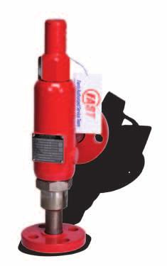
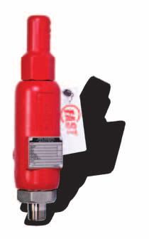
12 Farris Aftermarket Services FAST Track Turnaround Farris Engineering is dedicated to making our FAST Program work for you, which is why we have the FAST Track Center at our headquarters in Brecksville, OH. For urgent service requirements, our FAST Track Center has a large inventory of spare parts, finished valves, and dedicated machining and material resources. Farris can provide quick turnaround on inventory and machined parts for both current and obsolete valve designs. FAST Centers Our FAST Centers are a global network of independently owned and operated valve repair facilities offering: Total valve replacement, service and repair any hour, any day: 24/7 365 Local pressure relief valve inventories, plus a Web-accessible global inventory Factory trained, ASME and VR certified professionals Asset management solutions to keep plants safe Look for the FAST tag, your assurance for quality and safety. New valve FAST tags In the US or Canada contact FARRIS1 or to find the location of your nearest FAST Center, or for a global listing go to Repair valve FAST tags Brecksville Road, Brecksville, OH USA Telephone: Fax: Facilities: Brecksville, Ohio, USA; Brantford, Ontario, Edmonton, Alberta, Canada; Bridport, Dorset, UK; Delhi, India; Tianjin, Beijing, China; Dubai, U.A.E. Offices Worldwide: For a listing of our global sales network, visit our website at While this information is presented in good faith and believed to be accurate, Farris Engineering, division of Curtiss-Wright Flow Control Corporation, does not guarantee satisfactory results from reliance on such information. Nothing contained herein is to be construed as a warranty or guarantee, expressed or implied, regarding the performance, merchantability, fitness or any other matter with respect to the products, nor as a recommendation to use any product or process in conflict with any patent. Farris Engineering, division of Curtiss-Wright Flow Control Corporation, reserves the right, without notice, to alter or improve the designs or specifications of the products described herein Farris Engineering Printed in U.S.A. 11/10 3M R2
13 Series 2700 Maintenance Manual 197T R2 Addendum Packed Lever Design Drawing Update Bill of Materials Cap Construction Item No. Part Name Standard Materials M40 Packed Lever 7 Test Lever Steel 8 Cap, Packed Lever Steel 9 Stem Test Washer St. St. 10 Stem Jam Nut St. St. 11 Cam St. St. 12 Gland St. St. 13 Gland Nut St. St. 14 Packing Ring Graphite 15 Gland Nut Gasket Flexible Graphite 16 Groove Pin Steel Plt d 17 Retaining Ring St. St. Lifting Lever Assemblies B. Packed Lifting Lever (Figure 1.6) 1. Remove groove pin from lever and slide lever off the cam. 2. Remove retaining ring from cam. 3. Remove gland from gland nut. Unscrew gland nut from cap and remove packing ring and cam. If any signs of leakage exist, replace packing ring. 4. Break wire seal and unscrew cap from bonnet. Holding stem with smooth jaw pliers, remove stem jam nut and stem test washer. 5. Reassemble in reverse order, making sure the cam lobe is pointing down. Stem test washer should be adjusted to ensure the cam will make contact with stem test washer and lift stem when lever is actuated. 7 Packed Lever Construction Figure correction
14 Appendix A correction Critical Seat and Disc Dimensions Use these dimensions when lapping and/or refacing is required. Parts must be replaced if the minimum dimension is reached as indicated in the drawings. Orifice Letter Size C 1/2 x 1 3/4 x 1 1 x 1 D 1/2 x 1 3/4 x 1 1 x 1 A B Body Dimensions C D L H Disc Dimensions J K N E 1 x 1 1/ F 1 1/2 x G 1 1/2 x 2 1/ General Notes: 1. All dimensions are in inches. 2. Dimensions for body apply to both metal seat and O-ring seat designs. 3. Above dimensions apply to both standard and high pressure versions. DISC N 15º H J K D C B A 45º L Bonnet Thread Connection BODY 11 correction
Pressure Relief Valve Maintenance Manual
 Technical Manual 1098T Pressure Relief Valve Maintenance Manual Farris Engineering Division of Curtiss-Wright Flow Control Corporation TABLE OF CONTENTS - Manual Revision 0 Introduction & Safety Tips...
Series Maintenance Manual. Technical Manual 806T R1
 Series 4200 Maintenance Manual Technical Manual 806T R1 Table of Contents Introduction Numbering System...1 Bill of Materials...2 Disassembly...3 Nozzle & Disc Refacing/Lapping Nozzle Refacing...4 Disc
394C. Series 6400/6600. Safety Valves for Power Boiler Service
 394C Series 6400/6600 Safety Valves for Power Boiler Service Series 6400/6600 Designed with the user in mind, Series 6400 and 6600 safety valves represent the most advanced technology in valves designed
Series Pressure Relief Valves 197C
 Series 2700 Pressure Relief Valves 197C Table of Contents General Description...IFC Ordering Information & Numbering System...1 Bill of Materials-Conventional...2 Bill of Materials-Balanced Design...3
Series Safety Valves for ASME Section I and VIII Boiler Applications 1005C
 Series 4200 Safety Valves for ASME Section I and VIII Boiler Applications 1005C Table of Contents Introduction & Warranty...IFC Numbering System & Ordering Information...1 Features & Benefits...2 Bill
Series Safety Valves for ASME Section I and VIII Boiler Applications 1005C
 Series 4200 Safety Valves for ASME Section I and VIII Boiler Applications 1005C Table of Contents Introduction & Warranty...IFC Numbering System & Ordering Information...1 Features & Benefits...2 Bill
304C. Valve Group. Series Farris Engineering Pressure Relief Valves
 304C Valve Group Series 600 Farris Engineering Pressure Relief Valves Type Numbering System Our type numbering system simplifies the selection and specifying of Farris pressure relief valves because the
197C. Valve Group. Series Farris Engineering Pressure Relief Valves
 97 Valve Group Series 700 Farris Engineering Pressure Relief Valves Numbering System Selecting and specifying Farris pressure relief valves is simple using the numbering system that follows. Each digit
Crosby Series 800 and 900 OMNI-TRIM Pressure Relief Valves. Flow Control
 Crosby s Series 800 adjustable blowdown and Series 900 fixed blowdown OMNI-TRIM full nozzle pressure relief valves have a simplified, single trim design with superior application versatility. Features
CROSBY SERIES 800 AND 900 OMNI-TRIM PRESSURE RELIEF VALVES INSTALLATION AND MAINTENANCE INSTRUCTIONS
 any and all liability arising out of the same. Any installation, maintenance, adjustment, repair and testing performed on pressure relief valves should be done in accordance with the requirements of all
Crosby Series BP OMNI-TRIM Pressure Relief Valves for applications involving variable back pressure.
 CROSBY Crosby Series BP OMNI-TRIM Pressure Relief Valves for applications involving variable back pressure. Features The balanced piston design offsets the effects of variable back pressure on valve set
* Contact your sales representative for compliance to NACE MR or later requirements.
 VALVES & CONTROLS crosby SERIES 00, 00 OMNI-TRIM, AND BP OMNI-TRIM Crosby s Series 00 adjustable blowdown, Series 00 fixed blowdown OMNI-TRIM, and BP OMNI-TRIM full nozzle pressure relief valves have a
ANDERSON GREENWOOD SERIES 500 PILOT OPERATED SAFETY RELIEF VALVES INSTALLATION AND MAINTENANCE INSTRUCTIONS
 Before installation these instructions must be fully read and understood TABLE OF CONTENTS 1. General valve description and start-up... 1 2. Main valve maintenance... 1 3. Pilot maintenance... 5 4. Pilot
* Contact your sales representative for compliance to NACE MR or later requirements.
 VALVES & CONTROLS crosby SERIES 800, 900 OMNI-TRIM, AND BP OMNI-TRIM Crosby s Series 800 adjustable blowdown, Series 900 fixed blowdown OMNI-TRIM, and BP OMNI-TRIM full nozzle pressure relief valves have
Table of Contents Visual Inspection and Neutralizing... 3 Disassembly
 1 Table of Contents Visual Inspection and Neutralizing... 3 Disassembly... 3... 4... 4 Cleaning... 4 Inspection... 4 Reconditioning of Valve Seats... 5 Lapping Procedures... 5 Lapping Blocks... 5 Lapping
Baumann Series Flexsleev Control Valve Instructions
 Instruction Baumann 86000 Series Instructions Baumann 86000 Series Flexsleev Control Valve Instructions Contents Introduction...1 Scope...1 Safety Precautions...1 Maintenance...2 Installation...3 Air Piping...3
INSTRUCTION MANUAL. Anchor Darling 1878 Swing Check Valves. Installation Operation Maintenance. Sizes 1/2 through 2 FCD ADENIM
 INSTRUCTION MANUAL Anchor Darling 1878 Swing Check Valves Sizes 1/2 through 2 Installation Operation Maintenance FCD ADENIM0006-00 Table of Contents 1.0 Physical Description and Operation of Equipment
Spring loaded Thermal Relief Safety Valves, manufacturers standard Medium and high pressure
 Series Thermal Relief Safety Valves Spring loaded Thermal Relief Safety Valves, manufacturers standard Medium and high pressure Applications The Sempell series provides a complete and comprehensive range
Series Maintenance Manual. Technical Manual 802T R2
 Series 3800 Maintenance Manual Technical Manual 802T R2 Table of Contents Introduction...2 Safety Tips...2 Type Numbering System...3 Operational Principles...3 Main Valve...4 Bill of Materials...4 Disassembly...5
Baumann 24000C Carbon Steel Little Scotty Control Valve Instructions
 Instruction Manual D103356X012 24000C Control Valve Baumann 24000C Carbon Steel Little Scotty Control Valve Instructions CONTENTS Introduction...1 Scope...1 Safety Precautions...1 Maintenance...2 Flow
Crosby Series HSJ safety valves Installation, operation and maintenance instructions
 Before installation these instructions must be fully read and understood Warning The safety of lives and property often depends on the proper operation of the safety valves. Consequently, the valves should
CROSBY SERIES BP OMNI-TRIM PRESSURE RELIEF VALVES INSTALLATION, MAINTENANCE AND ADJUSTMENT INSTRUCTIONS
 Before installation these instructions must be read fully and understood cause misalignment of the valve parts. It is recommended that the valves be left in their original shipping containers and that
ANDERSON GREENWOOD. Before installation these instructions must be fully read and understood.
 ANDERSON GREENWOOD Before installation these instructions must be fully read and understood. 1.1 General The Anderson Greenwood Series 200 Pilot Operated SRV uses the principle of pressurizing the larger
HIGH PRESSURE CONTROL VALVE PISTON BALANCED
 PISTON BALANCED All Rights Reserved. All contents of this publication including illustrations are believed to be reliable. And while efforts have been made to ensure their accuracy, they are not to be
Anderson Greenwood Series 800 POSRV Installation and Maintenance Instructions
 Before installation these instructions must be fully read and understood Table of contents 1. General valve description and start-up... 1 2. Main valve maintenance... 2 3. Pilot maintenance... 6 4. Pilot
SV80H Safety and Relief Valves
 Page 1 of 18 BR Rev.02 U SH Safety and Relief alves Description The SH is a full nozzle safety and relief valve with orifices D to T, comply with the API STD 526, beyond others with super capacity. Suitable
INSTALLATION, OPERATION, MAINTENANCE MANUAL FOR MANUALLY OPERATED STOP CHECK VALVE
 INSTALLATION, OPERATION, MAINTENANCE MANUAL FOR MANUALLY OPERATED STOP CHECK VALVE Page 1 of 13 1.1 General CHAPTER 1 - GENERAL INFORMATION This manual contains maintenance instructions with pertinent
INSPECTION & MAINTENANCE BULLETIN ARI 1301/1302 1" Plug Type Angle Valves
 INSPECTION & MAINTENANCE BULLETIN ARI 1301/1302 1" Plug Type Angle Valves Item # Description Item # Description 1 Body 12 Washer 2 Packing Retainer 13 Bushing 3 Packet Set 14 Bolt 4 Jam Nut 15 Yoke 5 Stud
Pressure Relief Valves. 1541/1543 Series. Consolidated Safety Valve
 Pressure Relief Valves 1541/1543 Series Consolidated Safety Valve Table of Contents Conversion Table 1541/1543.2 Features & Benefits 1541/1543.3 Applications 1541/1543.3 Scope of Design 1541/1543.4 Materials
Anderson Greenwood Series 400 Piston Pilot POPRV Installation and Maintenance Instructions
 Before installation these instructions must be fully read and understood As capacity relief of the system is satisfied, system pressure will begin to decrease. When it does, the pilot will actuate and
J Flow Controls Model Numbering
 4665 Interstate Dr Cincinnati, OH 45246 Phone 513-731-2900 Fax 513-731-6939 3500 Series Valve Instruction and Maintenance Manual Caution: Prior to performing any repairs or maintenance on the valve assembly,
PFA LINED BALL VALVES Installation, Operation and Maintenance Manual
 ACRIS PFA LINED BALL VALVES WWW.AMRESIST.COM Table of Contents Safety Instructions - Definition of Terms............................................2 Introduction..............................................................2
Baumann 24000F Wafer Control Valve
 Instruction Manual 24000F Valves Baumann 24000F Wafer Control Valve Contents Introduction... 1 Scope of Manual... 1 Safety Precautions... 2 Maintenance... 2 Installation... 3 Air Piping... 3 Disassembly...
BETTIS SERVICE INSTRUCTIONS DISASSEMBLY AND REASSEMBLY FOR CB-SR-S SEISMIC SPRING RETURN SERIES PNEUMATIC ACTUATORS
 BETTIS SERVICE INSTRUCTIONS DISASSEMBLY AND REASSEMBLY FOR CB-SR-S SEISMIC SPRING RETURN SERIES PNEUMATIC ACTUATORS PART NUMBER: 102264 REVISION: "C" DATE: November 2000 Page 1 of 11 1.0 INTRODUCTION 1.1
Table of Contents. 1900/P3 Series Exposed spring design - The spring in this design is exposed for atmospheric cooling. D through T orifice sizes.
 Scope of Design Table of Contents Scope of Design...............................................................1900P.1 Materials 1900/P1 (Conventional)......................................................1900P.3
Ideal Installation. I & M Mark 67 (1/2 6 ) Control Line. Installation & Maintenance Instructions for Mark 67 Pressure Regulators
 Control Line. Installation & Maintenance Instructions for Mark 67 Pressure Regulators") I & M Mark (/ ) 0 Wasson Road Cincinnati, OH 0 USA Phone --00 Fax -8-00 info@richardsind.com www.jordanvalve.com Installation & Maintenance Instructions for Mark Pressure Regulators Warning: Jordan Valve
I & M Mark (/ ) 0 Wasson Road Cincinnati, OH 0 USA Phone --00 Fax -8-00 info@richardsind.com www.jordanvalve.com Installation & Maintenance Instructions for Mark Pressure Regulators Warning: Jordan Valve
for ½" thru 2" 800 lb. Piston Lift Check Valves with Resilient Seat Option
 Manual No. 800-PC Issued: March 31, 2004 INSTRUCTION MANUAL for ½" thru 2" 800 lb. Piston Lift Check Valves with Resilient Seat Option Flowserve Corporation Flow Control Division 1900 S. Saunders Street
LOW PRESSURE BALANCED VALVE DIAPHRAGM BALANCED
 DIAPHRAGM BALANCED All Rights Reserved. All contents of this publication including illustrations are believed to be reliable. And while efforts have been made to ensure their accuracy, they are not to
Installation, Operation and Maintenance Guide II NIBCO High Performance Butterfly Valves Series 6822 and 7822
 Installation, Operation and Maintenance Guide II NIBCO High Performance Butterfly Valves Series 6822 and 7822 Statements: NIBCO High Performance Butterfly Valves, Series 6822 and 7822, have been designed
2900 MPV Series. Consolidated * Valves. Pilot-Operated Safety Relief Valve
 GE Oil & Gas Technical Specifications 08/2014 Consolidated * Valves 2900 MPV Series Pilot-Operated Safety Relief Valve A unique design that combines top performance, capabilities and features within an
Kunkle Models 189/363/389 safety valves Safety and relief products
 Heavy duty ASME Section VIII, air/gas cryogenic, UV, National Board certified safety valves Model 189 Features Heavy duty construction provides long service life. Unique three-piece disc assembly with
METERING VALVE 2" STEM GUIDED
 2" STEM GUIDED All Rights Reserved. All contents of this publication including illustrations are believed to be reliable. And while efforts have been made to ensure their accuracy, they are not to be construed
Anderson Greenwood Series 5100 Pilot Operated Pressure Relief Valves
 ANDERSON GREENWOOD Series 5100 Modulating Safety Relief Valve Anderson Greenwood has developed the revolutionary Series 5100 specifically to serve Economizer applications requiring pressure relief under
Anderson Greenwood Series 727 Pilot Operated Safety Relief Valves Installation and Maintenance Instructions
 Before installation these instructions must be fully read and understood Table of contents 1 General valve description... 2 2 Main valve maintenance... 2 3 Pilot maintenance... 7 4 Pilot set pressure adjustment...
Series Pressure Relief Valves. Farris Engineering Products and Services 304C
 304C Series 2600 Farris Engineering Products and Services Pressure Relief Valves Process Pressure Relief Valves Series 2600 ASME NB Certified for Air, Steam, and Water Series 3800 ASME NB Certified for
Baumann Little Scotty Bronze Control Valve
 Instruction Manual 24000 Valve Baumann 24000 Little Scotty Bronze Control Valve Contents Introduction... 1 Scope of Manual... 1 Safety Precautions... 2 Maintenance... 2 Installation... 3 Air Piping...
Baumann Mikroseal Control Valve
 Instruction Manual 81000 Valve Baumann 81000 Mikroseal Control Valve Contents Introduction... 1 Scope of Manual... 1 Safety Precautions... 2 Maintenance... 3 Installation... 3 Air Piping... 4 Flow Direction...
Baumann 24000CVF Carbon & 24000SVF Stainless Steel Flanged Valve Instructions
 Instruction Manual D103360X012 24000CVF/SVF Control Valve Baumann 24000CVF Carbon & 24000SVF Stainless Steel Flanged Valve Instructions CONTENTS Introduction...1 Scope of Manual...1 Safety Precautions...1-2
Crosby Style HCI ISOFLEX Safety Valves Installation, Maintenance and Adjustment Instruction CROSBY
 CROSBY (For valves purchased prior to January 1, 1998 see IS-V 3143A) Table of contents Ordering Spare Parts 1 Safety Precautions 1 Crosby Style HCI-ISOFLEX - Parts 2 Introduction 3 Description of Safety
Operation and Maintenance Manual
 Operation and Maintenance Manual MODEL S-216-J-( ) Series AIR-DRIVEN HYDRAULIC PUMP ISSUED NOVEMBER 1994 Revised February 2005 Sprague Products Division of Curtiss-Wright Flow Control Corporation 10195
Type 63EG-98HM Pilot-Operated Relief Valve or Backpressure Regulator
 Instruction Manual Form 5475 Type 63EG-98HM October 009 Type 63EG-98HM Pilot-Operated Relief Valve or Backpressure Regulator! WARNING Failure to follow these instructions or to properly install and maintain
Fisher RSS Lined Globe Valve
 Instruction Manual D0990 November 009 RSS Valve Fisher RSS Lined Globe Valve Contents Introduction............................... Scope of Manual.......................... Description...............................
Baumann Sanitary Angle Control Valve
 Baumann 83000 Sanitary Angle Control Valve Contents Introduction... 1 Scope of Manual... 1 Safety Precautions... 2 Educational Services... 2 Maintenance... 3 Installation... 3 Air Piping... 4 Flow Direction...
SAFETY relief VALVE SERIES # 006 DESIGN FEATURES HARSHAD ENGINEERING WORKS HARSHAD ENGINEERING WORKS TECHNICAL DATA : ISO 9001 CERTIFIED COMPANY
 PROVIDES HIGH QUALITY OVERPRESSURE PROTECTION FOR AIR, GAS, LIQUID & STEAM IN SINGLE STANDARDIZED DESIGN SAFETY relief VALVE DESIGN FEATURES SAFETY VALVE MANUFACTURED IN ACCORDANCE WITH REQUIREMENT OF
Pressure Relief Valves Series. Consolidated Safety Valve
 Pressure Relief Valves 1511 Series Consolidated Safety Valve Consolidated Type 1511 safety valves are designed for low pressure, steam heating boilers and steam generators as well as air service applications.
2900 MPV Series. Consolidated * Valves. Pilot-Operated Safety Relief Valve
 Technical Specifications Rev.A - 07/2018 Consolidated * Valves 2900 MPV Series Pilot-Operated Safety Relief Valve A unique design that combines top performance, capabilities and features within an economical,
Crosby Styles HC and HCA ISOFLEX safety valves Installation, maintenance and adjustment instructions
 Before installation these instructions must be read fully and understood Table of contents 1. Style HC/HCA ISOFLEX - parts... 2 2. Introduction... 3 3. Description of safety valve... 4 4. Storage... 4
Edward Valves. Maintenance Manual for Edward Forged Steel Valves. Bolted and Screwed Bonnet Types V-376 R3
 Maintenance Manual for Edward Forged Steel Valves Bolted and Screwed Bonnet Types V-376 R3 Contents Servicing Edward Forged Steel Valves...3 Introduction...4 Seats and Seat Finishing...5 Disks and Disk
Crispin Valves Operating Guide. Crispin
 Crispin Valves Operating Guide Crispin Since 1905 Crispin Multiplex Manufacturing Co. 600 Fowler Avenue Berwick, PA 18603 1-800-AIR-VALV T: (570) 752-4524 F: (570) 752-4962 www.crispinvalve.com sales@crispinvalve.com
PRESSURE REGULATOR BACK PRESSURE TO ATMOSPHERE WITH OUTSIDE SUPPLY
 PRESSURE REGULATOR BACK PRESSURE TO ATMOSPHERE WITH OUTSIDE SUPPLY All Rights Reserved. All contents of this publication including illustrations are believed to be reliable. And while efforts have been
Product Manual. CVS Series D Globe and Series DA Angle Style Valves. Introduction. Applications and Features
 Product Manual CVS Series D Globe and Series DA Angle Style Valves Introduction Contained in this manual are installation instructions, maintenance procedures and parts information for the -inch and 2-inch
MERCER VALVE SERIES Flanged THINK...MERCER FIRST MERCER VALVE CO., INC. AUTO SEAT TECHNOLOGY
 9100 SERIES Flanged THINK...MERCER FIRST MERCER VALVE MERCER VALVE CO., INC. AUTO SEAT TECHNOLOGY 9100 Series Product Overview The Mercer Valve 9100 Series Pressure Relief Valve is State of the Art in
Anderson Greenwood MB Series Integral Manifolds
 A range of 2, 3 or 5-valve integral manifolds for connection to bottom inlet, low-profile pressure transmitters Features MB2 General application MB3 The MB series includes 2 valve manifolds for static
Baumann Sanitary Diaphragm Angle and Inline Control Valve
 Instruction Manual 84000 Valve Baumann 84000 Sanitary Diaphragm Angle and Inline Control Valve Contents Introduction... 1 Scope of Manual... 1 Safety Precautions... 2 Maintenance... 2 Flow Direction...
I & M 8000 Series. Ideal Installation Schematic. Preferred Installation. Trouble Shooting
 I & M 8000 Series 3170 Wasson Road Cincinnati, OH 45209 USA Phone 513-533-5600 Fax 513-871-0105 lowflow@richardsind.com www.lowflowvalve.com Installation & Maintenance Instructions for 8000 Series Low
9100 SERIES Flanged MERCER VALVE THINK...MERCER FIRST
 9100 SERIES Flanged MERCER VALVE THINK...MERCER FIRST 9100 Series Product Overview The Mercer Valve 9100 Series Pressure Relief Valve is State of the Art in soft seat, high flow rate, pressure relieving
FORGED HIGH PRESSURE BONNETLESS. ASME CLASSES: Sizes: 1 2 4" ( mm) U.S. Patent # Patented Easy Maintenance!
 U.S. Patent # Patented Easy Maintenance!") FORGED HIGH PRESSURE BONNETLESS ASME CLASSES: 1690 4500 Sizes: 1 2 4" (15 100 mm) U.S. Patent # 4356832 Patented Easy Maintenance! PROFILE Velan is one of the world's leading manufacturers of industrial
FORGED HIGH PRESSURE BONNETLESS ASME CLASSES: 1690 4500 Sizes: 1 2 4" (15 100 mm) U.S. Patent # 4356832 Patented Easy Maintenance! PROFILE Velan is one of the world's leading manufacturers of industrial
494C. Pilot Operated Pressure Relief Valves. Series Pilot Operated Pressure Relief Valves. Farris Engineering Pressure Relief Valves
 Series 3800 Pilot Operated Pressure Relief Valves 494C Pilot Operated Pressure Relief Valves Farris Engineering Pressure Relief Valves Piloting the Way to Precision Control The innovative, integrally cast,
General Specifications
 General Specifications GS 22B01C52-01EN-A M-650, M-750 and M-651 3-Valve Manifolds for Differential Pressure INTRODUCTION The PGI 3-Valve manifolds are designed for mounting on differential pressure transmitters
1541/1543 Series. Consolidated * Valves. Safety Valve
 GE Oil & Gas Technical Specifications 11/2014 Consolidated * Valves 1541/1543 Series Safety Valve Designed for steam and other compressible fluids, these valves are most commonly used in pharmaceutical,
Fisher RSS Lined Globe Valve
 Instruction Manual D0990 RSS Valve July 07 Fisher RSS Lined Globe Valve Contents Introduction... Scope of Manual... Description... Educational Services... Specifications... Installation... Maintenance...
MODEL 5540 CONTENTS. Installation, Operation and Maintenance Instructions 1.0 GENERAL
 Installation, Operation and Maintenance Instructions MODEL 5540 Sep 20 CONTENTS.0 GENERAL. Model Number---------------------------------------------------------------------------------------------------------------
Installation, Operation and Maintenance Instructions Series 608 Ball Valve
 b. With valve open, remove three body bolts, loosen fourth and swing out body. Remove fourth bolt and spread pipe ends Close valve, remove ball, seats, body seals. Return body to its original position
Kunkle Safety and Relief Products
 ASME Section I and VIII, Steam, V and UV, ASME Section VIII, Air/Gas UV National Board Certified. Models 6933, 6934, and 6935 are ASME Section IV, Steam, HV National Board Certified. PED Certified for
ANDERSON GREENWOOD M4AP/M4TP STATIC PRESSURE MANIFOLDS
 ANDERSON GREENWOOD M4AP/M4TP STATIC PRESSURE MANIFOLDS Block and bleed, two valve manifolds with indirect and direct mount capabilities for static pressures to 6000 psig (414 barg) FEATURES GENERAL APPLICATION
Multi-Port Gauge Valves M5 and M51
 Multi-Port Gauge Valves M5 and M51 M5 Product Overview The M5 and M51 are multi-port gauge valves allowing the versatile positioning of gauges or pressure switches without requiring additional penetration
Direct contact, metal-to-metal seating, make the gate valve ideal for most shut-off applications. Class 800 ANSI.
 Direct contact, metal-to-metal seating, make the gate valve ideal for most shut-off applications. Class 800 ANSI. Features Two inch and smaller valves are available with threaded or socket weld ends as
Table of Contents. Introduction. Description. Greater Total System Efficiency. Improved Design. Easy Installation and Maintenance
 Features & Benefits Table of Contents Features & Benefits................................................................ 13900.1 Scope of Design...................................................................
CROSBY STYLE JB PRESSURE RELIEF VALVE
 A large orifice pressure relief valve engineered to provide high quality, dependable overpressure protection for air, gas, vapor and steam applications FEATURES Ten size product range is the broadest available.
Series Pilot Operated Pressure Relief Valves 0810C
 Series 00 Pilot Operated Pressure Relief Valves 00C Numbering System To simplify the selection and specifying of Farris pressure relief valves, use the following type numbering system. The type numbering
Baumann Way Control Valve
 Instruction Manual 24003 Valve Baumann 24003 3-Way Control Valve Contents Introduction... 1 Scope of Manual... 1 Safety Precautions... 2 Educational Services... 3 Maintenance... 3 Installation... 3 Air
Baumann Sanitary Diaphragm Angle & In-Line Control Valve Instructions
 Instruction Manual D103370X012 84000 Control Valve Baumann 84000 Sanitary Diaphragm Angle & In-Line Control Valve Instructions CONTENTS Introduction...1 Scope...1 Safety P recautions...1 Maintenance...2
BETTIS SERVICE INSTRUCTIONS DISASSEMBLY AND REASSEMBLY FOR CB-SR SPRING RETURN SERIES PNEUMATIC ACTUATORS
 ENGLISH LANGUAGE BETTIS SERVICE INSTRUCTIONS DISASSEMBLY AND REASSEMBLY FOR CB-SR SPRING RETURN SERIES PNEUMATIC ACTUATORS PART NUMBER: 068270E REVISION: "C" RELEASE DATE: December 2001 Page 1 of 12 CONTENTS
Standard Valves Series Globe Valves Series Angle Valves Series Way-Valves
 Installation, Operation, Maintenance Instructions Standard Valves Series 035 000 Globe Valves Series 031 000 Angle Valves Series 033 000 3-Way-Valves 1 GENERAL INFORMATION These instructions are designed
CV Control Valves Installation and Operation Manual
 CV1500 - Control Valves Installation and Operation Manual 652-EN Overview Warning: This bulletin should be used by experienced personnel as a guide to the installation of the Armstrong CV1500 Control Valve.
GH-BETTIS SERVICE INSTRUCTIONS DISASSEMBLY & REASSEMBLY FOR MODELS HD521-M4, HD721-M4 AND HD731-M4 DOUBLE ACTING SERIES PNEUMATIC ACTUATORS
 GH-BETTIS SERVICE INSTRUCTIONS DISASSEMBLY & REASSEMBLY FOR MODELS HD521-M4, HD721-M4 AND HD731-M4 DOUBLE ACTING SERIES PNEUMATIC ACTUATORS WITH HYDRAULIC CONTROL PACKAGE PART NUMBER: SE-023 REVISION:
Needle Valves. Catalog 1203/1205 Aug 2012
 Catalog 1203/1205 Aug 2012 Visual Index Click on link for desire page. At present image not available BAX-NVFF-01 FEMALE FEMALE Page 8 BAX-NVAMF-05 MALE FEMALE (ANGLE TYPE) Page 12 BAX-NVMFD-09 MALE -
Models 910, 911, 916, 917, 920, 921, 927 ASME Section VIII, Air/Gas/
 Models 910, 911, 916, 917, 920, 921, 927 ASME Section VIII, Air/Gas/ Steam/Liquid, UV National Board Certified. Also available for Vacuum Service Model 921: Steel body and bonnet with plain lift lever
Tri-Pac E325 / E525 Ball Valve Three-Piece Bolted Body, In-Line Maintainable, Regular and Full Port. McCANNA/MARPAC Valves RO400-R4
 RO400-R4 AN ISO 9001 REGISTERED COMPANY Tri-Pac E325 / E525 Ball Valve Three-Piece Bolted Body, In-Line Maintainable, Regular and Full Port MARPAC by McCANNA Tri-Pac E325/E525 Ball Valves DESIGN FEATURES
Table of Contents 1. Introduction. 2. Storage and Handling. 3. Installation Care in Handling Inspection Inlet Piping Outlet Piping
 SAPAG Table of Contents 1. Introduction 2. Storage and Handling Attention The safety of lives and property often depends on the proper operation of the pressure relief valves. Consequently, the valves
HOKE Monoflange Valves. Primary Isolation Valves
 HOKE Monoflange Valves Primary Isolation Valves Table of Contents Conventional Double Block & Bleed Assembly... 3 Applications, Specifications, Features & Benefits... 4 Features Cutaway... 5 HOKE Integral
Design CP Control Valve with ENVIRO-SEAL Bellows Seal Bonnet
 Instruction Manual Form 5410 November 1998 Design CP/ENVIRO-SEAL Bellows Seal Design CP Control Valve with ENVIRO-SEAL Bellows Seal Bonnet Contents Introduction.............................. 1 Scope of
2200 North Main Street Washington, PA PH: FX:
 2200 North Main Street 2200 North Main Street KVAB SERIES MEDICAL VALVES All valves MRI compatible - approved to 3 Tesla. Nominal stroke is 1.5 turns. Full flow at ⅓ turn. Strong, durable body is made
Installation Instructions
 Installation Instructions X-100 Single cartridge mounted welded metal bellows seal Experience In Motion Congratulations You have just purchased a reliable, long-life product manufactured by the leading
INSTALLATION AND MAINTENANCE OF TOP LOADING ARM
 INSTALLATION AND MAINTENANCE OF TOP LOADING ARM D TABLE OF CONTENTS 1. INTRODUCTION 04 2. SPECIFICATION OF THE REDLANDS LOADING ARM 04 3. INSTALLING THE LOADING ARM 3.1. Installation Procedures 05 4.
INSTALLATION & MAINTENANCE MANUAL
 INSTALLATION & MAINTENANCE MANUAL 3-WAY/4-WAY/5-WAY MULTI-PORT BALL VALVES T TEFLON PARTS - 1. Seat x 5 pcs. 2. Joint Gasket x 5 pcs. 3. Retainer Seal x 5 pcs. 4. Thrust Washer x 1 pc. 5. O-Ring x 1 pc
SEMPELL HIGH PRESSURE CHECK VALVE MODEL VR500 (ASME)
") Designed for use in high temperature and high pressure systems wherever a reverse flow has to be avoided. FEATURES Piston type check valve Body made of forged steel Wear resistant stellite body seat Separated
Designed for use in high temperature and high pressure systems wherever a reverse flow has to be avoided. FEATURES Piston type check valve Body made of forged steel Wear resistant stellite body seat Separated
INSPECTION & MAINTENANCE BULLETIN ARI Plug Type Angle Valves
 INSPECTION & MAINTENANCE BULLETIN ARI 1316 2 Plug Type Angle Valves Item # Description Item # Description Item # Description 1 Body 12 Top Stem Nut 23 Seat Gasket 2 Valve Disc 13 Handwheel 24 Valve Seat
Consolidated* Series
 Technical Specifications Rev. C - 10/2018 Consolidated* 2900-40 Series Pilot-Operated Safety Relief Valve BHGE Data Classification : Public Table of Contents Conversion Table...2 Scope of Design...3 Main
13900 Series. Consolidated * Valves. Pilot-Operated Safety Relief Valve
 GE Oil & Gas Technical Specifications 08/2014 Consolidated * Valves 13900 Series Pilot-Operated Safety Relief Valve Designed specifically for high capacity steam applications, this series of valves contributes