Technical Documentation. Technology in Motion FLAMEPROOF FLAMEPROOF F L A M E P ROOF FPM FPM
|
|
|
- Wilfred Griffin
- 6 years ago
- Views:
Transcription


1 FLAMEPROOF FPM MOTOR S Technical Documentation N O R D E N H A M F L A M E P ROOF T H R E E - P H AS E M OTO RS Technology in Motion F L A M E P ROOF T H R E E - P H AS E M OTO RS FPM FLAMEPROOF MOTOR S N O R D E N H A M

2 We don t just manufacture motors. We turn our customer s ambitious ideas into modern, innovative products which are as unique as they are revolutionary. We get you there with our blend of reliability, creativity and flexibility.
3 Index 3 General Information I Construction Type Versions, Special-Purpose Motors II Electrical Design III Operating Characteristics IV Operating Data Low-Voltage Motors V High-Voltage Motors VI Dimensions VII Spare Parts VIII Conversions and Formulae IX Service Partners X
4 Contents 4 I General Information Energy efficiency 6 Certificates and standards 8 Explosion protection types of electrical machines 10 Explosion protection types and categories of electrical machines 12 Type code 16 Construction Type Mountings 17 Materials, plates and labeling 18 Installation at normal, high and low temperatures 19 Protection types, paintwork, tropicalized version 20 Terminal boxes 21 Direct cable connection 23 Bearings 24 Bearing arrangement 25 Bearing and seal arrangement 26 Permissible radial load, deep groove ball bearing 27 Permissible axial load, deep groove ball bearing 28 Permissible radial load, cylindrical roller bearing 29 Rotor weights - CD series...(y2,y3,y) 30 Lubrication, bearing monitoring 31 Bearing eddy currents, insulated bearings, mechanical speed limits 32 Shaft ends, balancing, vibration amplitude, foundations 33 Operating noise levels, cooling air quantity 34 Special-purpose motors Low-noise motors 35 Low-noise motors, sound pressure level 36 On-deck installation with shipping classification 37 Flexi mount motor 38 Built-on and built-in equipment, tacho generator, reverse-running lock 39 Brake motors with integral brake 40 Brake motors with integral brake, direct transmission mounting 41 Brake motors with integral brake Three-phase AC asynchronous motors with integrated frequency inverter 42 Asynchronous motors 44 High-voltage motors 46 Electrical Design Safety devices, heating elements 48 Electrical design for motors up to 690 V 50 Operating Characteristics Operating characteristics for motors up to 690 V 51 Permissible start up times for air-cooled motors without brake, temperature class T4, protection through PTC thermistor temperature sensor 52 Permissible switching frequencies for standard motors, temperature class T4, protection through PTC thermistor temperature sensor 53 Frequency inverter operation 54 Torque characteristic on the frequency inverter, 50 Hz mains, Temperature class T4, 2p = 2 56 Torque characteristic on the frequency inverter, 50 Hz mains, temperature class T4, 2p = 4,6,8 57 Operating Data, Low-Voltage Motors Mains operation and inverter operation, IE1 mains operation (50 Hz) - temperature class T4, ns = 3000 rpm, 2p = 2 58 Inverter operation (50 Hz) - temperature class T4, ns = 3000 rpm, 2p = 2 59 IE1, mains operation (50 Hz) - temperature class T4, ns = 1500 rpm, 2p = 4 60 Inverter operation (50 Hz) - temperature class T4, ns = 1500 rpm, 2p = 4 61 IE1, mains operation (50 Hz) - temperature class T4, ns = 1000 rpm, 2p = 6 62 Inverter operation (50 Hz) - temperature class T4, ns = 1000 rpm, 2p = 6 63 IE1, mains operation (50 Hz) - temperature class T4, ns = 750 rpm, 2p = 8 64 Inverter operation (50 Hz) - temperature class T4, ns = 750 rpm, 2p = 8 65 IE2, mains operation (50 Hz) - temperature class T4, ns = 3000 rpm, 2p = 2 66 Inverter operation (50 Hz) - temperature class T4, ns = 3000 rpm, 2p = 2 67 IE2, mains operation (50 Hz) - temperature class T4, ns = 1500 rpm, 2p = 4 68 Inverter operation (50 Hz) - temperature class T4, ns = 1500 rpm, 2p = 4 69
5 5 IE2, mains operation (50 Hz) - temperature class T4, ns = 1000 rpm, 2p = 6 70 Inverter operation (50 Hz) - temperature class T4, ns = 1000 rpm, 2p = 6 71 IE3 / MEPS, mains operation (50 Hz) - temperature class T4, ns = 3000 rpm, 2p = 2 72 IE3 / MEPS, mains operation (50 Hz) - temperature class T4, ns = 1500 rpm, 2p = 4 73 IE3 / MEPS, mains operation (50 Hz) - temperature class T4, ns = 1000 rpm, 2p = 6 74 MEPS, mains operation (50 Hz) - temperature class T4, ns = 750 rpm, 2p = 8 75 Partial load data IE1 efficiency, power factor 76 IE2 efficiency, power factor 78 IE3/MEPS efficiency, power factor 80 Increased output, mains operation (50 Hz), Temperature class T4 ns = 3000 rpm, 2p = 2 82 ns = 1500 rpm, 2p = 4 83 Mains operation (50 Hz), temperature class T4 ns = 1500/3000 rpm, 2p = 4/2 84 ns = 1000/1500 rpm, 2p = 6/4 85 ns = 750/1500 rpm, 2p = 8/4 86 Fan version 87 Motors with integral brake, mains operation (50 Hz), temperature class T4 2p = 2, 4, 6, p = 8/4, 8/2 89 Motors with attached brake, mains operation (50 Hz), temperature class T4 Type CD...S, 2p = 2,4,6,8 90 Type CD...SV and...svn, 2p = 2,4,6,8 91 Brake coil data 92 Three-phase AC asynchronous motors with integrated frequency inverter 93 Noise class 4, water-cooled motors, mains operation (50 Hz), 2p = 2,4 94 Operating Data, High-Voltage Motors High-voltage motors, mains operation (50 Hz) 2p = 2,4,6,8 95 Dimensions Surface-cooled low-voltage motors, self-cooling through radial-flow fans, external cooling with axial-flow fan IE1, foot-mounting version 96 - IE2, IE3, MEPS foot-mounting version 98 IE1, flange design, FF version 100 IE2, IE3, MEPS flange design, FF version 102 IE1, flange design, FT version 104 IE2/IE3/MEPS, flange design, FT version 105 Self-cooling with axial-flow fan, noise classes 2 and 3 IE1, foot-mounting version 106 IE2, IE3, MEPS, foot-mounting version 108 IE1, flange design, FF version 110 IE2, IE3, MEPS, flange design, FF version 112 Water-cooled low-voltage motors Noise class Surface-cooled low-voltage motors Motors with integrated frequency inverter 116 Motors with integral brake, internal sensor 117 Motors with external brake, type CD...S 118 Motors with external brake type CD...SV and CD...SVN 119 Surface-cooled high-voltage motors Self-cooling with radial-flow fan 120 Terminal Boxes up to 690 V 121 Spare Parts Spare parts connections diagram 122 Circuit diagram 124 Conversions and Formulae Conversion of technical units 125 Service Partners Your service partners 126 I
6 Energy Efficiency 6 I Safety, longevity and eco-friendliness have always been deeply rooted in our corporate philosophy. This has led us to develop energy-efficient motors a long time ago, independent of the latest European directives regarding responsible use of energy and resources. IEC In an effort to harmonize the many different national efficiency requirements, the international standard IEC :2008 is a first step to achieve consistent international efficiency standards for three-phase low voltage motors in the output range from 0.75 kw and 375kW. There are now three International Efficiency classes: IE1, IE2, and IE3. IE3 has the strictest requirements, and even stricter requirements are being defined. The main difference between the former voluntary commitment of CEMEP, the European sector committee for electrical drives, from the year 1998 and today s international requirements is - apart from the reversed numbering - also the obligation to measure efficiency using the new procedures defined by IEC :2007. The scope of IEC includes motors with the following properties: 50 Hz and/or 60 Hz Rated voltages up to 1000 V Rated power from 0.75 kw to 375 kw 2, 4 or 6 poles S1 - continuous operation S3 - Periodic operation with operating periods > 80%. This does not include motors which have been specifically designed for inverter operation or which are an integral part of an assembly and can therefore not be tested separately. EuP Directive 2005/32/EC and ErP Directive 2009/125/EC The EuP directive is the legal basis for implementing the political objective to reduce CO 2 emissions in Europe (2005/32/EG, energy using products). It was modified in 2009 to focus on eco-friendly design of all products consuming energy (ErP directive; 2009/125/EG). The directive contains a number of different product-related implementing regulations. Motor regulation No. 640/2009 This regulation defines requirements for eco-friendly design of electrical motors and the use of electronic speed controls with respect to placing them on the market and commissioning them. These requirements also apply when the motors are incorporated into other products. The scope of application is limited compared with the IEC standard and there is a schedule for implementing the requirements. The ErP motor regulation does not apply to motors designed for use in a liquid; which are an integral part of an assembly and can therefore not be tested separately; which are operated in altitudes of more than 1000 meters above sea level; which are operated in ambient temperatures of more than 40 C; which reach operating temperatures exceeding 400 C; which are operated at ambient temperatures below -15 C (any type of motor); whose coolant temperatures are below 5 C or above 25 C at the inlet of a product; which are operated in potentially explosives atmospheres according to directive 94/9/EC (ATEX); brake motors. The different motor requirements will come into force according to the following schedule: On 16 June 2011, motors must meet at least the requirements of IE2. From 1 January 2015, motors with a rated power of 7.5 to 375 kw must either reach IE3 or IE2 and feature speed control. From 1 January 2017, motors with a rated power of 0.75 to 7,5 kw must either reach IE3 or IE2 and feature speed control. The statutory requirements only apply when the European manufacturer or importer introduces the motor to the market for the first time. Motors that are already available on the market may continue to be sold and commissioned after the effective date. While this is not mandatory for explosion-proof motors, our motors already meet the efficiency classes specified by IE today.
7 7 Depending on the design, our energy-saving motors are conform with the following efficiency requirements: 1. IE2 Level - High Efficiency according to IEC for international use (introduction on 16 June 2011). 2. IE3 Level - Premium Efficiency according to IEC for international use (introduction on 1 January 2011). 3. Minimum Energy Performance Standard (MEPS) according to AS/NZS for Australia and New Zealand. 4. High efficiency (Heff) according to AS/NZS for Australia and New Zealand. 5. Level 2 according to the China Energy Label base on GB Identification These types of motors have the letter Y in their designation and are labeled with the associated efficiency class IE and the rated efficiency, e.g. CD 80M1-2Y3 IE3-82.8%. The high level of efficiency is achieved by: 1. Larger diameters and longer stator cores with identical IEC mounting dimensions with respect to shaft height 2. Increased use of copper 3. Use of higher-quality electrical sheets 4. Use of shaft seals for protection types IP 55 and 56 with lower losses 5. Modified ventilation system for standard and low-noise versions (CD...A) I Type designation CD Y2 CD Y3 CD Y CD Y2 CD Y3 CD Y CD Y2 CD Y3 CD Y CD Y Output IEC IEC AS/NZS IEC IEC AS/NZS IEC IEC AS/NZS AS/NZS IE2 IE3 MEPS IE2 IE3 MEPS IE2 IE3 MEPS MEPS [kw] 2-polig 4-pole 6-pole 8-pole 0,75 77,4 80,7 78,5 79,6 82,5 80,5 75,9 78,9 76,0 71,8 1,1 79,6 82,7 80,6 81,4 84,1 82,2 78, ,3 74,7 1,5 81,3 84,2 82,6 82,8 85,3 83,5 79,8 82,5 79,9 76,8 2,2 83,2 85,9 84,1 84,3 86,7 84,9 81,8 84,3 81,9 79,4 3 84,6 87,1 85,3 85,5 87,7 86,0 83,3 85,6 83,5 81,3 4 85,8 88,1 86,3 86,6 88,6 87,0 84,6 86,8 84,7 82,8 5, ,2 87,2 87,7 89,6 87, ,1 84,5 7,5 88,1 90,1 88,3 88,7 90,4 88,9 87,2 89,1 87,3 86, ,4 91,2 89,5 89,8 91,4 89,9 88,7 90,3 88,7 87, ,3 91,9 90,3 90,6 92,1 90,8 89,7 91,2 89,6 88,9 18,5 90,9 92,4 90,8 91,2 92,6 91,2 90,4 91,7 90,3 89, ,3 92,7 91,2 91, ,6 90,9 92,2 90,8 90, ,3 92,0 92,3 93,6 92,3 91,7 92,9 91,6 91, ,5 93,7 92,5 92,7 93,9 92,8 92,2 93,3 92,2 91, , ,9 93,1 94,2 93,1 92,7 93,7 92,7 92, ,2 94,3 93,2 93,5 94,6 93,5 93,1 94,1 93,1 92, ,8 94,7 93, ,0 93,7 94,6 93,7 93, , ,2 94,2 95,2 94, ,9 94,2 94, ,3 95,2 94,5 94,5 95,4 94,7 94,3 95,1 94,5 94, ,6 95,4 94,8 94,7 95,6 94,9 94,6 95,4 94,8 94, ,8 95,6 95,0 94,9 95,8 95,2 94,8 95,6 95,1 95, ,8-95, ,8 - - Examples of different efficiency requirements (50 Hz)


8 Certificates and Standards 8 I We apply the most stringent quality criteria, which are checked annually by official government agencies. The certification of the quality assurance was implemented for the first time in Today we have certifications in accordance with: DIN EN ISO 9001:2008 for the Quality Management System and ATEX 95 according to 94/9/EG, Appendix IV for the production of totally enclosed flameproof motors. In order to ensure the universal application of the motors within future global markets, conformity certificates have been issued for the motors through various domestic and foreign certifications authorities. Explosion protection certifications e.g.: PTB for Europe GOST for Russia GOST for Belarus NEPSI for China TestSafe for Australia IECEx worldwide The conservation of our environment through the promotion of non-polluting manufacturing methods, materials and chemicals in energy-saving motors and drives was identified at an early stage and has been incorporated into the products. These activities, up to the employment of VOCoptimized paint, resulted in the following certification: DIN EN ISO 14001:2005 for the Environmental Management System Ship classification authorities e.g.: Germanischer Lloyd Lloyd's Register Nippon Kaiji Kyokai American Bureau of Shipping Russian Maritime Register of Shipping
9 9 All motors meet the following international standards and specifications. Apart from these guidelines, the motors also meet many customer specifications from the chemical and petrochemical and machine building industries. On request, motors can also be supplied according to the recommendations of the VIK (German association of industrial energy businesses). This makes our motors particularly suitable for the special service conditions of the basic materials industry or refineries. These motor types are labeled with VIK on the rating plate. I Standards Country International Europe Germany Title IEC International EN CENELEC DIN/VDE Electrotechnical European German Industrial Standard Commission Commitee for Association of Electotechnical German Standardisation Electrotechnicians Rotating electrical machines IEC EN DIN EN / Rating and operating behavior VDE 0530 Part 1 Process for determining losses and IEC EN DIN EN efficiency of rotating electrical VDE 0530 Part 2 machines by means of testing Protection types of rotating electrical machines IEC EN DIN EN / based on overall construction VDE 0530 Part 5 (IP code) - Introduction Classification of the cooling processes (IC code) IEC EN DIN EN / VDE 0530 Part 6 Classification of the design types, IEC EN DIN EN / the installation types and the VDE 0530 Part 7 terminal box location (IM-Code) Terminal markings and direction of rotation IEC EN DIN EN / VDE 0530 Part 8 Noise emission limit values IEC EN DIN EN / VDE 0530 Part 9 Starting performance of three-phase motors with IEC EN DIN EN / squirrel-cage rotor, VDE 0530 Part 12 except for pole-changing motors Mechanical vibrations of certain machines with a IEC EN DIN EN / shaft height of 56 mm and higher; VDE 0530 Part 14 measurement, evaluation and limit values of the vibration Efficiency classification of three-phase motors IEC EN DIN EN / with squirrel-cage rotors, VDE 0530 Part 30 except for pole-changing motors (IE code) Balancing value ISO DIN ISO 1940 IEC standard voltages IEC DIN IEC Evaluation and classifications of electric IEC DIN IEC insulation according to its thermal behavior Three-phase induction motors for general use with IEC ) EN ) DIN EN ) standardized dimensions and powers Explosive atmosphere - Part 0: IEC EN DIN EN Equipment General requirements VDE 0170 Part 1 Explosive atmosphere - Part 1: IEC EN DIN EN Equipment protection through flameproof enclosure d VDE 0170 Part 5 Explosive atmosphere - Part 7: IEC EN DIN EN Equipment protection through increased safety e VDE 0170 Part 6 Electrical equipment for use in areas with IEC EN DIN EN inflammable dust - general requirements VDE 0170 Part 15 Electrical equipment for use IEC EN DIN EN in areas with inflammable dust - protection of the housing VDE 0170 Part15-1 Note: Motors series dbd..., CD... and BD... meet the EN... and VDE... standards and specifications. As a result of compliance with the above-mentioned IEC publications, special adaptation to foreign specifications is not required. 1) Applies only for dimensions and frame sizes 2) Concerns only single-speed motors of the Basic Series CD... and BD to 315M for temperature class T4
10 Explosion Protection 10 Explosion protection types of electrical machines I Ignition protection type Construction Requirements Protection concept Type of electrical machine Letter symbol Flameproof enclosure d DIN EN , VDE 0170 Part 5 Equipment for use in zones 1+2 1) All potential ignition sources are housed inside a flameproof enclosure whose unavoidable sealing surfaces are therefore designed as flameproof joints, so that, in case of ignition of an explosive atmosphere inside the enclosure, the explosive atmosphere is not transferred to the potentially explosive atmosphere surrounding the enclosure. All types of motors, e.g. squirrel-cage motors slipring motors commutator motors For all modes of operation (S1 to S10) for severe starting conditions and variablespeed drive units, e.g. by means of frequency inverters. Increased safety e DIN EN , VDE 0170 Part 6 Here, steps must be taken to ensure that the creation of sparks, electric arcs and inadmissible heating processes is prevented during proper operation of the equipment. Only squirrel-cage motors with adapted motor protection switch. t E -time requirement! Equipment for use in zones 1+2 1) Protection type n DIN EN , VDE Part 16 Electrical equipment for explosive atmospheres. Equipment for use in zone 2 1) (Zone 2 equipment) Ignition protection type for electrical equipment ensuring that equipment cannot ignite the surrounding explosive atmosphere under normal operating conditions and under certain abnormal conditions. Common motor protection methods are: - non-sparking apparatus (na) designed to minimize the risk of arcs or sparks; - vapor-proof housings (nr) designed to restrict access of gases, vapors and fog Squirrel-cage motors of protection type IP20 for enclosed areas. For installation outdoors, protection type P44 or IPW24 motor protection switch. All types of motors, e.g. slipring motors commutator motors etc with motor protection switches and overpressure monitoring. Prevention of discharge of sparks created under normal operating conditions. Manufacturers' information about these measures. Dust protection DIN EN , VDE 0170 Part 15-1 The ignition protection type is based on the limitation of the maximum surface temperature of the casing and on the restriction of the dust entry, through the utilization dust-sealed or dustproof housings. All electrical motors with protection through housings with limitation of the surface temperature Equipment for Zone ) Note 1) DIN EN , VDE 0165 Part 1, Electrical equipment for use in areas with gas explosion hazards (with the exception of mines) 2) DIN EN , VDE 0170 Part 15-1, Electrical equipment for use in areas with inflammable dust.
11 11 Explosion protection of flameproof motors The motors have been tested and certified in accordance with the new European Directive 94/9/ EC (ATEX 95) by the German Federal Institute of Physics and Metrology (PTB). They therefore comply with the latest European regulations. The directive regulates the type of devices and protective systems suitable for use in hazardous areas and has been applicable throughout Europe for the marketing of this equipment since 30 June IECEx scheme certifications are available for all motors for international applications. The three-phase motors of the version series dbd, CD and BD have the explosion protection category flameproof enclosure, in accordance with IEC for the groups IIC and IIB and temperature classes T3 to T6. The standard version of the CD series motors complies with the requirements of the highest explosion protection group (IIC) and temperature class T4, which also cover all lower groups and temperature classes. The BD and dbd series comply with the requirements of explosion protection group IIB and temperature class T4. This certification does not contain electrical data for the tested motor. It merely confirms that the motor is inherently protected against explosion due to its flameproof construction. The specification of electrical data is the sole responsibility of the manufacturer. The observation of temperature limits is certified by means of appropriate tests. Motors of temperature class T4 have the same output as standard, non-explosion-proof motors given equal dimensions. The rated output of temperature class T5 and T6 motors must be modified so that permissible enclosure temperatures are not exceeded. The terminal box is, as standard the explosion protection rating increased safety (e.g. motor construction designation Ex de). To cater for the various installation methods used in different countries, motors can also be supplied with a terminal box with flameproof enclosure (motor designation Ex d IIC). The terminal compartment is designed according to the same explosion-proof group as the motor. The motor chamber and the terminal compartment of both versions are isolated from each other to prevent explosion. The winding end leads are fed into the terminal compartment through flameproof cable entries. Due to their high degree of protection, the motors can be used under all operating conditions in all zone 1 and 2 areas. They can be used in hazardous areas in which the local and operational conditions can cause dangerous volume of gases and vapors to accumulate and mix with air to form a flammable mixture. Due to their construction, the motors are protected against ingress of water and against electrical, chemical, thermal and mechanical influences, to the extent that their explosion protection remains intact under normal use. Construction designation of the motor example: I CE 0044 Ex II 2G Ex de IIC T4
12 Explosion Protection 12 Explosion protection types and categories of electrical machines Dust explosion protection EN I Workplace Operating resources Presence of an explosive dust Sometimes Seldom or short-term Seldom or short-term atmosphere Dust type All types Conductive Non-conductive Zone Device group II II II Device category 2D 3D 3D Protection type IP65 IP65 IP55 Temperature Housing temperature max. 120 C max. 120 C max. 120 C Certificate EG type examination EG type examination EG conformity certificate of the testing certificate of the testing declaration of the agency agency manufacturer Identification II 2D Ex td A21 IP65 T120 C II 3D Ex td A22 IP65 T120 C II 3D Ex td A22 IP55 T120 C Dust explosion protection Dust-explosion-protected motors are certified by PTB according to the new Directive 94/9/EC and meet DIN EN A significant feature of the dust explosion protection is the IP protection type. Depending on environmental conditions, different requirements are placed on the dust sealing of the motor. The limitation of the surface temperature of the motors to a value which is below the ignition and glow temperature of the surrounding dust is also an important factor for dust explosion protection. The user must determine the category and maximum permissible surface temperature according to frequency and probability of occurrence and the dust type. Caution: Conducting and/or non-conducting dust changes the device category. Construction designation of the motor: 0044 x II 2D Ex td A21 IP65 T120 C The motors are also available in versions that are both dust and gas explosion proof. Information on the introduction of the directive 94/9/EG (ATEX 95) The regulations concerning the construction and operation of electrical equipment in hazardous areas have been laid down for many years in European standards under the directive 76/117/EC and several supplements. The transition to the two new directives 94/9/EC (ATEX 95) and 99/92/EC (ATEX 137) has involved a thorough revision and harmonizing of the European regulations. Directive 94/9/EC harmonizes the regulations of the individual member states with regard to the previously differing requirements of apparatus and protective systems. Through these measures, the objectives of removing commercial barriers within the EC and of standardizing basic safety features have been achieved. In specialist circles, the directive is often referred to by the abbreviation ATEX 95 (abbreviation of the French name for the directive). In future, the construction requirements for operation in hazardous areas will be specified by the directive 99/92/EC (ATEX 137). The integration of the directives into German law was implemented in 1996 with the same two-part structure: the Device Safety Law with the explosion protection law (ExVO) for ATEX 95, and through the operational safety ordinance (BetrSichV) for the ATEX 137. With this, a number of wellknown specifications, including ElexV, have become invalid. An essential feature of ATEX 95 is that devices and protective systems are classified and identified according to different categories. These categories were defined according to the zone divisions of operating areas, which is based on the likelihood of the presence of explosive atmosphere.
13 13 Permissible temperatures for electrical equipment The external CE mark and the device group specified on the rating plate, such as II 2G for Zone 1 apparatus in explosive atmospheres consisting of gases, indicate that the motors are compliant with the requirements of the new directive. The affixing of the CE mark and the issuing of the relevant declaration of conformity by the manufacturer are subject to the following requirements: The manufacturer must have a certified quality assurance system in accordance with ISO 9000, with an additional certificate for quality assurance in the production of explosion-proof equipment in accordance with ATEX 95. The apparatus concerned must have an EC type testing certificate from an accredited test authority (not required for category 3 apparatus). During the transition period (up to ) the manufacturer and the user had the right to proceed in accordance with both the old and the new regulations. DIN EN 60079, VDE 0170 explosion groups IIA; IIB; IIC Ignition Temperature Permissible surface temperature class temperature of device of the incl. ambient temperature medium relative of 40 C in to the limit seperate test temperature (temperature limit) über 450 C T1 450 C C T2 300 C C T3 200 C C T4 135 C C T5 100 C C T6 85 C Since 1 July 2003 all new products that are brought into the market must comply with the new ATEX 95 Directive. The supply of spares for the old versions must be ensured for a further ten years at least. Existing equipment may still be operated, however, this must be upgraded by 30 June 2006 to comply with the minimum requirements of ATEX 137. I Permissible employment of motors according to their classification by zone division Device Device Category Zone Definition acc. to Safety Certification group classification Ordinance (BetrSichV) compulsory For flammable gases, vapors and mists II 1G* 0 Zone 0 covers areas in which an explosive atmosphere, consisting yes of a mixture of air and gases, vapors or mist is present frequently, for long periods of time, or permanently. II 2G 1 Zone 1 covers areas in which an explosive atmosphere yes consisting of gases, vapors or mist is likely to occur from time to time. II 3G 2 Zone 2 covers areas in which an explosive atmosphere consisting of no gases, vapors or mist is not likely to occur, and if it does, is likely to occur only rarely and for short periods of time For combustible dust II 1D* 20 Zone 20 covers areas in which an explosive atmosphere, yes consisting of a mixture of dust and air is present frequently, for long periods of time, or permanently. II 2D 21 Zone 21 covers areas in which an explosive atmosphere yes consisting of a mixture of dust and air is likely to occur from time to time. II 3D 22 Zone 22 covers areas in which an explosive atmosphere consisting of no airborne dust is not likely to occur, and if it does, is likely to occur only rarely and for short periods of time.* * Not common for electrical motors
14 Explosion Protection 14 Explosion protection types and categories of electrical machines Examples of the classification of flammable gases and vapors according to temperature class and explosion group DIN VDE 0165 I Group Temperature classes T1 T2 T3 T4 T5 T6 Firedamp- I Methane protection (firedamp) Explosion IIA Acetone, ammonia, I amyl acetate, Hexane, gasoline, Acetatedehyde, - - protection benzene, acetic n butane, n butyl Diesel fuels, ether acid, ethane, alcohol, cyclo- aviation fuel, ethyl acetate, ethyl- hexanon, acetic domestic oil, chloride, carbon anhydride, petroleum 1) momooxide, natural gas, methane (firedamp) liquefied gas methanol, methylchloride, Propane, toluole IIB Coke-oven 1.3 butadiene Petroleum 1), Ethyl ether - - gas, water gas ethyl alcohol, isoprene, (carburetted) ethylene, hydrogen ethylene oxyd sulphide IIC Hydrogen Acetylene Carbon disulfide Note 1) depending on composition Flammable gases and vapors are classified by groups and temperature classes which are designated using short alphanumeric codes. Codes IIA to IIC refer to the group that defines the nature of the flameproof joint in the machines and codes T1-6 indicate the temperature class which stipulates the machine's permissible external temperature. The group/temperature classes assigned to various gases and vapors are summarized in the table on top. Note about the table: Additional examples are provided in the publication Safety engineering characteristics of combustible gases and vapors by Nabert/Schön, Deutscher Eichverlag, Berlin.
15 15 Table of conformity certificates Frame size/series CD 1) BD... 2) BD... B(R) 3) CEIGL 4) ATEX 1045 X IECEx PTB ATEX 1010 X ATEX 1045 X IECEx PTB ATEX 1010 X ATEX 1087 X IECEx PTB ATEX 1011 X 08 ATEX 1110 X 08 ATEX 1111 X ATEX 1087 X IECEx PTB ATEX 1011 X 08 ATEX 1110 X 08 ATEX 1111 X ATEX 1087 X IECEx PTB ATEX 1011 X 08 ATEX 1110 X 08 ATEX 1111 X ATEX 1087 X IECEx PTB ATEX 1011 X 08 ATEX 1110 X 08 ATEX 1111 X ATEX 1087 X IECEx PTB ATEX 1011 X 08 ATEX 1110 X 08 ATEX 1111 X ATEX 1087 X IECEx PTB ATEX 1011 X 08 ATEX 1111 X ATEX 1056 X IECEx PTB ATEX 1012 X ATEX 1081 X IECEx PTB ATEX 1013 X ATEX 1087 X IECEx PTB ATEX 1011 X ATEX 1087 X IECEx PTB ATEX 1011 X ATEX 1087 X IECEx PTB ATEX 1011 X ATEX 1087 X IECEx PTB ATEX 1011 X ATEX 1082 X IECEx PTB ATEX 1014 X ATEX 1083 X IECEx PTB ATEX 1015 X ATEX 1085 X IECEx PTB ATEX 1006 X 500 5) 09 ATEX 1008 X I Notes on ATEX certificate (IECEX not a dust certificate) 1) Standard series group IIC: II 2G Ex de IIC T3...T6 or Ex d IIC T3...T6 and/or II 2D Ex td A21 IP6X T200 C - T85 C 2) Standard series group IIB: II 2G Ex de IIC T3...T6 or Ex d IIC T3...T6 and/or II 2D Ex td A21 IP6XT200 T200 C - T85 C 3) Motors with integrated brake/rotary encoder group IIB incl. hydrogen: II 2G Ex de IIB+H2 T3...T6 or Ex d IIB + H2 T3...T6 and/or II 2D Ex td A21 IP6X T200 C - T85 C 4) Inverter box of compact drive 5) Type dbd Conformity certificate for the explosion-protection rating flameproof enclosure, temperature class T3...6 and dust protection through casings There are EC version-type conformity certificates for the version series CD..., BD..., dbd... and BD...B/R according to the Directive 94/9/EC (ATEX 95) as well as certificates according to the IECEx scheme. These certificates, issued up to temperature class T6 for three-phase asynchronous motors of the explosion protection rating d, do not include any ratings for the motor type. They merely confirm that the motor is explosion protected due to its tested flameproof construction. In addition, the following ratings, which differ from the standard versions, are certified. These figures must be stated on the motor's rating plate: Rated voltages up to 1000 V, from frame size 355 up to 6600 V Rated frequency under or over 50 Hz, e.g. 60 Hz Pole-changing motors, e.g. 4/2 or 6/4 poles Ambient temperatures from -55 C to 60 C below -20 C also without heating Altitude of installations above 1000 m m.s.l. Installation of TF (thermistors acc. to DIN 44081) as sole protection against inadmissible heating with operating mode S1, S2, S3, S4, S5, S6, S7, S8, S9 or S10. The sole protection is achieved only through a combination of TF and tripping devices with conformity mark II (2)G. If built-in TF is the only means of protection, power can be fed using any frequency inverter with variable frequency for the motor speed regulation. Temperature classes T3 to T6 Dust explosion protection II 2D for zone 21 and II 3D for use in zone 22 It is permissible to design the motors for several of the aforementioned deviations (e.g. for operating mode S2 and ambient temperature 60 C).
16 Type Code 16 Example: C D 112 M - 2 S I Type Code No. Feature Code Meaning 1 Explosion d d flameproof enclosure protection type B B-series C C-series 2 Explosion C flameproof enclosure IIC protection type CE flameproof enclosure IIC + increased safety e B flameproof IIB e (E) e increased safety n non sparking version 3 Type of motor AR A compartment D d three-phase motor; production site DP d three-phase motor; production site Tamel, Poland E e single-phase AC motor IGL IGL Integrated inverter housing, Lenze 4 Height of shaft - 63 Shaft height etc Core length K, S k short M medium L long L1 etc..... Hyphen 6 No. of poles 4 4-pole 8/4 8/4-pole 12/8/4 12/8/4-pole... 7 Version The naming sequence must be as follows: X increased power Y High efficiency according to Australian MEPS standard Y2 High efficiency IE2 acc. to EN Y3 High efficiency IE3 acc. to EN High-voltage motor A Axial fan, dependent on direction of rotation, noise class 2 AR Axial fan reduced, noise class 3 W Water-cooled, noise class 4 B B Spring-loaded brake (quiescent current) D D Terminal box - flameproof enclosure E E Terminal box - increased safety F F axial fan with external drive I I integrated inverter T IT network K K Cable type O O without fan R R integrated sensor (resolver) S Special brake type K (attached brake) SV Special brake type V (DS-attached) SVN Special brake type Vnon drive end (NS-attached) U U peak voltage stability 2.15 kv 0, 1, 2,... Design No. If not specified, single-position could be dropped.
17 Mountings 17 Up to frame size any number of poles - the motor bearings are designed so that they can be used as described below without modification: IM B3 as IM B6, IM B7, IM B8, IM V5*, IM V6* IM B5 as IM V1*, IM V3* IM B35 as IM V15*, IM V35* IM B14 as IM V18, IM V19 Exception: For the vertical version types marked with *, protective devices must be fitted to provide protection against dripping water and to prevent foreign bodies from falling into the units. High-voltage motors from size 400 are available in the versions IM B3, IM B35 and IM V1. II Available versions according to DIN IEC Part 7 Other designs on request IEC Code I IM B3 IM B35 IM B5 IM B6 IM B7 IEC Code II IM 1001 IM 2001 IM 3001 IM 1051 IM 1061 Explanation Foot mounting, Foot mounting, feet Flange bearing plate Foot mounting, feet Foot mounting, feet feet at bottom at bottom, with additonal on drive side, with to the left side (viewed to the right side (viewed flange, with access access from from drive side) from drive side) from housing side housing side IEC Code I IM B8 IM V1 IM V3 IM V5 IM V6 IEC Code II IM 1071 IM 3011 IM 3031 IM 1011 IM 1031 Explanation Foot mounting, Flange mounting on Flange mounting on Foot mounting, Foot mounting, feet on top drive side of the flange, drive side of the flange, drive side at bottom drive side on top with access from housingwith access from housing side, drive side side, drive side at bottom on top IEC Code I IM B14 IM V18 IM V19 IM B34 IM V15 / IM V35 IEC Code II IM 3601 IM 3611 IM 3631 IM 2101 IM 2011 / IM 2031 Explanation Flange mounting on Flange mounting on Flange mounting on drive Foot mounting, feet Foot mounting, with drive side of the flange, drive side of the flange, side of the flange, at bottom, with additional addional flange on no access from no access from housing no access from housing flange on drive side of drive side of the housing side side, drive side side, drive side the flange, no access flange, drive side at on top on top from housing bottom/top, with access side from housing side
18 Materials and Labeling 18 for housings, end shields, terminal boxes and fans II Materials for housings, end shields, terminal boxes, and fans Frame size Housing type End shield Terminal compartment Fan cowl Radial-flow fan Axial-flow fan Material Feet Ex e Ex d 2-pole 4, 6, 8-pole 63 Grey cast iron Steel Grey cast iron Grey cast iron Grey cast iron not applicable not applicable not applicable 71 Grey cast iron bolted bolted Sheet steel Plastic 1) Plastic 1) 80 bolted Plastic Cast-alumi- Cast-alumi- 250 num-alloy 2) num-alloy 2) Welded Welded Welded 400 Welded Welded steel steel steel 450 steel steel Welded Steel Note 1) For special operating conditions, e.g. low temperature, fans made of cast aluminum or steel can also be supplied for the frame size range 63 to ) Fans of steel on request Labeling Rating and test information is contained on a single name plate attached to the housing. The Ex e terminal compartment cover contains a duplicate as per VIK regulations. The name plates are made of stainless steel (material ).

19 Installation at Normal, High and Low Temperatures 19 The standard motors are suitable for installation outdoors, in humid and dusty atmospheres (industrial climate) at ambient temperatures from -20 C to +40 C. Specialpurpose versions for an extended ambient temperature range from -55 C to +60 C are available. In these cases a corresponding construction designation is made on the test label. At ambient temperatures of more than +30 C, the motors must not be exposed to direct sunlight. The motors can be fitted with an optional sunroof for this purpose. At ambient temperatures of more than +40 C performance can be impaired depending on the motor version (see page 51). For temperatures lower than -20 C, the motors are supplied in two versions, with or without heating. In case of implementations with heating, the heating must be used to prevent a drop of the motor temperature below -20 C (see page 48). The motor is heated through the motor winding. Motors intended for on-board or offshore installation can be manufactured according to the regulations of the respective classification authorities. To ensure safe on-deck installation, the motors have a series of additional design features (see page 37). For motors of this type, construction-type conformity certificates from different ship classification authorities, e.g. Germanischer Lloyd, are available. Use at low temperatures with heating through the motor winding Component - 40 C Identification normal Heater required Fan special Cable entry special Plug special Temperature monitoring special Use at low temperatures without heating Component - 40 C - 55 C Identification special special Item testing - components increased increased Steel parts sonder special Fastening screws sonder special Fan sonder special Eye bolts special special shaft seal normal special Bearing grease normal special Bearing normal special Cable entry special special Plug special special Paintwork normal special II length/number of poles Type designation Motor number Operating data Balancing condition Weight Heat class Type of protection Testing date Energy Efficiency Custom empty lines e. g. for operating type, dust protection PTC thermistor switch-off temperature Certificate No. Switch-off time Explosion protection type, group and temperature Example of a rating plate
20 Protection Types, Paintwork, Tropicalized Version 20 Paintwork Standard Standard Special Acid Offshore Offshore Offshore acc. systems paintwork paintwork, special interior protection Standard Spezial to colors according paintwork + (ST) (SP) NORSOK to RAL Inshore (NO) II Pretreatment All parts cleaned and degreased, sandblasted according to SA 2,5 ISO ) of parts 1. Primer For cast surfaces Two-compo- Two-component Single component alkyd resin base nent zinc Zinc epoxy min. 20 µm epoxy paint primer with Steel surfaces min. 70 µm high zinc Single component product based on polyvinylbutyral content min. 25 µm min. 75 µm 2. Primer Two-compnent Two-compo- Two- compo- Two-component polyacryic nent epoxy nent, poly- epoxy primer/ base, low primer, acrylic base, coat with high solvent, content min. 120 µm low solvent solids min. 60 µm content, content min. 60 µm min. 175 µm Top coat Two-component Two-component Two-component acrylic resin, single coat paint, Two-component acrylic resin, acrylic resin, min. 80 µm acrylic top coat single coat single coat paint min. 60 µm paint, min. 60 µm min. 60 µm Paint thickness min. 80 µm min. 80 µm min. 80 µm min. 160 µm min. 200 µm min. 210 µm min. 310 µm Color RAL 5009 RAL RAL 7031, 7032 RAL 7038 Mechanical Non-abrasive, elastic, scratch-resistant impact-resistant strength Corrosion resistant to water, steam and saltwater Highly resistant to water, steam and resistance saltwater Chemical Resistant to solvents, chemicals, Highly resistant to solvents, resistance synthetic coolants, hydraulic liquids and cleaning agents chemicals, synthetic coolants, hydraulic liquids and cleaning agents Temperature range 40 C to +130 C 55 C to +130 C Note: Custom paintwork available on request. Available protection types to DIN IEC Temperature class T4 T4 T6 Height of shaft RT 40 C RT > C RT 40 C IP55 IP55 2) IP IP ) IP66 1) ) IP55 IP55 2) - Note: 1) IP66 not covered by DIN EN Part 5 2) Output adaptation required 3) Larger motors available on request 4) Type CD... X Tropicalized version We recommend the following version for use in the special climatic conditions of the tropics: Protection type IP56 Stainless steel screws Double impregnated stator winding Special interior paintwork Inshore Paintwork This ensures optimum protection against humidity and mildew.
21 Terminal Boxes 21 II Frame size Frame size Frame size (450) Frame size (450) From frame size 315 Frame size 250 and 280 with with conductor bushing connection plate as for Version 1 Version 3 Version 9 Cable gland according to EN Cable gland according to EN , Split terminal box with internal strain (screw gland) for with strain relief, anti-rotation protection and relief clamp, fixed cables kink protection for cable gland according to EN cables of mobile equipment. Protection type For the gas explosion protection according to EN of the explosion protection rating increased safety Ex e II, as well as the protection type IP56 according to DIN EN Part 5 or according to EN , the terminal boxes meet the explosion protection rating Ex d IIC. For dust explosion protection they are implemented in the protection type IP 66 according to EN In case of explosion protection Ex e II and dust explosion protection they are provided with a cable entry corresponding to the protection type and an oil-resistant cover seal. The cover fixing screws are protected against corrosion and captive mounted (not for high voltage). Cable entries with Ex d IIC explosion protection available on request. Position The terminal boxes in the standard version are fitted to the top of the machine. On request they can also be fitted on the side. From frame size 63, they can be rotated by 4 x 90 degrees to enable connection from all directions. From frame size 132, this can be achieved without rotating the connection plate. The rotation of the main terminal box may be restricted if additional terminal boxes are fitted. Power line bushings and terminals The winding end leads are fed into the terminal box through flameproof cable entries. For low-voltage motors multiple penetration or single penetration systems are used for AC voltages up to at least 690 V. Special versions for 1100 V are also available (extra-cost option). High-voltage motors are fitted with single penetration systems according to the rated voltage. For frame sizes , the terminals for connection without cable lugs are placed directly on the conductor bushings. Terminal boxes, standard version Ex e II The terminal boxes of the low voltage motors have metric threads, assigned in accordance with DIN with cable glands to DIN EN , certified to DIN EN For frame size 180 and above, they are equipped with a screwon plate. Above frame size 250, longitudinally split terminal boxes are also available. An additional terminal box for thermal monitoring or anti-condensation heaters is also available above frame size 132. It is bolted to the motor terminal box or, on frame sizes 355 to 450, fitted to the housing. The high-voltage motor terminal boxes conform to DIN On request, the star point can be located in a second terminal box. The boxes are protected to Ex e II increased safety, as defined by EN , and are supplied in Version 9. The various cable gland components (extra-cost option) and their thread sizes are listed in the table on page 22.
22 Terminal Boxes 22 Mains cable entries for Ex e terminal boxes Ver- Size high sion voltage II 1 Thread 1x M25 x1,5 1x M32 x1,5 1x M40 x1,5 1x M50 x1,5 1x M63 x1,5 not available type For Cable not available External dia. mm 3 Thread 1x M25 x1,5 1x M32 x1,5 1x M40 x1,5 1x M50 x1,5 1x M63 x1,5 1x M80x 2 on request type For Cable on request External dia. mm 9 For Cable not available 1x dia x dia x dia External dia. 2x dia x dia mm = Standard version Notes From size 132 in pole-changing version or Y/A startup 2 cable entries for each box. For thermal monitoring with all versions there is 1 additional cable gland (M25 x 1.5). For heating with all versions there is 1 additional screw gland (M25 x 1.5). For rated currents in excess of 400A the terminal boxes are fitted with 2 cable entries. Possible cross-sections with Ex e for low voltage Frame size Max. cross-section Max. rated current Terminal type Number of Thread size [mm 2 ] [A] terminals Clamp terminal 2) 6 M5 132, Clamp terminal 2) 6 M Saddle terminal 2) 6 M Saddle terminal 2) 6 M ) Round terminal 2) 6 M ) Round terminal 2) 6 M ) Universial terminal 3) 6 M20 Note 2) suitable for connection with and without cable lugs 1) Material: Cu 3) suitable for connection with cable lugs Terminal box Ex d IIC The terminal boxes have the explosion protection rating Ex d IIC according to EN A threaded bore to DIN ISO 13 is standard on all terminal boxes. On request, different thread types can also be supplied, e.g. NPT. Please specify the required thread dimensions when placing your order. Note: Cable gland parts in protection type Ex d IIC housings must also conform with and be certified to EN These parts are not included in the scope of delivery. Explosion-proof terminal boxes can be supplied for highvoltage motors. Entry thread for Ex d terminal boxes for low-voltage motors Frame size Thread 1 x M25 x1,5 1 x M32 x1,5 1 x M40 x1,5 1 x M50 x 1,5 1 x M63 x1,5 1 x M80 x2 type ISO-DIN 13 Nema 3/ /4 1 1 /2 2'' 3'' type NPT Note: For thermal monitoring with all versions an additional thread 1 x M25 x1.5 or 1 x NPT 1/2 is available on request.
, 6 ends 400/690 V 1) - Cable NSSHöu 3 winding end leads + PE 6 winding end leads + PE starting DOL Y / startup pole-changing Frame size Number of poles without temperature with")
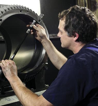
23 Direct Cable Connection Connecting cable, Series...K 23 3 ends 400 V 1), 6 ends 400/690 V 1) - Cable NSSHöu 3 winding end leads + PE 6 winding end leads + PE starting DOL Y / startup pole-changing Frame size Number of poles without temperature with temperature without temperature with temperature monitoring monitoring monitoring monitoring cable 1 cable 1 cable 1 cable strands 7 strands 7 strands 10 strands cross-section 1,5 mm 2 cross-section 1,5 mm 2 cross-section 1,5 mm 2 cross-section 1,5 mm max. 20 A max. 20 A max. 20 A max. 20 A outer dia approx. 13 mm outer dia approx.17,5 mm outer dia approx. 17,5 mm outer dia approx. 19,5mm cable 2nd additional 2 cables strands cable with 4 strands 4 strands each cross-section 4 mm 2 cross-section 1,5 mm 2 cross-section 4 mm 2 max. 36 A max. 20 A max. 36 A outer dia approx. 18 mm outer dia approx. 13 mm outer dia approx. 18 mm cable third additional 200 L1-2 4 strands cable with 4 strands 4 8 cross-section 10 mm 2 cross-section 1,5 mm 2 max. 65 A max. 20 A outer dia approx. 24 mm outer dia approx. 13 mm L2-2 1 cable 2 cables strands 4 strands each cross-section 16 mm 2 cross-section 16 mm 2 max. 87 A max. 87 A outer dia approx. 28 mm outer dia approx. 28 mm only for 500 V 1 cable 4 strands cross-section 16 mm 2 max. 87 A outer dia approx. 28 mm only for 690 V II Note: Cable included. Cable length 1.5 m. Special lengths on request. 1) Standard rating 50 Hz. Admissible currents must be taken into account for different specifications. Motor with direct cable connection

24 Bearing 24 II Bearing seals The motors are fitted with external radial or axial seals. Vertical construction types with upward-facing shaft can be fitted with a combined radial and axial seal on request. The seals prevent ingress of water along the shaft into the bearing housing. They have good abrasion resistance and thermal stability and are also resistant to mineral oils, saline solutions and diluted acids. Seals for media not listed above are available on request. Lubrication The bearings of motors up to frame size 280 have lifetime lubrication. The deep-groove ball bearings, which are sealed on both sides, are pre-packed with polyurea fiber grease by the bearing manufacturer. They are therefore maintenancefree for the time specified in the upper table on page 31. Relubrication and relubrication schedules Motors above frame size 315 are equipped with relubrication devices with grease distributors. Relubrication devices are also fitted to motors from frame size 225 that are equipped with roller bearings for heavy loads. Bearings with relubrication devices are packed with lithiumsaponified grease. The relubrication intervals are listed in the lower table on page 31. Lubrication intervals must be halved for vertical designs (V design). The relubrication must be implemented with the same grease type, i.e. grease with same saponification component and same consistency. ATB employs a lithiumsaponified anti-friction roller bearing grease with a drop point above 185 C (e.g. Esso Unirex N 3), see also motor label. The collecting chamber in the bearing cover is large enough to contain the used grease accumulating during normal service life. Flat grease nipples to DIN 3404 with thread size M10 x 1 are used for lubrication. Long-term dispenser It is possible to employ long-term dispensers for relubrication. They remain free from maintenance for max. 12 months, according to case of application. The explosion protection rating of the dispensers is II 2 G Ex ib IIC T6. Nominal service life In pure coupling operation, the theoretical service life is more than 50,000 operating hours. The max. admissible radial and axial loads are specified in the tables on pages 27 to 29. The calculations are based on a service life of the roller bearings of 20,000 hours. Drives with higher radial loads such as belt drives can be designed with roller bearings on request, see page 29. The minimum radial load specified must be maintained in order to ensure that the bearings roll correctly. For higher axial bearing loads such as occurring with helical gear, special solutions are available on request.
25 Bearing arrangement 25 IE1 Version Frame size Number of poles Drive-end bearing, all construction types Non-drive end series Standard reinforced (all construction types) CD (fixed bearings) bearing 2) floating bearings) 63 2, ZR ZR 71 2, 4, 6, ZR ZR 80 2, 4, 6, ZR ZR 90 2, 4, 6, ZR ZR 100 2, 4, 6, ZR C3 - NU ZR C , 4, 6, ZR C3 - NU ZR C , 4, 6, ZR C3 - NU ZR C , 4, 6, ZR C3 - NU ZR C , 4, 6, ZR C3 - NU ZR C , 4, 6, ZR C3 - NU ZR C , 4, 6, ZR C3 - NU ZR C , 4, 6, ZR C3 - NU ZR C , 4, 6, ZR C3 - NU ZR C C3 - NU C3 4, 6, C3 - NU C C3 - NU C3 4, 6, C3 - NU C3 Only construction type Construction type V1 1), V3 1) B3, B C B NU C4 4, 6, C B NU C C B NU C4 4, 6, C B NU C3 II Hinweis 1) for vertical operation only 2) Min. radial load required. See page 29. Non-drive end designed as fixed bearing. Bearing-type codes: example Z.WT.C = bearing size 2Z (2ZR) = non-rubbing double seal C3 = bearing clearance WT = Polyurea grease IE2, IE3 and MEPS Series Number of Drive-end bearing all Non-drive-end CD Y2,Y3,Y poles construction types reinforced bearings all construction Standard (fixed bearings) bearing 2) types (floating bearings) 80 2, 4, 6, Z 90 2, 4, 6, Z C Z C , 4, 6, Z C3 NU Z C , 4, 6, Z C3 NU Z C , 4, 6, Z C3 NU Z C , 4, 6, Z C3 NU Z C , 4, 6, Z C3 NU Z C , 4, 6, Z C3 NU Z C , 4, 6, Z C3 NU Z C , 4, 6, Z C3 NU Z C , 4, 6, Z C3 NU Z C C3 NU C3 4, 6, C3 NU C C3 NU C3 Series Number of Drive-end bearing all Non-drive-end CD XY poles construction types reinforced bearings all construction Standard (fixed bearings) bearing 2) types (floating bearings) 250S 2, 4, 6, Z C3 NU Z C3 250M 2, 4, 6, Z C3 NU Z C3 280S 2, 4, 6, Z C3 NU Z C3 280M C3 NU C3 4, 6, C3 NU C C3 NU C3 4, 6, C3 NU C3


")
26 Bearing 26 Bearing and seal arrangement d.e. n.d.e. Fixed bearing d.e. with radial shaft seal ring Standard for sizes 63 to 160 II d.e. n.d.e. Fixed bearing d.e. with axial shaft seal ring Standard for sizes from 180 d.e. n.d.e. Reinforced bearing d.e. (floating bearing; optional from size 100) with relubrication (optional from size 225) and combination seal (optional from size 80)
27 Permissible radial load, deep groove ball bearing 27 The distance of the point of application of force F R from the shaft collar should be no greater than the length of the shaft end. F R = max. radial axle load (e.g. overhung belt load + weight of belt pulley) [N] F = Belt pull [N] = 2 x K x M D M = Torque [Nm] = 9550 x P n P = Rated motor output [kw] n = Rated motor speed [rpm] D = Pulley diameter [m] K = Pre-tension factor, dependent on belt type and approximated as follows: K = 3 for normal flat belts without tensioning pulley K = 2 for normal flat belts with tensioning K = 2.2 for V-belts or special-purpose flat belts Specifications from size 400 only apply to horizontal shafts. Permissible radial bearing load F R [N] (deep groove bearing) Frame size Poles x 2 x 1 x Y Frame size Poles x 2 x 1 x 0 90 Y Y Y (Y) (Y) (Y) (Y) (Y) (Y) (Y) M XY (Y) M XY (Y) II
28 Bearing 28 Permissible axial load, deep groove ball bearing permissible axial bearing load F A [N]. 50 Hz II For construction types Frame 3000 rpm 1500 rpm 1000 rpm 750 rpm size Load to Load to Load to Load to N N N N N N N N IM B3, IM B5, IM B Y / Y / Y / Y / 132 (Y) (Y) (Y) (Y) (Y) (Y) (Y) (Y) (Y) N N N N N N N N IM V1, IM V5, IM V Y / Y / Y / Y /132 (Y) (Y) (Y) (Y) (Y) (Y) (Y) (Y) (Y) N N N N N N N N IM V3, IM V6, IM V Y / Y / Y / Y / 132 (Y) (Y) (Y) (Y) (Y) (Y) (Y) (Y) (Y)
29 Permissible radial bearing load, cylindrical roller bearing 29 Permissible radial bearing load F R [N] cylindrical roller bearing, min. load The distance of the point of application of force F R from the shaft collar should be no greater than the length of the shaft end. F R = max. radial axle load (e.g. overhung belt load + weight of belt pulley) [N] F = Belt load [N] = 2 x K x M D M = Torque [Nm] = 9550 x P n P = Rated motor output [kw] n = Rated motor speed [rpm] D = Pulley diameter [m] K = Pre-tension factor, dependent on belt type and approximated as follows: K = 3 for normal flat belts without tensioning pulley K = 2 for normal flat belts with tensioning K = 2.2 for V-belts or special-purpose flat belts Specifications from size 400 only apply to horizontal shafts. Minimum loading F R min at x 0 Due to their reinforced design, the bearings must be loaded with at least the forces indicated in the table. Even a test operation without a load can result in damage. Frame Number x 2 x 1 x 0 F R min size of poles at x o 90 Y Y Y (Y) (Y) (Y) (Y) (Y) (Y) (Y) (Y) L L , L3 6, (Y) L L L II
30 Bearings 30 Rotor weights for CD series,..(y2,y3,y) Rotor weights [kg] II Frame size 2p = 2 2p = 4 2p = 6 2p = 8 Typ-Y 3000 rpm 1500 rpm 1000 rpm 750 rpm 63 M1 1,5 1,8 M2 1,5 1,8 71 M1 1,4 1,5 M2 1,6 1,9 2,6 2,6 80 M1 2,2 2,7 3,7 3,7 M2 2,7 3,3 4,5 4,5 90 S 80M1 Y2,Y3,Y 3,0 3,7 4,5 4,5 L 80M2 Y2,Y3,Y 3,5 4,4 5,8 5,8 100 L 4,9 8,4 L1 90S Y2,Y3,Y 4,9 5,8 6,9 6,9 L2 90L Y2,Y3,Y 5,6 6,8 8,4 8,4 112 M 100L Y2,Y3,Y 6,5 9,9 12,1 12,1 132 S 112M Y2,Y3,Y 15,2 19,0 17,6 S1 112M Y2,Y3,Y 10,7 S2 12,4 132S2 Y2,Y3,Y 15,7 M 132S Y2,Y3,Y 16,7 17,3 16,0 132M Y2,Y3,Y 23,7 19,2 M1 132M Y2,Y3,Y 19,4 M2 132M2 Y2,Y3,Y 22,2 132M2 Y2,Y3,Y 24,5 160 M 31,9 38,1 Y2,Y3,Y 33,0 40,9 M1 Y2,Y3,Y 20,8 28,7 M2 Y2,Y3,Y 24,7 34,3 L 27,5 33,0 40,9 Y2 27,5 34,1 40,9 Y3, Y 27,5 37,3 46,2 42,7 180 M 38,5 48,5 Y2,Y3,Y 38,5 51,6 L 51,6 61,4 67,6 Y2 51,6 61,4 67,6 Y3, Y 55,9 61,4 67,6 200 L Y2,Y3,Y 74,0 95,9 L1 Y2,Y3,Y 50,4 51,1 L2 Y2,Y3,Y 61,4 84,4 225 S Y2,Y3,Y 93,7 104,3 M Y2,Y3,Y 76,0 108,0 122,0 122,0 250 M Y2,Y3,Y 99,0 136,0 156,0 176,0 280 S Y2,Y3,Y 109,0 144,0 148,0 179,0 M Y2,Y3,Y 122,0 163,0 171,0 207,0 315 S Y2,Y3,Y 155,0 215,0 269,0 250,0 M Y2,Y3,Y 181,0 261,0 300,0 290,0 L1 Y2,Y3,Y 208,0 293,0 360,0 338,0 L2 Y2,Y3,Y 260,0 465,0 491,0 452,0 L3 Y2,Y3,Y 340,0 465,0 576,0 576,0 355 M 582,5 629,0 L1 450,0 605,0 727, L2 486,0 656,0 879,0 880,0 L3 548,0 737,0 400 M 856,0 1006,0 1147,0 L 688,0 936,0 1107,0 1264,0 450 M 1066,0 1237,0 1399,0 L 1148,0 1340,0 1541,0
 Frame size Number of poles RT 40 C Frame size Number of poles RT 40 C 63 71 2 20000 h 63 71 2 20000 h 4, 6, 8 40000 h 4, 6, 8 40000 h 80 90 2 20000 h 80 90 2 15000 h 4, 6, 8 40000 h 4, 6, 8")
31 Lubrication, bearing monitoring 31 Maintenance-free service life with lifetime lubrication and coupling operation for horizontal mounting Motors with standard output Motors with increased output ( X,...W) Frame size Number of poles RT 40 C Frame size Number of poles RT 40 C h h 4, 6, h 4, 6, h h h 4, 6, h 4, 6, h h h 4, 6, h 4, 6, h h h 4, 6, h 4, 6, h II Relubrication intervals for horizontal construction type Motors with standard output Motors with increased output ( X,...W) Relubrication interval Relubrication interval rpm rpm Room temperature up to 1800 rpm up to 3600 rpm up to 1800 rpm up to 3600 rpm 40 C 5000 h 2500 h 5000 h 2500 h 50 C 2500 h 1000 h 2500 h 1000 h 60 C 2000 h 500 h - - Bearing monitoring For bearing status monitoring, the motors can be equipped with temperature sensors as well as shock pulse and vibration sensors. PT100 temperature sensors are mounted within the flameproof enclosure at the bearing points. Standard implementation uses 2 wire circuits, 3 or 4 wire circuits on request. The connection is implemented either in the main terminal box or in separate additional terminal boxes, which are attached to the main terminal box or to the motor housing, depending on the version. Wiring and boxes can be implemented based on explosion protection ratings Ex d, Ex e or Ex i. Vibration recorder and box Shock pulse nipples can be mounted externally at the end shields for the wear status monitoring above frame size 132. In this way, monitoring with mobile recording units is possible. For remote monitoring, use shock pulse or vibration sensors with hard wiring. The individual sensors are combined in a separate terminal box. The connection is implemented using explosion protection rating Ex ia IIC T4.
32 Bearing 32 Bearing eddy currents, insulated bearings, mechanical limit speeds II Bearing eddy currents, insulated bearings Through magnetic asymmetries on mains-powered motors, a voltage can occur along the shaft. This shaft voltage leads to transients between rotor and stator which flow through the roller bearings. If the voltage exceeds a peak value of 500 mv, the bearings may be damaged. This danger exists only for greater shaft heights. This effect can be amplified through operation with frequency inverter. The implementation of the inverter has a decisive influence in this case. Pulse-controlled AC inverters generate particularly high-frequency voltages and currents, depending on the clock frequency and pulse modulation. Output filters in the inverters minimize these effects. To avoid damaged bearings, an insulated bearing is therefore always installed on the non-drive end for inverter operation with motors from frame size 315. The operator must also provide for a large-area grounding of the motor housing to allow the currents circulating between inverter and stator to be diverted. High-voltage motors are provided with an insulated bearing on the non-drive end as standard. Mechanical speed limits If the motors operate above the rated speed, the limit values of the roller bearings, the strength of the rotating parts, critical rotor speeds and the tip speed of the fans need to be considered. The speeds limits indicated in the opposite table can make necessary measures such as special fans, special bearings or special balancing. The rotation speeds indicated for inverter operation in the operating data from page 58 are achieved with the standard motor. Mechanical speed limits Number size 63/ of poles 2 [rpm] [Hz] [rpm] [Hz] [rpm] [Hz] [rpm] [Hz]
33 Shaft ends, balancing, vibration amplitude, foundations 33 Shaft ends The motors normally have a free shaft end with dimensions conforming to EN From frame size 63, the shaft ends have an internal thread to DIN 332 type D. The feather-keys are designed to DIN 6885 Sheet 1. Motors with special shafts and/or a second shaft end are available on request at extra cost (does not apply to motors with axial fan and motors with attachments at the non-drive end, e.g. tachometer). Running smoothness of the shaft ends The running smoothness of the shaft ends corresponds to EN On request, the values can be reduced by 50% (extra-cost option). Balancing The motors are dynamically balanced with half feather-key. The balance quality corresponds according to DIN ISO 1940 minimum Q2.5. Special variants, balanced with a full feather-key, are an extra-cost option. In conformance with DIN ISO 8821, the shaft end faces of the motors are marked as follows: H = Half-feather key balancing F = Full-feather key balancing N = Balancing without feather key Vibration amplitude The mechanical vibrations according to EN correspond to Stage A in the standard version. In case of special requirements on the mechanical quiet running, lowvibration version can be supplied (reduced) to level B (extra cost option). II Vibration level with free suspension Frame size v eff [mm/s] Level A 1,6 2,2 2,8 Level B 0,7 1,1 1,8 Foundations Foundations must meet the requirements and ratings of DIN ISO They must be designed to be rigid or elastic according to the standard.
34 Bearing 34 Operating noise levels, cooling air quantity II Operating noise levels Noise levels are well below those specified in EN Noise measurements are performed according to EN ISO 3744 and EN according to class 2 in an anechoic room. The sound pressure level Lp and the sound power level L w in db(a) are indicated for the individual frame sizes in the operating datasheets. They apply for rated loads at 50 Hz, plus a tolerance of +3 db(a). For available variants of low-noise motors, see page 35. Cooling air quantity and permissible back pressure If the motors are to be operated above piping systems or under sound insulation cowls, the minimum cooling air quantities listed in the table below must be adhered to. The maximum back-pressures must not be exceeded to allow the self-ventilation to work properly. Cooling air quantity and permissible back pressure 3000 rpm 1500 rpm 1000 rpm 750 rpm Frame size Air volume Permissible Air Permissible Air Permissible Air Permissible pressure back pressure volume back pressure volume back pressure volume back pressure m 3 /s Pa m 3 /s Pa m 3 /s Pa m 3 /s Pa 71 0, , ,01 5 0, , , ,02 5 0, , , ,02 6 0, , , ,03 8 0, , , ,03 8 0, , , , , , , , , , , , , , , , , , , , , , , , , , , , , , , , , , , , , , , , , , , , ,00 45


35 Special-Purpose Motors Low-noise motors 35 Noise class 1 Standard version Radial-flow fans that are suited for rotation in both directions are employed for the standard type. The fans used are capable of conveying large volumes of air efficiently and at low noise levels. Noise class 2 axial-flow fans, series...a - low-noise For more exacting requirements, we recommend the lownoise variant with bi-directional axial-flow fan. These fans are available for 2-pole motors from frame size 112 and 4-pole motors from frame size 132. Through the aerodynamic design and the optimum angle of attack of the fan blades, a noise reduction for 2-pole motors of up to 10 db(a) is achieved compared with the standard version. Noise class 3 axial-flow fans in special-purpose design, series...ar - very low-noise For applications requiring extremely low noise levels, ATB has developed a range of exceptionally quiet, surfacecooled three-phase motors. Featuring a 2-pole design, these motors are approx. 12 db(a) quieter than their standard, radial-flow fan counterparts, and are quieter even than the low-noise axial-flow fan motors. For tables with the operating data for classes 1 to 3, see pages 58 and 60. Noise class 4 Water-cooled, series W - lowest-noise version The water-cooled ATB motors offer the following advantages: Reduced noise level due to omission of fan Prevention of air turbulence in dusty atmospheres (risk of dust explosion) Increased output compared to EN by a rating stage Mounting dimensions of IEC frame sizes are maintained Good heat removal without dissipation into surrounding air Potential for use of dissipated heat in heat exchangers The motor housing is a welded steel construction and is double-walled for water-cooling. To prevent corrosion, the water jacket is coated internally with several layers of synthetic material. The specified output values apply at a maximum water inlet temperature of 30 C. The maximum permissible suspended matter content is 30 mg/l. All motors are equipped with PTC thermistor temperature sensors for overload protection. Cooling water flow monitoring devices are therefore not required. For tables with operating data, see page 94. Frequency inverter operation All systems are suitable for inverter operation without any restrictions. II Radial-flow fan, bi-directional (noise class 1) Axial-flow fan, fan cowl with inlet opening, uni-directional (noise class 2 and 3] Water-cooled motors, (noise class 4)
36 Special-Purpose Motors 36 Low noise motors Sound pressure level II Noise class Standard version Series A Series AR Series...W (radial-flow fan) low-noise extremely low-noise low-noise version Temperature version version water-cooled class T4, (axial-flow fan) (axial-flow fan) Temperature class 50 Hz Temperature class Temperature class T4, T4, 50 Hz T4, 50 Hz 50 Hz Frame output Sound Sound Sound Sound Sound Sound Leistung Sound Sound size pressure output pressure output pressure output pressure output level level level level level level level level P 2 L p L W L p L W L p L W P 2 L p L W [kw] [db (A)] [db (A)] [db (A)] [db (A)] [db (A)] [db (A)] [kw] [db (A)] [db (A)] ns = 3000 rpm, 2p = M M-2Y S1-2 (Y) 5, S2-2 (Y) 7, M1-2 (Y) M2-2 (Y) , L-2 (Y) 18, M-2 (Y) L1-2 (Y) L2-2 (Y) M-2 (Y) M-2 (Y) S-2 (Y) M-2 (Y) S-2 (Y) M-2 (Y) L1-2 (Y) L2-2 (Y) L3-2 (Y) L1-2 (Y) L2-2 (Y) L3-2 (Y) ns = 1500 rpm, 2p = S-4 (Y) 5, M-4 (Y) 7, M-4 (Y) L-4 (Y) M-4 (Y) 18, L-4 (Y) L-4 (Y) S-4 (Y) M-4 (Y) M-4 (Y) S-4 (Y) M-4 (Y) S-4 (Y) M-4 (Y) L1-4 (Y) L2-4 (Y) L3-4 (Y) L1-4 (Y) L2-4 (Y) L3-4 (Y)

37 On-deck installation with shipping classification 37 Electrical machines installed on ships - especially on the top deck -, on oil rigs, in port facilities and in sewage treatment plants, must be able to withstand a high level of corrosive attack from the humid, saline atmosphere and occasional flooding. The same applies to fan motors in cooling systems and cooling towers. For these areas of application, motors have been developed by ATB in special corrosion-resistant implementation. In addition to the many features of the industrial motor series, such as long life; long maintenance intervals; high efficiency and performance low sound pollution of the environment, These motors incorporate a series of measures designed to protect the surface, the seals and the ventilation system from the effects of water and chemical. An anti-condensation heater can be fitted to the motors in order to prevent excessive condensation on the stator winding due to high temperature fluctuations and load changes (e.g. during intermittent use). This heater takes the form of heating strips attached to the winding heads. Anti-condensation heating is also possible through feeding of the stator coil with a reduced voltage. In addition, the windings can be protected by encapsulating them. This method can be used instead of an anti-condensation heater. II These special-purpose motors are certified for use in maritime applications by Germanischer Lloyd, Nippon Kaiji Kyobai, and Lloyd's Register. 1. Saltwater-resistant double seals 2. Corrosion-resistant shafts 3. Stainless-steel fastening screws 4. Saltwater-resistant multilayer special paintwork, also with zinc primer 5. Reinforced fan cowl with canopy and baffle plate to protect fan in high seas Special-purpose variants for on-deck installation Components Measures Protection type of motor and terminal box IP56 tested to DIN EN 60034, Part 5 Shafts The motor shafts are made from stainless steel. Shaft area seals For frame sizes up to 160, radial shaft seals to DIN 3760 are used D and N ends From frame size 180, motors are fitted with a combined sealing system consisting of a radial and an axial seal Fan cowl, canopy Frame sizes 71 to 160 have reinforced fan cowls, Material thickness 2 mm From frame size 180 fan cowls for all construction types with canopy and baffle plate material thickness <= 3mm Fan Fan in saltwater-resistant aluminum alloy or steel Fastening screws Stainless steel screws (A 2-70) used throughout Cable gland If supplied with cable gland, metal cable glands certified to DIN EN are used Paintwork Special paintwork with zinc primer

38 Special-Purpose Motors 38 Flexi mount motor The Flexi Mount Motor was designed to simplify warehouse stock keeping through the universal employment of one type of motor. Flange rings Additional carrying lugs above frame size 180 Protective canopy II The illustration shows how the flanges, the feet, the lugs and the protective cowl can be replaced. Thus all possible versions according to EN can be achieved from a basic motor. All these work operations are feasible without opening the flameproof chamber. No authorization from any authority is necessary for restarting operation. The conversion is reversible, so that one motor after another can be employed at different locations. Feet Available flanges Frame size FF flange dia. in mm 1) FT flange dia. in mm 1) FF flange dia. in mm 2) FT flange dia. in mm 2) O X O O O O O O O O O O O X O 0 O O O O 71 O O X O O O O O O O O O O O X O 0 O O O 80 O O O X O O O O O O O O O O O X O 0 O O 80 (Y) O O O X O O O O O O O O O X O O O O O 90 (Y) O O X O O O O O O O O O O X 0 O O 100 (Y) O O X O O O O O O O O X 0 O 112 (Y) O O X O O O O O O O X 0 O 132 (Y) O X O O O O O O O X O 160 (Y) O O X O O O O O X 180 (Y) O X O O O O O 200 (Y) O X O O O O 225 (Y) O X O O O 250 (Y) X O O 280 (Y) X O O 315 (Y) 0 X O 355 (Y) X X = Standard O = Special flange (extra cost option) All other versions require an intermediate ring (extra cost option). Note 1) new designation to EN ) old designation to DIN 42948

39 Built-on and built-in components, tachogenerator, reverse-running lock 39 ATB motors are designed to cover a wide range of applications. To meet the special requirements associated with each of these uses, a series of attachments has been developed. The standard attachment and use of brakes, tachogenerators and pulse generators, as well as reverse running locks, enables you to save costs. With the installation of one component, different combinations of special-purpose versions can be achieved. Attachments are available for frame sizes of 80 and higher. Explosion-proof equipment is connected to a reinforced fan cowl and either coupled to the motor shaft directly or by means of a backlash-free coupling. For IE2 or IE3 motor versions, the shaft length may be exceeded by the attachment for design reasons. For IE1 frame sizes 80 to 132 brakes and rotary encoders can be incorporated directly into the explosion-proof motor housing. Tachogenerator Actual-value sensors are employed for the electrical remote measurement, as well as regulation of the motor speed. These devices convert the input variable rotation speed into an analog or digital electric signal. Attached devices are connected using a separate terminal box. In case of motors with integrated sensor (...R series), the connection is implemented in the main terminal box. Reverse-running lock In the operation of conveying systems or pumps, the reverse-running lock prevents reverse-running after the shutdown of the motor. For the frame sizes 80 to 100, locking ball bearing can be used. This is especially recommended if this version should be combined with another attachment. Although the locking bodies are integrated into the bearings, the load-bearing capacity of the bearings is reduced only slightly compared to normal bearings. Since the locking bodies rub against the raceways, however, the maximum rotation speed is limited to 1500 rpm and a reduced bearing service life is to be expected. From frame size 90, the reverse-running lock can also be mounted onto a reinforced fan cowl directly on the extended motor shaft. This reverse-running lock is designed so that the clamping pieces lift off the stationary outer ring due to the centrifugal force if the minimum speed is maintained. No additional frictional forces or noise are therefore generated with this version. Reverse-running lock specifications Frame size Locking- Rated torque Useful life at bearing 1500 rpm DS type [Nm] [h] 80 ZZ 6204 L Y / 90 FC Y / 100 ZZ 6206 M II Frame size Reverse-running Rated torque Lift-off lock speed Type [Nm] [U/min] 90 FXM DX FXM DX FXM DX FXM DX FXM DX FXM DX FXM DX FXM DX on request 280 on request Motor with integrated incremental sensor
 or attached to a reinforced fan cowl on the non-drive side of the motor (..SVN or...s types). The electrical connection is made in a separate terminal compartment cast on to the brake.")
40 Special-Purpose Motors 40 Brake motors with attached brake II Our motors can be supplied with flameproof spring-loaded brakes in two variants. Attached as a flange version on the drive side (...SV type) or attached to a reinforced fan cowl on the non-drive side of the motor (..SVN or...s types). The electrical connection is made in a separate terminal compartment cast on to the brake. Type...SV and...svn series With flange motors of frame sizes 63 to 280 (e.g. B5 or B14 types), we recommend attaching this brake directly to the drive-side shaft end and the motor flange. The brake then provides the IEC connection dimensions for shaft and flange for attaching it to the machine (...SV type). For foot-mounted motors, the brake can be attached to a reinforced fan cowl on the non-drive side of the motor ( SVN type). This brake is available in the following versions: Frame size all pole configurations Frame size only 4, 6 or 8 poles or 2-poles S3 40% Frame size only 4, 6, 8 poles Terminal box Ex d 5 to 1200 Nm depending on frame size (for standard assignments, see page 87) 24 to 690 VAC 1~, 50/60 Hz, (for brake sizes 80 to 160 also 3~) 24 to 300 VDC Category 2 G / 2D / 2GD Protection type Ex d / Ex td A21 Protection group IIB / IIC Temperature class T3 / T4 / T5 maximum surface temperature T200 C / T135 C / T100 C Protection type IP66 Ambient temperature -20 to +40 C / -50 to +55 C thermal protection by means of thermo switch (in addition, PTC thermistor as an option) Manual ventilation (optional; not for 250/280) Micro switch (optional) Anti-condensation heater (optional) Special flanges or shafts on request Type CD...SV series
 110 to 400 VAC 1~, 50/60 Hz 12 up to 356VDC Category 2 G / 2D /")
 Micro switch (optional) Direct transmission mounting Motors with oil proof flanges can be fitted directly to transmission units.")
41 Brake motors with attached brake, direct transmission mounting 41 Type... S series This brake is always attached to a reinforced fan cowl on the non-drive side of the motor. Properties: Frame sizes 80 to 200 Terminal compartment Ex e 10 to 270 Nm depending on frame size (for standard assignment, see page 90) 110 to 400 VAC 1~, 50/60 Hz 12 up to 356VDC Category 2 G / 2D / 2GD Protection type Ex de / Ex td A21 Protection group IIC Temperature class T5 Maximum surface temperature T100 C Protection type IP67 Ambient temperature -20 C to +40 C Thermal protection by means of thermo switch Manual ventilation (optional) Micro switch (optional) Direct transmission mounting Motors with oil proof flanges can be fitted directly to transmission units. The shafts of these motors are sealed with radial seal rings to DIN The available flanges are listed in the table on page 38. The seal rings must be spray or mist lubricated. Motors up to frame size 450 have the fixed bearing on the drive side, in order to limit the thermal expansion of the rotor to the transmission. II Motor with attached transmission Motor with attached type... S brake
42 Special-Purpose Motors 42 Brake motors with integral brake Rectifier BD...B type series II Construction For frame sizes 80 to 132 motors, the brake is enclosed in a flameproof adapter housing mounted on the non-drive end of the motor to form a single unit. The ignition protection type is II 2G Ex d(e) IIB + H2 T4 or II 2D Ex td A21 IP65 T120 C. The system is completely maintenance-free for the lifespan of the brake linings. Connection The brake coil is energized by a silicon rectifier fitted inside the flameproof enclosure. The brake can be controlled from the AC or DC side. For operation from the DC side, a brake coil connection is fed into the terminal compartment. In addition, the motor is equipped with a protective resistor. If this layout is to be used for AC brake operation, a connection is not required in the terminal box. Instead, the connection shown in the circuit diagram must be established. On pole-changing and rectifier-supplied motors, the brake coil must be supplied from an external power source. Motor voltages Frame sizes 80 to 112: 230 V to 690 V Frame size 132: 400 V to 690 V Brake voltages For brake coil data, see page 92. Non-standard voltages are available at extra cost. Protective devices To protect the motor from excessive temperatures to DIN EN VDE 0165, three series-connected PTC thermistor temperature sensors are installed in the winding head (warmest point) of the three stator winding phases. In addition, each motor is equipped with a PTC thermistor temperature sensor in the brake coil and on the non-driveend shield. The temperature sensor are connected in series and protect the motor and brake from overloading or overheating. PTC thermistor Motor Brake Terminals BA1 and BA2 can be connected directly with the motor terminals to supply the brake. Please compare motor/brake voltage to determine whether connection must be made to U 1 /U 2 or to U 1 /V 1. Terminals BA3 and BA4 must be bridged. It is also possible to apply an external voltage to terminals BA1 and BA2. Please note the voltage rating on the rating plate. Terminals BA3 and BA4 must be bridged. For fast brake response (DC-side switch-off), the bridge between BA3 and BA4 can be replaced with a contact. The contact must switch at the same time as the brake voltage supply. For emergency release of the brake, e.g. to rotate the motor by hand, a DC voltage can be applied across terminals 1 and 4 (disconnect other wiring first and observe polarity). Voltage U = = U ~ x 0,45. Voltage U~ ; see brake voltage on the rating plate. Operating data For electrical motor ratings not specified in the operating data on page 88 (e.g. torque data), see the specifications for three-phase motors starting on page 58. Switching times, overtravel The table on the next page shows nominal brake response and recovery times and revolutions following power-off. The values were obtained in series testing.
43 43 Switching times, overtravel Frame Response DC Recovery Overtravel 1) size time switch- time AC DC AC off switch- switchswitch- off off off t 11 ~ t 11 = t 2 revolu- revolu- BD B [ms] [ms] [ms] tions tions 80M M S L L M S S M M S L L L M S M M M S L L M S M M M M S L L L M S M Note: 1) The overtravel of the motors was measured without additional centrifugal masses. Brake torque, wear values Through a combination of different coupling springs and brake disks, the brake torques can be adjusted (see table). Brake torque 1), wear values Frame size Rated torque Wear Brake disk M 2 Qr 0,1 Qr ges. new thickness BD B [Nm] [J] [J] [mm] x x10 6 6,9 10 2) 65x x10 6 6,9 11,5 13x x10 6 6, x x10 6 6, x x ) 100x x x x x x x x , x x ,4 46 2) 30x x , x x , x x , x x ,4 46 2) 30x x , x x , x x , x x , ) 65x x , x x ,15 Note: 1) Tolerance -20%/+40% at 1m/s friction speed 2) Standard torque The possible friction work Qr can be calculated according to the following formulae. Please take the wear limits from the table. J x n 2 Q r = x [J] 182,4 M v = M 2 + ( )* M L Q r [J] Q r 0,1 [J] Q r ges. [J] J [kgm 2 ] N [rpm] M 2 [Nm] M V [Nm] M L [Nm] AC switch-off t11 = Response times t2 = Recovery time M 2 M v [Nm] DC switch-off = Existing friction work per braking operation = friction work per 0.1 mm of wear = Friction work up to brake disk change = Moment of inertia = Rotation speed = Rated torque = Retardation torque = Load torque * Sign in brackets (-) applies in case of load braking downwards II

44 Three-phase AC Asynchronous Motors with Integrated Frequency Inverter 44 Compact drives CD...I type series II Compact drives with the explosion protection types II 2G Ex de IIC T4 or II 2D Ex td A21 IP65 T120 C consist of a flameproof ATB type CD motor with a type CEIGL flameproof frequency inverter attached. It is suitable for rotation-speed-controlled applications in explosion-hazard areas of zones 1 and 21. Frequency range The certification covers a frequency range from 2 to 100 Hz. Compact drives are therefore suitable for use in drive solutions up to 6000 rpm. Above 50 Hz, the drive is designed for operation in the field-weakening range, i.e. with constant power. Monitoring The thermal monitoring of motor and inverter is implemented through PTC thermistor temperature sensors. Optionally a certified thermistor tripping device, as well as an input contactor, can be installed in the inverter casing. A compact drive with galvanic separation can therefore provide the necessary switching functionality in case of a fault in an explosion-hazard area, without additional switching devices. Frequency inverter A full-featured LENZE 8200 vector frequency inverter is used to drive the motor with field-oriented vector control and a switching frequency of 4 khz., providing excellent running and control characteristics across the entire speed and torque range. The adaptation of the inverter to the motor with the recording of the motor parameters, as well as the base parameterization of the frequency inverter, is carried out during final inspection and testing. Control The compact drive is controlled using various exchangable frequency inverter modules according to user requirements. These modules are available for bus systems such as PROFIBUS-DP, interbus or CAN-Bus or as I/O modules for conventional control over analog set point value and ON/OFF contacts. Compact Drive Type CD 132 M-4 Specifications Ignition protection type Inverter casing certification flameproof enclosure/dust protection II 2G Ex de IIC T4 II 2D Ex td A21 IP65 T120 C PTB 08 ATEX 1111X Frame sizes 80 to 160 Supply voltage 380 to 500 V ±10 %, 50/60 Hz Range of power 0,55 bis 11 kw Maximum current 150 % I n for 60 s in 10 min Leakage current to PE > 3,5 ma (to EN 50178) Fixed installations required Fixed installations required double PE Output frequency 2 to 50/100 Hz Frequency resolution absolute 0,02 Hz Protective insulation of Safe isolation of PELV control circuits to EN EMC Compliance with requirements of EN /A11 EMC To limit power line interference, the inverter is equipped with a line reactor integrated into the flameproof casing as well as an EMC filter for grounded mains networks. The compact drive therefore meets the prerequisites of the specifications of the EMC Directive 2004/108/EC as well as the low-voltage Directive 2006/42/EC, i.e. conformity with DIN EN /A11 and compliance with the limit value class A according to DIN EN

45 45 Connections The connections of the supply voltage and control are implemented in an explosion-protected Ex e terminal compartment of the inverter casing. A manual terminal with keyboard and LC display is available for display of operating data, parameters and diagnostics. This key pad is connected to the frequency inverter via a plug to the explosion-protection Ex e terminal compartment. However, it is not explosion-proof and thus designed for short-term operation only. Compact motor terminal compartment Entries for mains supply cables Frame size Thread 2x M25x1,5 1x M32x1,5 type 1x M16x1,5 1x M25x1,5 1x M16x1,5 for cable outer dia. mm 6 11 Through the compact connection of a motor with frequency inverter, for employment in almost all explosion-hazard areas, with the following advantages for the user: - With certification according to ATEX 95, the motor can be used in zones 1 and 21 throughout Europe - with no additional national acceptance. - Simplified planning process - No additional control cabinet or switching system - Cost reduction through short feed to the motor. No shielded cables necessary. - Feed to the compact drive without EMC problems through the use of network and EMC filters on the motor. - Lower number of different part types and thus cost reduction through utilization of an inverter wide-voltage device for 400 V to 500 V mains voltage. - No version limitation since a standard ATB flameproof motor Ex d is used. - The version is available as a universal chemical industry motor (flexi mount motor). II For tables with operating data, see page 93. Mains V 50/60 Hz On-site operation* Ex de version Start/Stop/Reset/Setpoint Keypad for commissioning/service* Process control system Start/Stop/Setpoint Bus system Terminal compartement Ex e Converter zone Ex d Mains contactor* Line reactor PTC thermistor trippingdevice* EMC filter Frequency inverter Function module *optional Motor Ex d Functional diagram

46 High-Voltage Motors 46 CD...H type series II The high-voltage three-phase motors are explosion-proof with a flameproof enclosure, in accordance with DIN EN for Group IIC and temperature classes T3 to T6. Winding According to design, round-wire random-wound windings or conventional form-wound coils are employed. The thermal application meets insulation class B. Only in special cases, the class F limit is slightly exceeded. Design Series CD H to CD H Acceptance for category II 2G for use in zones 1 and 2 Acceptance for category II 2G for use in zones 21 and 22 Temperature classes T3 to T6 Power range from 160 to approx. 700 kw (for 1500 rpm) Rated voltage from 3 kv to 6.6 kv 50Hz for 2 to 8 poles, 60 Hz for 4 to 8 poles Self-cooling (IC411) with fans which are independent of the direction of rotation Low-noise design with axial fans which are dependent of the direction of rotation Anti-condensation heater Low temperature up to -55 C without heater Ambient temperatures of up to 60 C Altitude of installation above 1000 m m.s.l. - Installation of temperature sensors such as PT 100, PTC thermistors or KTY in winding and bearing for additional protection Customer-specific special-purpose versions High voltage motor Ex d IIC For tables with operating data, see page 95.
Technical Documentation
 Technical Documentation Three-Phase Explosion Proof Motors Flameproof Enclosure under license of Vision We get your ideas moving. We not only manufacture motors, we turn the ambitious ideas of our customers
BFG range BFGC range BFN range
 BFG range BFGC range BFN range LOW AND MEDIUM VOLTAGE MOTORS FOR HAZARDOUS AREAS EEx d EEx de EEx na - Flameproof Motors - Flameproof Motors With Increased Safety Terminal Box - Non Sparking Motors TABLE
High voltage flameproof induction motors The simplest solution for hazardous environments
 High voltage flameproof induction motors The simplest solution for hazardous environments We offer motors and generators, services and expertise that save energy and improve our customers processes over
ATEX LABELLING FOR MOTORS AND GEAR UNITS
 ATEX LABELLING FOR MOTORS AND GEAR UNITS EN ATEX INFORMATION GAS AND DUST COMPLETE DRIVE SOLUTIONS FROM A SINGLE SOURCE RELIABLE n Reliable products n Coordinated components n NORD's own development and
BFG range BFGC range BFN range
 BFG range BFGC range BFN range LOW AND MEDIUM VOLTAGE FOR HAZARDOUS AREAS EEx d EEx de EEx na - Flameproof Motors - Flameproof Motors With Increased Safety Terminal Box - Non Sparking Motors 1. MARKING
VALIADIS S.A. HELLENIC MOTORS
 Explosion proof motors MAK 56-250 (MAKe 63-250) series Groups IIB and IIC Ex db / Ex db e (EPL) executions Gb or Ex tb IIIC (EPL) Db II 2 G, II 2D, 2GD SAFETY INSTRUCTIONS Safety Instructions MAK and MAKe
Design specifications
 Design specifications Design To relevant standards: IEC, VDE, DIN, ISO, EN With squirrel-cage or slipring rotor Degree of protection IP 55 / IP 65 Cooling method IC511, suitable for both indoor and outdoor
Three-phase asynchronous motors with squirrel-cage rotor for potentially explosive atmospheres
 Three-phase asynchronous motors with squirrel-cage rotor for potentially explosive atmospheres VEM motors GmbH Table of contents Page Technical explications Motors in the increased safety type of protection
Explosion and flame-proof cast iron electric motors
 Explosion and flame-proof cast iron electric motors EEx-d, EEx-de, IIB, IIC II, 2G IP55 II, 2G&D IP66 T4, T5, T6 Frame size 56 to 160 3 phases Voltage 230/400 V 50Hz Voltage 265/460V 60Hz Types of mounting
Fans for ATEX EXPLOSIVE ATMOSPHERES
 Fans for ATEX EXPLOSIVE ATMOSPHERES An ATEX area is a mixture of air and inflammable gas, the vapour of an inflammable liquid, a fog of combustible liquid or combustible powder, which, if they catch fire,
Explosion and flame-proof single phase electric motors
 Explosion and flame-proof single phase electric motors EEx-d, EEx-de, IIB, IIC II, 2G IP55 II, 2G&D IP66 T4, T5, T6 Frame size 56 to 112 Single phase Voltage 230 50Hz Voltage 265 60Hz Types of mounting
Explosion proof electric motor For Fuel dispensing application. Main characteristic
 Ad-pe ed.2018/0 1 Explosion proof electric motor For Fuel dispensing application RAEL motori elettrici, since its inception in the late 60s, has assembled more than a million of explosion proof electric
Efficiency classes of single-speed three-phase, cage-induction motors
 Efficiency classes of single-speed three-phase, cage-induction motors New rules in the EU and Worldwide 30-40% of the generated electrical energy worldwide is consumed by electric motors Savings potential
Lenze ATEX-compliant gearboxes Gearboxes for use in potentially explosive atmospheres
 Lenze ATEX-compliant gearboxes Gearboxes for use in potentially explosive atmospheres ATEX for drive technology The ATEX directive, which has been in force since July 1, 2003, has been introduced in an
Low voltage asynchronous motors Motors for use in potentially explosive atmospheres
 Low voltage asynchronous motors Motors for use in potentially explosive atmospheres Type of protection Non sparking n Type of protection Flame-proof enclosure d/de Type of protection Protected by enclosure
CE Marking. Number of poles. Core Length. Frame size
 269 Electric Motors General Information CHALLENGE series three phase asynchronous AC electric motors, Are totally enclosed fan cooled (IC-411) squirrel caged type, With IP55 enclosure protection, Class
champion series motors
 Introducing A brand new series of Super Performers Data Sheet champion series motors FRAME SIZE 63-132M TEFC 3 Phase Squirrel Cage Induction Motors Siemens CHAMPION Series Cage Motors are suitable for
New Generation 1LE1/1PC1
 New Generation LE/PC /2 Orientation /2 Overview /3 Benefits /4 Application /4 Technical specifications /5 Selection and ordering data /7 More information /8 General Line motors with shorter delivery time
YFC. Limit switch. Ex d. 24 operating head types
 Ex d YFC Limit switch 24 operating head types - Group IIC - Zone 1, 2, 21, 22 - Aluminium alloy - Easy installation, wiring and maintenance - Durable and safe over time Fastening system Earth screw RAL735
EX-D ENCLOSURES AND DISTRIBUTIONS
 EX-D ENCLOSURES AND DISTRIBUTIONS Series GHG made of metal for gases of explosion group IIC To use MCBs, fuses, contactors etc. which give off arcs in potentially hazardous areas, they must be integrated
Solenoid Operator 0516 / 1216
 nass magnet GmbH Edition no. 2 Eckenerstraße 4-6 2007-01-10 D-30179 Hannover Rev.2 070110 Solenoid Operator 0516 / 1216 Operating Instructions NN 8220 126 and EC Declaration of Conformity Dear Customer!
Product Overview. Rotary Encoders for Potentially Explosive Atmospheres (ATEX)
") Product Overview Rotary Encoders for Potentially Explosive Atmospheres (ATEX) December 2013 Rotary encoders for use in potentially explosive areas Introduction There are many types of applications in industry
Product Overview Rotary Encoders for Potentially Explosive Atmospheres (ATEX) December 2013 Rotary encoders for use in potentially explosive areas Introduction There are many types of applications in industry
CONTENTS 1 GENERAL 2 STANDARDS. 3 TECHNICAL FEATURES 3.1 Basic Design Data 3.2 Standard Accessories 3.3 Tolerances
 CONTENTS 1 GENERAL 2 STANDARDS 3 TECHNICAL FEATURES 3.1 Basic Design Data 3.2 Standard Accessories 3.3 Tolerances 4 MOTOR DESIGN 4.1 Stator Casing 4.2 Stator Core with Winding 4.3 Stator Winding and Insulation
Technical Documentation
 Technical Documentation EX09EN ELECTRIC OTORS IN EXPLOSION - PROOF PROTECTION INCREASED SAFETY EExe FLAEPROOF ENCLOSURE EExd Vision We set your ideas in motion. We do not merely manufacture motors, but
Table of contents. Three-phase asynchronous motors DA
 be in motion be in motion AC Asynchronous Motors DA 100-280 Table of contents 1. Three-phase asynchronous motor DA 100-280... 3 1.1. General technical data... 3 1.2. Ratings definition for ventilated
Category 1 (zone 0) covers areas, where there is a permanent or long lasting occurrence
 covers areas, where there is a permanent or long lasting occurrence") Explosion proof fans General Systemair explosion proof fans have been developed to be used in effective supply and exhaust air systems allocated to category 2 (zone 1) and category 3 (zone 2) in explosion
Explosion proof fans General Systemair explosion proof fans have been developed to be used in effective supply and exhaust air systems allocated to category 2 (zone 1) and category 3 (zone 2) in explosion
CORE VALUES TECHNOLOGIES ESS-ESD PRODUCT CATALOGUE Enjoy the peace of mind ENGINE POWER SUPPLIERS AND EQUIPMENT HEAT
 TECHNOLOGIES ENGINE POWER SUPPLIERS AND EQUIPMENT HEAT Enjoy the peace of mind ESS-ESD PRODUCT CATALOGUE CORE VALUES PEACE OF MIND EFFICIENCY FAIRNESS RESPONSIBILITY CUSTOMER ORIENTATION GROWING DEVELOPED
Reg No: 1999/027771/07 ACCREDITED AND APPROVED TEST LABORATORY IN TERMS OF ARP 0108: REGULATORY REQUIREMENTS FOR EXPLOSION PROTECTED APPARATUS
 Government Approved Test Laboratory (Previously AIA) Reg No: 1999/027771/07 Equipment: Manufacturer: Type: ACCREDITED AND APPROVED TEST LABORATORY IN TERMS OF ARP 0108: REGULATORY REQUIREMENTS FOR EXPLOSION
Solenoid Operator 0513 / 1213
 nass magnet GmbH Run Nr. 5 Eckenerstraße 4-6 24.10.2006 D-30179 Hannover Rev. 5 061024 Solenoid Operator 0513 / 1213 Operating Instructions NN 8220 112 and EC Declaration of Conformity Dear Customer! In
IEC Range Three phase IEC low voltage motors - 56 to 355 frames. Single phase motors - 56 to 100 frames Capacitor Run Capacitor Start and Run
 CONTENTS Page 3 Selected Range of Motors RANGE INCLUDES.. Page 4 to 5 Standard Compliance Page 6 to 9 General Specifications Page 10 2 Pole - 3000 RPM Synchronous Speed 50 Hz Page 11 4 Pole - 1500 RPM
Asynchronous, Low Voltage, Squirrel Cage, Three Phase Electric Motors
 Asynchronous, Low Voltage, Squirrel Cage, Three Phase Electric Motors Series R2, Frame 63 355 Introduction KHM R2 series cast iron motors are totally enclosed fan cooled, 3 phase, and squirrel cage induction
A good connection. International approvals.
 E X - P L U G S A N D R E C E P T A C L E S 0 A to 25 A plugs and receptacles plastic version for zone, 2, 2 and 22 A good connection Providing electrical energy there, where it is most needed even in
Ex m Solenoid Operator Type 0519
 nass magnet GmbH Eckenerstrasse 4-6 D-30179 Hannover Doc. No. 113-720-0002 Revision No. 2 01.06.2015 Ex m Solenoid Operator Type 0519 Operating Instructions Dear Customer! To ensure the function and for
Three-phase motors for marine use
 Three-phase motors for marine use Contents Product description 11/2 Overview of technical data 11/7 Series K.../W4.. for Premium Efficiency IE3 11/8 Series K.../WE.. for High Efficiency IE2 11/12 Series
SERVICE AND EXPLOITATION INSTRUCTION MANUAL
 Edition: April 2007r. SERVICE AND EXPLOITATION INSTRUCTION MANUAL for three-phase, explosion-proof, increased safety, squirrel - cage induction motors: of frame size 56, 63, 71, 80, according to requirements
A6C A5C-B6C B5C B5H A6C A5C B6C B5C B5H. Model. Up to kw. Power. Up to V. Voltages. Model IP55. Frame Pole 2, 4, 6, 8 and 10
 A6C A5C-B6C B5C B5H Model Power Voltages Model IP55 A6C A5C B6C B5C B5H Up to 2.400 kw Up to 11.000 V LV A6C - B6C - A5C - B5C MV B5H Frame 71 560 Pole 2, 4, 6, 8 and 10 Cooling IC 411 ( IC 416 optional)
10 Load and Motor Switchgear
 10 Load and Motor gear Safety es 01941E00 Safety switches ensure the obligatory isolation of electrical power under condition of equipment cleaning, maintenance and repair. Other methods of isolation,
W22 Medium Voltage Motors TEFC - Severe Duty
 101 www.pamensky.com W22 Medium Voltage Motors TEFC - Severe Duty Standard Features Three-phase, 2, 4, 6 and 8 pole, 60Hz Voltage: 1200V, 2300V, 2400V, 3300V, 4000V, 4160V & 6600V Totally Enclosed Fan
1LG0 Low-voltage Motors
 Low-voltage motors up to 315kW Catalog D81.5.1 1LG Low-voltage Motors Answers for industry. 1 Table of Contents Overview 3 Motor standards 5 Mechanical design 6 Electrical design 1 Converter fed application
AESV / AESU / AESV-LA Series Squirrel Cage Induction Motor AESV1S / AESU1S / AESV1S-LA (IE1) STANDARD EFFICIENCY
 STANDARD EFFICIENCY") AESV / AESU / AESV-LA Series Squirrel Cage Induction Motor AESV1S / AESU1S / AESV1S-LA (IE1) STANDARD EFFICIENCY AESV2S / AESU2S / AESV2S-LA (IE2) HIGH EFFICIENCY AESV3S / AESU3S / AESV3S-LA (IE3) PREMIUM
AESV / AESU / AESV-LA Series Squirrel Cage Induction Motor AESV1S / AESU1S / AESV1S-LA (IE1) STANDARD EFFICIENCY AESV2S / AESU2S / AESV2S-LA (IE2) HIGH EFFICIENCY AESV3S / AESU3S / AESV3S-LA (IE3) PREMIUM
Technical Documentation
 Technical Documentation (B)OK 05 EN Drip - Pro Electric Motors type OK and (2.)B(P)OK Drip-Pro 3-Phase Induction Marine Motors Vision We set your ideas in motion. We do not merely manufacture motors, but
CONTENTS 1 GENERAL 2 STANDARDS. 3 TECHNICAL FEATURES 3.1 Basic Technical Data 3.2 Standard Accessories 3.3 Tolerances
 CONTENTS 1 GENERAL 2 STANDARDS 3 TECHNICAL FEATURES 3.1 Basic Technical Data 3.2 Standard Accessories 3.3 Tolerances 4 MOTOR DESIGN 4.1 Stator Casing 4.2 Stator Core with Winding 4.3 Stator Winding 4.4
From 16 June 2011, motors placed for the first-time on the market shall have a minimum efficiency class of IE2.
 INTRODUCTION New efficiency classes for the low-voltage three-phase motors (IE = International Efficiency). Along with the international discussion on energy efficiency a worldwide harmonized energy efficiency
Circulation pumps BFP-ATEX-T3/T4
 Circulation pumps BFP-ATEX-T3/T F ATEX - range of use: to zone 1 and zone 1 T3 to zone 1 and zone 1 T Low noise emission High vol. efficiency Optimum suction Gerotor principle Resistant to contamination
Operating Instructions
 Operating Instructions Terminal Box > 8150/1 > 8150/2 Contents 1 Contents 1 Contents...2 2 General Information...2 2.1 Manufacturer...2 2.2 Operating Instructions Information...2 3 Intended Use...2 4 Safety
Standardmotoren Standard motors
 Standardmotoren Standard motors Contents Product description 2/2 Overview of technical data 2/5 2 Series W4.R for Premium Efficiency IE3 2/6 Series WE.R for High Efficiency IE2 2/14 Series K2.R for Standard
Ex e, ia Junction boxes TNCN. Features
 TNCN Features The TNCN/TNCC range comprises many standard sizes of enclosure manufactured in 316L acid resistant stainless steel to give the maximum environmental protection. The main body is manufactured
0CV2. 0CV2 series dust explosion-proof three-phase. asynchronous motor INSTRUCTIONS. Siemens Standard Motors Ltd
 0CV2 0CV2 series dust explosion-proof three-phase asynchronous motor INSTRUCTIONS Siemens Standard Motors Ltd. 2017.02 1.0 Overview 0CV2 0CV2 series dust explosion-proof three-phase asynchronous motor
Apparatus which gives off arcs or sparks can be integrated in distributions at low cost using flameproof enclosures. Built-in electrical components
 E X - D D I S T R I B U T I O N S with metal EJ enclosures for gases in explosion group IIB Apparatus which gives off arcs or sparks can be integrated in distributions at low cost using flameproof enclosures.
ANNEX No 1. C 17/05/2006 SGA112B TERMINAL BOX ARRANGEMENT Ex e, Ex na &Ex td V (OPTION 2)
") ANNEX No 1 DRAWINGS Drawing No. Drawing Description Revision Date Ex e, na and td SGA100A General Arrangement for SGA 71 frame motor C 16/06/2006 SGA101A General Arrangement for SGA 80-132 frame motor
ANNEX No 1 DRAWINGS Drawing No. Drawing Description Revision Date Ex e, na and td SGA100A General Arrangement for SGA 71 frame motor C 16/06/2006 SGA101A General Arrangement for SGA 80-132 frame motor
INSTRUCTION MANUAL (ATEX / IECEx)
") INSTRUCTION MANUAL (ATEX / IECEx) BExBGL2D LED BEACON For use in Flammable Gas and Dust Atmospheres BExBGL2D 1) Warnings DO NOT OPEN WHEN AN EXPLOSIVE ATMOSPHERE IS PRESENT DO NOT OPEN WHEN ENERGIZED POTENTIAL
INSTRUCTION MANUAL (ATEX / IECEx) BExBGL2D LED BEACON For use in Flammable Gas and Dust Atmospheres BExBGL2D 1) Warnings DO NOT OPEN WHEN AN EXPLOSIVE ATMOSPHERE IS PRESENT DO NOT OPEN WHEN ENERGIZED POTENTIAL
Operating Instructions
 Operating Instructions Pendant Light Fitting > Contents 1 Contents 1 Contents...2 2 General Information...2 3 General Safety Instructions...3 4 Conformity to Standards...3 5 Intended Field of Application...3
Operating Instructions
 Operating Instructions Pendant Light Fitting > Contents 1 Contents 1 Contents...2 2 General Information...2 3 General Notes Regarding Safety...3 4 Intended Area of Application...4 5 Technical Data...5
MODEL INFORMATION CANNED MOTOR PUMP TYPE CAM HERMETIC
 MODEL INFORMATION CANNED MOTOR PUMP TYPE CAM HERMETIC ... 3... 4 3000 rpm 50 Hz / 3600 rpm 60 Hz... 4... 5... 7 Modular pump / motor systems... 7 Materials...........................................................
Ex-proof proportional relief valves Direct or pilot operated, without transducer - ATEX, IECEx, EAC or CULUS
 Table FX1-/E Replaces F6-5 /E E125-16 /E Ex-proof proportional relief valves Direct or pilot operated, without transducer - ATEX, IECEx, EAC or CULUS Valve main body Cartridge Mechanical pressure limiter
IP66 GSW GEAR BOX MOTOR SERIES
 IP66 GSW GEAR BOX MOTOR SERIES Three Phase Aluminium Gear Box Motors Australian Version October 2013 CONTENTS INTRODUCTION Pg 3 MATERIALS AND CONSTRUCTION Pg 3-4 SERIES OVERVIEW Pg 5 PERFORMANCE DATA Pg
MVSI. Technical features
 MVSI The MVSI series represents the line of reference products for manufacturer s of vibrating machines and plants operating in many industrial sectors and is made up of the largest range on the market,
High-efficiency three-phase induction motors ATEX GAS - Zones 1 & 2 ATEX DUST - Zones 21 & 22. Technical catalogue en
 High-efficiency three-phase induction motors ATEX GAS - Zones 1 & 2 ATEX DUST - Zones 21 & 22 Technical catalogue 4970 en - 2013.04/b High-efficiency three-phase induction motors ATEX GAS Zones 1 & 2
UZK12.261, UZO GENERAL DESCRIPTION 2. SHORT-FORM DATA 3. ORDER NUMBERS 4. MARKINGS BATTERY MODULE BATTERY MODULE 12V, 26AH 1/10.
 BATTERY MODULE Long Life Battery: 10 to 12 Years According to EUROBAT Small Mounting Footprint Easy Access to the Terminals and the Fuse Heavy Duty Fuse Holder and Spare Fuse Included 3 Year Warranty,
SWE SERIES (IE3) WONDER ELECTRIC MOTOR (S) PTE LTD. Energy Saving Low Noise Environmental Friendly IEC Dimension Low Vibration European Design
 WONDER ELECTRIC MOTOR (S) PTE LTD. Energy Saving Low Noise Environmental Friendly IEC Dimension Low Vibration European Design") RANGE OF PRODUCTS Three phase asynchronous squirrel-cage & slip ring induction motors Three phase asynchronous self-braking motors Hollow shaft rotor motors Cooling tower motors High motors, (IE2) (IE3)
RANGE OF PRODUCTS Three phase asynchronous squirrel-cage & slip ring induction motors Three phase asynchronous self-braking motors Hollow shaft rotor motors Cooling tower motors High motors, (IE2) (IE3)
TYPE 2 poles 4 poles 6 poles 8 poles 2 / 4 poles 4 / 8 poles 2 / 8 poles 4 / 16 poles
 BAH-BAHS series Overwiew MGM Electric Motors was established in 1950 as a brake motors manufacturer. MGM is today a world leading manufacturer of this line of products. MGM brake motors are designed and
: B3; B5; B14; B34; B35; V1
 ATT WE series (Eff1) are 3-phase TEFC Cast-Iron high efficiency general purpose induction motors, which are designed to meet or exceed the requirements for energy efficiency such as: European Eff1, Australia
Energy Saving Three Phase Motors
 e-drive Energy Saving Three Phase Motors IEC frames 56 to 400 Outputs 0.09 to 630 IE2 MEPS2006 Type: AHE Aluminium Motors Type: HE Cast-Iron Motors 1 When you need all the features of a premium quality
SIMOTICS GP Frame sizes 80 and 90
 Siemens AG 1 SIMOTICS GP General Purpose Motors - Frame sizes 8 and 9 Outstanding reliability made in Germany www.siemens.com/simotics-gp Brochure Edition January 1 Answers for industry. Siemens AG 1 SIMOTICS
Ordering information. When placing an order, specify motor type, size and product code according to the following example.
 Ordering information When placing an order, specify motor type, size and product code according to the following example. Example Motor type M3AA 112 MB Pole number 4 Mounting arrangement (IM-code) IM
EVZ Series (Small body) Explosion protected luminaire Operating Instructions
 Explosion protected luminaire Operating Instructions") EVZ Series (Small body) Explosion protected luminaire Operating Instructions Cooper Crouse-H i n d s Cooper E l ec t ron i c T ec h n ol og i es ( S h a n g h a i ) Co., L t d. No. 955 Shengli Road, East
EVZ Series (Small body) Explosion protected luminaire Operating Instructions Cooper Crouse-H i n d s Cooper E l ec t ron i c T ec h n ol og i es ( S h a n g h a i ) Co., L t d. No. 955 Shengli Road, East
FLSD (E) Atmospheres containing explosive GAS totally enclosed three-phase asynchronous motors General information
 Atmospheres containing explosive GAS totally enclosed three-phase asynchronous motors General information") (E) Atmospheres containing explosive GAS General information Flameproof totally enclosed three-phase asynchronous motors, FLSD (E) series, according to IEC 60034, 60038, 60072, 60079-0 and 60079-1, EN
(E) Atmospheres containing explosive GAS General information Flameproof totally enclosed three-phase asynchronous motors, FLSD (E) series, according to IEC 60034, 60038, 60072, 60079-0 and 60079-1, EN
Hazardous Location Enclosures INDEX. Hazardous Location Enclosures HAZ-2
 Hoffman s new ZonEX ATEX-certified enclosures can be used in Zone 1- and Zone 2-rated applications throughout the world. Our NEMA Type 9 enclosures are designed for use in Class II Division 1 and 2 locations
SINGLE PHASE TEFC CAGE MOTORS
 SINGLE PHASE TEFC CAGE MOTORS 2 SINGLE PHASE TEF CAGE MOTORS Mechanical protection: IP 54 Voltage: 220 V, 50 Hz Type Output power P N kw Rated speed n N min -1 Efficiency % Power factor cos Rated current
Technical Data. Dimensions
 Model Number Features 40 mm flush 4-wire DC ATEX-approval for zone 2 and zone 22 S Technical Data specifications Switching element function PNP NO/NC Rated operating distance s n 40 mm Installation flush
Junction Boxes & Enclosures JBES and ECES Series: 316L Stainless Steel Enclosures Increased Safety
 JBES Series Medium Voltage 11 kv ECES Series Compliance Data: ATEX - IEC: ATEX IEC CE Ex e II Ex ia IIC; Ex ib IIC T6 to T4 Ex td A21 T80 C to T130 C Ex de IIC; Ex demb IIC Operating Temperatures: -50
Petroleum industries are dealing with different hazardous materials starting from storing, processing and distributing the petroleum products These he
 FIRE SAFETY OF PETROLEUM INDUSTRIES By- Debapriya Biswas Additional Director General West Bengal Fire & Emergency Services Petroleum industries are dealing with different hazardous materials starting from
Squirrel Cage Induction Motors MA - A4 - BB - B4 - B5 SERIES SIZES. MarelliMotori ASI.CT.033.2
 Marine Motors Three Phase Squirrel Cage Induction Motors MA - A4 - BB - B4 - B5 SERIES 63-400 SIZES MarelliMotori ASI.CT.033.2 CONTENTS Page STANDARDS 5 ESSENTIAL AND NON-ESSENTIAL SERVICE 5 CLASSIFICATION
Protection against mechanical impacts IK 08 according to IEC 68, EN Insulation class Class F (155 C), class H (180 C) on request.
, class H (180 C) on request.") MVSI The MVSI series represents the line of reference products for manufacturer s of vibrating machines and plants operating in many industrial sectors and is made up of the largest range on the market,
MVSI The MVSI series represents the line of reference products for manufacturer s of vibrating machines and plants operating in many industrial sectors and is made up of the largest range on the market,
INSTRUCTION MANUAL (ATEX / IECEx)
") INSTRUCTION MANUAL (ATEX / IECEx) BExBG10D-P and BExBG15D-P Flameproof Xenon Beacons For use in Flammable Gas and Dust Atmospheres BExBG10D-P / BExBG15D-P 1) Warnings DO NOT OPEN WHEN AN EXPLOSIVE ATMOSPHERE
INSTRUCTION MANUAL (ATEX / IECEx) BExBG10D-P and BExBG15D-P Flameproof Xenon Beacons For use in Flammable Gas and Dust Atmospheres BExBG10D-P / BExBG15D-P 1) Warnings DO NOT OPEN WHEN AN EXPLOSIVE ATMOSPHERE
Flameproof Enclosures
 Flameproof Enclosures The range comprises many standard sizes of enclosures manufactured in stainless steel 316L and/or in painted carbon steel. The enclosures allow for utilization of standard electrical
Type SIMOPRIME A4, up to 24 kv, Air-Insulated Medium-Voltage Switchgear
 Circuit-Breaker www.siemens.com/energy Switchgear Type SIMOPRIME A4, up to 24 kv, Air-Insulated Medium-Voltage Switchgear s Technology Circuit-Breaker Switchgear Type SIMOPRIME, up to 17.5 kv, Air-Insulated
Operating Instructions
 Operating Instructions N R 468 en 02.11 Explosion proof three phase motors with squirrel cage for low voltage, with antifriction bearings Protection type Increased Safety e (acc. to Directive 94/9/EC,
Explosion-proof motors
 /2 Orientation /2 Overview /3 Benefits /3 Application /3 Technical specifications /5 Selection and ordering data /7 More information /12 Self-ventilated motors in Zone 1 with type of protection "e" Aluminium
Three-phase asynchronous motors
 Three-phase asynchronous motors for low voltage with squirrel-cage rotor Product specification Series K11R, K21R and K22R Introduction Standards and regulations Progressive correspondence between output
System Electropneumatic Converters (Proportional Valves) Electronic Process Controllers Signal Converters
 Electronic Process Controllers Signal Converters") System 6000 Electropneumatic Converters (Proportional Valves) Electronic Process Controllers Signal Converters Edition April 2018 Information Sheet T 6000 EN Electropneumatic Converters i/p converters
System 6000 Electropneumatic Converters (Proportional Valves) Electronic Process Controllers Signal Converters Edition April 2018 Information Sheet T 6000 EN Electropneumatic Converters i/p converters
How do you take the first step towards an energy efficient future?
 How do you take the first step towards an energy efficient future? Low-voltage induction motors according to the new standard and new classes Answers for industry. EU Directive 2005/32/EC and IEC 60034-30
Proportional pressure reducing valves type DHRZO and DHRZA standard and ex-proof version, direct operated, ISO 4401 size 06
 www.atos.com Table TF040-2/E Proportional pressure reducing valves type DHRZO and DHRZA standard and ex-proof version, direct operated, ISO 4401 size 06 A B DHRZO-A-012/25 A B DHRZA-A-010/25 DHRZ* are
GOVERNMENT APPROVED TEST LABORATORY IN TERMS OF ARP 0108: REGULATORY REQUIREMENTS FOR EXPLOSION PROTECTED APPARATUS
 Reg No: 1999/027771/07 (Pty) Ltd 7 Spanner Rd / PO Box 467 Olifantsfontein 1665 Tel: +27 (11) 316 4601 Fax: +27 (11) 316 5670 E-mail: admin-mgr@explolabs.co.za GOVERNMENT APPROVED TEST LABORATORY IN TERMS
Light Fittings for Fluorescent Lamps Series EXLUX 6000 / 6400
 > As pendant light fitting or side entry lamp > Version with 1 or 2 lamps: 18 W, 36 W and 58 W > Central locking > All-pole disconnection by means of an N/C switch when the lamp is opened > End of life
Load disconnect switch Series 8146/5-V11
 www.stahl.de Load disconnect switch > Motor switching capacity AC-3 and AC-23 acc. to DIN VDE 0660 part 107 IEC/EN 60947-3 > Isolating characteristics acc. to IEC/EN 60947-3 > Positive opening operation
NEMA & IEC Product Features and Benefits
 NEMA & IEC Product Features and Benefits BEAUTY BENEATH THE SURFACE. Looking at a Techtop electric motor, it would be understandable if you thought it was just another NEMA or IEC squirrel-cage induction
Centrifugal fan with highly efficient EC drive motor
 Centrifugal fan with highly efficient EC drive motor simple and safe application and installation 2 Why HLU? 90 years of experience in the plastics processing market More than 10.000 m² production in Germany
MVSI-TS. Split covers. Technical features
 MVSI-TS Split covers The MVSI-TS series, obtained directly from the MVSI series, is characterized by the split weight covers. The weight cover is divided into two halves that can be removed in a radial
Table of contents. Three-phase asynchronous motors DA
 Table of contents 1. Three-phase asynchronous motor DA 100-280... 5 1.1. General technical data... 5 1.2. General safety instructions... 6 1.3. Definitions of power ratings... 7 1.3.1. Definitions of power
EU MEPS for low voltage electric motors
 EU MEPS for low voltage electric motors EU MEPS in brief EU MEPS (European Minimum Energy Performance Standard) sets mandatory minimum efficiency levels for electric motors introduced into the European
SECTION MOTOR REQUIREMENTS for HVAC
 PART 1 GENERAL 1.1 SECTION INCLUDES A. Single-phase electric motors B. Three-phase electric motors 1.2 REFERENCES SECTION 23 05 13 MOTOR REQUIREMENTS for HVAC A. ABMA 9 - Load Ratings and Fatigue Life
SERIES 54 Inductive Proximity Sensor
 SENSOR FEATURES > 2-wire DC sensor with minimum off-state current > ATEX-approval for zone 2 and zone 22 > High temp, UV, salt water resistant > Rugged metal base > IP66/67/69K > High impact protection
INSTALLATION AND SERVICE INSTRUCTIONS FOR 2000 SERIES FLAMEPROOF XENON AND FLUORESCENT BEACONS
 INSTALLATION AND SERVICE INSTRUCTIONS FOR 2000 SERIES FLAMEPROOF XENON AND FLUORESCENT BEACONS Address all communications and shipments to: FEDERAL SIGNAL CORPORATION Industrial Systems Group 2645 Federal
ODP SERIES PREMIUM INDUSTRIAL OPEN DRIP PROOF MOTORS C280M to C355LB Frame. Australian Version October 2013
 ODP SERIES PREMIUM INDUSTRIAL OPEN DRIP PROOF MOTORS C280M to C355LB Frame Australian Version October 2013 ODP SERIES (OPEN DRIP PROOF) PREMIUM INDUSTRIAL OPEN DRIP PROOF MOTORS, C280M TO C355LB FRAME
UZK24.071, UZO GENERAL DESCRIPTION 2. SHORT-FORM DATA 3. ORDER NUMBERS 4. MARKINGS
 BATTERY MODULE 24V, 7Ah Battery Capacity (2x 12V Batteries in Series) Small Mounting Footprint 2m Power Leads Included PT1000 Sensor for Battery Module Temperature Included Includes a Center-tap Terminal
Small centrifugal fans made of plastic
 Small centrifugal fans made of plastic durable application-optimised wide range of variants 2 Small centrifugal fans made of plastic Index Small centrifugal fans made of plastic HF R 75-16 D and HF R 110-18
List Price. Mult. Sym. C Dim. Single Phase
 Single and Three Phase, Foot Mounted Explosion Proof 1/4 thru 300 48 thru 449TY Applications: Ideal for use where hazardous fumes or dust may be present. Features: U.L. and CSA approved for Class I, Group
1/4 thru 300 Hp NEMA 48 thru 449TY. List Price. Mult. Sym. C Dim. Single Phase
 Single and Three Phase, Foot Mounted Explosion Proof 1/4 thru 300 48 thru 449TY Applications: Ideal for use where hazardous fumes or dust may be present. Features: U.L. and CSA approved for Class I, Group
Turbogenerators. With Top Performance for Steam and Gas Applications. Specifically tailored 4-pole Synchronous Turbogenerators
 Turbogenerators With Top Performance for Steam and Gas Applications Specifically tailored 4-pole Synchronous Turbogenerators siemens.com / automation 2 Top Performance Turbogenerators for Steam and Gas