NFPA 285 TEST REPORT. Report No.: H Test Date: June 1, Rendered to: ARCONIC ARCHITECTURAL PRODUCTS Eastman, Georgia
|
|
|
- Thomas Daniels
- 5 years ago
- Views:
Transcription
1 NFPA 285 TEST REPORT Report No.: H Test Date: June 1, 2017 Rendered to: ARCONIC ARCHITECTURAL PRODUCTS Eastman, Georgia WALL SYSTEM: Exterior Non-loadbearing Wall Assembly COMBUSTIBLE COMPONENTS: 6 mm Reynobond ACM with FR core Panel System attached to Technoform Hybrid Thermal Spacers with 4 in. thick Rmax TSX-8500 Insulation and Grace Perm-A-Barrier Vapor Permeable Air Barrier This report contains in its entirety: Cover Page: 1 page Report Body: 10 pages Graphical Data: 7 pages Numerical Data: 21 pages Photographs: 8 pages Drawings: 10 pages
2 Report Date: 07/24/2018 Page 1 of Report Issued To: Arconic Architectural Products 50 Industrial Blvd. Eastman, Georgia Test Laboratory: Architectural Testing, Inc., an Intertek company ( Intertek-ATI ) York, Pennsylvania Introduction: [Section 1.3.1, NFPA 285] The NFPA 285 test apparatus is used to evaluate the fire propagation characteristics of exterior non-load-bearing wall assemblies and panels used as components of curtain wall assemblies that are constructed using combustible materials or that incorporate combustible components within the wall assemblies as specified in the following: A. The ability of the wall assembly to resist flame propagation over the exterior face of the wall assembly. B. The ability of the wall assembly to resist vertical flame propagation within the combustible core or within other combustible components from one story to the next. C. The ability of the wall assembly to resist vertical flame propagation over the interior surface of the wall assembly from one story to the next. D. The ability of the wall assembly to resist lateral flame propagation from the compartment of fire origin to adjacent compartments or spaces. 4.0 Project Summary: 4.1 Wall System: Exterior Non-loadbearing Wall Assembly 4.2 Combustible Components: 6 mm Reynobond ACM RB240FR with FR core 8. Rout and Return Rainscreen Panel System attached to Technoform Hybrid Thermal Spacers with 4 in. thick Rmax TSX-8500 Insulation and Grace Perm-A-Barrier Vapor Permeable Air Barrier 4.3 Compliance Statement: Results obtained are tested values and were secured by using the designated test method(s). The specimen(s) were tested and evaluated against the requirements of the standard. A summary of the results is listed in the Test Results section and the complete graphical test data is included in Appendix A of this report. 4.4 Test Date: 06/01/ Test Location: Intertek-ATI test facility in York, Pennsylvania. 4.6 Test Sample Source: The components of the test specimen were provided by the client except for the core wall components that were selected by the client were then assembled by Intertek-ATI personnel.
3 Report Date: 07/24/2018 Page 2 of Project Summary: (Continued) 4.7 Test Method(s), Practices and/or Classifications: NFPA Standard Fire Test Method for Evaluation of Fire Propagation Characteristics of Exterior Non-Load- Bearing Wall Assemblies Containing Combustible Components, List of Official Observers: Name Thomas Rogers William Green Tim Feltman Scott Gingrich Mark Dluzeski Company Arconic Architectural Products Technoform NA, Inc. Intertek-ATI Intertek-ATI Intertek-ATI 5.0 Calibration Information: The apparatus is considered to be under calibrated conditions when the time average temperatures and the time average heat flux readings obtained for a calibration wall match the requirements of Table of NFPA 285. Calibration was performed on February 15, Table 1 shows the average burner flow and heat flux. Table 2 shows the time average temperatures obtained during the calibration test. The values are within the allowable ranges as specified in Table (±10%). Table 1 Average Burner Output Information Time Interval (min) Room Burner (SCFM) Window Burner (SCFM) 2 FT Flux (W/cm 2 ) 3 FT Flux (W/cm 2 ) 4 FT Flux (W/cm 2 ) 0:00-5: :00-10: :00-15: :00-20: :00-25: :00-30:
4 Report Date: 07/24/2018 Page 3 of Calibration Information: (Continued) Table 2 Average Time Temperature Values for Calibration Location Time (min) Burn Room ( F) Int. Wall ( F) 1FT ( F) 2FT ( F) 3FT ( F) 4FT ( F) 5FT ( F) 6FT ( F) 0:00-5: :00-10: :00-15: :00-20: :00-25: :00-30: Test Specimen Description: Interior Cladding: The interior surface of the wall was clad with National Gypsum Gold Bond Fire Shield 5/8 in. thick Type X gypsum board meeting ASTM C1396 and fastened to the core wall with #6 x 1-1/4 in. long flat head self-drilling screws with a nominal spacing of 8 inches on the perimeter and 12 inches in the field. Drywall orientation on the burn floor consisted of four pieces of Type X gypsum fastened to the core wall, parallel with the studs. Drywall orientation on the second floor consisted of vertically oriented sheets with the long dimension running parallel with the studs. Drywall orientation for the gaps above the top support angle and below the bottom support angle consisted of drywall that was oriented with the long dimension running perpendicular with the steel studs. All joints were taped with USG Sheetrock paper joint tape, and spackled with USG Sheetrock Joint Compound. Core Wall: The core wall was 17 feet 6 inches tall and 13 feet 4 inches in width. The wall framing consisted of 6 inches deep, 18 gauge galvanized steel studs and galvanized steel track spaced 16 inches on center. The studs were connected to the track with #6 x 1/2 inch long self-drilling screws. Horizontal 16 gauge x 1-1/2 inches wide CRC galvanized steel bracing was fit into the knockouts of the studs and fastened to the studs every 4 feet above the window opening using ClarkDietrich FastBridge FB43 clips. The clips were attached to the studs with two #6 x 1/2 inch long button head self-drilling screws. Johns Manville MinWool Safing pieces with a nominal density of 4.0 lbs./cu. ft. were installed per the manufacturer s installation instructions to fit into each stud cavity placed at the floor line. The safing length dimensions were no less than the apparatus floor slab thickness measuring 8 inches. On completion of the test assembly the perimeter of the assembly was covered with inch thick aluminum trim coil.
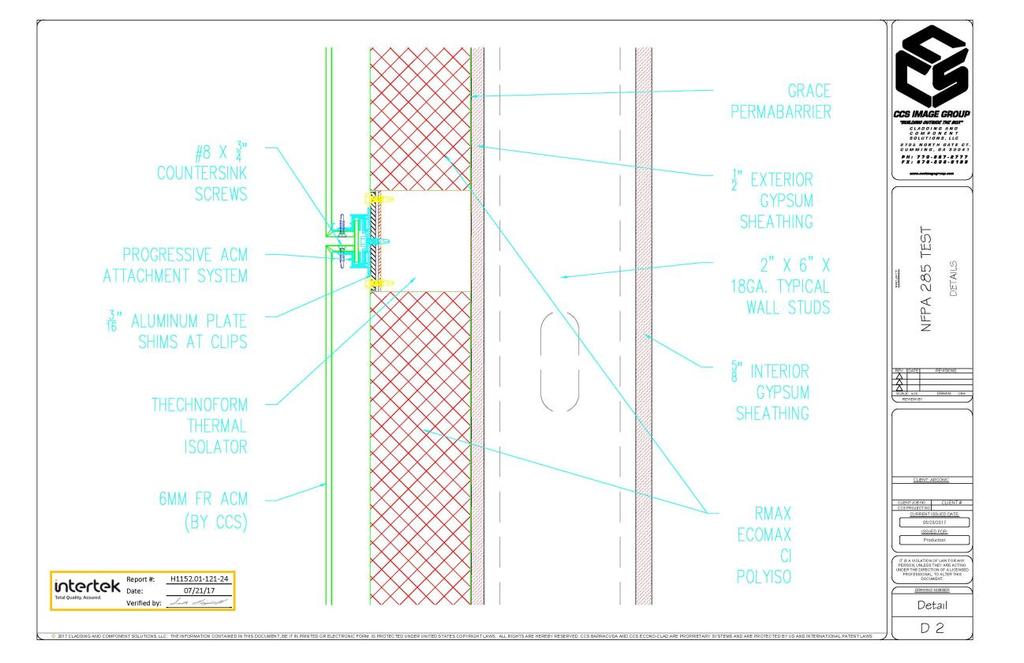
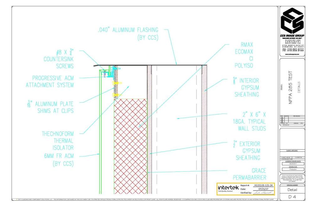
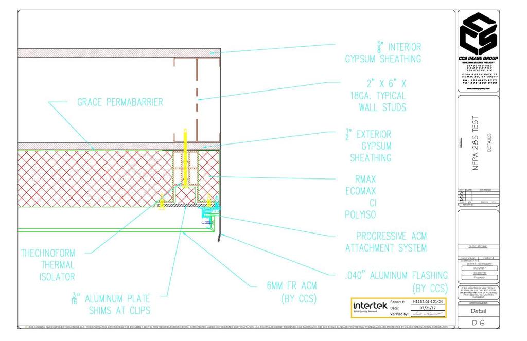
5 Report Date: 07/24/2018 Page 4 of Test Specimen Description: (Continued) Window Opening: A 78 inch wide x 30 inch tall window opening was constructed with 18 gauge galvanized steel track centered on the vertical centerline of the wall assembly. The finished sill of the opening was 30 inches above the first story floor line. The steel track sections were mechanically fastened with #6 x 1/2 inch long self-drilling pan head fasteners at each corner. Upon completion of the exterior cladding, the window was flashed with inch thick aluminum flashing. Exterior Sheathing: 1/2 inch thick USG Securock Brand Glass-Mat sheathing panels meeting ASTM C1177 were placed horizontally across the exterior surface of the assembly. Sheathing vertical joints were offset 16 inches at each row. The gypsum board was fastened to the framing members with #6 x 1-1/4 inch bugle head fasteners spaced every 8 inches along the perimeter and every 12 inches in the field. Air/Water Barrier: Upon completion of the installation of the exterior sheathing, Grace Perm-A-Barrier Primer Plus was applied horizontally over the full exterior surface of the assembly in accordance with the manufacturer s recommended application rate of square feet per gallon. Once applied, Grace Perm-A-Barrier VPS was applied vertically over the full exterior surface of the assembly. The overlap of the horizontal rows was 2 inches. Excess material within the window opening was cut and adhered to the window opening framing with the excess then trimmed off. Exterior Insulation: Upon completion of the Grace Perm-A-Barrier 4 in. thick Rmax TSX-8500 insulation with dimensions of 48 inches wide x 96 inches long was placed over the full exterior surface of the assembly. The insulation boards were placed vertically on the core wall with the longest dimension running parallel with the steel studs. The insulation was retained against the wall using 5 inches long Firestone W56RAC inches long heavy duty fasteners with 3 in. diameter firestone insulation washers nominally every 4 feet on each vertical framing member. The insulation joints were then covered with Nashua 324A aluminum foil tape.
6 Report Date: 07/24/2018 Page 5 of Test Specimen Description: (Continued) Exterior Cladding: After the installation of the insulation, 3-3/4 inch thick Technoform TE Hybrid Thermal Spacers were attached to each vertical framing member with two 1/4-20 x 4 inch long hex washer head (HWH) #4 point Elco Dril-Flex structural self-drilling fasteners per thermal spacer at pre-determined locations (reference drawings in Appendix D) inch thick 6063-T6 x 4 inches long aluminum extrusions were placed over the thermal spacers before fastening. The previously installed insulation was cut way to allow the installation of the extrusions. The thermal spacers were spaced vertically at predetermined locations with regard to the exterior panel installation (reference drawings in Appendix D). Once the thermal spacers and insulation were installed, 6 mm thick Reynobond ACM panels RB240FR with FR core 8 were then installed over the full exterior surface. The panel installation began with a continuous aluminum extrusion located at the assembly sill. The starter extrusion was fastened to the each of the Technoform Hybrid Thermal Spacers at the sill with #12-14 x 1-1/2 inch long Dril-Flex structural self-drilling fasteners every 16 inches. The 6mm Reynobond ACM with FR core panels were installed, using two 4 inches wide extruded aluminum H -clips. The first row of panels were placed on the aluminum extrusion and were attached to the Technoform Hybrid Thermal Spacers using two #12-14 x 1-1/2 inch long HWH #3 point ELCO Dril-Flex Structural self-drilling fasteners through the H-clips. The 6 mm thick Reynobond ACM RB160FR with FR Core splines were placed in the vertical and horizontal panel joints. The panel installation continued by placing the next row panels into the H-clips on the panel row below. The panel system utilized a nominal 1/2 inch reveal at the panel joints. The first panel row above the window opening header was placed on a starter extrusion and fastened to the Technoform Hybrid Thermal Spacer clips at the window opening header. Panel installation continued vertically to the assembly header/parapet. Vertical joint locations were located on the assembly centerline and at the vertical planes of the window opening jambs. Horizontal panel joints were located 36 inches, 72 inches, and 108 inches above the window opening header. 7.0 Instrumentation and Test Procedure: 7.1 Instrumentation: The wall assembly was instrumented with thermocouples in accordance with Figure 6.1 of the NFPA 285 test method. Thermocouples in the burn room were 18-gauge Type K TCs and 20-gauge Type K TCs were used on exterior façade and stud cavity air space. The window burner was positioned in the center of the opening and 3 in. from the exterior face of the wall assembly. The position of the window burner was determined by calibration of the ISMA on February 15, Test Procedure: Testing was performed on June 01, 2017, in accordance with the NFPA 285 test method. Ambient conditions were 76 F and 37% relative humidity. An anemometer was used to verify airflow across test assembly was less than 4 ft./s as specified in the test method. Video recording, digital photographs, visual observations, and data collection were performed prior, during, and after testing was completed. Temperature data was recorded every 15 seconds.
7 Report Date: 07/24/2018 Page 6 of Test Results: The test was started at 04:05 PM with the burners on for 30 minutes. The burners were turned off and the specimen was allowed to burn for an additional 10 minutes after the test. All observations are recorded in the following table. Table 3 Test Observations Time (min:sec) Observations 00:00 Ignition of the room burner. 01:35 Ignition of the interior first story gypsum board. 02:00 Paint on the panels above the window opening chars and burns. 05:00 Ignition of the window burner. 06:08 Panels above window header begins to swell. 12:00 Panel paint at the 4 foot horizontal line begins to char. 16:00 Window header fallout. 17:00 Window header ignition. 17:22 Core falls from panel above the window opening. 20:00 Panel opens above the window header. 22:00 Surface burning up to 2 feet above the window opening header. 23:26 Surface burning up to 3 feet above the window opening header. 24:56 Panel above the window header outer skin melts. 25:46 Surface burning up to 4 feet above the window opening header. 30:00 The burners were extinguished. 40:00 Test observations stopped.
8 Report Date: 07/24/2018 Page 7 of Test Results: (Continued) Table 4 Test Requirements Test Requirements Test Observations Pass/Fail Flames did not reach 10 ft. above the Flames did not reach 10 ft. above the PASS window opening header. window opening header. Flames did not reach a lateral distance of Flames did not reach a lateral distance PASS 5 ft. from the vertical centerline. of 5 ft. from the vertical centerline. Flames did not propagate beyond the Flames did not propagate beyond the PASS limits of the first story test room. limits of the first story test room. No visible flaming in the second story No visible flaming in the second story PASS test room test room. TC s 11 and (1000 F limit) TC s 11, and did not exceed their 1000 F test limit. PASS TC s 18-19, 28, and (1000 F limit) TC s 18-19, 28, and did not PASS exceed the 1000 F limit TC s (750 F above ambient) TC s did not exceed 750 F PASS above their ambient temperatures. TC s (500 F above ambient) TC s did not exceed 500 F above their ambient temperatures. PASS
9 Report Date: 07/24/2018 Page 8 of Test Results: (Continued) Description of Extent of Damage: Interior Cladding: The interior gypsum was still intact after the separation of the assembly from the test fixture. However, the area of the first floor (Fire Room) was heavily fatigued and showed significant flame damage. Exterior Sheathing: The exterior sheathing of the assembly showed minimal damage from the flame exposure. Damage was localized to the flame plume area above the window opening header. Exterior Insulation: Upon investigation after the test, visible discoloration of the exterior insulation was evident up to the third row of exterior cladding panels. The discoloration did not extend laterally beyond the vertical planes of the window opening jambs. Exterior Cladding: The first panel row above the window opening header were consumed through both aluminum facings and their cores (only the two panels in the flame plume). The second and third panel row above the window opening header showed charring to the panel exterior. The panel row at the header/parapet only exhibited surface burning up to 3 feet above the window opening header. The assembly tested and described in this report met the Conditions of Acceptance of NFPA 285.

10 Test Report No.: H Report Date: 07/24/2018 Page 9 of 10 Intertek-ATI will service this report for the entire test record retention period. Test records that are retained such as detailed drawings, datasheets, representative samples of test specimens, or other pertinent project documentation will be retained by Intertek-ATI for the entire test record retention period. This report does not constitute certification of this product nor an opinion or endorsement by this laboratory. It is the exclusive property of the client so named herein and relates only to the specimen(s) tested. This report may not be reproduced, except in full, without the written approval of Intertek-ATI. For INTERTEK-ATI: Scott Gingrich Technician Team Lead Fire Testing Ethan Grove Program Manager Fire Testing SDG:ddr Attachments (pages): This report is complete only when all attachments listed are included. Appendix-A: Graphical Data (7) Appendix-B: Numerical Data (21) Appendix-C: Photographs (8) Appendix-D: Drawings (10)
11 Report Date: 07/24/2018 Page 10 of 10 Revision Log Rev. # Date Page(s) Revision(s) 0 7/24/2018 N/A Original Report Issue This report produced from controlled document template ATI 00587, revised 05/07/15.
12 Appendix A Graphs
13 Temperature F :00 05:00 10:00 15:00 20:00 25:00 30:00 Time (Min:Sec) T/C 1 T/C 2 T/C 3 T/C 4 T/C 5 T/C 6 Graph No. 1 Assembly Centerline (Assembly Exterior) Temperature F :00 05:00 10:00 15:00 20:00 25:00 30:00 Time (Min:Sec) T/C 7 T/C 8 T/C 9 T/C 10 T/C 12 T/C 13 Graph No. 2 Assembly Centerline (Assembly Exterior)
14 Temperature F :00 05:00 10:00 15:00 20:00 25:00 30:00 Time (Min:Sec) Graph No ft. above the Window Opening Header (Assembly Exterior) T/C 11 T/C 14 T/C 15 T/C 16 T/C 17 Temperature F :00 05:00 10:00 15:00 20:00 25:00 30:00 Time (Min:Sec) T/C 20 T/C 21 T/C 22 T/C 23 T/C 24 Graph No. 4 Assembly Centerline (Air Cavity Space)
15 Temperature F :00 05:00 10:00 15:00 20:00 25:00 30:00 Time (Min:Sec) T/C 25 T/C 26 T/C 27 T/C 29 T/C 30 Graph No. 5 Assembly Centerline (Air Cavity Space) Temperature F :00 05:00 10:00 15:00 20:00 25:00 30:00 Time (Min:Sec) Graph No ft. above the Window Opening Header (Air Cavity Space) T/C 28 T/C 34 T/C 35 T/C 39 T/C 40
16 Temperature F :00 05:00 10:00 15:00 20:00 25:00 30:00 Time (Min:Sec) T/C 18 T/C 31 T/C 32 T/C 33 Graph No. 7 Left of Assembly Centerline (Air Cavity Space) Temperature F :00 05:00 10:00 15:00 20:00 25:00 30:00 Time (Min:Sec) T/C 19 T/C 36 T/C 37 T/C 38 Graph No. 8 Right of Assembly Centerline (Air Cavity Space)
17 2500 Temperature F :00 05:00 10:00 15:00 20:00 25:00 30:00 Time (Min:Sec) Graph No. 12 First-story Test Room Ceiling Room T/C 41 Room T/C 42 Room T/C 43 Room T/C 44 Room T/C 45 Temperature F :00 05:00 10:00 15:00 20:00 25:00 30:00 Time (Min:Sec) T/C 46 T/ C 47 T/C 48 Graph No. 13 First-story Interior Wall Surface
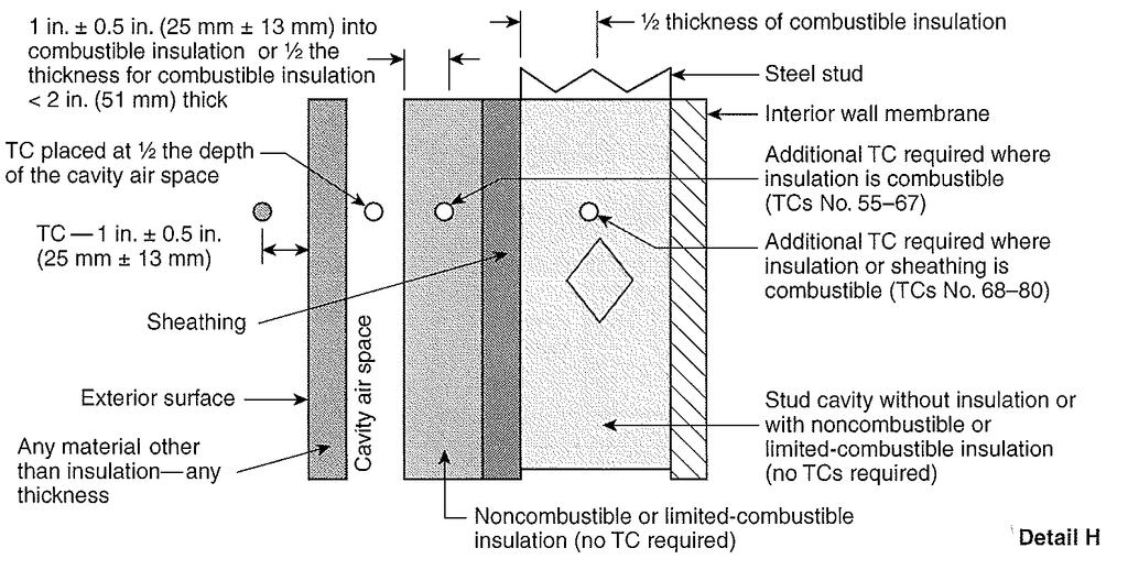
18 Temperature F :00 05:00 10:00 15:00 20:00 25:00 30:00 Time (Min:Sec) T/C 49 T/C 50 T/C 51 T/C 52 T/C 53 T/C 54 Graph No. 14 Second-story Interior Wall Surface 250 Temperature F :00 05:00 10:00 15:00 20:00 25:00 30:00 Time (Min:Sec) Graph No ft. above the Window Opening Header (Combustible Insulation) T/C 58 T/C 59 T/C 60 T/C 61 T/C 62
19 Temperature F :00 05:00 10:00 15:00 20:00 25:00 30:00 Time (Min:Sec) Graph No. 16 Left of Assembly Centerline (Combustible Insulation) T/C 55 T/C 56 T/C 57 T/C 67 Temperature F :00 05:00 10:00 15:00 20:00 25:00 30:00 Time (Min:Sec) Graph No. 17 Right of Assembly Centerline (Combustible Insulation) T/C 63 T/C 64 T/C 65 T/C 66
20 Appendix B Numerical Data
21 Time (Min:Sec) Room Gas Flow Window Gas Flow T/C 1 T/C 2 T/C 3 T/C 4 T/C 5 T/C 6 T/C 7 T/C 8 T/C 9 00: : : : : : : : : : : : : : : : : : : : : : : : : : : : : : : : : : : : : : : :
22 Time (Min:Sec) Room Gas Flow Window Gas Flow T/C 1 T/C 2 T/C 3 T/C 4 T/C 5 T/C 6 T/C 7 T/C 8 T/C 9 10: : : : : : : : : : : : : : : : : : : : : : : : : : : : : : : : : : : : : : : :
23 Time (Min:Sec) Room Gas Flow Window Gas Flow T/C 1 T/C 2 T/C 3 T/C 4 T/C 5 T/C 6 T/C 7 T/C 8 T/C 9 20: : : : : : : : : : : : : : : : : : : : : : : : : : : : : : : : : : : : : : : : :
24 Time (Min:Sec) T/C 10 T/C 11 T/C 12 T/C 13 T/C 14 T/C 15 T/C 16 T/C 17 T/C 18 T/C 19 T/C 20 00: : : : : : : : : : : : : : : : : : : : : : : : : : : : : : : : : : : : : : : :
25 Time (Min:Sec) T/C 10 T/C 11 T/C 12 T/C 13 T/C 14 T/C 15 T/C 16 T/C 17 T/C 18 T/C 19 T/C 20 10: : : : : : : : : : : : : : : : : : : : : : : : : : : : : : : : : : : : : : : :
26 Time (Min:Sec) T/C 10 T/C 11 T/C 12 T/C 13 T/C 14 T/C 15 T/C 16 T/C 17 T/C 18 T/C 19 T/C 20 20: : : : : : : : : : : : : : : : : : : : : : : : : : : : : : : : : : : : : : : : :
27 Time (Min:Sec) T/C 21 T/C 22 T/C 23 T/C 24 T/C 25 T/C 26 T/C 27 T/C 28 T/C 29 T/C 30 T/C 31 00: : : : : : : : : : : : : : : : : : : : : : : : : : : : : : : : : : : : : : : :
28 Time (Min:Sec) T/C 21 T/C 22 T/C 23 T/C 24 T/C 25 T/C 26 T/C 27 T/C 28 T/C 29 T/C 30 T/C 31 10: : : : : : : : : : : : : : : : : : : : : : : : : : : : : : : : : : : : : : : :
29 Time (Min:Sec) T/C 21 T/C 22 T/C 23 T/C 24 T/C 25 T/C 26 T/C 27 T/C 28 T/C 29 T/C 30 T/C 31 20: : : : : : : : : : : : : : : : : : : : : : : : : : : : : : : : : : : : : : : : :
30 Time (Min:Sec) T/C 32 T/C 33 T/C 34 T/C 35 T/C 36 T/C 37 T/C 38 T/C 39 T/C 40 Room T/C 41 00: : : : : : : : : : : : : : : : : : : : : : : : : : : : : : : : : : : : : : : : Room T/C 42
31 Time (Min:Sec) T/C 32 T/C 33 T/C 34 T/C 35 T/C 36 T/C 37 T/C 38 T/C 39 T/C 40 Room T/C 41 Room T/C 42 10: : : : : : : : : : : : : : : : : : : : : : : : : : : : : : : : : : : : : : : :
32 Time (Min:Sec) T/C 32 T/C 33 T/C 34 T/C 35 T/C 36 T/C 37 T/C 38 T/C 39 T/C 40 Room T/C 41 20: : : : : : : : : : : : : : : : : : : : : : : : : : : : : : : : : : : : : : : : : Room T/C 42
33 Time (Min:Sec) Room T/C 43 Room T/C 44 Room T/C 45 T/C 46 T/ C 47 T/C 48 T/C 49 T/C 50 T/C 51 T/C 52 T/C 53 00: : : : : : : : : : : : : : : : : : : : : : : : : : : : : : : : : : : : : : : :
34 Time (Min:Sec) Room T/C 43 Room T/C 44 Room T/C 45 T/C 46 T/ C 47 T/C 48 T/C 49 T/C 50 T/C 51 T/C 52 T/C 53 10: : : : : : : : : : : : : : : : : : : : : : : : : : : : : : : : : : : : : : : :
35 Time (Min:Sec) Room T/C 43 Room T/C 44 Room T/C 45 T/C 46 T/ C 47 T/C 48 T/C 49 T/C 50 T/C 51 T/C 52 T/C 53 20: : : : : : : : : : : : : : : : : : : : : : : : : : : : : : : : : : : : : : : : :
36 Time (Min:Sec) T/C 54 T/C 55 T/C 56 T/C 57 T/C 58 T/C 59 T/C 60 T/C 61 T/C 62 T/C 63 T/C 64 00: : : : : : : : : : : : : : : : : : : : : : : : : : : : : : : : : : : : : : : :
37 Time (Min:Sec) T/C 54 T/C 55 T/C 56 T/C 57 T/C 58 T/C 59 T/C 60 T/C 61 T/C 62 T/C 63 T/C 64 10: : : : : : : : : : : : : : : : : : : : : : : : : : : : : : : : : : : : : : : :
38 Time (Min:Sec) T/C 54 T/C 55 T/C 56 T/C 57 T/C 58 T/C 59 T/C 60 T/C 61 T/C 62 T/C 63 T/C 64 20: : : : : : : : : : : : : : : : : : : : : : : : : : : : : : : : : : : : : : : : :
39 Time (Min:Sec) T/C 65 T/C 66 T/C 67 00: : : : : : : : : : : : : : : : : : : : : : : : : : : : : : : : : : : : : : : :
40 Time (Min:Sec) T/C 65 T/C 66 T/C 67 10: : : : : : : : : : : : : : : : : : : : : : : : : : : : : : : : : : : : : : : :
41 Time (Min:Sec) T/C 65 T/C 66 T/C 67 20: : : : : : : : : : : : : : : : : : : : : : : : : : : : : : : : : : : : : : : : :
42 Appendix C Photographs


43 Photo No. 1 Core Wall Construction Photo No. 2 Installation of Grace Perm-A-Barrier VP


44 Photo No. 3 Installed Insulation and Technoform TE Hybrid Thermal Spacers Photo No. 4 Installation of Exterior Cladding


45 Photo No. 5 Complete Assembly (Pre-test) Photo No. 6 Interior First Story (Pre-test)


46 Photo No. 7 Interior Second Story (Pre-test) Photo No. 8 Ignition of the Interior Burner


47 Photo No. 9 Ignition of the Window Opening Burner Photo No. 10 Flame Propagation (During Test)

48 Photo No. 11 Burners Extinguished Photo No. 12 Exterior Cladding Burn Pattern (Post-test)


49 Photo No. 13 Interior First and Second Story Burn Pattern (Post-test) Photo No. 14 Exterior Cladding Removed & Burn Pattern of Insulation (Post-test)

50 Photo No. 15 Exterior Insulation Removed & Burn Pattern of AV Barrier (Post-test)
51 Appendix C Drawings
52
53
54
55
56

57
58

59
60
TEST REPORT. Report No.: G Rendered to: VELUX America LLC Greenwood, South Carolina
 TEST REPORT Report No.: G4212.01-109-44 Rendered to: VELUX America LLC Greenwood, South Carolina PRODUCT TYPE: Skylight with Curb SERIES/MODEL: Specials Dome Skylight 0.118 thickness PC smooth/0.118 thickness
ARCONIC ARCHITECTURAL PRODUCTS FIRE TEST REPORT
 ARCONIC ARCHITECTURAL PRODUCTS FIRE TEST REPORT SCOPE OF WORK CAN/ULC S134, STANDARD METHOD OF FIRE TESTS OF EXTERIOR WALL ASSEMBLIES CONTAINING ARCONIC REYNOBOND RB-160-FB REPORT NUMBER 103413434SAT-003
PERFORMANCE TEST REPORT. Rendered to: AIR VENT, INC. SERIES/MODEL: Hip Ridge Vent PRODUCT TYPE: Ridge Vent
 Architectural Testing PERFORMANCE TEST REPORT Rendered to: AIR VENT, INC. SERIES/MODEL: Hip Ridge Vent PRODUCT TYPE: Ridge Vent This report contains in its entirety: Cover Page: 1 page Report Body: 6 pages
ASTM E 1886 and ASTM E 1996 TEST REPORT. Report No.: A Rendered to: GLASSCRAFT DOOR COMPANY Houston, Texas
 Architectural Testing ASTM E 1886 and ASTM E 1996 TEST REPORT Report No.: A6457.01 801 18 Rendered to: GLASSCRAFT DOOR COMPANY Houston, Texas PRODUCT TYPE: In Swing Fiberglass Door with Side Lites SERIES/MODEL:
ASTM E 1886 and ASTM E 1996 TEST REPORT. Report No.: A Rendered to: GLASSCRAFT DOOR COMPANY Houston, Texas
 Architectural Testing ASTM E 1886 and ASTM E 1996 TEST REPORT Report No.: A6458.01 801 18 Rendered to: GLASSCRAFT DOOR COMPANY Houston, Texas PRODUCT TYPE: Fiberglass In Swing Glazed Double Doors SERIES/MODEL:
ASTM E 1886 and ASTM E 1996 TEST REPORT. Report No.: A Rendered to: GLASSCRAFT DOOR COMPANY Houston, Texas
 Architectural Testing ASTM E 1886 and ASTM E 1996 TEST REPORT Report No.: A6839.01 801 18 Rendered to: GLASSCRAFT DOOR COMPANY Houston, Texas PRODUCT TYPE: In Swing Fiberglass Double Doors with Speak Easy
NFPA 286 STANDARD METHODS OF FIRE TESTS FOR EVALUATING CONTRIBUTION OF WALL AND CEILING INTERIOR FINISH TO ROOM FIRE GROWTH
 NFPA 286 STANDARD METHODS OF FIRE TESTS FOR EVALUATING CONTRIBUTION OF WALL AND CEILING INTERIOR FINISH TO ROOM FIRE GROWTH Contego Latex Fire Barrier Intumescent (Also marketed in Canada by Pyrologistics,
TEST REPORT. Report No.: G Rendered to: SKYCO SKYLIGHTS Costa Mesa, California
 TEST REPORT Report No.: G1418.01-301-44 Rendered to: SKYCO SKYLIGHTS Costa Mesa, California PRODUCT TYPE: Fall Protection Security Bars SERIES/MODEL: FSB-1A/FSB-10A/FSB-1/FSB-10 SPECIFICATION: Occupational
CREEP PERFORMANCE TEST REPORT. Rendered to: TREX COMPANY LLC. Seclusions Composite Privacy Fence System TYPE: Composite Fence System
 Architectural Testing CREEP PERFORMANCE TEST REPORT Rendered to: TREX COMPANY LLC Seclusions Composite Privacy Fence System TYPE: Composite Fence System Report No.: Report Date: Expiration Date: 130 Derry
AAMA THERMAL PERFORMANCE REPORT. Rendered to: TORO ALUMINUM. SERIES/MODEL: Commdoor 225 Awning (Project Out) TYPE: Projecting, Awning
 TYPE: Projecting, Awning") Architectural Testing AAMA 507-12 THERMAL PERFORMANCE REPORT Rendered to: TORO ALUMINUM SERIES/MODEL: Commdoor 225 Awning (Project Out) TYPE: Projecting, Awning Report No: Report Date: 130 Derry Court
Architectural Testing AAMA 507-12 THERMAL PERFORMANCE REPORT Rendered to: TORO ALUMINUM SERIES/MODEL: Commdoor 225 Awning (Project Out) TYPE: Projecting, Awning Report No: Report Date: 130 Derry Court
TEST REPORT. Rendered to: HOMELAND VINYL PRODUCTS, INC. For: PVC Guardrail System Utilizing New Nylon/PVC Rail Mounting Bracket
 TEST REPORT Rendered to: HOMELAND VINYL PRODUCTS, INC. For: PVC Guardrail System Utilizing New Nylon/PVC Rail Mounting Bracket Report No: Report Date: 10/31/12 130 Derry Court York, PA 17406-8405 phone:
CALIBRATION REPORT. Rendered to: United States Aluminum Corp. LOCATION: Waxahachie, Texas
 CALIBRATION REPORT Rendered to: United States Aluminum Corp. LOCATION: Waxahachie, Texas Report No.: 79241.01-801-47 Calibration Date: 12/14/07 Report Date: 03/20/08 2865 Market Loop Southlake, Texas 76092
TEST REPORT UL Fire test for Heat and Visible Smoke Release for Discrete Products and Their Accessories Installed in Air-Handling Spaces
 UL 2043 TEST REPORT Fire test for Heat and Visible Smoke Release for Discrete Products and Their Accessories Installed in Air-Handling Spaces Pipe Fixings TSMI TSMI Non-metallic Tubing Channel Clip for
AAMA/WDMA/CSA 101/I.S.2/A TEST REPORT. Rendered to: MASTER WINDOW SYSTEMS, INC.
 AAMA/WDMA/CSA 101/I.S.2/A440-05 TEST REPORT Rendered to: MASTER WINDOW SYSTEMS, INC. SERIES/MODEL: Master 2000 Double Hung Window PRODUCT TYPE: PVC Double Hung Window Summary of Results Title Test Specimen
REPORT NUMBER: MID-001 ORIGINAL ISSUE DATE: Sept 27, 2013 REVISED DATE: NA
 REPORT NUMBER: 101351744MID-001 ORIGINAL ISSUE DATE: Sept 27, 2013 REVISED DATE: NA TEST REPORT EVALUATION CENTER Intertek Verification Center 8431 Murphy Dr Middleton, WI 53562 x RENDERED TO Marc Doheny
AAMA THERMAL PERFORMANCE REPORT (Revised) Rendered to: UNITED STATES ALUMINUM
 Rendered to: UNITED STATES ALUMINUM") AAMA 507-07 THERMAL PERFORMANCE REPORT (Revised) Rendered to: UNITED STATES ALUMINUM SERIES/MODEL: 7600 Projected Vent TYPE: Projecting (Awning - Single) Report No: Original Report Date: Revised Report
AAMA 507-07 THERMAL PERFORMANCE REPORT (Revised) Rendered to: UNITED STATES ALUMINUM SERIES/MODEL: 7600 Projected Vent TYPE: Projecting (Awning - Single) Report No: Original Report Date: Revised Report
NFRC U-FACTOR, SHGC, VT, & CONDENSATION RESISTANCE COMPUTER SIMULATION REPORT. (Revised) Rendered to: SPECIALTY WHOLESALE SUPPLY
 Rendered to: SPECIALTY WHOLESALE SUPPLY") NFRC U-FACTOR, SHGC, VT, & CONDENSATION RESISTANCE COMPUTER SIMULATION REPORT (Revised) Rendered to: SPECIALTY WHOLESALE SUPPLY SERIES/MODEL: 4000 / 4500 DuraGard XT Double Hung Report Number: Original
NFRC U-FACTOR, SHGC, VT, & CONDENSATION RESISTANCE COMPUTER SIMULATION REPORT (Revised) Rendered to: SPECIALTY WHOLESALE SUPPLY SERIES/MODEL: 4000 / 4500 DuraGard XT Double Hung Report Number: Original
NFRC U-FACTOR, SHGC, VT, & CONDENSATION RESISTANCE COMPUTER SIMULATION REPORT. Rendered to: CR LAURENCE CO., INC.
 FRC U-FACTOR, SHGC, VT, & CODESATIO RESISTACE COMPUTER SIMULATIO REPORT Rendered to: CR LAURECE CO., IC. SERIES/MODEL: StormWall XL Curtain Wall Report umber: Report Date: 10/14/16 FRC U-FACTOR, SHGC,
NFRC U-FACTOR, SHGC, VT, & CONDENSATION RESISTANCE COMPUTER SIMULATION REPORT. Rendered to: PARAMOUNT WINDOWS
 Architectural Testing NFRC U-FACTOR, SHGC, VT, & CONDENSATION RESISTANCE COMPUTER SIMULATION REPORT Rendered to: PARAMOUNT WINDOWS SERIES/MODEL: 6700/ 6750/ 7700/ 8700/ 8750 Report Number: Report Date:
AAMA THERMAL PERFORMANCE REPORT. Rendered to: UNITED STATES ALUMINUM. SERIES/MODEL: 3150 Curtain Wall TYPE: Glazed Wall System
 AAMA 507-07 THERMAL PERFORMANCE REPORT Rendered to: UNITED STATES ALUMINUM SERIES/MODEL: 3150 Curtain Wall TYPE: Glazed Wall System Report No: Report Date: 08/22/08 130 Derry Court York, PA 17406-8405
Urban Wildfire Interface: Exterior Wall Wildfire Testing
 Urban Wildfire Interface: Exterior Wall Wildfire Testing PN# 04018 Conducted for: WILDLAND FIRE TASK GROUP TESTING CONDUCTED ON APRIL 5 AND MAY 6, 2004 REPORT ISSUED ON: APRIL 25, 2004 Kelso, Washington
AAMA THERMAL PERFORMANCE REPORT. Rendered to: US ALUMINUM INC., DIVISION OF CR LAURENCE CO., INC.
 Archi t ectural Testing THERMAL PERFORMANCE REPORT Rendered to: US ALUMINUM INC., DIVISION OF CR LAURENCE CO., INC. SERIES/MODEL: S80 Bi-Fold Door (1" Dual Glazed) TYPE: Swinging Door - Double Report No:
PENTAGON PROTECTION USA
 PENTAGON PROTECTION USA Shock Tube Testing for Window Systems March 2009 San Antonio, Texas ABS Consulting Project Number 2127174 ABSG Consulting, Inc. 14607 San Pedro, Suite 215 San Antonio, TX 78232
CONSTRUCTION CONSULTING LABORATORY, INTERNATIONAL
 TEST REPORT: SERIES 8220 ALUMINUM SINGLE HUNG WINDOW Prepared for: 5625 E. Firestone Boulevard South Gate, CA 90280 1601 Luna Road S-UNITED, INC. Office: (972) 242-0556 Carrollton, Texas 75006 A Quality
Report Number BTC 12024F
 Report Number BTC F A FIRE RESISTANCE TEST ON A GYPROC GYPWALL PARTITION INCORPORATING A DOUBLE LAYER OF mm SOUNDBLOC EACH SIDE OF S STUDS, CONDUCTED IN ACCORDANCE WITH BS EN 4:999. Test Date: 9 th June
AAMA THERMAL PERFORMANCE REPORT. Rendered to: TUBELITE, INC. SERIES/MODEL: 200 Series Curtainwall (E2297) TYPE: Glazed Wall System
 TYPE: Glazed Wall System") AAMA 507-03 THERMAL PERFORMANCE REPORT Rendered to: TUBELITE, INC. SERIES/MODEL: 200 Series Curtainwall (E2297) TYPE: Glazed Wall System Report No: Report Date: 05/23/07 130 Derry Court York, PA 17406-8405
AAMA 507-03 THERMAL PERFORMANCE REPORT Rendered to: TUBELITE, INC. SERIES/MODEL: 200 Series Curtainwall (E2297) TYPE: Glazed Wall System Report No: Report Date: 05/23/07 130 Derry Court York, PA 17406-8405
NFRC U-FACTOR, SHGC / VT, CONDENSATION RESISTANCE COMPUTER SIMULATION REPORT. Rendered to: EARTHWISE GROUP, L.L.C. SERIES/MODEL: SS 145.
 Architectural Testing NFRC U-FACTOR, SHGC / VT, CONDENSATION RESISTANCE COMPUTER SIMULATION REPORT Rendered to: EARTHWISE GROUP, L.L.C. SERIES/MODEL: 143.095 SS 145.095 SS Baseline Product for Validation
NFRC U-FACTOR, SHGC / VT, CONDENSATION RESISTANCE COMPUTER SIMULATION REPORT. Rendered to: EARTHWISE GROUP, L.L.C.
 Architectural Testing NFRC U-FACTOR, SHGC / VT, CONDENSATION RESISTANCE COMPUTER SIMULATION REPORT Rendered to: EARTHWISE GROUP, L.L.C. SERIES/MODEL: 143.095 SH 145.095 SH 143.095 SH Common Head Baseline
NFRC U-FACTOR, SHGC / VT, CONDENSATION RESISTANCE COMPUTER SIMULATION REPORT. Rendered to: EARTHWISE GROUP, L.L.C.
 Architectural Testing NFRC U-FACTOR, SHGC / VT, CONDENSATION RESISTANCE COMPUTER SIMULATION REPORT Rendered to: EARTHWISE GROUP, L.L.C. SERIES/MODEL: 143.095 DH 143.195 DH 145.095 DH 145.195 DH Baseline
NFRC U-FACTOR, SHGC / VT, CONDENSATION RESISTANCE COMPUTER SIMULATION REPORT. Rendered to: EARTHWISE GROUP, L.L.C.
 Architectural Testing NFRC U-FACTOR, SHGC / VT, CONDENSATION RESISTANCE COMPUTER SIMULATION REPORT Rendered to: EARTHWISE GROUP, L.L.C. SERIES/MODEL: 143.191 Casement / Awning / Fixed Baseline Product
Code Compliance Research Report CCRR-0258
 Code Compliance Research Report CCRR-0258 Issue Date: 10-31-2016 Renewal Date: 10-31-2017 DIVISION: 07 THERMAL AND MOISTURE PROTECTION Section: 07 45 00 Fiber-reinforced Cementitious Panels Nichiha USA
SINGLE SLIDING WINDOW 1000 SERIES 4-1/2" FRAME SINGLE SLIDER LIFT OUT
 PERFORMANCE EVALUATION OF SINGLE SLIDING WINDOW 1000 SERIES 4-1/2" FRAME SINGLE SLIDER LIFT OUT For Dominion Doors & Windows Ltd. IN ACCORDANCE WITH: AAMA/WDMA/CSA 101/I.S.2/A440-11 AND A440S1-17 Report
PRODUCT EVALUATION REPORT
 SPUTO AND LAMMERT ENGINEERING, LLC STRUCTURAL ENGINEERS 10 SW 1 ST AVENUE, GAINESVILLE, FL 32601 PHONE: 352-378-0448 FAX: 352-373-1331 E-MAIL: sputoandlammert@mindspring.com PRODUCT EVALUATION REPORT MANUFACTURER:
AIR-INS inc. 1320, boul. Lionel-Boulet, Varennes (Québec) J3X 1P7 Tél. : (450) Fax : (450)
 J3X 1P7 Tél. : (450) Fax : (450)") 1320, boul. Lionel-Boulet, Varennes (Québec) J3X 1P7 Tél. : (450) 652-0838 Fax : (450) 652-7588 info@air-ins.com FORCED-ENTRY RESISTANCE TESTS AS PER THE ASTM F476-84(2002) TESTING PROCEDURE ON AN ENTRANCE
1320, boul. Lionel-Boulet, Varennes (Québec) J3X 1P7 Tél. : (450) 652-0838 Fax : (450) 652-7588 info@air-ins.com FORCED-ENTRY RESISTANCE TESTS AS PER THE ASTM F476-84(2002) TESTING PROCEDURE ON AN ENTRANCE
Report Number BTC 12261F
 Report Number BTC 6F A FIRE RESISTANCE TEST ON A 5m HIGH X m WIDE GYPROC SHAFTWALL SYSTEM INCORPORATING A 6mm METAL STUD FRAMEWORK CLAD WITH A DOUBLE LAYER OF 5mm GYPROC FIRELINE, EXPOSED TO THE FIRE FROM
NFRC U-FACTOR, SHGC, VT, & CONDENSATION RESISTANCE COMPUTER SIMULATION REPORT. Rendered to: PARAMOUNT WINDOWS CORPORATION
 Architectural Testing NFRC U-FACTOR, SHGC, VT, & CONDENSATION RESISTANCE COMPUTER SIMULATION REPORT Rendered to: PARAMOUNT WINDOWS CORPORATION SERIES/MODEL: ECO-View 6100/7100 Report Number: B6000.01-301-45
NFPA 1951 Standard on Protective Ensembles for Technical Rescue Incidents
 Reference: Various TIA 13-1 (SC 13-8-21/TIA Log #1098) Tentative Interim Amendment NFPA 1951 Standard on Protective Ensembles for Technical Rescue Incidents 2013 Edition Pursuant to Section 5 of the NFPA
Physical Scaling of Water Mist Protection of 260-m 3 Machinery Enclosure
 Physical Scaling of Water Mist Protection of 260-m 3 Machinery Enclosure Hong-Zeng (Bert) Yu International Water Mist Conference October 28 29, 2015 Amsterdam, The Netherlands Background To reduce the
AMCA International. Guide for Commissioning and Periodic Performance Testing of Fire, Smoke and Other Life Safety Related Dampers
 AMCA International Guide for Commissioning and Periodic Performance Testing of Fire, Smoke and Other Life Safety Related Dampers AIR MOVEMENT AND CONTROL ASSOCIATION INTERNATIONAL, INC. The International
SFI SPECIFICATION 35.2 EFFECTIVE: DECEMBER 29, 2014 *
 SFI SPECIFICATION 35.2 EFFECTIVE: DECEMBER 29, 2014 * PRODUCT: Heavy Duty Stock Car Steel Wheels 1.0 GENERAL INFORMATION 1.1 This SFI Specification establishes uniform test procedures and minimum standards
Saf-T Vent EZ Seal. Technical and Dimensional Data. Single Wall AL 29-4C Stainless Steel Special Gas Vent
 Technical and Dimensional Data Saf-T Vent EZ Seal Single Wall AL 29-4C Stainless Steel Special Gas Vent 130 Industrial Boulevard Turners Falls, MA 01376 Copyright 2001 Heat-fab, Incorporated Saf-T Vent
William R. Heiden III, P.E.
 William R. Heiden III, P.E. Georgia-Pacific Gypsum, LLC Product Evaluation Report 5/8" DensGlass Sheathing Mechanical Fastening to Steel Framing Glass-Mat Gypsum Substrate for use as Sheathing Applicable
WARNING! THIS PRODUCT MUST BE INSTALLED BY A TRAINED, AUTHORIZED RICON SERVICE TECHNICIAN.
 II. INSTALLATION T he chapter provides instructions for installing the RICON RDO2900 Series Internal Power Swing Door Operator into full-size 1992 and later Ford vans, 1990 and later Chevrolet & GMC vans,
Comparison of Styropor and Neopor Expanded Polystyrene Foam Insulations HAI Project No. 1JJB
 Ms. Andrea Bernstein PDP Product Development Engineer BASF Corporation 1609 Biddle Avenue Wyandotte, MI, 48192 Re: Comparison of Styropor and Neopor Expanded Polystyrene Foam Insulations HAI Project No.
CLASSIFICATION NOTES. Type Testing Procedure for. Crankcase Explosion Relief Valves
 CLASSIFICATION NOTES Type Testing Procedure for Crankcase Explosion Relief Valves Contents 1. Scope, Application 2. Recognized Standards 3. Purpose 4. Test Facilities 5. Explosion Test Process 6. Testing
GENERAL SPECIFICATION
 ALPHA 2001 MD TMA (Truck Mounted Attenuator GENERAL SPECIFICATION I. GENERAL A. All ALPHA 2001 MD Truck Mounted Attenuators (ALPHA 2001 MD TMA) shall be designed and manufactured by Energy Absorption systems,
BS EN :2006. Windows and doors Product standard, performance characteristics. A Report To: Mila Hardware Ltd. Document Reference:
 Exova Warringtonapt Key Industrial Park Fernside Road Willenhall West Midlands WV13 3YA T : +44 (0) 1902 722 122 F : +44 (0) 1902 727 242 E : willenhall@exova.com W: www.exova.com BS EN 14351-1:2006 Test
REARSIGHT PART NUMBER: Code: MC1 RECOMMENDED SEQUENCE OF APPLICATION
 Document # 3848 REVISION A 1/26/06 2006 TOYOTA TACOMA REARSIGHT PART NUMBER: 00016-00050 Code: MC1 RE V I S I O N A KIT CONTENTS ITEM QTY DESCRIPTION 1 1 MIRROR/MONITOR 2 1 REAR CAMERA ASSEMBLY 3 1 CAMERA
 1 TAMCO ALUMINUM CONTROL DAMPER Installation Guidelines For Series 1000, 1400, 1500, 9000, 9000 BF FOR TAMCO JACK SHAFTS REFER TO INSTRUCTIONS PROVIDED IN PARTS BOX. FOR TAMCO JUMPERS REFER TO INSTRUCTIONS
Not to be distributed outside of FM Approvals and its affiliates except by Customer
 Not to be distributed outside of FM Approvals and its affiliates except by Customer APPROVAL REPORT APPROVAL OF TUFFLITE TRIARCH MODEL ALT-CM- 1-PC AND TUFFLITE TRIARCH MODEL ALT-CM-2-CPC SKYLIGHTS PER
SFI SPECIFICATION 15.4 EFFECTIVE: JULY 20, 2010 * PRODUCT: Top Fuel and Funny Car Drag Race Drive Beadlock Wheels
 SFI SPECIFICATION 15.4 EFFECTIVE: JULY 20, 2010 * PRODUCT: Top Fuel and Funny Car Drag Race Drive Beadlock Wheels 1.0 GENERAL INFORMATION 1.1 This SFI Specification establishes uniform test procedures
SFI SPECIFICATION 3.2A EFFECTIVE: APRIL 20, 2018 *
 SFI SPECIFICATION 3.2A EFFECTIVE: APRIL 20, 2018 * PRODUCT: Driver Suits 1.0 GENERAL INFORMATION 1.1 This SFI Specification establishes uniform test procedures and minimum standards for evaluating and
AAMA/WDMA/CSA 101/I.S.2/A440-08
 PERFORMANCE TESTS IN ACCORDANCE WITH AAMA/WDMA/CSA 101/I.S.2/A440-08 Product Manufacturer: Report No.: AI-04016-U1 Rev.1 ACRYLON PLASTICS 122 PAQUIN ROAD WINNIPEG, MANITOBA R2J 3V4 204-669-2345 Report
Meeting Residential Energy Requirements with Wood-Frame Construction
 Meeting Residential Energy Requirements with Wood-Frame Construction Building Code Requirements Wood and wood-based products are widely used in building construction, due in part to favorable energy performance
2.0 TEST PROCEDURES AND RESULTS Vibration Test TEST EQUIPMENT AND INSTRUMENTATION QUALITY ASSURANCE PROGRAM 7 ATTACHMENTS
 Page No. 2 TABLE OF CONTENTS Page No. 1.0 INTRODUCTION 3 1.1 Scope 3 1.2 References 3 1.3 Test Specimen Description 3 1.4 Summary 3 2.0 TEST PROCEDURES AND RESULTS 4 2.1 Vibration Test 4 3.0 TEST EQUIPMENT
FIRE TEST REPORT FH 5078
 1222 Moonshine Road Judgeford RD1 Porirua 5381 New Zealand T +64 4 237 1170 F +64 4 237 1171 branz@branz.co.nz www.branz.co.nz FIRE TEST REPORT FH 5078 CONE CALORIMETER TEST AND NZBC ACCEPTABLE SOLUTIONS
Installation Instructions for John Deere cotton picker models: 9986 & 2-row and All-row systems included.
 Ag Leader Technology Cotton Picker Installation Installation Instructions for John Deere cotton picker models: 9986 & 9996 2-row and All-row systems included. IMPORTANT: Ensure the model numbers shown
564 Shadowbox Face (w Screen) Instructions
 Instructions") Packing List Compatibility Face Bottom Shield (2) Face Brackets (8) Screws (#8 x 3/8 Phillips) (5) Screws (#8 x 5/8 hex head) Drill Template 11/64 Drill Bit Items Used with Optional Switch Box (see note
Packing List Compatibility Face Bottom Shield (2) Face Brackets (8) Screws (#8 x 3/8 Phillips) (5) Screws (#8 x 5/8 hex head) Drill Template 11/64 Drill Bit Items Used with Optional Switch Box (see note
POWER TRIPLE LOCK* Connector System
 POWER TRIPLE LOCK* Connector System Application Specification 114-106118 23 MAY 18 Rev J NOTE All numerical values are in metric units [with U.S. customary units in brackets]. Dimensions are in millimeters.
ALPHA 70K TMA (Truck Mounted Attenuator) GENERAL SPECIFICATIONS
 GENERAL SPECIFICATIONS") ALPHA 70K TMA (Truck Mounted Attenuator) GENERAL SPECIFICATIONS I. GENERAL A. All ALPHA 70K Truck Mounted Attenuators (ALPHA 70K TMA) shall be designed and manufactured by Energy Absorption Systems, Incorporated,
ALPHA 70K TMA (Truck Mounted Attenuator) GENERAL SPECIFICATIONS I. GENERAL A. All ALPHA 70K Truck Mounted Attenuators (ALPHA 70K TMA) shall be designed and manufactured by Energy Absorption Systems, Incorporated,
Report No: Test of: Reversible aluminium/timber window. Tested to: BS :2009 Performance of windows & doors Part 2: Operation & strength
 Report No: 181947 Test of: Reversible aluminium/timber window Tested to: BS 6375-2:2009 Performance of windows & doors Part 2: Operation & strength For: A/S Peder Nielsen Beslagfabrik Norregade 25 Bronderslev
FIRE TEST REPORT FH 5728
 1222 Moonshine Road Judgeford RD1 Porirua 5381 New Zealand T +64 4 237 1170 F +64 4 237 1171 branz@branz.co.nz www.branz.co.nz FIRE TEST REPORT FH 5728 CONE CALORIMETER TEST AND NZBC VERIFICATION METHOD
2018+ Mustang Lower Grill and Chin Spoiler Kits Installation Instructions P/N: (R K945) P/N: (R F775)
 P/N: (R F775)") 2018+ Mustang Lower Grill and Chin Spoiler Kits Installation Instructions P/N: 422081 (R1318-17K945) P/N: 422082 (R1318-17F775) 39555 Schoolcraft Rd, Plymouth MI, 48170 800.59.ROUSH 2018+ Mustang Lower
2018+ Mustang Lower Grill and Chin Spoiler Kits Installation Instructions P/N: 422081 (R1318-17K945) P/N: 422082 (R1318-17F775) 39555 Schoolcraft Rd, Plymouth MI, 48170 800.59.ROUSH 2018+ Mustang Lower
Photograph 1, Current feed to connector test loop
 Photograph 1, Current feed to connector test loop Photograph 2, control conductor and instrument leads outside test chamber Page 3 of 6 Photograph 3 Salt Fog Chamber with Connector Loop Photograph 4, Connector
Fort Bend ISD Fire Origin and Cause 3130 Lake Olympia Parkway Missouri City, TX Client File: COMP Haag File:
 This document has been electronically signed and/or sealed in accordance with the applicable State Board of Professional Engineering requirements. Fort Bend ISD Fire Origin and Cause 3130 Lake Olympia
A. This Section includes the following types of sectional overhead doors:
 SECTION 08361 - SECTIONAL OVERHEAD DOORS PART 1 - GENERAL 1.1 RELATED DOCUMENTS A. Drawings and general provisions of the Contract, including General and Supplementary Conditions and Division 1 Specification
M36 LED Recessed Quickship
 Date: Customer: Project: Type: Qty: M36 Order Code: - 1B35 - - LW - - - WH - UNV - Series QL36 M36 LED Multi Mount Form Quickship QL36R1 Continuous Flange Quickship (Flanged Endcaps) 1B35 Light Engine
Report No 2370/ This Report consists of 40 pages. Authority & date Request by Client dated 25 November 2010
 Test Report Report No 2370/7612199 This Report consists of 40 pages Client Smarts Systems Limited Arnolds Way Yatton BS49 4QN Authority & date Request by Client dated 25 November 2010 Items tested 3 off
ECO# 1801 REVISION# 000 ES DATE
 SmokeShield Elevator ECO# 1801 REVISION# 000 ES 10-458 DATE 08/25/2018 ECO# 1801 REVISION# 000 ES 10-458 DATE 08/25/2018 Section 1 Table of Contents Section 2 Safety Check List 2 Section 3 Freight Receiving
INSTALLATION INSTRUCTIONS WALL MOUNT RANGE HOOD WITH M600 OR M1200 BLOWER
 WARNING - TO REDUCE THE RISK OF FIRE, USE ONLY METAL DUCTWORK C U L R Read and Save These Instructions All Hoods Must Be Installed By A Qualified Installer INSTALLATION INSTRUCTIONS WALL MOUNT RANGE HOOD
HARDWARE KIT INSTALLATION GLOVES
 COIL MOUNT STEEL DUCT MOUNT DUCTBOARD MOUNT CLAMP PLATE Z-BRACKET PCO BRACKET SHIELDED LAMP ASSEMBLY ALSO INCLUDED BALLAST TECH MANUAL HARDWARE KIT INSTALLATION GLOVES Rev 1 Issued: 09/03/2014 SERVICE
Blast Protection Damper
 Protection Damper plate shown as transparent height width 250mm wide 6.35mm thick blast plate bolted to damper frame 178mm 250mm standard depth 76mm standard flange Application The damper is designed for
RECEIVING AND INSPECTION EXAMINE ALL COMPONENTS FOR POSSIBLE SHIPPING DAMAGE PRIOR TO INSTALLATION.
 Non-Welded Grease Duct Systems Installation, Operation, and Maintenance Manual FOR YOUR SAFETY TWO MAJOR CAUSES OF GREASE DUCT RELATED FIRES: (1) FAILURE TO MAINTAIN REQUIRED CLEARANCE (AIR SPACE) TO COMBUSTIBLE
Second Correlating Revision No. 3 NFPA [ Section No ]
![Second Correlating Revision No. 3 NFPA [ Section No ]](/thumbs/76/73230477.jpg "Second Correlating Revision No. 3 NFPA [ Section No ]") Second Correlating Revision No. 3 NFPA 1991 2015 [ Section No. 2.3.2 ] 2.3.2 ASTM Publications. American Society for Testing and Materials, 100 Barr Harbor Drive, West Conshohocken, PA 19428 2959. ASTM
Second Correlating Revision No. 3 NFPA 1991 2015 [ Section No. 2.3.2 ] 2.3.2 ASTM Publications. American Society for Testing and Materials, 100 Barr Harbor Drive, West Conshohocken, PA 19428 2959. ASTM
Safe-Stop TMA (Truck Mounted Attenuator) GENERAL SPECIFICATIONS
 GENERAL SPECIFICATIONS") Safe-Stop TMA (Truck Mounted Attenuator) GENERAL SPECIFICATIONS I. GENERAL A. All Safe-Stop Truck Mounted Attenuators (Safe-Stop TMA) shall be designed and manufactured by Energy Absorption Systems, Incorporated,
Safe-Stop TMA (Truck Mounted Attenuator) GENERAL SPECIFICATIONS I. GENERAL A. All Safe-Stop Truck Mounted Attenuators (Safe-Stop TMA) shall be designed and manufactured by Energy Absorption Systems, Incorporated,
Test Report NO. AJHL FB Date: JUN.21, 2016 Page 1 of 6
 Test Report. AJHL1606005783FB Date: JUN.21, 2016 Page 1 of 6 IGEPA GROUP GmbH & CO., KG SACHSENFELD 4, 20097 HAMBURG, GERMANY The following sample(s) was / were submitted and identified on behalf of the
HDI inch Choke Position Indicator User s Manual Rev Indicator Gauge Linear Potentiometer
 HDI 2522 4-inch Choke Position Indicator User s Manual Rev 2 New 2522 Indicator Gauge Linear Potentiometer w/open Housing 2200 Indicator Gauge Linear Potentiometer TABLE OF CONTENTS HDI 2522 4-inch Indicator
INSTALLATION INSTRUCTIONS WALL MOUNT RANGE HOOD WITH M600 OR M1200 BLOWER
 WARNING - TO REDUCE THE RISK OF FIRE, USE ONLY METAL DUCTWORK C U L R Read and Save These Instructions All Hoods Must Be Installed By A Qualified Installer INSTALLATION INSTRUCTIONS WALL MOUNT RANGE HOOD
PRODUCT SPECIFICATION
 of 3 C Section : For the 200222, 2002323, 2002444, 20025, 200252, 200252, 20026, 200262, 200262, 20028, 200283, 200284, 2002822, 2002824, 200283, 2002832, 2002833, 2002834 and 2002835 series parts..0 GENERAL
Testing of Baier Plasterboard to AS/NZS (Electronic copy (PDF format) original signed by author) Materials Scientist.
 original signed by author) Materials Scientist.") DC1333 Testing of aier Plasterboard to AS/NZS 2588 (Electronic copy (PDF format) original signed by author) Author: Neil Lee Materials Scientist Reviewer: ryan Keen Senior Technician Contact: RANZ Limited
DC1333 Testing of aier Plasterboard to AS/NZS 2588 (Electronic copy (PDF format) original signed by author) Author: Neil Lee Materials Scientist Reviewer: ryan Keen Senior Technician Contact: RANZ Limited
Test Report No. AJHL FB Date: OCT.26, 2016 Page 1 of 6
 Test Report No. AJHL1609010810FB Date: OCT.26, 2016 Page 1 of 6 SOYANG TECHNICAL TEXTILE (ZHEJIANG) CO., LTD NO.36 JINNIU ROAD, JIANSHAN DISTRICT, HAINING CITY, ZHEJIANG PR., CHINA The following sample(s)
CRASH TEST REPORT FOR PERIMETER BARRIERS AND GATES TESTED TO SD-STD-02.01, REVISION A, MARCH Anti-Ram Bollards
 CRASH TEST REPORT FOR PERIMETER BARRIERS AND GATES TESTED TO SD-STD-02.01, REVISION A, MARCH 2003 Anti-Ram Bollards Prepared for: RSA Protective Technologies, LLC 1573 Mimosa Court Upland, CA 91784 Test
INSTALLATION INSTRUCTIONS WALL MOUNT HOOD
 Read and Save These Instructions All Hoods Must Be Installed By A Qualified Installer INSTALLATION INSTRUCTIONS WALL MOUNT HOOD Read All Instructions Thoroughly Before Beginning Installation WARNING -
Test Report No. AJHL FB-2 Date: OCT.24, 2016 Page 1 of 6
 Test Report. AJHL1610011324FB-2 Date: OCT.24, 2016 Page 1 of 6 POSTER AND PANEL CPERE ANDORRA, SN, POL. IND, ILLA,SUD, NAUS, 4, 5, I6,08650, SALLENT, BARCELONA, SPAIN The following sample(s) was were submitted
ThermoLite 110W-330W Solar Panel Installation Instructions
 ThermoLite 110W-330W Solar Panel Installation Instructions INSTALL APPLICATIONS SUPPORTED BY THIS GUIDE: 1. Trailer Roof Top Mounted 2. Bus Roof Top Mounted 3. Tractor Fairing Mounted 40W and 110W Replacement
model E Spray nozzles vk810 - vk817
 Page 1 of 10 1. DESCRIPTION Viking Model E, 3D Spray Nozzles are open type spray nozzles designed for directional spray applications in fixed fire protection systems. They have an open design only (nonautomatic)
U-Factor, Solar Heat Gain Coefficient, Visible Transmittance and Condensation Resistance Calculation Report
 U-Factor, Solar Heat Gain Coefficient, Visible Transmittance and Condensation Resistance Calculation Report REPORT NO: NCTL-110-16086-01 SIMULATION DATE: 08/30/13 REPORT DATE: 08/30/13 Client: Product
INTERIOR INSTALLATION
 HOOK ON CROSS CONNECTOR CLAMP AT ALL INTERSECTIONS OF S 4-1 4" PANEL 1/2" x 1-1/2" 16 GA CR CHANNEL PRIMARY AT 48" O.C. MAX SPACING, TYPICAL. PANEL 1 1 2 " 12 GA HANGER WIRE, BY OTHERS, NOT BY HUNTER DOUGLAS.
37SCENE 46SCENE 79SCENE
 Installation and Operation Instructions LED SCENE LIGHT LED SCENE LIGHT 37SCENE 46SCENE 79SCENE 37SCENE 46SCENE Introduction The 37SCENE, 46SCENE, 79SCENE LED Scene Lights are designed for the emergency
Originally Issued: 09/26/2012 Revised: 09/29/2017 Valid Through: 09/30/2018
 EVALUATION SUBJECT: FAKRO FX, FV FVE, FX-EL, FV-ELA, AND FVE-ELA SKYLIGHTS REPORT HOLDER: FAKRO GROUP 144A WEGIERSKA STREET 33 300 NOWY SACZ POLAND 48 18-444 0444 www.fakro.info CSI Division: 08 00 00
SFI SPECIFICATION 32.1 EFFECTIVE: MARCH 24, 2009 *
 SFI SPECIFICATION 32.1 EFFECTIVE: MARCH 24, 2009 * PRODUCT: Stock Car Fuel Cell Bladder 1.0 GENERAL INFORMATION 1.1 This SFI Specification establishes uniform test procedures and minimum standards for
2-row and All-row systems included.
 Ag Leader Technology Cotton Picker Installation Installation Instructions for John Deere cotton picker models: 2-row and All-row systems included. IMPORTANT: Ensure the model numbers shown above correspond
BUREAU OF STANDARDS. Effective Date: 8/19/2016 Section No. 4. Version: 1.2 Procedure No. 3
 BUREAU OF STANDARDS Effective Date: 8/19/2016 Section No. 4 Version: 1.2 Procedure No. 3 TITLE: LP Gas Bulk Plant Final Inspection PURPOSE: This document details the procedures used to conduct a Final
GENERATOR SHELTER IMPACT TEST REPORT (.08 Material)
") GENERATOR SHELTER IMPACT TEST REPORT (.08 Material) Florida Division of Emergency Management 2555 Shumard Oak Boulevard Tallahassee, FL 32399 Office: 850-413-9969 Department of Management Services 4050
GENERATOR SHELTER IMPACT TEST REPORT (.08 Material) Florida Division of Emergency Management 2555 Shumard Oak Boulevard Tallahassee, FL 32399 Office: 850-413-9969 Department of Management Services 4050
Thermal Testing Results
 Thermal Testing Results Testing completed on 35.75 x 83 Six Panel Oak Grain Slab. Testing preformed and documented by Weber Manufacturing Technologies Inc. Page 2 of 9 1 Introduction Weber Manufacturing
Architect s Guide for Detailing & Specifying Access Floor Air Plenums
 Access Floors Architect s Guide for Detailing & Specifying Access Floor Air Plenums Access Floors to the Power of 1 Access floor air plenum integrity begins with proper design and specification. 2 Architect
PERMA ROLL 75. installation instructions Automatic Roll-up Door. note:
 p PERMA TECH, INC. 363 hamburg street buffalo, new york 14204 phone: (716) 854 0707 fax: (716) 854 0774 1 800 362 7325 www.permatechinc.com PERMA ROLL 75 installation instructions Automatic Roll-up Door
Standard Installation Fire/Smoke Damper Models: FR1, FR2 Smoke Damper Models: SR1, SR2
 Reprinted Feb 2013 APPLICATION These dynamically rated fire/smoke and smoke dampers are intended to restrict the passage of smoke. The dynamically rated fire/smoke dampers are also intended to restrict
Aug07 Rev A All Paragraphs Revised
 Qualification Test Report Universal MATE-N-LOK* Connector 110-213 28Aug07 Rev A All Paragraphs Revised 1. INTRODUCTION 1.1. Purpose 1.2. Scope Testing was performed on Universal MATE-N-LOK* connectors
TEST REPORT No. : SHCCM Date : May. 17, 2013 Page: 1 of 5
 Page: 1 of 5 IGEPA GROUP GMBH & CO. KG SACHSENFELD 4, 20097 HAMBURG, GERMANY The following sample(s) was/ were submitted and identified on behalf of the client as: Sample Name : MASTER JET S PREMIUM MESH