eapu Installation Manual
|
|
|
- Jesse Rogers
- 5 years ago
- Views:
Transcription
1 eapu Installation Manual #61033 REV A 1
2 Topic Table of Contents Page Number System & Installation Overview 3-5 Pallet Contents 6 Mounting the Frame Rail Unit 7-12 Battery Installation Frame Brackets & Clips Shore Power Standard Installation 18 Shore Power interrupt Installation 19 Shore Power Y Installation 20 UBB Installation 21 Evaporator Installation Evaporator, Kenworth Evaporator, International Wall Mount Evaporator Evaporator, Cascadia Evaporator, Volvo Thermostat Installation 36 Ignition Cutout Circuit Installation OEM Fan Harness Installation Coolant Heater Hose Installation Fuel Line Installation 53 DC Cables Camlock Connectors Reefer Link XD System Testing #61033 REV A 2
. 2.")
3 System & Installation Overview The eapu system consists of interior and exterior modules. Interior and Exterior Modules System modules can be divided into two types: 1. Interior modules: The interior modules installed in the bunk are the evaporator, thermostat, and the Under Bunk Box, (battery charger, inverter, relay pack, and electrical connections). 2. Exterior modules: Frame mounted APU. Fig 1 (below) provides an approximate location of interior and exterior modules following a typical installation. Fig 1: Location of the frame rail unit may vary depending on truck type #61033 REV A 3
 Thermostat Evaporator Tools & Parts included in the")
 and lock nuts (4) (or other as specified due")


4 System & Installation Overview eapu Components: Frame Rail Unit UBB (Power Module) Thermostat Evaporator Tools & Parts included in the Kit: Evaporator w/1/4" 20 X 2.5" mounting bolts (4) and lock nuts (4) (or other as specified due to installation variation) Evaporator power cord w/split loom Refrigerant lines w/split loom Evaporator cutout template 10' water drain tube w/two clamps (2) and rubber drain end attached Cables #1, 2, 3, 4, amp Fuse holder with fuse Shore power outlet 2 ½ " floor collars (2) w/lock nut #61033 REV A 4
5 System & Installation Overview Power Module with Inverter, Charger, Relay Pack 20 ignition cutout wire w/extension harness as appropriate Thermostat w/10-24 mounting screws (2) 5/8" to 3/4" hose adapters (2) 3/4" x 3/4 hose connectors (2) Shore Power cord Medium cable ties (25) Water hose clamps (10) Long cable ties (25) 3/4" coolant hose Frame mounted APU 5/8" coolant hose APU back brackets (2) Fuel pick-up tube w/hose and clamps attached Grade 8 bolt sets (4) with 5/8" bolts and washers Fuel line Power strip w/velcro Additional Tools Required for the Installation Process ½ drill Lift cart 1-3/4 hole saw 2-1/2 hole saw 3 hole saw 3/8 ratchet Extension cords ½ socket 9/16 socket 11/16 wrench Water hose cutter Nut drivers Screwdrivers ½ drive ratchet 15/16 socket Hose pinch pliers Anti-corrosion spray Bucket Vacuum cleaner PPE Safety: Be sure to follow the safety guidelines listed below: Always wear safety glasses during all procedures Ensure the work area is clear of trips, slips or fall hazards prior to starting work Make sure you are wearing non-conductive shoes prior to working with electrical components Do not lift heavy objects by yourself; use a lift cart or 2- person procedures #61033 REV A 5
 Shore power kit Driver s packet Please take the time to inventory the contents of the")

6 Pallet Contents The APU system will arrive on a pallet and will include the following components: Frame rail unit Under bunk power module (UBB) Installation kit with cables, harnesses, fuses and thermostat Frame bracket Evaporator OEM harness Exhaust re-route kit (Optional: dependent on make/model of truck) Shore power kit Driver s packet Please take the time to inventory the contents of the pallet. Place the individual boxes near the area of the truck where they will be installed. Frame rail unit UBB Installation kit Evaporator Driver s packet OEM harness Exhaust re-route Frame bracket Shore power Contents Truck Location Passenger side, behind fuel tank Passenger side box Driver s side box Passenger side box Driver s door pouch Driver s side box Under step deck Mount to APU Driver s side box #61033 REV A 6

7 Mounting the APU s Frame Rail Unit Special Tools Needed Torque Wrench (212 Ft/Lbs) 2-Lifting carts (600 Lbs. capacity) The APU is an x x 26.7" box mounted on the frame rail. It weighs approximately 500 pounds and requires 24" of frame rail space for mounting. The APU is pre-assembled & includes four major components: 1. AGM Battery Bank: The AGM battery bank is independent of the truck batteries. Installation of the batteries will need to be completed before the frame rail unit can be mounted on the truck. 2. Coolant Heater: The coolant heater is located above the battery bank, on the top level of the APU. The coolant heater produces heat for the truck s engine as well as for the heater cores in the truck s interior. 3. A/C Compressor: The A/C compressor is located above the battery bank in the frame rail unit. The compressor uses a run capacitor and a start capacitor. The compressor is protected by a refrigeration pressure switch located on the receiver/dryer. 4. A/C Condenser: The A/C condenser is located above the battery bank next to the A/C compressor. The modules in the APU (described above) are pre-connected. The A/C compressor is connected to the (interior located) evaporator module using QUICK DISCONNECT FITTINGS. These connectors are located on the back side of the APU. The A/C system comes pre-charged with R 134A refrigerant. Consideration: Protect your APU from the elements with a quarter fender add-on. Fender installation should take place before you mount the frame rail unit to ensure that the fender does not interfere with the positioning of the APU. Recommended alternator requirements: 25 additional AMPs of alternator capacity per each AGM battery in your APU. (In most cases, a 270 AMP truck alternator will suffice) The alternator has remote voltage reading capability #61033 REV A 7
 other frame locations may be available, including on the driver s side, behind the fuel tank.")
8 Mounting the APU s Frame Rail Unit The typical location for the frame rail unit is the passenger side of the truck, behind the fuel tank, in front of the drive wheels. If space is not available (on the passenger side) other frame locations may be available, including on the driver s side, behind the fuel tank. Alternative Exterior Mounting Locations: #61033 REV A 8
 away from the cart handles. 2. Push the frame rail unit into position next to the truck s frame to test frame fit. 3.")
. 6. Move air lines or other obstacles 7. Add heater hoses to the rear of the frame rail unit. 8.")
9 Mounting the APU s Frame Rail Unit 1. Place the APU s frame rail unit on a lifting cart or on a transmission jack. If using a lift cart, place the APU with the back side (APU) away from the cart handles. 2. Push the frame rail unit into position next to the truck s frame to test frame fit. 3. Determine the frame attachment hardware needed for this installation. 4. Pull the frame rail unit away from the frame and prep the truck & the APU, prior to mounting. 5. Change the truck s exhaust route (if needed, see next page). 6. Move air lines or other obstacles 7. Add heater hoses to the rear of the frame rail unit. 8. Add APU Reefer Link DC Connectors if Reefer Link option is a part of this installation. 9. Cut tie straps holding hoses and harnesses, behind the frame rail unit. The drawing (above) shows a top view of the APU against the frame of the truck. The drawing also shows the APUs frame contact points and the space between the truck s frame and the APU s enclosure. Standard L- Brackets are seen in the above drawing. These brackets are used as Clamps to secure the APU to the trucks frame. Alternatives to the L- Brackets include Direct to truck frame mounting. #61033 REV A 9


10 Exhaust Kit: 45 Elbows Mounting the APU s Frame Rail Unit The 45 Exhaust Kit is used on most trucks with horizontal exhaust systems (belly exhaust). The 45 Exhaust Kit is used when the truck's factory exhaust exits near the APU s frame rail unit. #61033 REV A 10
11 Mounting the APU s Frame Rail Unit 10. Push the frame rail unit back into position next to the truck s frame to confirm frame fit. 11. Confirm that clearance is available on all sides of the APU. 12. Confirm that the lift has raised the frame rail unit high enough, against the truck s frame, to allow the top 2 clamp mounting bolts to clear the top of the truck s frame. 13. Insert two (Grade 8) 5/8" bolts and flat washers (included) through the single holes at the top of the L- Brackets. The top bolts are routed over the top of truck s frame. 14. Leave about ½ clearance between the top of the frame and the 2 bolts. (The ½ clearance is only used to decrease friction during the bolt tightening procedure. Make sure that the 2 top bolts are resting on top of the truck s frame after the frame clamp installation procedure has been completed. 15. Start the bolts and continue to turn them until they are through the APU s welded frame nut. The APU s frame rail unit should still be supported by the lifting cart or transmission jack. 16. Lower the lifting device just until the top APU mounting bolts make contact with the top of the truck s frame. It is important to make sure that the lowering of the APU (at this point) has exposed the top two (of the lower four) bolt holes, needed for frame mounting. 17. Place two bolts, with washers (provided), through the upper (of the two lower four mount holes) on the back bracket. Use the lower of the (two lowest) mounting holes only when mounting the APU on a large frame Volvo truck. 18. Tighten the four mounting bolts in a cross sequence and focus on keeping the frame rail unit flush contact with the truck s frame face. 19. Remove the APU lift once solid constant contact is made between the APU and the truck s frame. 20. All bolts should then be torqued to 212 foot pounds, dry torque. Warning: Torque must be measured as a dry torque without use of lubrication or antiseize product. Improper torque of the mounting bolts can lead to loss of clamp force or bolt failure. 21. All bolts should show the same exposed thread count from the weld nut. 22. There should be no gaps between the truck s frame and the APU s frame guides. #61033 REV A 11

. c.")

12 23. The top mounting bolts should be resting on the top of the truck s frame. Mounting the APU s Frame Rail Unit 24. Add a vertical witness mark to each bolt after the proper torque level has been met. a. Make sure that the mark extends to the frame bracket. b. The mark verifies proper torque (212 foot pounds, dry torque). c. The mark is used as a visual sign of bolt head movement. 25. Affix Service Label on the top of the APU cover. a. Use marker to write in date, 6 months from installation date. b. Date entered is the next Torque Check Service Date. #61033 REV A 12
13 Battery Installation Battery installation must be completed before the frame rail unit can be mounted to the truck s frame. If you do not have 2 lift carts, place the batteries on a sturdy table. Lift the frame rail unit onto a lift cart. Move to an open area big enough to handle two lift carts. Position four AGM batteries onto a lift cart; position them so the positive terminals and negative terminals line up. Remove the terminal protection caps from the battery terminals and discard. Apply a drop of Loctite 243 to all battery terminal threads Assemble positive cable harness, part number 32062, to positive terminals. Fully tighten first two terminals and last terminal. Leave third terminal loose to allow for battery position adjustment later. Assemble negative cable harnesses, part number (a qty of 3) to negative terminals. Fully tighten the first three negative terminals. Assemble AGM ground cable harness, part number (a qty of 2) to last negative terminal and fully tighten. Ensure that the frame rail unit battery opening is lined up with the battery lift cart. Lock the wheels to prevent separation. Slide all 4 batteries into frame rail unit battery area. Stop when the batteries are about 2 from the end of the frame rail unit. Insert the battery hold down bracket with the flat side down on top of the batteries. Adjust the position of the batteries to have approximate equal clearance between each battery. Install an SAE washer onto each of the 5 cap screws. Start all bolts by hand to prevent cross-threading. Install center cap screw (A) located between the second and third batteries, into the hold down bracket. Finger tight only. From one end, install cap screw (B) between the first and second batteries, into the hold down bracket. Finger tight only. From other end, install cap screw (C) between the third and fourth batteries, into the hold down bracket. Finger tight only. From both ends, install cap screws (D & E) located on each end of the hold down bracket. Finger tight only. Check that cap screws D & E are perpendicular with the base and the batteries are equally spaced. #61033 REV A 13
14 Use an impact driver and 1/2 hex socket to tighten all cap screws until the driver just begins to click. Do not over-tighten. Using a torque wrench set to 40 In/Lbs with a 1/2 hex socket, set cap screws in this sequence A, B, C, D, E. (Center, next to center 2X, ends 2X) Install red 14-gauge wire and large red battery cable from the front battery onto the battery separator. Fully tighten. Install two ground cables (part number 32051) from the black Marinco connectors on the frame rail unit to the back battery negative terminal. Tighten. #61033 REV A 14
 Components: 2- Steel channels 4-5.5 (5/8 ) Grade 8 mounting bolts 4-5/8 Grade 8 washers The APU includes nuts welded onto the frame. These nuts receive the 5.5 GR8 mounting bolts.")

15 Frame Brackets & Clips Depending on the truck make and model, there are three methods to attach the APU to the truck frame Standard Mount Kit Frame Clips Mount Kit Offset Kit Direct Mount Standard Mount Kit (91717) Components: 2- Steel channels (5/8 ) Grade 8 mounting bolts 4-5/8 Grade 8 washers The APU includes nuts welded onto the frame. These nuts receive the 5.5 GR8 mounting bolts. The two back brackets are used to sandwich the truck s frame to the frame rail unit of the APU. The back bracket s punched holes match the hole pattern on the back side of the frame rail unit. The bottom holes are only used on large frame trucks. Frame Clips Mount Kit (Used when obstacles prevent the use of the standard brackets) This kit ( 91712) includes: 4- Steel frame clips 4-6 (5/8 ) Grade 8 bolts 4-5/8 Grade 8 washers #61033 REV A 15


16 Frame Brackets & Clips The frame rail unit of the APU includes nuts welded onto the frame. These nuts receive the 6 Grade 8 mounting bolts. Offset Kit (Used when space on the truck frame is not available due to obstacles) This kit includes 2 Z brackets and mounting hardware. The offset brackets can be used in a number of ways that will enable the frame rail unit to be secured to the truck s frame. #61033 REV A 16
17 Frame Brackets & Clips Direct Mount: The Frame rail unit will be mounted directly to the truck s frame rail. Kit # includes: 4 5/8 Grade 8 bolts 4-5/8 Grade 8 washers 4-5/8 Grade 8 nuts #61033 REV A 17

18 Standard Shore Power Installation Shore Power Kit #91610 includes a male, 120 V receptacle and a harness. If a factory installed shore power or Cab Power is present on the truck, there are optional installation kits available. Position the receptacle on the driver s side of the truck, just behind and below the driver s door. Make sure the area is free from obstacles. Drill a 1 7/8 hole for the receptacle. Insert the receptacle into the hole and attach with the rear mounted nut. Ensure that the inlet plug receiver s orientation is straight up and down. Insert the male plug into the back side of the plug receiver. Using the tab on top of the receiver, lock the plug receiver in place. Route the shore power harness from the receiver to the floor collar under the bunk bed. Plug the shore power harness into the back side of the UBB (marked shore power ) Secure the harness to the underside of the truck sleeper section using the wire ties and p-clips. #61033 REV A 18
19 Shore Power Interrupt Installation When a truck includes the Cab Power option, one of two systems is present. 1. Cab Power distribution box with Bunk outlets 2. Cab Power distribution box with Bunk outlets and a Truck Inverter If #1 is present, then the appropriate kit is Shore Power Kit is # This kit includes two cables; and Unplug the connector on the bottom of the Cab Power Box. The Cab Power Box is located in the driver s side box. Plug the male receptacle into the 120VAC outlet located on the back side of the UBB (see diagram below). Route cable #32591 from the UBB to the Cab Power Box. Plug the connector end of cable #32591 into the bottom receptacle on the Cap Power Box. Plug the black connector end of IFS cable #32590 into the cable originally removed from the Cab Power box (see diagram below). Route cable #32590 to the back of the UBB. Plug the Molex connector on the end of cable into the connector on the back of the UBB box labeled Shore Power. Secure the cables. #61033 REV A 19

20 Shore Power Y Installation When a truck includes the Cab Power option, one of two systems is present. 1. Cab Power distribution box with Bunk outlets 2. Cab Power distribution box with Bunk outlets and a Truck Inverter If #2 is present, then Shore Power Kit #91602 is the appropriate kit. This kit includes two cables; and Locate the Factory installed inverter. Unplug the Shore Power connector on the input side of the inverter. Plug the single end of the Y connector into the cord removed from the inverter. Plug either one of the remaining Y connector ends into the input receptacle on the inverter. Plug the black connector end of cable #32090 into the remaining connector on cable # Route cable #32590 from the connection point to the back side of the UBB box. Plug the Molex connector end of cable #32590 into the Molex plug labeled Shore Power, this connector is located on the back side of the UBB. Secure cables. #61033 REV A 20
 needs to be in a location so the user can see and access the inverter s face. The UBB should be visible from the storage access door.")
21 UBB Installation The UBB is the connection hub for the APU system. The UBB is installed on the bunk floor, under the bed. The side opening (show diagram) needs to be in a location so the user can see and access the inverter s face. The UBB should be visible from the storage access door. Position the UBB on the bunk floor Locate the floor collar and place it where you want to create the pass-through hole to the underside of the bunk. Check under the bunk for any obstacles prior to drilling a hole. You will need clearance for a 3 circle. Drill a ¼ pilot hole in the center of the spot to be used for the floor collar. Check under the bunk floor to confirm there is enough space. Use a 2-1/2 hole saw and cut the hole in the bunk floor. Place the floor collar into the hole and secure with the retaining nut. Bolt or screw the UBB in place with the included fasteners UBB, Cover Removed Floor Collar #61033 REV A 21
22 Evaporator Overview: Standard Evaporator Installation Depending on the truck make and model, there are different installation instructions. This manual will provide instructions for the following alternatives: Standard installation Kenworth 680 installation International installation Wall Mount Bracket installation Volvo installation Cascadia Installation The Evaporator is installed on a high shelf in one of the bunk s closets or on the back wall shelf; typically on the same side of the truck as the exterior APU unit is installed. This assures that the refrigeration lines will have the length to be properly connected. The evaporator assembly includes two air conditioning refrigeration lines, a power cord and a plastic drain tube. The air conditioner is shipped with R134A refrigerant in the condensing unit. Standard Installation: Confirm that the Evaporator will fit into the desired location. Using the evaporator template, mark the center hole location for the two cutouts. Using a 3.5" hole- saw, cut the 3.5 marked hole in the shelf where the evaporator will be located. Using a 1.75 hole-saw, cut the 1.75 marked hole in the correct hole location. Using a 2.5 hole-saw cut an opening through each closet shelf, in line with the 3.5 inch hole above. Cut this same hole in any shelving between the evaporator shelf and the bunk floor. Orient the holes so that they create a direct path to the compressor/condenser assembly (frame rail unit of the APU). Identify the desired location in the closet floor for a hose pass through. A 2.5" floor collar will be inserted into the closet floor used to protect the refrigerant lines, condensate drain tube, & the power cord as each pass though the closet floor. Check under the closet floor (outside) to make sure there are no restrictions or obstacles. NOTE EXHAUST SYSTEM ROUTING BEFORE CUTTING HOLE. Do not locate the pass-through hole above the truck s exhaust system. Using a 1/4" drill bit, mark the center for the 2.5" floor collar hole. Drill a pilot hole and leave drill and drill bit in place as you look at the drill bit from under the closet to make sure that the space (where the hole is to be) is big enough for the 2 ½ floor collar. #61033 REV A 22

 through the closet")
23 Using a 3 hole saw cut only through the carpet and floor insulation stopping when the 3 hole saw is resting on the metal floor. Change the hole saw blade to a 2 ½ size and cut a 2 ½ hole into the closet floor. Insert the 2.5" floor collar into the hole. Attach the floor collar ring to the bottom side of the 2 1/2" floor collar (from the outside). Install the evaporator drain tube (clear) onto the rear of the evaporator assembly. Starting at the destination location of the evaporator, feed the refrigerant lines, the evaporator s power cord, and the water drain tube (already connected to the evaporator) through the closet shelves. Position the evaporator in the desired location. Secure the evaporator into position using the included hardware. Install the aluminum air filter on the rear of the evaporator. Confirm that the evaporator s refrigerant lines and drain hose are not kinked or pinched where they pass through each closet shelf. Carefully pass each of these through the closet floor collar: a. Evaporator drain tube b. Large refrigerant fitting + hose c. Small refrigerant fitting + hose Do not pass the electric cord through the floor collar unless the route to the UBB (harness connection point) has been established. The direct route to the UBB may be easier to manage if the harness remains in the bunk. Secure the refrigerant hoses, drain hose and electrical harness to the back wall of the closet. Determine the harness route to the UBB for the evaporator s power cord. Secure the evaporator s power cord. #61033 REV A 23
24 Step 1: Prep International Evaporator Installation Remove the plastic cover from the evaporator. Peel one side of the cover and the top off and the opposite side will disconnect the Velcro connections Remove the 4 mounting legs, the bolts holding the legs and the Velcro strips near each leg. Save all these components as they will be used later in the process. Step 2: Drill the holes Remove the bottom of the 16 closet. Place the side wall templates tight to the bottom ledge of the lowest shelf. Reinstall the feet to the sides of the evaporator facing towards the top to secure the evaporator to the shelf for support. Mark the location of the 3/8 holes on each side of the closet. Drill using a 1/8 bit to create a pilot hole. Drill out the pilot holes with a 3/8 bit Step 3: Preparing the cover Score the sides of the evaporator cover with a blade, 1 from the bottom on each side. Remove the Velcro from the cut pieces and place 4 from the front edge of the cover. Place the opposite Velcro pieces 4 from the back side of the evaporator Place the plastic cover in place on the bottom of the evaporator OR if the evaporator is inside the closet shelf, you may choose to not reinstall the cover Step 4: Mounting the evaporator Bring the evaporator into position. Thread ¾, ¼ x 20 mounting screws and washers into one side of the mounting holes. Confirm that the evaporator assembly has a slight back tilt and tighten all four bolts. Connect the drain hose to the rear of the evaporator using the hose clamp Route the refrigerant hoses, power cord and drain hose to the floor of the bunk. Identify the desired location in the closet floor for a hose pass-through. A 2.5 floor collar will be used. Check under the closet floor to make sure there are not any restrictions or obstacles. Using a ¼ drill bit, mark the center of the 2.5 floor collar. Using a 3 hole saw, cut only through the carpet and floor insulation. Then change to a 2.5 blade and cut through the metal floor. Insert the 2.5 floor collar into the hole. Install the evaporator drain tube unto the rear of the evaporator assembly. Starting at the destination location of the evaporator, feed the refrigerant lines, power cord and drain hose through the closet shelves. #61033 REV A 24


25 Install the aluminum air filter on the back of the evaporator. Confirm that the refrigerant lines and drain hose are not kinked and carefully pass each of these through the closet floor collar. Secure the refrigerant lines, drain hose and the electrical harness to the back wall of the closet. Determine the harness route to the UBB for the power cord and secure the power cord. #61033 REV A 25

26 Kenworth 680 Evaporator Installation These instructions should only be used if installing an evaporator in a Kenworth T-680 truck with the swing-away table in the bunk area. The area located under the swing-away table is the designated location for optimum performance for the evaporator to be located in a KW T-680. It provides excellent air flow for the driver while sitting at the table, or while lying down on the bed. Preparing the Evaporator: Remove black plastic cover. Remove the metal top cover from the evaporator. Remove the 4 bolts that hold the legs onto the evaporator. Remove the 2 rear wings from the evaporator. The wings will not be reinstalled. Remove the Velcro strip from each leg. Flip all 4 legs so that the base of each leg faces inward (under the evaporator). Replace the Velcro back onto the sides of evaporator, where each piece came from originally. CUT METAL COVER AT 10¼ FROM FRONT EDGE OF THE EVAPORATOR. The front edge has 3 screw holes to hold face plate on. The NEW back edge of the evaporator should be even with the back edge of the evaporator coil itself. Repeat the previous step for the black plastic cover. The back edge of this cover has a cut out for the air filter placement. Reinstall metal cover, starting with top 3 screws, then the remaining screws. Reinstall the black plastic cover. Make sure the Velcro is aligned between black cover & evaporator leg assembly. Install 3 brackets on left, center, & right,on the topside of the evaporator, with the longer side of bracket facing forward, ¾ from the front using the hardware, provided. (These brackets will hold air filter in place.) Install the condensate drain line on the drain tube, coming off the back (bottom) of the evaporator. #61033 REV A 26


27 Kenworth 680 Evaporator Installation Light Blue: Evaporator Black: Shelf outline & physical encumbrance White Circles: Evaporator mounting holes with clips on legs Green: Legs turned in to support the evaporator above the shelf edge #61033 REV A 27

28 Kenworth 680 Evaporator Installation Installing the Evaporator: Remove the trim surrounding the two compartments, from the floor to under the swingaway table. Remove the aluminum bar, & its mounts from each side of the enclosure. (If the truck is equipped with cabinets, remove the upper drawer, & create a shelf for the evaporator to sit on) Create an opening in the cardboard on the lowest back wall of the closet. See the picture below for how to create an access panel. The access panel created will allow all lines to follow the route required for hoses to appear by the OEM HVAC system under bunk. See picture below for information of the hole location for lines to run outside. USE THE TEMPLATE TO LOCATE & DRILL THE TWO HOLES FOR HOSES; ONE FOR THE REFRIGERANT LINES & POWER CORD, THE SECOND HOLE FOR CONDENSATE DRAIN. Also drill the 4 holes for evaporator legs to be mounted on the shelf. There will be 6 holes total. 2 large (hole saws), & 4 small 3/8 for securing evaporator to shelf. (As legs are turned in, use the holes identified on evaporator template inside the perimeter of the evaporator.) Bring the evaporator assembly into the bunk & begin to route the hoses through the correct holes in shelf. Route the hoses behind the wall AS THE HOSES ARE FED DOWN THROUGH HOLES IN THE EVAPORATOR MOUNTING SHELF. After the evaporator is in place and hoses are routed, confirm there are no kinks in the hoses. Line up the holes drilled and secure the evaporator to the shelf. Using the hardware provided, start all 4 bolts (with the fender washers provided) through holes & tighten them to 60 (5 ft. lbs.) Picture Key Red Lines = cuts made to cardboard Yellow line = OEM hinge so cardboard can bend, allowing hoses & cables to go behind at that location. #61033 REV A 28

29 Evaporator Wall Mount Bracket Installation The evaporator wall mount bracket is used when no closet space is available and secured to the bunk side wall or the side of a closet. The evaporator wall mount bracket is made up of three parts, back bracket + two side brackets. Installation Procedures: Remove the bunk side wall panel if the location of the evaporator wall mount bracket will be on a side wall. When mounting onto the bunk s side wall, the wall covering panels will need to be removed to locate/access the bunk side wall studs. Determine the bracket location based on the route of refrigerant hoses and evaporator drain tube s exit points. The evaporator hoses and the evaporator drain tube will exit the bunk through the floor (under the bed). Mark the mounting hole locations onto the bunk s wall studs. Drill the appropriate number and size holes needed for the Riv-nut mounting. Install the Riv-nuts into the bunk s wall studs. Install the bunk s side wall panels. Make the appropriate holes in the Riv-nut locations so the evaporator wall mount is secure to the bunk s side wall. Assemble the bracket sides onto the wall bracket base. Remove the top plastic cover from the evaporator (Velcro). Remove the center, side ¼ X 20 bolts, from each side of the evaporator. Place the evaporator into the bracket and insert the ¼ X 20 bolts through the bracket and into the evaporator, one on each side. Plan the route for the refrigerant hoses, drain hose, & power cord from the back of the evaporator to the bunk floor. Cut a 2 ½ hole into the bunk s floor for the floor collar Install the floor collar with retaining ring. #61033 REV A 29

30 Evaporator Wall Mount Bracket Installation Route the evaporator s refrigerant lines and the evaporator s condensate drain hose through the newly installed floor collar. Route the evaporator s power cord to the UBB. Plug the power cord into the socket, located on the back side of the UBB, marked: Evaporator. Secure the refrigerant lines, condensate drain tube, & power cord to the bunk s side walls. Install the filter into the back of the evaporator. Replace the cover onto the evaporator. #61033 REV A 30
.")

31 Cascadia Evaporator Installation The recommended installation location for the Freightliner Cascadia is the bunk, passenger side, upper closet/cabinet. Evaporator Installation: Remove the cabinet s front face from the upper cabinet on the passenger side Remove the plastic support brace and the 2 steel L brackets (attached to the ceiling). Remove the 4 screws (from the bottom side of the shelf) that hold the shelf in place. Remove the 2 screws holding the rear side of the shelf to the truck wall (plastic bracket). Mark the front of the top shelf FRONT and remove the top shelf. (It will be hard to tell the front from the back after the shelf has been removed. Place the shelf on a workbench and layout the Evaporator Template on the shelf. Place the Template as far to the rear of the closet shelf as possible. Mark the center points for the two holes needed for the refrigerant lines and the drain tube. Drill the two holes (3.5 & 1.75 ) Install the Freightliner evaporator kit cover plate with the outlet holes closest to the bottom of the evaporator. Turn the evaporator upside down on the bench & trim or grind a little taper to the cover plate, on both lower edges. Feed the refrigerant hoses and the electric harness through the 3 ½ hole. Feed the evaporator s drain tube through the second hole (1 ¾ ). #61033 REV A 31
32 Cascadia Evaporator Installation Secure the evaporator to the closet shelf using two self-drilling screws. Place the 2 screws near the air outlets (front & underside). Make sure that the screws do not puncture the evaporator core or the condensate drain pan. Place the evaporator and shelf assembly back in the cabinet. Put the shelf into position by placing the shelf assembly at a 45 angle, with the rear side higher than the front. Raise the shelf until the forward edge is over the support lugs allowing the shelf to level as the forward edge is raised. When the shelf is over the lugs, set the shelf in place. Reassemble the cabinet. Drill two ¼ pilot holes needed for the evaporator s louvers. The louvers will be located in the cabinet front (removed earlier). Drill the two holes for the evaporator louvers using the ¼ pilot holes as a starting point. Make sure to match the louver size with the proper hole saw size prior to drilling into the face of the evaporator. Push the louvers into the newly cut holes. Push the blue flexible duct onto the backside of each louver. Attach the blue flexible ducting onto the evaporator and snap the front cabinet cover into place. Position the foam filter into the return air opening, located on the rear wall of the cabinet. Attach the drain hose to the drain tube and secure in place with the hose clamp. Move the refrigerant lines, the electric harness, and the drain hose between the next shelf and the back wall, push these toward the floor. Drill a 2 hole into the bottom shelf to be used for the refrigerant hoses, drain hose and the electrical harness, as a pass through. Make sure that this 2 hole is in line with the needed hole in the bunk floor (pass through) to the bottom side of the truck. Remove the carpet from the floor of the closet (under the lowest shelf) and ensure that there are not any wire harnesses, air lines, or other obstructions in the way (underside or floor of the truck), prior to creating a 2 ½ hole, in the floor of the truck. Drill a ¼ pilot hole into the floor of the truck and check top and underside of the bunk floor to ensure that the 2 ½ hole will clear any obstacles. Cut the 2 ½ hole for the floor collar. Install the floor collar. Install the lock ring (from underneath) and tighten. Position the carpet over the floor collar and mark the needed opening. Cut the carpet to fit over the floor collar & Reinstall the carpet. Route the refrigerant lines and drain tube through the floor collar to the underside of the truck. Route the evaporator harness to the UBB. Seal the floor collar opening with calk, silicone or putty. #61033 REV A 32


33 Volvo Evaporator Installation Installation Instructions: Remove the plastic cover from the evaporator. The plastic cover is held in place with Velcro strips located on each side, as well as on the top. Remove the four mounting legs & the bolts holding the legs, and the Velcro strips near each leg. None of these (removed items) will be needed. Place duct tape (or similar) over each of the 4 square holes for the Tinnerman Clips on each side of the evaporator. Remove the metal evaporator cover. The cover will be used again. Remove the evaporator face plate by removing the six screws that hold it in place. The face plate will be used again. Remove the louvers from the evaporator face plate. These will not be used again. Remove both of the evaporator rear case extensions (short piece of sheet metal that holds filter in place on each side of evaporator as it is not needed in this install location). Place cover back on the evaporator & mark end of each wall on cover sides. Remove by cutting 2-3/8 from the back of the evaporator cover. The cover will not extend past the core, after this cut. Screw the faceplate back onto the evaporator (without the louvers). Place the Closet Drilling Template on the front of the closest, & drill two holes as directed for two louvers to be placed in closet face. The hole-saw used must match the diameter of the louver. Place evaporator into closet WITHOUT THE COVER INSTALLED. Drill two 1/8 diameters pilot holes for the two self-tapping screws. Drill these two holes approximately 1 back from the front face of the evaporator, and approximately 1 in from each side. Be sure to leave 1/16 gap between front edge of evaporator walls & closet to allow cover of evaporator to be installed. Place two of the four self-tapping screws (saved in step 2) (from the underside) into the two holes drilled, securing the evaporator to shelf. Place a piece of foam tape (provided) on each front wall of evaporator to closet connection to seal the evaporator to the closet face. Put the evaporator cover in place. Replace the three screws in the cover of the evaporator Apply a piece of the foam tape to cover the gap between the evaporator cover to closet connection, and along the left wall to cover the connection. Press the foam tape against mating surfaces to ensure a leak tight fit. Install the two louvers for closet face. #61033 REV A 33

34 Volvo Evaporator Installation Install the closet back into its permanent location. Using a 2.5 hole-saw cut an opening through each closet shelf, in line with the 3.5 inch hole above. Cut this same hole in any shelving between the evaporator shelf and the bunk floor. Orient the holes so that they create a direct path to the compressor/condenser assembly. Identify the desired location in the closet floor for a hose pass through. A 2.5" floor collar will be inserted into the closet floor used to protect the refrigerant lines, condensate drain tube, & the power cord as each pass though the closet floor. Check under the closet floor (outside) to make sure there are no restrictions or obstacles. NOTE EXHAUST SYSTEM ROUTING BEFORE CUTTING HOLE. Do not locate the pass-through hole above the truck s exhaust system. Using a 1/4" drill bit, mark the center for the 2.5" floor collar hole. Drill a pilot hole and leave drill and drill bit in place as you look at the drill bit from under the closet to make sure that the space (where the hole is to be) is big enough for the 2 ½ floor collar. Source a 3 hole saw and cut only through the carpet and floor insulation stopping when the 3 hole saw is resting on the metal floor. Change the hole saw blade to a 2 ½ size and cut a 2 ½ hole into the closet floor. Insert the 2.5" floor collar into the hole. Attach the floor collar ring to the bottom side of the 2 1/2" floor collar (from the outside). #61033 REV A 34
35 Volvo Evaporator Installation Install the evaporator drain tube (clear) onto the rear of the evaporator assembly. Starting at the destination location of the evaporator, feed the refrigerant lines, the evaporator s power cord, and the water drain tube (already connected to the Evaporator) through the closet shelves. Position the evaporator in the desired location. Secure the evaporator into position using the included hardware. Install the aluminum air filter on the rear of the evaporator. Confirm that the evaporator s refrigerant lines and drain hose are not kinked or pinched where they pass through each closet shelf. Carefully pass each of these through the closet floor collar: o Evaporator drain tube o Large refrigerant fitting + hose o Small refrigerant fitting + hose o Do not pass the electric cord through the floor collar unless the route to the UBB (harness connection point) has been established. The direct route to the UBB may be easier to manage if the harness remains in the bunk. Secure the refrigerant hoses, drain hose and electrical harness to the back wall of the closet. Determine the harness route to the UBB for the evaporator s power cord. Secure the evaporator s power cord. #61033 REV A 35


36 Thermostat Installation Determine the best location for the thermostat. It should be on the bunk side wall or back wall near the OEM s HVAC controls. Be sure to take into account the clearance necessary to open or close the bed before installing the thermostat on the side of a closet. Installation Instructions: Separate the thermostat into two parts by pulling the base away from the body. Place the cover of the thermostat aside. Using the thermostat s back plate as a template, mark the location where the power cord will exit the back of the thermostat and pass-through the wall. Drill the ½ hole needed for the cord. Use caution when drilling the power cord hole. Upholstery could get caught in the drill bit. Mark the mounting hole locations for the thermostat s base mounting bolts. Drill the holes using a 1/8 drill bit. Place the thermostat s power cord through the ½ hole. Bolt the thermostat s base into position using the included mounting bolts. Install the batteries and attach the front panel or cover to the base. If the display lights up, the batteries were installed correctly. Finally, route the thermostat s power cord to the back side of the UBB. Use the connection marked thermostat. #61033 REV A 36
37 Ignition Cutout Circuit Installation In order to disable the APU when the truck s key is placed in the ON position or the truck s engine is running, the ignition cutout circuit must be installed. Take the time to test the circuit for 12VDC power with the key in the ON position and the ACCESSORY position. Do Not Connect to a 12 VDC Accessory Power Source. The ignition harness is in two parts: a long section which is app. 20 and a shorter section. Attach one end of the long section to the back of the UBB. Route this section of harness to the cab of the truck and place under the dash. Connect the shorter harness (the one with the correct adaptor) to the longer one. INTERNATIONAL, FREIGHTLINER & WESTERN STAR: Remove the ignition key assembly from the dash. Test the terminals with the key in accessory and the ON position. Connect the female push terminal to the terminal on the key assembly that has power only when the key is in the ON position. KENWORTH & PETERBILT: Connect the harness (Fuse Tap) into the fuse panel located behind the clutch pedal. The fuse that is powered with Ignition ON is on the top ½ of the fuse panel. Test the fuses to determine which one is powered with ignition ON. MACK: Connect the harness to the Ignition post located on the right side of the cab dash (fuse panel). This post is marked IGNITION. VOLVO: This harness is not needed for Volvo Trucks. The Volvo ignition harness is part of the OEM bunk fan Harness. #61033 REV A 37


38 Ignition Cutout Circuit Installation NOTICE: New Installation Requirement New wire harness from UBB to APU required for Condenser Fan Operation. Wire Connection Location: There is a new single ORANGE wire that is part of the Ignition harness. It is plugged into the UBB Ignition port that needs to be routed down to the back of the APU. The part number for the ignition harness kit is Please see images below. UBB : Insert new harness into the Ignition port. Note: this new harness has two wires Orange and Gray. The Orange Wire goes APU: Insert new Orange wire into the single Black wire terminal. This is located on the back of the APU. #61033 REV A 38
 There is a single wire location (located at the bunk HVAC system) that needs to be routed to the UBB. This varies by truck make and model.")

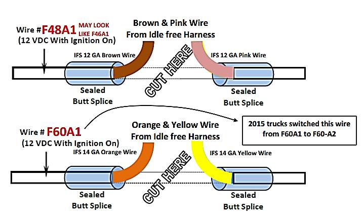
39 OEM Fan Harness Installation The OEM fan harness installation allows the AGM battery bank to directly power the bunk s blower fan and manage all aspects of the bunk heater controls. (show diagram) There is a single wire location (located at the bunk HVAC system) that needs to be routed to the UBB. This varies by truck make and model. Please see instructions for each on the following pages. International LoneStar & ProStar Locate and isolate the H75C (green) wire. It is a heavily insulated 10 gauge wire. Cut the wire allowing adequate length on both sides to perform a butt splice. Turn the ignition to ON position. The side of the cut wire with the 12 VDC power will be butt spliced with the brown APU wire. The other side of the cut wire will be butt spliced to the pink APU wire. Before performing any crimp, turn the ignition to the OFF position Next, locate and isolate the H75V (green) wire. Cut the wire allowing adequate length on both sides to perform a butt splice. Turn the ignition to ON position. The side of the cut wire with the 12 VDC power will be butt spliced with the orange APU wire. The other side of the cut wire will be butt spliced to the yellow APU wire. Before performing any crimp, remember to turn the ignition to the OFF position #61033 REV A 39
40 OEM Fan Harness Installation International LT Wire Connection Location: There are two locations that the wiring has to be routed to from the Under Bunk Box. The first pair of wires needs to be routed to the bunk HVAC unit. It is located on the passenger side, under the bunk mattress support area. The second pair of wires is connected on the driver side of the truck on the back wall of the sleeper, at the bunk HVAC control. Wire Access & Location: Turn ignition key to On position. Ensure bunk HVAC is activated. Confirm bunk blower engages. Turn ignition key to Off position. This is to confirm the bunk HVAC operates before any work is done. See diagram on following page for specific splicing information. BEFORE PERFORMING ANY CRIMP, TURN IGNITION KEY BACK TO OFF POSITION (confirming there is no power available at any wires.) Wire Numbers & Connections: 1 st Pair of Wires (Located at bunk HVAC system, passenger side, under bunk) Turn ignition key to On position. Ensure bunk HVAC is activated. Confirm bunk blower engages. Turn ignition key to Off position. Locate and isolate wire H75C, green in color. This is a heavily insulated, 10 ga wire. Cut wire allowing adequate length of wire on both sides to perform a butt splice. Turn ignition key to On position. The side of the cut wire with 12 VDC power will be butt spliced with the Brown Idle free wire. The other side of this cut wire will have the Pink wire butt spliced to it. BEFORE PERFORMING ANY CRIMP, TURN IGNITION KEY BACK TO OFF POSITION. 2 nd Pair of Wires (Top of bunk HVAC module) The wire needed is in PIN #3 of the HVAC module. Locate and isolate wire H12B. At start of production (Dec 2016), it is purple in color. This may change over time, but it will always be PIN #3, & be labeled H12B. Cut the wire allowing adequate length of wire on both sides to perform a butt splice. Turn ignition key to On position. The side of the cut wire with 12 VDC power will be butt spliced with the Orange Idle Free wire. The other side of this cut wire will have the Yellow wire butt-spliced to it. 3 RD Pair of Wires (NOT USED IN THIS APPLICATION) Use butt splice on end of blue wire, and cover other end of splice. This wire will have 12 Volts DC when thermostat switch is in heat position. #61033 REV A 40

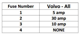
41 OEM Fan Harness Installation Installation Confirmation: Proper wiring can be confirmed AFTER the exterior heater (coolant heater) has been connected electrically and plumbing is completed. The UBB must have all its necessary wiring in place. When this is complete, turn the ignition key to the On position and confirm bunk blower operates as normal. Turn ignition key to Off position and turn Idle Free thermostat to HEAT position. The bunk blower should operate as if the ignition key was in the On position; allowing blower speed control and blend door operation. Each Heater Control Harness bag contains the necessary fuses for the truck the system is being installed in. Remember, EVERY truck will have a 5 amp fuse in position #1 (top) for the thermostat. #61033 REV A 41


42 OEM Fan Harness Installation Freightliner Cascadia: #61033 REV A 42


43 Kenworth T660, T800, W900: OEM Fan Harness Installation #61033 REV A 43


44 OEM Fan Harness Installation Kenworth T680: #61033 REV A 44


45 OEM Fan Harness Installation Mack Pinnacle: #61033 REV A 45


46 OEM Fan Harness Installation Peterbilt 384, 386, 389: #61033 REV A 46

47 OEM Fan Harness Installation Volvo: #61033 REV A 47
48 OEM Fan Harness Installation Peterbilt 579: Wire Connection Location: The Bunk wire looms are located in the driver side cargo area, on the bunk side of the driver side closet, under the hinged mattress support surface and in the driver side bunk HVAC console control. Wire Access & Location: To gain access to the wires, you must locate them within the loom of wires. There are three wires that need to be used. Identify them, and separate them from the other wires to confirm you splice into the correct wires. You will also need to remove the front cover on the HVAC console to gain access to the HVAC control head wiring on the back of this control. Wire Numbers & Connections: 1 st + Pair of Wires (Passenger side under bunk along bunk header above sleeper HVAC system.) Turn ignition key to On position. Ensure bunk HVAC is activated. Confirm bunk blower engages and that the blend door operates. Turn ignition key to Off position. Locate and isolate wire number YEL Cut wire, allowing adequate length of wire on both sides to perform a butt splice. Turn ignition key to On position. The side of the cut wire with 12 VDC power will be butt spliced to the IFS Brown (YEL ) Idle Free Systems harness wire. BEFORE PERFORMING ANY CRIMP, TURN IGNITION KEY BACK TO OFF POSITION. The other side of this cut wire will have the IFS Pink (YEL ) wire butt-spliced to it. See diagram on following pages. #61033 REV A 48

49 OEM Fan Harness Installation Peterbilt 579: 2nd Pair of Wires (Passenger side under bunk along bunk header above sleeper HVAC system.) Turn ignition key to On position. Ensure bunk HVAC is activated. Confirm bunk blower engages and that the blend door operates. Turn ignition key to Off position. Locate and isolate wire number YEL Cut wire, allowing adequate length of wire on both sides to perform a butt splice. Turn ignition key to On position. The side of the cut wire with 12 VDC power will be butt spliced to the IFS Orange (YEL ) Idle Free Systems harness wire. BEFORE PERFORMING ANY CRIMP, TURN IGNITION KEY BACK TO OFF POSITION. The other side of this cut wire will have the IFS Yellow (Yel ) wire butt-spliced to it. 3 rd Pair of Wires (located behind the driver side HVAC control panel) Turn ignition key to On position. Ensure bunk HVAC is activated. Confirm bunk blower engages. Turn ignition key to Off position. The third wire ORN located in the HVAC enclosure behind the HVAC control head leading to the temperature control knob, cut wire to 12 VDC power will splice to IFS Green (ORN ). Turn ignition key to On position. The side of the cut wire with 12 VDC power will be butt spliced to the IFS Green (ORN ) harness wire. The other side will splice to the Blue IFS harness wire. Prior to PERFORMING ANY CRIMP, TURN IGNITION KEY BACK TO OFF POSITION.. The other side will splice to the IFS Blue (ORN ) harness wire. See diagram on following page. Installation Confirmation: Proper wiring by can be confirmed AFTER the exterior heater (Webasto coolant heater) has been connected electrically and plumbing is completed. The UBB must have all its necessary wiring in place as well. When this is complete, turn the ignition key to the On position and confirm bunk blower operates as normal. Turn ignition key to Off position, and turn Idle Free thermostat to Heat position. The bunk blower should operate as if the ignition key was in the On position, allowing blower speed control and blend door operation. #61033 REV A 49

50 OEM Fan Harness Installation Peterbilt 579: #61033 REV A 50

51 Coolant Heater Hose Installation After this installation is complete, the coolant heater will supply coolant to the bunk s heater core. The installation kit will include: ¾ hose, 5/8 hose, hose clamps, hose adapters and cable ties. Coolant Lines extending out the rear of the APU s frame rail unit Locate the coolant hose that supplies coolant to the bunk heater s core from the truck s engine. (There are two hoses that run between the bunk s heater core and the engine. If it is not clear which of the two hoses is supplying coolant from the engine to the bunk, start the engine and hold both hoses. The hose that heats up first is the heater hose. This is the hose used in this installation) Place coolant dam on coolant reservoir, clamp hoses with pinch pliers on either side of the elbow to be removed, or drain the coolant from the system. Cut the coolant hose in between the pinch pliers. Install the supplied rubber elbows to the exposed coolant lines and angle towards the center of the truck. Elbows are 5/8 on one end and ¾ on the other. Make sure you have the 5/8 end on the exposed pipes. Connect the outlet heater hose from the frame rail unit of the APU to the end of the cut hose that connects to the inlet on the bunk heater core using a hose clamp Connect the inlet heater hose from the frame rail unit of the APU to the other end of the cut hose which is attached to the engine using a hose clamp Remove the pinch pliers or coolant dam #61033 REV A 51


52 Before Installation: After Installation: #61033 REV A 52
53 Fuel Standpipe Installation: Fuel Line & Standpipe Installation Cut the fuel standpipe to app. 2 from the bottom of the fuel tank. Be sure to account for the fittings on top of the tank. Make sure you angle the cut to prevent clogging. Remove burrs from the end cut. Use the ¼ or ½ spare port on the fuel tank if available and install the supplied adapters in the port. If a spare port is not available, drill a 1 hole on the top of the tank. Assemble the tankboss and the fuel standpipe and install. (show diagram) Connect the fuel line from the fuel pump to the fuel standpipe using the rubber connectors and clamps. Route and secure the fuel line from the fuel tank to the heater. Fuel Line Connections: Route a fuel line between the truck s fuel pickup tube and the coolant heater s fuel pump Secure the fuel lines every 12 and keep away from hot exhaust and moving parts such as the drive shaft. Use the supplied hose clamps to secure all fuel line connections. (see diagram) #61033 REV A 53

 Remove the fuse from the fuse holder. Bolt the 5/16 th lug from cable 1 to one of the fuse holder s terminals.")
 Bolt the cable end to the remaining terminal on the fuse holder. Do not insert the fuse yet.")
54 DC Cables Installation We will be installing 5 cables and a fuse with fuse holder in this step. Overview: The Connection Hub for all harnesses is the UBB or Under Bunk Box. The UBB includes connection points on the back rear corner of the enclosure. The connection hub contains connection sockets for the following connectors: 1. Shore Power 2. Evaporator 3. UBB to APU Harness 4. Volt Meter 5. Ignition 6. Thermostat 7. OEM HVAC VAC, 10 AMP 9. DC Cables from Battery Box or APU Cable 1: Part number: (red cable) Remove the fuse from the fuse holder. Bolt the 5/16 th lug from cable 1 to one of the fuse holder s terminals. Connect the 3/8 th cable end to the positive post of one of the truck batteries Secure the fuse holder in the truck s battery box. Cable 2: Part number (red cable) Bolt the cable end to the remaining terminal on the fuse holder. Do not insert the fuse yet. Route cable 2 between the truck s battery box and the APU s batteries (AGM battery connection). Cut to length. Attach the green camlock connector to the other end of cable 2. Plug the green connector on cable 2 into the green panel mount connector on the APU s frame rail unit. Twist the connector clockwise. Ensure that the connector cannot be pulled from the panel mount. Camlock Connector #61033 REV A 54

55 Cable 3: Part number (red cable) DC Cables Installation Attach one end of cable 3 onto the red stud on the UBB. Route this cable through the floor collar to the APU unit s panel mount, located on the frame rail unit Cut the cable to length and attach the red twist lock connector to the end of the cable. Plug the red camlock connector to the red panel mount connector on the APU s frame rail unit. Turn clockwise. Ensure that the connector cannot be pulled from the panel mount. Cable 4: Part number (black cable) Bolt the 3/8 th cable end to a negative post on one of the truck s batteries. Route the cable to the frame rail unit s panel mount. Cut the cable to length. Attach the black twist lock connector to the end of the cable. Plug the black camlock connector into the bottom black panel mount connector. Turn clockwise and ensure that the connector cannot be pulled from the mount panel. Cable 5: Part number (black cable) Attach one end of cable 5 to the black stud on the UBB Route this cable through the floor collar to the APU s frame rail unit s panel mount. Cut the cable to length. Attach the black camlock connector to the end of the cable. Plug the twist lock connector into the top black panel mount connector and turn clockwise. Finally, insert the fuse into the fuse holder. Ensure all cables are secured along their routes and that all twist lock connectors are matched to the correct color on the panel mount of the frame rail unit. #61033 REV A 55

56 Camlock Connector Installation #61033 REV A 56

57 Camlock Connectors Installation #61033 REV A 57

58 Camlock Connectors Installation #61033 REV A 58

59 Camlock Connectors Installation #61033 REV A 59
60 Reefer Link Installation Installation Overview: The Reefer Link XD installation procedures include installing components onto the truck and onto a reefer trailer. The truck s portion of the Reefer Link installation will include: 1. Hanging a connector on the back side of the bunk, near the electrical and air line connections. 2. Cutting a two wire cable (to length) that will be connecting to the APU (battery connection) and the connector newly installed on the back side of the bunk (1.). The trailer s portion of the Reefer Link installation will include: 1. Hanging a connector onto the nose of the reefer unit. 2. Cutting a two wire cable (to length) that will be connecting to the reefer s negative battery post (black cable) and the reefer s alternator, positive post (red cable). The installation process will include crimping cable ends onto the newly fitted (cut) cables. The installation process will also include installing an inline fuse on the positive cable between the APU and the back of bunk connection point. #61033 REV A 60

 using a knife. Be careful not to separate the wires in a way that exposes the internal cable wires.")
 from the kit based on the size of the connector bolts on the back of the connector body (do not use the 3/8 battery lugs).")
61 Reefer Link Installation Reefer Link Truck Installation: Open the Reefer Link Kit #91412 and lay out the parts. Locate the bracket and the connector body. Determine the mounting location on the back of truck/bunk that the Reefer Link body and bracket will be located. Determine the orientation of the connector body into the bracket, based on where the assembly will be located on the back of the bunk. Locate the parallel red/black cables. Take one end of the cable and separate the black and red wires (about 10 inches) using a knife. Be careful not to separate the wires in a way that exposes the internal cable wires. Strip both wires back 1. Place a cut piece of red heat shrink onto the red wire and place a cut piece of black heat shrink onto the black wire. Locate the correct size lugs (2) from the kit based on the size of the connector bolts on the back of the connector body (do not use the 3/8 battery lugs). Crimp the cable lugs onto the red and black cables. Move the heat shrink up to the spot where the new crimp is completely covered. Shrink the heat shrink onto the cable end using a heater gun. Install the RED lug onto the back of the connector body (face down) locating the red lug on the bolt that screws into the positive (+) receptacle. Install the BLACK lug onto the back of the connector body (face down) locating the black lug on the bolt that screws into the negative (-) receptacle. Install the mounting bracket onto the back of the connector body using the two bolts and nuts supplied. Route the parallel cable, attached to the rear of the connector body, to the back side of the APU s frame rail unit. #61033 REV A 61


62 Reefer Link Installation Remove the plug and/or enter the battery box with the parallel cable. Cut the parallel cable to length understanding that the positive cable needs to reach the positive post of the nearest battery. A fuse will also be installed near the positive post of this battery. Separate the black and red wires using a knife. Be careful not to separate the wires in a way that exposes the internal cable wires (along the cut). Separate the wires back to the box entry point. Installing the Fuse Cut the red cable about 12 leaving enough cable to be able to crimp a lug onto the cut end of the cable. Locate the small fuse holder and fuse from kit # Locate two lugs from the kit that fit snuggly onto the small fuse holder terminals. Slide a piece of red heat shrink onto the red cable that was cut (runs to the box entry point). Crimp the fuse lug onto the cable end, place the heat shrink over the crimp and heat/melt the heat shrink in place. Cut a red (positive) cable that will easily reach the battery s positive post from the fuse terminal. Crimp the fuse lug onto the cable end, place the heat shrink over the crimp and heat/melt the heat shrink in place. Slide a piece of red heat shrink onto the fuse to battery cable (to the battery post, positive). Crimp a 3/8 lug onto the opposite cable end, place the heat shrink over the crimp and heat/melt the heat shrink in place. Slide a piece of black heat shrink onto the black battery cable (to the battery post, negative). Crimp a 3/8 lug onto the black cable end, place the heat shrink over the crimp and heat/melt the heat shrink in place. Install the fuse holder between the two red cables & install the fuse and secure with nuts. Place the cover onto the fuse holder. Install the red cable onto the positive post and install the black cable onto the negative post. Secure the added cables with tie straps between the battery connections and the connector body and bracket. #61033 REV A 62


63 Reefer Link Installation Reefer Link Trailer Installation Open the kit #91413 and lay out the parts. Locate the box and the connector body, & the connector body faceplate. Determine the mounting location, under the reefer unit, that the Reefer Link connection box will be located. Mount the box so that the cable leaves the box on the bottom. Do not mount the box with the cable opening facing up. The parallel cable will leave the box on the bottom and will take a route up the front of the trailer to the reefer s battery and the reefer s alternator. Locate the parallel red/black cable from the kit. Take one end of the cable and separate the black and red wires (about 10 inches) using a knife. Be careful not to separate the wires in a way that exposes the internal cable wires. Strip both wires back 1. Place a cut piece of red heat shrink onto the red wire and place a cut piece of black heat shrink onto the black wire. Locate the correct size lugs (2) from Kit #91413 based on the size of the connector bolts on the back of the connector body (do not use the 3/8 battery lugs). Crimp the cable lugs onto the red and black cables. Move the heat shrink up to the spot where the new crimp is completely covered. Shrink the heat shrink onto the cable end using a heat gun. Locate the face plate & gasket from Kit #91413 and install the connector body onto the face plate, cutting the gasket to fit. Install the connector body/face plate assembly (with gasket) into the box orientating the flap to lift up with the cable leaving the box at the bottom of the assembly. Install the rubber grommet onto the parallel cable set, about 12 inches. Install the RED lug onto the back of the connector body (face down) locating the red lug on the bolt that screws into the positive (+) receptacle. Install the BLACK lug onto the back of the connector body (face down) locating the black lug on the bolt that screws into the negative (-) receptacle. Install the connector body/face plate assembly into the enclosure Position the rubber grommet up the cables to the seat in the base of the enclosure. #61033 REV A 63
. The parallel cable should enter the reefer unit against the back wall.")

64 Reefer Link Installation Secure the enclosure to the front of the reefer trailer, under the reefer unit. Route the parallel cable (exiting the enclosure) to the inside of the reefer unit. Secure the cable in place, under the reefer unit, using the P Clips (supplied in Kit #91413). The parallel cable should enter the reefer unit against the back wall. Once the parallel cable has entered the reefer unit, the cable can be separated into red and black cables by cutting. Be careful when splitting the cable not to cut the cable in a way that exposes the copper wire. Any exposed copper wire needs to be repaired with tape or heat shrink. The black cable will end up connecting to the negative reefer battery post. The positive cable will be routed to the reefer s alternator. About 12 inches from the reefer s alternator positive post a fuse will be located. This fuse location will require a positive (red cable) to be made from the cable left over during this process. Route the (split) black cable to the reefer s battery. Cut the black cable leaving enough cable to easily reach the negative battery post. Place a cut piece of black heat shrink onto the black cable. Source a 3/8 cable lug from kit # Crimp the 3/8 cable lug unto the end of the black cable. Move the heat shrink up the cable to cover the crimp. Shrink the black heat shrink in place using a heat gun. Secure the black cable in place between the battery and the reefer box cable entry point. Route the red cable from the reefer cable entry point to the positive connection point on the reefer s alternator. Cut the cable, leaving plenty of cable so as to be able to easily reach the alternators positive post, keeping in mind the act of securing the cable after the installation is complete. Cut 12 inches from the cable. Installer will use this 12 inch cable to create an alternator connection and a fuse connection. Locate the small fuse holder and fuse from Kit # Locate two lugs from Kit #91413 that fit snuggly onto the small fuse holder terminals. Slide a piece of red heat shrink onto the red cable that was cut (runs to the box entry point). Crimp a fuse lug onto the cable end, place the heat shrink over the crimp and heat/melt the heat shrink in place. #61033 REV A 64

65 Reefer Link Installation Slide a piece of red heat shrink onto the fuse to battery cable (to the battery post, positive). Crimp a #10 lug onto the opposite cable end, place the red heat shrink over the crimp and heat/melt the heat shrink in place. Crimp a fuse lug onto the cable end, place the red heat shrink over the crimp and heat/melt the heat shrink in place. Install the fuse holder between the two red cables & install the fuse and secure with nuts. Place the cover onto the fuse holder. Install the red cable onto the alternator s positive post. Secure the newly installed cables with tie straps. #61033 REV A 65
eapu Reference Guide System Component Information (For serial numbers starting with 37)
") eapu Reference Guide System Component Information (For serial numbers starting with 37) #68004 REV B December 2018 Table of Contents Topic Battery Separator 3 DC Voltage 6 Thermostat 7 Power Converter
eapu Reference Guide System Component Information (For serial numbers starting with 37) #68004 REV B December 2018 Table of Contents Topic Battery Separator 3 DC Voltage 6 Thermostat 7 Power Converter
Idle Free Systems, Inc. Reference Guide System Component Information
 Idle Free Systems, Inc. Reference Guide System Component Information #68004 REV 3 #68004 REV 3 Idle Free Reference Sheets System Components & Trouble shooting Table of Contents RF # 101.0 102.0 103.0 104.0
TABLE OF CONTENTS INTRODUCTION 3. INSTALLATION PROCEDURES Air Conditioner Location 4. A/C Ducting Installation 5
 585474 1 TABLE OF CONTENTS SECTION PAGE INTRODUCTION 3 INSTALLATION PROCEDURES Air Conditioner Location 4 Air Conditioner Mounting 4 A/C Ducting Installation 5 Power Kit Installation (Batteries). 5 Separator...
SCION xd INTERIOR LIGHTING UPGRADE Preparation
 Preparation Part Number: PTS21-52085 Light Guide Kit Contents Item # Quantity Reqd. Description 1 1 Controller Board, 4 color programmed w/ Bracket 2 1 RGB, LED Engine wire harness 3 2 14mm Light Rod,
Air Conditioner for M915 A0/A1 Truck
 RD-2-4530-0 Air Conditioner for M915 A0/A1 Truck INSTALLATION INSTRUCTIONS Install refrigerant compressor per instructions provided with compressor mount kit. CAUTION: Edges of sheet metal can be sharp!
INSTALLATION INSTRUCTIONS FUEL SURGE TANK KIT
 INSTALLATION INSTRUCTIONS FUEL SURGE TANK KIT BMW E46 3-Series, Excl Convertible Document: 19-0056 Support: info@radiumauto.com Relieve fuel pressure in vehicle before beginingthe installation. Disconnect
Installation Instructions
 Installation Instructions Jeep JK Unlimited (2007 Present) Mounting Bracket and Air Line System Kit for ARB On-Board Twin Air Compressor (CKMTA12) Made in the USA Kit Contents: 1 Bracket for ARB Compressor
Installation Instructions
 Installation Instructions Jeep JK 2-Door (2011 Present) Mounting Bracket and Air Line System Kit for ARB On-Board Twin Air Compressor (CKMTA12) Made in the USA Kit Contents: 1 Flat Bracket 1 Formed Bracket
WPS-104 Heater Installation Instructions For 500EFI, 700 XP, & Crew Applications
 WPS-104 Heater Installation Instructions For 500EFI, 700 XP, & Crew Applications ORDER OF INSTALLATION FOR A COMPLETE ENCLOSURE OF A RANGERWARE WPS (Weather Protection System) IS AS FOLLOWS: 1. Heater
2-row and All-row systems included.
 Ag Leader Technology Cotton Picker Installation Installation Instructions for John Deere cotton picker models: 2-row and All-row systems included. IMPORTANT: Ensure the model numbers shown above correspond
Model 377, 379, 386, 388, Sleeper no window
 Installation Manual Model 377, 379, 386, 388, 389 63 Sleeper no window 2390 Blackhawk Road P.O. Box 6007 Rockford, IL 61125 www.nitesystem.com 1-866-204-8570 NITE Plus Installation Procedures 1-2 Table
INSTALLATION INSTRUCTIONS FOR THE TOMAHAWK ELECTRIC REVERSE
 INSTALLATION INSTRUCTIONS FOR THE TOMAHAWK ELECTRIC REVERSE LAST UPDATED: April 2018 Thank you for choosing the Motor Trike Electric Reverse. We ask that you read the directions before you start and follow
JODALE PERRY. Parts List & Mounting Instructions. Jacobsen HR9016 JDP BUILT FOR LIFE
 JODALE PERRY Parts List & Mounting Instructions Jacobsen HR9016 JDP BUILT FOR LIFE Jacobsen HR9016 Mounting Instructions Standard Parts 1 - LH Rear Mounting Bracket 1 - RH Rear Mounting Bracket 1 - Front
2015 Mustang Lightbar (All Models) CDC#
 CDC#") 2015 Mustang Lightbar (All Models) CDC# 1511-7000-01 Components: 1 CDC Lightbar Note: READ instructions before starting installation!!! CDC Part# Driver side bracket 0511-6001-05 Passenger side bracket
2015 Mustang Lightbar (All Models) CDC# 1511-7000-01 Components: 1 CDC Lightbar Note: READ instructions before starting installation!!! CDC Part# Driver side bracket 0511-6001-05 Passenger side bracket
Jeep Wrangler TJ. Complete Air Conditioning System. Slide Control Head. Installation instructions
 WWW.JEEPAIR.COM 1996-1998 Jeep Wrangler TJ Complete Air Conditioning System Slide Control Head Installation instructions Kit Information After 1994 every vehicle was designed for R134a refrigerant. The
Adjustable Light Kits E-Z-Go TXT All Models Installation Instructions
 Adjustable Light Kits E-Z-Go TXT All Models 1996-2013 Installation Instructions Caution: Please read through the instructions carefully. Before starting this project, remove the system s positive and negative
INSTALLATION AND USER MANUAL
 INSTALLATION AND USER MANUAL SDKIT-730 & SDKIT-734 100% Bolt-On 150 PSI Train Horn System for 2011-2015 F-250 & F-350 Super Duty P/N SDKIT-730 P/N SDKIT-734 Thank you for purchasing a Kleinn Air Horns
1. Disconnect the battery. This is important! This will prevent air bag deployment.
 PARTS PACKING LIST Evaporator assembly Drain tube Plastic air plug Hardware package 11040 3601 W. Clarendon Phoenix, Arizona 85019 (602) 233-0090 800-648-4475 www.ackits.com 2003-4 Jeep Wrangler EVAPORATOR
TABLE OF CONTENTS INTRODUCTION.. 3. A/C Ducting Installation. Power Kit Installation (Batteries)...5 OPERATION MANUAL 7-8 TOOLS LIST..
...5 OPERATION MANUAL 7-8 TOOLS LIST..") 585457 1 TABLE OF CONTENTS SECTION PAGE INTRODUCTION.. 3 INSTALLATION PROCEDURES Air Conditioner Location...4 Air Conditioner Mounting 4 A/C Ducting Installation...5 Power Kit Installation (Batteries)...5
585457 1 TABLE OF CONTENTS SECTION PAGE INTRODUCTION.. 3 INSTALLATION PROCEDURES Air Conditioner Location...4 Air Conditioner Mounting 4 A/C Ducting Installation...5 Power Kit Installation (Batteries)...5
PFadvantage MF 6850/6855; Ideal 9080/9090
 MF 6850/6855; Ideal 9080/9090 Note: Indented items indicate parts included in an Quantity by Model assembly listed above MF Ideal Part Name/Description Part Number 6850 6855 9080 9090 Instruction Kit MF
LGT-306L / LB Club Car Precedent LED Light Bar Bumper Kit Installation Instructions
 LGT-306L / LB Club Car Precedent LED Light Bar Bumper Kit Installation Instructions Caution: Please read through the instructions carefully. Before starting this project, remove the system s positive and
C FORD F250 / F L POWERSTROKE DIESEL WITH AUTOMATIC TRANSMISSIONS ONLY
 EXHAUST BRAKES C40019 1999-2003 FORD F250 / F350 7.3L POWERSTROKE DIESEL WITH AUTOMATIC TRANSMISSIONS ONLY Getting Started Thank you and congratulations on your purchase of a Pacbrake exhaust retarder.
INSTALLATION INSTRUCTIONS FOR COZY CAB A-1 AIR CONDITIONING KIT
 INSTALLATION INSTRUCTIONS FOR COZY CAB A-1 AIR CONDITIONING KIT 05-11 INSTALLATION INSTRUCTIONS A-12235 Air Conditioner Kit Cab set up instructions; This air conditioning kit is designed to be used with
INSTALLATION INSTRUCTIONS
 28 INSTALLATION INSTRUCTIONS SECTION - AIR SPRING SECTION 2 - AIR ACCESSORY 2-5 ! IMPORTANT PLEASE DON T HURT YOURSELF, YOUR KIT OR YOUR VEHICLE. TAKE A MINUTE TO READ THIS IMPORTANT INFORMATION. This
GENUINE PARTS INSTALLATION INSTRUCTIONS
 GENUINE PARTS INSTALLATION INSTRUCTIONS 1. 2. 3. 4. DESCRIPTION: Accent light Kit APPLICATION: Infiniti JX (2013) PART NUMBER: 999F3 YY000 - Universal Accent Lighting Kit. KIT CONTENTS: Item QTY Description
INSTALLATION INSTRUCTIONS
 2807 INSTALLATION INSTRUCTIONS SECTION - AIR SPRING SECTION 2 - AIR ACCESSORY -6 ! IMPORTANT PLEASE DON T HURT YOURSELF, YOUR KIT OR YOUR VEHICLE. TAKE A MINUTE TO READ THIS IMPORTANT INFORMATION. This
LGT-312L E-Z-Go TXT Light Bar Bumper Kit Installation Instructions
 LGT-312L E-Z-Go TXT 2014+ Light Bar Bumper Kit Installation Instructions Caution: Please read through the instructions carefully. Before starting this project, remove the system s positive and negative
INSTALLATION & OWNER S MANUAL
 INSTALLATION & OWNER S MANUAL CAB INSTALLATION INSTRUCTIONS JOHN DEERE 3000 SERIES (4200/4300/4400) (4210/4310/4410) & (3120/3320/3520/3720) HARD SIDED CAB ENCLOSURE (p/n 1JD3520AS) SOFT SIDED CAB ENCLOSURE
INSTALLATION INSTRUCTIONS
 Rear Vision System Tailgate Emblem Camera Mirror Display 2009-Current Ford F-150 and 2010-Current Super Duty (Kit part number 1008-9527) Kit Contents: Mirror Tailgate Emblem Mount with Camera Interior
GENUINE PARTS INSTALLATION INSTRUCTIONS
 GENUINE PARTS INSTALLATION INSTRUCTIONS 1. 2. 3. 4. DESCRIPTION: Accent light Kit APPLICATION: Versa (2012) PART NUMBER: 999F3 AW008 - Universal Accent Lighting Kit. KIT CONTENTS: Item QTY Description
INSTALLATION INSTRUCTIONS
 INSTALLATION INSTRUCTIONS FUEL SURGE TANK INSTALLATION KIT 1999-2006 BMW E46 COUPE Document# 19-0056 Support: info@radiumauto.com Note: This kit was designed for a standard single pump Radium Engineering
1963 GEN IV SUREFIT VINTAGE AIR CONDITIONING INSTALLATION
 by Randy Irwin 1963 GEN IV SUREFIT VINTAGE AIR CONDITIONING INSTALLATION Randy Irwin - Technical Writer Randy has been involved in the Chevy parts business for over 30 years. He is a wizard at creating,
Installation and Commissioning of Auxiliary Power Unit
 Models PC6012 PC6013 PC6014 PC6015 PC6022 PC6023 PC6024 Installation and Commissioning of Auxiliary Power Unit 30-871-21 Rev. E Warning & Cautions Vehicles with longer wheel bases should have the APU mounted
Part Name/Description Part Number Quantity Instruction Kit Metalfor Flow Sensor
 NOTE: Indented items indicate parts included in an assembly listed above Part Name/Description Part Number Quantity Instruction Kit Metalfor 4101091 1 Flow Sensor 4001356 1 Deflector plate 2000612-1 1
INSTALLATION INSTRUCTIONS
 INSTALLATION INSTRUCTIONS FUEL SURGE TANK INSTALL KIT Honda S2000 Document# 19-0063 Support: info@radiumauto.com WARNING: DO NOT SMOKE WHILE WORKING ON FUEL SYSTEMS. KEEP SPARKS AND OPEN FLAMES AWAY FROM
GENUINE PARTS INSTALLATION INSTRUCTIONS
 GENUINE PARTS INSTALLATION INSTRUCTIONS 1. 2. 3. 4. DESCRIPTION: Accent light Kit APPLICATION: R42H (2011) PART NUMBER: 999F3 AW000 - Universal Accent Lighting Kit. KIT CONTENTS: Item QTY Description Service
C40008 & C40009 EXHAUST BRAKES
 EXHAUST BRAKES C40008 & C40009 1995 2003 Ford F250 / F350 7.3 L Powerstroke Diesel with manual transmissions 1995 1998 Ford F250 / F350 7.3 L Powerstroke Diesel with automatic transmission* *Requires the
C15C C15C. Page 1 of 20
 2 x Lid Front Hinge 1135 8 x M8 Bolt 8 x M8 Washer (3mm Thick) 4 x M6 Large washers 4 x M6 Spring washers 4 x M6 x 40mm Bolts 6 x M6 20mm Bolts 6 x M6 Washers 20 x Screws 2 x Lid mount gas strut bracket
PERFECT FIT SERIES IN-DASH HEAT/ COOL/ DEFROST MUSTANG
 specializing in AIR CONDITIONING, PARTS AND SYSTEMS for your classic vehicle PERFECT FIT SERIES IN-DASH HEAT/ COOL/ DEFROST 1969-70 MUSTANG CONTROL & OPERATING INSTRUCTIONS The controls on your new Perfect
Pump Gas Instructions for Polaris And 800 Models. Important Information before Installing This System:
 Pump Gas Instructions for Polaris 600 700 And 800 Models Important Information before Installing This System: Before you begin your turbo install, read through these instructions to determine if you are
8436, 8437, 8438, 8439, 8442, 27480, 27780, 28028, & ISOLATION MODULE ELECTRICAL SYSTEM
 September 11, 2003 Lit. No. 27808 8436, 8437, 8438, 8439, 8442, 27480, 27780, 28028, & 28400 ISOLATION MODULE ELECTRICAL SYSTEM Installation Instructions Read this document before installing the snowplow.
GENUINE PARTS INSTALLATION INSTRUCTIONS
 GENUINE PARTS INSTALLATION INSTRUCTIONS 1. 2. 3. 4. DESCRIPTION: APPLICATION: PART NUMBER: KIT CONTENTS: Accent light Kit Pathfinder 999F3 XZ000 - Accent Lighting Kit. Item QTY Description Service Part
Installation Instructions for John Deere cotton picker models: 9986 & 2-row and All-row systems included.
 Ag Leader Technology Cotton Picker Installation Installation Instructions for John Deere cotton picker models: 9986 & 9996 2-row and All-row systems included. IMPORTANT: Ensure the model numbers shown
TOYOTA FJ CRUISER 2007 AUXILIARY LIGHTS Preparation
 TOYOTA FJ CRUISER 2007 AUXILIARY LIGHTS Preparation Part Number: PT297-35061 Kit Contents Item # Quantity Reqd. Description 1 2 Driving Lamp Assembly 2 1 Switch Harness 3 1 Lamp Harness 4 2 Stone Shield
SHELBY GT500
 2007-2009 SHELBY GT500 Removal of Factory Unit WARNING: 1. Radiator fluid must be handled properly. Please observe local ordinances with regards to handling and disposal. 2. Allow vehicle and components
Fitting Instructions. Revo MQB Golf/GTi/Octavia/Leon Intercooler. Recommended Tools. Contents RV581M Dealer installation advised.
 RV581M100100 Recommended Tools Contents No. Description Tools Size Intercooler Torx Bit T25, T30 Bracket Kit llen Key 4, 5 mm Silicone Hoses Socket 7, 10, 16, 19 mm Hose Clamps Flat Head Screwdriver Small,
TOYOTA RAV4/HV INTERIOR LIGHT KIT Preparation
 Preparation Part Number: PT413-42130 Kit Contents Item # Quantity Reqd. Description 1 1 Wire Harness 2 3 Hardware Bag Contents Item # Quantity Reqd. Description 1 20 Cable Tie 2 2 Scotchlok 3 2 Foam Pad
PRODUCT: Install Instructions, MV-1 C/O Std, With Aux Fan RELEASE DATE: 2/28/14 REVISION DATE: 9/30/2014 PART NUMBER: Rev C
 Parts List (1) 01 000 027 Switch, 4 Position Blower (1) 04 000 007 Hose, 1/2 ID Drain, 6 (1) 01 000 087 Harn, Resistor (1) 04 000 078 Tube, Convo 1/2 x 24 (2) 01 000 136 Relay, 40 Amp (1) 04 000 015 Hose,
Jeep Wrangler TJ 4.0 LITER Installation instructions
 www.jeepair.com 2002-2004 Jeep Wrangler TJ 4.0 LITER Installation instructions Kit Information These directions are for 2002-2006 model Jeep Wranglers. After 1994 every vehicle was designed for R134a refrigerant.
Installation Instructions Table of Contents
 Installation Instructions Table of Contents Pre- Installation of Garage Storage Lift 2 Layout the Garage Storage Lift 3 Installing the strut Channels 3 Install the Drive Assembly 5 Install the Drive Shaft
PRODUCT SAFETY NOTICE
 PRODUCT SAFETY NOTICE Congratulations. This vehicle has been equipped with a Firestone air suspension system. This suspension will enhance the vehicle s handling when loaded, however, the vehicle s performance
INSTALLATION INSTRUCTIONS
 INSTALLATION INSTRUCTIONS Part# 22-2719 Complete Mounting System for Dual Viair Compressors For the most up-to-date instructions please visit www.updownair.com www.updownair.com 833-226-4863 I M P O R
Your Legal Fuel Tank Source.
 February 23, 2015 IS# 808 Page 1 of 13 THANK YOU FOR PURCHASING A TRANSFER FLOW 40 GALLON TOOLBOX REFUELING SYSTEM. PLEASE READ THE FOLLOWING PROCEDURES CAREFULLY BEFORE STARTING THE INSTALLATION. CAUTION:
GENUINE PARTS INSTALLATION INSTRUCTIONS
 GENUINE PARTS INSTALLATION INSTRUCTIONS 1. 2. 3. 4. DESCRIPTION: APPLICATION: PART NUMBER: KIT CONTENTS: Accent light Kit Versa Note 999F3 4Z000 - Accent Lighting Kit. 999Q9 AY000 - Accessory Service Connector
Rostselmash Torum 740
 Note: Indented items indicate parts included in an assembly listed above Quantity by Model Part Name/Description Part Number 740 Combine Kit Torum 740 4100762 1 Threaded Arm Assembly 2000311-2 1 Header
TOYOTA SIENNA TRAILER WIRE HARNESS Preparation
 Preparation Part Number: PT791-08150 (non-se) PT791-08102 (SE only) Kit Contents Item # Quantity Reqd. Description 1 1 Trailer Module Harness 2 1 4-Flat Harness 3 1 Battery Power Wire Harness 4 1 Mounting
TOYOTA im INTERIOR LIGHT KIT Preparation
 Preparation Part Number: PT922-12170 Kit Contents Item # Quantity Reqd. Description 1 1 Main Wire Harness 2 1 Switch 3 1 Switch Header 4 1 ECU 5 1 ECU Bracket 6 1 Hardware Kit 7 1 Instruction Card 8 1
OIL COOLER KIT INSTALLATION INSTRUCTIONS PART NUMBER D
 OIL COOLER KIT INSTALLATION INSTRUCTIONS PART NUMBER D570-0904 APPLICATION: 2011-2012 E90 335i/xi (N55 engine) with BMW standard bumper and with stock oil cooler Congratulations for being selective enough
Instructions for 2-row monitoring only
 Installation Instructions for CaseIH cotton picker models: Instructions for 2-row monitoring only Ensure the model numbers shown above correspond to the machine model. If you receive the incorrect installation
BLACKBIRD INSTALLATION SUPPLEMENT
 BLACKBIRD INSTALLATION SUPPLEMENT FOR 2003-7 FORD 6.0 LITER DIESEL SINGLE ALTERNATOR F-350, F-450, F-550, EXCURSION VERSION 7-07 Parts Description Blackbird Wiring Manual Installation Supplement 6.0 Liter
Installation Manual #
 Final 10/01/08 Installation Manual # 585416 T600, T800 and W900 Bergstrom, Inc. 2390 Blackhawk Road P.O. Box 6007 Rockford, IL 61125 www.nitesystem.com 1-866-204-8570 Table of Contents Introduction Before
Thank you for purchasing the Craven Speed FlexPod Complete Gauge Pod Kit For R56, R58, R59, R60 with Refresh Engines (2011+)
") Thank you for purchasing the Craven Speed FlexPod Complete Gauge Pod Kit For R56, R58, R59, R60 with Refresh Engines (2011+) Before You Start Please read instructions completely before installing. These
Thank you for purchasing the Craven Speed FlexPod Complete Gauge Pod Kit For R56, R58, R59, R60 with Refresh Engines (2011+) Before You Start Please read instructions completely before installing. These
GENUINE PARTS INSTALLATION INSTRUCTIONS
 GENUINE PARTS INSTALLATION INSTRUCTIONS 1. 2. 3. DESCRIPTION: APPLICATION: PART NUMBER: Accent light Kit Cube (MY2013+) 999F3 AW000 - Universal Accent Lighting Kit. 4. KIT CONTENTS: Item QTY Description
INSTALLATION INSTRUCTIONS
 Rear Vision System Tailgate Handle Camera Mirror Display 2004-2014 Ford F-150 and 2008-2015 Ford Super Duty (Kit part numbers 9002-9521) Kit Contents: Mirror Tailgate Handle with camera and harness Interior
INSTALLATION & OWNER S MANUAL
 Rev. C p. 1 of 21 INSTALLATION & OWNER S MANUAL F5205 HARD SIDED CAB KIT INSTALLATION & OWNER S MANUAL The contents of this envelope are the property of the owner. Be sure to leave with the owner when
General Applicability Note: Recommended Tools. Personal & Vehicle Protection Safety Goggles Seat Covers Floor Covers Special Tools. Installation Tools
 TOYOTA HIGHLANDER/HIGHLANDER HV 2008- Preparation Part #: PT923-00111 Conflicts: JBL Audio, Factory Navigation NOTE: Part number of this accessory may not be the same as the part number shown. Kit Contents:
Instructions for 2-row monitoring only
 Installation Instructions for CaseIH cotton picker models: Instructions for 2-row monitoring only CAUTION: Ensure the model numbers shown above correspond to the machine model. If you receive the incorrect
Depress each tab as you pull the bezel off. The bezels are tight. L.H. shown.
 2013-2014 Ford Mustang V6 & Boss 302 Lower Valance Fog Light Kit Parts List: Quantity: Tool List: Fog light & bulb with bracket 2 Flat head & Phillips screwdriver Black bezels 2 Ratchet & Socket set OR
INSTALLATION & OWNER S MANUAL
 1 of 18 INSTALLATION & OWNER S MANUAL (*Not including cab & other accessories) A/C Alternator Kit: Yamaha Drive & Drive2 P/N: 1ACYDR2DRK Recommended it be installed with Curtis Cab: Sandstone (p/n 1GCYD1-A,
Installation Instructions
 Installation Instructions www.bestop.com - We re here to help! Visit our web site and click on Ask a Question INSTALLATION TIME SKILL LEVEL Automatic Retracting Running Board Vehicle Application Chevy
TOYOTA VENZA 2009 TRAILER WIRE HARNESS Procedure
 Part Number: PT791-0T099 Kit Contents Item # Quantity Reqd. Description 1 1 Trailer Wire Harness Module 2 1 4-Flat Harness 3 1 Battery Power Wire Harness 4 1 Mounting Bracket, 4-Flat 5 2 Screw #10-24 6
Conflicts: Vehicles without a sunroof Vehicles with a single sunroof
 Toyota Sienna (Dual Sunroof) 2011-10.2 Overhead Video Part Number: 00016-00110 00016-00110-17 Fit Kit 00016-00120 00016-00120-17 Fit Kit Accessory Code: ED5 Conflicts: Vehicles without a sunroof Vehicles
Installation Manual #
 FINAL 10/06/08 Installation Manual #1000067001 Cascadia Under Bunk Mounting Bergstrom, Inc. 2390 Blackhawk Road P.O. Box 6007 Rockford, IL 61125 www.nitesystem.com 1-866-204-8570 Table of Contents Introduction
LGT-311L Bumper LED Light Kit EZ-Go RXV Installation Instructions
 LGT-311L Bumper LED Light Kit EZ-Go RXV Installation Instructions Caution: Please read through the instructions carefully. Before starting this project, remove the system s positive and negative connections
Special Note About The JDM High Performance Water Pump:
 Page 1 of 30 JDM Engineering, Inc. home Call Us! 732-780- 0770 back to Installation Instructions Electric Fan Upgrade Kit Electric Fan Wiring Diagram Thank you for your purchase of the JDM Engineering
FACTORY AIR CONVERSION HEAT/ COOL/ DEFROST CHEVROLET CHEVELLE
 specializing in AIR CONDITIONING, PARTS AND SYSTEMS for your classic vehicle FACTORY AIR CONVERSION HEAT/ COOL/ DEFROST 1970-72 CHEVROLET CHEVELLE CONTROL & OPERATING INSTRUCTIONS The controls on your
TOYOTA VENZA 2009 TRAILER WIRE HARNESS Procedure
 Part Number: PT791-0T099 Kit Contents Item # Quantity Reqd. Description 1 1 Trailer Wire Harness Module 2 1 4-Flat Harness 3 1 Battery Power Wire Harness 4 1 Mounting Bracket, 4-Flat 5 2 Screw #10-24 6
INSTALLATION INSTRUCTIONS
 INSTALLATION INSTRUCTIONS FUEL SURGE TANK INSTALLATION KIT 1999-2006 BMW E46 COUPE Document# 19-0056 Support: info@radiumauto.com Note: This kit wasn t designed for a FST-R, but can be accomplished. 1.
Installation Manual Blackhawk Road Rockford, IL
 Installation Manual 2390 Blackhawk Road Rockford, IL 61072 815-874-7821 www.bergstrominc.com Table of Contents Introduction Before You Start Parts List Tools Required Installation Procedures Electrical
29048, 29049, 29050, 29051, 29052, 29053, 29054,
 April 15, 2014 Lit. No. 29225, Rev. 11 29048, 29049, 29050, 29051, 29052, 29053, 29054, 29400 5 HARNESS KIT 3 PORT ISOLATION MODULE LIGHT SYSTEM w/2 PLUG SYSTEM HARNESSES Installation Instructions Read
Please read thoroughly before starting installation and check that kit contents are complete.
 Rear Vision System Mirror Display 2013-Current Ram (Kit part number 1009-9518) Please read thoroughly before starting installation and check that kit contents are complete. Items Included in the Kit: Rear
Jeep Wrangler 4.0 Liter TJ Jeep Wrangler 2.5 Liter TJ Installation instructions
 TM www.jeepair.com 1999 Jeep Wrangler 4.0 Liter TJ 1999-2001 Jeep Wrangler 2.5 Liter TJ Installation instructions Kit Information After 1994 every vehicle was designed for R134a refrigerant. The Jeep kit
INSTALLATION & OWNER S MANUAL
 INSTALLATION & OWNER S MANUAL CAB INSTALLATION INSTRUCTIONS JOHN DEERE GATOR HPX and/or XUV HARD SIDED CAB ENCLOSURE (p/n: 1GTR44AS) SOFT SIDED CAB ENCLOSURE (p/n: 1GTR44SS) 111 HIGGINS STREET, WORCESTER,
Conf licts Note: TOYOTA Tacoma 2016 LED Illumination Package (Interior and Exterior) Part Number: Accessory Code: LL1000.
 Part Number: Accessory Code: LL1000.") TOYOTA Tacoma 2016 LED Illumination Package (Interior and Exterior) Part Number: 00016-00069 Accessory Code: LL1000 Conf licts Note: Color Applicability/Trim Level Kit Contents Item # Quantity R eqd. Description
TOYOTA Tacoma 2016 LED Illumination Package (Interior and Exterior) Part Number: 00016-00069 Accessory Code: LL1000 Conf licts Note: Color Applicability/Trim Level Kit Contents Item # Quantity R eqd. Description
ITEM QTY CHECK PART NUMBER DESCRIPTION. NOTE: This package does not include any accessories for gauge installation
 PART #90540A Gauge Pod Only Package, SLP, 2005-2013 Corvette PACKING LIST Before installation, use this check list to make sure all necessary parts have been included. ITEM QTY CHECK PART NUMBER DESCRIPTION
80703 & Backside License Plate Mount for Jeep JK Wrangler (80707) & 10+ (80703)
 & 10+ (80703)") 80703 Backside Mount 80707 Backside Mount REQUIRED TOOLS 10mm SOCKET 13mm SOCKET 4mm HEX KEY WIRE CRIMPS WIRE STRIPPERS ELECTICAL TAPE SCREW DRIVER KIT CONTAINS BACKSIDE MOUNT LICENSE PLATE BRACKET WITH
80703 Backside Mount 80707 Backside Mount REQUIRED TOOLS 10mm SOCKET 13mm SOCKET 4mm HEX KEY WIRE CRIMPS WIRE STRIPPERS ELECTICAL TAPE SCREW DRIVER KIT CONTAINS BACKSIDE MOUNT LICENSE PLATE BRACKET WITH
GL1800 TRAILER HITCH - INSTALLATION INSTRUCTIONS #GL
 GL1800 TRAILER HITCH - INSTALLATION INSTRUCTIONS #GL18007-20 Read through these instructions completely before attempting installation, lay out all pieces including the numbered hardware bags to familiarize
PRODUCT SAFETY NOTICE DEALER/INSTALLER NOTICE
 PRODUCT SAFETY NOTICE Congratulations. This vehicle has been equipped with a Firestone air suspension system. This suspension will enhance the vehicle s handling when loaded, however, the vehicle s performance
Procedure. These guidelines can be found in the "Accessory Installation Practices" document.
 Toyota Tundra 207 LED Illumination Package Part Number: 0006-00069 (Interior and Exterior) Accessory Code: LL000 Conf licts V ehicles with Option Code BZ Color Applicability/Trim Level Kit Content 4 Puddle
29048, 29049, 29050, 29051, 29052, 29053, 29054,
 April 15, 2014 Lit. No. 29206, Rev. 11 29048, 29049, 29050, 29051, 29052, 29053, 29054, 29400 5 HARNESS KIT 3 PORT ISOLATION MODULE LIGHT SYSTEM w/3 PLUG SYSTEM HARNESSES Installation Instructions Read
LPE C5 Battery Relocation Kit
 LPE C5 Battery Relocation Kit The LPE C5 Corvette battery relocation kit improves vehicle weight distribution by moving weight to the rear of the vehicle. The improved weight distribution increases traction
Jeep Wrangler TJ 4.0 LITER Installation instructions
 www.jeepair.com 2000-2001 Jeep Wrangler TJ 4.0 LITER Installation instructions Important information about your system, and warranty DO NOT ADD ANY OIL TO ANY PART OF THE SYSTEM. DO NOT USE THE SIGHT GLASS
OIL COOLER KIT INSTALLATION INSTRUCTIONS PART NUMBER D E92 335i/xi (N55 engine) with BMW Standard bumper and with stock oil cooler
 with BMW Standard bumper and with stock oil cooler") OIL COOLER KIT INSTALLATION INSTRUCTIONS PART NUMBER D570-0924 APPLICATION: 2011-12 E92 335i/xi (N55 engine) with BMW Standard bumper and with stock oil cooler Congratulations for being selective enough
OIL COOLER KIT INSTALLATION INSTRUCTIONS PART NUMBER D570-0924 APPLICATION: 2011-12 E92 335i/xi (N55 engine) with BMW Standard bumper and with stock oil cooler Congratulations for being selective enough
Procharger Stage II Intercooled Supercharger System (11-14 GT)
") Procharger Stage II Intercooled Supercharger System (11-14 GT) Installation Time: Approximately one day. Installed on 2012 Mustang GT 5.0/Manual Required Tools 3/8 Socket Set (Standard and Metric) 1/2
Procharger Stage II Intercooled Supercharger System (11-14 GT) Installation Time: Approximately one day. Installed on 2012 Mustang GT 5.0/Manual Required Tools 3/8 Socket Set (Standard and Metric) 1/2
OIL COOLER KIT INSTALLATION INSTRUCTIONS PART NUMBER D E92 335i/xi (N55 engine) with M-Technic bumper and without stock oil cooler
 with M-Technic bumper and without stock oil cooler") OIL COOLER KIT INSTALLATION INSTRUCTIONS PART NUMBER D570-0925 APPLICATION 2011-12 E92 335i/xi (N55 engine) with M-Technic bumper and without stock oil cooler Congratulations for being selective enough
OIL COOLER KIT INSTALLATION INSTRUCTIONS PART NUMBER D570-0925 APPLICATION 2011-12 E92 335i/xi (N55 engine) with M-Technic bumper and without stock oil cooler Congratulations for being selective enough
PERFECT FIT SERIES IN-DASH HEAT/ COOL/ DEFROST 1969 CHEVROLET CAMARO/ FIREBIRD NOTE: INSTRUCTIONS DEPICT CAMARO
 specializing in AIR CONDITIONING, PARTS AND SYSTEMS for your classic vehicle PERFECT FIT SERIES IN-DASH HEAT/ COOL/ DEFROST 1969 CHEVROLET CAMARO/ FIREBIRD NOTE: INSTRUCTIONS DEPICT CAMARO CONTROL & OPERATING
29048, 29049, 29050, 29051, 29052, 29053, 29054,
 April 15, 2014 Lit. No. 29206, Rev. 11 29048, 29049, 29050, 29051, 29052, 29053, 29054, 29400 5 HARNESS KIT 3 PORT ISOLATION MODULE LIGHT SYSTEM w/3 PLUG SYSTEM HARNESSES Installation Instructions Read
POWERED RUNNING BOARDS INSTALLATION MANUAL
 POWE RUNNING BOARDS INSTALLATION MANUAL Level of Difficulty Moderate Parts List 1 Driver / left running board* 1 Passenger / right running board* 4 Mounting bracket, standard 2 Mounting bracket, middle
INSTALLATION INSTRUCTIONS DODGE DAKOTA 2 KIT # 682 (2WD), 692 (4WD) 3 KIT # 683 (2WD), 693 (4WD)
, 692 (4WD) 3 KIT # 683 (2WD), 693 (4WD)") INSTALLATION INSTRUCTIONS 1997-1999 DODGE DAKOTA 2 KIT # 682 (2WD), 692 (4WD) 3 KIT # 683 (2WD), 693 (4WD) Installation of a Performance Accessories body lift kit will change the vehicle s center of gravity
INSTALLATION INSTRUCTIONS 1997-1999 DODGE DAKOTA 2 KIT # 682 (2WD), 692 (4WD) 3 KIT # 683 (2WD), 693 (4WD) Installation of a Performance Accessories body lift kit will change the vehicle s center of gravity
Flow Sensor
 NOTE: Indented items indicate parts included in an assembly listed above Part Name/Description Part Number Quantity Instruction Kit Metalfor 4101091 1 Quick reference sheet 2002831-36 1 Installation instructions