Idle Free Systems, Inc. Reference Guide System Component Information
|
|
|
- Arron Merritt
- 6 years ago
- Views:
Transcription

1 Idle Free Systems, Inc. Reference Guide System Component Information #68004 REV 3
2 #68004 REV 3
3 Idle Free Reference Sheets System Components & Trouble shooting Table of Contents RF # Description Battery Separator DC Voltage Thermostat Power Converter Inverter Relay Group Relay Group 3.7 Ignition Cut-out DC Fuse Holder ReeferLink Connection UBB UBB 3.7 Evaporator Compressor Circuit Compressor Circuit, 3.7 DC Wiring, APU DC Wiring, APU, 3.7 Water Heater Module AGM Batteries Cam Lock Connectors Refrigerant Quick Connectors Compressor, Tecumseh Drier & Pressure Switch Start Capacitor Battery Test Procedure 10 reasons APU AGM Batteries are not charged Driver system Orientation Driver Orientation, ReeferLink Compressor Delay, 5 minute, 8 second
4 Idle Free Reference Sheets System Components & Trouble shooting Table of Contents


5 Battery Separator RF Component Description & Application This document pertains to systems that have serial numbers that begin with 36 or 37. Battery Separator IFS Part # Component Location APU, exterior Top Level, front Above outside battery Description & Application The Battery Separator is used to separate the Truck s battery bank from the Idle Free AGM battery bank. The Battery Separator is rated at 200 DC Amps and is controlled by its attached circuit board. The battery separator connects the truck battery bank to the APU battery bank when it determines that the truck s battery bank has reached and exceeded 13.2 VDC. When the battery separator closes, the truck s alternator charges the combined battery banks, the truck starter batteries and the Idle Free Batteries. If the alternator fails to keep the combined battery voltage above 12.8 VDC, the battery separator will open (separate the battery banks). The Battery Separator will combine both battery banks together when either battery bank reaches and exceeds 13.2 VDC. The Idle Free AC to DC Power Converter (RF104) is connected to the AGM battery side of the battery separator via the UBB, (under bed box, RF110). This means whenever the Idle Free AC to DC Power Converter is plugged into Shore Power, the ac to dc power inverter supplies DC Power to the AGM batteries. When the DC power from the AC to DC Power converter raises and exceeds 13.2 VDC on the Idle Free battery bank, the battery separator will close & send the AC to DC power to the trucks battery bank via the battery separator. If the combined battery bank voltage drops below 12.8VDC, the battery separator will open the connection between the 2 battery banks. Common Issues The Battery Separator is trouble free. The life expediency of the battery separator is dependent on: Size of the alternator Condition of the batteries connected to it Battery cable connection quality. Service (See IFS Doc #63004, APU DC Connections) Clean Battery cables connections Tighten Battery Cable Connections Protect Battery Cable connections with Battery Corrosion Protection Spray Clean and Tighten & Protect Circuit Board Ground wire (bottom terminal)
6 Ground wire, push on, female terminal, connects to the bottom terminal post. Battery Separator RF Component Description & Application
7 Battery Separator RF Component Description & Application Battery Separator IFS Part # Component Location APU, exterior Top Level, front Above outside battery Tools Needed DC Clamp AMP Meter DC Volt Meter Truck Battery Post AGM Battery Post Ground Terminal Component Check Procedure Check for DC voltage on the truck battery post on the top of the battery separator. Use the ground terminal on the battery separator for the meter s ground lead. This voltage is the truck s starter battery voltage. If the truck s engine is running this voltage should be alternator output voltage, >12.7VDC. If no voltage is present, check for DC voltage on the GREEN male connector on the DC input side of the APU, (previous page). If alternator voltage is present (>12.7 VDC), clamp the AMP meter around the cable connecting to the Truck Battery Post. The DC AMPs should be proportional the DC Voltage, High AMPs = Low Volts. If no amperage is read on the meter understand that the battery separator is not closed or is not connected to the AGM battery bank. The truck s voltage must be higher than 13.2 VDC to activate the circuit board that will close the battery separator when the truck s battery voltage rises to 13.2 VDC or higher. If the battery separator is working: 1. The voltage on both top posts will be the same 2. The amperage read on the clamp meter will be the same on the truck battery cables as the amperage reading on the AGM battery cable 3. The voltage and amperage will be proportional to each other; an Amperage reading of 100 AMPS DC will mean a low alternator DC Voltage, 13.0 VDC. The Battery Separator will operate (close) based on a voltage rise from either the truck s battery bank or the AGM battery bank. The Idle Free AC to DC Power Converter (Shore Power, RF104) is connected to the AGM battery side of the battery separator. When shore Power is being used the AGM side of the battery separator will control the closing of the battery separator.
8 Battery Separator RF Component Description & Application Component Check Procedure (continued) If the Battery Separator is not functioning when either of the top posts has >13.2VDC, remove the ground wire from the ground terminal (Battery Separator terminal) and place the negative probe from your volt meter into this terminal end of the ground wire. Check for DC voltage on either Battery Post to confirm that a ground is present on the Ground terminal harness. This test will ensure that the wire is bringing a ground to the battery separator s circuit board. If a ground is present on the ground terminal wire, suspect a bad battery separator. Proper Diagnostic work needs to be done prior to replacing the battery separator. The battery separator may be working if the battery voltage is below 13.2 VDC but above 12.8 VDC. The Battery Separator will close its contacts when either of its battery posts rises above 13.2 VDC. The battery separator will remain closed until the contacts drop to 12.8 VDC. 12.7VDC >13.3 Not connected Connected Connected The Top Line Blocks represent the initial DC Voltage when the battery separator was open (not connected) and the filled in blocks show the battery separator connected. The Second line shows what the DC Voltage can look like once the separator closes, both battery banks will remain connected together until the DC Voltage drops to 12.8 VDC Component Check Procedure If the Battery Separator is connected for only a few seconds and then disconnecting a problem exists in the truck s charge circuit. When the battery separator continues to close and then open, the battery separator is closing at 13.2VDC however the combined battery voltage (both battery banks) drops to below 12.8VDC and the separator opens. This condition can be caused by: 1. Bad Starter Battery 2. Loose Cable Connections 3. Alternator too small 4. Either battery bank deeply discharged If one of the battery banks has a DC voltage of 11.5 VDC or less, it is recommended that the batteries in this bank be tested individually. It is common to find that the truck s battery bank contains a bad starter battery. A bad truck starter battery will not allow the Idle Free AGM batteries to properly charge. Replace defective truck starter batteries. Loose or un-connected battery cables will not enable AGM battery charging.
 Description & Application The DC Voltmeter is used as an Idle Free AGM battery Fuel Gauge.")

9 DC Voltage Display RF Current DC Voltage Level of IFS AGM Battery Bank DC Volt Meter IFS Part # This document pertains to systems that have serial numbers that begin with 36 or 37. Component Location Truck Interior Bunk Area Connected to the back side of the UBB (REF Sheet, 63110) Description & Application The DC Voltmeter is used as an Idle Free AGM battery Fuel Gauge. The DC Volt Meter is connected to the Under Bed Module (RF110). The flat magnet is located on the back side of the DC Voltmeter. The DC Voltmeter has a 6 foot cord used to enable the use of the Voltmeter in the driver s living area. Overview The Voltmeter is divided into 2 halves, top and bottom. The bottom half represents the battery voltage when the truck s engine is not running. The top half of the voltmeter displays the voltage when the truck s engine is running or when the truck is plugged into Shore Power. If the truck s engine is running, a least one of the top 3 lights should be lit. The longer the truck engine runs, the more lights will be lit. The voltage reading of this volt meter should be the same as the trucks battery voltage when the truck s engine is running. If the battery voltage on the truck s dash is higher than the voltage reading on this voltmeter (>.5 Volts), trouble shoot the DC Connections Service Procedures (IFS # 63004). Common Issues The Voltmeter has no history of issues. Service The voltmeter does not require any service
10 DC Voltage Display RF Current DC Voltage Level of IFS AGM Battery Bank

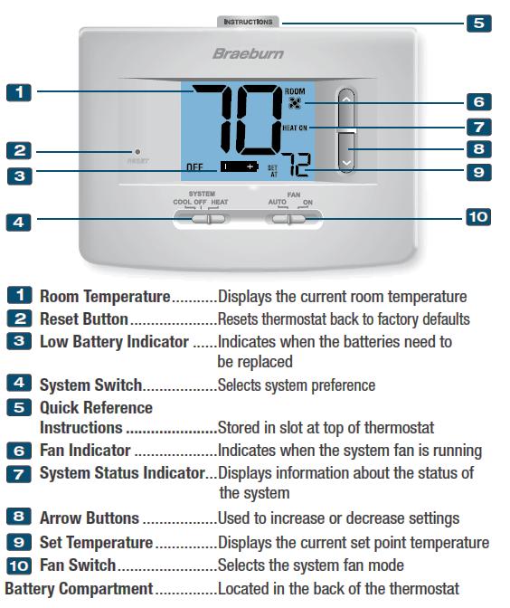
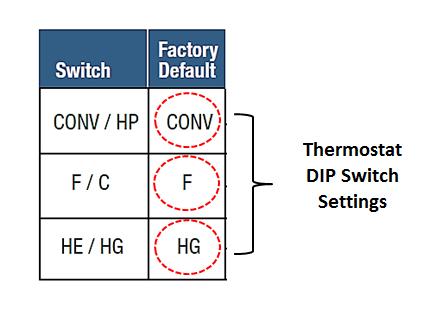
11 Thermostat, RF Thermostat - Description Thermostat IFS Part # This document pertains to systems that have serial numbers that begin with 36 or 37. Component Location Bunk, above Bed, Side wall or closet Description and Application The Idle Free Thermostat contains a LCD display and two Slide Switches. The IFS Thermostat uses two AA Batteries to power the display and to send switch signals to the Idle Free Relay Group (RF106). The left slide switch is used to turn on the air conditioner or turn on the heat. The center position of the left slide switch turns the system OFF. The right slide switch has two positions marked AUTO & ON. The AUTO position is used if the system user wishes to have the air conditioner s evaporator fan turn on and off with the air conditioning compressor circuit. Leaving this switch in the ON position will continuously run the evaporator fan regardless of the compressor s current mode. The driver should place the Fan Switch in the ON position for best system performance. Placing the Thermostat Fan switch in the ON position will eliminate 10% of the Inverter start up power needs. The IFS Thermostat has two soft push buttons located under the LCD Display. The center soft button is used to display the current room temperature and turn on the display s backlight. The right soft switch increases the temperature setting of the thermostat and the left soft button decreases the temperature of the room setting. A low Voltage Battery Indicator Icon is shown on the display when the AA batteries need to be changed. HEAT MODE The thermostat is used to turn on the Idle Free water heater and the Heat relay (Relay Group RF106). The thermostat when in HEAT Mode provides 12VDC power to the Truck s Bunk Blower fan, The Thermostat s temperature settings are not used in Heat Mode, The truck s bunk controls are used to provide Bunk Heat temperature control. Technical Information The Idle Free Thermostat can be separated from its mounting base. The mounting base contains terminals for the wiring harness the runs between the thermostat and the UBB (REF Sheet #63110). The Thermostat is used to operate the Relay Group located in the UBB (RF106). The Thermostat is supplied with 12VDC Power from the 2AMP fuse located on the front of the UBB (RF108). The 12 VDC power enters the thermostat base on the red wire, R terminal (Jumped) to a second R marked terminal. The thermostat switch positions determine where, how and when 12VDC power is sent to the UBB Relay Group. G Terminal - Green wire; 12VDC to the Evaporator Relay Y Terminal - Yellow Wire; 12 VDC to the Compressor Relay B terminal Blue Wire; 12VDC to the Heat Relay The back side of the Thermostat includes 3 DIP switches that need to be in the proper position for the Thermostat to Function Properly 1. CONV/HP = HP 2. F/C = F 3. HE/HG = HG Common Failure Issues User fails to understand that the left Mode switch in A/C mode has a 5 minute delay between ON then OFF then ON. This causes confusion and is dealt with by instructing the driver to place right switch in the auto position to see if the Thermostat is in the 5 minute delay window. If the evaporator fan is not running when the Mode switch is in COOL mode, the thermostat is in the 5 minute delay mode. Drivers need to operate the Thermostat with the Fan Switch in the ON position. The ON position eliminates the need to start the Evaporator Blower fan and the compressor at the same time.
12 Thermostat, RF Thermostat - Description

13 Power Converter RF Shore Power Description Power Converter, 120VAC to 12VDC Shore Power IFS Part # Component Location UBB, Under Bed Module, Upper level This document pertains to systems that have serial numbers that begin with 36 or 37. Description and Application The Idle Free Power Converter converts incoming 120VAC power (Shore Power) to 12VDC power. When Shore Power is available, the converter maintains the Idle Free AGM battery voltage. The Power Converter has a rated amperage output of 55 AMPS DC. The Idle Free air conditioner uses less than 50 AMPs DC and when using the Power Converter (Shore Power), the AGM battery voltage level maintains 12.6 VDC or higher. Whenever the Power Converter s DC voltage rises past 13.2VDC, the Idle Free Battery separator closes and connects the Idle Free battery bank to the truck s battery bank (Battery Separator RF101). If the combined voltage of both battery banks remains above 12.8VDC, both battery banks will remain connected and both Battery banks will receive a charge from the Idle Free Power Converter. The Power Converter s 120VAC circuit begins on the truck s exterior with a covered receptacle (male) that is used to receive the female end of an extension cord. The Power Converter s DC circuit begins at the bulkhead DC Connection posts on the lower back corner of the UBB (UBB RF108) Potential Issues 1. Installer connects a ground power supply cable to the wrong (+ or -) battery post. This action causes the Power converter s DC fuses to fail. The (2, 30 AMP) fuses are located on the rear side of the Power Converter. 2. Shore Power (plugging in) is perceived to be a direct use of 120VAC power that directly powers the 120VAC Idle Free air conditioning circuit. Shore Power is only used to convert AC to DC. The inverter is always the 120VAC power provider for the Idle Free air conditioner.
14 Power Converter RF Shore Power Description

15 Inverter, 12VDC to 120VAC IFS Part # Watt, Sine Wave Component Location UBB, Under Bed Module, Lower level Inverter RF This document pertains to systems that have serial numbers that begin with 36 or 37. Description The Idle Free Inverter provides 120VAC sine wave power for the Air Conditioner s Compressor and Evaporator Blower Fan. The Inverter is rated at 1500 watts continuous with a 3000 watt Surge Capacity. The Inverter has a GFCI outlet that is used to protect against electrical shock hazards. The Inverter is located in the UBB Module (RF110), lower level. The Inverter is installed with Stand-By mode activated. Stand-by mode is used as an automatic ON/OFF feature (shuts off automatically, ON with load > 20 watts. A 120VAC Power Strip is included with the Idle Free system. The power strip can be used to power driver needs. Some small wattage 120VAC convenience devices can be powered with the inverter (if managed properly). Application 120VAC Inverter Power is sent from the Inverter through two relays to activate the 120VAC Compressor circuit and the 120VAC Evaporator circuit. Both Relays are controlled with a 12VDC signal from the Idle Free Thermostat (RF103). The Compressor Relay sends it 120VAC to the exterior located APU. The Exterior APU Module s Compressor 120VAC Circuit contains a pressure switch, condenser fan relay, run capacitor, start capacitor, and a compressor. The Evaporator Relay sends its power to the Evaporator module to power the single speed 120VAC Blower fan typically located in a bunk closet. Component History, Issues 1. GFCI will trip occasionally when Idle Free system is turned off suddenly by starting the truck. The user manual instructs the driver to turn OFF the air conditioner with the Thermostat Only. 2. The Inverter may over load (Red Light condition) if the Start Capacitor is not properly connected to the run capacitor. The connection quality is a factor especially after a year of operation. Service is required for the electrical APU Harness, Clean, Tight, & Corrosion application for all APU electrical connections. 3. Inverter may shut down if 1500 watts is exceeded or 3000 watts surge is exceeded. The Inverters maximum output is exceeded when the air conditioner is turned off for a few seconds and then back ON by turning the Ignition key ON and then OFF. This action forces the air conditioner to attempt to start however the pressure present on the high side Freon circuit may be too high for the inverter (output) to overcome. The correct USER procedure is to turn the air conditioner off using the slide switch on the face of the thermostat. 4. The inverter may overload if a microwave is used that exceeds the maximum output rating of the inverter. This tends to be the case on any microwave rated at >700watts. The microwave rating is based on run watts not the watts needed to start the microwave. Idle Free cannot control what is plugged into the inverter and the user needs to understand the inverter parameters. 5. Drivers need to understand the Do s and Don ts when using the Idle Free air conditioner. The inverter will display LED lights that will show the reason for the inverter shut down. Learning to properly react to these indicators will eliminate most inverter issues. 6. A permanent label/sticker is affixed to the underside of the UBB Cover. This information label contains helpful information for troubleshooting the inverter.


16 Inverter RF The STATUS light is the bottom light on the face of the inverter, to the right of the GFCI, 120vac outlet.


17 Inverter RF Top Light: DC i l li h

18 Inverter RF Center Light: Center Light: I l d l l Inverter load level This center light will not be lit when the inverter is in stand-by mode or if the inverter is turned off or if the Power Saving Mode Normal Plugged into shore Power or Reefer Running (OKAY) Out of Battery Power Overheated (ventilation) Inverter was over loaded Bottom Light: Status Light This light is the key to what is happening to the inverter and knowing its status will help determine

19 Inverter RF GFCI Reset Procedures 1. Locate the GFCI Outlet, found on the end of the inverter. 2. Turn the inverter OFF using the black switch, located to the left of the white 120VAC outlet. 3. Turn the Inverter ON using the black switch, located to the left of the white 120VAC outlet. 4. Push the Reset Button in within 5 seconds of turning the inverter switch to the ON position. OR 1. Locate the GFCI Outlet found on the end of the Inverter. 2. Push and Hold the Reset Button IN. 3. Turn the Inverter Switch to the OFF position. 4. Turn the Inverter Switch to the ON position. Power Switch 5. Holds reset button IN until you feel it Click. Reset Button GFCI Indicator Light Note; on some Inverter models the GFCI indicator light is located in this location.
20 Inverter RF Inverter Diagnostics The Idle Free Inverter has all the indicators in place to determine why it is or is not working. The Top indicator light is the Input DC voltage The Bottom indicator light is green or flashing green when the inverter is ON or in stand-by mode The Center Indicator light is only lit when an inverter load is present, Green = Okay, Red = too High The GFCI has its own indicator light that replicates the bottom light (Status) Green or Flashing Green. If the bottom light is RED the GFCI indicator light will not be lit because the inverter is shut down when the status light is RED. The inverter is fused internally with non-replaceable fuses. The inverter fuse power from the AGM battery bank is located in the APU, exterior frame mounted unit, above the battery separator. The inverter can be used as a diagnostic tool. The top light for battery voltage level input The Center light as a load light green = Okay, Red + too High Bottom Light why the inverter shut down (Red Light = Over load), (Flashing Red = Battery voltage too low) Bottom Light gives current state of the inverter, Green = OKAY, Flashing Green = Stand-By
21 Relay Group, (36) RF Power Relays, explanation Relay Group Component Location: Truck Interior Bunk Area UBB, upper level UBB (REF Sheet, RF110) This document applies to systems with serials numbers that begin with 36 Description & Application The Relay Group is made up of 4 Ice Cube Relays. The Relays are mounted on a DIN Rail, in the upper portion of the UBB. The Relays are used to power the Thermostat, Evaporator Fan, Compressor Circuit, & Heat Circuit. The Relays use a 12VDC coil. The Heat Relay is a single pole, triple throw relay (SPTT) The Compressor Relay, the Evaporator Relay and the Ignition Relay are single pole; single throw relays (SPST) The Ignition Relay controls 12VDC (2 AMP fuse) power used to power the Thermostat. The Ignition Relay is wired to use the normally closed contacts within the relay. When the truck s ignition is turned on, 12VDC power is sent to the Ignition Relay and the normally closed contacts are opened. Opening the Ignition Relay circuit (truck ignition ON) disables the Thermostat functions (Heat and Air conditioning) (RF103). The Evaporator Relay controls 120VAC power that is used to run the evaporator blower fan. The Evaporator Relay is wired to use the normally open contacts within the relay. When the thermostat is set to turn on the evaporator fan, the 12 VDC coil is activated and the 120VAC is sent through the relay to the evaporator fan. The Compressor relay controls 120VAC power that is used to run the compressor circuit. The Compressor Relay is wired to use the normally open contacts within the relay. When the thermostat is set to turn on the compressor circuit, the 12 VDC coil is activated and the 120VAC is sent through the relay to the APU (exterior), compressor circuit (RF112). The Heat relay controls 12DC power that is used to run the Truck s Blower Fan circuit. The Truck s Blower fan circuit is switched to Idle Free battery power whenever the Heat relay is activated. The Heat relay is activated by moving the thermostat mode switch to HEAT. The Heat relay is wired to use the normally closed contacts and the normally open contacts, within the relay. When the thermostat is set to the HEAT mode, the 12 VDC coil is activated and 12VDC fused power from the Idle Free battery bank is sent through the relay, to the Truck Fan motor and fan control circuits (1-3). When the relay is not activated (Heat switch is OFF or ignition switch is ON), the normally closed circuit passes through the truck s blower fan power needs with 12 VDC Truck Battery Power. The 3 circuits in this relay are not all used for every truck. Instructions are included in the installation manual regarding the circuits needed for each truck brand installation application. Overview The Relay Group is controlled by the Thermostat. The Thermostat (RF103) sends 12VDC signals to the individual relays in the Relay Group. The Relay Group contains Ice Cube Relays. Ice Cube (type) Relays enable the use of both ac and dc voltages through the relay contacts. Common Issues The Relay Group has no history of issues. Service The Relay Group does not require any service

 This Row is Fused Idle Free Battery Power NO (Normally Open) NC")
22 Relay Group, (36) RF Power Relays, explanation This document applies to systems with serials numbers that begin with 36 Not Used Direction of Current Flow Top View of Relay Group 120VAC Inverter source 12VDC, Fused (Purple) NO Heat Relay NC Ground Ground Ground Ground Direction of Current Flow 12VDC Thermostat Heater signal BLUE 12VDC Thermostat Compressor signal from the timer YELLOW 12VDC Thermostat Evaporator signal GREEN 12VDC Ignition source signal GREY 12VDC Thermostat Power, (Red) This Row is Fused Idle Free Battery Power NO (Normally Open) NC Normally Closed Heat Relay This Row is Fused Truck Battery Power This Row (+ & -) is the coil activation row This Row feeds the 12VDC to the component being controlled.
23 Relay Group, (36) RF Power Relays, explanation Fan Relay Wiring Evaporator & Compressor, Relay Wiring
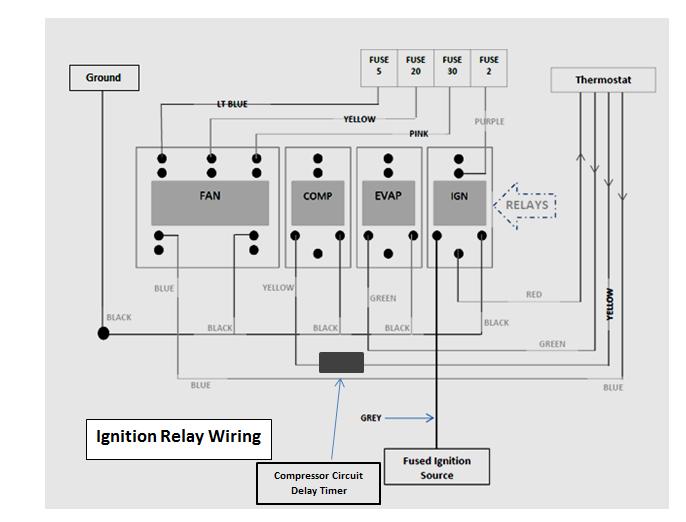
24 Relay Group, (36) RF Power Relays, explanation Ignition Relay Wiring Compressor Circuit Delay Timer Troubleshooting: Use the relay Black 18 gauge wires for ground service connections Ignition relay must be OFF (not activated) for any of the other relays to receive 12VDC power. The evaporator relay and the compressor relay pass through 120VAC when activated by the thermostat. The inverter must be turned on with a green or flashing green light located on the GFCI outlet. (RF105). To check each relay for coil activation place your volt meter on DC and place probes into the relay coil terminals (page 13). Use the ground for the relay being checked, The relay 12VDC+ wires are from the thermostat or the ignition source, colors for 12VDC coil operation are: Grey = Ignition Relay Green = Evaporator Relay Yellow = Compressor Timer & Compressor Relay From Thermostat Blue = Heat Relay, (triple relay) Relay coils are activated with 12 VDC from thermostat switches Thermostat switch position determine 12VDC to relays Ignition relay passes through fused 12VDC power when truck ignition is turned OFF Evaporator relay passes through 120VAC when thermostat is in COOL mode or Fan switch is in ON mode Compressor Relay passes through 120VAC when thermostat is in COOL mode and temperature setting is calling for COOL. Compressor Relay is delayed 8 seconds using a Timer relay. Heat Relay passes through 12VDC when thermostat is in heat mode. Not all heat circuits are used for all trucks. Fuse panel fuses all 3 heat circuits (RF108).

25 Relay Group, (36) RF Power Relays, explanation Timer for the compressor circuit The Compressor Circuit includes a timer that delays the start of the compressor Circuit 8 seconds. The compressor circuit will start 8 seconds after the thermostat calls for COOL. During the 8 second delay the evaporator fan will come on and be up to full speed. The compressor delay circuit is used to eliminate the added surge power needed to start the evaporator blower fan. The Thermostat sends its 12 VDC signal to the Time Delay relay prior to the Compressor relay. Under Bed Box (UBB)
26 Relay Group, (36) RF Power Relays, explanation
27 Relay Group, (3.7) RF Power Relays, explanation This document pertains to systems that have serial numbers that begin with 37. Relay Group Component Location: Truck Interior Bunk Area UBB, upper level UBB (REF Sheet, RF110) Description & Application The Relay Group is made up of 4 Ice Cube Relays. The Relays are mounted on a DIN Rail, in the upper portion of the UBB. The Relays are used to power the Thermostat, Evaporator Fan, Compressor Circuit, & Heat Circuit. The Relays use a 12VDC coil. The Heat Relay is a single pole, triple throw relay (SPTT) The Compressor Relay, the Evaporator Relay and the Ignition Relay are single pole; single throw relays (SPST) The Ignition Relay controls 12VDC (2 AMP fuse) power used to power the Thermostat. The Ignition Relay is wired to use the normally closed contacts within the relay. When the truck s ignition is turned on, 12VDC power is sent to the Ignition Relay and the normally closed contacts are opened. Opening the Ignition Relay circuit (truck ignition ON) disables the Thermostat functions (Heat and Air conditioning) (RF103). The Evaporator Relay controls 120VAC power that is used to run the evaporator blower fan. The Evaporator Relay is wired to use the normally open contacts within the relay. When the thermostat is set to turn on the evaporator fan, the 12 VDC coil is activated and the 120VAC is sent through the relay to the evaporator fan. The Compressor relay controls 120VAC power that is used to run the compressor circuit. The compressor relay receives its ground from the low pressure switch located in the exterior, condensing unit. If the condensing unit loses its refrigerant, the ground goes away and opens the compressor circuit. The Compressor Relay is wired to use the normally open contacts within the relay. When the thermostat is set to turn on the compressor circuit, the 12 VDC coil is activated and the 120VAC is sent through the relay to the APU (exterior), compressor circuit (RF112). The Heat relay controls 12DC power that is used to run the Truck s Blower Fan circuit. The Truck s Blower fan circuit is switched to Idle Free battery power whenever the Heat relay is activated. The Heat relay is activated by moving the thermostat mode switch to HEAT. The Heat relay is wired to use the normally closed contacts and the normally open contacts, within the relay. When the thermostat is set to the HEAT mode, the 12 VDC coil is activated and 12VDC fused power from the Idle Free battery bank is sent through the relay, to the Truck Fan motor and fan control circuits (1-3). When the relay is not activated (Heat switch is OFF or ignition switch is ON), the normally closed circuit passes through the truck s blower fan power needs with 12 VDC Truck Battery Power. The 3 circuits in this relay are not all used for every truck. Instructions are included in the installation manual regarding the circuits needed for each truck brand installation application. Overview The Relay Group is controlled by the Thermostat. The Thermostat (RF103) sends 12VDC signals to the individual relays in the Relay Group. The Relay Group contains Ice Cube Relays. Ice Cube (type) Relays enable the use of both ac and dc voltages through the relay contacts. Common Issues The Relay Group has no history of issues. Service The Relay Group does not require any service
28 Relay Group, (3.7) RF Power Relays, explanation Not Used Direction of Current Flow Top View of Relay Group 120VAC Inverter source 12VDC, Fused (Purple) NO Heat Relay NC Direction of Current Flow 12VDC Thermostat Heater signal BLUE Ground 12VDC Thermostat Compressor signal from the timer YELLOW Orange wire from 4 pin connector 12VDC Thermostat Evaporator signal GREEN Ground 12VDC Ignition source signal GREY Ground 12VDC Thermostat Power, (Red) This Row is Fused Idle Free Battery Power NO (Normally Open) NC Normally Closed Heat Relay This Row is Fused Truck Battery Power This Row (+ & -) is the coil activation row This Row feeds the 12VDC to the component being controlled.


29 Relay Group, (3.7) RF Power Relays, explanation Fan Relay Wiring Evaporator & Compressor, Relay Wiring

.")
30 Relay Group, (3.7) RF Power Relays, explanation Ignition Relay Wiring Compressor Circuit Delay Timer Troubleshooting: Use the relay Black 18 gauge wires for ground service connections Ignition relay must be OFF (not activated) for any of the other relays to receive 12VDC power. The evaporator relay and the compressor relay pass through 120VAC when activated by the thermostat. The inverter must be turned on with a green or flashing green light located on the GFCI outlet. (RF105). To check each relay for coil activation place your volt meter on DC and place probes into the relay coil terminals (page 13). Use the ground for the relay being checked, The relay 12VDC+ wires are from the thermostat or the ignition source, colors for 12VDC coil operation are: Grey = Ignition Relay Green = Evaporator Relay Yellow = Compressor Timer & Compressor Relay From Thermostat Blue = Heat Relay, (triple relay) Relay coils are activated with 12 VDC from thermostat switches Thermostat switch position determine 12VDC to relays Ignition relay passes through fused 12VDC power when truck ignition is turned OFF Evaporator relay passes through 120VAC when thermostat is in COOL mode or Fan switch is in ON mode Compressor Relay passes through 120VAC when thermostat is in COOL mode and temperature setting is calling for COOL. Compressor Relay is delayed 8 seconds using a Timer relay. Heat Relay passes through 12VDC when thermostat is in heat mode. Not all heat circuits are used for all trucks. Fuse panel fuses all 3 heat circuits (RF108).
31 Relay Group, (3.7) RF Power Relays, explanation Timer for the compressor circuit The Compressor Circuit includes a timer that delays the start of the compressor Circuit 8 seconds. The compressor circuit will start 8 seconds after the thermostat calls for COOL. During the 8 second delay the evaporator fan will come on and be up to full speed. The compressor delay circuit is used to eliminate the added surge power needed to start the evaporator blower fan. The Thermostat sends its 12 VDC signal to the Time Delay relay prior to the Compressor relay. Under Bed Box (UBB)
32 Relay Group, (3.7) RF Power Relays, explanation ORANGE This wire is orange on 3.7 systems and originates on the exterior located, low pressure switch, this is a ground wire.
 Starts at a truck specific ignition source and powers the UBB ignition relay Description & Application The DC Ignition")


33 Ignition Cut-Out Circuit RF Ignition Cut-out circuit, explained Ignition Cut-Out Circuit This document pertains to systems that have serial numbers that begin with 36 or 37. Component Location Bunk Area Connected to the back side of the UBB (RF110) Starts at a truck specific ignition source and powers the UBB ignition relay Description & Application The DC Ignition Cut-out circuit is used to disable the Idle Free system when the truck s engine is running. The Ignition Cut-out circuit sends fused 12VDC power from the ignition source to the UBB. The Ignition Cut-out circuit cuts the 12VDC power to the Thermostat when the truck s engine is running. 1 st Relay is Ignition Issues 1. The Ignition Cut-out circuit has been installed incorrectly on rare occasions. When the installation instructions are not followed, the ignition cut-out circuit is connected to the accessory circuit instead of an ignition only circuit. This causes the Idle Free air conditioner or heater to shut off whenever the truck s ignition key is moved to the accessory position. When the user wants to listen to the radio, the Idle Free system shuts down. 2. The Idle Free system user turns the ignition key to the ON position without turning the air conditioner to the OFF position (thermostat). When the user turns the ignition key back to OFF, the Idle Free air conditioner is forced to start without a 5 minute delay (Delay is built into the Thermostat). The Idle Free air conditioner start attempt (forced) under these conditions may overload the inverter (RF105). Ignition harness plugs into the back of the UBB Service The Ignition circuit does not require service. The Ignition cut-out fuse location varies by truck application. The Ignition cut-out fuse is located within 12 inches of the ignition connection point. Freightliner and International trucks begin the ignition cut out circuit at the ignition key. The Mack Ignition cut out circuit begins at the dash panel (passenger side, top). The Kenworth Ignition circuit begins in the fuse panel, on the floor behind the brake pedal. Do not use the truck s ignition to turn off the air conditioner. Always use the Thermostat Mode Switch to control Air conditioning and Heat functions.
34 Ignition Cut-Out Circuit RF Ignition Cut-out circuit, explained
 Description & Application The DC Fuse Holder contains 4 openings for fuses.")
 powers the bunk Blower fan when the Idle Free water heater is a part of the system. This fuse is a 30 AMP fuse.")
 The 3 rd & 4 th fuses (from the top) are only used in some (truck specific) applications where bunk heater control is a part of more than one circuit.")
35 DC Fuse Holder RF DC Fuse Holder - UBB DC Fuse Holder IFS Part # This document pertains to systems that have serial numbers that begin with 36 or 37. Component Location Truck Interior Bunk Area Connected to the inside, top level of the UBB (RF110) Description & Application The DC Fuse Holder contains 4 openings for fuses. The top fuse is always a 2 AMP fuse that powers the Volt Meter (RF102) and the Thermostat (RF103). The 2 nd fuse (from the top) powers the bunk Blower fan when the Idle Free water heater is a part of the system. This fuse is a 30 AMP fuse. (For Mack and KW trucks the remaining fuse positions are not used.) The 3 rd & 4 th fuses (from the top) are only used in some (truck specific) applications where bunk heater control is a part of more than one circuit. International, Freightliner, & Volvo require fuses place in positions 3 & 4. When an Idle Free Heater is a part of the system, truck specific instructions are included along with the OEM fan harness Kit (IFS Part# 91801). Kit includes the fan harness, installation instructions and fuse placement instructions. Heat Relay (see RF 106) Overview The DC Fuse Holder may contain up to 4 fuses. The top fuse is used in all applications (see above paragraph). Fuse #2 is used in all heater applications and contains a 30 AMP fuse used to provide power for the Bunk Blower fan. This fuse supplies fan power whenever the Idle Free Heater is activated by turning the Thermostat Mode switch to Heat (RF103). Fuses 2, 3, & 4 (positions from top) are connected to the bottom row of the Heat Relay. Fuse 2 uses a 12 Gauge wire. Fuse 3 uses a 14 gauge wire. Fuse 4 uses an 18 gauge wire. History The DC Fuse Holder can be fused incorrectly during installation. Fuse placement instructions are included with every heater harness installation Kit. Fuse 2 30AMP 12 Gauge, Pink Fuse 3 20AMP 14 Gauge, Yellow Fuse 4 10AMP 18 Gauge, Lt Blue
36 DC Fuse Holder RF DC Fuse Holder - UBB
37 ReeferLink Connection RF109 ReeferLink, Explanation ReeferLink Connection IFS Part # This document pertains to systems that have serial numbers that begin with 36 or 37. Component Location APU & Reefer Unit Description & Application The Idle Free ReeferLink Technology is patented and should not be used to power other battery based APUs. The Reefer Unit must have an alternator rating of 65 AMPS or greater. The Idle Free ReeferLink connection Kit should be used to supplement the Idle Free APU system. The ReeferLink Connection Kit consists of 4 parts: 1. APU DC Connection cables, internal and panel mount receptacles (fused). 2. Truck connection connector, body & cover. 3. Trailer connection connector, body & cover (fused). 4. Truck to Trailer interconnects Cable set. The ReeferLink Connection provides the 12VDC power available when the Refer unit is running to be used to maintain the Idle Free APU battery bank voltage and the trucks 12VDC Battery voltage levels. Refrigerated Trailers have systems in place that start their reefer units when contents of the trailer require temperature management. Refrigerated Trailers have systems in place that start their reefer units when their starter battery requires charging. Typical refer units will start their engines when the starter battery requires charging. A starter battery voltage of <12.1VDC will engage the start circuit of the reefer unit. If the Idle Free ReeferLink connection is in place the reefer unit will engage its start circuit whenever the reefer s battery and the Idle Free battery bank drop to <12.1VDC. The reefer unit will continue to operate until the alternator output amperage drops to <8 AMPS. When the reefer unit is running, with the Idle Free ReeferLink connection in place, the following will take place: 1. Reefer Battery and Idle Free Battery bank will see alternator output voltage and amperage. 2. Reefer Output Amperage will be based on: a. APU Mode (air conditioning or Heat) b. Battery voltage level of Idle Free battery bank, Reefer starter battery, truck starter battery bank. 3. Reefer Alternator will close the Idle Free battery separator when the Idle Free battery bank rises to 13.2VDC. The truck and trailer can be connected (ReeferLink Connection), when the truck is moving, in the event that: a. Truck s alternator fails b. Reefer s alternator fails The trucks alternator can be used to keep the reefer units 12VDC systems operating by using the ReeferLink Connection. The reefer unit s alternator can be used to keep the truck s 12VDC systems operating by using the ReeferLink Connection. The Reefer Unit must have an alternator rating of 65 AMPS or greater. The reefer connection kit (reefer portion) includes a 250 AMP in line fuse. The reefer connection kit (reefer portion) DC connections must be made in this way; connect the negative cable to the reefer battery negative post & connect the positive reefer connect positive battery cable to the positive output post on the alternator. The alternator must be rated at 65 AMPS or greater. The positive connection must be made at the reefer alternator positive output post. Overview The Idle Free Reefer Link system is a controlled DC connection between the truck and the reefer unit. The ReeferLink connection provides battery charging for the Idle Free APU. The controlled DC connection between the truck and the trailer allows the truck or the reefer unit to supply power to each other. In the event that a truck alternator or a reefer alternator fail, the ReeferLink connection is used to literally connect the 12VDC connections (truck and reefer trailer) together.
38 ReeferLink Connection RF109 ReeferLink, Explanation Overview (continued) The Idle Free Reefer Link system will allow the reefer unit to start from the Idle Free APU batteries directly by connecting the reefer trailer to the truck using the ReeferLink interconnect Cable set. Using the ReeferLink Connection to power the APU has the benefit of using nontaxed fuel for non-road use. ReeferLink Connection Kit consists of 4 parts: 1. APU DC Connection cables, internal and panel mount receptacles (fused). The APU has internal cables added along with DC panel mount receptacles. The added panel mount receptacles added to the side of the APU provide a quick connect point for the truck side of the ReeferLink Connection Kit. The APU DC Connections are fused with a 250 AMP fuse to protect the truck and trailer. 2. Truck connection connector, body & cover. The truck connection portion is mounted near the connection point on the back of the bunk where the air hoses and electrical cord is housed for the standard truck to trailer connections. 3. Trailer connection connector, body & cover (fused). The trailer connection kit includes a 250 AMP fuse used to protect the truck and reefer unit from short circuits. The trailer portion of the ReeferLink Connection uses a permanent mount for the Anderson connector. This mount is typically mounted near the electrical plug-in and the air-line connection point. 4. Truck to Trailer Interconnect Cable set. The Truck to Trailer Interconnect Cable Set is typically kept in the driver s side box. This connection can be made anytime however it is best practice to only mate the truck and trailer together when the need arises or when the truck is stationary. Service The ReeferLink Connections require regular service. This service includes: 1. Checking for tight connections 2. Checking for Clean Connections 3. Adding battery terminal protection spray to exposed DC connection points. Troubleshooting The ReeferLink Connections can be checked using a DC Voltmeter. 1. Check the Reefer side connector for DC Voltage by placing the Voltmeter probes onto the lugs located inside the connector body. The connector body has + or indicator markings on the connector body near the terminal connection points. 2. If DC voltage is not present, check the 250 AMP fuse, alternator connection, and the Reefer s Battery connections. 3. The truck side ReeferLink Connector should always show APU DC battery voltage. Check the connector located on the back side of the bunk for 12VDC power. If 12VDC power is not present, check the APU panelmount connectors (exterior of APU). Remove the panel mount connectors (Counter clockwise to remove, clockwise to tighten) 4. You should always have 12VDC at the APU panel-mount connectors. If no DC is present, remove the back cover from the APU and check for loose or missing cables. History of Issues The ReeferLink issues include: 1. Cables between the truck and trailer un-secured during driving periods resulting in lost or broken cables. 2. Wrong DC + connection point (battery + instead of alternator +) resulting in the reefer s control display showing a fault code.
39 UBB, (36 only) RF110 Under Bed Box, Explained UBB, Under Bed Box or Under Bed Module Component Location Truck Interior Bunk Area Under Bed, Floor mounted This document pertains to systems that have serial numbers that begin with 36. Description & Application The UBB (Under Bed Box) is the connection module for the Idle Free System The UBB contains the following components: 1. Inverter (RF105) 2. AC to DC Power supply (Shore Power)(RF104) 3. Relay Group (RF106) 4. DC Fuse Holder (RF108) 5. Timer Relay, Compressor Circuit (RF106) The back side of the UBB Box contains connection Hubs for the following Components: 1. DC Cables (From APU)(RF113) 2. Ignition Harness (RF107) 3. Volt Meter (RF102) 4. Thermostat (RF103) 5. Evaporator Fan (RF111) 6. Shore Power, Harness Connection point from Power inlet plug. 7. Compressor Circuit, includes water heater signal wire (Blue) VAC (10 AMP) connection socket 9. OEM HVAC (Fan harness connections for Truck bunk blower fan)(rf106) Overview All components contained in the UBB and all components that plug into the UBB have their own reference sheets (RF). The underside of the UBB Cover includes a troubleshooting guide. The UBB is used for diagnostic entry into the Idle Free system. The Relay Group is tested to see if DC voltage from the Thermostat is reaching the relays. The inverter GFCI reset is located on the end of the inverter, located in the lower level of the UBB (RF105). Common Issues The UBB has a history involving GFCI tripping of the inverter or red light conditions on the inverter. These issues go away after the driver better understands how to properly use the system (RF105). Service The UBB does not require any service however connection quality needs to be maintained and proper ventilation needs to be present around the UBB to allow for air flow to the inverter and the AC to DC Power Converter
40 UBB, (36 only) RF110 Under Bed Box, Explained 1/3 rd of the label under the UBB Cover 2/3 rd of the label under the UBB Cover
41 UBB, (36 only) RF110 Under Bed Box, Explained 10 AMP, 120 VAC power outlet Shore Power Plug = Ground center, neutral and hot 120VAC outside terminals Evaporator = Ground center, neutral and hot 120VAC outside terminals, on when thermostat is in cool mode or thermostat fan switch turned ON. OEM Fan Harness: Top Terminals, 12 GA, 30 AMP Middle Terminals, 14 GA, 20 AMP Bottom Terminals, 18 GA, 10 AMP Thermostat, 4 WIRE, RED = 12VDC, to Thermostat GREEN = Evaporator Relay, 12VDC, from Thermostat YELLOW = Compressor Relay, 12VDC, from Thermostat to Timer Delay Relay Blue = Heater Relay, 12VDC, from Thermostat UBB to APU = Ground 2 from right,, neutral and hot 120VAC outside of ground terminal, far terminal is heater on signal, Blue 18 gauge wire. 120 VAC on when thermostat calls for COOL. Volt Meter, on when 2 AMP fuse is in holder Ignition, single grey wire from truck ignition source, fused input from source 250 AMP Fused power from AGM batteries trough RED DC connector on rear side of APU (IFS#32043) Ground Cable from AGM battery Power, through Black DC Connector on rear side of APU (IFS#32045)
42 UBB, (36 only) RF110 Under Bed Box, Explained
43 UBB, (37 only) RF110 Under Bed Box, Explained UBB, Under Bed Box or Under Bed Module This document pertains to systems that have serial numbers that begin with 37. Component Location Truck Interior Bunk Area Under Bed, Floor mounted Description & Application The UBB (Under Bed Box) is the connection module for the Idle Free System The UBB contains the following components: 1. Inverter (RF105) 2. AC to DC Power supply (Shore Power)(RF104) 3. Relay Group (RF106) 4. DC Fuse Holder (RF108) 5. Timer Relay, Compressor Circuit (RF106) The back side of the UBB Box contains connection Hubs for the following Components: 1. DC Cables (From APU)(RF113) 2. Ignition Harness (RF107) 3. Volt Meter (RF102) 4. Thermostat (RF103) 5. Evaporator Fan (RF111) 6. Shore Power, Harness Connection point from Power inlet plug. 7. Compressor Circuit, includes water heater signal wire (Blue) VAC (10 AMP) connection socket 9. OEM HVAC (Fan harness connections for Truck bunk blower fan)(rf106) Overview All components contained in the UBB and all components that plug into the UBB have their own reference sheets (RF). The underside of the UBB Cover includes a troubleshooting guide. The UBB is used for diagnostic entry into the Idle Free system. The Relay Group is tested to see if DC voltage from the Thermostat is reaching the relays. The inverter GFCI reset is located on the end of the inverter, located in the lower level of the UBB (RF105). Common Issues The UBB has a history involving GFCI tripping of the inverter or red light conditions on the inverter. These issues go away after the driver better understands how to properly use the system (RF105). Service The UBB does not require any service however connection quality needs to be maintained and proper ventilation needs to be present around the UBB to allow for air flow to the inverter and the AC to DC Power Converter


44 UBB, (37 only) RF110 Under Bed Box, Explained 1/3 rd of the label under the UBB Cover 2/3 rd of the label under the UBB Cover

45 UBB, (37 only) RF110 Under Bed Box, Explained 10 AMP, 120 VAC power outlet Shore Power Plug = Ground center, neutral and hot 120VAC outside terminals Evaporator = Ground center, neutral and hot 120VAC outside terminals, on when thermostat is in cool mode or thermostat fan switch turned ON. OEM Fan Harness: Top Terminals, 12 GA, 30 AMP Middle Terminals, 14 GA, 20 AMP Bottom Terminals, 18 GA, 10 AMP Thermostat, 4 WIRE, RED = 12VDC, to Thermostat GREEN = Evaporator Relay, 12VDC, from Thermostat YELLOW = Compressor Relay, 12VDC, from Thermostat to Timer Delay Relay Blue = Heater Relay, 12VDC, from Thermostat UBB to APU = Ground for compressor relay, neutral and hot 120VAC outside of ground terminal, far terminal is heater on signal, Blue 18 gauge wire. 120 VAC on when thermostat calls for COOL. Volt Meter, on when 2 AMP fuse is in holder Ignition, single grey wire from truck ignition source, fused input from source 250 AMP Fused power from AGM batteries trough RED DC connector on rear side of APU (IFS#32043) Ground Cable from AGM battery Power, through Black DC Connector on rear side of APU (IFS#32045)
46 UBB, (37 only) RF110 Under Bed Box, Explained


47 Evaporator Module RF111 Evaporator Module This document pertains to systems that have Evaporator Module serial numbers that begin with 36 or 37. IFS #91301 Component Location Truck Interior Bunk Area Located in the closet, on the closet, on a bunk side wall Description & Application The Evaporator Module contains an evaporator coil, an electric blower fan, and an expansion valve. The Evaporator s blower fan is a single speed, 120VAC fan, controlled by the Thermostat switch settings (RF103) and the Relay Group (RF106). The Evaporator coil and expansion valve control 134A refrigerant. The Evaporator Module has 2 refrigerant hoses, a drain hose and a power cord exiting out the bottom of the module. The refrigerant and drain hoses leave the bunk area through a 2 hole drilled into the base of the closet. The Evaporator Module includes an aluminum filter (rear location). The Evaporator Module weighs 25#s. Overview The Idle Free Evaporator Module is installed into the leaving area of the bunk. Service The Idle Free Evaporator has a removable aluminum filter that must be cleaned (water) in order to maximize performance. History of Issues The Evaporator must be maintained in a way that allows air to reach the rear side, filter. Keep driver s personal belongings away from the Evaporators air intake (coil & filter) During installation ensure that the screws used to secure the evaporator are not driven through the refrigerant core or the blower motor. Suggestion; have user place the right Thermostat switch (RF103) into the ON position, not the AUTO position. Leaving the Thermostat in the ON position when in Air Conditioning Mode will keep the room in a consistent temperature range. Trouble Shooting The Evaporator Fan receives its 120VAC power from the Inverter. The inverter must have a Green status light or a flashing green status light to enable the evaporator fan. The Thermostat must have its fan switch in the ON position to activate this fan motor OR the Thermostat must be in the COOL mode with a temperature set to below the current bunk temperature. The Thermostat sends 12VDC to the Evaporator relay. The evaporator relay (UBB, ice cube relay) passes through 120VAC when the relay coil receives 12VDC power (green wire) from the thermostat. The connection point for the Evaporator is the UBB back side, 3 pin connector, 2 nd from the top, marked EVAPORATOR. The outside pins are used to test for 120VAC power, red and white wires.
48 Evaporator Module RF111 Evaporator Module
 RF112 Compressor 120VAC Circuit Explanation Compressor Circuit Component Location Truck Exterior APU Frame Mount Top Level, Harness This document pertains to systems that have serial numbers")
49 Compressor Circuit, APU, (3.6 Only) RF112 Compressor 120VAC Circuit Explanation Compressor Circuit Component Location Truck Exterior APU Frame Mount Top Level, Harness This document pertains to systems that have serial numbers that begin with 36. Description & Application The Compressor Circuit connects the following components together: 1. Compressor 2. Heat Overload switch (Compressor Top) 3. Run Capacitor 4. Start Capacitor 5. Pressure switch (drier top) 6. In-line neutral connection All components listed above use 120VAC. Overview 1. The 120VAC Circuit begins in the APU with 2 Black wires connected to the pressure switch located on top of the Drier top. These connectors require a tight fit. 2. The next connection in the Compressor Circuit connects 2 in-line connectors together, blue wire into a white wire, using a male and female connectors, push together type. These connectors require a tight fit. 3. The next connection point is the Run Capacitor. The run capacitor has 5 connections divided into 2 connection points. (See figure #2). These connectors require a tight Figure 1 fit. 4. The next component is the Start Capacitor. The start capacitor is connected to the Run Capacitor using the 2 black wires, see Figure #2. Run Capacitor Top 5. The next connection is the Compressor Top connections. 4 connectors are located under the plastic cover. The Heat overload switch receives the Black wire from the drier top. The short wire that leaves the overload switch connects to the C terminal on the compressor Top. The Red wire from the Run Capacitor connects to the Top of the Compressor onto the S terminal. The remaining Compressor top terminal is the R terminal and this terminal receives the Blue wire from the Run Capacitor. These connections require a tight fit. Black Wire Blue Wire Blue Wire Common Issues, History Red Wire Black Wire Figure 2 The Compressor circuit has 2 areas to focus in on; Start Capacitor and Pressure switch (Drier top connections). These connections are the focal point when the compressor fails to start. Service The Compressor circuit needs to be maintained with tight connections. All components and connections need to be inspected for cleanliness, tightness, & corrosion treatment (prevention) (see next page).
50 120 Volt Connections, APU Service Procedures The Idle Free air conditioning 120 Volt Harness requires service to ensure proper system operation and performance. When the Idle Free APU connections are dirty or loose, the Idle Free inverter s GFCI may trip or the Inverter may overload & shutdown. An overloaded inverter (shown with a red status light, face of the inverter) may be caused by the start capacitor not engaging (needed to start the compressor) because the start capacitor connectors are dirty or loose. The Idle Free Inverter s GFCI outlet may trip due to dirty connections leaking voltage back to the inverter. Service APU, 120 Volt Air Conditioner Harness Connections Service Needs: Clean, tighten, and Protect all 120 volt APU connection terminals. Connection Terminals (13 total) Harness input, (White to Blue, Neutral) Harness Input Pressure Switch (drier), 2 connections (Black, Hot) Run Capacitor, 5 connections Compressor Top, 4 connections Tools needed Needle Nosed Pliers Side Cutters Parts needed Tie-straps, 8 inch, narrow 1 2 Procedure Overview 1. The Ties straps currently securing the 120 volt, APU air conditioning harness need to be removed to allow all connections to be serviced. 2. All connections need to be removed, cleaned and tightened so as to ensure a tight fit onto the appropriate connection point 3. All connections (cleaned & properly tightened) need to be treated with an appropriate preventative terminal protection spray. 3 4 IFS #63003 REV2
51 120 Volt Connections, APU Service Procedures Thermostat must be in the OFF position! Pressure Switch Connections (2, female push-on, black wire) 1. Remove pressure switch (drier) connectors 2. Clean pressure switch terminals 3. Tighten crimped female push-on terminals using a needle nosed pliers, tighten to near closed. 4. Return crimped and tightened terminals to the pressure switch terminals 5. Spray pressure switch connection points with the battery terminal protection spray. Pressure switch should look like this after the terminals are removed, cleaned, tightened, replaced and treated with battery terminal protection spray. IFS #63003 REV2
52 120 Volt Connections, APU Service Procedures Thermostat must be in the OFF position! Harness input, (White to Blue, Neutral) 1. Locate Neutral wire on IFS 120 volt air conditioning harness. The neutral wires are connected in line above the drier, white wire connected to a blue wire, male pushed into a female. 2. Clean both connectors (terminals) 3. Tighten female terminal using a needle nosed pliers, tighten to near closed. 4. Connect crimped and tightened terminals together 5. Spray pressure switch connection points with the battery terminal protection spray. IFS #63003 REV2
53 120 Volt Connections, APU Service Procedures Thermostat must be in the OFF position! Run Capacitor, 5 connections 1. Remove all 5 connectors from the run capacitor. 2. Clean all terminals 3. Tighten the 2 Blue wires, female terminals, using a needle nosed pliers, tighten to near closed. 4. Push both female, blue terminals back onto the (aluminum frame side) run capacitor, top and bottom posts. 5. Locate one of the black, 18 gauge wires from the start capacitor (mounted below the run capacitor). 6. Tighten the female connector end using the needle nosed pliers. (This step is critical and has been found to be a recurring problem, lose start capacitor connections!) 7. Push on the female start capacitor terminal to the open post on the same side along with the 2 blue wires. 8. Place a Tie Strap around these 3 connections and tighten. 9. Locate the removed red wire and the remaining black wire (start capacitor) 10. Tighten both terminal ends using the needle nosed pliers, red and black wires. 11. Install the tightened red and black capacitor wires onto the open side of the start capacitor. Place the Red wire onto the lower post and the black wire onto the upper post. The side post will not receive a terminal. 12. Place a Tie Strap around the red and black wire and tighten. 13. Spray the run capacitor connection points with the battery terminal protection spray. Tie strap in place on first set of run capacitor terminals, contains 2 blue wires and a back wire from the start capacitor. Run Capacitor with all terminals in place. 2 Ties straps are used; each set of terminals is tied separately. IFS #63003 REV2
54 120 Volt Connections, APU Service Procedures Compressor Top, 4 connections 1. Remove the screwed on cover from the compressor top. 2. Check the tightness and cleanliness of the connections. 3. If the 4 connectors are clean and tight, do not remove them from their connection point. 4. If any one of the connections is lose, remove it and use the needle nosed pliers to tighten the connector, place the tightened connector(s) back on to the appropriate terminal post. a. Black = C b. Red = S c. Blue = R 5. Spray all compressor terminals with battery corrosion spray. 6. Install cover, do not over tighten. If the cover is cracked, replace the cover. 7. Secure all lose wires with tie straps. 8. End of procedure IFS #63003 REV2

 may be caused by the start capacitor not engaging (needed to start the compressor) because the start capacitor connectors")
55 138 RF, 120 Volt Connections, APU Service Procedures, (3.6 only) This document pertains to systems that have serial numbers that begin with 36. The Idle Free air conditioning 120 Volt Harness requires service to ensure proper system operation and performance. When the Idle Free APU connections are dirty or loose, the Idle Free inverter s GFCI may trip or the Inverter may overload & shutdown. An overloaded inverter (shown with a red status light, face of the inverter) may be caused by the start capacitor not engaging (needed to start the compressor) because the start capacitor connectors are dirty or loose. The Idle Free Inverter s GFCI outlet may trip due to dirty connections leaking voltage back to the inverter. Service APU, 120 Volt Air Conditioner Harness Connections Service Needs: Clean, tighten, and Protect all 120 volt APU connection terminals. Connection Terminals (13 total) Harness input, (White to Blue, Neutral) Harness Input Pressure Switch (drier), 2 connections (Black, Hot) Run Capacitor, 5 connections Compressor Top, 4 connections Tools needed Needle Nosed Pliers Side Cutters Parts needed Tie-straps, 8 inch, narrow 1 2 Procedure Overview 1. The Ties straps currently securing the 120 volt, APU air conditioning harness need to be removed to allow all connections to be serviced. 2. All connections need to be removed, cleaned and tightened so as to ensure a tight fit onto the appropriate connection point 3. All connections (cleaned & properly tightened) need to be treated with an appropriate preventative terminal protection spray. 3 4 IFS #63003 REV2
 Thermostat must be in the OFF position!")
 connectors 2. Clean pressure switch terminals 3.")


56 138 RF, 120 Volt Connections, APU Service Procedures, (3.6 only) Thermostat must be in the OFF position! Pressure Switch Connections (2, female push-on, black wire) 1. Remove pressure switch (drier) connectors 2. Clean pressure switch terminals 3. Tighten crimped female push-on terminals using a needle nosed pliers, tighten to near closed. 4. Return crimped and tightened terminals to the pressure switch terminals 5. Spray pressure switch connection points with the battery terminal protection spray. Pressure switch should look like this after the terminals are removed, cleaned, tightened, replaced and treated with battery terminal protection spray. IFS #63003 REV2
 Thermostat must be in the OFF position! Harness input, (White to Blue, Neutral) 1.")


57 138 RF, 120 Volt Connections, APU Service Procedures, (3.6 only) Thermostat must be in the OFF position! Harness input, (White to Blue, Neutral) 1. Locate Neutral wire on IFS 120 volt air conditioning harness. The neutral wires are connected in line above the drier, white wire connected to a blue wire, male pushed into a female. 2. Clean both connectors (terminals) 3. Tighten female terminal using a needle nosed pliers, tighten to near closed. 4. Connect crimped and tightened terminals together 5. Spray pressure switch connection points with the battery terminal protection spray. IFS #63003 REV2

 run capacitor, top and bottom posts. 5.")


58 138 RF, 120 Volt Connections, APU Service Procedures, (3.6 only) Thermostat must be in the OFF position! Run Capacitor, 5 connections 1. Remove all 5 connectors from the run capacitor. 2. Clean all terminals 3. Tighten the 2 Blue wires, female terminals, using a needle nosed pliers, tighten to near closed. 4. Push both female, blue terminals back onto the (aluminum frame side) run capacitor, top and bottom posts. 5. Locate one of the black, 18 gauge wires from the start capacitor (mounted below the run capacitor). 6. Tighten the female connector end using the needle nosed pliers. (This step is critical and has been found to be a recurring problem, lose start capacitor connections!) 7. Push on the female start capacitor terminal to the open post on the same side along with the 2 blue wires. 8. Place a Tie Strap around these 3 connections and tighten. 9. Locate the removed red wire and the remaining black wire (start capacitor) 10. Tighten both terminal ends using the needle nosed pliers, red and black wires. 11. Install the tightened red and black capacitor wires onto the open side of the start capacitor. Place the Red wire onto the lower post and the black wire onto the upper post. The side post will not receive a terminal. 12. Place a Tie Strap around the red and black wire and tighten. 13. Spray the run capacitor connection points with the battery terminal protection spray. Tie strap in place on first set of run capacitor terminals, contains 2 blue wires and a back wire from the start capacitor. Run Capacitor with all terminals in place. 2 Ties straps are used; each set of terminals is tied separately. IFS #63003 REV2

 back on to the appropriate terminal post.")
59 138 RF, 120 Volt Connections, APU Service Procedures, (3.6 only) Compressor Top, 4 connections 1. Remove the screwed on cover from the compressor top. 2. Check the tightness and cleanliness of the connections. 3. If the 4 connectors are clean and tight, do not remove them from their connection point. 4. If any one of the connections is lose, remove it and use the needle nosed pliers to tighten the connector, place the tightened connector(s) back on to the appropriate terminal post. a. Black = C b. Red = S c. Blue = R 5. Spray all compressor terminals with battery corrosion spray. 6. Install cover, do not over tighten. If the cover is cracked, replace the cover. 7. Secure all lose wires with tie straps. 8. End of procedure
60 138 RF, 120 Volt Connections, APU Service Procedures, (3.6 only)
 b.")
 Water Heater & Condenser Fan Relay Fuse Holder Overview 12VDC Idle Free Battery power feeds a 2 place fuse holder located near the battery separator in")
61 DC Wiring, APU RF113.0 Water Heater & Condenser fan Wiring (3.6 only) This document pertains to systems that have serial numbers that begin with 36. DC Wiring, APU Component Location APU, Exterior, Top Level Fuse Holder to Component Description & Application The APU DC Circuit consists of: 1. Fuse Holder with 2 circuits a. Water Heater (20 AMP) b. Condenser Fan (15 AMP) 2. Water Heater Power Circuit 3. Condenser Fan Relay 4. Condenser Fan Condenser Fan Relay (120VAC Coil) Water Heater & Condenser Fan Relay Fuse Holder Overview 12VDC Idle Free Battery power feeds a 2 place fuse holder located near the battery separator in the upper level of the APU (exterior). The fuse holder contains 2 fuses, 20 AMP fuse for the Water Heater and a 15 AMP fuse for the Condenser Fan. The Water Heater fuse feeds 12VDC power to the Water Heater power plug located on the top of the Water Heater (oval plug). The Condenser Fan fuse feeds 12 VDC power to the Condenser Fan Relay located above the Drier on the aluminum wall, in the top level of the APU (exterior). The 12VDC power from the Condenser Fan Fuse is sent to the Condenser Fan when the 120VAC Compressor circuit is energized (RF 112). The Condenser Fan Relay has a 120VAC coil. Common Issues, History The DC Wiring, APU has no history of issues. The condenser fan circuit must be fused with a 15 AMP Fuse; a 10 AMP fuse will not support the start needs of the Condenser Fan. Service The APU DC Circuit requires basic service to ensure that the fuse terminals, the relay terminals and the Power connectors are clean and tight. Make sure that the connector gasket on the water heater top Power connector is in place (green in color). Note; the Water Heater Power plug connector into the top of the water Heater can be used to reset the water heater in the event that the Water Heater has stored faults codes (5) and needs to be reset (RF 114). Water Heater Power Plug Condenser Fan Power Plug
62 DC Wiring, APU RF113.0 Water Heater & Condenser fan Wiring (3.6 only)
 DC Wiring, APU, HVAC, SlimLine Component Location APU, Exterior, Top Level Battery to Components Description & Application The APU DC Circuit consists of: Battery connection with fuse Water")


63 DC Wiring, APU RF Water Heater & Condenser fan Wiring (3.7 only) DC Wiring, APU, HVAC, SlimLine Component Location APU, Exterior, Top Level Battery to Components Description & Application The APU DC Circuit consists of: Battery connection with fuse Water Heater Power Circuit Condenser Fan pressure switch Condenser Fan Low pressure switch This document pertains to systems that have serial numbers that begin with 37. Overview The 12 volt circuit begins with a red and black harness originating at the AGM battery power source. A 20 amp fuse is used for circuit protection. The 12 volt circuit provides power for the water heater and the condenser fan. The condenser fan is controlled using a pressure switch located on the refrigerant dryer. The 12 volt circuit provides a ground wire to the battery separator and a ground wire to the low pressure switch. The low pressure switch is located on or near the dryer. The ground used on the low pressure switch supplies ground to the compressor relay, located in the under bed box, under the bunk bed. The 12 volt supply point location is based on the system configuration. The APU receives its 12 volt power from the front AGM battery. The HVAC unit and the SlimLine systems receive their 12 volt power from a secondary battery box Water heater harness History This circuit will only be seen on systems that have serial numbers beginning with 37. Systems that have serial numbers beginning with 36 should use RF (reference sheet). Service Check the battery connections to make sure that they are clean and tight. Water Heater Power Plug Condenser Fan Power Plug
64 DC Wiring, APU RF Water Heater & Condenser fan Wiring (3.7 only)
. The Water Heater consists of: 1. Webasto TSL17 Coolant Heater 2.")
65 Water Heater Module RF114 Water Heater Module, Explanation Water Heater Module IFS Part # Component Location Truck Exterior APU Top Level, Left side This document pertains to systems that have serial numbers that begin with 36 or 37. Description & Application The Idle Free Water Heater is located in the APU (Exterior). The Water Heater consists of: 1. Webasto TSL17 Coolant Heater 2. Dosing Pump (Fuel Pump) 3. Fuel Filter & Fuel Circuit 4. Coolant Circuit The Webasto TSL17 is a 17,000 BTU coolant heater that is connected to the engine s coolant circuit. When the truck s engine is running, the engine s coolant is circulated through the engine block, cab heater core, Idle Free Coolant Heater, and bunk heater core. When the truck s engine is shut off and the Idle Free Heater Module is turned ON, the engine s coolant continues to flow through the Engine Block, and both Heater cores (Cab & Bunk), by means of the 12VDC circulating pump, attached to the Webasto TSL17 Coolant Heater. The Water heater monitors the coolant s temperature, as the coolant flows through the truck s coolant circuit. Once the truck s coolant temperature drops to 138 degree (F), the Water Heater begins its start-up cycle. The truck s engine thermostat will close when then engine s coolant temperature drops below 180 degrees. When the engine block thermostat is closed, the size of the coolant system is decreased. When the Idle Free Heater Module is activated, the truck s bunk blower fan is powered by the Idle Free battery bank (RF106). The Water Heater Module s coolant pump is running 100% of the time that the Thermostat Mode switch is in the HEAT position. Dosing Pump The Idle Free dosing pump (fuel pump) is mounted on the rear wall of the APU. The electrical connection is made using 2 wires. The dosing pump has 2 speeds. The speed of the dosing pump determines the output of the heater. The temperature requirements for the coolant heater determine the speed of the dosing pump/ heater output. Fuel Filter & Fuel Circuit The in-line fuel filter is attached to the input side of the Idle Free dosing pump. The fuel line feeding the fuel filter begins at the fuel pick-up tube on one of the trucks fuel tanks. Coolant Circuit The Idle Free Heater Module is plumbed in series with the trucks bunk heater core coolant circuit. The truck is plumbed so that the water heater s coolant inlet circuit begins at the rear of the truck s engine. The engine s coolant runs through the Idle Free water heater, the bunk s heater core, and returns to the engine block. Common Issues The Water Heater Module is trouble Free however issues exist that prevent the heater from starting after a period of nonuse. The fuel filter needs to be checked to make sure that fuel is present. If the tank fuel pick up tube is not properly located in the fuel tank or if the truck was run out of fuel, the fuel filter may be void of fuel. The fuel filter will need to be primed if the fuel filter does not have fuel present. The Water Heater Module will shut down if the Water Heater over-heats. Overheating will take place if the coolant circuit has its coolant supply cut off (closed valves). If the Water heater shuts down 5 times, the heater will not attempt to re-start unless the 12VDC power plug is removed and re- installed into the socket (Heater reset procedure).


66 Water Heater Module RF114 Water Heater Module, Explanation Service The Water Heater Module requires a fuel filter replacement at the beginning of each winter season, Part # The water heater exhaust needs to be checked for restrictions and obstructions. The water heater combustion air intake needs to be checked for restrictions and obstructions. Fuel Filter Top of Water Heater (Oval connector is Power connector, left)

.")
67 AGM RF116 AGM Battery Bank, explained, (3.6 only) AGM Batteries IFS Part # This document pertains to systems that have serial numbers that begin with 36. Component Location 1. APU Exterior, Lower Level or 2. BTF Battery Box Description & Application The Idle Free system uses 4 AGM batteries, connected in series. The Battery Family is Group 31 and each battery contains 105 AMPS (useable). The 4 AGM batteries are connected together with Red Cables (+) and Black (-). The Positive battery bank feed is from the front of the battery bank and the Negative battery bank feed is from the opposite end (back or rear). The battery bank is fuse protected with a 250AMP fuse located above the battery separator (RF101). The 4 AGM batteries are held in place with a battery hold-down bar. Overview The AGM battery bank is dependent on the charge from the truck s alternator whenever the truck s engine is running. The minimum alternator rating is 160 AMPS DC. The Idle Free AGM batteries are dependent on the quality of the truck s starter battery condition and connections. Service is required on the Idle Free AGM batteries. The battery service includes the battery connections in the Truck s starter battery box. The AGM batteries are charged by the truck s alternator when the truck s engine is running. The Idle Free Battery Separator (RF101) connects the truck s battery bank to the AGM battery bank when the truck s batteries >13.2 VDC. The AGM batteries are charged when connected to a shore power connection (RF104). The AGM batteries are charged using the ReeferLink Connection (RF109) if/when the truck is connected to a reefer unit. Common Issues Less than 5% of all Idle Free AGM batteries fail to reach the 2 year warranty. The Idle Free system includes Shore Power. Shore Power (when used) keeps the batteries conditioned and extends AGM battery life. The Idle Free system uses an inverter to power the Idle Free air conditioner. The use of the inverter forces the unit to shut down when the AGM batteries reach 11.0 VDC. Battery terminals will become corroded if they not treated with battery protection spray. Service The AGM Battery bank requires regular Service to maintain connection quality. The service required is specified on the following pages. Clean Cables Tight Cables Treated Cables

 may be caused by a loose or dirty DC Cable.")
68 AGM RF116 AGM Battery Bank, explained, (3.6 only) The Idle Free DC Circuit, APU, Exterior, requires service to ensure proper system operation and performance. When the Idle Free APU DC connections are dirty or loose, the Idle Free inverter s GFCI may trip or the Inverter may overload & shutdown. A poor, dirty or weak DC connection will prevent the Idle Free batteries from charging and will limit the energy available for adequate air conditioner starting. An overloaded inverter (shown with a red status light, face of the inverter) may be caused by a loose or dirty DC Cable. A loose DC Connection will reduce the available energy needed to start the air conditioner. The Idle Free Inverter s GFCI outlet may trip due to dirty connections leaking voltage back to the inverter. Service APU, DC Connections Service Needs: Clean, tighten, and Protect all DC APU connection points. Connection Points 1. Battery to battery Cables (6) 2. Bulkhead Connectors (4) 3. Battery Separator (2) 4. Fuse (2) Truck Battery Box 1. Fuse (2) 2. + Battery Connection 3. Battery Connection Tools needed 9/16 wrench or socket ½ wrench or socket Side Cutters Parts needed Tie-straps, 8 inch, narrow Battery Protection Connection Spray Procedure Overview Remove cover from APU & examine all DC cable connection points, Ensure that all are clean, tight and treated for corrosion protection. Use a flashlight to check the Battery post connections that are located under the upper level. The positive battery connections are subject to contamination as well as the cable crimps (under the heat shrink), cable ends. Replace severely corroded battery cable ends or battery to battery cables. Use battery Protection Corrosion spray on all DC Cable connection points.


69 AGM RF116 AGM Battery Bank, explained, (3.6 only) Thermostat must be in the OFF position! The Idle Free AGM batteries will be in one of two locations; under the air conditioner and water heater or in a between the frame battery box. The Service Procedure for either type is the same. Battery to battery Cables and Connection Points 1. Inspect all battery to battery cables looking for signs of corrosion or dirt. If corrosion or dirt is present, remove the battery nut and clean the lug and battery terminal. If the battery connection looks clean, check the battery nut to make sure that the battery cable does not move. Bulkhead Connectors 1. Remove the rear cover of the APU to reveal the DC Bulkhead connectors located on the rear side of the APU. Disconnect all exterior rubber connectors by twisting them counter-clockwise and pulling them out. 2. Inspect the panel mount connection points to ensure cleanliness & no signs of corrosion. Repeat this procedure with the male plug-in connectors. 3. The Black bulkhead connector is ground, the Green is truck battery bank fused power and the red connector feeds the Under-bed module with fused DC power for the Idle Free inverter and other DC needs. 4. Use Dielectric Grease (into the bulk head connectors) prior to re-connecting the color matched male connectors into the bulk head connectors. 5. The bulkhead connectors will only allow the male plug to go in if the proper alignment is achieved. Place a negative twist (counter clockwise) unto the cable connector prior to inserting it to ensure that the connector remains tight. Twist each connector clockwise to lock them in place.


70 AGM RF116 AGM Battery Bank, explained, (3.6 only) Thermostat must be in the OFF position! Battery Separator 1. Inspect both terminals on top of the battery separator for cleanliness, tightness, and protection treatment. The far post on top of the battery separator has a single cable and the closest post has 2 battery cables connected to it. 2. Remove the single cable from the far post first; clean the cable end and the battery separator post. 3. Replace cleaned cable end to the far post and tighten securely. 4. Repeat the procedure (3) on the closest battery separator post (2 cables). 5. Treat the cleaned and tightened battery separator posts with Battery Corrosion protection spray. Fuse 1. Remove the rubber fuse cover and remove the fuse. 2. Clean the fuse ends, fuse receiver terminals, & the cables ends that connect to the fuse. 3. Return the fuse to the fuse holder and tighten to ensure no cable movement. 4. Treat the cleaned and tightened fuse posts with Battery Corrosion protection spray.


71 AGM RF116 AGM Battery Bank, explained, (3.6 only) Treated DC Connections, APU Image gallery Rear Battery, Negative Post Bulkhead Connectors Fuse Connections Battery Separator
72 AGM RF116 AGM Battery Bank, explained, (3.6 only)


 that locks into the female, panel mount receiver. Three colors are used in the Idle Free system: 1.")
73 DC Cam Lock Connectors RF117 Current DC Voltage Level of IFS AGM Battery Bank Cam Lock Connectors Component Location APU Exterior, DC Connection Points Part #s Red Plug = Red Socket = Black Plug = Black Socket = Green Plug Green Socket = This document pertains to systems that have serial numbers that begin with 36. Description & Application The DC Cam Lock Connectors are connection points between the APU, Truck s battery bank, & the UBB. Cam Locks are used so the critical DC connections are controlled by Idle Free manufacturing, enabling testing of completed units. Overview The DC Cam Locks form a sealed DC connection point between the truck s battery box, the APU, and the UBB. The Cam lock connectors use a locking cam (male connector) that locks into the female, panel mount receiver. Three colors are used in the Idle Free system: 1. Red = APU fused power from APU AGM Battery bank to UBB 2. Green = Truck Alternator/starter batteries to APU 3. Black = Ground from Truck battery bank to APU & Ground to UBB from APU. The Cam Lock Panel mount connectors can be moved from one side of the APU to the opposite side. Plastic plug inserts can be removed to allow the re-location of the Panel Mount Cam Lock Connectors. Common Issues The Cam Locks need to be locked in place to ensure proper energy transfer. The Cam locks need to be inserted and twisted to the right to lock them in place. Service The Cam Locks need to be serviced to ensure clean connections, tight connections, and treated connections. Use an anti-oxidant di electric grease to prevent connection deterioration.
74 DC Cam Lock Connectors RF117 Current DC Voltage Level of IFS AGM Battery Bank


75 Refrigerant Quick-Connects RF118 Description & Application Refrigerant Quick Connects Component Location APU Exterior, behind APU Part #s Male #6 =54207 Female #6 = Male #8 = Female #8 = This document pertains to systems that have serial numbers that begin with 36 or 37. Description & Application The Refrigerant Quick Connects enables the air conditioner s evaporator and compressor units to be separated without having to remove the 134A refrigerant from the completed system. The Refrigerant Quick connects enable the correct amount of refrigerant to be placed into the air conditioning system at the time of manufacture. Overview The Refrigerant Quick Connects includes the R134 Refrigerant Service Ports that are located within 12 inches of the rear of the APU. The Refrigerant connections between the evaporator refrigerant circuits use a male to female threaded valve connection that opens the refrigerant circuit between both components, when the two are threaded together. The service ports used are standard 134A refrigerant service ports. The amount of 134A used in each system is one of 2 levels: 2.8 pounds 2.0 pounds The exact Freon level is posted on the APU rear wall under the cover. The rule of thumb is: 6 inch accumulator = 2.0 pounds, 134A 12 inch accumulator = 2.8 pounds, 134A Common Issues The Refrigerant Quick Connects need to be properly connected during the installation process Refrigerant Oil needs to be added to the connector seals, prior to joining the 2 connectors together. Partially connecting the 2 Quick Connect parts together results in fittings leaking refrigerant or a high Compressor Head pressure reading.
76 Refrigerant Quick-Connects RF118 Description & Application
 A/C Compressor, Tecumseh Compressor IFS Part #34001 Component Location Truck Exterior APU, Top Level This document pertains to systems that have serial numbers that begin with 36.")
77 Compressor, A/C RF120, (3.6 Only) A/C Compressor, Tecumseh Compressor IFS Part #34001 Component Location Truck Exterior APU, Top Level This document pertains to systems that have serial numbers that begin with 36. Description & Application The IFS A/C Compressor operates using 120VAC power from the IFS inverter (RF105). The IFS A/C Compressor uses 134A Refrigerant. The IFS A/C Compressor has a Thermo overload switch located on the compressor top, under the plastic cover. Compressor Service The Compressor does require a small amount of service just to make sure that the connector terminal ends are tight (secure) on the connection points under the plastic cover, compressor top. Compressor Top Wiring Compressor Troubleshooting The Compressor requires the following (operate): 1. Inverter ON (or Stand-By Mode) 2. UBB Power Plug into the Inverter Outlet 3. GFCI Outlet, not tripped 4. Ignition Key in OFF or accessory position 5. 12VDC Power leaving the Ignition Relay (RF107, RF106) 6. Thermostat on COOL (not in 5 minute shut down MODE)(RF103) 7. 12VDC Coil power at Compressor Relay (RF106) VAC power leaving the Compressor Relay (RF106) VAC power at the Compressor connection, rear of the UBB (RF110) VAC power on the Pressure switch, both terminals (APU, Receiver/Drier Top) VAC Power on the compressor top, thermo-overload switch (RF120). 12. Run Capacitor must have 5 wires connected to it. (RF122) 13. Start Capacitor must have its 2 wires connected to the Run Capacitor.(RF122)
78 Compressor, A/C RF120, (3.6 Only) A/C Compressor, Tecumseh
 Drier & Pressure Switch This document pertains to systems that have serial numbers that begin with 36.")

79 Receiver/Drier IFS Part #53301 Pressure Switch IFS Part #37015 Drier/Pressure Switch RF120, (3.6 only) Drier & Pressure Switch This document pertains to systems that have serial numbers that begin with 36. Receiver/Drier Component Location Truck Exterior APU, Top Level Pressure Switch Description & Application The IFS Pressure switch is located on top of the drier. It is a binary switch that opens its contacts when no zero pressure is present or opens its contacts when high pressure is reached. The contacting terminals on the pressure switch need to be checked to make sure that they are tight, clean, and protected from potential corrosion. The use of battery protection spray is important on the pressure switch because of the contacts, when contaminated, potentially can leak Pressure switch Issues (History) The pressure switch should be replaced if the contacts are tested and continuity is not present when refrigerant is seen in the sight glass below the pressure switch Service The contacts on the pressure switch need to be checked to make sure that they are tight, clean, and protected. The use of battery protection spray is important on the pressure switch because of the contacts, when contaminated, potentially can leak Issues (History) The Drier has no history of issues and does not require Service
80 Drier/Pressure Switch RF120, (3.6 only) Drier & Pressure Switch
 Air conditioner, Start Capacitor Start Capacitor IFS Part # 34009 Component Location Truck Exterior APU Top Level, left side of compressor This document pertains to systems that have serial")

81 Start Capacitor RF122, (3.6 only) Air conditioner, Start Capacitor Start Capacitor IFS Part # Component Location Truck Exterior APU Top Level, left side of compressor This document pertains to systems that have serial numbers that begin with 36. Description & Application The Start Capacitor is used to assist in starting the compressor during hot or heavy use conditions The start capacitor engages when the inverter voltage drops to 100VAC. The start capacitor raises the compressor start voltage to potentially 170VAC. Overview The Start Capacitor uses a circuit board to control mechanical contacts. The circuit board is attached to the capacitor with female push on terminals. The circuit board controls a timer that sends the stored capacity, (during compressor start up) over a 2 second period, whenever the inverter voltage drops to <100VAC. The Start Capacitor has 2 wires exiting the side of the removable black plastic cover. Both of the start capacitor wires connect to the Run Capacitor located above the start capacitor (see figure#2). Common Issues The Start Capacitor s contacts sometimes close and remain closed when they are supposed to be in an open condition. This causes the inverter to overload and shut down. Turning the inverter OFF & then ON resets the inverter and starts the compressor only if the Start Capacitor contacts open. If the inverter continues to overload and shut down, (after turning it on and then off) the start capacitor may need to be replaced. The start capacitor can be checked by removing the start capacitor terminals from the run capacitor. If the compressor starts, the start capacitor is bad and needs to be replaced. Start Cap Wire Service The start capacitor requires minimal service. The start capacitor connections points must be maintained by keeping the connections clean, tight, and treated to prevent contamination. Please use RF112 for service procedures Start Cap Wire
82 Start Capacitor RF122, (3.6 only) Air conditioner, Start Capacitor

83 Battery Test Procedure RF123 AGM Batteries AGM Battery Testing This document pertains to systems that have serial numbers that begin with 36 or 37. Proper AGM battery testing is required in order to file a warranty claim. Proper system diagnostics are needed to properly determine that the APU AGM batteries should be removed and tested. Less that 2% of IFS AGM batteries fail in a 2 year period. The truck s charge system should be checked for problems prior to pulling and testing AGM batteries. (See Reference sheet RF124) If a truck is driven into a service center and the AGM battery voltage is taken shortly after the truck s arrival, the APU AGM battery voltage should be at least 12.7 VDC. If a voltage reading is taken that shows less than 12.7 DC volts, the problem is probably the truck s charge system not the AGM battery bank. The AGM battery bank s present voltage may be a result of an inadequate truck charge circuit, not necessarily a result of a bad battery(s) that need(s) to be replaced. It is common to have a Dealership diagnose that an AGM battery bank has failed, replace It the i battery bank, return the AGM batteries to Idle Free, Idle Free analyzes the AGM batteries and determines that the batteries are undercharged, not bad or in a replaceable condition. Midtronics EXP1000 Kit, Link to instruction Manual Determine why the AGM Batteries are underperforming. Do Not Remove the AGM batteries without first determining if the problem is the truck s charge circuit. Tools needed: DC AMP Meter Voltmeter Battery Analyzer 1. Start the truck and take the alternator output voltage at the trucks alternator. Since the truck probably just drove in, the Voltage output should be VDC. 2. If the alternator output voltage is lower than 13.8 VDC, use a DC Clamp AMP meter and determine the DC AMPs running through the alternator s positive cable. Since the truck probably had driven to the service location, the truck s batteries and the AGM batteries shown have already been charged by the alternator. This would mean that the amperage seen at this point should be only the DC components (truck) currently turned ON; blower fan, lights, radio and such. 3. The DC Amperage put out by the alternator should be less than 40 amps (all truck accessories OFF) after the truck has been started and after a period of 3 to 5 minutes. 4. Amperage readings higher than 40 amps (all truck accessories OFF) should be researched further to determine if the alternator output amperage is being sent to a bad battery with a bad cell. 5. With the truck s engine still running; remove the APU cover and take the DC voltage on the first battery. Voltage should be the same as the voltage read at the alternator. If the voltage is more than.3 volts lower than the alternator voltage, suspect poor connections; loose cabling, or other factors that are contributing to the voltage difference. Test the truck batteries (first). History has shown us that poor truck batteries result in poor APU battery charging. 1. Turn the truck s engine off and remove the surface charge from the truck s starter battery bank by running the truck s headlights for at least 10 minutes. Do not test any batteries that have just been charged by the engine running or a battery charger. 2. Remove the battery cables from the truck s starter battery bank 3. Use the Midtronics battery analyzer to determine the quality of each battery 4. Replace any battery that lacks the correct capacity 5. Check cable ends for cleanliness prior to putting all back onto the correct battery posts.
84 Battery Test Procedure RF123 AGM Batteries Test the Truck Charging Circuit 1. Remove the cover from the APU 2. Locate the battery separator, (use the link to the reference guide if needed) 3. Check the voltage on the single cable connection point on the top of the battery separator a. The voltage reading is the truck s battery voltage and should be the same reading as voltage taken directly on one of the truck s starter batteries 4. If the voltage is different (lower) check the DC connection points between the truck s battery bank and the APU battery separator. The connection points include: i. Green panel mount connector on the side of the APU or battery box ii. Green CamLock connector plugged into the green panel mount connector iii. Fuse holder (Bussman), located in the truck s battery box iv. Positive cable connector located in the trucks battery box v. Ground cable # 32044, truck s battery box or on the frame behind the truck s batteries vi. Ground cable (black connector), connected to the black panel mount connector, side of the APU 5. If the voltage is the same start the truck and take the voltage reading again on the single cable connection point on the top of the battery separator. The voltage reading should show alternator voltage of greater than 13.0 volts. 6. When or if the voltage reading is above 13.2 VDC, the battery separator should close and the APU batteries will be connected to the truck s batteries. 7. Check the voltage on the double cable connection point (2 cables on this post), on the top of the battery separator. a. The voltage on both battery separator top posts should display the same voltage when the battery separator is closed b. The voltage displayed if both banks are connected will be >12.8 VDC 8. The actual DC Voltage will be based on the charge condition of the AGM battery bank. This will be the case because the truck s battery bank has already been checked. a. If the battery separator DC voltage shows to be near 14 VDC, the battery charge circuit (from the truck) is working properly. The remaining factors that determine if the APU batteries need attention are the cable connections between the APU batteries. 9. Turn off the truck s engine 10. Plug the truck into shore power. The Idle Free battery charger should now be ON. 11. Check the voltage on the double cable connection point (2 cables on this post), on the top of the battery separator. a. The voltage on both battery separator top posts should display the same voltage when the battery separator is closed b. The voltage displayed if both banks are connected should be >12.8 VDC c. If the Idle Free battery charging is working, the voltage should be at least 12.8 VDC d. A voltage reading >13.5VDC means i. Battery charger is working ii. APU AGM Battery bank is nearly full iii. Battery separator should be closed 12. Unplug the battery charger, (Shore Power) 13. If the Purpose of this diagnostic s was to address a run time complaint: a. Turn on the Idle Free air conditioner b. Use the AMP meter and clamp the Red cable between the battery separator and the Bussman fuse located above the battery separator. c. The DC Amperage should be between 35 and 45 Amps DC d. The amperage could be much higher if the air conditioner has been running more than 1 minute without the condenser fan running (APU Cover is off) 14. Turn off the air conditioner as soon as you have taken the amperage reading to prevent compressor damage 15. If the testing so far has resulted in a change in the truck s battery bank or the results of the testing has revealed a good battery charge system from the truck: a. Check the underside of the APU and check to confirm that 5 battery bolts are present that run down the middle of the box, these are used to hold down the batteries, via the battery hold-down bar. b. If any bolts are missing, the batteries need to be removed to ensure that battery movement has not resulted in loose or broken battery to battery cables.
85 Battery Test Procedure RF123 AGM Batteries Test the Truck Charging Circuit 16. If all battery hold-down bolts are present, remove the cables from the 1st battery. 17. Test the battery using the Midtronics battery tester. 18. If the 1 st battery shows BAD, remove all batteries and test each one 19. If the first battery shows GOOD: a. Put the battery to battery cables back onto the front APU AGM battery, leaving the cable that runs to the battery separator removed. b. Remove the rear APU Cover c. Connect the ground cable of the Midtronics Battery analyzer to the ground post of the rear battery d. Connect the positive connector lead of the Midtronics Battery analyzer to the positive battery post on the front APU AGM battery e. Test the group of batteries using the CCA function set at 2920 CCA 20. If the test shows good, inspect the connections on the batteries for contamination. 21. Clean the battery connections + the battery separator cable connection points and the fuse connection points. 22. If the battery test shows GOOD BATTERIES CHARGE & RETEST, charge the batteries by plugging into shore power. 23. Continue the charge (shore power) until the amperage going into the battery bank is less than 10 AMPS DC. 24. If the Midtronic s battery analyzer showed that the batteries have low capacity, remove the AGM batteries and test them individually using a CCA rating of 730 CCA. 25. Replace batteries that say REPLACE BATTERY (Midtronics Battery tester) 26. Clean cables before placing them back into service 27. Ensure that all connections are tight 28. Use some type of battery protection spray to protect the new battery connection points. 29. Be sure to connect the positive cable between the battery separator and the first AGM battery prior to putting the APU covers back in place. 30. Be sure to connect the condenser fan harness after the front APU cover is put in place.
86 Battery Test Procedure RF123 AGM Batteries
87 Truck Charge Circuit RF reasons that your AGM batteries are not fully charged 10 reasons that your APU AGM batteries are not fully charged Please read this before you change any APU AGM batteries If you have ever gone through the trouble of pulling all of the APU batteries, tested them only to find out that they tested Good Battery, needs a charge, now what? Check out the charge circuit of the truck BEFORE YOU PULL THE APU BATTERIES. 1. Truck battery bank has a bad battery a. A failed truck battery will prevent the APU batteries from being charged. b. A truck starter battery is subject to fail faster than an APU AGM battery because: i. Truck battery has the job of starting the truck ii. Spends too much time at a voltage level below its minimum voltage level (11.8 VDC). iii. Lead plates in a starter battery are thinner than the lead plates in AGM batteries iv. Lead plates in starter batteries are surrounded by liquid and AGM batteries are surrounded by polyfiber matting v. The amperage leaving an APU AGM battery is a fraction of the amperage leaving the truck s starter battery bank during engine start. 2. Truck and/or DC Cables are not connected to the correct connection point. a. Trucks that use fusible links suffer when additional batteries are added to the truck because a voltage drop occurs across the fusible link. This voltage drop prevents the additional batteries from being fully charged. 3. DC Cables are the wrong size (gauge). a. When alternators are upgraded because additional batteries were added to a truck, the size of the DC cables (Ground and positive) need to be sized to allow current flow between the alternator, the truck s battery bank and the additional battery bank. 4. DC Cables are too long a. The length of the cables used between the truck s battery bank and the APU battery bank needs to be as short as possible to prevent or eliminate any voltage drops that will prevent the AGM batteries from being fully charged. 5. Battery connection points are contaminated a. Battery posts on the truck s batteries as well as the battery posts on the APU batteries need to be serviced in order to maintain battery connection quality. Battery connections need to be clean, tight, and protected. 6. Alternator was replaced with the wrong alternator (too small) a. The alternator needs to be >160Amps, bigger is okay, >200 is dangerous. 7. A starter battery was replaced and the cables were left off or placed on the wrong connection point. a. When a second battery bank is added to a truck, a battery separator is used to control the connection between the 2 battery banks. If work is done in the truck s battery bank, ensure that all cables are properly connected to the battery posts. 8. APU Battery connections in the trucks battery bank are: a. Connected at the wrong connection point b. APU ground cable is connected to a truck starter battery that has a fusible link between the alternator ground and the truck starter battery (Volvo or Mack). c. APU truck battery connection points are separated onto different battery pairs (Peterbilt uses 2 sets of 2 batteries in the truck s start battery bank. One of these pairs is used to start the truck and the second pair provides non-starter circuit DC power needs.) 9. The APU Battery truck battery connection points are stacked onto insulated, OEM, battery to battery cable lugs. a. Kenworth (at times) will use battery to battery cables that include plastic coverings that encase the battery lugs. The plastic on these lugs needs to be removed when an APU Battery cable is to be sharing the same battery terminal. Failure to remove this material will aide in preventing the AGM batteries from becoming fully charged. 10. Battery cables are loose a. All DC battery connections points need to be tight. A loose battery connection is no battery connection. b. Loose battery connections prevent batteries from charging resulting in batteries with no capacity.
88 Truck Charge Circuit RF reasons that your AGM batteries are not fully charged
89 Driver Orientation - RF125 Explain/Cover with New driver: 1. Ignition switch, a. ON & Accessory position b. Confirm that the ignition cut out circuit works c. Turn off air conditioner prior to turning key to On position or starting truck 2. Voltmeter a. Explain that lights are added (lit) when the truck s engine is running b. Explain that the Volt meter is a fuel gauge c. Have volt meter in a location that the driver can see 3. Thermostat a. Controls Air conditioning only (temperature) b. Heat Switch turns only turns ON the water heater, Factory bunk controls regulate bunk heat temperature (water heater installed) c. Turn the Thermostat Fan switch ON when using Air Conditioning d. Explain the 5 Minute delay when moving the left switch from COOL to OFF to COOL e. Hold arrows (up or down) to adjust temperature f. Temperature setting needs to be below current room temperature g. Minimum temperature is 68 degrees h. Use fan switch to turn on the inverter (get the inverter out of stand-by mode) i. Show them our phone number, on the Thermostat ( ) Volt Power strip a. Flashing light on the power strip means that the inverter is in standby mode, turn thermostat fan switch ON to start the inverter (make the power strip light solid) b. Use the microwave with truck engine running to conserve APU battery power. 5. Lift up the bunk and remove the cover from the under bunk box a. Show the driver the sticker and help them to understand that much of what they do or control is discussed on this sticker b. Show them the battery charger (top level) and make sure that understand that they should use shore power when available (the battery charger is shore power) c. Show them the 2 amp Thermostat fuse and explain that it belongs in the top fuse location only and the lower 3 fuse positions are only used when the Idle Free system includes the coolant heater. 6. Inverter a. Location is the lower level of the under bed box (Blue) b. The 120 Volt inverter outlet is on the right side of the inverter c. Inverter status lights on the right, next to the 120 volt outlet d. Inverter GFCI rest is in the center of the 120 volt outlet (white) e. GFCI trips are typically driver controlled (Ignition Key turned to ON or what you plug in) f. Reset for inverter is the ON/OFF switch, black on right, right side of the white 120 volt outlet g. Inverter Overloads are driver controlled (Ignition Key turned to ON, use the thermostat to turn the air conditioner off, not the Ignition key) 7. Shore Power Plug (outside of the truck) a. Show them where to plug in shore power b. Tell them that shore power charges the AGM batteries and the truck s starter batteries
90 Driver Orientation - RF125
91 Driver Orientation RF126 Reefer Link Connection The ReeferLink connection needs to be used (connected) before the Idle Free system is turned on. This ensures that the Idle Free batteries remained charged during system operation. The Reefer Unit must have an alternator rating of 65 AMPS or greater. The ReeferLink connection needs to be used before the Idle Free system is turned on. This ensures that the Idle Free batteries remained charged during system operation. DO NOT run the APU batteries down and then connect to the reefer unit. This will not harm the reefer but may result in the Idle Free batteries not being charged, short run time. DO NOT connect the reefer link connector while you are driving unless you have a failed alternator on the truck or trailer. Connecting if both alternators are working will not allow you to know if one of the alternators has failed because the opposite alternator will run both 12VDC systems. The Idle Free Reefer Link system is a controlled DC connection between the truck and the reefer unit. The ReeferLink connection provides battery charging for the Idle Free APU. The Reefer Link connection allows the truck or the reefer unit to supply power to each other. In the event that a truck alternator or a reefer alternator fail, the ReeferLink connection is used to literally connect the 12VDC connections (truck and reefer trailer) together. Using the Idle Free ReeferLink Connection: 1. Make sure that the Reefer Unit is turned ON, AUTO Start or Continuous Run. 2. Remove the Idle Free Interconnect Cable set from the Driver s side Box 3. Connect the Interconnect Cable to the Truck side of the ReeferLink Connector. 4. Connect the Interconnect Cable to the Trailer side of the ReeferLink Connector. 5. Turn On the Idle Free APU (Air conditioner or Heat)
92 Driver Orientation RF126 Reefer Link Connection The ReeferLink System Operation Guide Confirmation that the ReeferLink connection is working (Reefer Unit Is Running) Reefer Alternator should display >13.1 VDC Idle Free Voltmeter should show 4 lights (or more) (Reefer is not running) Reefer Battery Voltage should display between 12.1 VDC & 12.6 VDC Reefer unit should automatically start when DC Volts drop to 12.1 or 12.0 When to use the Reefer Link Connection: 1. When the Bunk requires air conditioning or heat 2. When/If the reefer alternator fails 3. When/If the truck alternator fails Reefer Alternator failure 1. Connect the interconnect cable set to the truck and trailer and route the set with the air lines or electrical trailer harness from the truck to the trailer. 2. Keep both connectors in place, as you drive, until the reefer s alternator can be replaced. 3. Secure the ReeferLink Cable set to ensure that it does not rub on the step deck. 4. Make sure that the replacement alternator is at least 65 AMPS. Truck Alternator failure 1. Connect the interconnect cables and route them with the air lines or electrical trailer harness. 2. Keep the connector in place as you drive, until the truck s alternator can be replaced. 3. Secure the ReeferLink Cable set to ensure that it does not rub on the step deck. 4. Make sure that the replacement alternator is at least 160 AMPS.

93 8 second + 5 minute Delay Circuit RF128 Description & Application 8 second + 5 minute Compressor Delay Circuit Component Location UBB, Top Shelf, Back Wall This document pertains to systems that have Part # serial numbers that begin with 36 or 37. The relay delay timer (37022) will delay the compressor activation 8 seconds & will include a 5 minute delay circuit that will prevent the compressor from starting for 5 minutes, anytime power is cut to the compressor circuit. 8 second + 5 minute delay circuit is factory installed starting 12/05/2014 IFS Serial Numbers >36U Delay Timer, UBB, 5 min Delay Timer relay (37022) eliminates compressor hard starts caused by the truck s ignition being turned on for less than 5 minutes. Delay Timer relay #37022 uses 3 terminals instead of 2 terminals used on Delay Timer relay #37020 (previous delay method used prior to this one). Delay Timer relay #37022 is wired: 1. To the Compressor Relay +, yellow, 18 gauge wire 2. From the Thermostat +, yellow, 18 gauge wire 3. To the Heat Relay ground connection point, black, 18 gauge wire Diagnostics Question: Has the truck s Ignition Key been moved to the ON position in the last 5 minutes? The Delay Timer relay (#37022) only affects the compressor circuit. If the thermostat is in COOL & AUTO modes, the fact that the evaporator fan is running will confirm that the delay timer is in its 5 minute shut down period. Confirm that the driver is shutting down the air conditioner with the ignition key instead of the thermostat. Remind the system operator to always shut down the air conditioner with the thermostat! Remember that the inverter will show a solid Red Light if the compressor did not start.
eapu Reference Guide System Component Information (For serial numbers starting with 37)
") eapu Reference Guide System Component Information (For serial numbers starting with 37) #68004 REV B December 2018 Table of Contents Topic Battery Separator 3 DC Voltage 6 Thermostat 7 Power Converter
eapu Reference Guide System Component Information (For serial numbers starting with 37) #68004 REV B December 2018 Table of Contents Topic Battery Separator 3 DC Voltage 6 Thermostat 7 Power Converter
ELECTRICAL SYSTEM RP-7
 ELECTRICAL SYSTEM RP-7 This section of the manual does not include integral electrical components of the engine. Refer to section Engine RP-1 for details. This section of the manual is divided into three
POWERLINE 2000 Energy Management System TM
 Display Panel TM The PowerLine 00 EMS is a specialized power distribution and energy management system intended to be used in recreational vehicles. The Control Module is housed in the standard main distribution
Go Power! Manual. GP-1750HD Inverter GP-2500 Inverter
 Go Power! Manual GP-1750HD Inverter GP-2500 Inverter Go Power! Electric Inc. PO Box 6033 Victoria, BC V8P 5L4 Tel: 866-247-6527 Fax: 866-607-6527 Email: info@gpelectric.com Table of Contents 1. INTRODUCTION...
eapu Installation Manual
 eapu Installation Manual #61033 REV A 1 Topic Table of Contents Page Number System & Installation Overview 3-5 Pallet Contents 6 Mounting the Frame Rail Unit 7-12 Battery Installation 13-14 Frame Brackets
30A SMART ENERGY MANAGEMENT SYSTEM TM
 30 Amp EMS Display Panel P/N 00-00903-030 (Black) 30 Amp EMS Distribution Panel P/N 00-0091-000 CAUTION The 30A SMART EMS is a centralized power switching, fusing, and distribution center. Power from the
Advanced EasyStart Troubleshooting
 Advanced EasyStart Troubleshooting EasyStart is designed for excellent reliability and durability. Every EasyStart is tested on a compressor before it leaves Micro-Air to ensure it will work when delivered.
GP-1000 Inverter. Go Power! Electric Inc. PO Box 6033 Victoria, BC V8P 5L4 Tel: Fax:
 Go Power! Manual GP-1000 Inverter Go Power! Electric Inc. PO Box 6033 Victoria, BC V8P 5L4 Tel: 866-247-6527 Fax: 866-607-6527 Email: info@gpelectric.com Table of Contents 1. INTRODUCTION 3 2. SPECIFICATIONS
Wiring diagrams on page 29 are for reference only. For detailed vehicle wiring refer to Navistar documents.
 1 10/2014 REV 7 !!Attention!! Before performing diagnostics: Wiring diagrams on page 29 are for reference only. For detailed vehicle wiring refer to Navistar documents. Check for Fault Codes using the
SECOND GENERATION Use this guide with unit serial number prefix beginning with BWF using Terra Power separator.
 Technical Information and Diagnostic Guide for SECOND GENERATION Use this guide with unit serial number prefix beginning with BWF using Terra Power separator. This guide will assist you in becoming more
Technical Information and Diagnostic Guide
 Technical Information and Diagnostic Guide This guide will assist you in becoming more familiar with the working components of the NITE System and the proper steps and procedures to completely diagnose
ITS-50R TRANSFER SWITCH OWNER S MANUAL
 ITS-50R OWNER S MANUAL IOTA Engineering Transfer Switches provide automatic power switching between two or three separate 120/240 volt AC input sources, including powercords, onboard generators, onboard
Electronic Refrigerator Diagnostics
 Electronic Refrigerator Diagnostics IMPORTANT SAFETY NOTICE The information in this presentation is intended for use by individuals possessing adequate backgrounds of electrical, electronic, & mechanical
An ISO 9001:2008 Registered Company
 An ISO 9001:2008 Registered Company CVC501-A HVAC & Fast Idle CAN Vehicle Controller CVC502-A HVAC Control without Fast Idle 2011-2016 Ford F250-F550 (CVC501/502-A) 2017 Ford F-250-F550 (B-CVC501/502-A)
Pure Sine Wave Power Inverter SSW A SSW A SSW A SSW A SSW A
 Pure Sine Wave Power Inverter SSW-350-12A SSW-600-12A SSW-1000-12A SSW-1500-12A SSW-2000-12A Owner's Manual Please read this manual before installing your inverter 1 IMPORTANT SAFETY INSTRUCTIONS THIS
DC to AC Power Inverters
 Manufacturer of Dimensions TM Inverters 4467 White Bear Parkway St. Paul, MN 55110 Phone: 651-653-7000 Fax: 651-653-7600 E-mail: inverterinfo@sensata.com Web: www.dimensions.sensata.com ISO 9001:2000 Certified
50 AMP Smart Energy Management System Model 800 SERVICE MANUAL 50 AMP SMART EMS. 50 Amp EMS Display Panel P/N A I N A I N
 R SERVICE MANUAL 50 AMP SMART EMS 50 Amp EMS Display Panel P/N 00-00684-000 LINE 1 LINE 2 6 5 4 3 2 1 6 5 4 3 2 1 M M 1 2 3 4 5 6 A I N A I N INVERTER LOADS SUBPANEL DANGER: HAZARD OF ELECTRICAL SHOCK
Battery Control Center - Diesel
 Service Manual CAUTION: All servicing of the Battery Control Center should be done only by a qualified Service Technician. Inadvertent shorts inside the Battery Control Center could result in severe damage
Application Engineering
 Application Engineering February, 2009 Copeland Digital Compressor Controller Introduction The Digital Compressor Controller is the electronics interface between the Copeland Scroll Digital Compressor
XENON POWER SUPPLY 4000 Watt Gladiator IV
 XENON POWER SUPPLY 4000 Watt Gladiator IV 220 Volt Equipment Type 62-00049 Rev. February 2003 STRONG INTERNATIONAL a division of Ballantyne of Omaha, Inc. 4350 McKinley Street Omaha, Nebraska 68112 USA
Operations and Service Manual. X30208 Load Bank
 Operations and Service Manual Read all instructions before using the load bank Contents 1. Components... 3 Total Assembly... 3 2) Specifications... 4 a)... 4 3) Receiving... 5 4) Safety... 5 a) Ground
HQST 500W (12V) HQST 1000W (12V) Modified Sine Wave Inverter. User Manual
 HQST 1000W (12V) Modified Sine Wave Inverter. User Manual") HQST 500W (12V) HQST 1000W (12V) Modified Sine Wave Inverter User Manual Important Safety Instructions Please read the installation and operating instructions in this manual carefully before using your
HQST 500W (12V) HQST 1000W (12V) Modified Sine Wave Inverter User Manual Important Safety Instructions Please read the installation and operating instructions in this manual carefully before using your
Third Generation NITE Phoenix
 Technical Information and Diagnostic Guide for Third Generation NITE Phoenix Use this guide with unit serial number prefix beginning with BYC, CAI built after 2-10-2012 and CCA, CDJ, CIA units after 6/25/2012
CORESENSE DIAGNOSTICS FOR STREAM REFRIGERATION COMPRESSORS
 Date of last update: Apr-15 Ref: D7.8.4/0112-0415/E Application Engineering Europe CORESENSE DIAGNOSTICS FOR STREAM REFRIGERATION COMPRESSORS CoreSense Diagnostics for Stream Refrigeration Compressors...
DC to AC Power Inverters
 Manufacturer of Dimensions TM Inverters 4467 White Bear Parkway St. Paul, MN 55110 Phone: 651-653-7000 Fax: 651-653-7600 E-mail: inverterinfo@sensata.com Web: www.dimensions.sensata.com 121114C OWNERS
SERVICE MANUAL (DOMESTIC & INTERNATIONAL)
") SERVICE MANUAL (DOMESTIC & INTERNATIONAL) DUAL TECHNOLOGY FINISHER MODEL 1960 & 1980 SERIES Lincoln Foodservice Products, LLC 1111 North Hadley Road Fort Wayne, Indiana 46804 United States of America Telephone:
SERVICE MANUAL (DOMESTIC & INTERNATIONAL) DUAL TECHNOLOGY FINISHER MODEL 1960 & 1980 SERIES Lincoln Foodservice Products, LLC 1111 North Hadley Road Fort Wayne, Indiana 46804 United States of America Telephone:
Transfer Switch TS-50. Owner s Manual
 Transfer Switch TS-50 Owner s Manual Table of Contents Introduction 2 Installation 2 Operational Testing 7 Troubleshooting 7 Hi-Pot Testing 8 Generator Note 9 Medical Appliances 10 Caution 10 Disclaimer
Application Engineering
 Application Engineering March 2011 Copeland Digital Compressor Controller Introduction The Digital Compressor Controller is the electronics interface between the Copeland Scroll Digital compressor or the
50 AMP Smart Energy Management System Model 900 INSTALLATION & SERVICE MANUAL 50 AMP SMART EMS
 R 50 AMP SMART EMS 50 Amp EMS Display Panel P/N 00-00903-050 (Ivory) P/N 00-00903-150 (Black) LINE 1 LINE 2 6 5 4 3 2 1 M M 1 2 3 4 5 6 A A I I N N DANGER: HAZARD OF ELECTRICAL SHOCK OR BURN. TURN OFF
SERVICE MANUAL (INTERNATIONAL)
") SERVICE MANUAL (INTERNATIONAL) IMPINGER CONVEYOR OVENS MODEL 1421-000-E, 1454, 1455 WITH PUSH BUTTON CONTROLS Lincoln Foodservice Products, LLC 1111 North Hadley Road Fort Wayne, Indiana 46804 United States
SERVICE MANUAL (INTERNATIONAL) IMPINGER CONVEYOR OVENS MODEL 1421-000-E, 1454, 1455 WITH PUSH BUTTON CONTROLS Lincoln Foodservice Products, LLC 1111 North Hadley Road Fort Wayne, Indiana 46804 United States
User Manual 1KVA-5KVA INVERTER / CHARGER
 User Manual 1KVA-5KVA INVERTER / CHARGER Version: 1.7 Table Of Contents ABOUT THIS MANUAL... 1 Purpose... 1 Scope... 1 SAFETY INSTRUCTIONS... 1 INTRODUCTION... 2 Features... 2 Basic System Architecture...
Optimized Idle Aftermarket Installation Kits On-Highway Truck Applications (P/N: )
") 18SP655 Optimized Idle Aftermarket Installation Kits On-Highway Truck Applications (P/N: 23538534) KIT DESCRIPTION The Optimized Idle Aftermarket Installation Kit provides the components necessary for
18SP655 Optimized Idle Aftermarket Installation Kits On-Highway Truck Applications (P/N: 23538534) KIT DESCRIPTION The Optimized Idle Aftermarket Installation Kit provides the components necessary for
Art. No. EC-315. Art. No. EC-330. Art. No. EC-340 SWITCH-MODE BATTTERY CHARGER CONTENTS IMPORTANT SAFETY PRECAUTIONS... 2
 SWITCH-MODE BATTTERY CHARGER CONTENTS IMPORTANT SAFETY PRECAUTIONS... 2 DESCRIPTION AND FEATURES... 3 CHARGING STAGES... 4 Art. No. EC-315 Art. No. EC-330 Art. No. EC-340 PROTECTIONS... 5 INSTALLATION...
WF-5110R True Sine Wave Inverter
 Operator s Manual WF-5110R True Sine Wave Inverter WF-9900 Series WF-5110R ( The Inverter model number is located on the label on top of the enclosure) Distributed in the U.S.A. and Canada by ARTERRA DISTRIBUTION
INSTALLATION MANUAL. Remote Mobile Security System. Model: PL30
 Remote Mobile Security System INSTALLATION MANUAL Model: PL30 Copyright 1998 Magnadyne Corporation For Technical Assistance (800) 638-3600 For Fax on Demand Technical Assistance (800) 994-9977 (Must be
Transfer Switch GPTS 30
 Transfer Switch GPTS 30 Owner s Manual Table of Contents Introduction 2 Installation 3 Operational Testing 7 Troubleshooting 8 Hi-Pot Testing 9 Generator Note 10 Medical Appliances 10 Caution 10 Warranty
OWNER S MANUAL AND INSTALLATION INSTRUCTIONS
 EmerGen Switch Manual Transfer Switch OWNER S MANUAL AND INSTALLATION INSTRUCTIONS For A Series Models 6-5001, 6-7501, 10-7501, 10-12K1 PLEASE READ THIS MANUAL IN ITS ENTIRETY BEFORE INSTALLING AND/OR
BX88175 Installation Instructions ToadStop II Vacuum Brake System
 BX88175 Installation Instructions ToadStop II Vacuum Brake System Serial No. Customer supplied tools & supplies Utility knife, 12VDC tester, drill & bits: (1/8", 1/4", 5/8 ), ¼ socket drive bit, punch,
Pure Sine Wave Inverter GP-HS1500. Owner s Manual
 Pure Sine Wave Inverter GP-HS1500 Owner s Manual 2 Table of Contents Introduction 3 Specifications 4 Name and Main Function 5 Installation 7 Operation 9 Operating Limits 13 Troubleshooting 13 Maintenance
Electrical Systems - Machine Electrical System. Electrical System Components Diagram Electrical System Components
 Section 5.1 Electrical Systems - Machine Electrical System Electrical System Components Diagram... 5.1.2 Electrical System Components.... 5.1.3 Engine Electrical Load Center: Engine Electrical Load Center
EQUALIZER SYSTEMS County Road 3 Elkhart, IN Fax
 EQUALIZER SYSTEMS 55169 County Road 3 Elkhart, IN 46515 800-846-9659 574-264-3437 Fax 574-266-6083 SERVICE INFORMATION FOR GULF STREAM COACH Many of the perceived problems with leveling and slide systems
HPP1 MK6-15A/20A R00 Owners Manual
 J Wolmarans Page 1 2018/10/23 Page 1 of 7 TABLE OF CONTENTS Page 1 Introduction...2 2 Model...2 3 Safety warnings...2 4 Contents...2 5 Features...2 6 Installation...3 6.1 Mounting the unit:...3 6.2 Connecting
Cover. L5v2 Plug-In Conversion Module(PCM) Diagnostic Trouble Codes
 Diagnostic Trouble Codes") Cover L5v2 Plug-In Conversion Module(PCM) Diagnostic Trouble Codes Copyright 2009 A123 Systems, Inc. All rights reserved DOCUMENT NOTICE: The information contained in this manual is the property of A123
Cover L5v2 Plug-In Conversion Module(PCM) Diagnostic Trouble Codes Copyright 2009 A123 Systems, Inc. All rights reserved DOCUMENT NOTICE: The information contained in this manual is the property of A123
FM SECURITY AND REMOTE START SYSTEM
 FM SECURITY AND REMOTE START SYSTEM INSTALLATION MANUAL BEFORE INSTALLING THIS PRODUCT PLEASE READ THIS INSTALLATION MANUAL THOROUGHLY!! This system is intended for installation on vehicles equipped with
INSTALLATION MANUAL. Model: PLUS For Technical Assistance, please call (800) , or visit
 , or visit") R Vehicle Security INSTALLATION MANUAL Model: PLUS-4700 This device complies with part 15 of the FCC rules. Operation is subject to the following two conditions: (1) This device may not cause harmful interference;
R Vehicle Security INSTALLATION MANUAL Model: PLUS-4700 This device complies with part 15 of the FCC rules. Operation is subject to the following two conditions: (1) This device may not cause harmful interference;
HPP1 MK5 Owner s Manual
 J Wolmarans Page 1 2017/03/07 Page 1 of 10 TABLE OF CONTENTS Page 1 Introduction...2 2 Models...2 3 Safety warnings...3 4 Features...3 5 Contents...3 6 Installation...3 6.1 Mounting the unit:...3 6.2 Connecting
C.E. Niehoff & Co. C653/C653A and C625 Alternators Troubleshooting Guide NOTICE. Hazard Definitions. Battery Charge Volt and Amp Values
 C.E. Niehoff & Co. C653/C653A and C625 Alternators Troubleshooting Guide Hazard Definitions These terms are used to bring attention to presence of hazards of various risk levels or to important information
Idle Timer Controller - A-ITC520-A Ford E Series Ford F250 - F Ford F250 - F550 (*B-ITC520-A) F650/F750
 F650/F750") An ISO 9001:2008 Registered Company Idle Timer Controller - A-ITC520-A 2009-2018 Ford E Series 2008-2016 Ford F250 - F550 2017-2018 Ford F250 - F550 (*B-ITC520-A) 2016-2018 F650/F750 *Uses the Ford 24-Pin
An ISO 9001:2008 Registered Company Idle Timer Controller - A-ITC520-A 2009-2018 Ford E Series 2008-2016 Ford F250 - F550 2017-2018 Ford F250 - F550 (*B-ITC520-A) 2016-2018 F650/F750 *Uses the Ford 24-Pin
Solar Hybrid Inverter SP Brilliant Series
 User Manual Solar Hybrid Inverter SP Brilliant Series Version: 1.5 Table Of Contents ABOUT THIS MANUAL... 1 Purpose... 1 Scope... 1 SAFETY INSTRUCTIONS... 1 INTRODUCTION... 2 Features... 2 Basic System
Special Specification 6058 Battery Back-Up System for Signal Cabinets
 Special Specification Battery Back-Up System for Signal Cabinets 1. DESCRIPTION 2. DEFINITIONS Install a Battery Back-Up System (BBU System) for traffic signals that will provide reliable emergency power
Go Power! Manual. GP-SW1500 Inverter. Table of Contents. Go Power! Electric Inc. PO Box 6033 Victoria, BC V8P 5L4
 Table of Contents 1. INTRODUCTION... 3 Go Power! Manual GP-SW1500 Inverter 2. SPECIFICATIONS... 3 3. NAME AND MAIN FUNCTION... 3 4. INSTALLATION... 5 5. OPERATION... 7 6. OPERATING LIMITS... 9 7. TROUBLESHOOTING...
Outdoor Enclosure Power System ENC X100MP48F20-AC6
 Outdoor Enclosure Power System ENC673034-1X100MP48F20-AC6 Manual MA015151A4 Issue 1 Nov 2010 Copyright 2010 Myers Power Products, Inc. Part# A015151A4 MA015151A4 Iss1 Page 1 of 24 Dimensions Outdoor Enclosure
HPP1 MK5 Owner s Manual
 J Wolmarans Page 1 2016/09/15 Page 1 of 9 TABLE OF CONTENTS Page 1 Introduction...2 2 Models...2 3 Safety warnings...3 4 Contents...3 5 Installation...3 5.1 Mounting the unit:...3 5.2 Connecting the battery:...3
R & D SPECIALTIES ROTROL I USER'S MANUAL
 R & D SPECIALTIES ROTROL I USER'S MANUAL TABLE OF CONTENTS INTRODUCTION...2 SPECIFICATIONS...2 CONTROLS AND INDICATORS...3 TIME DELAYS...4 INSTALLATION...5 SYSTEM OPERATION...9 TROUBLESHOOTING...13 OPTIONAL
Pure Sine Wave Inverter Charger
 Pure Sine Wave Inverter Charger Renogy 1000W 2000W Pure Sine Wave Inverter Charger Manual 2775 E. Philadelphia St., Ontario, CA 91761 1-800-330-8678 Version 1.6 1 Important Safety Instructions Please save
Valcom Failsafe Unit. 1620ESv2 SERIES. Operation and Maintenance Manual
 Valcom Failsafe Unit 1620ESv2 SERIES Operation and Maintenance Manual Table of Contents Section Title Page 1. - Introduction.. 2. - Unpacking the Failsafe unit. 3. - Installation 3.1 - Auto / Timed UPS
Easy Start. 364 (3 ton) Soft Starter 368 (6 ton) Soft Starter. Installation Manual
 Soft Starter 368 (6 ton) Soft Starter. Installation Manual") Easy Start 364 (3 ton) Soft Starter 368 (6 ton) Soft Starter Installation Manual Micro Air Corporation Phone (609) 259-2636 124 Route 526. www.microair.net Allentown NJ 08501 Fax (609) 259-6601 Retrofit
Easy Start 364 (3 ton) Soft Starter 368 (6 ton) Soft Starter Installation Manual Micro Air Corporation Phone (609) 259-2636 124 Route 526. www.microair.net Allentown NJ 08501 Fax (609) 259-6601 Retrofit
Idle Timer Controller - ITC Freightliner MT45 Contact InterMotive for additional vehicle applications
 An ISO 9001:2008 Registered Company System Operation Idle Timer Controller - ITC805 2013-2018 Freightliner MT45 Contact InterMotive for additional vehicle applications The ITC805 system shuts down idling
MPPT Controller PVTS Series User Manual. User Manual. 800W-4000W Hybrid solar inverter. Version: 1.4
 User Manual 800W-4000W Hybrid solar inverter Version: 1.4 Table Of Contents ABOUT THIS MANUAL... 1 Purpose... 1 Scope... 1 SAFETY INSTRUCTIONS... 1 INTRODUCTION... 2 Features... 2 Basic System Architecture...
Northwest RV Supply Manual Compliments of Printed From TROUBLESHOOTING
 TROUBLESHOOTING for the 5 BUTTON 3109228.001 COMFORT CONTROL CENTER SYSTEM INTRODUCTION The Comfort Control Center control system can be used to operate the following Duo-Therm Units: Roof Top Air Conditioners
Dimensions 12/800N 12/1200N D. DC to AC Power Inverters. OWNERS MANUAL for Models: OWNERS MANUAL April ISO 9001:2000 Certified Company
 Manufacturer of Dimensions Inverters 4467 White Bear Parkway St. Paul, MN 55110 Phone: 651-653-7000 Fax: 651-653-7600 E-mail: inverterinfo@sensata.com Web: www.dimensions.sensata.com OWNERS MANUAL April
Shaved-B. Installation Manual & Operation Instructions
 Shaved-B Installation Manual & Operation Instructions Each Kit Contains The Following Components (1) Receiver (2) Remotes (2) Wire Harnesses Installation Instructions for SPAL Shaved Door Handle Kit Shaved-40
User manual. Solar Hybrid 1-5KVA. Uninterruptible Power Supply / Charger
 User manual Solar Hybrid 1-5KVA Uninterruptible Power Supply / Charger All rights reserved. The information in this document is subject to change without notice. Thank you for purchasing this series UPS.
Application Engineering Europe
 Date of last update: Feb-12 Ref: D7.8.4/0112-0212/E Application Engineering Europe CORESENSE DIAGNOSTICS FOR STREAM REFRIGERATION COMPRESSORS 1/17 1 Introduction CoreSense is an ingredient brand name for
ECT Display Driver Installation for AP2 Module
 ECT Display Driver Installation for AP2 Module Overview The ECT Display Driver is a small module with a removable wire harness that mounts behind the driver's foot well cover. All wiring connections are
MSD 7AL-3, Ignition Control PN 7230
 MSD 7AL-3, Ignition Control PN 7230 Important: Read the instructions before attempting the installation. Parts Included: 1-7AL-3, PN 7230 1 - Parts bag (wires and connectors) 4 - RPM Modules 3000, 7000,
24/3000H-3PH 24/4500H-3PH 24/6000H-3PH
 Manufacturer of Dimensions TM Inverters 4467 White Bear Parkway St. Paul, MN 55110 Phone: 651-653-7000 Fax: 651-653-7600 E-mail: inverterinfo@sensata.com Web: www.dimensions.sensata.com 120015D OWNERS
USER MANUAL. Blazer Vista 1000/1400/2000. Uninterruptible Power System
 USER MANUAL Blazer Vista 1000/1400/2000 Uninterruptible Power System IMPORTANT SAFETY INSTRUCTIONS SAVE THESE INSTRUCTIONS This manual contains important instructions for model Blazer Vista 1000/1400/2000
1KVA/ 2KVA/ 3KVA/ 4KVA/ 5KVA MS, LV MPPT INVERTER / CHARGER. User Manual. Version: 2.3
 1KVA/ 2KVA/ 3KVA/ 4KVA/ 5KVA MS, LV MPPT INVERTER / CHARGER User Manual Version: 2.3 Table Of Contents ABOUT THIS MANUAL... 1 Purpose... 1 Scope... 1 SAFETY INSTRUCTIONS... 1 INTRODUCTION... 2 Features...
User Manual 1KVA-5KVA (PF1) INVERTER / CHARGER. Version: 1.0
 INVERTER / CHARGER. Version: 1.0") User Manual 1KVA-5KVA (PF1) INVERTER / CHARGER Version: 1.0 Table Of Contents ABOUT THIS MANUAL... 1 Purpose... 1 Scope... 1 SAFETY INSTRUCTIONS... 1 INTRODUCTION... 2 Features... 2 Basic System Architecture...
User Manual 1KVA-5KVA (PF1) INVERTER / CHARGER Version: 1.0 Table Of Contents ABOUT THIS MANUAL... 1 Purpose... 1 Scope... 1 SAFETY INSTRUCTIONS... 1 INTRODUCTION... 2 Features... 2 Basic System Architecture...
A/C-HEATER SYSTEM - AUTOMATIC
 A/C-HEATER SYSTEM - AUTOMATIC 1988 Toyota Celica 1988 Automatic A/C-Heater Systems Celica * PLEASE READ THIS FIRST * CAUTION: When discharging air conditioning system, use only approved refrigerant recovery/recycling
V 2.0 DC TO AC POWER INVERTER PWRINV500012W PWRINV500024W PWRINV500036W PWRINV500048W. Instruction Manual
 DC TO AC POWER INVERTER PWRINV500012W PWRINV500024W PWRINV500036W PWRINV500048W Instruction Manual Introduction The AIMS Power 5000 Watt series inverters are the most advanced line of mobile DC to AC power
INSTALLATION INSTRUCTIONS
 INSTALLATION INSTRUCTIONS Universal Air Series!! NOTE!! Covers the following model: 6000 Series 85-0100B-AZ Rev 0 5/07 To ensure that the system is installed properly, provide your electrician with these
User Manual 1KVA/ 2KVA/ 3KVA INVERTER / CHARGER
 User Manual 1KVA/ 2KVA/ 3KVA INVERTER / CHARGER CONTENTS ABOUT THIS MANUAL... 1 Purpose... 1 Scope... 1 SAFETY INSTRUCTIONS... 1 INTRODUCTION... 2 Features... 2 Basic System Architecture... 2 Product Overview...
Idle Timer Controller - ITC515-A Ford Transit Contact InterMotive for additional vehicle applications
 An ISO 9001:2008 Registered Company Idle Timer Controller - ITC515-A 2015-2018 Ford Transit Contact InterMotive for additional vehicle applications Overview The ITC515-A system will shut off gas or diesel
C.E. Niehoff & Co. N1601, N1602, N1603, and N1604 Alternator Troubleshooting Guide NOTICE. Hazard Definitions. Battery Charge Volt and Amp Values
 C.E. Niehoff & Co. N1601, N1602, N1603, and N1604 Alternator Troubleshooting Guide Hazard Definitions These terms are used to bring attention to presence of hazard(s) of various risk levels or to important
GENERAL <ELECTRICAL>
 00E-1 GROUP 00E GENERAL CONTENTS HARNESS CONNECTOR INSPECTION................... 00E-2............. 00E-6................. 00E-6 TROUBLESHOOTING STEPS.......... 00E-6 INFORMATION FOR DIAGNOSIS.......
1998 INDEX Sensors & Controls, Inc. All Rights Reserved
 ACPU CM-820 APAds ACPU Controller Product Description and Troubleshooting Manual 1998 INDEX Sensors & Controls, Inc. All Rights Reserved The information contained herein is proprietary data, and is not
Combined Ventilation Controller RVWS-T-224HA
 Combined Ventilation Controller RVWS-T-224HA 8-stage Control for Power/Natural Applications 2 variable speed stages, 2 curtain winch stages, 2 fixed speed ventilation stages, 1 thermo/mister cycle stage
Eclipse 2000 Service Parts
 This part list contains the service parts for the Eclipse 000 systems. The models that are covered include: CME08 CP08 ERC08 Eclipse 000 Service Parts Table of Contents CME08 Cabinet Page CME08 Interior
Thunder Power Tarp Kit Operation. Dual Arm Curb Side Stowing Single Arm Curb Side Stowing Flex Arm Curb Side Stowing.
 Thunder Power Tarp Kit Operation Dual Arm Curb Side Stowing Single Arm Curb Side Stowing Flex Arm Curb Side Stowing 011-52475 Rev - 2 P a g e USE THE PROCEDURES BELOW TO OPERATE THE TARP SYSTEM Powering
AIRSTREAM - BATTERY CONTROL CENTER - Diesel
 P/N 00-00755-000 CAUTION: The Battery Control Center is a centralized power switching, fusing, and distribution center. Power from both the chassis and coach batteries is fed into the box. The full power
Power Distribution System User s Manual. Model: PDS-100
 Power Distribution System User s Manual Model: PDS-0 Section Page Product Overview... 1 I) General Information... 2 II) Important Safety Information... 2 III) Installation... 3 A) Materials Provided...
User s Manual. Automatic Switch-Mode Battery Charger
 User s Manual Automatic Switch-Mode Battery Charger IMPORTANT Read, understand, and follow these safety rules and operating instructions before using this battery charger. Only authorized and trained service
ARC4000e 4 wheel compressor system w / 4 way Ride Pro controller
 350 S. St. Charles St. Jasper, In. 47546 Ph. 812.482.2932 Fax 812.634.6632 on the internet: www.ridetech.com ARC4000e 4 wheel compressor system w / 4 way Ride Pro controller 1 ARC5001 Compressor 1 CON6000
BBC-3140 USER MANUAL DC-DC CHARGER / BATTERY EQUALIZER / VOLTAGE REDUCER
 BBC-3140 USER MANUAL DC-DC CHARGER / BATTERY EQUALIZER / VOLTAGE REDUCER Important The BBC -3140 must be used according to the local safety standards with the particular application. All wiring and connections
INSTALLATION & OWNER S MANUAL
 1 of 18 INSTALLATION & OWNER S MANUAL (*Not including cab & other accessories) A/C Alternator Kit: Yamaha Drive & Drive2 P/N: 1ACYDR2DRK Recommended it be installed with Curtis Cab: Sandstone (p/n 1GCYD1-A,
User Manual 1.5KVA-3KVA INVERTER / CHARGER. Version: 1.1
 User Manual 1.5KVA-3KVA INVERTER / CHARGER Version: 1.1 Table Of Contents ABOUT THIS MANUAL... 1 Purpose... 1 Scope... 1 SAFETY INSTRUCTIONS... 1 INTRODUCTION... 2 Features... 2 Basic System Architecture...
MANUAL BAT/48342 IMPORTANT NOTE : BEFORE FIRST USE CHARGE THE JUMP STARTER WITH THE SUPPLIED CHARGER FOR AT LEAST 12 HOURS.
 CONGRATULATIONS: You have purchased a carefully Swiss engineered, top quality product. Your engine starter is designed to give you the quality and convenience you expect in a jump starter. We have taken
OutdoorXUPS-600AHV-8364
 OutdoorXUPS-600AHV-8364 TSi Power s OutdoorXUPS-600AHV-8364 provides secure and uninterrupted 230 vac power to critical loads. 1) Weather-tight metal cabinet (IP44 or NEMA 3R rated) 2) 2A and 2B are wide
DC TO AC POWER INVERTER PWRIC150012W INSTRUCTION MANUAL
 DC TO AC POWER INVERTER PWRIC150012W INSTRUCTION MANUAL SAVE THIS MANUAL You will need the manual for the safety warnings and precautions, assembly instructions, operating and maintenance procedures, parts
Solar Hybrid Power Generating System CPS1200EOH12SC CPS2200EOH24SC CPS3000EOH24SC. User s Manual K01-C
 Solar Hybrid Power Generating System CPS1200EOH12SC CPS2200EOH24SC CPS3000EOH24SC User s Manual K01-C000304-02 2 TABLE OF CONTENTS 1 IMPORTANT SAFETY INSTRUCTIONS..4 2 INSTALLATION....5 2-1 Unpacking...5
Indoor air quality sensor.
 Indoor air quality sensor. Options and Accessories, Installation manual Ref.: N-40175_EN 1107 Index Index 1 Indoor air quality sensor... 1 1.1 General Information... 2 1.2 General measurements... 2 1.3
Technical Information and Diagnostic Guide RestStar Use this guide with 5700XE RestStar Unit. Western Star 5700XE.
 Western Star 5700XE RestStar 4 10-2017 1 Technical Information and Diagnostic Guide RestStar Use this guide with 5700XE RestStar Unit 2390 Blackhawk Road P.O. Box 6007 Rockford, IL 61125 nitesystem.com
Do isolate the power supply from other high power systems such as Stereos and Alarms
 Thank you for purchasing a Smart Ride Air Management System, AIRBAGIT.COM s premier flagship product. This system will meet all of your custom and utility needs and will provide you years of trouble free
MD10. Engine Controller. Installation and User Manual for the MD10 Engine Controller. Full Version
 MD10 Engine Controller Installation and User Manual for the MD10 Engine Controller. Full Version File: MartinMD10rev1.4.doc May 16, 2002 2 READ MANUAL BEFORE INSTALLING UNIT Receipt of shipment and warranty
ADI-125/750 ADI-125/1500 ADI-125/2500
 Manufacturer of Dimensions TM Inverters 4467 White Bear Parkway St. Paul, MN 55110 Phone: 651-653-7000 Fax: 651-653-7600 E-mail: inverterinfo@sensata.com Web: www.dimensions.sensata.com 121094B OWNERS
WF-5110R True Sine Wave Inverter
 Operator s Manual WF-5110R True Sine Wave Inverter WF-9900 Series WF-5110R ( The Inverter model number is located on the label on top of the enclosure) Distributed in the U.S.A. and Canada by ARTERRA DISTRIBUTION
A/C SYSTEM SPECIFICATIONS
 A/C SYSTEM SPECIFICATIONS SPECIFICATIONS Application Specification Compressor Type Matsushita Matsushita Rotary Sanden Sanden Scroll Compressor Belt Deflection (1) Used 5/16-7/16" (8-9.5 mm) New 9/32-5/16"