BLACKBIRD INSTALLATION SUPPLEMENT
|
|
|
- Julius Harvey
- 5 years ago
- Views:
Transcription

1 BLACKBIRD INSTALLATION SUPPLEMENT FOR FORD 6.0 LITER DIESEL SINGLE ALTERNATOR F-350, F-450, F-550, EXCURSION VERSION 7-07
2 Parts Description Blackbird Wiring Manual Installation Supplement 6.0 Liter Single Alternator Owner s Manual Including Warrantee Registration Mounting Bracket With idlers and tensioner Bracket mounting bolts (4) M x 30mm Grade 8.8 w/ lockwasher Lower idler standoff assembly Standoff, bushing, idler, M10 x 110 bolt, flat washer, lockwasher Braced idler standoff assembly Standoff, bushing, idler, M10 x 110 bolt, flat washer, lockwasher Crankshaft Pulley 6-groove x 8 Fasteners (3) M x 40 mm Washers (3) M10 Flat Replacement Glow Plug Relay bracket Replaces OEM Fasteners (2) ¼ -20 x 3/4 truss head with nylock nut & flat washer Relay power cable extension #8AWG x 9 with connectors Generator belt NAPA (or equivalent) Generator mounting bolts (4) 3/8-16 x ¾ flat head socket Generator Temporary alignment stud 3/8-16 x 1 ½ Intercooler tube Replacement for OEM tube Intercooler tube elbow Intercooler tube to intercooler Hose clamp Intercooler tube elbow Vacuum tank relocation bracket Aluminum offset bracket Vacuum hose (2) 1/8 x 1 Fan shroud screws (4) 1 x #8 stainless pan head screws Modified windshield washer bottle Please return stock bottle to Raven for refund Air Conditioning manifold re-positioner Aluminum tube with AC fittings Retainer Button-inner fender 3 Fan Stator Template Cardboard Template Edge guard-fender gusset/battery 12 Washer bottle & Vacuum solenoid screws (2) #12 x ¾ hex self-drilling sheet metal screws Battery tray nuts (3) M flanged nuts Clutch 3 6-groove electric Clutch key 3/16 x 1 ¾ Clutch bolt (1) 7/16-20 x 2 1/4 Grade w/ lock washer Electrical: Mechanical installers forward these parts to the electrical department Fan Lock-up Harness Fan harness to Command Module- blue conductor Clutch harness Red/black with thermal fuse 243 Hz Command Module page 1
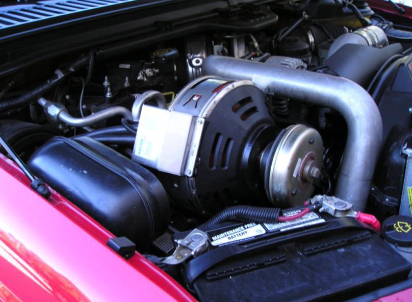
3 General Instructions Torque- This document supplements the Blackbird Wiring Ft-lbs. Manual with information specific to the Ford Grade F-Series and Excursion with the 6.0 diesel engine, single alternator. Contact Raven ( ) if more documentation is needed. Bolt Size 1/ All installation steps must be completed before 5/ / operating the system. 7/ Use Loctite 262 or equivalent on all engine and 1/ bracket mounted bolts, and refer to torque chart for 5/ tightening. 8mm 19 Save all surplus fasteners and OEM clipnuts for reuse 10mm 41 later in the installation 12mm 69 All hoses and wires moved or relocated during 14mm 104 installation must be secured to prevent chafing and exposure to hot surfaces. At no time should wiring be secured to fuel or exhaust system components. NOTE: There is some discrepancy in the distance from the engine block to the nose of the truck in these F-Series chassis. Depending on your chassis, the intercooler tube may seem too long or short fore-and-aft to properly mate with the upper turbo connection. To address this problem, the silicon elbow has extra leg length so that the installer may trim the elbow to get the best fit on the turbo connection. If the engine in your truck is one of the close ones, the distance from the Generator clutch to the passenger s-side battery may be quite small. This condition can be corrected by trimming the fender gusset lightly to allow the battery to move away from the clutch. Preparing for Installation 1. Disconnect both battery negative terminals. 2. Evacuate air conditioning system using approved methods. Disconnect the lines at the accumulator and install the supplied manifold re-positioner on the accumulator. Attach the OEM lines to the re-positioner, and recharge system. Figure Remove passenger side battery. 4. Drain radiator sufficiently, and remove the upper radiator hose, radiator end, and the coolant expansion tank hose at both ends. (The radiator nipple for this hose is subject to breaking when shroud is wiggled out. Careful!) 5. Remove air filter assembly: unplug the MASS air sensor plug from the air inlet housing, and remove the air filter restriction gauge. Loosen the hose clamp at the accordion hose to the engine. Pull the air filter and accordion hose assembly off the engine by wiggling the entire assembly upward and backward. The bottom of the assembly is nested in rubber grommets, and the assembly will swing out once they release. 6. Remove and discard the turbo intercooler pipe. Temporarily plug the intercooler inlet and turbo outlet. Retain the turbo-end silicone connector tube and the OEM clamps. 7. Unplug the fan clutch harness at the upper fan shroud, driver s side. page 2
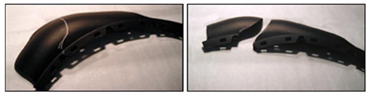
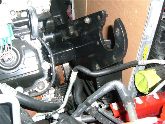
4 8. Cut both sides of the fan shroud at pre-cast parting lines as shown in Figure 4. A hacksaw blade, hot utility knife, or linoleum knife works well. 9. Carefully remove upper fan deflector, deflector gasket, and shroud. Shroud will be reconnected later. 10. Remove the gasket from the upper fan shroud. 11. Tape protective cardboard to the inside of the radiator. 12. Remove the four or five bolts securing the fan stator to the engine, two on top, two on bottom, and in some cases, one on the driver s side. Use a wrench to hold the hex spacer on rear of stator when removing lower two bolts. Note: the upper driver s side bolt will be used later to brace an idler standoff, and the shroud hole will be trimmed back to accommodate the brace. See Step Remove the fan (standard right-hand thread) and allow it to rest in the stator. 14. Carefully lift the fan and stator out together. Set stator aside for trimming before reinstallation See Step Remove the OEM serpentine belt. 16. Remove the OEM belt tensioner. 17. Remove the vacuum canister. Retain the t bolts in the canister for re-use later. Plug the three holes with the supplied retainer buttons. 18. Remove the Glow Plug Relay and bracket from the passenger side valve cover. See Figures 5 and Separate the relay from the bracket and discard the bracket. 20. Install the glow plug relay on the supplied bracket using two truss head screws with flat washers and nylock nuts. Mount the bracket on two OEM alternator bolts. 21. Remove the glow plug power cable from the passenger side battery positive terminal, cut the eye terminal from the end, and extend the cable using the supplied wire and terminals. Reconnect. 22. Remove passenger side battery tray. 23. Remove the windshield washer reservoir. Set aside for return to Raven for core-charge refund. Installing the Raven Crankshaft Pulley, Idlers, and Bracket Figures 1 and 2 below provides an overview of the Raven components (shaded) to be installed and their mounting locations. We suggest you take a minute before proceeding to review the steps below to familiarize yourself with the parts and their mounting locations. 24. Ensure the face of the OEM crankshaft pulley is clean and smooth to allow proper seating of the Raven pulley. 25. Align the three bolt holes and check for proper flush-fit of the Raven pulley on the OEM pulley. Apply Loctite to the three supplied M x 70mm pulley bolts. Using the three supplied flat washers, bolt the Raven pulley to the crank pulley. Tighten bolts sequentially. 26. Remove the Raven belt tensioner and two belt idlers from the Raven bracket. Note position before removing. 27. Inspect the front of the passenger side cylinder head and locate four M10 threaded holes as shown on Figure 2. Assure that these holes and the face of the head are clean and free of debris. Place the Raven bracket over the holes and secure with the supplied M10 x 30mm bolts and lock washers, being careful to clear all wires. Note: 2007 trucks may encounter a modified air conditioning tube routing, causing a kink as in Figure 13. Carefullyl bend the metal portion of the tube to create clearance for the bracket. page 3
5 28. Reinstall the OEM belt tensioner and serpentine belt. 29. Reinstall the Raven belt tensioner and two idlers on the Raven bracket. 30. Install the supplied 6-rib idler and braced standoff assembly to the front of the engine as shown on Figure 2. The assembly brace will sandwich between the fan stator and the engine front cover at the upper stator mounting hole on the driver s side. Insert the flanged bushing into the idler so that the flange faces the bolt and lockwasher. Loctite and install the braced idler assembly to the machined boss on the coolant return section of the coolant manifold just above the fan pulley. Leave bolt loose. Using an OEM stator mounting bolt, bolt the idler brace to the upper stator mounting hole on the coolant manifold, driver s side. Hand tighten this bolt. Now tighten the M10 x 110 standoff bolt. The OEM stator bolt can now be removed in preparation for reinstalling the stator. Note: The stator must be modified at this location by cutting off the metal spacer on this stator mount hole so it is flush with the plastic, allowing room for the idler standoff brace to sandwich between the stator and engine. See Step Install the lower 6-rib idler and standoff assembly on the front of the engine, driver s side. See Figure 2. Mounting the Generator Before mounting the Generator, bench-fit the clutch and key to the Generator shaft. Dress as necessary for a slip fit. 32. Ensure that the generator electrical junction box cover is securely in place. Insert the 3/8 temporary alignment stud finger tight in one threaded hole of the generator bearing plate (shaft end.) 33. Orient the electrical box at approximately 9 o clock. Position the generator above the bracket and slip the generator into the bracket, inserting the temporary alignment stud into one of the four countersunk fastener holes. Assure that the large generator alignment ring machined into the bearing plate is seated fully in the large bracket hole. Install the three 3/8 16 X ¾ flat head generator bolts, and replace the temporary alignment stud with the 4th bolt. Do Not Loctite! Installing the Clutch and Belt 34. Install the electric clutch on the generator shaft insuring that the key aligns with the shaft keyway and the cutout in the outer hub. Pass the supplied serpentine belt over the clutch pulley and start the electric clutch onto the generator shaft insuring that the key aligns with the keyways and the cutout in the outer hub. 35. Engage the open slot or the oval hole (your choice) in the clutch flange with the coil retaining standoff, slide the clutch home on the shaft and fasten with the 7/16-20 bolt and lockwasher. Note: the belt routes between the clutch pulley and the coil retaining standoff mounted on the bracket. 36. Route and install the generator belt according to Figures 1 and 5. Reinstalling the Battery and Windshield Washer Bottle 37. Modify the existing battery tray by drilling out spot welds using a 3/8 drill bit as shown in Figure 6. This will separate the angle bracket from the tray. This angle bracket will be reinstalled at the other end of the tray in the final step of this procedure. page 4
6 38. Insert the modified Windshield Washer bottle in its original position below Battery tray. The modified filler neck will attach to the radiator brace with the supplied self-drilling screw 39. Temporarily reinstall the angle bracket (removed in step 38.) back on the inner fender using the original bolts. Keep the bracket as low as the slotted holes allow. 40. Remove the three clipnuts from the lower battery tray bracket and set aside. Place the battery tray angled approx 45 degrees to locate the battery in line with the corner gusset between the fender and the radiator cross member. This will require bending the inboard corner of the tray slightly to accommodate its new position on the battery tray bracket See Figure 8. Note tray has been rotated 180 degrees to position the battery hold-down on the inboard side. Temporarily insert two original tray bolts to hold the tray in place, one in the lower bracket and one in the angled bracket and set the battery on the tray. The battery should be parallel with and close to the fender gusset. See Figures 7 and 8. Continue trying combinations of the numerous holes in the tray until two line up with the lower bracket and angled bracket when the battery is in position. Secure the tray to the angled bracket with an OEM bolt and a supplied flange nut under the bracket. Maintain the position of the bracket to the tray and remove the assembly from the inner fender. The angled bracket has a second hole in its flange. Drill the tray at this point to locate a second mounting bolt and flange nut in the angled bracket. Reinstall the entire tray assembly and check final fit for the battery. Install rubber edge guard to protect the fender gusset from chafing the edge of the battery. See note on page In some cases the lower battery tray flange may need to be bent up slightly to allow clearance for the intercooler tube elbow. This can be done when the elbow is being installed (Figure 7.) Excursion Installations: Before installing the battery, shift the vacuum solenoid on the passenger-side inner fender forward by moving the rear bolt to the front hole and securing the front with one of the self drilling screws supplied. This assures room for relocating the vacuum canister. See Figure 9. Final Assembly- Fan, Stator, and Shroud 42. Discard the pad from the fan stator, if present. 43. Using the cardboard template supplied, trim the fan stator to accommodate the new belt train. The bolt pattern for aligning the template is non-symmetric, so it will line up only one way. You will be trimming a substantial amount of the stator away. See Figure Cut off the metal spacer on the upper driver s side stator mounting standoff, allowing room for the idler standoff brace added in Step 30, to sandwich between the stator and engine. A hacksaw or zipwheel works well. 45. Reinstall the stator using the OEM stator bolts. 46. Reinstall the fan. 47. Remove cardboard from radiator. 48. Reinstall the upper fan shroud and fasten at the cut lines with the plastic-tapping screws supplied. 49. Reinstall the upper radiator hose, and the expansion tank hose, and refill the radiator. 50. Install the replacement intercooler tube (See note on page 2). Lightly sand the mating areas of the tube and clean with solvent. Clean the interior of the replacement elbow and upper connector with acetone or alcohol until the rubber feels tacky. page 5
7 Use the elbow and large clamp supplied in place of the straight connector hose at the intercooler end. Thoroughly clean the turbo outlet nipple and the intercooler inlet nipple with acetone or alcohol until they are completely void of oil or residue. Place the replacement lower tube clamps on the elbow. Install the tube elbow on the nipple until it contacts the cast-in stops on the nipple. Do not tighten the clamp at this time. Install the intercooler tube in the elbow. Do not tighten.. There is some discrepancy in the distance from the engine block to the nose of the truck in these F-Series chassis. Depending on your chassis, the intercooler tube may seem too long or short fore-and-aft to properly mate with the upper turbo connection. If so, the lower elbow can be adjusted or trimmed to assure proper alignment. Install the upper hose and clamps, assuring that the ridges cast inside the hose mate properly with the reverse features on the pipe and nipple. Assure that the clamp is in position as indicated on the hose. Adjust the tube position relative to engine compartment interferences and tighten all hose clamps to 9 foot pounds. DO NOT OVERTIGHTEN. 51. Remove the long leg from the Ford vacuum canister and relocate the vacuum canister on inner fender as shown in Figure 12 using the Raven bracket, two surplus clip nuts and bolts frpm the battery tray, and two t bolts saved from the canister removal. Excursion: one bracket mount may be sandwiched on the rear vacuum solenoid screw which was moved forward in a previous step. 52. Reconfigure vacuum hoses by cutting the hard plastic tubing in two places and extending it using the supplied extension tubing. 53. Reinstall passenger-side battery on modified tray. 54. Trim upper air deflector an inch or so as in Figure 11 to clear the belt and reinstall. 55. Locate the blue wire exiting the fan clutch plug, engine side. Tap into this wire with the tap-in connector from the supplied Fan Lock-up Harness. Plug the harness into the side of the connector and route the harness to the Command Module (See Blackbird Wiring Manual). 56. Reconnect the fan clutch wiring harness. 57. Plug the Raven clutch harness into the clutch and route it to the Command Module. Leave the thermal fuse free to be incorporated in the Generator wiring. This completes the mechanical installation. Refer to the Blackbird Wiring Manual for electrical wiring, run up, and troubleshooting instructions. page 6


8 Blackbird Installation Supplement for Ford F-Series and Excursion 6.0. Liter Diesel Braced Idler Lower Idler Figure 1 Figure 3 Figure 2 Figure 4 Figure 6 Figure 5 page 7


9 Figure 7 Figure 8 Figure 10 Figure 9 Figure 11 Figure 13 Figure 12 page 8
BLACKBIRD INSTALLATION SUPPLEMENT
 BLACKBIRD INSTALLATION SUPPLEMENT FOR 2003-7 FORD 6.0 LITER DIESEL F-SERIES DUAL ALTERNATOR VERSION 10/07 Blackbird Installation Supplement for Ford 6.0. Liter Dual Alternator Parts included in the 6.0
BLACKBIRD INSTALLATION SUPPLEMENT
 BLACKBIRD INSTALLATION SUPPLEMENT 2008 GM 2500 AND 3500 6.6 DURAMAX DIESEL VERSION 5-08 Parts Included in Installation Kit Before beginning installation, check the parts kit thoroughly against the parts
BLACKBIRD INSTALLATION SUPPLEMENT
 BLACKBIRD INSTALLATION SUPPLEMENT FOR5.3 AND 6 LITER VORTEC SUBURBAN/YUKON/SILVERADO VERSION 2-06 Blackbird Installation Supplement for GM 5.3 and 6 liter Vortec-Suburban/Silverado Parts Included in Installation
BLACKBIRD INSTALLATION SUPPLEMENT
 BLACKBIRD INSTALLATION SUPPLEMENT FOR 2008-105 FORD 6.4 LITER DIESEL F-SERIES VERSION 3/10 Parts Blackbird Wiring Manual Installation Supplement 6.4 liter Diesel Owner s Manual Includes Warrantee Registration
FMK265SD F L DIESEL WITH DUAL ALTERNATORS
 WITH DUAL ALTERNATORS This kit will NOT work on trucks equipped with adaptive steering. INSTALLATION NOTES 1. Disconnect negative batteries cables. Remove the air duct from the passenger side and the black
Subaru Front Mount Intercooler Kit STI Subaru Front Mount Intercooler Kit STI
 Subaru Front Mount Intercooler Kit STI 2008-2014 715500 Subaru Front Mount Intercooler Kit STI 2008-2014 Congratulations on your purchase of the Subaru Front Mount Intercooler Kit STI 2008-2014. The following
DewEze Clutch Pump Kit Ford 6.2L Gas, A Pump, Side Port, 2011+
 DewEze Clutch Pump Kit 700512 Ford 6.2L Gas, A Pump, Side Port, 2011+ INSTALLATION INSTRUCTIONS 1. The installation of this kit requires trained decisionmaking concerning clearances, tying components together,
DewEze Clutch Pump Kit Ford 6.2L Gas, A Pump, Side Port, INSTALLATION INSTRUCTIONS 1. The installation of this kit requires trained decis
 DewEze Clutch Pump Kit 700564 Ford 6.2L Gas, A Pump, Side Port, 2014+ INSTALLATION INSTRUCTIONS 1. The installation of this kit requires trained decisionmaking concerning clearances, tying components together,
1996 Aerostar/Ranger/Explorer
 Page 1 of 11 Section 03-01B: Engine, 3.0L V-6 IN-VEHICLE SERVICE 1996 Aerostar and Ranger Vehicles Workshop Manual Water Pump SPECIAL SERVICE TOOL(S) REQUIRED Description Tool Number Fan Clutch Holding
REMOVAL & INSTALLATION
 REMOVAL & INSTALLATION NOTE: For reassembly reference, label all electrical connectors, vacuum hoses and fuel lines before removal. Also place mating marks on engine hood and other major assemblies before
INSTALLATION INSTRUCTIONS 97 FORD EXPEDITION
 INSTALLATION INSTRUCTIONS 97 FORD EXPEDITION 1. Read the instructions completely and carefully before you begin. Check the kit for proper contents (refer to the part s list and the picture diagrams). Before
Instant Chat off the main page of Or simply call our tech team at
 FRONT MOUNT INTERCOOLER 2015+ WRX 2017-07-07 Thank you for purchasing this PERRIN product for your car! Installation of this product should only be performed by persons experienced with installation of
BD Venom Dual Fuel F O R D 6. 7 L P O W E R S T R O K E Installation Instructions
 U 30 January 2017 (1050470) Venom Dual Fuel Kit (I-00390) 1 DOWNLOAD ENHANCED INSTALL MANUALS AT dieselperformance.com BD Venom Dual Fuel 2 0 1 1-2 0 1 4 F O R D 6. 7 L P O W E R S T R O K E Installation
Instant Chat off the main page of Or simply call our tech team at
 FRONT MOUNT INTERCOOLER 2008-13 STI 2014-04- 08 Thank you for purchasing this PERRIN product for your car! Installation of this product should only be performed by persons experienced with installation
 Page 1 of 6 Section 03-01C: Engine, 7.5L MFI 1996 Bronco/F-Series Workshop Manual IN-VEHICLE SERVICE Procedure revision date: 06/19/2000 Cylinder Heads Removal SPECIAL SERVICE TOOL(S) REQUIRED Description
Procharger Stage II Intercooled Supercharger System (11-14 GT)
") Procharger Stage II Intercooled Supercharger System (11-14 GT) Installation Time: Approximately one day. Installed on 2012 Mustang GT 5.0/Manual Required Tools 3/8 Socket Set (Standard and Metric) 1/2
Procharger Stage II Intercooled Supercharger System (11-14 GT) Installation Time: Approximately one day. Installed on 2012 Mustang GT 5.0/Manual Required Tools 3/8 Socket Set (Standard and Metric) 1/2
Installation Instructions
 2011-2013 LML DURAMAX COMPOUND-ADD 2011-2015 LML A Duramax TURBO KIT Add INSTALL A Turbo INSTRUCTIONS Compound Kit Installation Instructions 1-800-955-0476 - www.industrialinjection.com - info@industrialinjection.com
Installation Instructions Street Bandit Shifter
 Installation Instructions Street Bandit Shifter Part Number 80797 (see www.bmracing.com for the latest technical product information) 2006, 2000 by B&M Racing and Performance Products The B&M Street Bandit
2017+ L5P Duramax 3 ½ Down Pipe & EGR Fix Kit
 2017+ L5P Duramax 3 ½ Down Pipe & EGR Fix Kit Covers installation of PN s: WCF100630, WCF100829 Note: This Kit is for off road competition use only! Off Road Competition Use Tuning & Exhaust System is
2006 Honda Civic SI Supercharger Kit Installation Instruction Kit #
 2006 Honda Civic SI Supercharger Kit Installation Instruction Kit #350-091 3239 MONIER CIRCLE, STE.5 RANCHO CORDOVA, CA 95742 916.635.4550 FAX 916.635.4632 www.ct-engineering.com INS-157 VERSION: 3.25.2009
BD Venom Dual Fuel F O R D 6. 7 L P O W E R S T R O K E Installation Instructions
 U 21 March 2017 (1050470) Venom Dual Fuel Kit (I-00390) 1 DOWNLOAD ENHANCED INSTALL MANUALS AT dieselperformance.com BD Venom Dual Fuel 2 0 1 1-2 0 1 6 F O R D 6. 7 L P O W E R S T R O K E Installation
Ford 6.0L. Part #: Part #: BD GASKET PART# will be needed for this installation.
 1 BD EGR COOLER 2003-2007 Ford 6.0L Part #: 1090201 Part #: 1090202 PLEASE READ ALL INSTRUCTIONS BEFORE INSTALLATION BD GASKET PART# 1090002 will be needed for this installation. 2 K I T C O N T E N T
Scion FR-S ZN6. GTX2867R Gen2 (Internal Wastegate) Installation Instructions GPP P/N #
 Installation Instructions GPP P/N #") TURBO KIT Scion FR-S ZN6 Subaru BRZ ZC6 GTX2867R Gen2 (Internal Wastegate) Installation Instructions GPP P/N # 11518000 Vehicle Type Chassis Code Engine Code Transmission Model Year Scion FR-S DBA-ZN6
TURBO KIT Scion FR-S ZN6 Subaru BRZ ZC6 GTX2867R Gen2 (Internal Wastegate) Installation Instructions GPP P/N # 11518000 Vehicle Type Chassis Code Engine Code Transmission Model Year Scion FR-S DBA-ZN6
Steeda S197 Mustang Whipple Supercharger Drive
 Steeda S197 Mustang Whipple Supercharger Drive Parts List Qty. Description 1 Whipple supercharger snout 1 Whipple snout collar 1 10-rib supercharger pulley 1 10-rib crank pulley 1 10-rib belt tensioner
MAZDASPEED3 Intercooler Instructions
 MAZDASPEED3 Intercooler Instructions Congratulations on your purchase of the COBB Tuning Front Mount Intercooler System for your 2007-2009 Mazdaspeed3. The following instructions should assist you through
4 December 2017 PN# , , Dodge 6.7L Rumble B SXE (I-00400) 1. BD Rumble B SXE. D o d g e 6. 7 L H P C R Installation Instructions
 1. BD Rumble B SXE. D o d g e 6. 7 L H P C R Installation Instructions") 4 December 2017 PN#1045705, 1045706, 1045708 Dodge 6.7L Rumble B SXE (I-00400) 1 DOWNLOAD ENHANCED INSTALL MANUALS AT dieselperformance.com BD Rumble B SXE D o d g e 6. 7 L H P C R Installation Instructions
4 December 2017 PN#1045705, 1045706, 1045708 Dodge 6.7L Rumble B SXE (I-00400) 1 DOWNLOAD ENHANCED INSTALL MANUALS AT dieselperformance.com BD Rumble B SXE D o d g e 6. 7 L H P C R Installation Instructions
BD TrackMaster S D o d g e H P C R Installation Instructions
 7 July 2016 PN#1045701, 1045702, 1045704 Dodge 6.7L TMS400 (I-00361) 1 BD TrackMaster S400 2008-2012 D o d g e H P C R Installation Instructions 1045701 2008-2009 Dodge 6.7L TMS400 1045702 2010-2012 Dodge
Installation Instructions Z-Gate Shifter
 Installation Instructions Z-Gate Shifter Part Number 80681 1998, 2001 by B&M Racing and Performance Products The B&M Z-Gate shifter can be used in vehicles equipped with most popular three speed automatic
Powerstroke 6.4L EGR Block Kit
 Read instructions thoroughly before proceeding! ***This kit may void factory warranty please check with manufacturer.*** You will need the following tools for this installation: 10mm wrench 13mm wrench
XDP Complete EGR Race Track Kit w/up-pipe. Item Number: XD144
 XDP Complete EGR Race Track Kit w/up-pipe Item Number: XD144 PACKING LIST: 2 - Lined 3/4" SS Hose Clamp 1-3/4 Silicone Hose 1 - XDP Engraved EGR Valve Block-Off Plate with O-ring 1 - EGR Cooler Block-Off
2015+ SUBARU STI FRONT-MOUNT INTERCOOLER PARTS LIST AND INSTALLATION GUIDE INSTALL DIFFICULTY DISCLAIMER CAUTION INSTALL PROCEDURE TOOLS NEEDED
 PARTS LIST AND PARTS INCLUDED 1PC ALUMINUM INTAKE PIPE 1PC BAR-AND-PLATE INTERCOOLER 1PC STEEL CRASH BAR W/ MOUNTING HARDWARE 2PC HOT-SIDE INTERCOOLER PIPES 2PC COLD-SIDE INTERCOOLER PIPES 1PC BPV FLANGE
LPE C5 Battery Relocation Kit
 LPE C5 Battery Relocation Kit The LPE C5 Corvette battery relocation kit improves vehicle weight distribution by moving weight to the rear of the vehicle. The improved weight distribution increases traction
Ford E350, E450 Van LITER DIESEL ENGINE W/SINGLE OE ALTERNATOR TYPE B Uses TM-16, 4-3/4 Poly Groove Rear Port Compressor PARTS LIST
 2006-04 Ford E350, E450 Van 1784 6.0 LITER DIESEL ENGINE W/SINGLE OE ALTERNATOR TYPE B Uses TM-16, 4-3/4 Poly Groove Rear Port Compressor PARTS LIST 1 6m-1.0 x 15 Bolt 1 6m-1.0 x 45 Bolt 3 6m Flat Washer
4. Remove (4) 10mm and (1) 7mm bolt that holds fascia at front corners, on each side
 10mm and (1) 7mm bolt that holds fascia at front corners, on each side") 2010 Camaro LS3 1. Disconnect battery ground 2. Remove front wheels 3. Remove (5) push pins and (5) #20 torx screws on inner front wheel well liners and remove liners on each side 4. Remove (4) 10mm and
2010 Camaro LS3 1. Disconnect battery ground 2. Remove front wheels 3. Remove (5) push pins and (5) #20 torx screws on inner front wheel well liners and remove liners on each side 4. Remove (4) 10mm and
Ford F-100 Evaporator Kit (751153)
") an ISO 9001:2015 Registered Company 1968-72 Ford F-100 Evaporator Kit (751153) 18865 Goll St. San Antonio, TX 78266 Phone: 800-862-6658 Sales: sales@vintageair.com Tech Support: tech@vintageair.com www.vintageair.com
an ISO 9001:2015 Registered Company 1968-72 Ford F-100 Evaporator Kit (751153) 18865 Goll St. San Antonio, TX 78266 Phone: 800-862-6658 Sales: sales@vintageair.com Tech Support: tech@vintageair.com www.vintageair.com
GM LS Series Serpentine Drive System with & without Power Steering
 an ISO 9001:2015 Registered Company GM LS Series Serpentine Drive System with & without Power Steering 18865 Goll St. San Antonio, TX 78266 Phone: 800-862-6658 Sales: sales@vintageair.com Tech Support:
Air Commander Part No
 EASYSTEET Air Commander Part No. 26903 www.airliftcompany.com MN-510 (06506) EC 5206 Please read these instructions completely before proceeding with installation The oil level in the compressor must be
Photo 1. Shift pattern gate plate
 Installation Instructions MAGNUM GRIP STREET BANDIT SHIFTER Fits: GM, Chrysler, and Ford Automatic Transmissions See Application Guide for Specific Vehicles Catalog # 81050 WORK SAFELY! For maximum safety,
Included parts: 1 - New Bosch CP3 Pump 1 - HSM Pulley 1 - Serpentine Belt 1 - Pump Brackets/Hardware
 TROUBLESHOOTING: Please read and understand all installation instructions before proceeding with the installation. If you have questions during the installation of this product, please email H&S Motorsports
IAG Air / Oil Separator (AOS) For STi
 For STi") IAG Air / Oil Separator (AOS) For 2008-14 STi Part# IAG-ENG-7000 Tools Required: Ratchet, torque wrench, extensions, needle nose pliers, hose cutter, snips/scissors Sockets: 10mm, 12mm 13mm Wrenches: 10mm,
IAG Air / Oil Separator (AOS) For 2008-14 STi Part# IAG-ENG-7000 Tools Required: Ratchet, torque wrench, extensions, needle nose pliers, hose cutter, snips/scissors Sockets: 10mm, 12mm 13mm Wrenches: 10mm,
Cut zip ties and remove 2 plastic wiring harness brackets.
 TROUBLESHOOTING: Please read and understand all installation instructions before proceeding with the installation. Included parts: 1 - New Bosch Cp3 Pump 1 - HSM Pulley 1 - Serpentine Belt 1 - Pump Bracket/
WATER PUMP INSTALLATION INSTRUCTIONS WEIAND WATER PUMPS ACTION PLUS & TEAM G APPLICATIONS FOR SMALL BLOCK & BIG BLOCK CHEVROLETS
 WATER PUMP INSTALLATION INSTRUCTIONS WEIAND WATER PUMPS ACTION PLUS & TEAM G APPLICATIONS FOR SMALL BLOCK & BIG BLOCK CHEVROLETS APPLICATIONS: Weiand Action Plus aluminum water pumps are designed for street/performance
Mercedes E63/CLS AMG Carbon Turbo Intake System Instructions
 Mercedes E63/CLS AMG Carbon Turbo Intake System Instructions The goal of Alpha Performance is to provide the highest quality, best performing products available. By utilizing research and development,
Installation Manual v1.0: MST Turbo Kit ( ) 5.9L Dodge. Please read all instructions before installation.
 5.9L Dodge. Please read all instructions before installation.") Installation Manual v1.0: MST Turbo Kit (2003-2007) 5.9L Dodge Please read all instructions before installation. Figure 1: MST Kit Contents Figure 2: MST Hardware Kit Please make sure all of the components
Installation Manual v1.0: MST Turbo Kit (2003-2007) 5.9L Dodge Please read all instructions before installation. Figure 1: MST Kit Contents Figure 2: MST Hardware Kit Please make sure all of the components
Banks Techni-Cooler Intercooler Assembly Ford Power Stroke 6.0L Turbo-Diesel F250/F350/F450/F550 Trucks & Excursions
 Owner smanual with Installation Instructions Banks Techni-Cooler Intercooler Assembly 2003-2007 Ford Power Stroke 6.0L Turbo-Diesel F250/F350/F450/F550 Trucks & Excursions THIS MANUAL IS FOR USE WITH SYSTEMs
Ford 6.8L, w/spider, 2000+
 DewEze Aiir Compressor Kiit 700554 Ford 6.8L, w/spider, 2000+ INSTALLATION INSTRUCTIONS 1. Disconnect the battery. 2. Drain the radiator. 3. Remove the air cleaner assembly. 4. Remove the upper radiator
2015 Corvette Supercharger System Instructions
 2015 Corvette Supercharger System Instructions These instructions are meant to serve as a guide to the installation of the ECS 2015 Corvette Supercharging system. Please be sure to use all safety equipment
Do not have any open flame or heat sources close to the installation
 March 6, 2017 IS# 791 Page 1 of 16 Thank you for purchasing a Transfer Flow, Inc. 50-gallon replacement fuel system for your 2011-16 Ford diesel short bed pickup. This system will fit any 2x4 or 4x4 crew
* PLEASE READ INSTRUCTIONS PRIOR TO INSTALLATION
 XDP 6.0L Complete EGR Delete Kit w/up-pipe Item Number: XD169 PACKING LIST: 2 - Lined 3/4" Hose Clamps, 1-180 Coolant Tube, 1-3/4 Silicone Hose, 1 - Stainless Steel Up-pipe 1 - EGR Valve Block-Off Plate,
DODGE DAKOTA 3 BODY LIFT INSTALLATION INSTRUCTIONS KIT # 60153
 DODGE DAKOTA 3 BODY LIFT INSTALLATION INSTRUCTIONS 2003-04 KIT # 60153 Installation of a Performance Automotive Group body lift kit will change the vehicle s center of gravity and handling characteristics
SLP Camaro ZL1 STAGE 3 (650 HP)
") SLP - 2012 Camaro ZL1 STAGE 3 (650 HP) PART #26002 PACKING LIST Before installation, use this check list to make sure all necessary parts have been included. ITEM QTY CHECK PART NUMBER DESCRIPTION 1. 1
SLP - 2012 Camaro ZL1 STAGE 3 (650 HP) PART #26002 PACKING LIST Before installation, use this check list to make sure all necessary parts have been included. ITEM QTY CHECK PART NUMBER DESCRIPTION 1. 1
INSTALLATION INSTRUCTIONS FORD F-150 2WD & 4WD RETAINS FACTORY TOW HOOKS PART #P3063
 INSTALLATION INSTRUCTIONS FORD F-150 2WD & 4WD RETAINS FACTORY TOW HOOKS PART #P3063 PARTS LIST: 1 Grille Guard 2 10-1.5mm Nylon Lock Nuts 1 Driver/Left Frame Mounting Bracket 4 12mm Plastic Washers 1
#TL T EA888 GEN 3 FUELING SYSTEM/ INSTALLATION INSTRUCTIONS
 #TL100069 2.0T EA888 GEN 3 FUELING SYSTEM/ INSTALLATION INSTRUCTIONS Notes: These instructions were written for a North American specification MkVII GTI. Other models, like the Golf R, are similar. When
This information covers the proper procedure for replacing the Volvo D16F engine in a VT or VNL chassis.
 Volvo Trucks North America Greensboro, NC USA Engine, Replacement DService Bulletin Trucks Date Group No. Page 10.2007 210 139 1(47) Engine, Replacement Volvo D16F VNL, VT W2005773 This information covers
ENGINE DEVELOPMENT INC.
 2003 Ford Expedition 4.6L& 5.4L We encourage you to read this manual thoroughly before you begin work, and perform the following: 1. A quick parts check to make certain your kit is complete. If you discover
Installation Instructions for: TOYOTA 3.4L SUPERCHARGER SYSTEM
 Installation Instructions for: TOYOTA 3.4L SUPERCHARGER SYSTEM 1996-2002 4Runner 1997-1998 T100 1997-2004 Tacoma 2000-2003 Tundra * PREMIUM FUEL REQUIRED * Magnuson Products LLC 1990 Knoll Drive, Bldg
Performance Inlet Manifold
 Performance Inlet Manifold Tools needed (some tools not required on some models): 13mm Combination Wrench Flat Blade Screwdriver T30 Torx Driver T25 Torx Driver 10mm Combination Wrench and/or Socket with
INSTALLATION INSTRUCTIONS AIR/OIL SEPARATOR KIT
 INSTALLATION INSTRUCTIONS AIR/OIL SEPARATOR KIT 2015+ SUBARU WRX (LHD ONLY) Document: 19-0136 Support: info@radiumauto.com This document covers the installation of the Radium brake master cylinder brace
Installation Instructions for: TOYOTA 4.5L SUPERCHARGER SYSTEM
 Installation Instructions for: TOYOTA 4.5L SUPERCHARGER SYSTEM 1995-1997 Land Cruiser * PREMIUM FUEL REQUIRED * Magnuson Products LLC 1990 Knoll Drive, Bldg A, Ventura, CA 93003 (805) 642-8833 phone *
VR6 Supercharger System Golf III and Jetta III VR6 Installation Manual Model Year
 VR6 Supercharger System Golf III and Jetta III VR6 Installation Manual Model Year 1994-1999.5 Date 10/28/00 Page 1 Index 1.0 Parts List 1.1 Required Tools 1.2 Required Standard Parts 1.3 Required Misc.
Air Commander Late Model Ford F-150
 EASYSTREET Air Commander Late Model Ford F-150 www.airliftcompany.com MN-544 (02506) ECR 5206 Please read these instructions completely before proceeding with installation The oil level in the compressor
Porsche 928 with 16v LH-Jetronic Fuel System
 Porsche 928 with 16v LH-Jetronic Fuel System Toll-Free Tech Hot Line: 877-FOR-928M 877-367-9286 Please do not copy this manual and give copies to your friends. Our ability to bring you this supercharger
Includes: 1. J-hook Block Off / Coolant Reroute 1. Coolant Hose 1. Turbocharger Up Pipe Block Off Disc 2. Hose clamps
 Includes: 1. J-hook Block Off / Coolant Reroute 1. Coolant Hose 1. Turbocharger Up Pipe Block Off Disc 2. Hose clamps WARNING: This product is not legal for sale or use on pollution controlled vehicles
Light Truck MegaShifter
 Installation Instructions Light Truck MegaShifter The B&M Light Truck Megashifter shifter is designed to be used in most light trucks equipped with most popular three speed or four speed automatic transmissions.
SHELBY GT500
 2007-2009 SHELBY GT500 Removal of Factory Unit WARNING: 1. Radiator fluid must be handled properly. Please observe local ordinances with regards to handling and disposal. 2. Allow vehicle and components
INSTALLATION INSTRUCTIONS FOR COZY CAB A-1 AIR CONDITIONING KIT
 INSTALLATION INSTRUCTIONS FOR COZY CAB A-1 AIR CONDITIONING KIT 05-11 INSTALLATION INSTRUCTIONS A-12235 Air Conditioner Kit Cab set up instructions; This air conditioning kit is designed to be used with
Keeping You Cool Under Pressure
 Installation Instruction for 92-93 GM 6.5L Turbo Diesel Series 3500-4 Wheel Drive Pickup and Series 1500, 2500, 3500 4 Wheel Drive Suburban Intercooler System (Part No. 2-436) TOOLS REQUIRED: 1.) Normal
JODALE PERRY. Parts List & Mounting Instructions. Jacobsen HR9016 JDP BUILT FOR LIFE
 JODALE PERRY Parts List & Mounting Instructions Jacobsen HR9016 JDP BUILT FOR LIFE Jacobsen HR9016 Mounting Instructions Standard Parts 1 - LH Rear Mounting Bracket 1 - RH Rear Mounting Bracket 1 - Front
JBR MAZDASPEED
 Page1 james Barone Racing Aftermarket Parts and Accessories JBR 2007 2009 MAZDASPEED 3 Front Mount Intercooler Piping Kit Installation Instructions for TR8 Intercooler Tooling: o Jack, Jack Stands, Ramps
INSTALLATION INSTRUCTIONS
 HIGH FLOW AIRFLOW METER INSTALLATION INSTRUCTIONS PART NUMBER D763-1600A APPLICATION: 2001-06 E46 M3 Parts List: Hose clamp 64Z (7) Plastic Rivets Air Filter Temp Sensor & Harness (2) Button Head Screws
Step 6: Remove and save the MAP sensor for later use. Step 7: Remove the passenger side intercooler pipe and the EGR intake manifold.
 LBZ Twin kit Install Step 1: Disconnect both batteries. Step 2: Drain coolant and oil also remove passenger side inner fender. Step 3: Remove intake box and piping. (Remove and save the MAF sensor in the
Air Commander
 EASYSTREET Air Commander www.airliftcompany.com MN-507 (03206) ECN 3921 Please read these instructions completely before proceeding with installation. The oil level in the compressor must be checked BEFORE
V1 Truck Manifold Turbo Kit for F-body
 V1 Truck Manifold Turbo Kit for 98-02 F-body Prep: -Remove all A/C Components, Alternator and brackets, tensioner, front bumper, front bumper foam, and front bumper support. Remove radiator and cooling
1. Disconnect the battery. This is important! This will prevent air bag deployment.
 PARTS PACKING LIST Evaporator assembly Drain tube Plastic air plug Hardware package 11040 3601 W. Clarendon Phoenix, Arizona 85019 (602) 233-0090 800-648-4475 www.ackits.com 2003-4 Jeep Wrangler EVAPORATOR
Includes: 1. High Flow Turbo Up-Pipe 1. J-Hook Block Off / Coolant Reroute 1. Coolant Hose 1. EGR Valve Block Off Plate 2. Hose Clamps 4.
 Includes: 1. High Flow Turbo Up-Pipe 1. J-Hook Block Off / Coolant Reroute 1. Coolant Hose 1. EGR Valve Block Off Plate 2. Hose Clamps 4. Bolts & Nuts WARNING: This product is not legal for sale or use
INSTALLATION GUIDE PREMIUM FRONT BUMPER FOR RAM AEV30304AA Last Updated: 09/18/17
 AEV30304AA Last Updated: 09/18/17 PREMIUM FRONT BUMPER FOR RAM 1500 INSTALLATION GUIDE PLEASE READ BEFORE YOU START To guarantee a quality installation, we recommend reading these instructions thoroughly
Installation Instructions. QuickSilver Shifter. Fits: GM, Ford, Chrysler Transmissions See Application Guide for Specific Applications Part # 80683
 Installation Instructions QuickSilver Shifter Fits: GM, Ford, Chrysler Transmissions See Application Guide for Specific Applications Part # 80683 WORK SAFELY! For maximum safety, perform this installation
1994 Ford Mustang - Engine Mechanical > Engine Mechanical Components > Timing Chain Cove...
 Page 1 of 6 1994 Ford Mustang : Engine Mechanical > Engine Mechanical Components > Timing Chain Cover & Seal > Removal & Installation > 5.0L Engine 5.0L Engine 1. Disconnect the negative battery cable
96-04 tt. Hellion Power Systems Mustang Twin Turbo Kit Instructions
 96-04 tt Hellion Power Systems 1996-2004 Mustang Twin Turbo Kit Instructions 1. Disconnect battery and elevate front end of car on either Jack stands or a lift if available 2.Lock steering wheel and remove
INSTALLATION INSTRUCTIONS AOS-R (Air Oil Separator-Return) Turbo Subaru and STi
 Turbo Subaru and STi") INSTALLATION INSTRUCTIONS AOS-R (Air Oil Separator-Return) 02-14 Turbo Subaru and 2015+ STi These instructions are based on a vehicle with an OEM turbocharger and top-mount intercooler. If a front-mount
INSTALLATION INSTRUCTIONS AOS-R (Air Oil Separator-Return) 02-14 Turbo Subaru and 2015+ STi These instructions are based on a vehicle with an OEM turbocharger and top-mount intercooler. If a front-mount
Installation Manual for VMAC System V Ford SuperDuty F250-F L Power Stroke V8
 Installation Manual for VMAC System V910006 2003.25-2007 Ford SuperDuty F250-F550 6.0L Power Stroke V8 General Information... 4 Before You Start... 4 Part 1: Warranty and System ID... 5 Part 2: Preparing
INSTALLATION INSTRUCTIONS
 COLD AIR INTAKE INSTALLATION INSTRUCTIONS PART NUMBER D760-0620 & D760-0621 PARTS LIST APPLICATION: 9/98-2003 E39 540i 4.4L 4" Intake Tube Air Filter w/ clamp Silicone Hose 80-100mm Hose Clamp 90-110mm
WARNING: ALWAYS relieve fuel pressure before disconnecting any fuel related component. DO NOT allow fuel to contact engine or electrical components.
 4.0L V8 - VINS [K,U] Selected Block 1990 Lexus LS 400 For Lextreme Powertrain 2020 S. Hacienda Blvd. # D Hacienda Heights California 91745 Copyright 1998 Mitchell Repair Information Company, LLC Friday,
18SP680Rev3 EPA04 MBE 4000 Car Hauler Low Pressure Fuel Lines
 8SP680Rev3 EPA04 MBE 4000 Car Hauler Low Pressure Fuel Lines KIT DESCRIPTION These service kits include all necessary parts to replace the low pressure fuel lines between the fuel filter housing and fuel
Hurst VMATIC3 INSTALLATION
 FORM 159 8530 07/12 Hurst VMATIC3 3-Speed & 4-Speed Automatic Shifter Catalog #3838530 2012 by Hurst Performance The Hurst Vmatic3 shifter can be used in vehicles equipped with most popular three speed
05-08 GT. Hellion Power Systems Mustang Kit Instructions
 Hellion Power Systems 05-08 Mustang Kit Instructions 1. Disconnect Battery 2. Drain Radiator, keep fluid for re-installation. 3. Remove air box and inlethoses. 6. Next, underneath, punch oil pan for turbo
Exhaust Heat Shield Instructions ND
 Exhaust Heat Shield Instructions ND 2016 + Thank you for purchasing the Track Dog Racing Exhaust Heat Shield for the 2016 to Present Mazda MX-5. Our TDR Heat Shield is designed to help maintain lower temperatures
Z-Gate Universal Shifter
 Installation Instructions Z-Gate Universal Shifter Fits: GM, Ford, Lincoln and Chrysler Transmissions See Application Guide for Specific Applications Part #80681 Rev 06/01/2018 WORK SAFELY! For maximum
Included parts: 1 - New Bosch CP3 Pump 1 - HSM Pulley 1 - Serpentine Belt 1 - Pump Bracket/ Hardware STEP 1
 TROUBLESHOOTING: Please read and understand all installation instructions before proceeding with the installation. If you have questions during the installation of this product, please contact H&S Motorsports
Installation Instructions Unimatic Shifter
 Installation Instructions Unimatic Shifter Universal Shifter for Automatic Transmissions Part Number 80775 2010, 2000 by B&M Racing & Performance Products The B&M Unimatic is a universal shifter that will
INSTALLATION INSTRUCTIONS AOS-R (Air Oil Separator-Return) Turbo Subaru and STi Document# Support:
 Turbo Subaru and STi Document# Support:") INSTALLATION INSTRUCTIONS AOS-R (Air Oil Separator-Return) 02-14 Turbo Subaru and 2015+ STi Document# 19-0102 Support: info@radiumauto.com These instructions are based on a vehicle with an OEM turbocharger
INSTALLATION INSTRUCTIONS AOS-R (Air Oil Separator-Return) 02-14 Turbo Subaru and 2015+ STi Document# 19-0102 Support: info@radiumauto.com These instructions are based on a vehicle with an OEM turbocharger
Parts List See cover Page
 Thank you for purchasing the CorkSport Front Mount Intercooler Kit for the 2010-2013 Mazdaspeed 3. Keep your BAT s under check with the CorkSport FMIC Kit with the small or large intercooler. Please let
Tools Required. Metric Wrench Set Screwdriver Set Metric Socket Set Pliers Heavy duty hydraulic Jack and Car Stands Box knife or similar Hacksaw WD40
 Subaru 2004+ Legacy GT & Outback XT For JDM 2.0 twinscroll turbo and USDM 2.5 turbo models Front Mount Intercooler Fitting Instructions PN# LEG-1348-000 You are now the proud owner of a highly tested and
Air Conditioner for M915 A0/A1 Truck
 RD-2-4530-0 Air Conditioner for M915 A0/A1 Truck INSTALLATION INSTRUCTIONS Install refrigerant compressor per instructions provided with compressor mount kit. CAUTION: Edges of sheet metal can be sharp!
INSTALLATION INSTRUCTIONS DODGE DAKOTA 2 KIT # 682 (2WD), 692 (4WD) 3 KIT # 683 (2WD), 693 (4WD)
, 692 (4WD) 3 KIT # 683 (2WD), 693 (4WD)") INSTALLATION INSTRUCTIONS 1997-1999 DODGE DAKOTA 2 KIT # 682 (2WD), 692 (4WD) 3 KIT # 683 (2WD), 693 (4WD) Installation of a Performance Accessories body lift kit will change the vehicle s center of gravity
INSTALLATION INSTRUCTIONS 1997-1999 DODGE DAKOTA 2 KIT # 682 (2WD), 692 (4WD) 3 KIT # 683 (2WD), 693 (4WD) Installation of a Performance Accessories body lift kit will change the vehicle s center of gravity
INSTALLATION INSTRUCTIONS
 COLD AIR INTAKE INSTALLATION INSTRUCTIONS PART NUMBER D760-0390C APPLICATION: 1999-2003 E39 M5 PARTS LIST 1 Left Aluminum Intake Tube 1 Air Pump Bracket (A) 1 Right Aluminum Intake Tube 1 Air Pump Bracket
Exhaust System Installation Turbo Downpipe Audi MKII TT-RS 2.5T CD100028
 Please take the time to read and understand installation instructions. APR recommends that installation of this system be performed by a qualified service center or professional muffler installer who has
Installation Instructions
 Installation Instructions Transverse K04 Tools Required Jack and jack stands Drain pan for coolant and oil 3" and 6" extensions Channel locks 7mm, 8mm, 10mm, 11mm, 12mm, 13mm, and 16mm sockets Oxygen sensor
Z1 Motorsports 370Z/G37 Oil Cooler Kit Installation Manual
 Z1 Motorsports 2877 Carrollton Villa Rica Hwy Carrollton GA 30116 770.838.7777 Z1 Motorsports 370Z/G37 Oil Cooler Kit Installation Manual For 19, 25 and 34 Row Oil Cooler Kits Parts Included: 1 SETRAB
INSTALLATION INSTRUCTIONS AOS-R (Air Oil Separator-Return) Turbo Subaru and STi Document# Support:
 Turbo Subaru and STi Document# Support:") INSTALLATION INSTRUCTIONS AOS-R (Air Oil Separator-Return) 02-14 Turbo Subaru and 2015+ STi Document# 19-0102 Support: info@radiumauto.com These instructions are based on a vehicle with an OEM turbocharger
INSTALLATION INSTRUCTIONS AOS-R (Air Oil Separator-Return) 02-14 Turbo Subaru and 2015+ STi Document# 19-0102 Support: info@radiumauto.com These instructions are based on a vehicle with an OEM turbocharger