Cat. RK 47-2 E CASE AND MOUNTING. January 1967 DESIGN AND MODE OF OPERATION
|
|
|
- Mitchell Nigel Greer
- 5 years ago
- Views:
Transcription
1

2 The RIDA relay is a time-lag over-current relay whose operating time is independent of the current. The relay is available with different current scales for 50 Hz with the time-lag scale s and for 60 Hz with the time-lag scale s. The RIDA relay is a time-lag over-current relay whose operating time is independent of the current. The relay is available with different current scales for 50 Hz with the time-lag scale s and for 60 Hz with the time-lag scale s.
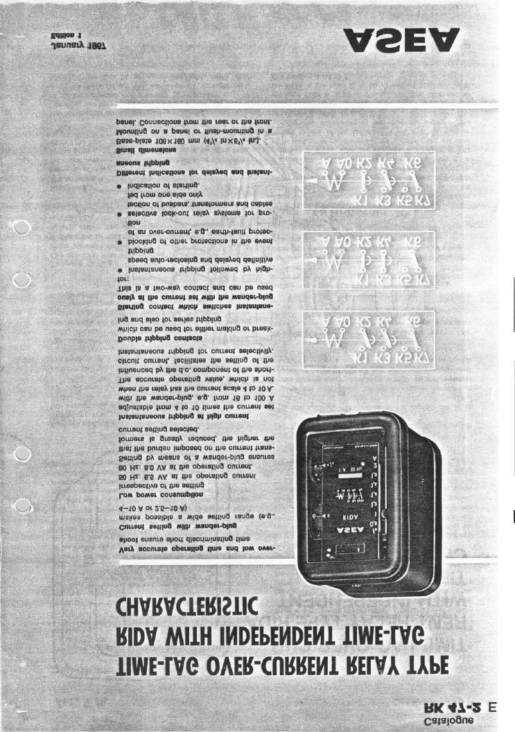
3 Cat. RK 47-2 E DESIGN AND MODE OF OPERATION The figure on page 2 shows the design of the relay. When the current attains the value set with the wanderplug F on the plug bridge E, the armature H picks up. As soon as this occurs, the rotor G of the synchronous motor is released and starts to drive the differential gearing. The pin R starts to rotate at a low speed in comparison with that of the gear-wheel T. After a certain time, which is slightly less than that set on the time-lag scale, the.toothed seg- ment S is made to engage the gearwheel T by the pin R. The carrier B, which is linked with the toothed segment, actuates at great speed the contacts K1-K2 and K3-K4 at the instant corresponding to the set time. The relay has another armature C, which picks up if the current attains the va!ue set with the knurled wheel J. This current is a multiple of the value set with the wander- plug F. The toothed segment S is made to engage direct the gear-wheel T so that the contacts switch instantane- ously. The advantage of this arrangement is that the excess energy of the motor is utilised for operating the contacts, thereby relieving the burden on the instantaneous armature C and keeping the power consumption of the relay at a low value. Current setting The relay can be set to different current values by inserting the wander-plug F in the appropriate socket in the plug bridge E so that different numbers of turns in the relay coil are connected. When the plug is withdrawn altogether, the relay is set to its highest operating current. This enables reconnection to be made interruption-free while the relay is in service without any risk of opening the secondary winding of the current transformers. The advantage of current setting with a wander-plug over spring setting is that the burden imposed on the current transformers will be the lowest possible for each current setting (see the table on page 6 and 7) and that the instantaneous operation can be set as a multiple of the current setting (see below). Time-lag setting The operating time is set with a knurled wheel P, which alters the angle through which the pin R has to turn before it allows the toothed segment S to engage the gear-wheel T. This setting can also be altered while the relay is in service. Resetting The armature H resets ins tantaneously if the current drops below 85 per cent of the set value. The differential gearing then also resets rapidly to the initial position determined by the time-lag setting for the pin R and, at the same time, causes the motor to stop. Instantaneous operation The relay can be set to operate instantaneously by means of the knurled wheel J at a current corresponding to 4-10 times the value set with the wander-plug F. Instantaneous operation can thus be set within very wide limits, e.g., January 1967 for a relay with the current scale 4-10 A from 4X4=16 A up to 1OX10=100 A. The instantaneous operation is blocked if the wheel is set to oo. When the relay is used for series tripping and there is a likelihood of high currents, instantaneous tripping should always be used in view of the limited current-carry- ing capacity of the contacts. The operating value of the instantaneous tripping is practically independent of the d.c. component of the short-circuit current. Dependence on harmonics In the event of a large over-current, saturation in the current transformers may give rise to harmonics in the secondary current, above all the third harmonic. However, this phenomenon affects neither the operating time nor the instantaneous tripping of RIDA. The operating current may be slightly affected if the harmonic content is above 20 per cent, but saturation in the current transformers can scarcely occur for such small currents as 1 to 2 times the normal current, for example. Contacts The relay has two contacts, K1-K2 and K3-K4, which switch after the set time-lag. They are normally make contacts, but can be altered to break contacts by removing the fixed contact member and placing this beneath the moving contact member. When series tripping with high currents is required, both contacts should be connected in parallel (as break contacts) and protective resistors of type MXAA should be used, the MXAA is described in Cat. RK47-1 E. See also the note in the table for the contact data on page 5. In addition, the relay is fitted with a two-way contact K5- K6-K7, known as the starting contact, which is actuated directly by the armature H without any time-lag. Indication If the relay has operated after a time-lag, this is indicated by means of a red flag marked with 1 hole. If the relay operates instantaneously as a result of a large overcurrent, other part of the flag marked with 2 holes becomes visible. The flag can be reset by means of a pushbutton. CASE AND MOUNTING The RIDA relay is mounted on a base of black insulating material and has a dust-proof, black-enamelled aluminium cover with door and window. The terminals are at the rear of the base and the relay is intended to be mounted on a panel with connections at the rear. Fixing bolts for a panel up to 5 mm thick are supplied with the relay. The cover and other non-current-carrying metal parts are con- nected to one of the two fixing bolts and can thus be earthed. The dimensions of the relay are shown in the dimension drawings on page 8. Accessories: Flush-mounting frame, if the relay is to be mounted flush in a panel. Fixing plate with terminals on the front, if the relay is to be connected from the front. See Catalogue RK 93 E. 3

4 3

5

6 ASEA ORDERING TABLES 50 Hz 6

7
8
Inverse-Time Overcurrent & E/F Relays. Type ICM 21, ICM 21B. Station Automation & Protection. ABB Substation Automation Products
 Station Automation & Protection Inverse-Time Overcurrent & /F Relays Type ICM, ICM B ABB Substation Automation Products Features the driving solenoid has tappings, corresponding to the seven stages of
3.0 CHARACTERISTICS E Type CO-4 Step-Time Overcurrent Relay
 41-106E Type CO-4 Step-Time Overcurrent Relay A core screw accessible from the top of the switch provides the adjustable pickup range. The IIT contacts are connected in the trip circuit to trip instantaneously.
Type CDG 14 Extremely Inverse Time Overcurrent and Earth Fault Relay
 Type DG 14 Extremely Inverse Time Overcurrent and Earth Fault Relay Type DG 14 Extremely Inverse Time Overcurrent and Earth Fault Relay DG 14 drawn out from the case The type DG 14 relay is a heavily damped
Type DTH 31, 32 DTTM 11, 12 High Speed Biased Differential Relays
 Type DTH 31, 32 DTTM 11, 12 High Speed Biased Differential Relays Type DTH 31, 32 DTTM 11, 12 High Speed Biased Differential Relays DTH relay withdrawn from case Features l High speed. l Low burden. l
The galvanic separation of the primary or actuating circuit and the load circuits
 RELAY BASICS Relays are electro magnetically operated switches. An actuating current on a coil operates one or more galvanically separated contacts or load circuits. The electro mechanical relay is a remote
ABB ! CAUTION. Type KRV Directional Overcurrent Relay E 1.0 APPLICATION 2.0 CONSTRUCTION AND OPERATION. Instruction Leaflet
 ABB Instruction Leaflet 41-137.2E Effective: February 1994 Supersedes I.L. 41-137.2D, Dated February 1973 ( )Denotes Change Since Previous Issue. Type KRV Directional Before putting relays into service,
Inverse-Time Overcurrent & E/F Relays. Type ICM 21, ICM 21B
 Inverse-Time Overcurrent & E/F Relays Type ICM 21, ICM 21B ABB a global technology leader ABB is a global leader in Power and Automation technologies that enable utility and industry customers to improve
B CW POWER RELAY
 41-241.31B CW POWER RELAY nected in such a way that current, (I A ), leads voltage, (V BA ), by 150 degrees when the motor is operating at unity power factor. Loss of excitation to the motor causes a large
Type SOQ Negative Sequence Time Overcurrent Relay
 ABB Power T&D Company Inc. Power Automation & Protection Division Coral Springs, FL Allentown, PA April 1998 Supersedes DB dated August 1991 Mailed to: E,D, C/41-100B For Protection of Rotating Machinery
2.0 CONSTRUCTION AND OPERATION 3.0 CHARACTERISTICS K. CO (HI-LO) Overcurrent Relay
 Overcurrent Relay") 41-100K 2.0 CONSTRUCTION AND OPERATION The type CO relays consist of an overcurrent unit (CO), either an Indicating Switch (ICS) or an ac Auxiliary Switch (ACS) and an Indicating Instantaneous Trip unit
41-100K 2.0 CONSTRUCTION AND OPERATION The type CO relays consist of an overcurrent unit (CO), either an Indicating Switch (ICS) or an ac Auxiliary Switch (ACS) and an Indicating Instantaneous Trip unit
CHAPTER 4 PROTECTION REQUIREMENTS
 CHAPTER 4 PROTECTION REQUIREMENTS CHAPTER 4 PROTECTION REQUIREMENTS 4.1 General Means of protection for automatic disconnection against phase and earth faults shall be provided on the customer main switch.
HGA. Hinged Armature Auxiliary. Hinged armature auxiliary relay to perform auxiliary functions in AC and DC circuits.
 HA Hinged Armature Auxiliary Hinged armature auxiliary relay to perform auxiliary functions in and circuits. eatures and Benefits Molded case with 4 mounting options Drawout case available Applications
A - Add New Information C - Change Existing Information D - Delete Information. Page 7. Delete the fourth paragraph beginning CAUTION
 ABB Effective: November 1990 This Addendum Supersedes all Previous Addenda Addendum to Instruction Leaflet 41-137.3H Type KRD-4 Directional Overcurrent Ground Relay A - Add New Information C - Change Existing
Legal Name of the Customer (or, if an individual, individual's name): Name: Contact Person: Mailing Address: Physical Address: City: State: Zip Code:
: Name: Contact Person: Mailing Address: Physical Address: City: State: Zip Code:") Generating Facility Level 2 or 3 Interconnection Review (For Generating Facilities with Electric Nameplate Capacities no Larger than 20 MW) Instructions An Interconnection Customer who requests a Utah
Generating Facility Level 2 or 3 Interconnection Review (For Generating Facilities with Electric Nameplate Capacities no Larger than 20 MW) Instructions An Interconnection Customer who requests a Utah
VOLUME: IIIC SCHEDULE IIIC/4 11 KV AND 3.3 KV SWITCHGEARS
 VOLUME: IIIC SCHEDULE IIIC/4 11 KV AND 3.3 KV SWITCHGEARS A. 11 KV SWITCHGEAR 1.0 SWITCHGEAR ASSEMBLY 1.1 Make : 1.2 Type : 1.3 Reference Standard : 1.4 Voltage (Nom./Max.) KV : 1.5 Phase, Frequency No,Hz.
ABB Automation, Inc. Substation Automation & Protection Division Coral Springs, FL Allentown, PA
 ABB Automation, Inc. Substation Automation & Protection Division Coral Springs, FL Allentown, PA Instruction Leaflet I.L. 41-661.1B Effective: June 1997 Supersedes I.L. 41-661.1A, Dated February 1994 Type
L. Photo. Figure 2: Types CA-16 Relay (rear view) Photo. Figure 1: Types CA-16 Relay (front view)
 Photo. Figure 1: Types CA-16 Relay (front view)") Figure 1: Types CA-16 Relay (front view) Photo Figure 2: Types CA-16 Relay (rear view) Photo 2 Sub 5 185A419 Sub 6 185A443 Figure 3: Internal Schematic of the Type CA-16 bus Relay or CA-26 Transformer
Figure 1: Types CA-16 Relay (front view) Photo Figure 2: Types CA-16 Relay (rear view) Photo 2 Sub 5 185A419 Sub 6 185A443 Figure 3: Internal Schematic of the Type CA-16 bus Relay or CA-26 Transformer
ABB Power T&D Company Inc. Relay Division Coral Springs, FL Allentown, PA. Non-Directional, Single Phase Adjustable Time Delay Device No.
 September, 1990 Supersedes Descriptive Bulletin 41-100, pages 1-4, dated June, 1989 Mailed to: E, D, C/41-100A Hi-Lo co induction-disc type overcurrent relays are activated when the current in them exceeds
COM Overcurrent Relay
 41-102.1B COM Overcurrent Relay Figure 1: COM-5 Class 1E Relay (Front View) 9664A28 Photo Figure 2: COM-5 Class 1E Relay (Rear View) 9664A29 Photo Photo needed here 2 COM Overcurrent Relay 41-102.1B 3
Auxiliary Relay. Type RXP8n, RXPQ8n
 Auxiliary Relay Type RXP8n, RXPQ8n ABB a global technology leader ABB is a global leader in Power and Automation technologies that enable utility and industry customers to improve performance while lowering
GEK41931B INSTRUCTIONS MULTI-CONTACT AUXILIARY RELAYS TYPE HFA73K. GE Protection and Control 205 Great Valley Parkway Malvern, PA
 GEK41931B INSTRUCTIONS MULTI-CONTACT AUXILIARY RELAYS TYPE HFA73K GE Protection and Control 205 Great Valley Parkway Malvern, PA 19355-1337 GEK-41931 CONTENTS PAGE DESCRIPTION 3 APPLICATION 3 TABLE I 3
Breaker-failure protection RAICA
 Breaker-failure protection RAICA Features Provides local back-up protection when the primary breaker fails to operate Initiates tripping of adjacent back-up breakers for disconnection of the fault, thus
Motor-drive mechanism, type BUL. Technical guide
 Motor-drive mechanism, type BUL Technical guide This Technical Guide has been produced to allow transformer manufacturers, and their designers and engineers, access to all the technical information required
Multi-purpose percentage restraint differential protection
 Multi-purpose percentage restraint Page 1 Issued June 2002 Changed since June 1999 Data subject to change without notice (SE970169) Features Complete phase and earth fault protection for generators, motors,
Auxiliary Relay. Type P8n, PQ8n, PN8n
 Auxiliary Relay Type P8n, PQ8n, PN8n ABB a global technology leader ABB is a global leader in Power and Automation technologies that enable utility and industry customers to improve performance while lowering
Data Bulletin. Ground-Censor Ground-Fault Protection System Type GC Class 931
 Data Bulletin 0931DB0101 July 2001 Cedar Rapids, IA, USA Ground-Censor Ground-Fault Protection System Type GC Class 931 09313063 GT Sensor Shunt Trip of Circuit Interrupter Window Area for Conductors GC
Module 2 CONTROL SYSTEM COMPONENTS. Lecture - 4 RELAYS
 1 Module 2 CONTROL SYSTEM COMPONENTS Lecture - 4 RELAYS Shameer A Koya Introduction Relays are generally used to accept information from some form of sensing device and convert it into proper power level,
ROTATING MAGNETIC FIELD
 Chapter 5 ROTATING MAGNETIC FIELD 1 A rotating magnetic field is the key to the operation of AC motors. The magnetic field of the stator is made to rotate electrically around and around in a circle. Stator
PI144D - Winding 17. Technical Data Sheet APPROVED DOCUMENT
 PI144D - Winding 17 Technical Data Sheet PI144D SPECIFICATIONS & OPTIONS STANDARDS Stamford industrial generators meet the requirements of BS EN 34 and the relevant section of other international standards
PI144D - Technical Data Sheet
 - Technical Data Sheet SPECIFICATIONS & OPTIONS STANDARDS Stamford industrial generators meet the requirements of BS EN 60034 and the relevant section of other international standards such as BS5000, VDE
PI144J - Technical Data Sheet
 - Technical Data Sheet SPECIFICATIONS & OPTIONS STANDARDS Stamford industrial generators meet the requirements of BS EN 60034 and the relevant section of other international standards such as BS5000, VDE
EEE3441 Electrical Machines Department of Electrical Engineering. Lecture. Introduction to Electrical Machines
 Department of Electrical Engineering Lecture Introduction to Electrical Machines 1 In this Lecture Induction motors and synchronous machines are introduced Production of rotating magnetic field Three-phase
C. Figure 1. CA-16 Front View Figure 2. CA-16 Rear View
 Figure 1. CA-16 Front View Figure 2. CA-16 Rear View 2 2.1. Restraint Elements Each restraint element consists of an E laminated electromagnet with two primary coils and a secondary coil on its center
KD LV Motor Protection Relay
 1. Protection Features KD LV Motor Protection Relay Overload (for both cyclic and sustained overload conditions) Locked rotor by vectorial stall Running stall / jam Single phasing / Unbalance Earth leakage
Power Systems Trainer
 Electrical Power Systems PSS A self-contained unit that simulates all parts of electrical power systems and their protection, from generation to utilisation Key Features Simulates generation, transmission,
The electro-mechanical power steering with dual pinion
 Service Training Self-study programme 317 The electro-mechanical power steering with dual pinion Design and function The electro-mechanical power steering has many advantages over the hydraulic steering
Programmable Logic Controller. Mat Nor Mohamad
 Programmable Logic Controller Mat Nor Mohamad Relays Electromagnetic Control Relays The PLC's original purpose was the replacement of electromagnetic relays with a solid-state switching system that could
4.0 OPERATION Type ITH-T Relay
 41-771.2 Type ITH-T Relay 3.3 OPERATION INDICATOR This operation indicator is a small solenoid coil connected in the trip circuit. When the coil is energized a spring-restrained armature releases the white
The University of New South Wales. School of Electrical Engineering and Telecommunications. Industrial and Commercial Power Systems Topic 6
 The University of New South Wales School of Electrical Engineering and Telecommunications Industrial and Commercial Power Systems Topic 6 PROTECTIONS 1 FUNCTION OF ELECTRICAL PROTECTION SYSTEMS Problems:
Bistable Relay. Types PSU6n, PSU14n. Station Automation & Protection. ABB Substation Automation Products
 Station Automation & Protection Bistable Relay Types PSUn, PSUn. ABB Substation Automation Products Features High degree of reliability, even when it has been idle for a long time PSUn.. with mechanical
Bulletin 825 SMM Smart Motor Manager
 Bulletin 825 SMM Smart Motor Manager Your order must include: Cat. no. of the Smart Motor Manager selected with supply Voltage Suffix Code, Cat. no. of Converter Module selected, and, If required, Cat.
Starters. Overview. Siemens caters with following types of starters to agricultural and industrial sector.
 Starters Overview Siemens caters with following types of starters to agricultural and industrial sector. 55 Application The main purpose of motor starters is to start the electrical motor by switching
Chapter 8. Understanding the rules detailed in the National Electrical Code is critical to the proper installation of motor control circuits.
 Chapter 8 Understanding the rules detailed in the National Electrical Code is critical to the proper installation of motor control circuits. Article 430 of the NEC covers application and installation of
2.0 CONSTRUCTION 3.0 OPERATION. SA-1 Generator Differential Relay - Class 1E 2.5 TRIP CIRCUIT
 41-348.11C SA-1 Generator Differential Relay - Class 1E 2.0 CONSTRUCTION The type SA-1 relay consists of: Restraint Circuit Sensing Circuit Trip Circuit Surge Protection Circuit Operating Circuit Amplifier
Transformer Protection
 Transformer Protection Course No: E01-006 Credit: 1 PDH Andre LeBleu, P.E. Continuing Education and Development, Inc. 9 Greyridge Farm Court Stony Point, NY 10980 P: (877) 322-5800 F: (877) 322-4774 info@cedengineering.com
PI144K - Winding 311 APPROVED DOCUMENT. Technical Data Sheet
 PI144K - Winding 311 Technical Data Sheet PI144K SPECIFICATIONS & OPTIONS STANDARDS Stamford industrial generators meet the requirements of BS EN 60034 and the relevant section of other international standards
PI044F - Winding 311 APPROVED DOCUMENT. Technical Data Sheet
 PI044F - Winding 311 Technical Data Sheet PI044F SPECIFICATIONS & OPTIONS STANDARDS Stamford industrial generators meet the requirements of BS EN 60034 and the relevant section of other international standards
PI044D - Winding 311 APPROVED DOCUMENT. Technical Data Sheet
 PI044D - Winding 311 Technical Data Sheet PI044D SPECIFICATIONS & OPTIONS STANDARDS Stamford industrial generators meet the requirements of BS EN 60034 and the relevant section of other international standards
PI144J - Winding 311 APPROVED DOCUMENT. Technical Data Sheet
 PI144J - Winding 311 Technical Data Sheet PI144J SPECIFICATIONS & OPTIONS STANDARDS Stamford industrial generators meet the requirements of BS EN 60034 and the relevant section of other international standards
Model HEA Multicontact Auxiliary
 GE Grid Solutions Model HEA Multicontact Auxiliary Features and Benefits Electrically separate outputs available Various shaft lengths available Locks equipment out of service Applications Contact multiplication
Note 8. Electric Actuators
 Note 8 Electric Actuators Department of Mechanical Engineering, University Of Saskatchewan, 57 Campus Drive, Saskatoon, SK S7N 5A9, Canada 1 1. Introduction In a typical closed-loop, or feedback, control
Medium Voltage Standby non-paralleling Control GUIDE FORM SPECIFICATION
 Medium Voltage Standby non-paralleling Control 1. GENERAL GUIDE FORM SPECIFICATION A. The requirements of the contract, Division 1, and part 16 apply to work in this section. 1.01 SECTIONS INCLUDE A. Medium
A system fault contribution of 750 mva shall be used when determining the required interrupting rating for unit substation equipment.
 General Unit substations shall be 500 kva minimum, 1500 kva maximum unless approved otherwise by the University. For the required configuration of University substations see Standard Electrical Detail
ABB. Type CRQ Directional Negative Sequence Relay for Ground Protection B 1.0 APPLICATION 2.0 CONSTRUCTION AND OPERATION CAUTION
 ABB Instruction Leaflet 41-163.2B Effective: January 1977 Supersedes I.L. 41-137.3A, Dated September 1974 ( ) Denotes Change Since Previous Issue Type CRQ Directional Negative Sequence Relay for Ground
AGN Single Phase Loading for Re- Connectable 3-Phase Windings
 Application Guidance Notes: Technical Information from Cummins Alternator Technologies AGN 154 - Single Phase Loading for Re- Connectable 3-Phase Windings TECHNICAL OVERVIEW It must be accepted; when reconnecting
Burden Fuse Rating Resistor SAF / SAK6 1NM 10mm M8 12NM SAF / SAK10 2NM 16mm M8 12NM
 Contents Section Page 1.0 Introduction 1 2.0 Specification 1-4 3.0 Installation 5-8 4.0 Programming 9-10 5.0 Menus 10-12 6.0 Fault Finding/Diagnostics 12-13 7.0 Communication 13 8.0 Setting Up 13-16 1.0
HCI434C/444C - Winding 17 APPROVED DOCUMENT. Technical Data Sheet
 - Winding 17 Technical Data Sheet SPECIFICATIONS & OPTIONS STANDARDS TERMINALS & TERMINAL BOX Stamford industrial generators meet the requirements of BS EN 34 and the relevant section of other international
3. OPERATION 2.1. RESTRAINT CIRCUIT 2.6. INDICATING CIRCUIT 2.2. OPERATING CIRCUIT 2.7. SURGE PROTECTION CIRCUIT 2.3.
 41-348.1H Type SA-1 2.1. RESTRAINT CIRCUIT The restraint circuit of each phase consists of a center-tapped transformer, a resistor, and a full wave rectifier bridge. The outputs of all the rectifiers are
ABB Automation Inc. Substation Automation and Protection Division Coral Springs, FL 33065
 ABB Automation Inc. Substation Automation and Protection Division Coral Springs, FL 33065 Instruction Leaflet Effective: October 1999 Supersedes I.L. 41-133R, Dated August 1998 ( ) Denotes Changed Since
Synchronous Generators I. Spring 2013
 Synchronous Generators I Spring 2013 Construction of synchronous machines In a synchronous generator, a DC current is applied to the rotor winding producing a rotor magnetic field. The rotor is then turned
PI044D - Winding 311 Single Phase APPROVED DOCUMENT. Technical Data Sheet
 - Technical Data Sheet SPECIFICATIONS & OPTIONS STANDARDS Stamford industrial generators meet the requirements of BS EN 60034 and the relevant section of other international standards such as BS5000, VDE
PI144G - Winding 311 Single Phase APPROVED DOCUMENT. Technical Data Sheet
 - Technical Data Sheet SPECIFICATIONS & OPTIONS STANDARDS Stamford industrial generators meet the requirements of BS EN 60034 and the relevant section of other international standards such as BS5000, VDE
PI044H - Winding 311 Single Phase APPROVED DOCUMENT. Technical Data Sheet
 - Technical Data Sheet SPECIFICATIONS & OPTIONS STANDARDS Stamford industrial generators meet the requirements of BS EN 60034 and the relevant section of other international standards such as BS5000, VDE
PI044F - Winding 311 Single Phase APPROVED DOCUMENT. Technical Data Sheet
 - Technical Data Sheet SPECIFICATIONS & OPTIONS STANDARDS Stamford industrial generators meet the requirements of BS EN 60034 and the relevant section of other international standards such as BS5000, VDE
PI044E - Winding 311 Single Phase APPROVED DOCUMENT. Technical Data Sheet
 - Technical Data Sheet SPECIFICATIONS & OPTIONS STANDARDS Stamford industrial generators meet the requirements of BS EN 60034 and the relevant section of other international standards such as BS5000, VDE
PI144E - Winding 311 Single Phase APPROVED DOCUMENT. Technical Data Sheet
 - Technical Data Sheet SPECIFICATIONS & OPTIONS STANDARDS Stamford industrial generators meet the requirements of BS EN 60034 and the relevant section of other international standards such as BS5000, VDE
PI144F - Winding 311 Single Phase APPROVED DOCUMENT. Technical Data Sheet
 - Technical Data Sheet SPECIFICATIONS & OPTIONS STANDARDS Stamford industrial generators meet the requirements of BS EN 60034 and the relevant section of other international standards such as BS5000, VDE
UCI274E - Winding 14 APPROVED DOCUMENT. Technical Data Sheet
 UCI274E - Winding 14 Technical Data Sheet UCI274E SPECIFICATIONS & OPTIONS STANDARDS Stamford industrial generators meet the requirements of BS EN 60034 and the relevant section of other international
ECET 211 Electric Machines & Controls Lecture 6 Contactors and Motor Starters. Lecture 6 Contactors and Motor Starters
 ECET 211 Electric Machines & Controls Lecture 6 Contactors and Motor Starters Text Book: Chapter 6, Electric Motors and Control Systems, by Frank D. Petruzella, published by McGraw Hill, 2015. Paul I-Hai
UCI224F - Winding 25. Technical Data Sheet APPROVED DOCUMENT
 - Winding 25 Technical Data Sheet SPECIFICATIONS & OPTIONS STANDARDS Stamford industrial generators meet the requirements of BS EN 60034 and the relevant section of other international standards such as
HCI 534E/544E - Technical Data Sheet
 HCI 34E/44E - Technical Data Sheet SPECIFICATIONS & OPTIONS STANDARDS Newage Stamford industrial generators meet the requirements of BS EN 60034 and the relevant section of other international standards
HCI 434E/444E - Technical Data Sheet
 HCI 434E/444E - Technical Data Sheet SPECIFICATIONS & OPTIONS STANDARDS Newage Stamford industrial generators meet the requirements of BS EN 60034 and the relevant section of other international standards
UCI224F - Winding 14. Technical Data Sheet APPROVED DOCUMENT
 UCI224F - Winding 14 Technical Data Sheet UCI224F SPECIFICATIONS & OPTIONS STANDARDS Stamford industrial generators meet the requirements of BS EN 60034 and the relevant section of other international
GA PLUS Ordering Information. Earth Leakage Motor Protection Relay Kits
 PLUS Ordering Information Earth Leakage Motor Protection Relay Kits About The NewElec Earth Leakage relay provides earth leakage protection also known as ground fault protection designed to protect personnel
PI044G - Winding 06 APPROVED DOCUMENT. Technical Data Sheet
 - Winding 06 Technical Data Sheet SPECIFICATIONS & OPTIONS STANDARDS TERMINALS & TERMINAL BOX Stamford industrial generators meet the requirements of BS EN 60034 and the relevant section of other international
Figure 1. Type CWP-1 Ground Relay (Front View) Figure 2. Type CWP-1 Ground Relay (Rear View) E
 Figure 2. Type CWP-1 Ground Relay (Rear View) E") Figure 1. Type CWP-1 Ground Relay (Front View) Figure 2. Type CWP-1 Ground Relay (Rear View) 41-242.5E 2 Typical 60 Hertz time product curves for the type CWP-1 relay are shown in Figure 4 with 100 volts
Figure 1. Type CWP-1 Ground Relay (Front View) Figure 2. Type CWP-1 Ground Relay (Rear View) 41-242.5E 2 Typical 60 Hertz time product curves for the type CWP-1 relay are shown in Figure 4 with 100 volts
PI144J - Winding 05 APPROVED DOCUMENT. Technical Data Sheet
 - Winding 05 Technical Data Sheet SPECIFICATIONS & OPTIONS STANDARDS TERMINALS & TERMINAL BOX Stamford industrial generators meet the requirements of BS EN 60034 and the relevant section of other international
Starting of Induction Motors
 1- Star Delta Starter The method achieved low starting current by first connecting the stator winding in star configuration, and then after the motor reaches a certain speed, throw switch changes the winding
Synchronous Generators I. EE 340 Spring 2011
 Synchronous Generators I EE 340 Spring 2011 Construction of synchronous machines In a synchronous generator, a DC current is applied to the rotor winding producing a rotor magnetic field. The rotor is
BCI164C - Technical Data Sheet Winding 06
 - Technical Data Sheet Winding 06 SPECIFICATIONS & OPTIONS STANDARDS Newage Stamford industrial generators meet the requirements of BS EN 60034 and the relevant section of other international standards
UCDI224F - Technical Data Sheet
 - Technical Data Sheet SPECIFICATIONS & OPTIONS STANDARDS Newage Stamford industrial generators meet the requirements of BS EN 60034 and the relevant section of other international standards such as BS000,
Electric Motor Controls BOMA Pre-Quiz
 Electric Motor Controls BOMA Pre-Quiz Name: 1. How does a U.P.S. (uninterruptable power supply) work? A. AC rectified to DC batteries then inverted to AC B. Batteries generate DC power C. Generator, batteries,
PM734E - Winding 28. Technical Data Sheet APPROVED DOCUMENT
 - Winding 28 Technical Data Sheet SPECIFICATIONS & OPTIONS STANDARDS Marine generators may be certified to Lloyds, DnV, Bureau Veritas, ABS, Germanischer-Lloyd or RINA. Other standards and certifications
HCI 534C/544C - Technical Data Sheet
 HCI 34C/44C - Technical Data Sheet HCI34C/44C SPECIFICATIONS & OPTIONS STANDARDS Newage Stamford industrial generators meet the requirements of BS EN 60034 and the relevant section of other international
UCI224C - Technical Data Sheet
 UCI224C - Technical Data Sheet UCI224C SPECIFICATIONS & OPTIONS STANDARDS Newage Stamford industrial generators meet the requirements of BS EN 60034 and the relevant section of other international standards
UCDI274J - Technical Data Sheet
 UCDI274J - Technical Data Sheet UCDI274J SPECIFICATIONS & OPTIONS STANDARDS Newage Stamford industrial generators meet the requirements of BS EN 60034 and the relevant section of other international standards
HCI 434E/444E - Technical Data Sheet
 HCI 434E/444E - Technical Data Sheet HCI434E/444E SPECIFICATIONS & OPTIONS STANDARDS Newage Stamford industrial generators meet the requirements of BS EN 60034 and the relevant section of other international
HCI 534F/544F - Technical Data Sheet
 HCI 34F/44F - Technical Data Sheet HCI34F/44F SPECIFICATIONS & OPTIONS STANDARDS Newage Stamford industrial generators meet the requirements of BS EN 60034 and the relevant section of other international
HCI 434D/444D - Technical Data Sheet
 HCI 434D/444D - Technical Data Sheet HCI434D/444D SPECIFICATIONS & OPTIONS STANDARDS Newage Stamford industrial generators meet the requirements of BS EN 60034 and the relevant section of other international
UCI274H - Technical Data Sheet
 UCI274H - Technical Data Sheet UCI274H SPECIFICATIONS & OPTIONS STANDARDS Newage Stamford industrial generators meet the requirements of BS EN 60034 and the relevant section of other international standards
BCI164D - Technical Data Sheet
 BCI164D - Technical Data Sheet BCI164D SPECIFICATIONS & OPTIONS STANDARDS Newage Stamford industrial generators meet the requirements of BS EN 60034 and the relevant section of other international standards
BCI164B - Technical Data Sheet
 BCI164B - Technical Data Sheet BCI164B SPECIFICATIONS & OPTIONS STANDARDS Newage Stamford industrial generators meet the requirements of BS EN 60034 and the relevant section of other international standards
UBC Technical Guidelines Section Edition Commissioning of Electrical Systems Page 1 of 5
 Page 1 of 5 1.0 GENERAL 1.1 Coordination Requirements.1 UBC Building Operations Electrical Technical Support.2 UBC Energy & Water Services 2.0 REQUIREMENTS FOR COMMISSIONING AND TESTING 2.1 Testing.1 Unit
Circuit breakers for power distribution A1 Ordering information
 Circuit breakers for power distribution A1 Ordering information A1 100A - Fixed (F) 1 pole - Front terminals (F) Thermomagnetic trip unit - TMF Icu (240 V) In I3 A (10kA) N (18kA) 15 400 A1A015TW-1 A1N015TW-1
ichards MANUFACTURING COMPANY, SALES, INC. 517 LYONS AVENUE, IRVINGTON, NJ Phone Fax
 Network Protector Instruction Manual Type 316NP ichards MANUFACTURING COMPANY, SALES, INC. 517 LYONS AVENUE, IRVINGTON, NJ 07111 Phone 973-371-1771 Fax 973-371-9538 IM 1232-001B DISCLAIMER OF WARRANTIES
LR9 F OVERLOAD RELAYS
 Issued November 2009 DATA SHEET LR9 F OVERLOAD RELAYS Based on Schneider MKTED2050EN Catalogue General 6 Motor protection Operating conditions There are many possible causes of electric motor failure.
The controllableollable Torque Limiting Clutch for
 The controllableollable Torque Limiting Clutch for Filling Machinery Printing Machinery Packaging Machinery Conveyors and Materials Handling Equipment pneumatic or electromagnetic clutch Controllable during
Induction Motor Control
 Induction Motor Control A much misunderstood yet vitally important facet of electrical engineering. The Induction Motor A very major consumer of electrical energy in industry today. The major source of
Reverse power relay and protection assemblies
 Reverse power relay and protection Page 1 Issued June 1999 Changed since July 1998 Data subject to change without notice (SE980053) (SE980054) Features Micro-processor based time directionalcurrent relay/protection
MAHALAKSHMI ENGINEERING COLLEGE TIRUCHIRAPALLI
 MAHALAKSHMI ENGINEERING COLLEGE TIRUCHIRAPALLI 621213 QUESTION BANK --------------------------------------------------------------------------------------------------------------- Sub. Code : EE2402 Semester