Programmable Logic Controller. Mat Nor Mohamad
|
|
|
- Magdalene Hicks
- 6 years ago
- Views:
Transcription
1 Programmable Logic Controller Mat Nor Mohamad
2 Relays


3 Electromagnetic Control Relays The PLC's original purpose was the replacement of electromagnetic relays with a solid-state switching system that could be programmed. The programmable controller was designed to replace physically small control relays that make logic decisions but are not designed to handle heavy current or high voltage. Electromagnetic relays, such as the lighting contactor shown, are still used as auxiliary devices to switch I/O field devices.

4 Electromagnetic Relay Operation An electromagnetic relay is a magnetic switch. It uses electromagnetism to switch contacts. A relay will usually have only one coil but may have any number of different contacts.
, the armature is held away from the core by")

5 Electromagnetic Relay Operation With no current flow through the coil (coil de-energized), the armature is held away from the core by spring tension. When the coil is energized, the electromagnetic field moves the armature causing the contact points of the relay to open or close.
6 Input and Output Symbols Input or contact symbol Output or coil symbol
 contact Contacts are open when")


7 Relay Symbol CR1-1 CR1 Coil Control relay CR1-2 Normally open (NO) contact Contacts are open when no current flows through the coil but close as soon as the coil is energized. Normally closed (NC) contact Contacts are closed when no current flows through the coil but open as soon as the coil is energized.
8 Relay Circuit Operation L1 S CR1-1 CR1-2 CR1 OFF R G ON L2 With switch S open: coil CR1 is de-energized contacts CR1-1 are open light R is off contacts CR1-2 are closed light G is on
9 Relay Circuit Operation L1 S CR1 L2 CR1-1 CR1-2 ON R G OFF With switch S closed: coil CR1 is energized contacts CR1-1 are closed light R is on contacts CR1-2 are open light G is off

10 Magnetic Contactor A contactor is a special type of relay designed to handle heavy power loads that are beyond the capability of control relays. Contactors are designed to operate such loads as lights, heaters, transformers, capacitors, and electric motors for which overload protection is provided separately or not required.

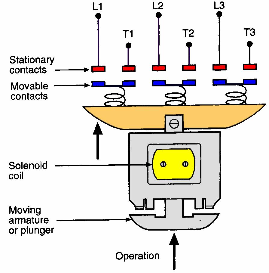
11 Magnetic Contactor

12 PLC Used In Conjunction With A Contactor Contactor power contacts Pump L2 L1 High-current wiring Low-current wiring L2 L1 Coil terminals Programmable controllers have I/O capable of operating the contactor but they do not have the capacity to operate heavy loads directly. PLC output module

13 Magnetic Motor Starter A magnetic motor starter is a contactor with an overload relay attached physically and electrically. They are electromagnetically operated switches that provide a safe method for starting large motor loads. The overload relay will open the supply voltage to the starter if it detects an overload on a motor. Motor overload relay contacts are normally hardwired in series with the magnetic starter coil.

14 Magnetic Motor Starter Overload heaters are connected in series with the contactor. If the motor becomes overloaded they cause a mechanical latch to trip. Tripping this latch opens a set of contacts that are wired in series with the voltage supply and motor.

15 Across-The-Line AC Starter Operation Low-current control circuit The When M the contacts, start button in series is with The OL pressed, the contact motor, coil M energizes close opens to complete automatically the high-current when an to close all M contacts. path overload to the condition motor. is sensed, to de-energize Control the M coil contact and stop M also the closes motor. to seal-in the coil circuit when the START button is released. High-current power circuit


16 PLC Control Of A Large Motor Load When a PLC needs to control a large motor, it must work in conjunction with a starter. Motor starters are available in various standard National Electric Manufacturers (NEMA) sizes and ratings.


17 Manually Operated Switches Manually operated switches are controlled by hand. Pushbutton switches are the most common form of manual control found in industry. Normally Open (NO) pushbutton makes a circuit when it is pressed and returns to its open position when the button is released.
18 Manually Operated Switches Normally Closed (NC) pushbutton opens the circuit when it is pressed and returns to the closed position when the button is released. The abbreviations NO and NC represent the state of the switch when it is not actuated.

19 Manually Operated Switches The break-make pushbutton is used for interlocking controls. In this switch the top section is NC, while the bottom section is NO. When the button is pressed, the bottom contacts are closed as the top contacts open. NOT PRESSED L1 ON R G OFF L2 L1 PRESSED OFF R G ON L2


20 Selector Switch Selector switch positions are made by turning the operator knob not pushing it. Hand Off Auto A B Contacts Position A B Hand X Off Auto X Selector switch positions may have two or more selector positions with either maintained contact position or spring return to give momentary contact operation.

21 Selector Switch Motor Reversing Selector switch used in conjunction with a reversing motor starter to select forward or reverse operation of the motor.

22 Dual In-Line Package (DIP) Switches ON OFF Are small switch assemblies designed for mounting on printed circuit board modules. Switch settings are seldom changed, and the changes occur mainly during installation or configuration of the system.

23 Mechanically Operated Switches A mechanically operated switch is controlled automatically by factors such as pressure, position, and temperature. The limit switch is a type of mechanically operated switch designed to operate only when a predetermined limit is reached, and is usually actuated by contact with an object such as a cam.

24 Limit Switch Operation Limit switches take the place of a human operator. Symbols NO Contact NC Contact They are often used in the control of machine processes to govern the starting, stopping, or reversal of motors.
25 Typical Limit Switch Circuit L1 Stop Forward FWD Limit L2 F Reverse R Limit switches F R OLs F REV Limit R Control circuit for starting and stopping a motor in forward and reverse with limit switches providing over travel protection.
26 Temperature Switch The temperature switch or thermostat is used to sense temperature changes and is actuated by some specific environmental temperature change. Responds to changes in temperature by opening or closing an electric circuit. Symbols NO Contact NC Contact


27 Temperature Switch Control of a Motor Closing ON Rising temperature Motor


28 Pressure Switch Pressure switches are used to control the pressure of liquids and gases and are activated when a specific pressure is reached. Opens or closes an electric circuit in response to a change in pressure. Bellows Switch Symbols NO Contact NC Contact


29 Starter Operated By A Pressure Switch Closing ON Rising pressure
30 Level Switch Level or float switches are used to sense the height of a liquid. Opens or closes an electric circuit in response to a change in liquid level. Switch Symbols Float NO Contact NC Contact Two-wire level switch control of starter.
Electrical Control System Components Basics of Magnetic Control :
 Electrical Control System Components Basics of Magnetic Control : Dr.M.S.Narkhede, LEE, GP Mumbai 1 Contact Types : Contacts are classified into different ways as follows. According to applications contacts
ECET 211 Electric Machines & Controls Lecture 4-1 Motor Control Devices: Lecture 4 Motor Control Devices
 ECET 211 Electric Machines & Controls Lecture 4-1 Motor Control Devices: Part 1. Manually Operated Switch Part 2. Mechanically Operated Switch Text Book: Electric Motors and Control Systems, by Frank D.
Module 2 CONTROL SYSTEM COMPONENTS. Lecture - 4 RELAYS
 1 Module 2 CONTROL SYSTEM COMPONENTS Lecture - 4 RELAYS Shameer A Koya Introduction Relays are generally used to accept information from some form of sensing device and convert it into proper power level,
Ch 4 Motor Control Devices
 Ch 4 Motor Control Devices Part 1 Manually Operated Switches 1. List three examples of primary motor control devices. (P 66) Answer: Motor contactor, starter, and controller or anything that control the
Basics of Control Components
 Basics of Control Components Table of Contents Introduction...2 Electrical Symbols...6 Line Diagrams...16 Overload Protection...22 Overload Relays...26 Manual Control...35 Magnetic Contactors and Starters...41
MOTOR TERMINAL CONNECTIONS
 MOTOR TERMINAL CONNECTIONS Motor Classification Most of the industrial machines in use today are driven by electric motors Motors are classified according to the type of power used (AC or DC) and the motors
Electrical Motor Controls Chapter 4 (Fourth Edition) Chapter 2 (Fifth Edition)
 Chapter 2 (Fifth Edition)") Electrical Motor Controls Chapter 4 (Fourth Edition) Chapter 2 (Fifth Edition) 1. Which drawing type shows physical details as seen by the eye? 2. Which drawing is similar to a pictorial drawing but has
Electrical Motor Controls Chapter 4 (Fourth Edition) Chapter 2 (Fifth Edition) 1. Which drawing type shows physical details as seen by the eye? 2. Which drawing is similar to a pictorial drawing but has
Chapter 8. Understanding the rules detailed in the National Electrical Code is critical to the proper installation of motor control circuits.
 Chapter 8 Understanding the rules detailed in the National Electrical Code is critical to the proper installation of motor control circuits. Article 430 of the NEC covers application and installation of
MOTOR TERMINAL CONNECTIONS
 MOTOR TERMINAL CONNECTIONS Motor Classification Most of the industrial machines in use today are driven by electric motors Motors are classified according to the type of power used (AC or DC) and the motors
MAGNETIC MOTOR STARTERS
 Chapter 6 MAGNETIC MOTOR STARTERS 1 The basic use for the magnetic contactor is for switching power in resistance heating elements, lighting, magnetic brakes, or heavy industrial solenoids. Contactors
The Contactor. Antonino Daviu, Jose Alfonso Departamento de Ingeniería Eléctrica. Universitat Politècnica de València
 The Contactor Surnames, name Antonino Daviu, Jose Alfonso (joanda@die.upv.es) Department Centre Departamento de Ingeniería Eléctrica Universitat Politècnica de València 1 1 Summary The aim of this paper
Electrical Motor Controls (Fourth Edition)
") Electrical Motor Controls (Fourth Edition) 1. Which drawing type shows physical details as seen by the eye? Pictorial Drawing 2. Which drawing is similar to a pictorial drawing but has circles or rectangles
Electrical Motor Controls (Fourth Edition) 1. Which drawing type shows physical details as seen by the eye? Pictorial Drawing 2. Which drawing is similar to a pictorial drawing but has circles or rectangles
Direct On Line (DOL) Motor Starter. Direct Online Motor Starter
 Motor Starter. Direct Online Motor Starter") Direct On Line (DOL) Motor Starter Direct Online Motor Starter Different starting methods are employed for starting induction motors because Induction Motor draws more starting current during starting.
Direct On Line (DOL) Motor Starter Direct Online Motor Starter Different starting methods are employed for starting induction motors because Induction Motor draws more starting current during starting.
MOTOR CONTROLLERS. STATE the function of motor controllers.
 Electrical Distribution Systems Motor controllers range from a simple toggle switch to a complex system using solenoids, relays, and timers. The basic functions of a motor controller are to control and
Push buttons are of two types i) Momentary push button ii) Maintained contact or detent push button
 Momentary push button ii) Maintained contact or detent push button") ELECTRO-PNEUMATIC Push button switches A push button is a switch used to close or open an electric control circuit. They are primarily used for starting and stopping of operation of machinery. This causes
ELECTRO-PNEUMATIC Push button switches A push button is a switch used to close or open an electric control circuit. They are primarily used for starting and stopping of operation of machinery. This causes
Types of Motor Starters There are several types of motor starters. However, the two most basic types of these electrical devices are:
 Introduction Motor starters are one of the major inventions for motor control applications. As the name suggests, a starter is an electrical device which controls the electrical power for starting a motor.
ECET 211 Electric Machines & Controls Lecture 6 Contactors and Motor Starters. Lecture 6 Contactors and Motor Starters
 ECET 211 Electric Machines & Controls Lecture 6 Contactors and Motor Starters Text Book: Chapter 6, Electric Motors and Control Systems, by Frank D. Petruzella, published by McGraw Hill, 2015. Paul I-Hai
1-3 MANUAL STARTERS EXERCISE OBJECTIVE. Examine and describe the operation of manual motor starters. DISCUSSION
 1-3 MANUAL STARTERS EXERCISE OBJECTIVE Examine and describe the operation of manual motor starters. DISCUSSION Motor starters are made out of power switches and overload protection devices. They can be
lectronic starter for single phase duction motor
 lectronic starter for single phase duction motor PROJECT NO: 104 SUPERVISOR: DR. WEKESA EXAMINER: PROF MANG OLI Prepared by: GITONGA HILDA WANJIKU- F17/39921/2011 PROJECT OUTLINE 1. Project Objective 2.
SPECIFICATIONS NB SKILLS TRADE 19 AUTOMATION AND CONTROL
 SPECIFICATIONS NB SKILLS TRADE 19 AUTOMATION AND CONTROL NBCC/CCNB 2016 1.1 SCENARIO. 3 1..1 GENERAL.. 3 1..2 STEP A: WIRING AN AUTOMATED PROCESS WITHIN A PANEL 3 1..3 STEP B: PROGRAMMING THE AUTOMATED
Controls and Instruments
 CHAPTER 9 Controls and Instruments A complex set of controls and instruments monitors the operation of an electric generator set. Equipment operators must understand what these controls and instruments
AF series contactors (9 2650)
") R E32527 R E39322 contactors General purpose and motor applications AF series contactors (9 2650) 3- & 4-pole contactors General purpose up to 2700 A Motor applications up to 50 hp, 900 kw NEMA Sizes 00
R E32527 R E39322 contactors General purpose and motor applications AF series contactors (9 2650) 3- & 4-pole contactors General purpose up to 2700 A Motor applications up to 50 hp, 900 kw NEMA Sizes 00
Electric Motor Controls BOMA Pre-Quiz
 Electric Motor Controls BOMA Pre-Quiz Name: 1. How does a U.P.S. (uninterruptable power supply) work? A. AC rectified to DC batteries then inverted to AC B. Batteries generate DC power C. Generator, batteries,
AC Rectifiers for use with Armature Actuated Brakes. Product Overview. Full Wave. Half Wave. Combination Full and Half Wave. TOR-AC Full and Half Wave
 Rectifiers for use with Armature Actuated Brakes Product Overview NOTE: For brake response times with and without rectifiers see page 94. Full Wave A rectifier in which both positive and negative half-cycles
R-MAG. Vacuum Circuit Breaker with Magnetic Actuator Mechanism
 R-MAG Vacuum Circuit Breaker with Magnetic Actuator Mechanism R-MAG Features: Low maintenance 10,000 mechanical operations (five times ANSI requirements) Simple magnetic actuator Vacuum interruption Definite
[You may download this article at: https://fluidsys.org/downloads/ ]
![[You may download this article at: https://fluidsys.org/downloads/ ]](/thumbs/75/72588514.jpg "[You may download this article at: https://fluidsys.org/downloads/ ]") Fluidsys Training Centre, Bangalore offers an extensive range of skill-based and industry-relevant courses in the field of Pneumatics and Hydraulics. For more details, please visit the website: https://fluidsys.org
Fluidsys Training Centre, Bangalore offers an extensive range of skill-based and industry-relevant courses in the field of Pneumatics and Hydraulics. For more details, please visit the website: https://fluidsys.org
AF series contactors (9 2650)
") R E32527 R E39322 contactors General purpose and motor applications AF series contactors (9 2650) 3- & 4-pole contactors General purpose up to 2700 A Motor applications up to 50 hp, 900 kw NEMA Sizes 00
R E32527 R E39322 contactors General purpose and motor applications AF series contactors (9 2650) 3- & 4-pole contactors General purpose up to 2700 A Motor applications up to 50 hp, 900 kw NEMA Sizes 00
Ktec Contactors and thermal overloads
 Contactors and thermal overloads Techna KTEC series contactors provide a complete solution for your ac contactor requirements.the range carries TUV, UL & CSA certification, for use in Europe, North America
Electro - Hydraulics. & Pneumatics. Electro Hydraulic Press. Comparison. Electro Hydraulics. By: Alireza Safikhani
 Electro - 9 Hydraulics & Pneumatics 2 Electro Hydraulic Press The hydraulic press is controlled via the electrical control panel. Electrical signals are used to activate the valves in the hydraulic installation.
THE BEST ELECTRICAL CONTROLS BUSINESS ON THE PLANET! Unmatched Service Superior Product Quality Advantage Pricing
 Introduction A contactor is an electrical device which is used for switching an electrical circuit on or off. It is considered to be a special type of relay. However, the basic difference between the relay
Horizontal Circuit Switchers
 > Transformer Protection > CIRCUIT SWITCHERS C A T A L O G B U L L E T I N General Application Southern States Types CSH and CSH-B Horizontal Circuit Switchers provide an economical, versatile, space saving
SECTION MOTOR CONTROL
 SECTION 26 24 19 MOTOR CONTROL PART 1 - GENERAL 1.1 SECTION INCLUDES A. Manual motor starters B. Magnetic motor starters C. Combination magnetic motor starters D. Solid-state reduced voltage motor starters
Horizontal Circuit Switchers
 > Transformer Protection > CIRCUIT SWITCHERS C A T A L O G B U L L E T I N General Application Southern States Types CSH and CSH-B Horizontal Circuit Switchers provide an economical, versatile, space saving
Process switches and PLC circuits
 Process switches and PLC circuits This worksheet and all related files are licensed under the Creative Commons Attribution License, version 1.0. To view a copy of this license, visit http://creativecommons.org/licenses/by/1.0/,
XCITE Owner s Manual. Reso-not TM Damping System XCITE 1502C HYDRAULIC POWER SUPPLY
 Reso-not TM Damping System XCITE Owner s Manual 1502C HYDRAULIC POWER SUPPLY Xcite Systems Corporation 675 Cincinnati RDS Batavia - 1 Pike Cincinnati, Ohio 45245 Tel: (239) 980-9093 Fax: (239) 985-0074
Aldi V4 & V V1.1 5/23/2014
 Aldi V4 & V5 2012 2013 V1.1 5/23/2014 Aldi Control Techniques SK Series VFD & Hussmann MX Series MicroChannel Condenser Equipment Operation Component Orientation Control Wiring Programming and Start Up
Exercise 1-5. Current Protection Devices EXERCISE OBJECTIVE DISCUSSION OUTLINE DISCUSSION. Circuit breakers
 Exercise 1-5 Current Protection Devices EXERCISE OBJECTIVE Describe and test the operation of circuit breakers, fuses, and overload relays. DISCUSSION OUTLINE The Discussion of this exercise covers the
AF09... AF38 3-pole contactors 4 to 18.5 kw, AC / DC operated
 AF09... AF3 3-pole contactors 4 to 1.5 kw, AC / DC operated AF09-30-10 AF09... AF3 contactors are mainly used for controlling 3-phase motors and power circuits up to 690 V AC and 220 V DC. These contactors
Open & enclosed. Spec Tech Industrial 203 Vest Ave. Valley Park, MO Phone: 888 SPECTECH. Reduced voltage starters. Overload relay protection
 Reduced voltage starters Open & enclosed Reduced voltage starters Description Compact, space saving design 8 starter frame sizes, A16 to A750 Maximum U.L. horsepower ratings Mechanically interlocking as
R-MAG Vacuum Circuit Breaker with Magnetic Actuator Mechanism 15.5 kv - 27 kv; 1200 A A
 R-MAG Vacuum Circuit Breaker with Magnetic Actuator Mechanism 15.5 kv - 27 kv; 1200 A - 3700 A R-MAG The R-MAG is truly the next generation in vacuum circuit breakers, combining industry recognized magnetic
Tattletale Annunciators and Magnetic Switches
 Tattletale Annunciators and Magnetic Switches Tattletale annunciators and magnetic switches are the nerve centers that translate Swichgage contact operations into decisions and operate the alarm or shutdown
Starting of Induction Motors
 1- Star Delta Starter The method achieved low starting current by first connecting the stator winding in star configuration, and then after the motor reaches a certain speed, throw switch changes the winding
PATTERSON PUMP COMPANY
 PATTERSON PUMP COMPANY A Gorman Rupp Company JOCKEY PUMP CONTROLLERS UL508 LISTED ETL LISTED FEB 013 Patterson Jockey Pump controllers are built to NEMA industrial standards and are UL508 listed and ETL
9/7/2010. Chapter , The McGraw-Hill Companies, Inc. MOTOR CLASSIFICATION. 2010, The McGraw-Hill Companies, Inc.
 Chapter 2 MOTOR CLASSIFICATION 1 In general, motors are classified according to the type of power used (AC or DC) and the motor's principle of operation. AC DC Motor Family Tree 2 DC MOTOR CONNECTIONS
AUTOMATION AND CONTROL TRADE 19 TAR SANDS
 AUTOMATION AND CONTROL TRADE 19 TAR SANDS Page 1 1.1.1 - General With this challenge, we will assess your: a) ability to analyze technical data. b) quality of wiring. c) capacity to implement an automatic
CI-TI Contactors and motor starters Types CI 61 - CI 98
 Data sheet CI-TI Contactors and motor starters s CI 6 - CI 98 Contactors CI 6, CI 7, CI 86 and CI 98 switch powers of up to 0 kw, 7 kw, 45 kw and 55 kw respectively under 80 V - loads. Accessories include
Motor-drive mechanism, type BUL. Technical guide
 Motor-drive mechanism, type BUL Technical guide This Technical Guide has been produced to allow transformer manufacturers, and their designers and engineers, access to all the technical information required
PREVIEW ONLY - FULL COPY AVAILABLE TO CONSORTIUM MEMBERS. Escalator Specific Electrical Systems. Course 209 PARTICIPANT GUIDE
 Escalator Specific Electrical Systems Course 209 PARTICIPANT GUIDE Transit Elevator/Escalator Training Consortium Escalator: Electrical Systems Participant Guide Transit Elevator/Escalator Maintenance
Exercise 1-3. Manual Starters EXERCISE OBJECTIVE DISCUSSION OUTLINE DISCUSSION. Direct-on-line (DOL) starters. Reversing starters
 starters. Reversing starters") Exercise 1-3 Manual Starters EXERCISE OBJECTIVE Examine and describe the operation of manual motor starters. DISCUSSION OUTLINE The Discussion of this exercise covers the following points: Direct-on-line
Exercise 1-3 Manual Starters EXERCISE OBJECTIVE Examine and describe the operation of manual motor starters. DISCUSSION OUTLINE The Discussion of this exercise covers the following points: Direct-on-line
Industrial Automation Commonly-Used Terms
 Industrial Automation Commonly-Used Terms A Glossary of Industrial Automation and Control Terms LECINC.COM 1 A Accelerating Time: Across the Line Starter: Action Device: Actuator: Air (used as prefix):
IEC Utilization Categories (Explanation)
") IEC Utilization Categories (Explanation) IEC Utilization Categories Voltage Category Typical Applications A.C. A.C. and D.C. D.C. AC AC AC AC ACa ACb AC6a AC6b AC7a AC7b AC8a AC8b AC AC AC AC AC AC AC
IEC Utilization Categories (Explanation) IEC Utilization Categories Voltage Category Typical Applications A.C. A.C. and D.C. D.C. AC AC AC AC ACa ACb AC6a AC6b AC7a AC7b AC8a AC8b AC AC AC AC AC AC AC
MANUAL ELECTRIC FIRE PUMP CONTROLLERS METRON SERIES M450
 MANUAL ELECTRIC FIRE PUMP CONTROLLERS METRON SERIES M450 TABLE OF CONTENTS PART I GENERAL DESCRIPTION... PAGE 2 PART II FUNCTIONS... PAGE 2 PART III INSTALLATION... PAGE 3 PART IV INITIAL INSTALLATION
AQUASTAR C6. (Comfort 6000) Next Generation Auto Backwash Valve System. (selectable time-pressure or remote cycle start)
 Next Generation Auto Backwash Valve System. (selectable time-pressure or remote cycle start)") AQUASTAR C6 (Comfort 6000) Next Generation Auto Backwash Valve System (selectable time-pressure or remote cycle start) SIDE MOUNTED AND TOP MOUNTED VALVES WITH QUICK INSTALL ELECTRIC ACTUATORS FOR PIPE
AQUASTAR C6 (Comfort 6000) Next Generation Auto Backwash Valve System (selectable time-pressure or remote cycle start) SIDE MOUNTED AND TOP MOUNTED VALVES WITH QUICK INSTALL ELECTRIC ACTUATORS FOR PIPE
Packaged Design Day Tank Systems
 Fuel Supply Systems Packaged Design Day Tank Systems for diesel/fuel oil application providing a reliable fuel source for diesel and turbine engine driven equipment and oil fired boilers model & accessory
Air-insulated switchgear UniGear type ZS1
 Air-insulated switchgear UniGear type ZS1 ABB Power Technologies / 1-7074 D 12-03-2003 - Air-insulated switchgear UniGear type ZS1 ABB Power Technologies / 2-7075 D 1 2-03-2003 - Rated voltage kv 12 17.5
FIRE DOOR OPERATOR WARNING INSTALLATION LOGIC BOARD REPLACEMENT KIT K , K A-400 & K B-400 APPLICATION REMOVE AC AND DC POWER
 APPLICATION Replacement of logic board for Models FDO and FDC operators with Rev. 400 wiring. FIRE DOOR OPERATOR LOGIC BOARD REPLACEMENT KIT K79-3493-400, K79-3493A-400 & K79-3493B-400 WARNING To prevent
3TM Vacuum Contactors
 Catalog Extract HG 11.23 Edition 2016 Catalog Extract Medium-Voltage Equipment siemens.com/3tm R-HG11-343.psd 2 Siemens HG 11.23 2016 Contents Medium-Voltage Equipment Catalog Extract HG 11.23 2016 Contents
AF40... AF96 3-pole contactors 30 to 60 hp at 480 V AC AC / DC operated with 1 N.O. + 1 N.C. auxiliary contacts
 AF4... AF96 -pole contactors to 6 hp at 48 V AC AC / DC operated with N.O. N.C. auxiliary contacts Description AF4... AF96 contactors are mainly used for controlling -phase motors and power circuits up
A200 NEMA Contactors and Starters A200
 Starters Non-reversing and Reversing 11 Not to be used for construction purposes unless approved. Table 11. Open Reversing Starters Dimensions NEM of Poles Fig. Mounting Dimensions in Inches (mm) Screws
MANUAL ELECTRIC FIRE PUMP CONTROLLERS METRON SERIES MV600
 MANUAL ELECTRIC FIRE PUMP CONTROLLERS METRON SERIES MV600 TABLE OF CONTENTS PART I GENERAL DESCRIPTION... PAGE 2 PART II FUNCTIONS... PAGE 2 PART III INSTALLATION... PAGE 3 PART IV INITIAL INSTALLATION
Small Motor Control (1/4 HP HP)
") PDHonline Course E110 (2 PDH) Small Motor Control (1/4 HP - 200 HP) Instructor: Thomas Mason, P.E. 2012 PDH Online PDH Center 5272 Meadow Estates Drive Fairfax, VA 22030-6658 Phone & Fax: 703-988-0088
PDHonline Course E110 (2 PDH) Small Motor Control (1/4 HP - 200 HP) Instructor: Thomas Mason, P.E. 2012 PDH Online PDH Center 5272 Meadow Estates Drive Fairfax, VA 22030-6658 Phone & Fax: 703-988-0088
Time delay relays. The following is a timing diagram of this relay contact's operation:
 Time delay relays Some relays are constructed with a kind of "shock absorber" mechanism attached to the armature which prevents immediate, full motion when the coil is either energized or de-energized.
AF40... AF96 3-pole contactors Technical data
 Main pole - Utilization characteristics according to IEC Standards IEC 60947- / 60947-4- and EN 60947- / 60947-4- Rated operational voltage Ue max. 690 V Rated frequency (without derating) 50 / 60 Hz Conventional
NEMA Full Voltage Power Devices. Section 1. Control Catalog 1-1
 NEMA Rated Full Voltage Power Devices Application Information and Technical Data (300-Line)...-4 Magnetic Nonreversing Starters (CR306, CR386) Basic Features (300-Line) and Technical Features (CR306, CR386)...-7
Exercise 4-1. Friction Brakes EXERCISE OBJECTIVE DISCUSSION. Understand the construction and operation of friction brakes.
 Exercise 4-1 Friction Brakes EXERCISE OBJECTIVE Understand the construction and operation of friction brakes. DISCUSSION Friction brakes, or magnetic brakes, are used to secure (hold) the position of a
Adapted from presentation developed by Scott Fausneaucht
 Adapted from presentation developed by Scott Fausneaucht Definition of Electricity Electrical Fundamentals Generation & Transmission Transformers Fuses & Circuit Breakers Motors Motor Controls Safety Not
SafeGear TM Motor Control Center Arc resistant metal-clad construction
 SafeGear TM Motor Control Center Arc resistant metal-clad construction Contents Description 2 SafeGear TM MCC applications 3 Electrical features 3 Standards 3 Standard service conditions 4 HCV vacuum contactor
Contactors & Starters Index
 ontactors & Starters Index NEMA ontrol Description Page Number General Information - HP... A Magnetic ontactors - HP...4 A Magnetic Reversing ontactors - HP... 4 A Magnetic Starters - HP... A Magnetic
* With I-Option card only (C. T. connection) Basic connections with isolated contacts
 Basic connections with isolated contacts") Typical Circuit Diagrams. Typical Circuit Diagrams Basic connections with isolated contacts F2 - Overload relay Q1 - MPCB / ACB / MCCB /K2 - Main isolating contactors (AC-3 rated) F3 - Semiconductor Fuses
Typical Circuit Diagrams. Typical Circuit Diagrams Basic connections with isolated contacts F2 - Overload relay Q1 - MPCB / ACB / MCCB /K2 - Main isolating contactors (AC-3 rated) F3 - Semiconductor Fuses
Fincor Series 2230 MKII/2240
 Fincor Series 2230 MKII/ Fincor Series 2200 regenerative drives are ideal for your more demanding applications. They feature flexibility with ratings up to 5 horsepower. The Series 2230 MKII offers new
AF / AF12Z pole Contactors AC / DC Operated - with Screw Terminals
 Technical Datasheet 1SBC101404D0201 24/03/11-30-10-.. / Z-30-10-.. 3-pole Contactors AC / DC Operated - with Screw Terminals (Z) contactors are used for controlling power circuits up to 690 V AC and 220
Operation and Maintenance Manual
 OM-2075 430577-31 011596 Operation and Maintenance Manual Model 90C24 Generator Set Part No. 500046 Hobart Brothers Company Airport Systems Group Ground Power Equipment Troy, OH 45373 U.S.A. This page
Government Polytechnic Muzaffarpur Name of the Lab: Electric Traction-II Lab
 Government Polytechnic Muzaffarpur Name of the Lab: Electric Traction-II Lab Subject Code: 1620609A Experiment-1 Aim: Study of various traction systems. Theory: A traction system is of mainly two type
Electric control panel
 Overview This electric control panel is used for UE and U type motor driven grease pump. It enables comfortable use of centralized lubricating system, and also plays a role in saving labor in a plant because
Overview. Contents. Overview
 1/0 Overview 1 Contents Overview 3-pole Block Contactors and Motor Protection... 1/ 4-pole Block Contactors... 1/3 Contactors for Specific Applications... 1/4 Mini Contactors and Motor Protection... 1/
Automation is the techniques and equipment used to achieve automatic operation or control.
 VALVE AUTOMATION What is Automation? Automation is the techniques and equipment used to achieve automatic operation or control. Automation is an automatic operation and control of machinery or processes
TYPE KF UNDER-FREQUENCY RELAY A. Figure 1: Type KF Relay for 60 Hertz without Case. (Front & Rear View.) Front View Rear View
 Front View Rear View") 41-503.21A TYPE KF Front View Rear View Figure 1: Type KF Relay for 60 Hertz without Case. (Front & Rear View.) 2 TYPE KF 41-503.21A lower pin bearing, which is mounted on the frame, with respect to the
41-503.21A TYPE KF Front View Rear View Figure 1: Type KF Relay for 60 Hertz without Case. (Front & Rear View.) 2 TYPE KF 41-503.21A lower pin bearing, which is mounted on the frame, with respect to the
Series A Construction
 Page 1 of 7 Knowledgebase Technote ID # Q18363 9/2/2003 505 Series A Construction 505 505 1495-F1 (1 N.O. auxiliary contact) 1495-G5 (1 N.C. early break auxiliary contact) 1495-H0 ( 1 N.C. late break auxiliary
Contactor Types CI 61-98
 MKING MODERN LIVING POSSIBLE Data sheet Contactor s CI 6-98 Contactors CI 6, CI 73, CI 86 and CI 98 switch powers of up to 30 kw, 37 kw, 45 kw and 55 kw respectively under 3 380 V C-3 loads. ccessories
Type SDV7 distribution circuit breaker family
 www.usa.siemens.com/sdv7 Type SDV7 distribution circuit breaker family 5.5 kv to 8.0 kv Answers for infrastructure. Table of contents Introduction 0 Vacuum interrupters 0 Simple current path 05 Low-maintenance
Induction Power Supplies
 Induction Power Supplies 7.5kW; 135 400kHz 480V version (Integral Heat Station) User s Guide Model 7.5-135/400-3-480 SMD Control Brds Rev. D 5/08 Table of Contents 1. Specifications and features...3 2.
Heavy-Duty Safety Interlock Switch with Guard Door Locking
 C R US Conforms to EN1088, EN60947--1, EN292, EN60204-1 UL and C-UL listed TL8018- Heavy-Duty Safety Interlock Switch with uard Door Locking High locking force of,00 N (1,236 lb.) locks guard door shut
ECET 211 Electric Machines & Controls Lecture 6 Contactors and Motor Starters (2 of 2) Lecture 6 Contactors and Motor Starters
 Lecture 6 Contactors and Motor Starters") ECET 211 Electric Machines & Controls Lecture 6 Contactors and Motor Starters (2 of 2) Text Book: Chapter 6, Electric Motors and Control Systems, by Frank D. Petruzella, published by McGraw Hill, 2015.
ECET 211 Electric Machines & Controls Lecture 6 Contactors and Motor Starters (2 of 2) Text Book: Chapter 6, Electric Motors and Control Systems, by Frank D. Petruzella, published by McGraw Hill, 2015.
AF / AF30Z stack 3-pole Contactors AC / DC Operated - with Screw Terminals
 Technical Datasheet 1SBC101415D0201 25/03/11 AF30-30-11-.. / AF30Z-30-11-.. 2-stack 3-pole Contactors AC / DC Operated - with Screw Terminals AF30(Z) contactors are used for controlling power circuits
MODEL 520 REMOTE START ENGINE MANAGEMENT SYSTEM
 MODEL 520 REMOTE START ENGINE MANAGEMENT SYSTEM DSE 520 ISSUE 4 4/4/02 MR 1 TABLE OF CONTENTS Section Page INTRODUCTION... 4 CLARIFICATION OF NOTATION USED WITHIN THIS PUBLICATION.... 4 1. OPERATION...
STEP Motor Control Centers
 STEP 2000 Motor Control Centers Table of Contents Introduction...2 Motor Control...4 Power Supplies...8 Design Standards...13 Need for Circuit Protection...14 Overcurrent-Protection Devices...19 Motor
DISCUSSION OF FUNDAMENTALS. A hydraulic system can be controlled either manually or automatically:
 Unit 1 Introduction to Electrical Control of Hydraulic Systems UNIT OBJECTIVE When you have completed this unit, you will be able to identify the components used for electrical control of the Hydraulics
KD LV Motor Protection Relay
 1. Protection Features KD LV Motor Protection Relay Overload (for both cyclic and sustained overload conditions) Locked rotor by vectorial stall Running stall / jam Single phasing / Unbalance Earth leakage
331-SV. User Manual THREE PHASE DUPLEX LIFT STATION CONTROL PANEL WITH STATIONVIEW CONTROLLER. Ashland, OH
 331-SV User Manual THREE PHASE DUPLEX LIFT STATION CONTROL PANEL WITH STATIONVIEW CONTROLLER Ashland, OH 800-363-5842 WWW.PRIMEXCONTROLS.COM Warranty void if panel is modified. Call factory with servicing
Exercise 5-1. Primary Resistor Starters EXERCISE OBJECTIVE DISCUSSION. Understand how primary resistor starters operate.
 Exercise 5-1 Primary Resistor Starters EXERCISE OBJECTIVE Understand how primary resistor starters operate. DISCUSSION High starting torque can result in sudden acceleration and damage to the driven machinery.
SafeGear Motor Control Center Arc Resistant Metal-Clad Construction Brochure
 2017 SafeGear Motor Control Center Arc Resistant Metal-Clad Construction Brochure SafeGear Motor Control Center Arc resistant Metal-Clad construction Brochure Table of Contents 1. Description 1 1 2. SafeGear
SECTION 2 - PROCEDURES. Features. 2.6 MOTOR CONTROLLER. Modes of Operation JLG Lift 2-5
 2.6 MOTOR CONTROLLER. Modes of Operation. 1. Traction Motor Drive. a. Drive in either forward or reverse will start only if the following conditions are satisfied: 1. Function switches off. 2. No procedure
32XR. 3 Phase Duplex Pump Control Panel (Level Transmitter Based) Quick Start Guide
 Quick Start Guide") 32XR 3 Phase Duplex Pump Control Panel (Level Transmitter Based) Quick Start Guide RED ALARM LIGHT LEVEL CONTROLLER H-O-A SWITCHES HORN SILENCE INNER DOOR MOTOR STARTERS WITH INTERCHANGEABLE OVERLOAD MODULES
32XR 3 Phase Duplex Pump Control Panel (Level Transmitter Based) Quick Start Guide RED ALARM LIGHT LEVEL CONTROLLER H-O-A SWITCHES HORN SILENCE INNER DOOR MOTOR STARTERS WITH INTERCHANGEABLE OVERLOAD MODULES
MAXIGARD A2000 SPEED SWITCH. Introduction
 A107-05, Page 1 952-361-3026, INC. (Fax) 952-368-4129 327 LAKE HAZELTINE DRIVE, CHASKA, MN 55318 800-328-0738 MAXIGARD A2000 SPEED SWITCH Introduction The Maxigard A2000 Speed Switch is designed to monitor
A5000GEC-24VDC ZERO SPEED SWITCH
 A208-05, Page 1 952-361-3026, INC. (Fax) 952-368-4129 327 LAKE HAZELTINE DRIVE, CHASKA, MN 55318 800-328-0738 A5000GEC-24VDC ZERO SPEED SWITCH Introduction The MAXIGARD A5000GEC-24VDC is a zero speed switch
Reliably Switching Highest Currents up to 2000 A
 www.moeller.net Reliably Switching Highest Currents up to 2000 A The complete range for the motor circuit. From contactors to efficient motor-starters to controlled drives. New solutions that rely on communication.
ELECTRICAL TECHNOLOGY 3 March 2008
 I. Course Description ELECTRICAL TECHNOLOGY 3 March 2008 The purpose for this course is to instruct potential electricians in the skills necessary for entry into the job market. During this course, the
PREVIEW COPY. Table of Contents. Lesson Two Switches and Controls Special Control Switches Lesson Six Control Relays...
 Table of Contents Lesson One Motor Starters...3 Lesson Two Switches and Controls...19 Lesson Three Limit Switches...37 Lesson Four Lesson Five Special Control Switches...55 Timers and Counters...71 Lesson
AC/DC ELECTRICAL SYSTEMS
 AC/DC ELECTRICAL SYSTEMS LEARNING ACTIVITY PACKET BASIC ELECTRICAL CIRCUITS BB227-BC01UEN LEARNING ACTIVITY PACKET 1 BASIC ELECTRICAL CIRCUITS INTRODUCTION Electricity is used to perform tasks related
Reliably Switching Highest Currents up to 2200 A
 www.moeller.net Reliably Switching Highest Currents up to 2200 A Product Information DIL M contactors DIL H contactors High Rated Contactors DIL: Switching High Currents Reliably Contactors DIL M from