Viento OPERATION MANUAL
|
|
|
- Milton Lambert
- 5 years ago
- Views:
Transcription


1 OPERATION MANUAL

2 FläktGroup Product Range T y p e n s c h l ü s s e l 2 FläktGroup DC GB /R4 Subject to modifications
3 Unit code Accessories L. A 1 U LZ A 1 Series: for door heights A = m* B = m* C = m* Model size: for door widths 1 = 1.0 m 2 = 1.5 m 3 = 2.0 m Design/operating mode U = Recirculating air M = Mixed air Heat exchanger 0 = Without heat exchanger 2 = 2-row (connection side on left)** 3 = 3-row (connection side on left)** 8 = 2-row (connection side on right)** 9 = 3-rows (connection side right)** Motor/electric equipment Motor with integrated thermal contacts 1 = Stage (for control units MC20 - MC30) G = Stage (for control units MCR 25) J = Stage X-Y-Z (speed by choice for control units MCR 25 or control on-site)*** Motor with exiting thermal contacts 2 = Stage (for control units MC20 - MC30) N = Stage (for control units MCR 25) T = Stage X-Y-Z (speed by choice for control units MCR 25 or control on-site)*** Accessories Supply-air side 10 = Discharge sheet steel branch piece with air deflection louvre Recirculating-air side 20 = Air intake bend 21 = Intake flexible connector 22 = Air-intake grille with sheet steel branch piece Outdoor-air side 30 = Intake duct (installation of mixing-air chamber) 31 = Intake duct (connection of accessory items ) 32 = External weather grille Suspension devices 40 = Ceiling mounting unit, galvanized 41 = Ceiling mounting unit, RAL = Wall mounting unit, galvanized 43 = Wall mounting unit, RAL = Connection piece for 2 units 60 = Spare filters (1 set with 5 pieces) Series and model size (refer to unit type code) Valves 0 = without installed valve, without piping 1 = without installed valve, only piping 2 = 2-way thermostat valve R3/4" (R 1" for C3 series) for supply-air temperature control Unit casing 0 = without casing 1 = with casing, color RAL = with casing, RAL color freely selectable (only RAL shades without aluminum components) * On request ** The standard heat exchanger connection is on the left (facing intake side for a horizontally mounted unit). Heat exchanger connection on the right (code numbers 8, 9) only on request, please contact our sales colleague or sales representative. *** The chosen speed stage combination must be mentioned in the order. FläktGroup DC GB /R4 Subject to modifications 3
4 1 Safety and User Instructions Scope of application of the operation manual Used symbols Safety-conscious work procedures Personnel selection and qualification Proper use Improper use Safety regulations and codes Modifications and changes Spare parts Personnel selection and qualification Technical Description Unit Components Material specification Functional principle of air curtains in recirculating-air mode Use of air curtains in mixed-air operation Assembly of the air curtains Operating limits Unit and heat exchanger Water charge of heat exchangers Integrated thermostatic valves (optional) Shut-off valves with thermoelectric actuator (optional accessories) Dimensional drawings and technical data Air curtains - series A - suspension height 2.5 m Air curtains - series B - suspension height 3.0 m Air curtains - series C - suspension height 3.5 m Accessory Shipping and storage Transport safety Scope of delivery Manipulation and shipping Shipping of air curtains without casing Shipping of air curtains with casing Temporary storage Transport FläktGroup DC GB /R4 Subject to modifications
5 4 Assembly Installation site Safety clearance Wall installation Ceiling installation Connect several units Units without air-side accessories Units with air-side accessories Hydraulic connection Shut-off valves (accessories optional) Passage form (optional accessories) Corner form (optional accessory) way valve (corner form) with thermostatic actuator (selectable) Electrical connection Requirements on-site Isolating device for supply line on-site Connection to mains network Speed change of air curtain Connecting air curtain Connect control units calculation examples Control unit MC 20E with air curtain Control unit MC 21-P1 with an air curtain Control unit MC 21-P2 with two air curtains Control unit MC 21-P3 with three air curtains Control unit MC 25-P1 with an air curtain Control unit MC 25-P2 with two air curtains Control unit MC 25-P3 with three air curtains Control unit MC 30-P1 with an air curtain Control unit MC 30-P2 with two air curtains Control unit MC 30-P3 with three air curtains Control units MCR Wiring diagrams control units with control by others Recirculating-air unit with control by others Mixed-air unit with control by others Commissioning Initial commissioning Air venting of heat exchangers Check the valves Operation of air curtain Operation with the control unit MC Operation of the air curtain using control unit MCR FläktGroup DC GB /R4 Subject to modifications 5
6 8 Maintenance Maintenance Clean every three months Replace filter Check before frost period Semi-annual maintenance Check the fan Check heat exchanger Check the screwed connection and valve connection Check electrical connections and earthing Enabling after fault Dismantling and Disposal Dismantling Recycling Original operation manual Copyright note Disclosing, copying, distributing or taking any action in reliance on the contents of this document is strictly prohibited without express prior consent. Violations entail liability for any damages or other liability arising. All rights in relation to patents, utility patents or design patents are reserved. 6 FläktGroup DC GB /R4 Subject to modifications
7 Safety and User Instructions 1 Safety and User Instructions This is an original operation manual verified by the manufacturer. air curtains are developed and manufactured according to the state-of-the-art technological standards, established technical safety codes and EC Directive on Machinery. air curtains ensure maximum operational safety and meet the highest quality standards. Future-oriented technology and pronounced operator and maintenance friendliness were combined in this product series. However, every air curtain unit can pose an unavoidable residual risk of injury or risk of equipment or other property. Therefore your personal safety and the proper operation of the unit depend on the strict observance of the safety instructions. Failure to follow the safety precautions could result in death, serious injury, environmental damage and/or considerable property damage. Observing the safety instructions in the current operation manual will help avoid the risks, ensure economical operation of the unit and let you enjoy the full benefits of the product. The safety aspects covered by this chapter are valid for the entire operation manual. 1.1 Scope of application of the operation manual This operation manual provides information about the following: Transport Assembly Installation Electrical installation Commissioning Operation Maintenance, cleaning and disposal 1.2 Used symbols The following symbols are used to highlight particular text sections in this operation manual: This symbol is used to indicate lists. This symbol indicates handling instructions. This symbol indicates the result of an action. User instructions User instructions provide optimal, efficient and environmentally friendly methods for using and handling the units. The following warnings are used: Danger of electrical current! This symbol indicates a risk of electrical shock that can result in serious injury, death and material damage. PERSONAL injury! This symbol indicates (in contrast to the above-mentioned danger types) a hazardous location with a risk of personal injury including death and material damage. Danger due to overhead loads! This symbol indicates a hazardous location with a risk of personal injury including death and material damage. FläktGroup DC GB /R4 Subject to modifications 7
8 Safety and User Instructions Risk of accident due to hot medium! This section specifies procedures and precautions for preventing personal injury resulting from contact with a hot medium. Danger of sharp cutting edges! This section specifies procedures and precautions for preventing personal injury resulting from cuts caused by sheet metal. Caution due to rotating components! This symbol indicates a hazardous location with a risk of personal injury including death and material damage. Environmental damage! This symbol warns about possible damage to the environment. Danger of scalding! This symbol indicates a risk of scalding from leaking hot liquids that can result in personal injury, including death and material damage. Damage to the unit! This symbol indicates a hazardous location with a risk of material damage that can also lead to personal injury. 1.3 Safety-conscious work procedures To ensure your own safety, comply with the following safety instructions: Hazardous voltage! Before carrying out any jobs on the unit, power the unit down to prevent injury from electrical current. Ensure that the unit is secured against being energized again at an appropriate point of the on-site power supply. Caution due to rotating components! Rotating fan impeller wheel poses a risk of injury! Before performing any work on the unit, ensure that the unit is disconnected and powered down. Ensure that the unit is insulated and secured against being switched on at an appropriate point of the on-site power supply. Fluctuations or deviations of the supply voltage may not exceed the tolerance limits specified in the technical data on the unit identification plate, otherwise function failures and limit states cannot be excluded. 1.4 Personnel selection and qualification The unit may be installed, operated and maintained only by qualified, specially trained and authorized staff. The following tasks described in the operation manual may only be performed by qualified personnel: Shipping and storage Assembly Hydraulic connection Electrical connection Commissioning Maintenance 8 FläktGroup DC GB /R4 Subject to modifications
9 Safety and User Instructions 1.5 Proper use Units must be operated in accordance with EU 1253/2014. air curtains are mainly used in warehouses, sales and exhibition buildings, i.e. in normal ambient conditions according to the EN and are exclusively designed for ventilating, air heating or filtrating fresh and indoor air. Water or water/glycol solution (max. 50 %) may be used as medium. Proper use also stipulates the observance of the operation manual as well as adherence to all inspection and maintenance intervals specified by FläktGroup. Damage to the unit! During installation, the air curtain must be placed in such a way to prevent any condensation or splash water penetrating into the electric equipment and causing damage to the unit. The following limit values apply to the medium for operating Cu/Al heat exchangers: Parameter Unit Value ph value (at 20 C) Conductivity (at 20 C) μs/cm < 700 Oxygen content O 2 mg/l < 0.1 Total hardness dh 1-15 Dissolved sulfur S not detectable Sodium Na + mg/l < 100 Iron Fe 2+, Fe 3+ mg/l < 0.1 Manganese Mn 2+ mg/l < 0.05 Ammonium content + NH 4 mg/l < 0.1 Chloride Cl - mg/l < 100 Sulfate 2- SO 4 mg/l < 50 Nitrite NO - 2 mg/l < 50 Nitrate - NO 3 mg/l < 50 Tab. 1-1: Limit values for medium used in closed heating and cooling circuits Damage to the unit! In open systems (e.g. when using well water be sure to observe the limit values from table Tab. 1-1), the water used should additionally be cleansed of suspended matter using a filter to be installed at the inlet. Failure to do so could result in the risk of erosion by suspended matter. Also ensure that the unit is protected from dust and other substances that can cause acidic or alkaline reactions with water (aluminum corrosion). 1.6 Improper use The unit is considered to be used in an improper manner if it is applied for other purposes or a purpose that is not covered by the previous chapter. The manufacturer or supplier is not liable for any resulting damage; the user alone bears the full risk. The may not be operated: outdoors, in areas with explosion risk, in wet areas, in rooms with strong electromagnetic fields or in locations with high dust levels or aggressive air. Personal injury and equipment damage! Improper use can cause personal injury and material damage. FläktGroup DC GB /R4 Subject to modifications 9
10 Safety and User Instructions 1.7 Safety regulations and codes 1.8 Modifications and changes When carrying out installation, commissioning, maintenance and service of the air curtains, observe all local safety regulations and codes as well as generally established technical practices. No changes, add-ons or modifications may be performed on the air curtains or their components. Changes or modifications of the unit will invalidate the CE conformity and render all warranty claims null and void. 1.9 Spare parts You may use only original FläktGroup spare parts, since FläktGroup is not liable if any third party spare components are used Personnel selection and qualification Ensure that every person working on the air curtains has read and understood the entire operation manual. It is too late to do this after the work has already begun. Electrical and water connections must be established by qualified licensed staff or other individuals with proper professional training and experience in the following areas: Regulations concerning health and safety in the workplace Accident prevention regulations Guidelines and recognized codes for technical practice and engineering All tradespeople must be able to assess the work assigned to them, and recognize and avoid all associated dangers. 10 FläktGroup DC GB /R4 Subject to modifications

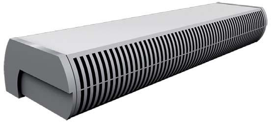
11 Technical Description 2 Technical Description 2.1 Unit Components Fig. 2-1: Unit Components Pos. 1: External weather grille LZ.32.## Pos. 2: Intake duct LZ.31.## Pos. 3: Intake duct LZ.30. ## Pos. 4: Mixing section: for mixed-air units no accessories, included in basic unit Pos. 5: Air-intake bend LZ.20.##: for recirculating-air units with dimension as mixing section, but without mixing damper Pos. 6: Intake flexible canvas connector LZ.21.## Pos. 7: Air-intake grille with sheet steel branch piece LZ.22.## Pos. 8: Connection sheet - for connecting two air curtains (supplied as standard) Pos. 9: Discharge sheet steel branch piece with air deflection louvre LZ.10.## Pos. 10: air curtain without casing Pos. 11: air curtain with casing FläktGroup DC GB /R4 Subject to modifications 11


12 Technical Description 2.1 Material specification Unit part Fan Air intake bend Heat exchanger Casing Air deflection louvre Terminal box Material Different materials Galvanized metal sheet Cu/Al Galvanized metal sheet - painted Aluminum Different materials Tab. 2-1: Material specification 2.2 Functional principle of air curtains in recirculating-air mode Fans create a strong air flow which forms a directed air curtain via an adequate guidance. The air flow is heated via a heat exchanger and protected against dirt through a filter. The fan capacity is adjustable. Air inlet Outdoor air remains outside Room air remains inside Fig. 2-2: Air curtain Functional principle of air curtains in recirculating-air mode 2.3 Use of air curtains in mixed-air operation The air curtains can also be used in mixed-air operation, if an effective indoor air improvement is desired. In the following figure you can see a possible arrangement: External side Interior side Fig. 2-3: Functional principle of air curtains in mixed-air operation 12 FläktGroup DC GB /R4 Subject to modifications
13 Technical Description 2.4 Assembly of the air curtains Air curtain Door height [m] for door heights [m] Design series A 2,5 1; 1.5; 2 with / without casing B 3,0 1; 1.5; 2 with / without casing C 3,5 1; 1.5; 2 with / without casing The air curtains have a basic construction of galvanized metal sheet. Fans controllable with five-speed transformers, two or three-row CU/AL heat exchangers, air filters and the AL discharge grille are installed in this basic unit. The heat exchanger is made of round copper pipes with aluminium fins, has lateral connections with drain valve and is supplied with or without thermostatic valve depending on the model. The adjustable air discharge grille is made of aluminium extrusion profiles. The units can be delivered with or without casing. The basic unit without casing is ready-to-operate and can be covered on-site without capacity losses. In the comfort model, the front panel of the casings are made of coated metal sheet. Side panels are made of plastic. The standard model C has front and side panels made of metal steel painted in RAL color Operating limits All other important information about unit capacity, weights, connections and sound power is specified in "Data and Facts - air Curtain" Unit and heat exchanger Max. allowed ambient temperature 40 C Min. allowed ambient temperature -10 C Max. operating pressure / heat exchanger temperature 1 MPa (10 bar) / 110 C Operating voltage 1 x 230 V~ 50 Hz Protection class IP 20 Power input on the unit identification plate Tab. 2-2: Operating limits for unit and heat exchanger Water charge of heat exchangers Heat exchanger Air Curtains Water charge[l] 2 rows 3 rows A1, B1 1,7 C1 2,5 A2, B2 2,5 C2 3,8 A3, B3 3,4 C3 5,3 A1, B1 2,4 C1 3,6 A2, B2 3,7 C2 5,6 A3, B3 5,1 C3 7,1 Tab. 2-3: Water charge of heat exchangers FläktGroup DC GB /R4 Subject to modifications 13
14 Technical Description Integrated thermostatic valves (optional) Thermostatic valves Values Rated diameter / screw thread (for C3) DN 20 (DN 25) / R3/4" (R 1") Max. operating pressure / temperature 1 MPa (10 bar) / 130 C Max. differential pressure 30 kpa Hysteresis < 0.5 K Temperature range (capillary tubes) 20 C to 70 C Tab. 2-4: Integrated thermostatic valves Shut-off valves with thermoelectric actuator (optional accessories) Thermostatic valves Values Rated diameter / screw thread (for C3) DN 20 (DN 25) / R3/4" (R 1") Max. operating pressure / temperature 1 MPa (10 bar) / 110 C Operating voltage 230 V AC 50/60 Hz Capacity / protection class 3 VA/IP43 Running time approx. 180 s. Tab. 2-5: Shut-off valves with thermoelectric actuator 2.6 Dimensional drawings and technical data The dimensions and technical data apply for the recirculating-air and mixed-air design. The mass L1 (length incl. lateral casing) is only relevant for the recirculating-air variant (with unit casing). For door widths more than 2 m, several units can be connected with each other. 14 FläktGroup DC GB /R4 Subject to modifications
15 Technical Description Air curtains - series A - suspension height 2.5 m without casing with casing Fig. 2-4: Dimensions - series A Weight and Dimensions Series / type Door widths up to 1.0 m L.A1##.### Door widths up to 1.5 m L.A2##.### Door widths up to 2.0 m L.A3##.### Length with casing L 1 [mm] Length without casing L 2 [mm] Clearance suspension holes L 3 [mm] Weight with / without casing (m) Tab. 2-6: Weight and Dimensions FläktGroup DC GB /R4 Subject to modifications 15
16 Technical Description Technical data series A 2 row (2RR) PWW 80/60 C; t L1 = 18 C L.A##2.### 3 rows (3RR) PWW 60/40 C; t L1 = 18 C L.A##3.### Series /type Speed Air volume flow Heating capacity Air discharge (t L2 ) Pressure drop Power consumption **) Current consumption **) Air volume flow Heating capacity Air discharge (t L2 ) Pressure drop Power consumption **) Current consumption **) Sound power level Sound pressure level *) m 3 /h kw C kpa kw A m 3 /h kw C kpa kw A db(a) db(a) Door widths up to 1.0 m L.A1##.### ,52 2, ,51 2, Door widths up to 1.5 m L.A2##.### ,78 3, ,76 3, Door widths up to 2.0 m L.A3##.### ,03 4, ,02 4, Tab. 2-7: Technical data series A *) Sound pressure level regarding an absorption surface of 500 m 2, distance 3 m, direction coefficient 2 (hemispherical radiation) **) at highest speed 16 FläktGroup DC GB /R4 Subject to modifications
17 Technical Description Air curtains - series B - suspension height 3.0 m without casing with casing Fig. 2-5: Dimensions - series B Weight and Dimensions Series / type Door widths up to 1.0 m L.B1##.### Door widths up to 1.5 m L.B2##.### Door widths up to 2.0 m L.B3##.### Length with casing L 1 [mm] Length without casing L 2 [mm] Clearance suspension holes L 3 [mm] Weight with / without casing (m) Tab. 2-8: Weight and Dimensions FläktGroup DC GB /R4 Subject to modifications 17
18 Technical Description Technical data series B 2 row (2RR) PWW 80/60 C; t L1 = 18 C L.B##2.### 3 rows (3RR) PWW 60/40 C; t L1 = 18 C L.B##3.### Series /type Speed Air volume flow Heating capacity Air discharge (t L2 ) Pressure drop Power consumption **) Current consumption **) Air volume flow Heating capacity Air discharge (t L2 ) Pressure drop Power consumption **) Current consumption **) Sound power level Sound pressure level *) m 3 /h kw C kpa kw A m 3 /h kw C kpa kw A db(a) db(a) ,1 42,4 0, ,0 37,3 0, Door widths up to 1.0 m L.B1##.### ,8 41,1 0, ,7 36,4 1, ,0 39,0 0,9 0,76 3, ,7 35,1 1,3 0,73 3, ,8 36,4 1, ,3 33,3 1, ,0 34,8 1, ,4 32,2 2, ,5 44,8 2, ,7 38,7 1, Door widths up to 1.5 m L.B2##.### ,0 43,0 2, ,0 37,5 2, ,9 41,1 3,0 1,18 5, ,6 36,2 2,5 1,17 5, ,0 38,2 4, ,2 34,3 3, ,0 36,6 4, ,1 33,2 4, ,3 46,4 0, ,8 40,3 1, Door widths up to 2.0 m L.B3##.### ,5 44,3 1, ,7 38,9 1, ,8 42,2 1,3 1,42 6, ,9 37,5 1,8 1,40 6, ,6 39,3 1, ,2 35,6 2, ,4 37,4 2, ,7 34,3 2, Tab. 2-9: Technical data series B *) Sound pressure level regarding an absorption surface of 500 m 2, distance 3 m, direction coefficient 2 (hemispherical radiation) **) at highest speed 18 FläktGroup DC GB /R4 Subject to modifications
19 Technical Description Air curtains - series C - suspension height 3.5 m without casing with casing Fig. 2-6: Dimensions - series C Weight and Dimensions Series / type Door widths up to 1.0 m L.C1##.### Door widths up to 1.5 m L.C2##.### Door widths up to 2.0 m L.C3##.### Length with casing L 1 [mm] Length without casing L 2 [mm] Clearance suspension holes L 3 [mm] Weight with / without casing (m) Tab. 2-10: Weight and Dimensions FläktGroup DC GB /R4 Subject to modifications 19
20 Technical Description Technical data series C 2 row (2RR) PWW 80/60 C; t L1 = 18 C L.C##2.### 3 rows (3RR) PWW 60/40 C; t L1 = 18 C L.C##3.### Series /type Speed Air volume flow Heating capacity Air discharge (t L2 ) Pressure drop Power consumption **) Current consumption **) Air volume flow Heating capacity Air discharge (t L2 ) Pressure drop Power consumption **) Current consumption **) Sound power level Sound pressure level *) m 3 /h kw C kpa kw A m 3 /h kw C kpa kw A db(a) db(a) ,1 38,5 0, ,7 34,7 1, Door widths up to 1.0 m L.C1##.### ,0 36,7 1, ,4 33,4 2, ,6 35,3 1,2 1,99 7, ,7 32,6 2,6 0,95 6, ,3 34,7 1, ,4 32,1 2, ,3 34,0 1, ,2 31,7 3, ,8 40,9 3, ,4 36,0 2, Door widths up to 1.5 m L.C2##.### ,0 38,9 3, ,1 34,7 3, ,7 37,4 4,2 1,48 10, ,3 33,7 3,8 1,44 10, ,0 36,7 4, ,4 33,3 4, ,7 35,9 5, ,7 32,8 4, ,2 41,5 1, ,5 37,0 1, Door widths up to 2.0 m L.C3##.### ,0 39,1 1, ,9 35,4 2, ,0 37,8 1,8 2.02; 11, ,6 34,5 2,7 1,97 11, ,7 37,1 2, ,1 34,0 2, ,0 36,6 2, ,0 33,7 3, Tab. 2-11: Technical data series C *) Sound pressure level regarding an absorption surface of 500 m 2, distance 3 m, direction coefficient 2 (hemispherical radiation) **) at highest speed 20 FläktGroup DC GB /R4 Subject to modifications
21 Technical Description 2.7 Accessory For the air curtains, the following accessory items are available: Accessory Order No.: Function Discharge sheet steel branch LZ.10.## For air curtains without casing. piece with air deflection louvre Air-intake bend: for recirculatingair units with dimension same as mixing section, but without mixing damper LZ.20.## For air curtains without casing. Intake flexible connection LZ.21.## For air curtains without casing. Air-intake grille with sheet steel branch piece LZ.22.## For air curtains without casing. Intake duct LZ.30.## For the outdoor air supply line for mixed-air units. Intake duct LZ.31.## For the outdoor air supply line for mixed-air units. Weather protection grilles LZ.32.## For the suction of fresh air in mixed-air units (protection from rain, leaves and small animals). Mixing section: for mixed-air units no accessories, included in basic unit Tab. 2-12: Accessory - Symbol "#" - see unit type code (page 3). For all other important data on accessories refer to " air curtains Data and Facts". FläktGroup DC GB /R4 Subject to modifications 21
22 Shipping and storage 3 Shipping and storage 3.1 Transport safety Observe the manufacturer s instructions regarding shipping and storing the unit (see labels on the packing). Check if delivery is correct and complete according to the delivery note, and inspect for any shipping damage. We recommend to always keep the air curtains in the original packaging for protection, ease of handling, shipping and storage. Damage to the unit! After shipment, check to make sure the air curtain is not damaged. Missing parts or claims of shipping damage shall only be reported to the transport insurance if the damage has been confirmed by the delivering carrier. 3.2 Scope of delivery Remove packing and inspect shipment immediately upon receipt to determine if any damage has occurred to the unit during shipment (if any damage is found, immediately file claim for damage with the transportation company), also check for missing items and verify that the shipment is complete. For this purpose compare the details of the unit type plate with the information on the dispatch note. The same applies to all accessory items. Missing parts or claims of shipping damage can only be processed by the transport insurance if the damage has been confirmed by the delivering carrier. 3.3 Manipulation and shipping Danger due to overhead loads! Do not move the air curtain over people. PERSONAL injury! Do not use any damaged lifting gear. Transport only on pallets using a fork lift truck. Secure load against tipping. When using lifting and transport vehicles, employ only technical aids with sufficient loading capacity. Danger from sharp cutting edges! This symbol indicates notices, instructions and prohibition notices that must be adhered to in order to prevent injuries and damages from sharp cutting edges Shipping of air curtains without casing When shipping the air curtain basic unit, secure the unit on both of the unit sides (refer to fig. 3-1). Transport the unit with at least two persons in order to avoid injuries or damages, or use relevant transport devices above a certain weight. 22 FläktGroup DC GB /R4 Subject to modifications
. Fig. 3-1: Shipping air curtain 3.4 Temporary storage air curtains may only be stored in weather-protected rooms.")
23 Shipping and storage Shipping of air curtains with casing When shipping the air curtain basic unit, remove plastic side parts (only series A and B) and secure the unit on both sides. (See fig. 3-1). Fig. 3-1: Shipping air curtain 3.4 Temporary storage air curtains may only be stored in weather-protected rooms. Permissible storage conditions: Air temperature: -25 C to +40 C Air humidity: between 50 and 85 % rel. humidity, no condensation 3.5 Transport PERSONAL injury! Always wear protective gloves to prevent injury caused by sharp edges. To prevent injury ensure that at least two people carry the air curtain. When delivering on pallets, use only lifting gear and transport vehicles with sufficient load-bearing capacity. Secure the load during transit to prevent it from tipping or falling. FläktGroup DC GB /R4 Subject to modifications 23
24 Assembly 4 Assembly Danger of electrical current! This symbol indicates a risk of electrical shock that can result in serious injury, death and material damage. PERSONAL injury! This symbol indicates (different from the above-mentioned danger types) a hazardous location with a risk of personal injury including death and material damage. It must be ensured that no mechanical deformations or twisting occurs when installing units in different positions and configurations. 4.1 Installation site The type, features and ambient temperature of the installation site must be suitable for the relevant air curtain. Consider the following points: The support systems must be capable of bearing the weight of the unit, including all accessories. Only indoor assembly of the unit is allowed. With mixed-air units - wall openings are necessary to supply units with fresh air. Make sure all wall and ceiling openings are completed in coordination with an architect or static engineer and the building contractor. Indoor air must be able to enter the air intake without obstruction. Damage to the unit! When installing the air curtains, it must be ensured that the unit is disconnected from the power supply and free of wind and vibration. For wall or ceiling mounting, check the stability of the wall or of the girder. Operation during construction work: It is not allowed to operate the air curtains in dusty areas, especially during construction work, e.g when drilling or grinding concrete, floor grinding, separating gypsum wallboards etc. 4.2 Safety clearance During the installation of the air curtain, a safety clearance to inflammable materials must be ensured according to EN ed FläktGroup DC GB /R4 Subject to modifications
25 Assembly 4.3 Wall installation To install the unit on the wall, proceed as follows (fig. 4-1): Attach mounting brackets (pos. 1) on the wall with suitable lifiting gear. Secure the C profiles (pos. 2) on the mounting brackets with 4 screws each. Adjust the length of the threaded pins M10 (pos. 3) to the necessary suspension height. Screw the threaded rods on the nuts M10 located on the top wall of the unit and secure with a counter nut M10 (pos. 4). Max. screwing depth of the threaded pins is restricted by the M10 rivet nuts. Secure the profiles U (pos. 5 and pos. 6) loosely on the opposite sides of the threaded pins using nuts M10 (pos. 7). Lift the air curtain in mounting position and push it on the carrier profiles of the brackets (pos. 2). In mounting position, tighten the M10 nuts (pos. 7) to secure in place Fig. 4-1: Wall installation Pos. 1: Suspension brackets Pos. 2: Profiles C Pos. 3: Threaded pins M10 Pos. 4: Nut M10 Pos. 5: Lower profiles U Pos. 6: Upper profiles U Pos. 7: Nut M10 FläktGroup DC GB /R4 Subject to modifications 25
26 Assembly 4.4 Ceiling installation Suitable connecting elements (screws, dowel plugs, retainers, tie rods, etc.) must be selected depending on the weight of the air curtains, the accessories and the wall properties. The air curtains must be attached to threaded pins using four M10 nuts located on the top wall of the unit. To install the unit on the ceiling, proceed as follows (fig. 4-2): Secure suspension brackets (pos. 1) on the wall using steel or plastic dowels. Adjust the length of the M10 threaded pins (pos. 2) to the necessary suspension height. Screw the threaded pins on the M10 nuts located on the top wall of the unit and secure with an M10 counter nut (pos. 3). Max. screwing depth of the threaded pins is restricted by the M10 rivet nuts. Secure the profiles U (pos. 4 and pos. 5) loosely on the opposite sides of the threaded pins using M10 nuts (pos. 6). Lift the air curtain in mounting position and push it on the carrier profiles of the brackets (pos. 1). In mounting position, tighten the M10 nuts (pos. 6) to secure firmly in place Fig. 4-2: Ceiling mounting Pos. 1: Suspension profiles C Pos. 2: Threaded pins M10 Pos. 3: Nut M10 Pos. 4: Lower profiles U Pos. 5: Upper profiles U Pos. 6: Nut M10 26 FläktGroup DC GB /R4 Subject to modifications


27 Assembly 4.5 Connect several units To connect more than 2 air curtains, a mounting plate (refer to fig. 4-3, pos. 1) is used which is included in every packaged content of every air curtain. 1 You can connect several air curtains using a connection sheet the assembly slightly varies depending on whether you connect two air curtains with or without air-side accessories. Fig. 4-3: Assembly of two air curtains Units without air-side accessories Secure the connection sheet with washers and nuts in the 4 inner bore holes of the long hole. Both units bump into each other directly. Fig. 4-4: Units without air-side accessories Units with air-side accessories Secure the connection sheet with washers and nuts in the 4 outer bore holes of the long hole. This way, both units have the clearance required for the air-side accessories. Fig. 4-5: Units with air-side accessories FläktGroup DC GB /R4 Subject to modifications 27

28 Hydraulic connection 5 Hydraulic connection Hydraulic connections must only be carried out by qualified licensed staff or other individuals with proper professional training and experience in the relevant accident prevention regulations, as well as other generally recognized safety and occupational health codes. All water connections on the heat exchangers of air curtains are equipped with G 3/4" as standard. In the C3 version the water connection is equipped with G 1". Danger of scalding! A possibility to shut off the water supply must be provided on-site in order to work on the hydraulic connection of the air curtain if necessary. Improper work carried out on the water connections of the heat exchanger can lead to an escape of heating medium which can cause scalding. The heat exchangers do not have air venting. Therefore, a possibility for air venting must be provided on-site at the highest position of the pipework. Insufficient air venting leads to reduced capacity. Inlet (1) and outlet (2) are marked with labels on the air curtain! When screwing the on-site piping on the unit, counter hold with a spanner Fig. 5-1: Connection of air curtain 5.1 Shut-off valves (accessories optional) The switchover between summer and winter period (shutting off heating circuit) can be achieved by shut-off valves with thermoelectric actuator. Install the shut-off valves in the supply line of the heating medium as follows: Assembly and connections of the valves must be carried out by appropriate specialists. 28 FläktGroup DC GB /R4 Subject to modifications


29 Hydraulic connection Passage form (optional accessories) Valve with thermoelectric actuator subsequently mounted onsite. If required, wipe off grease from screw connectors and screw threads and hold. Seal screw connectors and screw threads. Screw on piping. Fig. 5-2: Passage form Corner form (optional accessory) Valve with thermoelectric actuator subsequently mounted on-site. If required, wipe off grease from screw connectors and screw threads and hold. Seal screw connectors and screw threads. Screw on piping. Fig. 5-3: Corner form way valve (corner form) with thermostatic actuator (selectable) Valve with thermostatic actuator is assembled and pre-set in the supply plant. Fig. 5-4: 2-way valve (corner form) with thermostatic actuator FläktGroup DC GB /R4 Subject to modifications 29
30 Electrical connection 6 Electrical connection Danger of electrical current! Electrical connections must only be carried out by qualified licensed staff or other individuals with proper professional training and experience in the relevant accident prevention regulations, as well as other generally recognized safety and occupational health codes. Disconnect the air curtain and ensure that the power cannot be switched back on while working on it; non-compliance can lead to death or serious injury. 6.1 Requirements on-site Isolating device for supply line on-site The electrical connection of the air curtain may only be carried out according to the valid wiring diagrams. The wiring diagram is supplied separately as individual information. All-pole isolating device for the supply line must be provided for electric connection on-site. The line must be intrinsically safe and protected against inadvertent poweron. We recommend a lockable switch with a minimum 3 mm contact opening and a rated voltage up to 400 V. Danger of electrical current! The air curtain internally generates voltages up to 600 V. For the connection between the terminals of the air curtain and the control unit, only use cables that are certified for nominal voltages of 0.6/1 kv (U0/U) (e.g.: NYY-J). The wiring diagrams do not include any protective measures. When installing and connecting the air curtain, observe all protective measures according to VDE 0100 and the regulations and codes of the local utility provider Connection to mains network The electrical installation of the air curtains must only be performed by qualified licensed staff in observance of the given operation manual and the following regulations: Cable type and cable cross-section must be selected by authorized staff. After installation of cables and connection of wires all cable connections must be sealed in a waterproof manner. 6.2 Speed change of air curtain Speeds can be changed by different terminals of the line voltage (230 V/ 50 Hz) on the connecting terminal (F1...F6) of the mains transformer. Simultaneously, the line voltage may be connected to one terminal only. 30 FläktGroup DC GB /R4 Subject to modifications

31 Electrical connection 6.3 Connecting air curtain Danger of electrical current! Before performing any work on the air curtain, ensure that the unit is disconnected and not under voltage. Before removing the casing, protect it against inadvertent power-on. Before removing the cover, disconnect the air curtain from the power supply and ensure that the power cannot be switched back on. The electrical connection of the air curtains is made via a multiple wire cable with conductor cross-section depending on the current load of the connected units. The number of conductors is given by the number of desired fan speed stages (max. 5 stages). The cable is guided to the unit by the cable tubes located on the top wall of the unit and connected to the connecting terminal block according to the supplied wiring diagram. Only for air curtains with casing! Remove the plastic sides of the air curtain. Rotate the terminal screws on the air-intake grille by 90 to loosen them. Fig. 6-1: Disassembly of the plastic cover and locks Tilt the air-intake grille upwards. Fig. 6-2: Open air-intake grille FläktGroup DC GB /R4 Subject to modifications 31
. Remove cover. Connect according to the wiring diagrams on the following pages. Fig.")
32 Electrical connection For air curtains with and without casing! The cover for the electrical connections is located next to the filter. Only loosen the screws of the cover with a 10 mm spanner, do not unscrew (screws also hold the heat exchanger!). Remove cover. Connect according to the wiring diagrams on the following pages. Fig. 6-3: Disassembly of terminal box cover Connect control units calculation examples Here you will find calculation examples for the total rated current and the fusing on-site. The total rated current of the connected air curtains may not exceed the total rated current of the control unit. Function MC 20E MC 21 MC 25 MC 30 MCR 25 Summer-winter circuit X X X X X Monitoring of thermal contact (auto reset)* X X Monitoring of thermal contact with interlocking disconnection (manual reset)** - X X X Selection switch Automatic / Manual - X X X X Connection for external connecting/disconnecting contact - X X X X Mixed-air operation: selection switch mixing-air damper Open/Close X - Speed stages * integrated TC (monitoring full motor protection) + conducted TC from auto-transformer switched to the control unit safety inductor ** integrated motor thermal contacts + conducted TC from auto-transformer switched to the control unit electric circuit evaluation Tab. 6-1: Performance features and function control units Series A1 A2 A3 B1 B2 B3 C1 C2 C3 Rated current per unit 2RR [A] 2,2 3,3 4,5 3,3 5,1 6,2 7,0 10,5 11,9 Rated current per unit 3RR [A] 2,2 3,3 4,4 3,2 5,0 6,1 6,8 10,4 11,7 Tab. 6-2: Rated currents Number of air curtains Possible control units depending on equipment MC 20E, MC 21-P1, MC 25-P1, MC 30-P1 MC 21-P2, MC 25-P2, MC 30-P2 MC 21-P2, MC 25-P2, MC 30-P2 MC 21-P3, MC 25-P3, MC 30-P3 MC 21-P3, MC 25-P3, MC 30-P3 Maximum total rated current 10 A 10 A 16 A 10 A 16 A On-site protection C 16 A C 16 A C 20 A C 16 A C 20 A Tab. 6-3: Fusing values 32 FläktGroup DC GB /R4 Subject to modifications

33 Electrical connection 1. Example: Number of units with 2 rows: 3 Unit types used: 2x A3-2x 4.5 A 1x A2-3.3 A Total rated current: 12.3 A Control units: MC 21-P3, MC 25-P3, MC30-P3 On-site fusing: C 16 A 2. Example: Number of units with 3 rows: 2 Unit types used: 1x C1-6.8 A 1x C A Total rated current: 17.2 A Control unit: MC 21-P2, MC 25-P2, MC 30-P2 On-site fusing: C 20 A Control unit MC 20E with air curtain Danger of electrical current! Before performing any work on the air curtain, ensure that the unit is disconnected and not under voltage. Before removing the casing, protect it against inadvertent power-on. Before removing the cover, disconnect the air curtain from the power supply and ensure that the power cannot be switched back on. All-pole isolating device for the supply line must be provided for electric connection on-site. The line must be intrinsically safe and protected against inadvertent poweron. We recommend a lockable switch with a minimum 3 mm contact opening and a rated voltage up to 400 V. No protective measures are indicated in the wiring diagrams and cable layouts, these must be observed according to VDE 0100 and the regulations and codes of the local utility provider when installing and connecting the unit. The control unit MC 20E may only be connected to an air curtain according to the following conditions: Maximum 1 air curtain On-site fusing with C 16 A Maximum allowable total rated current 10 A Own fuse of the control unit control circuit T 2 A To determine the total rated current, please use the following Tab Fig. 6-4: Control unit MC 20E FläktGroup DC GB /R4 Subject to modifications 33
34 Electrical connection Wiring diagram MC 20E with air curtainj Connection cable Power supply Connection MC 20E <-> - Terminals: 1-6, 9, 12, A1, N, PE External thermoelectric valve (optional) - Terminals: 9, N Cable type 3-wire 10-wire 2-wire Tab. 6-4: Connection cable MC 20E Contactor Switch Power supply 230V~N PE 50Hz on-site fusing, maximum C 16A External thermoelectric valve (optional) Fig. 6-5: Wiring diagram - control units MC 20E - 34 FläktGroup DC GB /R4 Subject to modifications
35 Electrical connection Control unit MC 21-P1 with an air curtain Danger of electrical current! Before performing any work on the air curtain, ensure that the unit is disconnected and not under voltage. Before removing the casing, protect it against inadvertent power-on. Before removing the cover, disconnect the air curtain from the power supply and ensure that the power cannot be switched back on. All-pole isolating device for the supply line must be provided for electric connection on-site. The line must be intrinsically safe and protected against inadvertent poweron. We recommend a lockable switch with a minimum 3 mm contact opening and a rated voltage up to 400 V. No protective measures are indicated in the wiring diagrams and cable layouts, these must be observed according to VDE 0100 and the regulations and codes of the local utility provider when installing and connecting the unit. The control unit MC 21-P1 may only be connected to an air curtain according to the following conditions: Maximum 1 air curtain On-site fusing with C 16 A (T) Maximum allowable total rated current 10 A Own fuse of the control unit control circuit T 2 A To determine the total rated current, please use the following Tab Fig. 6-6: Control unit MC 21-P1 FläktGroup DC GB /R4 Subject to modifications 35
36 Electrical connection Wiring diagrams MC 21-P1 with an air curtain Connection cable Power supply Connection MC 21-P1 <-> - Terminals: 1-6, 9, 20, 21, N, PE External thermoelectric valve (optional) - Terminals: 9, N External room thermostat (optional) - Terminals: 7, 8, N or External contact (optional) - Terminals: 7, 8, PE Cable type 3-wire 10-wire 2-wire 3-wire 3-wire Tab. 6-5: Connection cable MC 21-P1 External contact (optional) or External room thermostat (optional) Power supply 230V~N PE 50Hz on-site fusing, maximum C 16A External thermoelectric valve (optional) * When connecting a room thermostat, etc. remove the jumper 7.8 Fig. 6-7: Wiring diagram - control units MC 21-P1-36 FläktGroup DC GB /R4 Subject to modifications

37 Electrical connection Control unit MC 21-P2 with two air curtains Danger of electrical current! Before performing any work on the air curtain, ensure that the unit is disconnected and not under voltage. Before removing the casing, protect it against inadvertent power-on. Before removing the cover, disconnect the air curtain from the power supply and ensure that the power cannot be switched back on. All-pole isolating device for the supply line must be provided for electric connection on-site. The line must be intrinsically safe and protected against inadvertent poweron. We recommend a lockable switch with a minimum 3 mm contact opening and a rated voltage up to 400 V. No protective measures are indicated in the wiring diagrams and cable layouts, these must be observed according to VDE 0100 and the regulations and codes of the local utility provider when installing and connecting the unit. The control unit MC 21-P2 may only be connected to an air curtain according to the following conditions: Maximum 2 air curtains On-site fusing with C 20 A Maximum allowable total rated current 20 A Own fuse of the control unit control circuit T 2 A To determine the total rated current, please use the following Tab Fig. 6-8: Control units MC 21-P Wiring diagram MC 21-P2 with two air curtains Connection cable Power supply Connection MC 21-P2 <-> - Terminal unit 1: 1-6, 9, 20, 21, N, PE - Terminal unit 2: 11-16, 9, 22, 23, N, PE External thermoelectric valve (optional) - Terminals: 9, N External room thermostat (optional) - Terminal: 7, 8, N or External contact (optional) - Terminals: 7, 8, PE Cable type 3-wire 10-wire 2-wire 3-wire 3-wire Tab. 6-6: Connection cable FläktGroup DC GB /R4 Subject to modifications 37
38 Electrical connection Power supply 230V~N PE 50Hz on-site fusing, maximum C 20A MC 21-P2 1. External thermoelectric valve (optional) External contact (optional) or external room thermostat (optional) 2. External thermoelectric valve (optional) * When connecting a room thermostat, etc. remove the jumper 7.8 Fig. 6-9: Wiring diagram - control units MC 21-P2-2x 38 FläktGroup DC GB /R4 Subject to modifications
39 Electrical connection Control unit MC 21-P3 with three air curtains Danger of electrical current! Before performing any work on the air curtain, ensure that the unit is disconnected and not under voltage. Before removing the casing, protect it against inadvertent power-on. Before removing the cover, disconnect the air curtain from the power supply and ensure that the power cannot be switched back on. All-pole isolating device for the supply line must be provided for electric connection on-site. The line must be intrinsically safe and protected against inadvertent poweron. We recommend a lockable switch with a minimum 3 mm contact opening and a rated voltage up to 400 V. No protective measures are indicated in the wiring diagrams and cable layouts, these must be observed according to VDE 0100 and the regulations and codes of the local utility provider when installing and connecting the unit. The control unit MC 21-P3 may only be connected to an air curtain according to the following conditions: Maximum 3 air curtains On-site fusing with C 20 A Maximum allowable total rated current 20 A Own fuse of the control unit control circuit T 2 A To determine the total rated current, please use the following Tab Fig. 6-10: Control units MC 21-P Wiring diagram MC 21-P3 with three air curtains Connection cable Power supply Connection MC 21-P3 <-> - Terminal unit 1: 1-6, 9, 30, 31, N, PE - Terminal unit 2: 11-16, 9, 32, 33, N, PE - Terminal unit 3: 21-26, 9, 34, 35, N, PE External thermoelectric valve (optional) - Terminals: 9, N External room thermostat (optional) - Terminal: 7, 8, N or External contact (optional) - Terminals: 7, 8, PE Cable type 3-wire 10-wire 2-wire 3-wire 3-wire Tab. 6-7: connection cable-wire FläktGroup DC GB /R4 Subject to modifications 39
40 Electrical connection Power supply 230V~N PE 50Hz on-site fusing, maximum C 20A MC 21-P3 1. External thermoelectric valve (optional) External contact (optional) or external room thermostat (optional) External thermoelectric valve (optional) External thermoelectric valve (optional) * When connecting a room thermostat, etc. remove the jumper 7.8 Fig. 6-1: Wiring diagram - control units MC 21-P3-3x 40 FläktGroup DC GB /R4 Subject to modifications
41 Electrical connection Control unit MC 25-P1 with an air curtain Danger of electrical current! Before performing any work on the air curtain, ensure that the unit is disconnected and not under voltage. Before removing the casing, protect it against inadvertent power-on. Before removing the cover, disconnect the air curtain from the power supply and ensure that the power cannot be switched back on. All-pole isolating device for the supply line must be provided for electric connection on-site. The line must be intrinsically safe and protected against inadvertent poweron. We recommend a lockable switch with a minimum 3 mm contact opening and a rated voltage up to 400 V. No protective measures are indicated in the wiring diagrams and cable layouts, these must be observed according to VDE 0100 and the regulations and codes of the local utility provider when installing and connecting the unit. The control unit MC 25-P1 may only be connected to an air curtain according to the following conditions: Maximum 1 air curtain On-site fusing with C 16 A Maximum allowable total rated current 10 A Own fuse of the control unit control circuit T 2 A To determine the total rated current, please use the following Tab Fig. 6-11: Control units MC 25-P Wiring diagrams MC 25-P1 with an air curtain Connection cable Power supply Connection MC 25-P1 <-> - Terminals: 1-6, 9, N, PE - Thermal contact terminals: 20, 21 External thermoelectric valve (optional) - Terminals: 9, N External room thermostat (optional) - Terminal: 7, 8, N or External contact (optional) - Terminals: 7, 8, PE Cable type 3-wire 8-wire 2-wire 2-wire 3-wire 3-wire Tab. 6-8: Connecting line FläktGroup DC GB /R4 Subject to modifications 41
42 Electrical connection MC 25-P1 External contact (optional) or external room thermostat (optional) Power supply 230V~N PE 50Hz on-site fusing, maximum C 16A External thermoelectric valve (optional) * When connecting a room thermostat, etc. remove the jumper 7.8 Fig. 6-12: Wiring diagram - control units MC 25-P1-42 FläktGroup DC GB /R4 Subject to modifications
43 Electrical connection Control unit MC 25-P2 with two air curtains Danger of electrical current! Before performing any work on the air curtain, ensure that the unit is disconnected and not under voltage. Before removing the casing, protect it against inadvertent power-on. Before removing the cover, disconnect the air curtain from the power supply and ensure that the power cannot be switched back on. All-pole isolating device for the supply line must be provided for electric connection on-site. The line must be intrinsically safe and protected against inadvertent poweron. We recommend a lockable switch with a minimum 3 mm contact opening and a rated voltage up to 400 V. No protective measures are indicated in the wiring diagrams and cable layouts, these must be observed according to VDE 0100 and the regulations and codes of the local utility provider when installing and connecting the unit. The control unit MC 25-P2 may only be connected to an air curtain according to the following conditions: Maximum 2 air curtains On-site fusing with C 20 A Maximum allowable total rated current 20 A Own fuse of the control unit control circuit T 2 A To determine the total rated current, please use the following Tab Fig. 6-13: Control units MC 25-P Wiring diagram MC 25-P2 with two air curtains Connection cable Power supply Connection MC 25-P2 <-> - Terminal unit 1: 1-6, 9, N, PE - Terminal unit 2: 11-16, 9, N, PE - Thermal contact terminals for unit 1: 20, 21 - Thermal contact terminals for unit 2: 22, 23 External thermoelectric valve (optional) - Terminals: 9, N External room thermostat (optional) - Terminal: 7, 8, N or External contact (optional) - Terminals: 7, 8, PE Cable type 3-wire 8-wire 2-wire 2-wire 3-wire 3-wire Tab. 6-9: Connection cable FläktGroup DC GB /R4 Subject to modifications 43
44 Electrical connection Power supply 230V~N PE 50Hz on-site fusing, maximum C 20A MC 25-P2 1. External thermoelectric valve (optional) External contact (optional) or external room thermostat (optional) 2. External thermoelectric valve (optional) * When connecting a room thermostat, etc. remove the jumper 7.8 Fig. 6-14: Wiring diagram - control units MC 25-P2-2x 44 FläktGroup DC GB /R4 Subject to modifications
45 Electrical connection Control unit MC 25-P3 with three air curtains Danger of electrical current! Before performing any work on the air curtain, ensure that the unit is disconnected and not under voltage. Before removing the casing, protect it against inadvertent power-on. Before removing the cover, disconnect the air curtain from the power supply and ensure that the power cannot be switched back on. All-pole isolating device for the supply line must be provided for electric connection on-site. The line must be intrinsically safe and protected against inadvertent poweron. We recommend a lockable switch with a minimum 3 mm contact opening and a rated voltage up to 400 V. No protective measures are indicated in the wiring diagrams and cable layouts, these must be observed according to VDE 0100 and the regulations and codes of the local utility provider when installing and connecting the unit. The control unit MC 25-P3 may only be connected to an air curtain according to the following conditions: Maximum 3 air curtains On-site fusing with C 20 A Maximum allowable total rated current 20 A Own fuse of the control unit control circuit T 2 A To determine the total rated current, please use the following Tab Fig. 6-15: Control units MC 25-P Wiring diagram MC 25-P3 with three air curtains Connection cable Power supply Connection MC 25-P3 <-> - Terminal unit 1: 1-6, 9, N, PE - Terminal unit 2: 11-16, 9, N, PE - Terminal unit 3: 21-26, 9, N, PE - Thermal contact terminals for unit 1: 30, 31 - Thermal contact terminals for unit 2: 32, 33 - Thermal contact terminals for unit 3: 34, 35 External thermoelectric valve (optional) - Terminals: 9, N External room thermostat (optional) - Terminal: 7, 8, N or External contact (optional) - Terminals: 7, 8, PE Cable type 3-wire 8-wire 2-wire 2-wire 3-wire 3-wire Tab. 6-10: Connecting line FläktGroup DC GB /R4 Subject to modifications 45
46 Electrical connection Power supply 230V~N PE 50Hz on-site fusing, maximum C 20A MC 25-P3 1. External thermoelectric valve (optional) External contact (optional) or external room thermostat (optional) External thermoelectric valve (optional) External thermoelectric valve (optional) * When connecting a room thermostat, etc. remove the jumper 7.8 Fig. 6-16: Wiring diagram - control units MC 25-P3-3x 46 FläktGroup DC GB /R4 Subject to modifications
47 Electrical connection Control unit MC 30-P1 with an air curtain Danger of electrical current! Before performing any work on the air curtain, ensure that the unit is disconnected and not under voltage. Before removing the casing, protect it against inadvertent power-on. Before removing the cover, disconnect the air curtain from the power supply and ensure that the power cannot be switched back on. All-pole isolating device for the supply line must be provided for electric connection on-site. The line must be intrinsically safe and protected against inadvertent poweron. We recommend a lockable switch with a minimum 3 mm contact opening and a rated voltage up to 400 V. No protective measures are indicated in the wiring diagrams and cable layouts, these must be observed according to VDE 0100 and the regulations and codes of the local utility provider when installing and connecting the unit. The control unit MC 30-P1 may only be connected to an air curtain according to the following conditions: Maximum 1 air curtain On-site fusing with C 16 A Maximum allowable total rated current 10 A Own fuse of the control unit control circuit T 2 A To determine the total rated current, please use the following Tab Fig. 6-17: Control units MC 30-P Wiring diagrams MC 30-P1 with an air curtain Connection cable Power supply Connection MC 30-P1 <-> - Terminals: 1-6, 9, 19, N, PE - Terminals: 20, 21 External thermoelectric valve (optional) - Terminals: 9, N External room thermostat (optional) - Terminal: 7, 8, N or External contact (optional) - Terminals: 7, 8, PE Cable type 3-wire 9-wire 2-wire 2-wire 3-wire 3-wire Tab. 6-11: Connection cable FläktGroup DC GB /R4 Subject to modifications 47
48 Electrical connection MC 30-P1 External contact (optional) or external room thermostat (optional) Power supply 230V~N PE 50Hz on-site fusing, maximum C 16A External thermoelectric valve (optional) * When connecting a room thermostat, etc. remove the jumper 7.8 Fig. 6-18: Wiring diagram - control units MC 30-P Control unit MC 30-P2 with two air curtains Danger of electrical current! Before performing any work on the air curtain, ensure that the unit is disconnected and not under voltage. Before removing the casing, protect it against inadvertent power-on. Before removing the cover, disconnect the air curtain from the power supply and ensure that the power cannot be switched back on. All-pole isolating device for the supply line must be provided for electric connection on-site. The line must be intrinsically safe and protected against inadvertent poweron. We recommend a lockable switch with a minimum 3 mm contact opening and a rated voltage up to 400 V. No protective measures are indicated in the wiring diagrams and cable layouts, these must be observed according to VDE 0100 and the regulations and codes of the local utility provider when installing and connecting the unit. 48 FläktGroup DC GB /R4 Subject to modifications

49 Electrical connection The control unit MC 30-P2 may only be connected to an air curtain according to the following conditions: Maximum 2 air curtains On-site fusing with C 20 A Maximum allowable total rated current 20 A Own fuse of the control unit control circuit T 2 A To determine the total rated current, please use the following Tab Fig. 6-19: Control units MC 30-P Wiring diagram MC 30-P2 with two air curtains Connection cable Power supply Connection MC 30-P2 <-> - Terminal unit 1: 1-6, 9, 19, N, PE - Terminal unit 2: 11-16, 9, 19, N, PE - Thermal contact terminals for unit 1: 20, 21 - Thermal contact terminals for unit 2: 22, 23 External thermoelectric valve (optional) - Terminals: 9, N External room thermostat (optional) - Terminals: 7, 8, N or External contact (optional) - Terminals: 7, 8, PE Cable type 3-wire 9-wire 2-wire 2-wire 3-wire 3-wire Tab. 6-12: Connection cable FläktGroup DC GB /R4 Subject to modifications 49
50 Electrical connection Power supply 230V~N PE 50Hz on-site fusing, maximum C 20A MC 30-P2 1. External thermoelectric valve (optional) External contact (optional) or external room thermostat (optional) 2. External thermoelectric valve (optional) * When connecting a room thermostat, etc. remove the jumper 7.8 Fig. 6-20: Wiring diagram - control units MC 30-P2-2x 50 FläktGroup DC GB /R4 Subject to modifications
51 Electrical connection Control unit MC 30-P3 with three air curtains Danger of electrical current! Before performing any work on the air curtain, ensure that the unit is disconnected and not under voltage. Before removing the casing, protect it against inadvertent power-on. Before removing the cover, disconnect the air curtain from the power supply and ensure that the power cannot be switched back on. All-pole isolating device for the supply line must be provided for electric connection on-site. The line must be intrinsically safe and protected against inadvertent poweron. We recommend a lockable switch with a minimum 3 mm contact opening and a rated voltage up to 400 V. No protective measures are indicated in the wiring diagrams and cable layouts, these must be observed according to VDE 0100 and the regulations and codes of the local utility provider when installing and connecting the unit. The control unit MC 30-P3 may only be connected to an air curtain according to the following conditions: Maximum 3 air curtains On-site fusing with C 20 A Maximum allowable total rated current 20 A Own fuse of the control unit control circuit T 2 A To determine the total rated current, please use the following Tab Fig. 6-21: Control units MC 30-P Wiring diagram MC 30-P3 with three air curtains Connection cable Power supply Connection MC 30-P3 <-> - Terminal unit 1: 1-6, 9, 19, N, PE - Terminal unit 2: 11-16, 9, 19, N, PE - Terminal unit 3: 21-26, 9, 19, N, PE - Thermal contact terminals for unit 1: 30, 31 - Thermal contact terminals for unit 2: 32, 33 - Thermal contact terminals for unit 3: 34, 35 External thermoelectric valve (optional) - Terminals: 9, N External room thermostat (optional) - Terminals: 7, 8, N or External contact (optional) - Terminals: 7, 8, PE Cable type 3-wire 9-wire 2-wire 2-wire 3-wire 3-wire Tab. 6-13: Connection cable FläktGroup DC GB /R4 Subject to modifications 51
52 Electrical connection Power supply 230V~N PE 50Hz on-site fusing, maximum C 20A MC 30-P3 1. External thermoelectric valve (optional) External contact (optional) or external room thermostat (optional) External thermoelectric valve (optional) External thermoelectric valve (optional) * When connecting a room thermostat, etc. remove the jumper 7.8 Fig. 6-22: Wiring diagram - control units MC 30-P3-3x 52 FläktGroup DC GB /R4 Subject to modifications

53 Electrical connection Control units MCR 25 Danger of electrical current! Before performing any work on the air curtain, ensure that the unit is disconnected and not under voltage. Before removing the casing, protect it against inadvertent power-on. Before removing the cover, disconnect the air curtain from the power supply and ensure that the power cannot be switched back on. All-pole isolating device for the supply line must be provided for electric connection on-site. The line must be intrinsically safe and protected against inadvertent poweron. We recommend a lockable switch with a minimum 3 mm contact opening and a rated voltage up to 400 V. No protective measures are indicated in the wiring diagrams and cable layouts, these must be observed according to VDE 0100 and the regulations and codes of the local utility provider when installing and connecting the unit. The control unit MCR 25 may only be connected to an air curtain according to the following conditions: Maximum 10 air curtains On-site fusing with C 16 A (per air curtain) To determine the total rated current, please use the following Tab Fig. 6-23: Control units MCR Wiring diagram MCR 25 with air curtain Connection cable Power supply Connection MC 25 <-> - Terminals: 1-6, L, N - Thermal contact terminals: TK1, STV External thermoelectric valve (optional) - Terminals: 9, N External room thermostat (optional) - Terminals: 10, 11, N or external contact (optional) - Terminals: DC, PE Cable type 3-wire 8-wire 2-wire 2-wire 3-adrig 3-adrig Tab. 6-14: Connection cable FläktGroup DC GB /R4 Subject to modifications 53
54 Electrical connection MCR 25 External room thermostat (optional) NC OK COM NO fault Power supply 230V~N PE 50Hz on-site fusing, maximum C 16A External thermoelectric valve (optional) External contact (optional) Fig. 6-24: Wiring diagram - control units MCR FläktGroup DC GB /R4 Subject to modifications

55 Electrical connection 6.4 Wiring diagrams control units with control by others If externally controlled switch units are used, the connection must be carried out according to the valid electrical wiring diagrams. A faulty connection or connection to control units that do not meet the conditions mentioned in this operation manual may result in a loss of warranty rights. When using a different control in this project, an instruction manual for that control must also be part of this project Recirculating-air unit with control by others Damage to the unit! Before connecting the control by others, read the notices to the wiring diagram! Fig. 6-25: Recirculating-air unit with control by others Pos.:1: Externally led thermal contacts of the transfomer and optionally of the fan motors for motor protection on-site. When thermal contacts are triggered, it must be ensured that the supply of the mains transformer is switched off through on-site protection. The contacts may be loaded with a maximum of 1.5 A ohmic or 1 A inductive/cos 0.6. Pos.:3: When regulating the speed stages, only one tapping may be energized (230V AC) simultaneously. If several tappings are energized, the mains transformer will be destroyed. The tappings of the mains transformer have a reverse voltage that may be up to 600 V. Therefore, a suitable cable must be used, such as NYY. Pos.:5: Provide power supply with fusing and all-pole disconnecting possibility (VDE0700 part1). FläktGroup DC GB /R4 Subject to modifications 55

56 Electrical connection Mixed-air unit with control by others Damage to the unit! Before connecting the control by others, read the notices to the wiring diagram! Fig. 6-1: Schéma zapojení regulace ze strany stavby ke vzduchové cloně pro směšovací vzduch Pos.:2: Connecting terminals (TK and B1, B2) of the safety chain for the thermal contacts of the mains transformer, the frost-protection thermostat, and optionally of the fan motors. When one of the security organs is triggered, it must be ensured that the supply of the mains transformer is switched off through an on-site protection and that the damper closes. A possible valve in medium flow must open. The contacts may be loaded with a maximum of 1.5 A ohmic or 1 A inductive/cos 0.6! Pos.:3: When regulating the speed stages, only one tapping may be energized (230V AC) simultaneously. If several tappings are energized, the mains transformer will be destroyed. The tappings of the mains transformer have a reverse voltage that may be up to 600 V. Therefore, a suitable cable must be used, such as NYY. Pos.:4: Activation of the mixing-air damper. The damper opens with a nominal voltage of 230 V AC. Pos.:5: A switch must be integrated on the power supply that activates the supply and is located at least 3 mm away from the contacts after activation. Furthermore, a fuse of the electrical network must be integrated on-site. 56 FläktGroup DC GB /R4 Subject to modifications
57 Commissioning 7 Commissioning Damage to the unit! Before performing any work on the air curtain, ensure that the unit is disconnected and not under voltage. Before removing the casing, protect it against inadvertent power-on. Before removing the cover, disconnect the air curtain from the power supply and ensure that the power can not be switched back on. Electrical connections must only be carried out by qualified licensed staff or other individuals with proper professional training and experience in the relevant accident prevention regulations, as well as other generally recognized safety and occupational health codes. Risk of injuries from hot surfaces! Do not commence work before the heating medium has cooled down. Risk of rotating components! Rotating fan impeller wheel poses a risk of injury! Before performing any work on the air curtain, ensure that the unit is disconnected and not under voltage and make sure the fan wheels have completely stopped. 7.1 Initial commissioning For the initial commissioning, hire an authorized specialist company. Before commissioning, strictly observe this installation manual. Before first commissioning, check the local operating conditions and observe the following points: Check the fixation of the unit on the supporting structure. Check all air flow paths (intake discharge) of the air curtain and all accessories for passage and cleanliness. Flush the pipe and remove all impurities. It is necessary to check whether all connections and valves are open and whether the heating medium is in the heat exchanger. Check if valves and screw connections are air-tight. Check whether all electrical connections are in accordance with the supplied wiring diagrams and the relevant standards. Check the adjustment of the right angle of the discharge louvre (make sure they are not covering/blinding the unit discharge). Before initial commissioning, the assembly organization must initiate a test and an output inspection of the electrical plant. 7.2 Air venting of heat exchangers The entire heating system must be air vented before commissioning since the heat exchanger of the air curtain is not equipped with an air-vent valve. FläktGroup DC GB /R4 Subject to modifications 57
58 Commissioning 7.3 Check the valves If you use your own valves and not FläktGroup valves for the discharge temperature, make sure that the valve is limited to a maximum discharge-air temperature of 50 C! The thermostatic valve is limited on-site to a maximum discharge-air temperature of approx. 50 C. The valve may not be adjusted above its operating range, i.e C (on the valve 2 to 5). Only for air curtains with casing! Remove the plastic sides of the air curtain. Rotate the terminal screws on the air-intake grille by 90 to loosen them. Fig. 7-1: Disassembly of the plastic cover and locks Tilt the air-intake grille upwards. Fig. 7-2: Open air-intake grille 58 FläktGroup DC GB /R4 Subject to modifications


59 Commissioning For air curtains with and without casing! Loosen the screws of the bottom plate and lift off bottom plate. Fig. 7-3: Disassembly of floor covering panel Adjust the valve to a value between 20 C and max. 50 C: the thermostat head position of 2 corresponds approx. to a value of 20 C, the thermostat head position of 5 corresponds approx. to a value of 50 C. During operation, check what the suitable temperature is for your conditions. Fig. 7-4: Adjustment of the thermostatic valve head During trial operation, a temperature of 35 C has proven to be suitable for most operating situations. 7.4 Operation of air curtain The commissioning of the air curtain is very simple and involves opening the heating medium shut-off valve and circuit of the unit under voltage. Own commissioning of the unit is performed by control units MC or MCR. FläktGroup DC GB /R4 Subject to modifications 59

60 Commissioning Operation with the control unit MC 1 The operation of the air curtains is very simple; depending on your MC control unit you can find the following control elements: 2 Pos.1 - "Operation" - signal lamp Pos.2 - "Fault" - Signal lamp (only for MC 25-P1,P2,P3, MC 30-P1,P2,P3) Indicates a fault in the air curtain check the unit for an error and if required inform the service. Pos.3 - Changeover switch "recirculating air / mixed air" (only for MC 30-P1,P2,P3) "Recirculating air : only room air is conducted via the. "Mixed air": room air and outdoor air are mixed and conducted via the. Pos.4-5 capacity stages for operation in warmer weather - heating medium valve is closed. Pos.5-5 capacity stages for operation in colder weather - heating medium valve is opened. Pos.6 - Changeover switch "automatic operation <-> manual operation" (not for MC 20E) "automatic operation : an optional room thermostat controls the air curtains depending on the selected capacity stages and the room temperature. "Manual operation": the control of the room thermostat is switched off Fig. 7-5: Control elements of the control unit MC Damage to the unit! If the air curtains are used for mixed-air operation (mixed-air units), the share fraction of fresh air may only be a maximum 25% because of icing risk of the heat exchanger. Enabling after fault! The control units MC 20 and MC 21 automatically enable after a fault. For the control units MC 25 and MC 30, you need to unlock the unit after a fault as follows: Set the speed selection switch to "0" position. Wait 1 second. Change speed selection back to the required speed. 60 FläktGroup DC GB /R4 Subject to modifications
61 Commissioning Operation of the air curtain using control unit MCR 1 2 The recirculating-air curtains are very easy to operate. There are the following control elements on the control unit MCR 25: Pos.1 - Display shows the state of the air curtain Pos.2 - Switch Selection allows a selection of the possible set modes provided by the factory: - Mode (operation) WINTER (warm operation) - Mode (operation) WINTER (warm operation) with reheating - Mode (operation) SUMMER (cold operation) Pos.3 - Switch Activation allows switching ON / OFF (STAND BY) of the air curtain Fig. 7-6: Operating elements of the control unit MCR Possible operating settings of the air curtain on the control unit MCR 25 Level or operating indicator STAND BY State / operating description Heating valve (if connected) permanently shut and fan switched off Switch Selection - Selection of mode (operation) or state Switch activation - Confirmation of the selected operation or state Operation WINTER (warm operation) Heating valve (if connected) permanently opened, external contact (door contact) activates the selected fan speed FläktGroup DC GB /R4 Subject to modifications 61
62 Commissioning Operation WINTER (warm operation) with reheating Heating valve (if connected) permanently opened, external contact (door contact) activates the selected fan speed; if the door is closed the room will be re-heated (minimum fan speed depending on the state of the connected external thermostat) Operation SUMMER (cold operation) Heating valve (if connected) permanently closed, external contact (door contact) activates the selected fan speed State STAND BY Heating valve (if connected) permanently shut and fan of the air curtain is switched off Error (fault) overheating E-motor- / transformer thermal contact Double pressure = Reset of error ERROR Error fan or transformer thermal contact Heating valve (if connected) permanently shut and fan of the air curtain is switched off ERROR After the cause of the fault has been eliminated, it is possible to reset to the STAND BY state. Service menu Double pressure = Service menu input First the door contact must be set and then the delay time. The setting of the door contact from closed to opened and vice versa is made by changing the value in the delay line to the value 255 (from 0 to 255 browse downwards with the switch; from 254 to 255 upwards). The delay time within the range (s) is set upwards/downwards by moving the switch. After activating the I/O switch, the setting is confirmed (saved) and the service menu is exited. 62 FläktGroup DC GB /R4 Subject to modifications
63 Maintenance 8 Maintenance 8.1 Maintenance We recommend to conclude an individual Maintenance Agreement with a service company of your choice. Risk of rotating components! Wait until impellers have stopped! Hot surface danger! Wait until air curtain heat exchanger has cooled down! The maintenance of the air curtain consists of periodically performed investigations and troubleshooting. The maintenance may only be carried out after disconnecting the air curtain from the power supply. Maintenance must only be undertaken by authorized and fully qualified staff. Overview of regular maintenance intervals To operate the air curtains economically and to achieve a long service life, we recommend to check, clean and maintain the units in the following intervals. Maintenance frequency Components Checking filter Checking suction area* Checking discharge louvre* Checking fan or fan chamber* Checking heat exchanger* Checking electrical connections * If required, remove impurities Every three months x x x Twice a year x x x Tab. 8-1: Overview of regular maintenance intervals FläktGroup DC GB /R4 Subject to modifications 63
64 Maintenance 8.2 Clean every three months Check and if required clean the air-intake grille, for outdoor air units also external weather grille For mixed-air units, check mixed-air dampers for clean condition and if necessary clean them Check discharge grille and clean it if necessary Replace filter For normal air contamination, we recommend to change the filter of your air curtain every three months. If special soilings occur in the area of the air curtain/s, a monthly exchange may be necessary. Damage to the unit! Before performing any work on the air curtain, ensure that the unit is disconnected and not under voltage. Before removing the casing, protect it against inadvertent power-on. Before removing the cover, disconnect the air curtain from the power supply and ensure that the power can not be switched back on. You can also clean slightly soiled filters but we recommend to always exchange the filter if soiled Change filter for units with casing Remove the plastic sides of the air curtain. Rotate the terminal screws on the air-intake grille by 90 to loosen them. Fig. 8-1: Disassembly of the plastic cover and locks Tilt the air-intake grille upwards. Fig. 8-2: Open air-intake grille 64 FläktGroup DC GB /R4 Subject to modifications

65 Maintenance Tilt the filter cell. Pull out the filter cell. Fig. 8-3: Filter removal Pull filter insert out of filter frame. Replace the filter insert Fig. 8-4: Disassembly of filter Environmental damage! Dirty filters may be hazardous waste due to certain impurities in the air. In this case, always replace the filter insert! Dispose of dirty filters according to regulations of harzardous waste. FläktGroup DC GB /R4 Subject to modifications 65


66 Maintenance Reinsert the filter cell. Fig. 8-5: Installation of the filter Tilt the air-intake grille back. Fig. 8-6: Closing air-intake grille Rotate the terminal screws on the air-intake grille by 90 to tighten them. Put the plastic lateral sides back on the air curtain. Fig. 8-7: Assembly of the plastic cover and locks 66 FläktGroup DC GB /R4 Subject to modifications


67 Maintenance Changing filter in units for installation above suspended ceilings Damage to the unit! Before performing any work on the air curtain, ensure that the unit is disconnected and not under voltage. Before removing the casing, protect it against inadvertent power-on. Before removing the cover, disconnect the air curtain from the power supply and ensure that the power can not be switched back on. Unscrew the 4 screws on the air-intake grille LZ.22.##. Hold on to the air-intake grille. Remove the air-intake grille. Fig. 8-8: Disassembly of air-intake grille Remove the filter cell by tilting it out. Fig. 8-9: Fold out the filter cell. FläktGroup DC GB /R4 Subject to modifications 67
68 Maintenance Pull out the filter cell. Fig. 8-10: Removing the filter Pull filter insert out of filter frame. Replace the filter insert Fig. 8-11: Disassembly of the filter Environmental damage! Dirty filters may be hazardous waste due to certain impurities in the air. In this case, always replace the filter insert! Dispose of dirty filters according to hazardous waste regulations. 68 FläktGroup DC GB /R4 Subject to modifications

69 Maintenance Reinsert the filter cell. Fig. 8-12: Installation of the filter Tilt the filter cell back inside. Fig. 8-13: Closing the filter FläktGroup DC GB /R4 Subject to modifications 69
70 Maintenance Insert suction grille LZ.22.## again. Retighten the 4 screws on the air-intake grille. Fig. 8-1: Montáž sací mřížky Check before frost period Only for mixed-air air curtains (in mixed-air operation): Check available anti-freeze devices. Check antifreeze agent in the media. Drain heat exchanger without antifreeze agent. When the maximum operating limits are adhered to, i.e. an ambient temperature above 5 C and a maximum share fraction of fresh air of 25%, an antifreeze agent is theoretically not necessary. Additionally, the frost-protection thermostat protects the more sensitive mixed-air units against freezing. 8.3 Semi-annual maintenance Check the fan. The inspection of the air curtain also includes the function test of the fan. Make sure that the fan impeller is not obstructed and rotating freely while maintaining equal distance to the inlet nozzle Check heat exchanger If necessary, remove any contaminations in the heat exchanger. Compressed air or detergents and water must be used to clean a dirty heat exchanger. When cleaning, 70 FläktGroup DC GB /R4 Subject to modifications

71 Maintenance make sure that the heat exchanger fins or other components of the unit do not get damaged. Damage to the unit! For cleaning with water flow, make sure that the flow does not reach the eletrical motor or electrical components. If necessary, dismount the electrical motor with the help of an authorized service company Check the screwed connection and valve connection Check if all screw connections are tight. Manually check the valve head connection. Fig. 8-14: Check the screwed connection and valve connection Check electrical connections and earthing Danger of electrical current! Before performing any work on the unit, ensure that the unit is disconnected and not under voltage. Make sure that the air curtain is secured against unintentional switching on at a suitable feed location/installation site. Check that all terminals on the terminal strip are tightly fixed. Check the right earthing of the unit using a suitable measuring instrument. Check if the cable support sleeves are tightly screwed. FläktGroup DC GB /R4 Subject to modifications 71
72 Maintenance 8.4 Enabling after fault After troubleshooting, use control units MC, MCR to activate the air curtain! The control units MC 20 and MC 21 automatically enable after a fault. For the control units MC 25 and MC 30, you need to unlock the unit after a fault as follows: Set the speed selection switch to "0" position. Wait 1 second. Change speed selection back to the required speed. After the fault, reset the control unit MCR 25 to STAND BY mode by pressing both switches for the mode selection (menu selection) at the same time. Fault Possible reason Troubleshooting Unit fan fails to start Unit switch is switched on Unit fan is running but does not supply enough air Unit is not switched on No mains voltage Unit fuse is defective Electric motor is defective Unit switch (control unit) is defective Electric motor thermal protector has intervened Switch on unit Check safety switch/power supply (only qualified personnel) Replace safety switch/fuses (only qualified personnel) Replace electric motor (only qualified personnel) Replace unit switch (control unit) (only qualified personnel) Check electric motor temperature, let motor cool down if necessary and restart (if fault repeats, the reason for overheating must be detected) Interrupted or limited air flow Check air flow paths in the unit for cleanliness Discharge louvre is incorrectly set Set damper blades in the range of max. +/- 15 Heat exchanger fins / air-intake grille are dirty (no filter present or strong environmental pollution) Dirty filter Electric motor condenser is defective Clean heat exchanger fins/air-intake grille or exchange filter. Exchange filter Replace electric motor condenser (only qualified personnel) Air curtain is too noisy Air intake / discharge areas blocked Remove narrow spaces on air intake /discharge Noisy fan bearings Replace defective fan (only qualified personnel) Dirty filter Exchange filter Air curtain is noisy (heating capacity too high) Heating medium temperature too high (only unit without valve) Thermostatic valve is defective Reduce inlet medium temperature Replace thermostatic valve (only qualified personnel) 72 FläktGroup DC GB /R4 Subject to modifications
73 Maintenance Fault Possible reason Troubleshooting Unit does not heat/heats insufficiently (heating capacity is too low) Unit in mixed-air operation does not heat/heats insufficiently Initialization of the electric motor thermal contact Fan fails to start No heating medium available Heating medium temperature too low Heat exchanger is not air vented Air volume too low Intake/discharge area is blocked Fan is blocked/faulty Dirty filter No or defective mains power Thermostatic valve is set on a very low temperature Desired/set temperature on thermostat is too low Thermostat or temperature sensor is located above the heat source or exposed to sunshine Supply air / mixed-air content is too high or too cold Actuator of mixing-air damper is defective The frost protection thermostat is defective. Overheated electric motor See above Secure heating medium inlet Raise heating medium inlet temperature Air vent heat exchanger / heating circuit Check / clean air flow paths Check and if necessary clean air flow paths Check for fan failure or replace it (only qualified personnel) Vyměňte filtrační vložku Check mains supply voltage, fuse, and connection (only qualified personnel) Set higher temperature on the thermostatic valve Set higher desired temperature on the thermostat Adjust thermostat or sensor in a more suitable place (only qualified personnel) Check and if necessary reduce mixed-air rate Exchange actuator of the mixing-air damper (only qualified personnel) Replace frost-protection thermostat (only qualified personnel) Reduce thermal output of the heat exchanger Replace defective thermostatic valve (only qualified personnel) Electric motor is defective Replace electric motor (only qualified personnel) Transformer / control electronics is defective Replace transformer / control electronics (only qualified personnel) The manufacturer s warranty will become void if unit damage is attributed to the failure to complete regular maintenance and inspections. If the fault cannot be eliminated by the maintenance personnel, please consult our authorized service department. FläktGroup DC GB /R4 Subject to modifications 73
74 Dismantling and Disposal 9 Dismantling and Disposal Environmental damage! Have qualified licensed staff dismantle and dispose of the air curtain! 9.1 Dismantling When dismantling the air curtain proceed as follows: Danger of electrical current! When carrying out any decommissioning and dismantling work on the air curtain, switch off all power supply connections, ensure that power cannot be inadvertently switched on, and verify that the units are disconnected. When carrying out decommissioning and dismantling jobs on the air curtain, isolate all power supply connections and ensure that power cannot be inadvertently switched on. Earth and isolate all adjacent live parts. Non-compliance can lead to death or serious injury. PERSONAL injury! Secure the air curtain against slipping. Relevant shipping instructions must be followed. 9.2 Recycling The disposal of the air curtain or its individual components may only be carried out by a specialist company with corresponding qualification. This specialist company must ensure that: The unit components are sorted by material type, Used operating materials are sorted and separated according to their respective properties. Environmental damage! Dispose of all operating materials (e.g. oil, refrigerant and water-glycol mix) and components in an environmentally-friendly manner and in compliance with local laws and regulations. 74 FläktGroup DC GB /R4 Subject to modifications

75 FläktGroup DC GB /R4 Subject to modifications 75


76 FG_DC GB OM_R Copyright 2018 FläktGroup VIENTO FläktGroup is the European market leader for smart and energy efficient Indoor Air and Critical Air solutions to support every application area. We offer our customers innovative technologies, high quality and outstanding performance supported by more than a century of accumulated industry experience. The widest product range in the market, and strong market presence in 65 countries worldwide, guarantee that we are always by your side, ready to deliver Excellence in Solutions. PRODUCT FUNCTIONS BY FLÄKTGROUP Air Treatment Air Movement Air Diffusion Air Distribution Air Filtration Air Management Air Conditioning & Heating Controls Service» Learn more on or contact one of our office
DATA & FACTS Unit Heaters MultiMAXX HB. Quick Selection and Fast Delivery
 DATA & FACTS Unit Heaters MultiMAXX HB Quick Selection and Fast Delivery Table of Contents MultiMAXX HB Unit Type Code... 3 About this Catalogue... 4 Overview of Capacity... 5 Unit Description... 6 Unit
Assembly and Maintenance Manual Type AS
 Assembly and Maintenance Manual Type AS Hatschekstr.36 69126 Heidelberg Germany Tel +49(0)6221 30470 Fax +49(0)6221 304731 info@stieber.de www.stieber.de Date of issue: 30.05.2018 GB Revision: 0 U:\EngUsers\!ProduktDoku\1AAA_Einbauerklaerung_Wartungsanleitung_Konformitaetserklaerung\1AAA_Wartungsanleitungen\Orginal_Worddatei\_AS.docx
Assembly and Maintenance Manual Type ASNU
 Assembly and Maintenance Manual Type ASNU Hatschekstr.36 69126 Heidelberg Germany Tel +49(0)6221 30470 Fax +49(0)6221 304731 info@stieber.de www.stieber.de Date of issue: 30.05.2018 GB Revision: 0 U:\EngUsers\!ProduktDoku\1AAA_Einbauerklaerung_Wartungsanleitung_Konformitaetserklaerung\1AAA_Wartungsanleitungen\Orginal_Worddatei\_ASNU.docx
EN Operating manual. Motorised zone valve. Three-way, 22 mm & 28 mm 3PV2, 3PV8 & VRMH3
 EN Operating manual Motorised zone valve Three-way, 22 mm & 28 mm 3PV2, 3PV8 & VRMH3 This manual ensures safe and efficient use of the 3PV2 or 3PV8 force-actuated three-way valve with spring-loaded return
DATA & FACTS Unit Heaters MultiMAXX HE. Fresh Air for Commercial and Industrial Companies
 DATA & FACTS Unit Heaters MultiMAXX HE Fresh Air for Commercial and Industrial Companies Unit Description About this Catalogue MultiMAXX HE Dear Customer, This catalogue focuses on the MultiMAXX HE unit
Swing Piston Compressors and Vacuum Pumps
 Swing Piston Compressors and Vacuum Pumps NPK 018 AC Pressure NPK 018 DC Pressure NPK 018 AC Vacuum NPK 018 DC Vacuum Operating and Installation Instructions Read and observe these Operating and Installation
RoofJETT OPERATION MANUAL
 OPERATION MANUAL FläktGroup product range RoofJETT FläktGroup product range 2 FläktGroup DC-2010-0048-GB 2018-05/R6 Subject to modifications Unit type code Unit type code RoofJETT R J V L. 3 1 4 0. 4 B
Operating and Installation Instructions Diaphragm Vacuum Pumps and Compressors
 Operating and Installation Instructions Diaphragm Vacuum Pumps and Compressors Type range: UN813.3ANI UN813.4ANI UN813.3ANDCB UN813.4ANDCB UN813.5ANI Fig. 1: UN813.3ANI Fig. 2: UN813.4ANI You have selected
Drive Unit e-drive1. Installation instructions 04/2014. English translation of the original German installation instructions
 Drive Unit e-drive1 Installation instructions 04/2014 English translation of the original German installation instructions Contents Foreword... 3 Availability... 3 Structural features in the text... 3
Assembly and Maintenance Manual Type RSBW
 Assembly and Maintenance Manual Type RSBW Hatschekstr. 36 69126 Heidelberg Germany Tel +49(0)6221 30470 Tel +49(0)6221 304731 info@stieber.de www.stieber.de Stieber Clutch Date of issue: 16/03/2017 GB
AXIAL FANS Axis / Tubo OPERATION MANUAL
 TUBO-M AXIS-QA AXIS-Q AXIS-QR AXIS-F AXIS-QRA AXIAL FANS Axis / Tubo OPERATION MANUAL Axis / Tubo www.blaubergventilatoren.de CONTENT 3 Introduction 3 General 3 Safety rules 3 Transport and storage requirements
Assembly and maintenance manual Type FSO, FSO-GR, FS, HPI
 Type FSO, FSO-GR, FS, HPI Hatschekstr.36 69126 Heidelberg Deutschland Tel +49(0)6221 30470 Fax +49(0)6221 304731 info@stieber.de www.stieber.de Date of issue: 23.08.2018 GB Revision: 0 U:\EngUsers\!ProduktDoku\1AAA_Einbauerklaerung_Wartungsanleitung_Konformitaetserklaerung\1AAA_Wartungsanleitungen\Orginal_Worddatei\M1124E_0_FSO_FSO-GR_FS_HPI.docx
WATERFLUX 3070 Quick Start
 WATERFLUX 3070 Quick Start Battery powered electromagnetic water meter Electronic Revision ER 4.3.0_ up to ER 4.3.4_ (SW.REV 4.2.2_ up to 4.2.5_) KROHNE CONTENTS WATERFLUX 3070 1 Safety instructions 4
TECHNICAL DOCUMENTATION WOLF AIR HEATERS LH-EC / LH. 30m 3 /h
 TECHNICAL DOCUMENTATION WOLF AIR HEATERS LH-EC / LH 30m 3 /h THE EXTENSIVE EQUIPMENT RANGE from system supplier WOLF offers the ideal solution for commercial and industrial buildings, new build and modernisation
Swing Piston Compressors and Vacuum Pumps
 Swing Piston Compressors and Vacuum Pumps NPK 050 NPK 0100 Operating and Installation Instructions Read and observe these Operating and Installation Instructions! KNF Neuberger GmbH Alter Weg 3 D-79112
MANUAL. Single charger
 MANUAL Single charger HST-PR-2830 & HST-PR-2830USA for HS-Technik batteries HST-PR-18xx HST-PR-14xx issue date: November 2016 Table of contents Page 1. Basic information...3 1.1. Purpose of this document...3
LV Capacitor CLMD03 Power Module Instruction manual
 LV Capacitor CLMD03 Power Module Instruction manual Table of Contents 1 Safety... 3 2 Upon reception... 3 2.1 Inspection on reception... 3 2.2 Storage- transportation handling... 3 3 Hardware Description...
Warning. Document ref: A October 2015
 Sentry Door Curtain Installation, Operation & Maintainance Instructions Dunham-Bush Ltd, Downley Road, Havant, Hampshire, P09 2JD Tel. 023 9247 7700 Email. info@dunham-bush.co.uk Document ref: 128-000-001-A
Accessories for Wind Power Inverter WINDY BOY PROTECTION BOX 400 / 500 / 600
 Accessories for Wind Power Inverter WINDY BOY PROTECTION BOX 400 / 500 / 600 Installation Guide WBP-Box-IEN103320 IMEN-WBP-BOX Version 2.0 EN SMA Solar Technology AG Table of Contents Table of Contents
Angle seat valve with diaphragm actuator VZXA-...-M
 Angle seat valve with diaphragm actuator VZXA-...-M Instructions Operating (Translation of the original instructions) Festo AG & Co. KG Ruiter Straße 82 73734 Esslingen Germany +49 711 347-0 www.festo.com
HST -LS Interlocking device (Translation of Original Manual)
") Installation and Operating Manual for Components HST -LS Interlocking device (Translation of Original Manual) HST-LS Ident.-No.: 10268 HST-LS Ident.-No.: 10269 HST-LS, pictured Ident-Nr. 10269 The image
Installation and Operating Manual for Components HST -LS Interlocking device (Translation of Original Manual) HST-LS Ident.-No.: 10268 HST-LS Ident.-No.: 10269 HST-LS, pictured Ident-Nr. 10269 The image
Mod: KLD6-12/35XLAS-N
 12/2011 Mod: KLD6-12/35XLAS-N Production code: 1914070 INSTRUCTION MANUAL LOGIC LINE PLUS HOOD Reseller Stamp for Warranty Dear customer, Above all, thank you for choosing our product and we would like
English. Instruction and operation manual S 212. Dew point sensor
 English Instruction and operation manual S 212 Dew point sensor Dear Customer, thank you for choosing our product. The operating instructions must be read in full and carefully observed before starting
These installation and maintenance instructions must be read in full and completely understood before the installation!
 These installation and maintenance instructions must be read in full and completely understood before the installation! 1. General information on the installation and maintenance instructions These instructions
HST-BL-2830MS & HST-BL-2830MS-USA
 HST-BL-2830MS & HST-BL-2830MS-USA Release date: 02/2017 High - System - Technik Im Martelacker 12 D-79588 Efringen-Kirchen Phone 0 76 28-91 11-0 Fax 0 76 28-91 11-90 E-Mail: info@hs-technik.com Web: www.hs-technik.com
PNEUMATIC PUMP Series
 PNEUMATIC PUMP Series 3103... User and Maintenance Manual Original text translation TABLE OF CONTENTS 1. INTRODUCTION 2. GENERAL DESCRIPTION 3. PRODUCT-MACHINE IDENTIFICATION 4. TECHNICAL CHARACTERISTICS
Type Operating Instructions. Bedienungsanleitung Manuel d utilisation. 2/2-Way Solenoid Valve 2/2-Wege-Magnetventil Électrovanne à 2/2 voies
 Type 5282 2/2-Way Solenoid Valve 2/2-Wege-Magnetventil Électrovanne à 2/2 voies Operating Instructions Bedienungsanleitung Manuel d utilisation 1 OPERATING INSTRUCTIONS The operating instructions contain
Compact System NRGS 11-2 NRGS Original Installation Instructions English
 Compact System NRGS 11-2 NRGS 16-2 EN English Original Installation Instructions 810366-05 1 Contents Important Notes Page Usage for the intended purpose...4 Safety note...4 LV (Low Voltage) Directive
Angle seat valve with piston actuator VZXA-...-K
 Angle seat valve with piston actuator VZXA-...-K Festo AG & Co. KG Postfach 73726 Esslingen Germany +49 711 347-0 www.festo.com 3 Further information Accessories www.festo.com/catalogue Spare parts www.festo.com/spareparts
NEOTECHA NTB-NTC BALL VALVES INSTALLATION AND MAINTENANCE INSTRUCTIONS
 Before installation these instructions must be fully read and understood 2 SAFETY Please also read through these notes carefully. 2.1 General potential danger due to: a. Failure to observe the instructions
These operating instructions apply for: NCX 380 NCZ 300 NCX 480 NCZ 370 NCX 580 L NCZ 480 NCX 660 K NCZ 560 NCZ 660 NCZ 800
 Original instructions Operating Instructions for May 2010 Electric Internal Vibrators BA No. 1092E Series NCX and NCZ These operating instructions apply for: NCX 380 NCZ 300 NCX 480 NCZ 370 NCX 580 L NCZ
INSTRUCTION MANUAL. I/P Converter DSG BXXY3Z DSG BXXY4Z
 INSTRUCTION MANUAL I/P Converter DSG BXXY3Z DSG BXXY4Z Revision 2.0 3.626 016136 en Page 1/15 Should you have any questions concerning the I/P converter, please contact the Service Department of the Product
Instructions for Fitting, Operating and Maintenance Canopy Door RE / (St.: )
") EN Instructions for Fitting, Operating and Maintenance Canopy Door 1 818 012 RE / (St.: 12.2010) 12.2010 ENGLISH Contents 1 Safety Instructions... 3 1.1 Qualified persons... 3 1.2 Symbols and signal words
EN Instructions for Fitting, Operating and Maintenance Canopy Door 1 818 012 RE / (St.: 12.2010) 12.2010 ENGLISH Contents 1 Safety Instructions... 3 1.1 Qualified persons... 3 1.2 Symbols and signal words
Type Operating Instructions. Bedienungsanleitung Manuel d utilisation. 2/2-Way Solenoid Valve 2/2-Wege-Magnetventil Électrovanne à 2/2 voies
 Type 5282 2/2-Way Solenoid Valve 2/2-Wege-Magnetventil Électrovanne à 2/2 voies Operating Instructions Bedienungsanleitung Manuel d utilisation Contents 1 Operating Instructions... 2 2 Authorized use...
Air terminal devices
 Installation manual GB/en Air terminal devices Slot Diffusers Type PureLine18 TROX GmbH Heinrich-Trox-Platz 47504 Neukirchen-Vluyn Germany Phone: +49 (0) 2845 2020 Fax: +49 (0) 2845 202265 E-mail: trox@trox.de
Angle seat valve with piston actuator VZXA-...-K
 Angle seat valve with piston actuator VZXA-...-K Instructions Operating (Translation of the original instructions) Festo AG & Co. KG Ruiter Straße 82 73734 Esslingen Germany +49 711 347-0 www.festo.com
CO 3-WAY PNEUMATIC VALVE INSTRUCTION MANUAL 2080
 CO 3-WAY PNEUMATIC VALVE INSTRUCTION MANUAL 2080 STI S.r.l has taken every care in collecting and verifying the documentation contained in this Instruction Manual. The information herein contained are
Operating Instructions
 Operating Instructions Pendant Light Fitting > Contents 1 Contents 1 Contents...2 2 General Information...2 3 General Notes Regarding Safety...3 4 Intended Area of Application...4 5 Technical Data...5
Type Operating Instructions. Bedienungsanleitung Manuel d utilisation. 2/2-way solenoid valve 2/2-Wege-Magnetventil Électrovanne 2/2 voies
 Type 5404 2/2-way solenoid valve 2/2-Wege-Magnetventil Électrovanne 2/2 voies Operating Instructions Bedienungsanleitung Manuel d utilisation Contents 1 Operating instructions...2 2 Intended use...3 3
Instruction Manual. Sewage lifting station compli 300
 Instruction Manual Sewage lifting station compli 300 Safety instructions Areas of application Electrical connection Installation Servicing Technical data Appendix JUNG PUMPEN GmbH Industriestr. 4-6 33803
Oil-free piston compressors KK and piston vacuum pumps KV
 Oil-free piston compressors KK and piston vacuum pumps KV Installation and Operating Instructions 0678106030L02 1707V003 Contents Important information 1 About this document 2 1.1 Warnings and symbols
Installation Instructions
 010A00 011A00 014A00 SMALL ROOFTOP UNITS TWO POSITION OUTDOOR AIR DAMPER 2to15TONS (50/60 Hz) Installation Instructions TABLE OF CONTENTS PACKAGE CONTENTS... 1 PACKAGE USAGE... 1 SAFETY CONSIDERATIONS...
Installation, Operating & Maintenance Instructions. UHV gate valve with pneumatic actuator. Series 108 DN mm (I. D. 2½ 8 )
") Installation, Operating & Maintenance Instructions UHV gate valve with pneumatic actuator Series 108 DN 63 200 mm (I. D. 2½ 8 ) This manual is valid for the following product ordering numbers: 108.. -.
Installation, Operating & Maintenance Instructions UHV gate valve with pneumatic actuator Series 108 DN 63 200 mm (I. D. 2½ 8 ) This manual is valid for the following product ordering numbers: 108.. -.
8.50 Kampmann Equestrian Solarium Perfect Enhances the Vital Functions and the Immune System Table of Contents.
 1.26 1.45 8.50 Kampmann Equestrian Solarium Perfect Table of Contents Table of Contents 1.26 1.46 1. Correct and Proper Use.......................................... 3 1.1 Personal Qualification 1.2 Limits
Product Information Overspeed governor GB 260
 Product Information GB 260 Copyright as per DIN ISO 16016. Manufactured under licence of C. Haushahn GmbH & Co. I Subject to modification. Published by SLC Sautter Lift Components GmbH & Co. KG Borsigstrasse
Daikin Steam Coils. Installation and Maintenance Manual IM 901. Types HI-F5, HI-F8, & E-F5. Group: Applied Air. Part Number: IM 901
 Installation and Maintenance Manual IM 901 Daikin Steam Coils Group: Applied Air Part Number: IM 901 Date: February 2008 Types HI-F5, HI-F8, & E-F5 2008 Daikin Applied Contents Introduction... 3 General
USER S MANUAL VENTS OV/ OVK/ OV1/ OV1 R/ OVK1/ VKF/ VKOM / OVP
 USER S MANUAL Industrial electric axial fans VENTS OV/ OVK/ OV1/ OV1 R/ OVK1/ / VKOM / OVP 2 CONTENTS Safety requirements 3 Introduction 5 Purpose 5 Delivery set 5 Designation key 5 Technical data 6 Design
original operating manual Operating manual Translation of the Item-No.: ,
 Translation of the original operating manual Operating manual Item-No.: 015 431 551, 015 431 581 Important! Copyright The operating manual is always to be read before commissioning the equipment. No warranty
Installation and operating manual Quick closing valve (Bellow sealed) LK product no:
 LK product no:") LK product no: 902002 Article no: 74506 Revision: 2 Contents 1. General information... 3 2. Safety precautions... 3 2.1 Significance of symbols... 3 2.2 Explanatory notes on safety information... 3 3.
LK product no: 902002 Article no: 74506 Revision: 2 Contents 1. General information... 3 2. Safety precautions... 3 2.1 Significance of symbols... 3 2.2 Explanatory notes on safety information... 3 3.
Submersible Turbine Pump (Volute) STM type (T, TU, and TU3) SSTM type (TUA)
 STM type (T, TU, and TU3) SSTM type (TUA)") Instruction Manual Installation Manual Submersible Turbine Pump (Volute) STM type (T, TU, and TU3) SSTM type (TUA) Thank you for your purchase of Teral (Volute) Submersible Turbine Pump. To the customers
Instruction Manual Installation Manual Submersible Turbine Pump (Volute) STM type (T, TU, and TU3) SSTM type (TUA) Thank you for your purchase of Teral (Volute) Submersible Turbine Pump. To the customers
Turbocharger / VTR..0, VTR..1 Original assembly instructions English
 Assembly Instructions Turbocharger / VTR..0, VTR..1 Original assembly instructions English This document is valid for the VTR..0/..1 series: VTR160, VTR200, VTR250, VTR320, VTR400 VTR161, VTR201, VTR251,
Appendix: Safety and application notes for... 15
 Contents Safety... 2 Warnings... 2 Symbols used in this manual... 2 Operator s safety... 2 Avoid filter module damage... 2 DC-link resonance... 2 Description... 3 Description... 3 Ordering numbers, 380-415
Compensation unit AGE-XY 50-80
 Translation of the origninal manual Compensation unit AGE-XY 50-80 Assembly and operating manual Superior Clamping and Gripping Imprint Imprint Copyright: This manual remains the copyrighted property of
Electropneumatic Converters i/p Converters Type 6111 Mounting and Operating Instructions EB 6111 EN
 Electropneumatic Converters i/p Converters Type 6111 Fig. 1 Type 6111 in standard version Fig. Type 6111 mounted on a supply air manifold Fig. 3 Type 6111 in field enclosure Mounting and Operating Instructions
Centrifugal Cabinet Fans Model BCF. Belt Drive Low-Profile
 Centrifugal Cabinet s BCF Belt Drive Low-Profile November 204 BCF Centrifugal Cabinet Contents Standard Construction Features... 3 Options and Accessories... 4 Filter and Mixing Box Data... 5 Typical Installations...
Operating and installation instructions
 Pneumatic actuators DP34 Tandem / DP34 Tridem DP34T Contents DP34Tri 1.0 General information on operating instructions...2-2 2.0 Notes on possible dangers...2-2 2.1 Significance of symbols...2-2 2.2 Explanatory
2-PHASE STEPPING MOTOR DRIVER FE Z5 DISPENSE
 2-PHASE STEPPING MOTOR DRIVER FE Z5 DISPENSE For Diaphragm Dosing Pumps FEM 1.02_.55 / FEM 1.09_.55 Controller board package, without pump: ID 160536 Operating and Installation Manual It is important to
Installation, Operating & Maintenance Instructions. HV gate valve with pneumatic actuator. Series 110 DN mm (I. D.
 Installation, Operating & Maintenance Instructions HV gate valve with pneumatic actuator Series 110 DN 250 320 mm (I. D. 10" 12") This manual is valid for the following product ordering numbers: 11048-.
Jet Fans. Instruction Manual READ AND SAVE THESE INSTRUCTIONS WARRANTY
 Jet Fans Instruction Manual READ AND SAVE THESE INSTRUCTIONS WARRANTY All Leader Fan products are guaranteed to be free from defects of workmanship or material and to function satisfactorily when properly
Toothed belt axis ELGC-TB-KF. Operating instruction [ ]
![Toothed belt axis ELGC-TB-KF. Operating instruction [ ]](/thumbs/83/87984161.jpg "Toothed belt axis ELGC-TB-KF. Operating instruction [ ]") Toothed belt axis ELGC-TB-KF en Operating instruction 8068220 2017-02 [8068222] Original instructions Identification of hazards and instructions on how to prevent them: Danger Immediate dangers which can
Toothed belt axis ELGC-TB-KF en Operating instruction 8068220 2017-02 [8068222] Original instructions Identification of hazards and instructions on how to prevent them: Danger Immediate dangers which can
Mounting and Operating Instructions EB 8135/8136 EN. Series V2001 Valves Type 3535 Three-way Valve for Heat Transfer Oil
 Series V2001 Valves Type 3535 Three-way Valve for Heat Transfer Oil Type 3535 Three-way Valve with bellows seal and rod-type yoke (partial view) Mounting and Operating Instructions EB 8135/8136 EN Edition
Technical Manual Electrical Power Supply System T4002
 Technical Manual Electrical Power Supply System T400 MOZELT GmbH & Co. KG Please observe the following safety information and recommendations before start-up! Copyright: MOZELT GmbH & Co. KG, D-4769 Duisburg
Operating and installation instructions
 DP30 DP32 DP33 DP34 Contents 1.0 General information on operating instructions... 2-2 2.0 Notes on possible dangers... 2-2 2.1 Significance of symbols... 2-2 2.2 Explanatory notes on safety information...
Installation, Operation and Maintenance Manual
 Installation, Operation and Maintenance Manual Document 483514 SMOKE DAMPERS SMD-XXX and SMDR-XXX Series Leakage Rated Smoke Dampers Vertical and Horizontal Mount Please read and save these instructions
Matrix APAX. 380V-415V 50Hz TECHNICAL REFERENCE MANUAL
 Matrix APAX 380V-415V 50Hz TECHNICAL REFERENCE MANUAL WARNING High Voltage! Only a qualified electrician can carry out the electrical installation of this filter. Quick Reference ❶ Performance Data Pages
Fan Coil Units. Technical Data ECDEN FWL-DT/DF
 Fan Coil Units Technical Data ECDEN10-400 FWL-DT/DF Fan Coil Units Technical Data ECDEN10-400 FWL-DT/DF TABLE OF CONTENTS FWL-DT/DF 1 Features.............................................................
Installation manual portable distributors
 EN Installation manual portable distributors EN 60003206 Issue 11.2016 15/11/2016 Table of contents 1 About this manual 3 1.1 Structure of the warnings 3 1.2 Symbols used 4 1.3 Signal words used 4 2 Intended
dv Sentry TM 208V 600V INSTALLATION GUIDE Quick Reference ❶ How to Install Pages 6 14 ❷ Startup/Troubleshooting Pages WARNING
 dv Sentry TM 208V 600V INSTALLATION GUIDE FORM: DVS-IG-E REL. January 2018 REV. 003 2018 MTE Corporation High Voltage! Only a qualified electrician can carry out the electrical installation of this filter.
Instruction Manual. Automatic Fuel Oil De-aerator Flow-Control. Flow-Control 3/K-1 # Flow-Control 3/K-2 # 70019
 Mess-, Regel- und Überwachungsgeräte für Haustechnik, Industrie und Umweltschutz Lindenstraße 20 DE-74363 Güglingen Telefon: +49(0)7135-102-0 Service: +49(0)7135-102-211 Telefax: +49(0)7135-102-147 E-Mail:
Operating Instructions
 Operating Instructions Load and Motor Switch, Load-Break Switch > 8544/1 Contents 1 Contents 1 Contents...2 2 General Information...2 3 General Safety Instructions...3 4 Designated Use...4 5 Technical
Operating instructions Rotary actuators M135 M140 M150 M180. June 2012 / / EN
 Operating instructions Rotary actuators M135 M140 M150 M180 June 2012 / 118614 / EN General information General information Proof of amendment Copyright Subject to alterations Manufacturer Version Date
Operating Instructions
 Operating Instructions Pendant Light Fitting > Contents 1 Contents 1 Contents...2 2 General Information...2 3 General Safety Instructions...3 4 Conformity to Standards...3 5 Intended Field of Application...3
Turbocharger / A100-L Original assembly instructions English
 Assembly Instructions Turbocharger / A100-L Original assembly instructions English This document is valid for the A100-L series: A165-L, A170-L, A175-L, A180-L, A185-L, A190-L Purpose The assembly instructions
USE AND INSTALLATION HANDBOOK
 Date : 10/02/14 Rev. 01 PR.T : FG006172 USE AND INSTALLATION HANDBOOK DUPLEX-UP CONTROL PANEL FOR 2 ELECTRIC PUMPS WITH CURRENT CONTROL. DUPLEX-UP Via Enrico Fermi 8-35020 Polverara PD Tel.049/9772407
WILO NR series Stainless Submersibles
 Installation and Operating Instructions NR 4-6-8 05.23.06 WILO NR 4-6 - 8 series Stainless Submersibles Subject to technical changes! Contents: 1 General Information 1.1 Uses 1.2 Technical characteristics
Usage Instructions of Solar Control for 3Way-Ball Valve
 Table of Contents: Page: 2 Safety Instructions 3 Intended Use / General / Warranty / Installation: 4 Schematic Diagram: Mounting the sensor 5 Start-UP 6 Note: 7 Electrical connections: Technical Specifications
Mounting and Operating Instructions EB 8097 EN. Type and Type Pneumatic Control Valves
 Type 3347-1 and Type 3347-7 Pneumatic Control Valves Type 3347-7, cast body with welding ends Type 3347-7, bar stock body with threaded connections Mounting and Operating Instructions EB 8097 EN Edition
Instruction manual and installation guide Traction sheave brake TSB TSB
 Instruction manual and installation guide Traction sheave brake TSB 2000-1 TSB 2000-2 Content Traction sheave brake Page 1. Safety 2 1.1 Explanation of symbols 2 1.2. General safety instructions 3 2. Product
Analytical Diaphragm Pump Series MP MP06, MP12
 Analytical Diaphragm Pump Series MP MP06, MP12 Instruction Manual Version 1.00.01 Dear customer, we have made up this operating manual in such a way that all necessary information about the product can
VERSAFLOW MAG 4000 Quick Start
 VERSAFLOW MAG 4000 Quick Start Electromagnetic flow sensor The documentation is only complete when used in combination with the relevant documentation for the signal converter. CONTENTS VERSAFLOW MAG 4000
OPTIFLUX 2000 Quick Start
 OPTIFLUX 2000 Quick Start Electromagnetic flow sensor The documentation is only complete when used in combination with the relevant documentation for the signal converter. KROHNE CONTENTS OPTIFLUX 2000
MODELS TSX AND TSX-S SINGLE DUCT ROUND AIR TERMINALS
 MODELS TSX AND TSX-S SINGLE DUCT ROUND AIR TERMINALS INSTALLATION OPERATION & MAINTENANCE New Release Form 130.13-NOM4 (908) In conjunction with the use of these instructions, obtain and refer to the construction,
Wilo-Control SC-Fire Jockey
 Pioneering for You Wilo-Control SC-Fire Jockey de en fr Einbau- und Betriebsanleitung Installation and operating instructions Notice de montage et de mise en service nl Inbouw- en bedieningsvoorschriften
Installation and Operating Manual for Tank and Equipment Cleaning Nozzles Series 5TM
 Installation and Operating Manual for Tank and Equipment Cleaning Nozzles Series 5TM 150 150 150 This instruction manual contains proprietary information which is protected by copyright laws. No part of
Submersible Mixed Flow/Axial Flow Pump Model SAM Model SPM
 Instruction Manual Installation Manual Submersible Mixed Flow/Axial Flow Pump Model SAM Model SPM Thank you for your purchase of the Submersible Mixed Flow/Axial Flow Pump. Teral s Submersible Mixed Flow/Axial
Installation, Maintenance and Operation manual 4 Submersible sand fighter pump. Type: SSFP - Series
 Installation, Maintenance and Operation manual 4 Submersible sand fighter pump Type: SSFP - Series Prakash Pump Warranty We guarantee our products, for the period of 24 months from the date of purchase.
Installation manual wall-mounted distributor
 EN Installation manual wall-mounted distributor EN 60003233 Issue 11.2016 2016-14-11 Table of contents 1 About this manual 3 1.1 Structure of the warnings 3 1.2 Symbols used 4 1.3 Signal words used 4 2
Installation and Operational Instructions for ROBATIC -clutch Type and Type Sizes 3 9
 Please read the Operational Instructions carefully and follow them accordingly! Ignoring these Instructions may lead to malfunctions or to clutch failure, resulting in damage to other parts. Contents:
Technical Manual. DLM Module. This manual should remain with the unit.
 Technical Manual DLM Module This manual should remain with the unit. Safety Rules SAVE THESE INSTRUCTIONS! Read the following information carefully before attempting to install, operate or service this
User Guide. Lubricus Lubrication System LUB-D1/LUB-D2/LUB-D3/LUB-D4 (24 VDC)
") User Guide Lubricus Lubrication System LUB-D1/LUB-D2/LUB-D3/LUB-D4 (24 VDC) version 04/2013 Content General Information 3 Warning 3 Scope of Supply 3 Overview 3 General safety details 4 Intended use 4
User Guide Lubricus Lubrication System LUB-D1/LUB-D2/LUB-D3/LUB-D4 (24 VDC) version 04/2013 Content General Information 3 Warning 3 Scope of Supply 3 Overview 3 General safety details 4 Intended use 4
Micro Diaphragm Gas Sampling Pumps
 Operating and Installation Instructions Micro Diaphragm Gas Sampling Pumps Type range: NMP 03 KP DC-B1 NMP 03 KP DC-S NMP 03 KP DC-B3 NMP 03 KP DC-M NMP 03 KP DC-L You have selected a high-quality KNF
Exchange of rollers from the XTS-Mover
 Service documentation for AT901-0050-0550 and AT9011-00x0-0550 Version: Date: 1.0 0.10.017 Table of contents Table of contents 1 Foreword... 5 1.1 Notes on the documentation... 5 1. Documentation issue
MODELS SGX AND SSX SINGLE DUCT ROUND AIR TERMINALS
 BY JOHNSON CONTROLS INSTALLATION OPERATION & MAINTENANCE MODELS SGX AND SSX SINGLE DUCT ROUND AIR TERMINALS New Release Form ET130.13-NOM4 (908) In conjunction with the use of these instructions, obtain
Meter FMT II. Operating manual. original operating manual. Translation of the
 Operating manual Meter FMT II Item-No.: 253590000, 253590001, 253590003, 253590004, 253590006, 253590007, 253590008, 253590009, 253590010, 253590011, 253590012, 253590013, 253590020, 253590030, 253590031,
General Description. Product Specification. Document Digital Temperature Interlock
 Document 474751 Installation, Operation and Maintenance Manual Please read and save these instructions for future reference. Read carefully before attempting to assemble, install, operate or maintain the
Pressure relief valve
 Pressure relief valve Operating manual Series DHV 712 Version BA-2015.10.20 EN Print-No. 300 510 TR MA DE Rev001 ASV Stübbe GmbH & Co. KG Hollwieser Straße 5 32602 Vlotho Germany Phone: +49 (0) 5733-799-0
Operating Instructions
 Operating Instructions BE2700 Brinkmann Immersions pumps of the series TA/STA/TAL/SAL901... 1303 Contents 1 General...1 2 Safety...2 3 Transport and storage...2 4 Description of product and accessories...2
Operating instructions Solenoid interlock TKM/TKF. 1. About this document. Content
 1. About this document Operating instructions.............pages 1 to 6 Original 1.1 Function This operating instructions manual provides all the information you need for the mounting, set-up and commissioning
Matala. VersiFlow Series. Instruction and Maintenance Manual
 VersiFlow Series High Flow Multi-Purpose "Versatile " Pump V-3200 1/5HP 150W / Discharge 2 V-3900 1/3HP 250W / Discharge 2 V-4700 1/2HP 400W / Discharge 2 V-5600 1HP 750W / Discharge 2 Instruction and
Operating manual. original operating manual. HDA eco Box 12/24V DC Automatic Dispenser. Translation of the. Item No.:
 Operating manual HDA eco Box 12/24V DC Automatic Dispenser Item No.: 110 500 900 Translation of the original operating manual Important! Copyright The operating manual is always to be read before commissioning