Individual breakers in separate enclosures can be applied in low voltage distribution systems through 600 volts Ac, 50/60 Hertz.
|
|
|
- Marilynn Walters
- 5 years ago
- Views:
Transcription
1
 in 1927.")
2 Page 2 Introduction The Westinghouse Systems Pow-R Breaker, the worlds first encased power breaker, is not just an extension of existing technology. It represents the biggest breakthrough in circuit protection since the invention of the DE ION@ principle of arc extinguishing (also a Westinghouse first) in The Systems Pow-R Breaker is an entirely new concept in circuit protection, designed to meet the increasingly demanding parameters of today's complex distribution systems. In designing to these parameters, the Westinghouse philosophy was to first define the needs of Consulting Engineers, Switchboard Assemblers, and the end user, and then set out to meet those needs. Application Systems Pow-R Breakers can be applied in switchboards as mains, ties and feeder breakers. Because they combine high interrupting capacity with short-time delay tripping, Systems Pow-R Breakers can be applied in fully rated, selective systems while providing full selectivity through the applied breaker's short time rating. Individual breakers in separate enclosures can be applied in low voltage distribution systems through 600 volts Ac, 50/60 Hertz. In addition, the many individual design and construction features of the Systems Pow-R Breaker satisfy application requirements of a broad range of important industries. Construction Industry Systems Pow-R Breaker features most beneficial to the Construction Industry are: Underwriters' Laboratory label High interrupting capacity without fuses Increased short time ratings for system continuity 100% ratings Application flexibility of "options oriented" design Safety considerations for personnel and equipment Maximum five cycle closing Compact size and layout flexibility Compliance with various local and national codes Offshore Industry Application of the Systems Pow-R Breaker in this industry refers primarily to generator paralleling and Thyristor Drive Protection. In addition: Compact size is vital due to space limitations Rugged construction of the breaker and its drawout assembly is essential True-two step stored energy mechanism with maximum five cycle closing in either manual or electrically operated units Same physical size for both manual or electrically operated units Stand-by Emergency Power Industry This industry is primarily concerned with generator paralleling, and the following Systems Pow-R Breaker features are most beneficial: True two-step stored energy mechanism with maximum five cycle closing in either manually or electrically operated mode. Same compact size for both manual or electrically operated units Availability of 800 amp physical frame 0

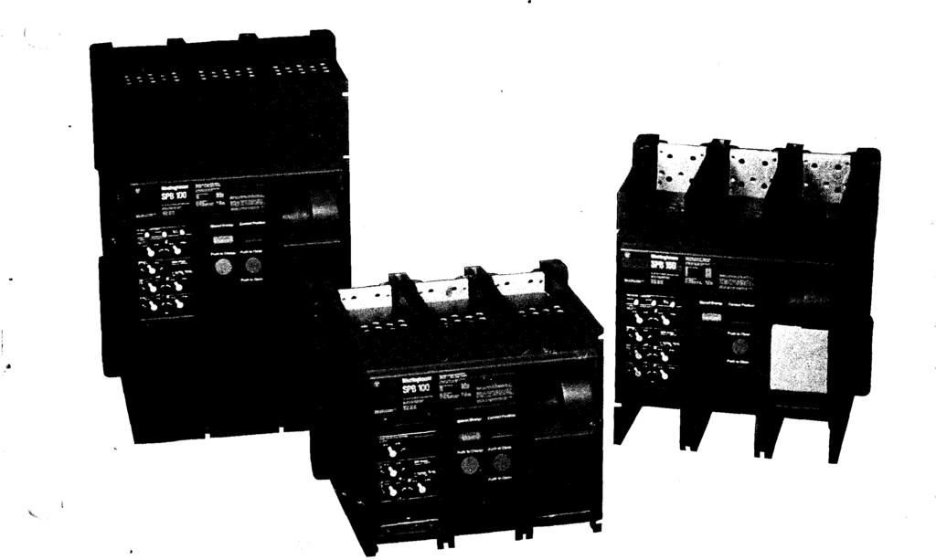
3 Description Breaker Series ,&--- Designation Stored Energy -- Condition Indicator Pow-R Trip 7 -- Trip Unit Interchangeable--- Rating Plug Sealable Transparent Trip Unit Cover The Systems Pow-R Breaker family consists of three physical frame sizes: 800, 1600 and 3000 amperes_ The 800 ampere frame covers ratings of 250 and 800 amps; the 1600 amp frame has a single rating of 1600 amps; and the 3000 amp frame includes ratings of 2000 and 2500 amps as well as 3000 amps. All three physical frames have the same width, depth and pole spacing with height being the only dimensional variation. Systems Pow-R Breakers are identified by four series: SPB-50, SPB-65, SPB-1 00 and SPB-150. The numbers after SPB refer to the interrupting capacity in RMS symmetrical amps at 480 volts Ac without fuses. Thus, in the SPB-1 00 series, any breaker from 250 to 3000 amps may be supplied with a U L Listed interrupting capacity of 100,000 amps at 480 volts Ac without fuses. Complete /.C. ratings are shown in Table A. Descriptive Bulletin Page 3 "iii--- Breaker frame Rating. -- Contact Position Indicator -- Electrical Push-to-Charge Button (Optional) Manual Operating Buttons (Standard) Charging Handle www. ElectricalPartManuals. com com


4 Page4 Standard Features UL Listing for 100% Application All Systems Pow-R Breakers are suitable for continuous operation at 100% of the frame rating. Thus, the Systems Pow-R Breaker, including the load side bus or cable, can be sized to the connected load, eliminating need for oversizing as with conventional overcurrent devices. Uniform Appearance, Compact Size All Systems Pow-R Breaker ratings-160 to 3000 amperes-have same depth, width and pole spacings for both manual and electrically operated units, permitting simplified bus arrangements and layout of assemblies. True Two-Step Stored Energy Mechanism Both mechanically and electrically operated versions feature a true two-step stored energy mechanism with no change in dimensions. This mechanism allows maximum five cycle closing usually required for generator paralleling Solid State Trip Unit Pow-R Trip 7 trip units for Systems Pow-R Breakers are solid state, totally enclosed devices that plug into the front of the breaker and are interchangeable between compatible breaker frames. Continuous Rating Rating plugs establish the nominal maximum continuous ampere rating of the breaker. They plug into the trip unit and are interchangeable between compatible trip units. Each of the three Systems Pow-R Breaker frame sizes features the same width and depth, whether manual or electrical operated. Safety Interlocking Systems Pow-R Breakers offer multiple layers of protective interlocking: (1) rating plugs and trip units are keyed to insure that they cannot be inserted in any trip unit or frame except the correct one: (2) attempting to remove a rating plug while the breaker is closed will trip the breaker; and (3) a breaker cannot be closed unless a rating plug is installed. Breaker Status Indicators Color coded visual indicators are provided to indicate position of contacts (Open or Closed), as well as status of closing springs (Charged or Discharged). Anti-Pump Provisions to prevent unwanted closing or reclosing operations when used with a maintained closed contact in the close circuit, anti-pump provisions are provided as standard on electrically operated breakers, and can be supplied on manually operated breakers with spring release solenoid. Common Wiring Diagram All Systems Pow-R Breakers use the same wiring diagram regardless of the number of attachments requested. The common wiring diagram simplifies the equipment assemblers' task of preparing his schematic diagram. Durability Systems Pow-R Breakers are capable of 4000 operations at rated load followed by 4000 operations at no load without maintenance. Ease of Maintenance Draw-out Systems Pow-R Breakers may be rotated 180 in fully withdrawn position for access to main and secondary disconnects. Main contacts and Pow-R Trip 7 sensor units are field replaceable. Main contacts Breaker being tilted out for inspection.


5 Operation Pow-R Trip 7 Solid State Trip Unit The solid state trip unit and sensor package is the heart of the Systems Pow-R Breaker. It provides the breaker's tripping function; it features up to seven time/current systemscoordination adjustments; it contains the rating plug which establishes the breaker's continuous ampere rating; and, as an option, it can provide up to three resettable visual indicators to define reason for breaker's tripping-overload, short-circuit, or ground fault. Trip units are interchangeable between compatible breaker frames. Trip Method Automatic breaker tripping operations are accomplished through the use of a special low-energy, flux-transfer shunt trip that requires no external control power. A conventional shunt trip device can be factory or field mounted if remote opening of the breaker is desired. Time/Current System Coordination Adjustments The standard Pow-R Trip 7 trip unit provides the following system coordination adjustments: adjustable ampere setting, adjustable long time delay, and adjustable instantaneous trip. Other adjustments available in various combinations with the standard adjustments are short time pick-up, short-time delay, ground fault pick-up and ground fault delay. For selective tripping applications, the instantaneous adjustment may be omitted when the short time adjustments are selected. All adjustments are made using non-removable, discrete step, high reliability switching plugs to assure positive, accurate adjustments. To Adjust: Pull Out Knob and Rot t To prevent tampering once the adjustment plugs have been set, the transparent cover over the face of the trip unit can be sealed. Rating Plugs The continuous ampere rating of Systems Pow-R Breakers is determined by a rating plug which is inserted in the trip unit. Rating plugs are available as listed below to permit close matching of the breaker and load side conductor to the actual load. Breaker Frame Ampere Rating Plug Ampere Ratings 200,225, ,400,500,600,700, ,1200, Descriptive Bulletin Page 5 The rating plug is interlocked with the tripping mechanism to automatically open the breaker when the plug is removed, and the breaker remains "trip free" until the plug is replaced. Rating plugs are interchangeable between compatible trip units, and are keyed to prevent their being inserted in incorrect trip units. Charging and Closing of Stored Energy Mechanism The two-step stored energy system employed by the Systems Pow-R Breaker provides maximum five cycle closing, either manually or electrically operated. The charging and closing actions in the mechanism utilize separate operating shafts, which allows design optimizing of the components in each portion of the mechanism. Manual charging of breaker Manual charging, above, is accomplished by a constant-force charging handle, using four full strokes or several partial inching strokes as desired. Electrical charging by a motor-driven operator is available as an option. Both manual and electrically operated breakers have multiple charge-close provisions which makes possible the charge-close-recharge-open-close-open sequence. As a safety feature, the stored energy can be discharged without closing the breaker. www. ElectricalPartManuals. com com

6 Page 6 Construction Features Continued Color coded status indicators on the breaker front cover, below, indicate stored energy condition and main contacts position. The stored energy indicator will not read "charged" until the mechanism is completely charged and ready to close. Closing operations, below, can be accomplished by a manual pushbutton on the breaker front, or by a remote close circuit using an optional spring release solenoid. Electrically operated breakers have anti-pump provisions as standard. The same anti-pump provisions are available as an option on manually operated breakers using spring release solenoids for remote closing operation. Table 1: Interrupting/Short-Time Ratings Series Frame Ampere Ratin g Short Time RatingCD Max. Short Time De lay@ Interrupting Capacity v 4Bov (ka rms symmetrical ) 6oo v -- SPB-50 SPB A 800 A 1600 A 251<A 25 KA 35 KA o Optional Systems Coordinating Adjustments Short Time Ratings Short time ratings are the key to systems coordination. Systems Pow-R Breaker short time ratings vary with the frame rating selected. Values of 25,000, 35,000 and 51,000 amps RMS Symmetrical are available (See Table 1 ). For selective coordination purposes, short time delay settings up to a maximum of 18 cycles (0.3 seconds) in three discreet steps are available. The design and test parameters of Systems Pow-R Breakers are based on a 600 volt distribution system with an X/R ratio of 6.6, which equates to a test power factor of 15%. In a system having these characteristics, the maximum peak offset in the first one-half cycle of a "worst case" condition can be as much as 2.3 times the RMS symmetrical value of the fault. By using these design parameters, no decrease in the specified short time ratings occur. 15% Power Factor Test Parameters The reason that the short time rating does not decrease is the unique optional selective override circuit of the Systems Pow-R Breaker. This feature differs greatly from instantaneous override or fixed instantaneous trip circuits. SPB A 800 A 1600 A 2000 A 2500 A 3000 A 25 KA 25 KA 35 KA 35 KA 35 KA 35 KA oo CD Short-time rating (rms symmetrical amps) in 600 V, 50/60-Hz system with X/R ratio of 6.6. Maximum short time delay setting in cycles. Instantaneous override or fixed instantaneous trip circuits respond only to a fixed RMS Symmetrical peak current, which equals the stated RMS symmetrical short time rating times (i.e. {2). These types of circuits are not capable of making allowances for the assymetrical offset which occurs in all faults and thus result in some decrease of their short time rating. The amount of derating is a direct factor of the system power factor. Tnp Point rvv0vvv\aa Instantaneous Override 1.414XI Symmetrical The selective override circuit in a Systems Pow-R Breaker allows the breaker to ride thru a fully offset fault within its short time rating. Selective coordination is provided with the down stream device which clears the fault, and continuity of service is maintained for all other unfaulted feeders. 1\l\l\1\l\l 2.3XI Symmetncol Trip limits Selective Override V\TV\TV \T X I Symmetncol Note: The selective override circuit is included in the Pow-R Trip 7 only when the instantaneous adjustment is omitted. In order to take full advantage of the outstanding Short Time Ratings and selectivity built into the Systems Pow-R Breaker, it is recommended that the Instantaneous adjustment be omitted in trip units including optional Short Time Adjustments. Should the adjustable instantaneous circuit be retained, the trip unit would respond at the peak value of the symmetrical current determined by the pick up setting and system selectively would be lost at a much lower value than is otherwise possible with selective override. 250 A 25 KA SPB A 1600 A 2000 A 2500 A 3000 A 25 KA 35 KA 51 KA 51 KA 51 KA www. ElectricalPartManuals. com com


7 Built-in Ground Fault Protection The Pow-R Trip 7 ground fault function features adjustable current pick-up settings to a maximum of 1200 amps, in accordance with the National Electrical Code. It also has adjustable time delays in three discreet steps with maximum breaker clearing times of 0.1, 0.3 and 0.5 seconds, and a memory circuit to compensate for the erratic nature of arcing ground faults. External terminations that can be reconnected are provided to satisfy the grounding conditions for simple and complex distribution systems. Residual is standard. Source ground connections are applicable, as is zero sequence with external sensors, in various physical configurations to match the system requirements. Integral Zone Selective Interlocking, a standard feature of the Systems Pow-R Breaker with Ground Fault, and available only from Westinghouse, is desirable for complex ground fault systems, such as hospitals where multiple levels of ground fault protection are required by the code. Multi-Layer Ground Fault Protection Scheme Using Zone Selective Interlocking With Zone Selective Interlocking, proper system coordination is maintained for down stream faults. To minimize equipment damage while providing the greatest degree of system continuity, the Zone Selective Interlocking system locates the fault and opens the nearest upstream breaker at the minimal time setting, regardless of preset settings, without losing coordination with upstream devices. Such a Joss of coordination could cause nuisance or unwanted tripping operations on the upstream devices. Descriptive Bulletin Page 7

8 Page 8 Optional Features Electrical Operation The electrical operator is mounted internally, with the result that there is no dimensional difference between manually and electrically operated units. Manually operated breakers are easily field convertible to electrical operation by adding a plug-in motor operator. UL Listing is not voided by field installation of motor operator. Motor Operator Motor operator installed in breaker Drawout Mounting Systems Pow-R Breaker drawout assemblies consist of a stationary frame and a moving carriage with four position stops: Connected, Test, Disconnected and fully withdrawn. Extension rails, the racking mechanism and operating handle are part of the draw-out Connected Position Breaker Front Test Position (Secondaries Only Engaged) D1sconnect Position Manual Rock-out Handle Rail Extension (Stored Position) Extension rail drawn-out assembly and are self-contained. The drawout mechanism is mechanically interlock.ed with the breaker drawout element, so that the breaker cannot be racked into or out of any position with its main contacts closed, or in the spring charged position. Padlocking of draw-out element For safety, breaker draw-out elements can be padlocked in any of the three draw-out positions, as well as in a tripped open position. Secondary contacts having a maximum of 48 points are located at the rear of the draw out element. Engagement of secondary contacts is assured by automatic self-alignment and positive contact of mating parts. Moving Secondary Contact Assembly Stationary Secondary Contact Assembly J

 that the breaker has tripped and also provides alarm and lock-out contacts.")
9 Trip Indicators Pow-R Trip 7 Trip Indicators Push to Reset Overlo d Ground. Short. Indication of automatic trip operation is optional on Systems Pow-R Breakers. Pow-R Trip 7 trip units are available with resettable indicators that indicate the reason the breaker tripped: overload, ground fault or short circuit. In addition, an automatic trip relay is available to indicate breaker tripping. One version of the relay indicates simply (by LED) that the breaker has tripped and also provides alarm and lock-out contacts. A second version of the relay indicates (by LED's) the cause of tripping (overload, ground fault or short circuit) as well as providing alarm and lock-out contacts. Automatic trip relay Door Mounted Breaker Drawout Position Indicators An external breaker position indicator is available for mounting on the breaker cell door to provide visual indication of the drawout position of the breaker behind the door. Breaker Connected Breaker in test position Breaker Disengaged Accessories In-service Testing A small hand held test kit permits functional testing of the breaker while it is in service. In addition, a separately mounted test panel is available for testing ground fault protective circuits. Mechanical Interlocking Mechanical interlocking of adjacent fixed or draw out breakers is available, as well as provision for key interlocking. Spring Release Solenoid For remote closing of a precharged breaker, a spring release is available. An auxiliary contact to denote spring charged position remotely is another feature furnished as standard with all spring release options. Other Available Accessories Shunt trip device Undervoltage release- Instantaneous Undervoltage release- Time Delay up to.5 seconds Auxiliary switches (six max) in combination of 2, 4 or 6 Make/Break arrangements. Provisions for blocking the manual "close" pushbutton Provisions for padlocking Cell switches U L Listed "deadfront" kit. Descriptive Bulletin Page 9 Padlocking push-to-open button Manual push-to-close button blocked off Dead-front kit in position To be Supplied by Others Dead Front Kit To be Supplied by Others www. ElectricalPartManuals. com com

10 Page 10 Application In formation (A} Curve Shaping Adjustments A maximum of seven curve shaping adjustments can be obtained on the Pow-R Trip 7. 1-o---FOI FW:. TI ::M n U SYSTEMS POW-R BREAKER TIME-CURRENT CURVE Pow-R Trip 7 Trip Device Adjustments: Ground Fault Pick up Ground Fault T1me Delay Data applies to all SPB breaker frame ratings Interrupting/Voltage/Short Time Ratings Refer to appropriate phase adjustment t1me-current curve and/or breaker nameplate: Curves apply from -20 C to +55 C ambient Zone Interlocking ( ) Zone selective interlocking supplied as standard with Pow R Trip 7 Trip devices. For a ground fault.n the immediate down stream zone of any breaker regardless of GF T1me Delay setting the breaker will revert to the "No Intentional" delay band. Refer to I.L for wiring modifications where 10terlocking is not desired. ii mm m j!!:!!;.. i ; 01 FOR FWAIIE RATINGS: loooa ] 1--- PICK UP SffiiNG AMPERES - Ground Fault Adjustments As the trip curve shows, adjustments can be made in discrete steps for: Ampere Setting: Adjustable in three steps; i.e. 80%, 90% and 100% of the rating plug Long Time Delay Bands:<D Adjustable at 600% current in three settings: Min: 2.2 seconds I nt: 7 seconds Max: 24 seconds Ground Time Delay Band:<D Adjustable in three steps: 0.1, 0.3 and 0.5 sees. (i.e. 6, 18 and 30 cycles). Ground Fault Pickup: For the 250, 800 and 1600 Amp. frame there are six discrete settings based on the frame ratings:.2,.3,.4,.5,.6 and.75 times the frame rating AIIPEIIS IN MULTII'lES Of PLUG RATING f--- AMPERES IN MULTIPLES OF PLUG RATING Phase Adjustments For the 2000, 2500 and 3000 Amp. frames there are five discreet settings at 600, 750, 900, 1050 and 1200 Amps. Short Delay Pickup: Adjustable to 2, 4, 6 or 8 times the rating plug Short Time Delay Bands:<D Adjustable in three steps 0.1, 0.2 and 0.3 seconds (i.e. 6, 12 and 18 cycles) Instantaneous Pickup: Adjustable at 2, 4, 6, 8 or 10 times the rating plug CD Time value adjustments are calibrated points and denote "'total clearing times. L-" "''"'""'"'" Override supplied only when Instantaneous Adjustment is omitted. (Set at 35KA RMS Symmetrical) Curves apply from -20 C to +55 C Ambient Condition "A" Initial Fault Peak exceeds Short Time Current RMS Symmetrical Rating X 2.3 Condition "B" After at proximately two cycles, Condition "A" did not occur but fault persists and exceeds RMS Symmetrical Short Time Rating. Interruption Ratings 50/60 Hertz RMS Symmetrical KA Series Frame Amps SPB V V V 50 SPB 100 SPB ISO Amperes i ii I
11 Typical Specification for the Systems Pow-R Breaker Circuit breakers shall be encased Westinghouse Systems Pow-R Breakers. All breakers shall be U L Listed for application in their intended enclosure for 100% of their continuous ampere rating. Frame ampere ratings shall be 250, 800, 1600, 2000, 2500, or 3000 amperes as shown on the drawings. The amperes interrupting capacity (I.C.) and short time ratings shall be as follows: SPB-50 (250/800 Amp. Frame) I. C.: 50,000 amps at 480 volts Short Time Rating: 25,000 amps (RMS Sym.) SPB-65 (1600 Amp. Frame) I. C.: 65,000 amps at 480 volts Short Time Rating: 35,000 amps (RMS Sym.) SPB-100 (250/800/1600/2000/2500/ 3000 Amp. Frame) I. C.: 100,000 amps at 480 volts without fuses Short Time Rating: 25,000 amps (RMS Sym.) for 250 and 800 amp. frame; 35,000 amps (RMS Sym.) for 1600 amp. and above. SPB-150 (250/800/1600/1200/2500/ 3000 Amp. Frame) I.C.: 150,000 amps at 480 volts without fuses Short Time Rating: 25,000 amps (RMS Sym.) for 800 amp. frame; 35,000 amps (RMS Sym.) for 1600 amp. frame 51,000 Amps (RMS Sym.) for 2000 Amp. Frame and larger Short time ratings shall be based on a 600 volt, 50/60Hz system with an X/R ratio of 6.6. A selective override circuit shall be provided on breakers having short time adjustments, but without instantaneous adjustments that will allow the breaker to be applied at its maximum interrupting capacity while providing full selectivity up to its RMS Symmetrical short time rating. All breakers shall be provided with a true, two-step stored energy mechanism which allows closing in a maximum of 5 cycles whether the breaker is manually or motor operated. Both manual and motor operated breaker shall have identical physical dimensions. Manually operated breakers shall be field convertible to motor operation without voiding the U L label on it. As a safety feature, anti-pump provisions shall be provided as standard for motor operated breakers and optional for manual breakers with spring release solenoids. Both manual and motor operated breakers shall have multiple charge/ close provisions providing the following sequence: Charge-Close-Recharge-Open Close-Open. The breaker control face plate shall include color coded visual indicators to indicate contact and stored energy status. Local control push buttons shall be provided for opening and "closing" the breaker. For motor operated breakers, a local "charge" pushbutton shall be provided as standard. The continuous ampere rating of the breaker shall be determined by the insertion of an interchangeable rating plug that matches the load and cable requirements. The rating plug shall be interlocked with the tripping mechanism to automatically "open" the breaker when the plug is removed. The breaker shall remain "trip free" with the plug removed. In addition, rating plugs shall be keyed to prevent incorrect application between different frame ratings. Complete system selective coordination shall be provided by the addition of the following time/current curve shaping adjustments: (1) Ampere Setting (2) Long Time Delay (3) Short Time Pickup (4) Short Descriptive Bulletin Page 11 Time Delay (5) Ground Fault Pickup (6) Ground Fault Time Delay. All adjustments shall be made using non-removable discreet step, high reliability switching plugs for precise settings. A sealable transparent cover shall be provided over the adjustments to prevent tampering. Ground fault protection shall be provided as an integral part of the breaker. A ground fault memory circuit shall be provided to compensate for the erratic nature of arcing ground faults and provide for positive tripping actions. A residual scheme shall be used as standard for detecting ground fault currents. Where more complex systems require alternate sensing methods, the Pow-R Trip 7 shall be reconnectable for either a source ground or zero sequence detection scheme as required. Integral Zone Selective Interlocking shall be provided as a standard feature. The Pow-R Trip 7 devices shall be provided with up to three visual indicators to indicate the automatic tripping mode of the breaker (i.e. Overload, Short Circuit or Ground Fault). In addition the Pow-R Trip devices shall be provided with terminals that can be wired to an optional remote auxiliary package to provide the above type of indication. A separate mounted test panel shall be available to permit the testing of the ground fault circuit by either tripping the breaker or not tripping the breaker. All breakers shall be provided with test points for in-service functional testing of the long time, instantaneous and ground fault circuits by means of a small hand held test kit. The breakers shall be capable of a minimum of 4000 interruptions of rated current followed by 4000 operations at no load without maintenance. Further, the breaker shall be equipped with field replaceable contacts.
12 Page 12 Dimensions, Inches Not to be used for construction purposes unless approved. SPB Breakers, Fixed Mounted r-15l I : 2 -w n-r T 12 1 I 13-1 Line End [] S'J HP-:: lj _HL-r----' '--"-.=..1 I Load End 250 and 800 Amp (Fixed Front and Rear Connected) f. 3.! J Amp (Fixed Front Connected) Line End ft j_ t I I 13 Line End 1600 Amp (Fixed Front and Rear Connected) I _I -I 3000 Amp (Fixed Rear Connected) Line End --- L--L J Load End
13 I Dimensions, Inches Not to be used for construction purposes unless approved. SPB 800 Ampere Breaker for Drawout Mounting Metenng Current Transformers Space for Use w1th Wesflnghouse Type CLA-10 or Type LRM-10 Inside Edge of Cover Ratchet Pulls Out to Operate \ Disconnected Posit1on Main and Secondary Contacts Open Test Pos1tion 24 Main Contacts Open and t 5 26j \ Secondary Contacts Closed Connected Pos1t1on Mmn and Secondary Contacts Closed Room Required to Remove Key Current Transformers Must be Ordered Separately -OpfiOn- 2 on L1ne End Outside Poles 1 on Load End Center Pole Secondary Contacts (When Requ eed I J r j%---:, t T D1mension over Brace and Transformer Note: Descriptive Bulletin Page 13 't_ of Breaker and Mechanism Suitable for Continuous Operation at 80% of Key Interlock Option i'fli--h'-ir-t---f---'i-h-h-'t_ of Breaker and Mechanism Frame Rating in an Enclosure Without Ventilation Suitable for Continuous Operation at 100% of Frame Rating if Used in a Minimum Enclosure 14 l!z Inches High X 21 Inches Wide X 331!2 Inches Deep. (Ventilation is not Required)
14 Page 14 Dimensions, Inches Not to be used for construction purposes unless approved. SPB 1600 Ampere Breaker for Drawout Mounting Meterinq Current Transformers Space for Use with Westinghouse Type CLA-10 or Type LRM-10 Inside Edge of Cover Ratchet Pulls Out to Operate --\!--1o- D1sconnected Position MOin and Secondary Contacts Open i \ Room Required to Remove Key Test Position Main Contacts Open and Secondary Contacts Closed Connected Position M01n and Secondary Contacts Closed Current Transformers Must be Ordered Separately-Option- 2 on Line End Outside Poles 1 on Load End Center Pole J.., 21 Note: ct._ of Breaker and Mechanism 0 0 Suitable for Continuous Operation at 80% of 0 Key Interlock Option ct._ of Breaker and Mechanism Frame Rating in an Enclosure Without Ventilation. Suitable for Continuous Operation at 100% of Frame Rating if Used in a Minimum Enclosure 22 Inches High X 21 Inches Wide X Inches Deep (Ventilation is not Required)
15 Dimensions, Inches Not to be used for construction purposes unless approved. SPB 3000 Ampere Breaker for Drawout Mounting Metering Current Transformers Space for Use wrth lc ===: ;; ;;;:!!== Westinghouse Type CLA-10 or Type LRM-10 lnsrde Edge of Cover Ratchet Pulls Out to Ope rote Drsconnected Positron Main and Secondary Contacts Open 24 ll \ Room Required to Remove Key 29 Test Position Main Contacts Open and Secondary Contacts Closed Connected Position Main and Secondary Contacts Closed I----26B I l ---- Current Transformers Must be Ordered Separately -Option- 2 on Line End Outside Poles 1 on Load End Center Pole J, ii _ _ Note: Descriptive Bulletin Page 15 ctof Breaker and Mechonrsm Suitable for Continuous Operation at 80% of Key Interlock Option Frame Rating in an Enclosure Without Ventilation Suitable for Continuous Operation at 100% of Frame Rating if Used in a Minimum Enclosure 36 Inches High X 21 Inches Wide X 38 Inches Deep With Minimum Ventilation of 160 Square It_ of Breaker and Mechonrsm Inches in Either The Front or Side of The Enclosure. <t_ of Breaker and Mechonrsm f www. ElectricalPartManuals. com com 8 l 16

16 Descriptive!3ulletin Page 16 Approximate We ights, Lbs. Frame Fixed Drawout Mounted Rating Mounted Breakers Amperes Breakers Drawout Drawout Element Stationary Only Frame Further Information List Prices: Price List Westinghouse Electric Corporation Low Voltage Breaker Division Beaver, Pennsylvania U.s.A ,, www. ElectricalPartManuals. com com " " a; Q_ " c (/) J>
A. Submit manufacturer's literature and technical data before starting work.
 SECTION 16425 SWITCHBOARD PART 1 GENERAL 1.01 SUMMARY A. Related Section: 1. 16450 - Grounding. 1.02 SUBMITTALS A. Submit manufacturer's literature and technical data before starting work. B. Submit Shop
DIVISION 26 ELECTRICAL SECTION CIRCUIT BREAKERS
 DIVISION 26 ELECTRICAL SECTION 26 28 19 PART 1 GENERAL 1.01 DESCRIPTION A. Furnish and install circuit breakers in switchboards, distribution panelboards, and separate enclosures for overcurrent protection
SECTION MICROPROCESSOR TRIP UNITS FOR LV CIRCUIT BREAKERS. This section is organized as indicated below. Select desired Paragraphs.
 SECTION 16904 MICROPROCESSOR TRIP UNITS FOR LV CIRCUIT BREAKERS PART 2 PRODUCTS 01 MANUFACTURERS A. B. C. Eaton * * The listing of specific manufacturers above does not imply acceptance of their products
Section SWITCHBOARDS. Introduction. Part 1 - General. Related Work
 Section 16435 - SWITCHBOARDS Introduction Part 1 - General Related Work Section 16070 Seismic Anchorage and Restraint Section 16075 Electrical Identification Section 16080 Power Distribution Acceptance
Medium Voltage Standby non-paralleling Control GUIDE FORM SPECIFICATION
 Medium Voltage Standby non-paralleling Control 1. GENERAL GUIDE FORM SPECIFICATION A. The requirements of the contract, Division 1, and part 16 apply to work in this section. 1.01 SECTIONS INCLUDE A. Medium
A. This Section includes Low Voltage Switchgear Work, as indicated on the drawings, and as specified herein.
 16425 SWITCHBOARD ************************************************************************************************************* SPECIFIER: CSI MasterFormat 2004 number: 26 24 13 An optional keynote to
DESIGN GUIDELINES LOW VOLTAGE SWITCHGEAR PAGE 1 of 5
 DESIGN GUIDELINES LOW VOLTAGE SWITCHGEAR PAGE 1 of 5 1.1. APPLICABLE PUBLICATIONS 1.1.1. Publications listed below (including amendments, addenda, revisions, supplements, and errata), form a part of this
Data Bulletin. Ground-Censor Ground-Fault Protection System Type GC Class 931
 Data Bulletin 0931DB0101 July 2001 Cedar Rapids, IA, USA Ground-Censor Ground-Fault Protection System Type GC Class 931 09313063 GT Sensor Shunt Trip of Circuit Interrupter Window Area for Conductors GC
Selective Coordination
 Circuit Breaker Curves The following curve illustrates a typical thermal magnetic molded case circuit breaker curve with an overload region and an instantaneous trip region (two instantaneous trip settings
SECTION ENCLOSED SWITCHES AND CIRCUIT BREAKERS
 SECTION 26 28 16 ENCLOSED SWITCHES AND PART 1 - GENERAL 1.1 SUMMARY A. Section includes the following individually mounted, enclosed switches and circuit breakers rated 600V AC and less: 1. Fusible switches.
A. Work Included: Provide low voltage switchboard work as shown, scheduled, indicated, and as specified.
 SECTION 26 24 13 LOW VOLTAGE SWITCHBOARDS PART 1 - GENERAL 1.1 RELATED DOCUMENTS: A. The Conditions of the Contract and applicable requirements of Divisions 0 and 1 and Section 26 00 01, Electrical General
APPENDIX E. Electrical System Single Line Diagram Overcurrent Protection Study Overcurrent Protection Device Specifications
 Student Resource Building University of California Santa Barbara Clement Fung Lighting Electrical Option APPENDIX E Electrical System Single Line Diagram Overcurrent Protection Study Overcurrent Protection
Medium Voltage Metal-Enclosed Switches
 Medium Voltage Metal-Enclosed Switches Outdoor Medium Voltage Switch.1 Medium Voltage Switch MVS Product Description............................................. 2 Application Description..........................................
A system fault contribution of 750 mva shall be used when determining the required interrupting rating for unit substation equipment.
 General Unit substations shall be 500 kva minimum, 1500 kva maximum unless approved otherwise by the University. For the required configuration of University substations see Standard Electrical Detail
Cutler-Hammer May 2001
 Low-Voltage Power Circuit Breakers Magnum DS General Description Index Page General Description Magnum DS............. A1-1 General Description DSII/DSLII............... A1-7 Technical Data Magnum DS.
Michigan State University Construction Standards SECONDARY UNIT SUBSTATIONS PAGE
 PAGE 261116-1 SECTION 261116 PART 1 - GENERAL 1.1 RELATED DOCUMENTS A. Drawings and general provisions of the Contract, including General and Supplementary Conditions and Division 01 Specification Sections,
Critical Power Switchboards. Selection and Application Guide
 Selection and Application Guide Siemens RCIII (rear connected) switchboards utilizing Siemens Type SB Encased Breakers are a perfect solution for your critical power distribution needs. Whether your installation
Metal-Enclosed Switches. Medium Voltage. Medium Voltage Metal-Enclosed Switches Contents
 January 2003 Vol. 1, Ref. No. [1011] -1 Medium Voltage Metal-Enclosed Switches Contents Description Page MVS................................... -2 and Breaker MSB........................ -3 Metal-Enclosed
Medium Voltage Metal-Enclosed Switches
 Medium Voltage Metal-Enclosed Switches Outdoor Medium Voltage Switch.1 Introduction Product Selection Guide....................................2 Medium Voltage Switch MVS Product Description......................................
MAGNETIC MOTOR STARTERS
 Chapter 6 MAGNETIC MOTOR STARTERS 1 The basic use for the magnetic contactor is for switching power in resistance heating elements, lighting, magnetic brakes, or heavy industrial solenoids. Contactors
www. ElectricalPartManuals. com Systems Pow-R Breaker Transfer Switches Technical Data Page 1
 Cl November 1984 New Information Mailed to: E, D, C/29-900A Westinghouse Electric Corporation Distribution and Protection Business Unit Commercial Division - Assemblies London, KY 407 41 Technical Data
www. ElectricalPartManuals. com Instructions for Field Testing of Ground Fault Systems Utilizing Cutler-Hammer Magnum DS Circuit Breakers
 Instructions for Field Testing of Ground Fault Systems Utilizing Cutler-Hammer Magnum DS Circuit Breakers The National Electrical Code makes the following statement regarding ground fault conformance testing:
University of Houston Master Construction Specifications Insert Project Name
 SECTION 26 13 13 MEDIUM VOLTAGE SWITCHGEAR PART 1 - GENERAL 1.1 RELATED DOCUMENTS: A. The Conditions of the Contract and applicable requirements of Divisions 0 and 1 and Section 26 00 01, Electrical General
Modular Metering - Trip Unit for >1200A Mains DEH41187 Application Guide
 GE Industrial Solutions Modular Metering - Trip Unit for >1200A Mains DEH41187 Application Guide TABLE OF CONTENTS Description Page 1.0 General Information...... 1 1.1 Protection..... 1 2.0 UL Listed Devices...
SECTION DC POWER SUPPLY/BATTERY CHARGER
 SECTION 26 33 05 PART 1 - GENERAL 1.1 THE REQUIREMENT A. The CONTRACTOR shall provide the single-phase heavy-duty industrial battery charger and all accessories required, complete and operable, in accordance
Cutler-Hammer. Installation Instructions for the Digitrip OPTIM Pole Trip Unit Installation and Operation with L-Frame Series C Circuit Breakers
 Cutler-Hammer Installation Instructions for the Digitrip OPTIM 550 3-Pole Trip Unit Installation and Operation with L-Frame Series C Circuit Breakers Table of Contents Description Page 1.0 General Information......................1
IN2 Enclosed Switches and Circuit Breakers
 Illinois Math and Science Academy DigitalCommons@IMSA Project Manuals IN2 2015 IN2 Enclosed Switches and Circuit Breakers Illinois Mathematics and Science Academy Follow this and additional works at: http://digitalcommons.imsa.edu/facility_in2_manuals
Power Break II Switchboard
 Power Break II Switchboard Now available with PowerBreak II Circuit Breakers through 4000A GE s Power Break II Switchboard is now available with the new Power Break II Insulated Case Circuit Breaker (800A
TYPES DS II AND DSL II METAL ENCLOSED LOW VOLTAGE POWER CIRCUIT BREAKERS
 om.c ww w.e lec tri ca lp ar tm an ua ls TYPES DS II AND DSL II METAL ENCLOSED LOW VOLTAGE POWER CIRCUIT BREAKERS Proven Technology with the Enhancements and Additional Ratings Our Customers Asked For
GE Consumer & Industrial Electrical Distribution. Power Break II. Insulated Case Circuit Breakers
 GE Consumer & Industrial Electrical Distribution Power Break II Insulated Case Circuit Breakers Table of Contents Power Break II Circuit Breakers......................... 3 Basic Configuration.......................................
ABB Power T&D Company Inc. Relay Division Coral Springs, FL Allentown, PA. Non-Directional, Single Phase Adjustable Time Delay Device No.
 September, 1990 Supersedes Descriptive Bulletin 41-100, pages 1-4, dated June, 1989 Mailed to: E, D, C/41-100A Hi-Lo co induction-disc type overcurrent relays are activated when the current in them exceeds
Horizontal Circuit Switchers
 > Transformer Protection > CIRCUIT SWITCHERS C A T A L O G B U L L E T I N General Application Southern States Types CSH and CSH-B Horizontal Circuit Switchers provide an economical, versatile, space saving
University of Houston Master Construction Specifications Insert Project Name SECTION ELECTRONIC VARIABLE SPEED DRIVES PART 1 - GENERAL
 SECTION 23 04 10 ELECTRONIC VARIABLE SPEED DRIVES PART 1 - GENERAL 1.1 RELATED DOCUMENTS: A. The Conditions of the Contract and applicable requirements of Division 1, "General Requirements", and Section
SIEMENS. Series 8100oT Vacuum Controllers. www. ElectricalPartManuals. com. Bulletin CC
 c c SIEMENS Series 8100oT Vacuum Controllers Bulletin CC3802-02 Technological Development Vacuum technology has developed rapidly in recent years and is becoming widely accepted for medium voltage motor
Specification Guide. for RMAX. Direct Replacement. AC Low Voltage. Power Circuit Breakers
 Specification Guide for RMAX Direct Replacement AC Low Voltage Power Circuit Breakers Table of Contents 1.0 General Work Scope...3 2.0 Standards... 3 3.0 Supplier Qualifications... 3 4.0 Mechanical and
University of Houston Master Construction Specifications Insert Project Name
 SECTION 26 24 14 600 VOLT DRAWOUT SWITCHGEAR PART 1 - GENERAL 1.01 SECTION INCLUDES: A. Individually mounted rear-accessible low voltage switchgear ANSI rated switchgear and low voltage power circuit breakers
MULTI 9 System Catalog IEC Rated C60N/H/L Circuit Breakers
 IEC Rated C60N/H/L Circuit Breakers Standard Features Fast Closing Allows increased withstand to the high inrush currents of some loads Trip-free mechanism: Contacts cannot be held in the on position when
AP/UP, AP/MIL Series Magnetic Circuit Protectors
 AP/UP, AP/MIL AP/UP, AP/MIL Series Magnetic Circuit Protectors Introduction 68 Single Pole 69 Multi-Pole 70 Configurations 72 Operating Characteristics 73 Delay Curves 74 Specifications 75 Decision Tables
www. ElectricalPartManuals. com TRI-PAC circuit breakers current limiting protectors for. lighting, power and distribution circuits
 desoriptioa The TR-PAC breaker is essentially an AB De-ion 19 circuit breaker incorporating a current-limiting device which enables it to be used on distribution systems where fault currents up to 1, symmetrical
ACS motor protection circuit breakers KT 7 Introduction
 Introduction Automatic Type 2 coordination The right circuit breaker for all applications The KT 7 circuit breaker family consists of two basic frame sizes of mm and 5 mm in three variations with different
Mar H: SUPPLEMENTAL PARALLELING GEAR (16315-H)
") 2101 Commonwealth Blvd, Suite B Ann Arbor, MI 48105-5759 www.med.umich.edu/facilities/plan/ 263010-H: SUPPLEMENTAL PARALLELING GEAR (16315-H) Related Sections Basis Guideline: N/A For an explanation of
2101 Commonwealth Blvd, Suite B Ann Arbor, MI 48105-5759 www.med.umich.edu/facilities/plan/ 263010-H: SUPPLEMENTAL PARALLELING GEAR (16315-H) Related Sections Basis Guideline: N/A For an explanation of
Switchgear. Low Voltage
 January 2001 Vol. 1, Ref. No. [0923] -1 Low Voltage Switchgear Contents Description Page Magnum DS Metal-Enclosed Product Description........................................... -2 Application Description........................................
S&C TripSaver II. Cutout-Mounted Recloser. For enhanced lateral circuit protection at 15 kv and 25 kv
 TripSaver II Cutout-Mounted Recloser For enhanced lateral circuit protection at 15 kv and 25 kv Introducing s new TripSaver II Cutout-Mounted Recloser: A better solution for overhead lateral circuit protection
Bolted contact switches. Pringle switches
 Bolted contact switches Pringle switches Eaton s Pringle bolted contact switches History Eaton s PringleT switches have helped pioneer the development of high-quality electrical products for commercial
Single Pole Circuit Protectors 55. Multi-Pole Circuit Protectors 56. Configurations 58. Operating Characteristics 59.
 Single Pole Circuit Protectors 55 Multi-Pole Circuit Protectors 56 Configurations 58 Operating Characteristics 59 Delay Curves 60 Specifications 61 Decision Tables 62 SINGLE POLE CIRCUIT PROTECTORS The
Magnum IEC Low Voltage Air Circuit Breakers
 Magnum IEC Low Voltage Air Circuit Breakers Product Focus Up to 690 Vac 42 ka to 100 ka Icu 800 to 6300 Amperes EN 60947-2 A Global Source for Innovative Electrical Power Distribution Solutions Proven
DENVER PUBLIC SCHOOLS DESIGN AND CONSTRUCTION STANDARDS This Standard is for guidance only. SECTION MOTORS, STARTERS & DRIVES
 PART 0 DESIGN STANDARDS 0.01 GENERAL DESIGN GUIDELINES A. Coordinate starter needs for mechanical equipment prior to 50% CD and confirm again for 100% CD submittal. B. Coordinate temperature controls requirements
Horizontal Circuit Switchers
 > Transformer Protection > CIRCUIT SWITCHERS C A T A L O G B U L L E T I N General Application Southern States Types CSH and CSH-B Horizontal Circuit Switchers provide an economical, versatile, space saving
Controlled Power HSN High Speed DC Circuit Breakers
 Controlled Power HSN High Speed DC Circuit Breakers Each CP Type HSN circuit breaker unit can consist of either a wheeled truck and housing or be panel mounted. The circuit breaker can be mounted on the
The University of New South Wales. School of Electrical Engineering and Telecommunications. Industrial and Commercial Power Systems Topic 6
 The University of New South Wales School of Electrical Engineering and Telecommunications Industrial and Commercial Power Systems Topic 6 PROTECTIONS 1 FUNCTION OF ELECTRICAL PROTECTION SYSTEMS Problems:
Westinghouse Electric Corporation Distribution and Control Business Unit Assemblies Division Bloomington, Indiana
 Supersedes Descriptive Bulletin, pages 1-8, dated January, 1976 Mailed to: E, D, C/38-000F Westinghouse Electric Corporation Distribution and Control Business Unit Assemblies Division Bloomington, Indiana
Solid Dielectric, Single Phase Recloser
 Solid Dielectric, Single Phase Recloser Catalog O-vsp17 Viper-SP Viper-SP solid dielectric, single phase recloser combines the time-proven reliability of electronically controlled, vacuum fault interrupters
1. The term "withstand" means "the unit will remain in place without separation of any parts from the device when subjected to the seismic forces.
 SECTION 262816 - ENCLOSED SWITCHES AND CIRCUIT BREAKERS PART 1 - GENERAL 1.1 SUMMARY A. Section Includes: 1. Fusible switches. 2. Nonfusible switches. 3. Receptacle switches. 4. Shunt trip switches. 5.
16kA Solid Dielectric, Triple Option Reclosers Catalog VLT12
 16kA Solid Dielectric, Triple Option Reclosers Providing electronic overcurrent protection for single or three phase operation on systems rated through 27kV, 630A continuous current, 16kA symmetrical interrupting
Specification for 70mm pole pitch Air circuit breaker up to 1600 A
 Specification for 70mm pole pitch Air circuit breaker up to 1600 A Protective device for low voltage electrical installation Last update :2011-07-08-1 - Table of contents: 1 General...3 2 Compliance with
UNIVERSITY OF WASHINGTON Facilities Services Design Guide. Electrical. Switchboards. Basis of Design. Design Evaluation
 Basis of Design This section applies to the design relating to low voltage switchboards. Design Criteria UW Class N1 facilities main switchboards shall be rear accessible. The main, tie and feeder breakers
www. ElectricalPartManuals. com Section 13 Switchgear Low Voltage
 Switchgear Low Voltage Introduction...13-1 AKD-10 Low-Voltage Switchgear...13-3 AKD-20 Low-Voltage Switchgear...13-3 Low Voltage Switchgear GE low-voltage switchgear is heavy-duty equipment built to ANSI
Low Voltage Switchgear Type WL Low Voltage Metal-Enclosed Switchgear
 13 Low Voltage Switchgear Siemens Type WL low voltage metal-enclosed switchgear is designed, constructed and tested to provide superior power distribution, power monitoring and control. At the heart of
SECTION MOTOR CONTROL
 SECTION 26 24 19 MOTOR CONTROL PART 1 - GENERAL 1.1 SECTION INCLUDES A. Manual motor starters B. Magnetic motor starters C. Combination magnetic motor starters D. Solid-state reduced voltage motor starters
2018 Consultant s Handbook Division 26 Electrical 2413 Switchboards
 1 General 1.1 Switchboards shall be U.L. listed and labeled. 1.2 Each switchboard shall have its own main disconnecting means unless it is located in the same room as its source of origin. In most cases
3.2. Current Limiting Fuses. Contents
 .2 Contents Description Current Limiting Applications................. Voltage Rating.......................... Interrupting Rating....................... Continuous Current Rating................ Fuse
www. ElectricalPartManuals. com lncoming-6900 through 69,000 volts Outgoing-2400 through 13,800 volts Ratings:
 PRIMARY UNIT SUBSTATIONS SECTION 2701 PRIMARY UNIT SUBSTATIONS Ratings: lncoming-6900 through 69,000 volts Outgoing-2400 through 13,800 volts PAGE 1 ---JUNE 1, 1959 DESIGNED AND BUILT TO MEET YOUR OWN
UBC Technical Guidelines Section Edition Commissioning of Electrical Systems Page 1 of 5
 Page 1 of 5 1.0 GENERAL 1.1 Coordination Requirements.1 UBC Building Operations Electrical Technical Support.2 UBC Energy & Water Services 2.0 REQUIREMENTS FOR COMMISSIONING AND TESTING 2.1 Testing.1 Unit
Design Standard. Purpose: Design Standard:
 Design Standard Purpose: This design standard has the purpose of creating a consistent application of motor-control centers throughout the East Side Union High School District, therefore achieving a standard
A. Provide a complete system of overcurrent protective devises as indicated on the drawings, and as specified herein.
 16475 OVERCURRENT PROTECTIVE DEVICES ************************************************************************************************************* SPECIFIER: CSI MasterFormat 2004 number: 26 28 16 An optional
17.1. Low Voltage Switchgear. For Immediate Delivery or Tech Support call KMParts.com at (866) Contents
 Contents") .1 Low Voltage Switchgear Magnum DS Metal-Enclosed Magnum DS Switchgear with Molded Case Circuit Breaker Feeder Section Cross-Reference Eaton s Electrical Sector has an organization dedicated to the support
.1 Low Voltage Switchgear Magnum DS Metal-Enclosed Magnum DS Switchgear with Molded Case Circuit Breaker Feeder Section Cross-Reference Eaton s Electrical Sector has an organization dedicated to the support
SURE TRIP RETRO KITS
 RMS CURRENT MEASUREMENT with SURE TRIP RETRO KITS Circuit Breaker Solid State Controls with SURE TRIP LOGIC The Sure Trip Solid State Tripping Systems Have Been Designed, Tested And Produced To all Applicable
GTEC Transfer switch Open transition
 GTE Transfer switch Open transition 40-2000 amp Description GTE transfer switches combine reliability and flexibility in a small, economical package for transferring loads between a utility and a generator
PowerPact M-, P- and R-Frame, and Compact NS630b NS3200 Circuit Breakers
 PowerPact M-, P- and R-Frame, and Compact NS630b NS3200 Circuit Breakers Catalog 0612CT0101 R02/14 2014 Class 0612 CONTENTS Description............................................. Page General Information..........................................
White Paper. Ground Fault Application Guide. WL Low Voltage Power Circuit Breakers
 White Paper Ground Fault Application Guide WL Low Voltage Power Circuit Breakers Table of Contents Introduction 3 Need for ground fault tripping 3 Requirements from industry standards 3 National Electrical
Solid Dielectric, Three Phase Reclosers CATALOG VS11
 Solid Dielectric, Three Phase Reclosers Providing electronic, three phase overcurrent protection for systems rated through 38kV, 800A continuous current, 12.5kA symmetrical interrupting Reliable performance
GE Consumer & Industrial. M-PACT New Air Circuit Breaker A
 GE onsumer & Industrial M-PT New ir ircuit reaker 400-4000 M-PT M-PT ir ircuit reaker 400-4000 1 ir circuit breakers 400-4000.4 Fixed ircuit reaker.6 Withdrawable ircuit reaker.7 haracteristics.9 State
Solid Dielectric, Triple Option Reclosers Catalog O-vlt14
 Solid Dielectric, Triple Option Reclosers Providing electronic overcurrent protection for single or three phase operation on systems rated through 27kV, 630A or 800A continuous current, 12.5 or 16kA symmetrical
SECTION PANELBOARDS
 SECTION 16470 PANELBOARDS PART 1 - GENERAL 1.1 RELATED DOCUMENTS A. The general provisions of the contract including General and Special Conditions and General Requirements shall apply to all work under
ABB. Type CRQ Directional Negative Sequence Relay for Ground Protection B 1.0 APPLICATION 2.0 CONSTRUCTION AND OPERATION CAUTION
 ABB Instruction Leaflet 41-163.2B Effective: January 1977 Supersedes I.L. 41-137.3A, Dated September 1974 ( ) Denotes Change Since Previous Issue Type CRQ Directional Negative Sequence Relay for Ground
CONTROLLIX CORPORATION CONTROLLIX.COM LOW VOLTAGE AUTOMATIC SWITCH CAPACITOR BANK SPECIFICATIONS
 LOW VOLTAGE AUTOMATIC SWITCH CAPACITOR BANK SPECIFICATIONS I. SCOPE a. This specification describes the necessary requirements for the design, fabrication, and operation of automatically switched, low
A. Provide variable frequency drives to operate variable torque loads as shown on the Drawings and as specified herein.
 DIVISION 23 HEATING, VENTILATING, AND AIR CONDITIONING (HVAC) SECTION 23 90 71 PART 1 GENERAL 1.01 DESCRIPTION A. Provide variable frequency drives to operate variable torque loads as shown on the Drawings
Typical Specification
 Engineered to Order Built to Last Typical Specification VAULT VRPFI, TWO POSITION, ROTARY PUFFER SWITCHGEAR PART 1- GENERAL 1.1 DESCRIPTION A. The switch shall consist of manually operated load interrupting,
A. This Section includes ac, enclosed controllers rated 600 V and less, of the following types:
 SECTION 262913 600 VOLT ENCLOSED CONTROLLERS PART 1 - GENERAL 1.1 RELATED DOCUMENTS A. Drawings and general provisions of the Contract, including General and Supplementary Conditions and Division 0 Specification
OTEC Transfer switch open transition
 Specification sheet OTEC Transfer switch open transition 40 1200 amp Description OTEC transfer switches are designed for operation and switching of electrical loads between primary power and Standby generator
SECTION MOTOR CONTROLLERS
 PART 1 - GENERAL 1.1 DESCRIPTION SECTION 26 29 11 MOTOR CONTROLLERS SPEC WRITER NOTE: Delete between // ---- // if not applicable to project. Also, delete any other item or paragraph not applicable to
Chapter 6 Generator-Voltage System
 Chapter 6 Generator-Voltage System 6-1. General The generator-voltage system described in this chapter includes the leads and associated equipment between the generator terminals and the low-voltage terminals
SECTION LOW VOLTAGE DISTRIBUTION EQUIPMENT
 SECTION 16400 LOW VOLTAGE DISTRIBUTION EQUIPMENT A. General 1. The University does not accept Series-Rated equipment for power distribution switchboards, distribution panels and branch circuit panelboards.
Transfer switch OTEC open or delayed transition
 Transfer switch OTEC open or delayed transition 40-1000 Amp Description OTEC transfer switches are designed for operation and switching of electrical loads between primary power and standby generator sets.
.1 Low Voltage Switchgear Magnum DS Switchgear with Molded Case Circuit Breaker Feeder Section Cross-Reference Eaton s Electrical Sector has an organi
 Low Voltage Switchgear Magnum DS Switchgear.1 Cross-Reference................................................ 102 Product Description............................................. 102 Application Description...........................................
6/4/2017. Advances in technology to address safety. Thomas A. Domitrovich, P.E., LEED AP VP, Technical Sales Eaton
 Advances in technology to address safety Thomas A. Domitrovich, P.E., LEED AP VP, Technical Sales Eaton 1 Advances in technology could mean use existing technology & back to basics Advances in safety are
Instructions for Installation, Operation and Maintenance of Low Voltage Power Circuit Breakers Types DSII and DSLII
 Effective July 2010 Supersedes July 1997 IB694C694-02 Instructions for Installation, Operation and Maintenance of Low Voltage Power Circuit Breakers Types DSII and DSLII Effective July 2010 PURPOSE This
SECTION MOTOR CONTROLLERS
 PART 1 - GENERAL 1.1 DESCRIPTION SECTION 26 29 11 SPEC WRITER NOTE: Use this section only for NCA projects. Delete between // ---- // if not applicable to project. Also, delete any other item or paragraph
2.0 CONSTRUCTION AND OPERATION 3.0 CHARACTERISTICS K. CO (HI-LO) Overcurrent Relay
 Overcurrent Relay") 41-100K 2.0 CONSTRUCTION AND OPERATION The type CO relays consist of an overcurrent unit (CO), either an Indicating Switch (ICS) or an ac Auxiliary Switch (ACS) and an Indicating Instantaneous Trip unit
41-100K 2.0 CONSTRUCTION AND OPERATION The type CO relays consist of an overcurrent unit (CO), either an Indicating Switch (ICS) or an ac Auxiliary Switch (ACS) and an Indicating Instantaneous Trip unit
Design Considerations to Enhance Safety and Reliability for Service Entrance Switchboards
 Design Considerations to Enhance Safety and Reliability for Service Entrance Switchboards Robert P. Hansen, P.E., PhD GE Specification Engineer Introduction Switchboards are a widely used type of equipment
Electropneumatic Timing Relays Series 7000 Industrial
 DESIGN FEATURES Available in On-Delay, True Off-Delay, and On/Off-Delay. Timing from 0.1 seconds to 60 minutes, fully calibrated in linear increments. Oversize time-calibrated adjustment knobs, serrated
SECTION ENCLOSED SWITCHES AND CIRCUIT BREAKERS
 PART 1 - GENERAL 1.1 DESCRIPTION SECTION 26 29 21 ENCLOSED SWITCHES AND CIRCUIT BREAKERS SPEC WRITE NOTE: Delete between // // if not applicable to project. Also delete any other item or paragraph not
ACW Molded-Case Circuit Breaker UL 489 Listed
 Motors Automation Energy Transmission & Distribution Coatings Molded-Case Circuit Breaker UL 489 Listed Overview Introducing the WEG Series of Molded Case Circuit Breakers now available with UL489 certification.
www. ElectricalPartManuals. com Instruction Bulletin SE Electronic Trip Circuit Breaker with MICROLOGIC Trip System
 .. -.- Instruction Bulletin 48040-495-07 09/2002 Cedar Rapids, la, USA ECN 720A SE Electronic Trip Circuit Breaker with MICROLOGIC Trip System Retain for future use. IDI SQUARED , HAZARD CATEGORIES AND
VersaRupter 5-38 kv Load Interrupter Switch. Technical Guide
 VersaRupter 5-38 kv Load Interrupter Switch Technical Guide NOTICE Components in this catalog are intended for use by switchgear assemblers engaged in original equipment manufacturing. All sales are subject
GJL 100 A Molded Case Circuit Breaker GJL 75 A Motor Circuit Protector
 GJL 100 A Molded Case Circuit Breaker GJL 75 A Motor Circuit Protector Catalog 0500CT9702R409 2009 Class 525/580 CONTENTS Description............................................. Page General Characteristics...................................
ABB ! CAUTION. Type KRV Directional Overcurrent Relay E 1.0 APPLICATION 2.0 CONSTRUCTION AND OPERATION. Instruction Leaflet
 ABB Instruction Leaflet 41-137.2E Effective: February 1994 Supersedes I.L. 41-137.2D, Dated February 1973 ( )Denotes Change Since Previous Issue. Type KRV Directional Before putting relays into service,
Underground Distribution Switchgear
 Underground Distribution Switchgear Functional Specification Guide Functional Specification for 15 kv, 25 kv, or 35 kv Underground Distribution Switchgear 1. Scope 1.1. This specification applies to three-phase,
Transfer switch OTEC and OTECSE open transition
 Specification sheet OTEC and OTECSE open transition 125-600 Amp Description OTEC transfer es are designed for operation and ing of electrical loads between primary power and standby generator sets. They
Selection and Application Guide Supplement. WL UL Pole Circuit Breakers. usa.siemens.com/wlbreaker
 Selection and Application Guide Supplement WL UL1066 4-Pole Circuit Breakers usa.siemens.com/wlbreaker WL Power Circuit Breaker Table of Contents Ratings for UL 1066 (ANSI C37) Circuit Breakers Frame size