Airtail I.A.S. Suspension System for Harley Davidson
|
|
|
- Rudolf Gray
- 5 years ago
- Views:
Transcription
1 5572 Fresca Drive, La Palma, CA , FAX Airtail I.A.S. Suspension System for Harley Davidson Compressor Kit Installation Instructions FLH/FLT Models with and without Cruise Control Note: Please read the following instructions completely before starting. This will aide in an easy installation and familiarize you with part names. Caution: Follow instructions in an authorized shop manual or take the motorcycle to a competent dealer. The motorcycle must be securely blocked to prevent it from tipping over when shocks are removed. Failure to do so can cause serious damage and/or injury. The use of lowering kits on Progressive Suspension shocks is not recommended. Use of a lowering kit may void the warranty or damage the shock or motorcycle. Progressive Suspension shocks are designed to work on OEM (Original Equipment) frame and swing arm. Use of these shocks on a frame or swing arm other than OEM may produce an unsatisfactory ride and void the warranty. Make sure proper bushings/sleeves are installed in the shocks. Improper bushings/sleeves can cause unsatisfactory and/or unsafe operation. Lowering your motorcycle will decrease initial ground clearance. The motorcycle will be lower to the ground and care should be taken to avoid bottoming, especially over bumps and in turns. Lowering a motorcycle can change the handling characteristics. Always use extreme caution when riding after a change is made and take time to get accustomed to any handling change. Installation: Progressive Suspensions Airtail I.A.S. suspension system is designed as a direct bolt on replacement for your stock shocks. Along with the ability to conveniently adjust both the bottoming control and the motorcycle ride height, they have vastly improved damping. The installation of the Airtail I.A.S. with compressor kit is a 7 step process, and it is strongly suggested to follow these instructions step by step after reading through to familiarize yourself with the process. Additional photos for help with this installation can be found on pages 9 & 10, the photo supplement. Step1 Shockinstallation 1. Place motorcycle securely on a stand or blocks so the rear wheel is slightly off the ground, and bike is stable. 2. Per instructions in an authorized shop manual, remove your old shocks. Note the mounting hardware. It is only necessary to disconnect the stock rear shock airlines from the OEM bracket, removal of stock bracket is not necessary. (Where applicable) 3. Install the new Airtail I.A.S shocks with the airlines at the top and facing the frame. Using the appropriate torque specifications (see shop manual for specs), tighten hardware. 4. Route the airlines (2) from each shock, between the fender and strut, to under the seat area making sure they won t be pinched, exposed to excessive heat, or contact any moving parts. It may be necessary to trim excess airline to avoid these circumstances, however, to insure sufficient lengths and clearances for all lines and fittings,it is recommended that you wait until the entire system has been connected before trimming any airlines. Note: The compressor, solenoid, and T fittings feature high pressure quick connect fittings. To connect the airlines, simply press them into the fitting until they bottom out. They bottom out about 3/16" past the first resistance you feel. If you need to trim the airline it is vital that you make a square cut with a sharp razor blade (do not use dikes or wire cutters) as failure to do so could result in a leak. If you need to disconnect a line for any reason, simply push in the outer collar on the fitting and pull out the airline. Also, if you disconnect an airline for any reason it is suggested to trim a small amount (approximately 1/8") off the end you pulled out- as a freshly cut and installed airline is less likely to leak. 5. With shocks properly installed and airlines routed as stated earlier, you will now connect the airlines coming from the shocks to the first set of T fittings. There will be two airlines coming from each shock, a Blue one, which controls the Ride Height Chamber. The other airline will be Black in color; this one is for the Bottoming Control Chamber. Connect the Ride Height airline from each shock (the Blue ones) into the side valves of one T fitting. Next connect the Bottoming Control airlines from each shock (the Black ones) into the second T fitting. Page 1


 by")
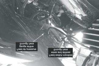
2 Figure 1 Note the routing of airlines and the T fittings Step 2 - Compressor installation The following steps outline the installation of the compressor assembly in the space available directly under the battery box. NOTE: ON MODELS WITH THE EMISSIONS CANISTER IN THIS LOCATION, YOU WILL NEED TO RELOCATED THE CANISTER. NOTE: YOU MUST SLIGHTLY MODIFY THE BATTERY BOX DRAIN TABS PRIOR TO MOUNTING THE COMPRESSOR IN THIS LOCATION. SEE BELOW. NOTE: ON MODELS WITHOUT CRUISE CONTROL. SEE OPTIONAL MOUNTING LOCATION INSTRUCTIONS BEGINNING ON PAGE 4 Battery Box Modification Modify the two battery box drain tabs (with arrows) by placing the Battery Box upside down over a block of wood. Using a plastic mallet, hit the indicated tabs, bending them down so that they are only 1/16 above the bottom surface of the Battery Box. (See figures 2& 2A) Figure 2 Figure 2A Page 2

.")

3 1. Following the procedures in an authorized shop manual for your model, Remove the battery and battery box. 2. Place the compressor and mount assembly into the space above the swingarm and below the space normally occupied by the battery box. See figure 3 3. Re-install the modified battery box through the right side opening and loosely attach top mounting bolts. Installation Under Battery Box 4. Using the hardware supplied with the compressor kit and the OEM rear fender bolt, Attach the compressor mounting bracket to the bottom of the battery box(figure 4). Install the OEM rear fender bolt through the fender, discard the threaded clip nut, through the battery box and tread it into the compressor mounting hole provided. Tighten bolts. (Figure 5) 5. With the compressor mounting bracket securely fastened to the battery box, run both the orange and the black wire up through the left front opening of the battery box. 6. Feed the three airlines attached to the compressor to the right side of the bike. Take the Black line and the Blue line from the silver check valves and route them along the right side of the rear fender up to the T fittings installed previously. To insure sufficient line lengths and clearances for all lines and fittings, it is recommended that you wait until the entire system has been connected before trimming these airlines and making the final connections to the T fittings. The Black line coming from the White T-Fitting will be used to connect to the Pressure Gauge later. Figure 3 Figure 4 7. Tighten the battery box mounting bolts according to your authorized shop manual. Continue with Switch Manifold Installation section on page 5. Figure 5 Page 3


4 Optional Installation for Models without Cruise Control To use this optional Installation, first you must remove the Battery Box Mounting Bracket (A) from the compressor assembly. Do this by removing the two Button Head Socket Screws shown in Figure 6 Be sure to keep the shorter of the two screws, you will need it for mounting the compressor unit in the next step. Continue with #1 Below. Figure 6 Step 2 - Compressor installation 1. Disconnect and remove battery as per manual. 2. Remove saddlebags and left side cover. 3. Use existing holes in battery tray, the short screw removed above and supplied washer to mount compressor unit. Figure 7 4. Torque mounting bolt to 6 ft. lbs. Page 4


5 5. Feed the bottoming control airline, ride height airline and wires though the existing hole in battery box. Figure 8 6. Next run each line to its own, new T fitting. Using the second valve of each T fitting, run airlines to the first set of T fittings that you connected to the shocks in Step 1.5. Figure 9 Figure 10 Step3 Switchmanifold installation Switch Manifold Page 5


6 1. Using the pre-wired switch manifold, nut and bolt supplied, install the manifold to the frame plate located behind the rear rocker box on the left side of bike. Figure Before you tighten the nut on the switch manifold, insert the airlines into valves on the back of switch manifold. The top valve is for the Bottoming Control airline, and the lower valve is for the Ride Height airline (see Figure 10). 3. Route the airlines and wires through the pre-existing hole found in the frame plate, next to mounting hole. Run airlines and wires through this hole and up to battery tray area. 4. There should be two open valves (one on each) on your second set of T fittings. Connect airlines appropriately (making sure all Bottoming Control airlines run through the same T fitting and that all Ride Height airlines do likewise) Figure At this point all airlines should be connected appropriately. It is vital to the operation of the system that there are no crossed lines. We suggest double checking that all airlines are inserted into the correct T fittings. 6. The next few steps will take you through the wiring of the system. Refer to figure 13 and wiring diagram for clarification. All wiring except final connection to battery can be done with the battery uninstalled. Page 6

7 Figure There are three wire leads coming from the switch manifold, red, orange and black. 8. Connect the red wire from the switch manifold to the orange wire with 15 amp fuse in-line. 9. Connect the orange wire from the switch manifold to the orange wire coming from the compressor. 10. Connect the black wire from the switch manifold to the skinny black wire with female connector from the solenoid. 11. Take the other skinny black wire with the male connector from the solenoid and the black wire from the compressor and connect these two wires to the 2 into 1 all black wire. 12. Now with all connections complete,remove the 15 amp fuse from the orange wire. Reinstall the battery and connect that orange wire to battery positive. Connect the 2 into 1 black wire to battery negative. 13. Upon inserting 15 amp fuse back into orange wire, system will be hot and connected properly.pressing the rocker switch in the up direction will activate the compressor to fill the Bottoming Control chamber, and down will activate it to fill the Ride Height chamber. 14. We recommend bundling all extra wire, wrapping in electrical tape or shrink wrap and tucking away from heat and sharp edges. Step 4 Air pressure gauge installation 1. On right side of bike remove two rear top rocker box bolts from the rear cylinder. It may be necessary to loosen and raise/move the fuel tank for clearance when removing bolts. Page 7
, through the frame plate, and insert it into air pressure gauge inlet. (See.")
8 Figure Mount air pressure gauge using empty rocker box holes and stock bolts. Torque as specified in shop manual, not to forget any possible loose bolts in fuel tank. 3. Route the Black airline from the White t-fitting (set aside earlier), through the frame plate, and insert it into air pressure gauge inlet. (See. photo supplement) Note: Air pressure gauge is designed to slowly leak back down to 0 psi. This does not leak any air from the rest of your system. Only air from within the air pressure gauge is leaking out. 4. Once your Airtail I.A.S. system is installed and functioning properly, it is recommended to trim and secure any airlines or wiring. Making sure to avoid pinching, bending at extreme angles, heat and moving or sharp parts. See I.A.S. Setup Instructions. Page 8
9 Photo Supplement Page 9
10 Page 10
Progressive Suspension Airtail I.A.S.
 5572 Fresca Drive, La Palma, CA 90623 714.523.8700, FAX 714.523.3220 Progressive Suspension Airtail I.A.S. Installation Instructions for Harley Davidson E.C.C. with Compressor Kit FLH/FLT Models with and
Installation Instructions Compressor Kit Harley Davidson Dyna Glide Important Notice
 Installation Instructions Compressor Kit Harley Davidson Dyna Glide 91-07 ATTENTION Statements in these instructions that are preceded by the following words are of special significance: W a r n i n g
E.C.C. Airtail Compressor Kit for Airtail Suspension System Installation Instructions
 E.C.C. Airtail Compressor Kit for Airtail Suspension System Installation Instructions The following document will cover Installation Instructions for the following applications: 2000-2006 Harley Davidson
416 Air Shocks For Harley Davidson FLH/FLT 97-later*.
 Installation Instructions ATTENTION Statements in these instructions that are preceded by the following words are of special significance: W a r n i n g This means there is the possibility of injury to
Be sure to refer to instruction supplements provided in any included mounting hardware. Installation Instructions 412CRZ Series Rear Shocks
 Installation Instructions 412CRZ Series Rear Shocks ATTENTION Statements in these instructions that are preceded by the following words are of special significance: W a r n i n g This means there is the
E.C.C. and AirTail Compressor Kit For the Airtail Suspension System Setup Instructions
 E.C.C. and AirTail Compressor Kit For the Airtail Suspension System Setup Instructions Note: Please read and follow the Installation Instructions first, then read and follow these Setup Instructions completely
Installation. Installation Instructions Monotube Cartridge Fork Kit 97-Later* Harley Davidson FLH/FLT
 Installation Instructions Monotube Cartridge Fork Kit 97-Later* Harley Davidson FLH/FLT ATTENTION Statements in these instructions that are preceded by the following words are of special significance:
KIT # MC-2911, MC-2923 FOR ALL YEAR SUZUKI M-109R SERIES
 Congratulations on your purchase of an Arnott Motorcycle Air Suspension system. This system provides you with the ability to maintain your bike at a constant level regardless of load, resulting in enhanced
w w w. h d o n l i n e s h o p. d e CRUISE CONTROL KIT GENERAL INSTALLATION -J04064 REV Kit Number Models Additional Parts Required
 -J006 REV. 006-08- CRUISE CONTROL KIT GENERAL Kit Number 7796-07 Models For the most up-to-date model fitment information, please see the product label or www.harley-davidson.com. Additional Parts Required.
INSTALLATION PROCESS: FK003D945-7 Complete Front, Rear, and Clutch A.B.S. KIT Harley Davidson FLH Touring Models
 INSTALLATION PROCESS: FK003D945-7 Complete Front, Rear, and Clutch A.B.S. KIT 2014-2017 Harley Davidson FLH Touring Models Parts List: 4 Lines 1 Brake Light Switch Adapter 7 Single banjo bolts 2 Caliper
KIT # MC-2992, MC-2993 INDIAN SCOUT SERIES W/ ABS 2014-PRESENT
 Congratulations on your purchase of an Arnott Motorcycle Air Suspension system. This system provides you with the ability to maintain your bike at a constant level regardless of load, resulting in enhanced
SPORTSTER SADDLEBAG KIT. i i02212
 General These saddlebags are designed to fit 99 and later Sportster Model Motorcycles, except XL00 Sport models with gas reservoir shock absorbers and 88R models. See the Service Parts pages for a list
KIT # MC-2990, MC-2991 INDIAN SCOUT SERIES W/O ABS 2014-PRESENT
 Congratulations on your purchase of an Arnott Motorcycle Air Suspension system. This system provides you with the ability to maintain your bike at a constant level regardless of load, resulting in enhanced
RUN/BRAKE/TURN AUXILIARY LIGHTS J
 RUN/BRAKE/TURN AUXILIARY LIGHTS J06236 2018-05-31 GENERAL Kit Numbers 67800589A, 69202276 Models For model fitment information, see the P&A retail catalog or the Parts and Accessories section of www.harleydavidson.com
Page 1. File: Motolight caliper one-piece Harley Date: 8/15/2006
 Page 1 Harley-Davidson FL Caliper Mount Installation One-piece mounting brackets You should allow about two to three hours for installation. We suggest you use a well-lighted space for installation. PLEASE
Kit INSTALLATION GUIDE. 5 psi Low Pressure Sensor (Single Gauge)
") ª Kit 25592 5 psi Low Pressure Sensor (Single Gauge) MN-333 (131107) ECR 7119 INSTALLATION GUIDE For maximum effectiveness and safety, please read these instructions completely before proceeding with installation.
ª Kit 25592 5 psi Low Pressure Sensor (Single Gauge) MN-333 (131107) ECR 7119 INSTALLATION GUIDE For maximum effectiveness and safety, please read these instructions completely before proceeding with installation.
Multistrada (MTS) Tank Installation Notes. Tools Required. Phase 1: Remove Fairings. Phase 2: Remove Fuel Tank
 Tank Installation Notes. Tools Required. Phase 1: Remove Fairings. Phase 2: Remove Fuel Tank") The California Cycleworks MTS tank provides an aftermarket alternative to the OEM nylon fuel tanks as used on aircooled Desmodue Ducati Multistrada 1100, 1000, and 620 models. This fuel tank is NOT for
The California Cycleworks MTS tank provides an aftermarket alternative to the OEM nylon fuel tanks as used on aircooled Desmodue Ducati Multistrada 1100, 1000, and 620 models. This fuel tank is NOT for
Instant Chat off the main page of Or simply call our tech team at
 FRONT MOUNT INTERCOOLER 2015+ WRX 2017-07-07 Thank you for purchasing this PERRIN product for your car! Installation of this product should only be performed by persons experienced with installation of
w w w. h d o n l i n e s h o p. d e ROAD TECH QUEST GLOBAL POSITIONING SYSTEM (GPS) MOUNTING KIT GENERAL INSTALLATION -J03554 REV.
 MOUNTING KIT GENERAL INSTALLATION -J03554 REV.") -J03554 REV. 007-08-0 ROAD TECH QUEST GLOBAL POSITIONING SYSTEM (GPS) MOUNTING KIT GENERAL Kit Number 900-05 Models For model fitment information, please see the P&A Retail Catalog or the Parts and Accessories
-J03554 REV. 007-08-0 ROAD TECH QUEST GLOBAL POSITIONING SYSTEM (GPS) MOUNTING KIT GENERAL Kit Number 900-05 Models For model fitment information, please see the P&A Retail Catalog or the Parts and Accessories
Kit psi Low Pressure Sensor (Dual Gauge)
") ª Kit 25812 5 psi Low Pressure Sensor (Dual Gauge) MN-337 (111107) ECR 7119 INSTALLATION GUIDE For maximum effectiveness and safety, please read these instructions completely before proceeding with installation.
ª Kit 25812 5 psi Low Pressure Sensor (Dual Gauge) MN-337 (111107) ECR 7119 INSTALLATION GUIDE For maximum effectiveness and safety, please read these instructions completely before proceeding with installation.
HP10134 & HP10135 KITS BASIC SIMULTANEOUS AIR SPRING ACTIVATION KIT
 HP10134 & HP10135 KITS BASIC SIMULTANEOUS AIR SPRING ACTIVATION KIT Thank you and congratulations on the purchase of a Pacbrake simultaneous air spring activation kit. This kit was designed to add in-cab
WOC & WOC Top & Back Installation Instructions
 Shown with optional Sun Roof WOC-900500-2 & WOC-900501-2 Top & Back Installation Instructions Install Order! Heater Door System Wiper on to Windshield Windshield Rear Panel Top Panel Tools needed: 5/16
INSTALLATION LIGHTED CURVED LAY DOWN LICENSE PLATE MOUNT 3166
 INSTALLATION LIGHTED CURVED LAY DOWN LICENSE PLATE MOUNT 3166 PARTS INCLUDED 1 Lighted Curved Lay Down License Plate Assembly 1 Hardware Kit Including: 6 Cable Ties 1 Dielectric Grease Pack 1 1 x 8 Tape
PRODUCT SAFETY NOTICE
 PRODUCT SAFETY NOTICE Congratulations. This vehicle has been equipped with a Firestone air suspension system. This suspension will enhance the vehicle s handling when loaded, however, the vehicle s performance
Part # C-10 Level 1 Air Suspension System
 350 S. St. Charles St. Jasper, In. 47546 Part # 11330199 63-72 C-10 Level 1 Air Suspension System Front Components: 1 11331099 Front CoolRide Kit for Stock Lower Arms 1 11330509 RQ Series Front Shock Kit
R4TECH PRODUCT SAFETY NOTICE
 R4TECH PRODUCT SAFETY NOTICE Congratulations. This vehicle has been equipped with an R4Tech suspension system that provides the ride quality of a full-air suspension with the ease of installation of a
KIT # MC-3104 FOR HARLEY DAVIDSON DYNA SERIES
 Congratulations on your purchase of an Arnott Motorcycle Air Suspension system. This system provides you with the ability to maintain your bike at a constant level regardless of load, resulting in enhanced
Engine Management System
 Engine Management System 6 0 4-0 0 1 I N S T R U C T I O N S For 2005-2010 Harley-Davidson FXS (Softail) Models 2 Revolution Performance was founded with two major goals in mind to go that extra mile providing
w w w. h d o n l i n e s h o p. d e ELECTRA-GLO LIGHT BARS GENERAL INSTALLATION -J04723 REV Kit Number Models Kit Contents
 -J07 REV. 00-0-0 GENERAL Kit Number -09 Models For model fitment information, see the P&A Retail Catalog or the Parts and Accessories section of www.harley-davidson.com (English only). Kit Contents See
GL1800 TRAILER HITCH - INSTALLATION INSTRUCTIONS #GL
 GL1800 TRAILER HITCH - INSTALLATION INSTRUCTIONS #GL18007-20 Read through these instructions completely before attempting installation, lay out all pieces including the numbered hardware bags to familiarize
Page 1. File: Motolight caliper one-piece Date: 8/14/2006
 Page 1 Caliper Mount Installation One-piece mounting brackets You should allow about two to three hours for installation. We suggest you use a well-lighted space for installation. PLEASE READ ALL THE INSTRUCTIONS.
w w w. h d o n l i n e s h o p. d e HEATED HAND GRIP KITS GENERAL REMOVAL -J02983 REV Kit Number Models Kit numbers Service Parts
 -J098 REV. 007-0-0 GENERAL Kit Number 56047-0B, 5607-0B, 5674-0B, 5696-0B, 565-0B, 5669-0A, 56694-04A, 56750-04A, 5688-0A, 569-05, 5696-05, 56997-07 Models For model fitment information, please see the
INSTALLATION INSTRUCTIONS FOR THE TOMAHAWK ELECTRIC REVERSE
 INSTALLATION INSTRUCTIONS FOR THE TOMAHAWK ELECTRIC REVERSE LAST UPDATED: April 2018 Thank you for choosing the Motor Trike Electric Reverse. We ask that you read the directions before you start and follow
2010+ Victory Cross Country / Cross Roads Installation Guide Nov 2014
 2010+ Victory Cross Country / Cross Roads Installation Guide Nov 2014 125 Industrial Drive Spearfish, SD 57783 Toll Free 888.3WHEELS w w w. l e h m a n t r i k e s. c o m UNDERSTANDING SAFETY LABELS &
INSTALLATION INSTRUCTIONS
 INSTALLATION INSTRUCTIONS Part # 751-FP2500 IMPORTANT INFORMATION This Jagg oil cooler must be installed following these instructions. Read the easy-to-follow instructions fully prior to starting the installation
HP10207 KIT. Ram WD*
 HP10207 KIT Ram 1500 4WD* (For 2WD call customer service 800.663.0096 for assistance) * See application guide for proper fitment. Use the most advanced air springs on the market to eliminate your vehicle
Installation Procedure GR40 S197 SLA Front Suspension System (Does not include Aluminum Spindle and Hub Instructions)
") Installation Procedure GR40 S197 SLA Front Suspension System (Does not include Aluminum Spindle and Hub Instructions) Please take the time and read these instructions first! The GR40 S197 system is designed
Installation Procedure GR40 S197 SLA Front Suspension System (Does not include Aluminum Spindle and Hub Instructions) Please take the time and read these instructions first! The GR40 S197 system is designed
ONBOARD AIR HOOKUP KIT
 ONBOARD AIR HOOKUP KIT PART NO. 20052 (30 amp - 110PSI on, 150PSI off) PART NO. 20053 (30 amp - 85PSI on, 105 PSI off) PART NO. 20055 (30 amp - 90 PSI on, 120 PSI off) IMPORTANT: It is essential that you
Installation Instructions
 Installation Instructions Jeep JK 2-Door (2011 Present) Mounting Bracket and Air Line System Kit for ARB On-Board Twin Air Compressor (CKMTA12) Made in the USA Kit Contents: 1 Flat Bracket 1 Formed Bracket
w w w. h d o n l i n e s h o p. d e LAYBACK LICENSE PLATE AND TURN SIGNAL RELOCATION KIT INSTALLATION GENERAL -J03892 REV Kit Number
 -J0 REV. 00-0-0 LAYBACK LICENSE PLATE AND TURN SIGNAL RELOCATION KIT GENERAL Kit Number 0-0 Models For model fitment information, please see the P&A Retail Catalog or the Parts and Accessories section
INSTALLATION PROCESS: FK003D932-6 FRONT & REAR A.B.S. KIT 2017 Harley Davidson FXDL Lowrider S ABS
 INSTALLATION PROCESS: FK003D932-6 FRONT & REAR A.B.S. KIT 2017 Harley Davidson FXDL Lowrider S ABS Parts List: 6 Lines 1 Splitter Block 4 A.B.S. Block Bolts (KIT A) 1 1x1/4 x20x1 Bolt 4 Caliper/Front Master
w w w. h d o n l i n e s h o p. d e ROAD KING FAT HANDLEBAR KIT GENERAL PREPARATION - ALL MODELS -J02375 REV Kit Number Models ABS Models
 -J02375 REV. 2008--9 GENERAL Kit Number 56675-05 Models For model fitment information, see the P&A Retail Catalog or the Parts and Accessories section of www.harley-davidson.com (English only). ABS Models
DYNA OIL COOLER AND THERMOSTAT KIT
 INSTRUCTIONS -J000 REV. 07-5-00 Kit Numbers 6985-0 (Chrome) and 6989-0 (Silver) General DYNA OIL COOLER AND THERMOSTAT KIT These oil cooler kits feature a thermostat built-in to the oil filter mount. These
MODEL NUMBER: MEDIUM DUTY ONBOARD AIR SYSTEM
 MODEL NUMBER: 10003 MEDIUM DUTY ONBOARD AIR SYSTEM IMPORTANT: It is essential that you and any other operator of this product read and understand the contents of this manual before installing and using
Instructions on installing the R/R to the front battery cover.
 April, 2008 Instructions on installing the R/R to the front battery cover. Please read all of the steps so you will be familiar with the complete relocation installation first. The purpose of this relocation
INSTALLATION INSTRUCTIONS Toyota FJ Cruiser DEMELLO-OFFROAD.
 INSTALLATION INSTRUCTIONS Item Description Vehicle 3 piece Rear Bumper 2007-2014 Toyota FJ Cruiser DEMELLO-OFFROAD www.demello-offroad.com 12785 magnolia ave Riverside ca 92503 Suite 1 phone: 1-951-735-4417
2017+ L5P Duramax 3 ½ Down Pipe & EGR Fix Kit
 2017+ L5P Duramax 3 ½ Down Pipe & EGR Fix Kit Covers installation of PN s: WCF100630, WCF100829 Note: This Kit is for off road competition use only! Off Road Competition Use Tuning & Exhaust System is
1 M-3000-H4 F150 4X4 Lowering Kit
 READ INSTRUCTIONS COMPLETELY THROUGH BEFORE STARTING. IT IS RECOMMENDED THAT INSTALLATION BE DONE BY A QUALIFIED MECHANIC. REPLACE ALL STOCK PARTS THAT ARE DAMAGED OR WORN. ALWAYS WEAR EYE PROTECTION.
"Engineered to Ride, Built to Last "
 Congratulations on your purchase of an Arnott air suspension product. We at Arnott Incorporated are proud to offer a high quality product at the industry s most competitive pricing. Thank you for your
RT1 SLIP-ON EXHAUST HONDA CBR600RR REV. A
 08-50-43733 REV. A PARTS INCLUDED Ref. Part Number Description Qty 1) 00-200-00064 Slip-on S-bend Assembly 1 2) 00-200-00088 RT1 Aluminum Muffler Assembly 1 3) 03-46-43058 Muffler Mounting Strap 1 4) 07-27-42566
OIL COOLER KIT INSTALLATION INSTRUCTIONS PART NUMBER D
 OIL COOLER KIT INSTALLATION INSTRUCTIONS PART NUMBER D570-0904 APPLICATION: 2011-2012 E90 335i/xi (N55 engine) with BMW standard bumper and with stock oil cooler Congratulations for being selective enough
Application(s) > Items Supplied > Instruction Manual >
 > Items Supplied > Instruction Manual >") 301 E. La Palma Ave., Yorba Linda, Ca 97 Ph. 714.69.10, Fax. 714.69.5016 Items Supplied > Application(s) > www.fi000r.com 1 Fi000R Fuel Injection Module Zip Ties 1 Velcro Strip Oxygen Sensor Eliminators
301 E. La Palma Ave., Yorba Linda, Ca 97 Ph. 714.69.10, Fax. 714.69.5016 Items Supplied > Application(s) > www.fi000r.com 1 Fi000R Fuel Injection Module Zip Ties 1 Velcro Strip Oxygen Sensor Eliminators
INSTALLATION INSTRUCTIONS Air Spring Kit IMPORTANT NOTES
 INSTALLATION INSTRUCTIONS 6119 Air Spring Kit Thank you for purchasing a quality Hellwig Product. PLEASE READ THIS INSTRUCTION SHEET COMPLETELY BEFORE STARTING YOUR INSTALLATION IMPORTANT NOTES DO NOT
PRODUCT SAFETY NOTICE DEALER/INSTALLER NOTICE
 PRODUCT SAFETY NOTICE Congratulations. This vehicle has been equipped with a Firestone air suspension system. This suspension will enhance the vehicle s handling when loaded, however, the vehicle s performance
TEARDROP SPECIFIC-FIT
 TEARDROP SPECIFIC-FIT SADDLEBAGS 3501-0461 3501-0462 FEATURES OF THE SADDLEMEN SADDLEBAGS: Quality luggage system that adds style and function to your motorcycle Bag shape and mounts specially built to
ONBOARD AIR SYSTEM FOR ALL VEHICLES APPLICATIONS
 ONBOARD SYSTEM FOR ALL VEHICLES APPLICATIONS Thank you and congratulations on the purchase of a Pacbrake onboard air system. Please read the manual prior to starting to ensure you can complete the installation
GSX-R1000 EXHAUST KIT
 GSX-R1000 EXHAUST KIT (UNDERTAIL EXHAUST KITS AVAILABLE IN BLACK, WHITE OR SILVER) CAREFULLY READ ALL INSTRUCTIONS BEFORE BEGINNING THE INSTALLATION PROCESS! AS WITH ANY PERFORMANCE MODIFICATION, YOU SHOULD
INSTALLATION INSTRUCTIONS
 Rear Vision System Tailgate Emblem Camera Mirror Display 2009-Current Ford F-150 and 2010-Current Super Duty (Kit part number 1008-9527) Kit Contents: Mirror Tailgate Emblem Mount with Camera Interior
WRX/STI Engine Oil Cooler
 2002-14 WRX/STI Engine Oil Cooler 2014-04-21 Thank you for purchasing this PERRIN product for your car! Installation of this product should only be performed by persons experienced with installation of
Assembly Instructions
 Assembly Instructions Part Number Description Model Approx. Assembly Time 99994-0903 Windshield Wiper Kit Mule SX 1 Hour WARNING Improper installation of this accessory could result in an accident causing
9th Gen Honda Civic INSTALLATION GUIDE Civic, Civic Si Kit Civic Si Kit Front Application
 9th Gen Honda Civic 2012-15 Civic, 2012-13 Civic Si Kit 78526 2014+ Civic Si Kit 78556 Front Application INSTALLATION GUIDE For maximum effectiveness and safety, please read these instructions completely
05 12 TOYOTA TACOMA 2WD
 MAXTRAC SUSPENSION 4030 E LEAVERTON CT ANAHEIM, CA 92807 714 630 0363 WWW.MAXTRACSUSPENSION.COM SALES@MAXTRACSUSPENSION.COM PRODUCT: PARTS LIST K756864 6" LIFT KIT 05 12 TOYOTA TACOMA 2WD QTY SPINDLE,
INSTALLATION INSTRUCTIONS
 INSTALLATION INSTRUCTIONS Part# 22-7810 Add On Kit for Your ADS System Contents: Complete Install Kit for Your ARB CKMTA12V Compressor For the most up-to-date instructions please visit www.updownair.com
STaSIS Engineering B6 B7 Streetsport Suspension
 STaSIS Engineering B6 B7 Streetsport Suspension SS Suspension Kit Parts List Qty Description Part Number 1 STaSIS adjusted Koni cadmium plated dampers (2 front, 2 rear) 1150-5061 Special Tools Required
MAZDA BT-50 (October 2011 Production Onwards) 1 & 3 PIECE HARD TONNEAU REMOTE LOCKING KIT INSTALLATION INSTRUCTIONS
 1 & 3 PIECE HARD TONNEAU REMOTE LOCKING KIT INSTALLATION INSTRUCTIONS") MAZDA BT-50 (October 0 Production Onwards) & 3 PIECE HARD TONNEAU REMOTE LOCKING KIT INSTALLATION INSTRUCTIONS Installation Time: Approx. 0 Minutes Care Instructions: Clean Tonneau Cover with a mild detergent
MAZDA BT-50 (October 0 Production Onwards) & 3 PIECE HARD TONNEAU REMOTE LOCKING KIT INSTALLATION INSTRUCTIONS Installation Time: Approx. 0 Minutes Care Instructions: Clean Tonneau Cover with a mild detergent
A. Preparing the charge harness. Start by removing the plastic covers by the battery terminal.
 twist battery relocate kit and harness. Step 1 A. Remove battery. Start by removing the negative battery cable and then the positive. After removing the battery cables remove the battery hold down bracket.
HP10220 KIT. See application guide for proper fitment.
 HP10220 KIT Dodge Dakota* (2WD/4WD) * 2005 All Dodge Dakotas 2006 - All Dodge Dakotas except Night Runner and R/T sub models 2007 - All Dodge Dakotas except SXT and TRX4 sub models 2008 - All Dodge Dakotas
IAG Street Series Air / Oil Separator (AOS) For WRX
 For WRX") P IAG Street Series Air / Oil Separator (AOS) For 2015-16 WRX Part# IAG-ENG-7152 Tools Required: Ratchet, torque wrench, extensions, needle nose pliers, hose cutter, snips/scissors, flat head screw driver,
P IAG Street Series Air / Oil Separator (AOS) For 2015-16 WRX Part# IAG-ENG-7152 Tools Required: Ratchet, torque wrench, extensions, needle nose pliers, hose cutter, snips/scissors, flat head screw driver,
INSTALLATION INSTRUCTIONS FUEL RAIL
 INSTALLATION INSTRUCTIONS FUEL RAIL MITSUBISHI EVO X Document# 19-0067 Support: info@radiumauto.com WARNING: DON'T SMOKE OR WORK WITH OPEN SPARKS WHILE WORKING ON THE FUEL SYSTEM PREPARING THE VEHICLE:
SADDLEBAG AUDIO WIRE HARNESS KIT P/N
 SADDLEBAG AUDIO WIRE HARNESS KIT P/N 2880986 APPLICATION ALL INDIAN MOTORCYCLES WITH BOTH TRUNK AND SADDLEBAG AUDIO INSTALLED BEFORE YOU BEGIN Read these instructions and check to be sure all parts and
OIL COOLER KIT INSTALLATION INSTRUCTIONS PART NUMBER D E92 335i/xi (N55 engine) with BMW Standard bumper and with stock oil cooler
 with BMW Standard bumper and with stock oil cooler") OIL COOLER KIT INSTALLATION INSTRUCTIONS PART NUMBER D570-0924 APPLICATION: 2011-12 E92 335i/xi (N55 engine) with BMW Standard bumper and with stock oil cooler Congratulations for being selective enough
OIL COOLER KIT INSTALLATION INSTRUCTIONS PART NUMBER D570-0924 APPLICATION: 2011-12 E92 335i/xi (N55 engine) with BMW Standard bumper and with stock oil cooler Congratulations for being selective enough
Line Lock Package, Mustang GT/GT500, 2007 PACKING LIST
 PART #M25002 Line Lock Package, Mustang GT/GT500, 2007 PACKING LIST Before installation, use this check list to make sure all necessary parts have been included. ITEM QTY CHECK PART NUMBER DESCRIPTION
1200 Southeast Ave Tallmadge, Ohio to 2014 Mustang (V6 & V8) Summit Racing Roll Stop Install Instructions.
 Summit Racing Roll Stop Install Instructions.") 1200 Southeast Ave Tallmadge, Ohio 44278 2010 to 2014 Mustang (V6 & V8) Summit Racing Roll Stop Install Instructions Part # SUM-760005 Thank you for considering the Summit Racing Roll Stop. Summit Racing
1200 Southeast Ave Tallmadge, Ohio 44278 2010 to 2014 Mustang (V6 & V8) Summit Racing Roll Stop Install Instructions Part # SUM-760005 Thank you for considering the Summit Racing Roll Stop. Summit Racing
INSTALLATION FORK MOUNTED DRIVING LIGHTS 5008
 5008 PARTS INCLUDED 1 Right Fork Mount Assembly 1 Left Fork Mount Assembly 2 H3 Driving Light Assemblies 1 12-Pin Wiring Adapter 1 Hardware Kit for Fork Mount Driving Lights, Including: 6 5/16-18 Nylock
Installation Instructions for the F2B Pedal Bracket Kit
 Installation Instructions for the F2B Pedal Bracket Kit A. General Information 1. Before you begin, familiarize yourself with this installation procedure. It is assumed that the installer is an experienced
Trike Conversion Installation Guide for Harley-Davidson Sportster Motorcycles 2004 & Up Revision 7
 Trike Conversion Installation Guide for Harley-Davidson Sportster Motorcycles 2004 & Up Revision 7 CAUTION : Failure to follow these instructions can lead to serious personal injury and/or property damage
Mustang Shaker
 2005-2009 Mustang Shaker CDC #110050 ( 05/ 06) or 0711-7000-01 ( 07/ 09) Component Check List: Quantity/Description Part # CDC Installer 1 - Engine Cover Assembly 114050 1 - Aluminum Shaker Scoop 183020
Ford Mustang V6 OEM-Style Fog Light Kit Parts List: Quantity: Tool List:
 2015-2017 Ford Mustang V6 OEM-Style Fog Light Kit Parts List: Quantity: Tool List: LED Foglights/ Bezels 2 Flat head & Phillips screwdriver (if you ordered part#3600) Ratchet & Socket set OR Wiring harness
Installation Instructions Harley-Davidson Saddlebag Lids
 Installation Instructions Harley-Davidson Saddlebag Lids Thank you for your purchase of Bagger Audio Saddlebag Lids for your Harley- Davidson motorcycle. We have carefully engineered these products to
 Page 1 of 9 Home Account Contact ALLDATA Log Out Help DAN GRIMWOOD DAN GRIMWOOD00002 Select Vehicle New TSBs Technician's Reference Component Search: OK 1985 Dodge Truck D 350 Pickup V8-360 5.9L VIN I
Included parts: 1 - New Bosch CP3 Pump 1 - HSM Pulley 1 - Serpentine Belt 1 - Pump Bracket/ Hardware STEP 1
 TROUBLESHOOTING: Please read and understand all installation instructions before proceeding with the installation. If you have questions during the installation of this product, please contact H&S Motorsports
Remove black panel shown. Save 6 retaining pins for re-install later. Pry up on center part of pin first. Then pry out entire retaining pin.
 2005-2009 Ford Mustang V6 Fog Light Wiring Kit Parts List: Quantity: Tools Required: Wiring harness 1 Flat head screwdriver Supplemental wire leads 2 Ratchet & Socket set OR Wire tap red 2 Adjustable Wrench
REV 200SG Kit-RM. High Performance Front Speaker Kit with 200 Watt Amplifier. installation Manual
 REV 200SG Kit-RM High Performance Front Speaker Kit with 200 Watt Amplifier For Use Use On On 1998-2013 rushmore Ultra Classics platform And Tri-Glides models installation Manual Thank you for choosing
LGT-306L / LB Club Car Precedent LED Light Bar Bumper Kit Installation Instructions
 LGT-306L / LB Club Car Precedent LED Light Bar Bumper Kit Installation Instructions Caution: Please read through the instructions carefully. Before starting this project, remove the system s positive and
07 & UP GM 1500 PICKUP 2.0 FRONT 1.0 REAR LEVELING KIT INSTALLATION
 INSTRUCTION PART NO 15265 LEVELING KIT NO 3813 07 & UP GM 1500 PICKUP 2.0 FRONT 1.0 REAR LEVELING KIT INSTALLATION READ INSTRUCTIONS/WARNINGS COMPLETELY THROUGH BEFORE STARTING. FAILURE TO ADHERE TO THE
AEV30308AA Last Updated: 05/31/18. 4 DUALSPORT sc SUSPENSION system for RAM 1500 air ride standard and rebel INSTALLATION GUIDE
 AEV30308AA Last Updated: 05/31/18 4 DUALSPORT sc SUSPENSION system for RAM 1500 air ride standard and rebel INSTALLATION GUIDE PLEASE READ BEFORE YOU START TO GUARANTEE A QUALITY INSTALLATION, WE RECOMMEND
Fig A. Addictive Desert Designs. Preparation: Removal:
 Preparation: Disconnect the negative battery terminal. Park the vehicle on level ground and set the emergency brake. We recommend reading through the installation instructions in whole before performing
#TL T EA888 GEN 3 FUELING SYSTEM/ INSTALLATION INSTRUCTIONS
 #TL100069 2.0T EA888 GEN 3 FUELING SYSTEM/ INSTALLATION INSTRUCTIONS Notes: These instructions were written for a North American specification MkVII GTI. Other models, like the Golf R, are similar. When
IAG Competition Series Air / Oil Separator (AOS) For WRX
 For WRX") P IAG Competition Series Air / Oil Separator (AOS) For 2015-16 WRX Part# IAG-ENG-7252 Tools Required: Ratchet, torque wrench, extensions, needle nose pliers, hose cutter, snips/scissors, flat head screw
P IAG Competition Series Air / Oil Separator (AOS) For 2015-16 WRX Part# IAG-ENG-7252 Tools Required: Ratchet, torque wrench, extensions, needle nose pliers, hose cutter, snips/scissors, flat head screw
N-084M and N-069M-DV Series Heat Exchanger Replacement
 N-084M and N-069M-DV Series Heat Exchanger Replacement Models Include: N-069M-DV, N-084M, N-084M-DV N-084M-ASME, N-084M-DV-ASME This instructional manual is only intended for use by a qualified service
INSTALLATION INSTRUCTIONS Auto Level Compressor Kit IMPORTANT NOTES
 INSTALLATION INSTRUCTIONS 4880 Auto Level Compressor Kit Thank you for purchasing a quality Hellwig Product. PLEASE READ THIS INSTRUCTION SHEET COMPLETELY BEFORE STARTING YOUR INSTALLATION IMPORTANT NOTES
Z1 Motorsports 370Z/G37 Oil Cooler Kit Installation Manual
 Z1 Motorsports 2877 Carrollton Villa Rica Hwy Carrollton GA 30116 770.838.7777 Z1 Motorsports 370Z/G37 Oil Cooler Kit Installation Manual For 19, 25 and 34 Row Oil Cooler Kits Parts Included: 1 SETRAB
INSTALLATION INSTRUCTIONS BILLET FUEL RAIL KIT
 INSTALLATION INSTRUCTIONS BILLET FUEL RAIL KIT MITSUBISHI LANCER EVOLUTION X Document# 19-0067 Support: info@radiumauto.com WARNING: DON'T SMOKE OR WORK WITH OPEN SPARKS WHILE WORKING ON THE FUEL SYSTEM
***THE OWNER'S MANUAL MUST BE GIVEN TO THE END USE CUSTOMER AFTER COMPLETING THE INSTALLATION.***
 INSTALLATION INSTRUCTIONS FOR THE MOTOR TRIKE HARLEY MECHANICAL REVERSE 1999-2006 FIVE SPEED FLH LAST UPDATED: OCTOBER 2011 AS THE INSTALLER OF THIS MECHANICAL REVERSE, YOU MUST BECOME FAMILIAR WITH PROPER
150 PSI ILLUMINATED DASH PANEL GAUGE KIT
 150 PSI ILLUMINATED DASH PANEL GAUGE KIT PART NO. 10061 (For Use with 20/30 Amp Systems) PART NO. 20062 (For Use with 30/40 Amp Systems) IMPORTANT: It is essential that you and any other operator of this
Thermo-Bob 1 Installation Manual: Kawasaki Concours
 Thermo-Bob 1 Installation Manual: 1986-2006 Kawasaki Concours This is a basic guide for installing the Thermo-Bob 1 on a Kawasaki ZG-1000 Concours. The bike used in the following photos was a 1995 year
3 October 2016 PN# V Dodge Twin Turbo Kit (I-00274) ½ D o d g e 2 4 v I S B
 ½ D o d g e 2 4 v I S B") 3 October 2016 PN#1045320 24V Dodge Twin Turbo Kit (I-00274) 1 DOWNLOAD ENHANCED INSTALL MANUALS AT dieselperformance.com BD Twin Turbo Kit 1998½- 2 0 0 2 D o d g e 2 4 v I S B Part# 1045320 PLEASE READ
3 October 2016 PN#1045320 24V Dodge Twin Turbo Kit (I-00274) 1 DOWNLOAD ENHANCED INSTALL MANUALS AT dieselperformance.com BD Twin Turbo Kit 1998½- 2 0 0 2 D o d g e 2 4 v I S B Part# 1045320 PLEASE READ
HP10033 KIT. * See application guide for proper fitment.
 HP10033 KIT * See application guide for proper fitment. Use the most advanced air springs on the market to eliminate your vehicle s sag, sway and bottoming out. Pacbrake air suspension levels your truck
Installation Instructions
 Instructions Created by an: 2005+ Toyota Tacoma BTB Front Coilovers by Low Range Off Road SKU# TAC-SP-05CO-BTB-650 Diff Drop Kit (SKU# LR-2GDDK) Instructions included Installation Instructions Revised
'99-03 CHEVROLET/GMC IFS 4WD 6" SUSPENSION SYSTEM P/N INSTALLATION INSTRUCTIONS
 1/16/04 '99-03 CHEVROLET/GMC IFS 4WD 6" SUSPENSION SYSTEM P/N. 10-41099 INSTALLATION INSTRUCTIONS NOTE: Each Lift Kit and options to Lift Kits are packaged separately. Therefore, installation procedures