N-084M and N-069M-DV Series Heat Exchanger Replacement
|
|
|
- Antony Summers
- 6 years ago
- Views:
Transcription
1 N-084M and N-069M-DV Series Heat Exchanger Replacement Models Include: N-069M-DV, N-084M, N-084M-DV N-084M-ASME, N-084M-DV-ASME This instructional manual is only intended for use by a qualified service professional or authorized Noritz Service Representative. Any unauthorized use of this manual may result in voiding the warranty. Please contact Noritz Technical Support ( ) for additional support. Noritz America Corporation Grace Avenue, Fountain Valley, CA Phone Fax Page 1
2 N-084M(-DV), N-084M(-DV)-ASME, and N-069M-DV Heat Exchanger Replacement Procedure Procedure 1. Remove front cover (1) Disconnect electrical power to unit (2) Remove 4 screws (3) Turn off gas and water (4) Remove filter and drain unit completely 2. Remove the Manifold Plate and Gas Pipe (1) Remove the 4 large silver screws around the edge of the manifold plate (2) Remove the black set screw that holds the gas pipe into the bottom of the plate (3) Remove the wiring to the solenoids that are on the manifold plate. (4) Locate inlet gas pipe. There is a black set screw on the bottom of this pipe that holds it on to the gas valve. Remove this screw and pull the pipe straight out. Page 2
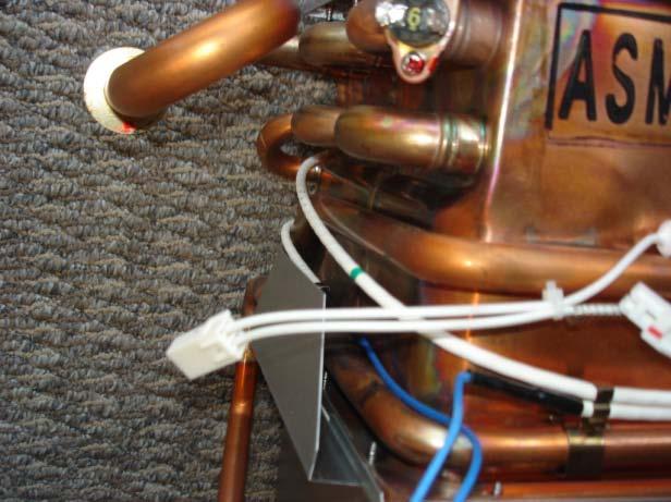
 The bypass flow control valve is to the left of the heat exchanger.")
3 3. Remove the bypass pipe (1) The bypass flow sensor is in the bottom center of the heater. Remove the C clamp on the bottom of the flow sensor and the C clamp on the front. Pull the pipe out of the front of the flow sensor then pull the flow sensor up and out. (2) The bypass flow control valve is to the left of the heat exchanger. Remove the C clamp from the back of the flow control valve. (3) Remove the pipe (4) Disconnect the wiring from the bypass flow control valve Page 3
4 4. Disconnect the water pipes coming from the heat exchanger. (1) Locate the main flow control valve in the upper left corner of the heater and the main flow sensor that is located to the left of the burner. (2) Remove C clamps from flow sensor and main flow control valve (3) Disconnect water pipes from each water connection 5. Remove any wiring that is attached to the burner and heat exchanger (1) Remove the wiring for the igniter, flame rod, and burner sensor on the front of the burner. The blue wire and black wire can be disconnected from the front of the burner; the middle/white wire has to be followed into the wiring harness and disconnected there (it becomes a red/white wire then a white plug). Page 4
5 (2) Remove the two white clips that connect the frost sensing switch on the upper left corner of the heat exchanger. (3) Remove the black and white wires from the igniter. (4) Remove the high limit switch on the upper right side of the heat exchanger by removing the screw. (5) Disconnect the wiring for the thermal fuse (white wire that wraps around heat exchanger, the connectors are blue). (6) Disconnect the wiring to the fan motor (5 multicolored wires). Page 5
6 6. Remove heat exchanger from case (1) Remove the 4 screws on the top of the case around the exhaust vent. (2) Remove the 3 set screws on the bottom of the burner (on the left and right sides of the fan housing) (3) Remove the upper left and right set screws near the top center of the case (support bottom of assembly) (4) The heat exchanger, burner, and fan will now slide forward and drop down. The drop allows the venting to slide through the opening in the top of the heater. Page 6

7 7. Separate burner from heat exchanger (1) Remove 14 screws holding burner to heat exchanger. (2) The exhaust box will have to be removed there are 14 screws. A gasket is supplied with the heat exchanger for between the heat exchanger and exhaust box 8. Remove thermal fuse and freeze prevention heater and reattach to new heat exchanger (1) From the front left of the burner, the route of the thermal fuse is across the front, then up when going along the right side of the HX, then across the back high, then bring it back down to the front, then make the entire second wrap of the heat exchanger low. Caution: The thermal fuse is a fusible link encased in a protective covering. If it is subjected to sharp bends or pinched it could break and have to be replaced. Page 7


8 FRONT SIDE RIGHT SIDE LEFT SIDE Page 8
 Place the heat exchanger onto the burner.")
.")

9 9. Replace burner gasket (1) Remove old gasket (2) Replace with new gasket 10. Reattach burner and HX (1) Place the heat exchanger onto the burner. It is usually best to stand the heat exchanger upside down and let the burner rest on top. Verify the orientation of the heat exchanger and burner (see picture). As well, there are two L-shaped plates that attach on the left and right of the burner; these plates are fastened using the front two screws on each side. (2) Replace the exhaust box with 14 screws, there will be a gasket that comes with the new heat exchanger Page 9
 Replace the 2 set screws")


10 11. Replace the heat exchanger (1) Set the heat exchanger, burner, and fan assembly in place (2) Replace the 2 set screws on the top of the burner box and the 3 short screws on the side of the fan. (3) Replace the plates on the top of the heater. The larger plate goes on the bottom, then the gray/foam gasket between the two plates, then put the smaller plate on top. Page 10
 Reconnect the thermal fuse wires.")
 Replace the two white clips that connect the frost sensing switch on the upper left corner of the heat exchanger.")
11 12. Replacing wiring that is attached to the burner and heat exchanger (1) Reconnect the wiring to the fan motor. (2) Reconnect the thermal fuse wires. (3) Replace the wiring for the igniter, flame rod, and burner sensor on the front of the burner. (4) Replace the two white clips that connect the frost sensing switch on the upper left corner of the heat exchanger. (5) Replace the black and white wires from the igniter. (6) Replace the high limit switch on the upper right side of the heat exchanger. Page 11
12 13. Reconnect the water pipes coming from the heat exchanger. (1) Replace the water pipes on the main flow control valve and flow sensor. (2) Replace the C clamps on the main flow sensor and valve. The C clamp on the main flow control valve is one of the larger rounded off clamps. The C clamp on the flow sensor is large on one side, small on the other (see picture). Note how the pipe is pushed completely into the elbow and the C clamp is clipped over the pipe not on the fitting. 14. Replace the bypass pipe (1) Put the pipe back in place (2) Push the bypass flow control valve back into place. Reconnect the C clamp on the back of the flow control valve. (3) Reconnect the wiring to the bypass flow control valve Page 12
. 15.")
13 (4) Replace the bypass flow sensor. Put the flow sensor in place and push it down onto the inlet fitting first then reconnect the C clamp (this C clamp is larger and is rounded off). Then push the pipe into the front of the flow sensor and reconnect the C clamp (This C clamp is smaller than the C clamp on the bottom, squared off, and labeled 12.7). 15. Replace the gas pipe (1) Push the gas pipe into the gas valve then replace the black set screw. (2) Replace the clips onto the solenoids. Notice that the clips are numbered the numbers will match up to numbers printed on the manifold plate. Page 13
 Replace the 4 large silver screws.")
14 16. Replace the Manifold Plate (1) Replace the gas pipe into the bottom of the manifold plate. Make sure the pipe is pushed in fully then replace the black set screw. This screw should tighten down to the head if the thread is still visible on the screw, the gas pipe is not fully replaced and could leak. (2) Replace the 4 large silver screws. Do this with a screwdriver as the screws will strip if too much torque is applied 17. Replace the front cover (1) Replace filter (2) Turn on gas and water (slowly, check for leaks from C clamps) (3) Replace the 4 front cover screws (4) Restore electrical power Page 14
Heater Parts. LXi Low NOx. See Detail on next page Zodiac Pool Systems, Inc. Product Catalog. Heater Parts. After. July Before.
 LXi Low NOx 47 23 After July 2009 23 65 48 33 28 65 50 49 Before July 2009 22 26 Detail 22 63 64 25 67 25 9 62 33 27 6 34 35 62 4 36 2 32 20 57 60 8 72 58 59 7 52 56 4 54 53 7 68 70 69 90 55 6 See Detail
Interior Tankless Models
 GAS REPLACEMENT PARTS LIST Interior Tankless Models TG-15OI-(N,X) TG-180I-(N,X) TG199I-(N,X) TG-237I-(N,X)(A) Effective: May, 2013 ECO 7853 NOTE: BOTH MODEL AND SERIAL NUMBERS ARE REQUIRED FOR ORDERING
Legacy Combustion Chamber Replacement Kit
 H0324700- Replacement Kit Instructions WARNING FOR YOUR SAFETY - This product must be installed and serviced by authorized personnel, qualifi ed in pool/spa heater installation. Improper installation and/or
2015+ SUBARU STI FRONT-MOUNT INTERCOOLER PARTS LIST AND INSTALLATION GUIDE INSTALL DIFFICULTY DISCLAIMER CAUTION INSTALL PROCEDURE TOOLS NEEDED
 PARTS LIST AND PARTS INCLUDED 1PC ALUMINUM INTAKE PIPE 1PC BAR-AND-PLATE INTERCOOLER 1PC STEEL CRASH BAR W/ MOUNTING HARDWARE 2PC HOT-SIDE INTERCOOLER PIPES 2PC COLD-SIDE INTERCOOLER PIPES 1PC BPV FLANGE
External outfitting NRC661-DV 001 B
 External outfitting NRC661-DV 021 017 020 020 018 016 040 A 001 B 074 003 002 025 014 C D 012 013 036 027 041 011 019 003 002 External outfitting NRC661-OD 043 040 022 001 132 025 B E D C 074 002 012 080
Do not have any open flame or heat sources close to the installation
 March 6, 2017 IS# 791 Page 1 of 16 Thank you for purchasing a Transfer Flow, Inc. 50-gallon replacement fuel system for your 2011-16 Ford diesel short bed pickup. This system will fit any 2x4 or 4x4 crew
INSTALLATION INSTRUCTIONS
 AUTOMOTIVE PRODUCTS, INC. INSTALLATION INSTRUCTIONS ULTIMATE BULL BAR APPLICATION: 2017 Ford F-250/350 PART NUMBER: 32-3900, 32-3905, 32-3900L, 32-3905L ITEM QUANTITY DESCRIPTION TOOLS NEEDED 1 1 ULTIMATE
Multistrada (MTS) Tank Installation Notes. Tools Required. Phase 1: Remove Fairings. Phase 2: Remove Fuel Tank
 Tank Installation Notes. Tools Required. Phase 1: Remove Fairings. Phase 2: Remove Fuel Tank") The California Cycleworks MTS tank provides an aftermarket alternative to the OEM nylon fuel tanks as used on aircooled Desmodue Ducati Multistrada 1100, 1000, and 620 models. This fuel tank is NOT for
The California Cycleworks MTS tank provides an aftermarket alternative to the OEM nylon fuel tanks as used on aircooled Desmodue Ducati Multistrada 1100, 1000, and 620 models. This fuel tank is NOT for
Airtail I.A.S. Suspension System for Harley Davidson
 5572 Fresca Drive, La Palma, CA 90623 714.523.8700, FAX 714.523.3220 Airtail I.A.S. Suspension System for Harley Davidson Compressor Kit Installation Instructions FLH/FLT Models with and without Cruise
1996 Aerostar/Ranger/Explorer
 Page 1 of 11 Section 03-01B: Engine, 3.0L V-6 IN-VEHICLE SERVICE 1996 Aerostar and Ranger Vehicles Workshop Manual Water Pump SPECIAL SERVICE TOOL(S) REQUIRED Description Tool Number Fan Clutch Holding
Cooling system components, removing and installing
 Page 1 of 40 19-1 Cooling system components, removing and installing WARNING! The cooling system is pressurized when the engine is warm. When opening the expansion tank, wear gloves and other appropriate
INSTALLATION INSTRUCTIONS AIR/OIL SEPARATOR KIT
 INSTALLATION INSTRUCTIONS AIR/OIL SEPARATOR KIT 2015+ SUBARU WRX (LHD ONLY) Document: 19-0136 Support: info@radiumauto.com This document covers the installation of the Radium brake master cylinder brace
BEFORE BEGINNING INSTALLATION
 COMPLETE CHASSIS FUEL LINE KITS For 1996-2000 Honda Civic Equipped with B-Series Engine INSTALLATION INSTRUCTIONS PLEASE study these instructions carefully before beginning this installation. Most installations
FUEL PUMP SYSTEM CIRCUIT
 EG190 FUEL PUMP SYSTEM CIRCUIT ONVEHICLE INSPECTION 1. CHECK FUEL PUMP OPERATION (a) Using SST, connect terminals +B and FP of the DLC1. SST 0984318020 (b) Turn the ignition switch ON. NOTICE: Do not start
GAS CONVERSION KIT INSTALLATION INSTRUCTIONS
 GAS CONVERSION KIT INSTALLATION INSTRUCTIONS These instructions apply to the following gas conversion kits: 8261139 8261140 8261141 8261142 8261143 8261144 8261158 8261747 8261748 8261964 8261965 8263059
Installation Instructions for: TOYOTA 4.5L SUPERCHARGER SYSTEM
 Installation Instructions for: TOYOTA 4.5L SUPERCHARGER SYSTEM 1995-1997 Land Cruiser * PREMIUM FUEL REQUIRED * Magnuson Products LLC 1990 Knoll Drive, Bldg A, Ventura, CA 93003 (805) 642-8833 phone *
Jeep Wrangler TJ. Complete Air Conditioning System. Slide Control Head. Installation instructions
 WWW.JEEPAIR.COM 1996-1998 Jeep Wrangler TJ Complete Air Conditioning System Slide Control Head Installation instructions Kit Information After 1994 every vehicle was designed for R134a refrigerant. The
FUEL PUMP SYSTEM CIRCUIT
 EG1182 22RE ENGINE FUEL PUMP SYSTEM CIRCUIT ONVEHICLE INSPECTION 1. CHECK FUEL PUMP OPERATION (a) Turn the ignition switch ON. HINT: Do not start the engine. (b) Using SST, connect terminals Fp and +B
PAGE 1. TES Operation & Testing Guidelines: Tes Trouble shooting
 PAGE 1 This document outlines questions to ask and components to check during TES troubleshooting. More detailed troubleshooting procedures are available in the TES Troubleshooting Guide. 1. Flow Light
FlowMax Lift Pump Kit
 15 June 2016 (1050316) 2008-2010 Ford 6.4L FlowMax Lift Pump Kit (I-00359) - 1-2008-2010 Ford 6.4L PowerStroke FlowMax Lift Pump Kit Installation Instructions P/N# 1050316 PLEASE READ ALL INSTRUCTIONS
Energysaver 559FT. Rinnai New Zealand Limited Page 1 of 6 Rinnai Energysaver 559FT Spare Parts: 01-11
 039 017 028 012 019 037 020 018 038 026 701 013 038 027 804 012 Top panel 1 5485 013 Control panel assembly 1 5486 016 Side panel RH 1 5488 017 Side panel LH 1 5489 018 Air filter assembly 1 3026 019 Front
AIR CLEANER GENERAL REMOVAL. 1CAUTION Do not run engine without filter element in place. Debris could be drawn into the engine causing damage.
 AIR CLEANER GENERAL The air cleaner prevents foreign material from entering the carburetor and engine by trapping airborne dust and dirt in the filter element. Service air cleaner filter element every
Q35 Series Automatic Vent Damper System
 Installation Sheets Manual 121 Energy Conservation and Miscellaneous Kits Section Q Technical Bulletin Q35 Issue Date 0999 Q35 Series Automatic Vent Damper System Figure 1: Q35 Automatic Vent Damper System
3.4L V6 SUPERCHARGER 7 TH INJECTOR KIT
 Part Number: 00602-17620-260 00602-17620-261 00602-17620-263 00602-17620-264 00602-17620-274 00602-17620-275 00602-17620-276 Section I Installation Preparation Kit Contents Item # Quantity Reqd. Description
INSTALLATION INSTRUCTIONS
 INSTALLATION INSTRUCTIONS HDX LED GRILLE APPLICATION: 06-07 Toyota Tacoma PART NUMBER: 34-065 ITEM QUANTITY DESCRIPTION TOOLS NEEDED HDX GRILLE 0MM SOCKET 8 M6 HEX NUT (YELLOW ZINC) 3 8 M6 SPLIT LOCK WASHER
SLP Camaro ZL1 STAGE 3 (650 HP)
") SLP - 2012 Camaro ZL1 STAGE 3 (650 HP) PART #26002 PACKING LIST Before installation, use this check list to make sure all necessary parts have been included. ITEM QTY CHECK PART NUMBER DESCRIPTION 1. 1
SLP - 2012 Camaro ZL1 STAGE 3 (650 HP) PART #26002 PACKING LIST Before installation, use this check list to make sure all necessary parts have been included. ITEM QTY CHECK PART NUMBER DESCRIPTION 1. 1
FUEL PUMP SYSTEM CIRCUIT
 EG199 FUEL PUMP SYSTEM CIRCUIT ONVEHICLE INSPECTION 1. CHECK FUEL PUMP OPERATION (a) Using SSt, connect terminals +B and FP of the data link connector 1. SST 0984318020 (b) Turn the ignition switch ON.
Turner M50 Manifold Adapter Install. April 26, 2012
 April 26, 2012 Models: 1996-99 E36 328i/M3; 1997-98 E39 528i, 1997-98 Z3 2.8, 1998-2000 MZ3 S52 Product(s): Turner M50 Manifold Adapter Kit Subject: Installation Guidelines and Tips This guide will aid
Ford 6.0L. Part #: Part #: BD GASKET PART# will be needed for this installation.
 1 BD EGR COOLER 2003-2007 Ford 6.0L Part #: 1090201 Part #: 1090202 PLEASE READ ALL INSTRUCTIONS BEFORE INSTALLATION BD GASKET PART# 1090002 will be needed for this installation. 2 K I T C O N T E N T
Hydraulic Oil Cooler. Assembly Instructions (Originating w/serial Number )
") Hydraulic Oil Cooler Case 465 Skid Steer Assembly Instructions (Originating w/serial Number 50-101) Model Number: Serial Number: Date of Purchase: Specialized Equipment, Inc. 650 So. Main Street - PO Box
Hydraulic Oil Cooler Case 465 Skid Steer Assembly Instructions (Originating w/serial Number 50-101) Model Number: Serial Number: Date of Purchase: Specialized Equipment, Inc. 650 So. Main Street - PO Box
Adding Additional Gripper Circuits (SG3 & SG4)
") 1.) Turn On your robot and sign into your designated Level of Access 2.) Go into Function>>>Function Set>>>Advanced>>>Output List 3.) On the first page of the Output List, on the far-right column, there
1.) Turn On your robot and sign into your designated Level of Access 2.) Go into Function>>>Function Set>>>Advanced>>>Output List 3.) On the first page of the Output List, on the far-right column, there
Included parts: 1 - BorgWarner SX-E Turbocharger 1 - SX-E 90-Degree Compressor Outlet Elbow 1 - HSM Cast Exhaust Manifold 1 - HSM Downpipe
 TROUBLESHOOTING: Please read and understand all installation instructions before proceeding with the installation. If you have questions during the installation of this product, please email H&S Motorsports
1080 CF Valve Replacement Instructions
 Overview This kit includes the newer American Flame gas control valve designed specifically for the 1080 CF gas fireplace. If you have a 1080 CF fireplace, and you are uncertain as to whether this kit
2017+ L5P Duramax 3 ½ Down Pipe & EGR Fix Kit
 2017+ L5P Duramax 3 ½ Down Pipe & EGR Fix Kit Covers installation of PN s: WCF100630, WCF100829 Note: This Kit is for off road competition use only! Off Road Competition Use Tuning & Exhaust System is
DESCRIPTION MECHANICAL FUEL PUMP FUEL FILTER HIGH PRESSURE (35-90 PSI) HIGH PRESSURE (35-90 PSI) (STEEL/INCLUDED)
 HIGH PRESSURE (35-90 PSI) (STEEL/INCLUDED)") Edelbrock EFI Universal Fuel Sump System - Adjustable Part #36031, 36032, 36033, 36034 INSTALLATION INSTRUCTIONS PLEASE study these instructions carefully before beginning this installation. This installation
Edelbrock EFI Universal Fuel Sump System - Adjustable Part #36031, 36032, 36033, 36034 INSTALLATION INSTRUCTIONS PLEASE study these instructions carefully before beginning this installation. This installation
JODALE PERRY. Parts List & Mounting Instructions. Jacobsen HR9016 JDP BUILT FOR LIFE
 JODALE PERRY Parts List & Mounting Instructions Jacobsen HR9016 JDP BUILT FOR LIFE Jacobsen HR9016 Mounting Instructions Standard Parts 1 - LH Rear Mounting Bracket 1 - RH Rear Mounting Bracket 1 - Front
Edelbrock EFI Universal Fuel Sump System - Adjustable Part #36031, INSTALLATION INSTRUCTIONS
 Edelbrock EFI Universal Fuel Sump System - Adjustable Part #36031, 36032 INSTALLATION INSTRUCTIONS PLEASE study these instructions carefully before beginning this installation. This installation can be
Installation Notes for Ford Excursion 7.3L
 The following document is used in conjunction with the puradyn Bypass Oil Filtration System Installation Manual (PFT 8) that is included in the unit box, and as such, should be considered a supplemental
Aftertreatment System December Removal of the 1-BOX from the Vehicle. Installation of the 1- BOX to the Vehicle
 12 13-18 1 12 13-18 SUBJECT DATE Aftertreatment System December 2018 Additions, Revisions, or Updates Publication Number / Title Platform Section Title Change Removal of the 1-BOX from the Vehicle Installation
Phone Fax
 Directions for Installation of ECS Paxton Supercharger Kit Disconnect battery Remove stock serpentine belt Remove stock belt tensioner, save the 2 bolts for later use on supercharger bracket Remove alternator
Installation Notes for Asplundh Chipper Model- 1003ASP- (EPS) Kubota 3.3 L KIT DOC
 Kubota 3.3 L KIT DOC") Note: Even though a banjo fitting has been provided, some engines have been known to have different size drain plugs, requiring a different size banjo fitting. If the banjo fitting provided does not match
Note: Even though a banjo fitting has been provided, some engines have been known to have different size drain plugs, requiring a different size banjo fitting. If the banjo fitting provided does not match
Adding Additional Vacuum Circuits
 1.) Turn On your robot and sign into your designated Level of Access 2.) Go into Function>>>Function Set>>>Advanced>>>Output List 3.) On the first page of the Output List, on the far right column, there
Fuel Pickup Kit ( ) Installation Guide
 Installation Guide") Pacific Performance Engineering, Inc. PPEdiesel.com 2001-2005 Fuel Pickup Kit (113051000) Installation Guide Technical Support (714) 985-4825 Rev: 12/02/2016 v7 * Note: LEGAL IN CALIFORNIA ONLY FOR RACING
Pacific Performance Engineering, Inc. PPEdiesel.com 2001-2005 Fuel Pickup Kit (113051000) Installation Guide Technical Support (714) 985-4825 Rev: 12/02/2016 v7 * Note: LEGAL IN CALIFORNIA ONLY FOR RACING
SECTION 1D2 M161 ENGINE COOLING
 SECTION 1D2 M161 ENGINE COOLING CAUTION: Disconnect the negative battery cable before removing or installing any electrical unit or when a tool or equipment could easily come in contact with exposed electrical
These instructions were written for reference only and the use of a factory service manual is recommended.
 Introducing the CorkSport High Pressure Fuel Line designed for the MZR DISI. This fuel line is designed to replace the OEM fuel line which are prone to failure at the brazed connection at the rail. The
Routine Burner Service
 Routine Burner Service WARNING Rural Energy Enterprises, Inc. does not accept liability for the improper use of this information. Installation, service, and maintenance of heating equipment should be performed
Conf licts Note: TOYOTA Tacoma 2016 LED Illumination Package (Interior and Exterior) Part Number: Accessory Code: LL1000.
 Part Number: Accessory Code: LL1000.") TOYOTA Tacoma 2016 LED Illumination Package (Interior and Exterior) Part Number: 00016-00069 Accessory Code: LL1000 Conf licts Note: Color Applicability/Trim Level Kit Contents Item # Quantity R eqd. Description
TOYOTA Tacoma 2016 LED Illumination Package (Interior and Exterior) Part Number: 00016-00069 Accessory Code: LL1000 Conf licts Note: Color Applicability/Trim Level Kit Contents Item # Quantity R eqd. Description
Revision THERMO TECHNOLOGIES. USDT 2001 Differential Controller. Installation and User s Guide
 Revision 8 THERMO TECHNOLOGIES USDT 2001 Differential Controller Installation and User s Guide USDT 2001 DIFFERENTIAL CONTROLLER Installation and User s Guide Table of Contents Introduction General Information
Includes: 1. Upgraded Tube Type EGR Cooler 2. Silicone Hoses
 Includes: 1. Upgraded Tube Type EGR Cooler 2. Silicone Hoses CAUTION: Never work on a hot vehicle. The hot exhaust system or hot engine can cause serious injury in the form of burns. If the vehicle has
Intake Manifold Replacement
 Page 1 of 14 2004 Chevrolet TrailBlazer - 4WD Bravada, Envoy, Rainier, TrailBlazer (VIN S/T) Service Manual Engine Engine Mechanical - 4.8L, 5.3L, and 6.0L Repair Instructions - On Vehicle Document ID:
RAYPAK REPLACEMENT PARTS
 POOL MODELS: R185B THROUGH R405B CATALOG NO. 9100.555 Effective: 03-01-17 Replaces: 10-15-14 RAYPAK REPLACEMENT PARTS MODEL SIZES: R185B, R265B, R335B, R405B (ATMOSPHERIC, LOW NOx) MODEL TYPES: RP2100
Shotgun Single Barrel HPFP install guide
 Shotgun Single Barrel HPFP install guide Thank you for your purchase of the VTT Shotgun Single Barrel HPFP upgrade! First thing to do when you open your box is to make sure all parts are in their respective
Jeep Wrangler TJ 4.0 LITER Installation instructions
 www.jeepair.com 2000-2001 Jeep Wrangler TJ 4.0 LITER Installation instructions Important information about your system, and warranty DO NOT ADD ANY OIL TO ANY PART OF THE SYSTEM. DO NOT USE THE SIGHT GLASS
Installation manual BMW E TS1/TS2
 Installation manual BMW E46 330 TS1/TS2 Technical support Europe: +4741558555 Technical support USA: (858)314-2954 Email support: support@esstuning Installation manual BMW E46 330 TS1/TS2 Remove and send
All cores due 30 days after invoice date - no credit after 60 days.
 NO WARRANTY STATEMENT High performance parts & products no warranty policy: The purchaser understands and recognizes that high performance diesel products and services sold by INDUSTRIAL INJECTION SERVICE.
These instructions were written for reference only and the use of a factory service manual is recommended.
 Introducing the CorkSport High Pressure Fuel Line designed for the MZR DISI. This fuel line is designed to replace the OEM fuel line which are prone to failure at the brazed connection at the rail. The
INSTALLATION INSTRUCTIONS
 INSTALLATION INSTRUCTIONS HDX LED GRILLE APPLICATION: 013-017 Dodge Ram 1500 PART NUMBER: 34-1035 ITEM QUANTITY DESCRIPTION TOOLS NEEDED 1 1 HDX LED GRILLE 10MM SOCKET,3 UPPER BRACKET A, DRIVER () AND
255 Liter/Hr, In Tank Fuel Pump For Chrysler Front Wheel Drive Vehicles Catalog # INSTALLATION INSTRUCTIONS
 255 Liter/Hr, In Tank Fuel Pump For 1984-1990 Chrysler Front Wheel Drive Vehicles Catalog # 17934 INSTALLATION INSTRUCTIONS PLEASE study these instructions carefully before installing your new In-Tank
v2.0 Qube Engineering 2010 LED Gauge Cluster DIY Supplemental Instructions AP2_1.x v2.0 Page 1
 Qube Engineering 21914 Palos Verdes Blvd Torrance, CA 90503 818-271-QUBE (7823) art@qube-engineering.com v2.0 Qube Engineering 2010 LED Gauge Cluster DIY Supplemental Instructions AP2_1.x v2.0 Page 1 Qube
UNIVERSAL PUMP HANGER INSTALLATION INSTRUCTIONS
 UNIVERSAL PUMP HANGER INSTALLATION INSTRUCTIONS WARNING! THESE INSTRUCTIONS MUST BE READ AND FULLY UNDERSTOOD BEFORE BEGINNING INSTALLATION. FAILURE TO FOLLOW THESE INSTRUCTIONS MAY RESULT IN POOR PERFORMANCE,
TECHNICAL INSTRUCTIONS
 TECHNICAL INSTRUCTIONS 24 Month Maintenance Kit Instructions For Benchmark 2500-3000 Boilers Maintenance Kit # 58025-10 Flame Detector P/N 66034 Ignitor- Injector P/N 58023 Exhaust Manifold Seal P/N 84040
2009 Buick Truck Enclave AWD V6-3.6L
 ALLDATA Repair - 2009 Buick Truck Enclave AWD V6-3.6L - Service and Repair Page 1 of 10 2009 Buick Truck Enclave AWD V6-3.6L Vehicle» Powertrain Management» Fuel Delivery and Air Induction» Fuel Tank Unit»
1501 Industrial Way N., Toms River, NJ Fax: PACKING LIST MUSTANG GT LONG TUBE HEADERS (M30000)
") ADVANCED - Installation requires professional-type tools and advanced automotive-service skills. If you lack experience with internal engine modifications, an Advanced installation is probably beyond your
ADVANCED - Installation requires professional-type tools and advanced automotive-service skills. If you lack experience with internal engine modifications, an Advanced installation is probably beyond your
Includes: 1. Silicone Hose 2. EGR Block Off Plates 1. Exhaust Block Off Plate 2. Hose Clamps 1. Spacer/Washer 8. Bolts 2. Nuts
 Includes: 1. Silicone Hose 2. EGR Block Off Plates 1. Exhaust Block Off Plate 2. Hose Clamps 1. Spacer/Washer 8. Bolts 2. Nuts WARNING: This product is not legal for sale or use on pollution controlled
M-9424-M50CJ INTAKE MANIFOLD INSTALLATION INSTRUCTIONS
 Please visit www.fordracingparts.com for the most current instruction information!!! PLEASE READ ALL OF THE FOLLOWING INSTRUCTIONS CAREFULLY PRIOR TO INSTALLATION. AT ANY TIME YOU DO NOT UNDERSTAND THE
Fuel Pickup Kit GM 6.6L Duramax ( )
") PPEdiesel.com GM 6.6L Duramax 2006-2008 (113052000) Installation Guide Technical Support (714) 985-4825 Rev: 06/08/18 v7a Note: LEGAL IN CALIFORNIA ONLY FOR RACING VEHICLES THAT MAY NEVER BE USED, OR REGISTERED
PPEdiesel.com GM 6.6L Duramax 2006-2008 (113052000) Installation Guide Technical Support (714) 985-4825 Rev: 06/08/18 v7a Note: LEGAL IN CALIFORNIA ONLY FOR RACING VEHICLES THAT MAY NEVER BE USED, OR REGISTERED
INSTALLATION INSTRUCTIONS
 HIGH FLOW AIRFLOW METER INSTALLATION INSTRUCTIONS PART NUMBER D763-1600A APPLICATION: 2001-06 E46 M3 Parts List: Hose clamp 64Z (7) Plastic Rivets Air Filter Temp Sensor & Harness (2) Button Head Screws
INSTRUCTION, HALDEX PUMP LVS KIT P/N
 LIFT CORPORATION Sht. 1 of 11 DSG# M-06-33 Rev. - Date: 12/17/07 INSTRUCTION, HALDEX PUMP LVS KIT P/N 267923-01 MALE BULLET LVS WIRE HARNESS P/N 267924-01 QTY. 1 LOW VOLTAGE SWITCH (LVS MODULE) P/N 906530-01
INSTALLATION INSTRUCTIONS BILLET FUEL RAIL KIT
 INSTALLATION INSTRUCTIONS BILLET FUEL RAIL KIT MITSUBISHI LANCER EVOLUTION X Document# 19-0067 Support: info@radiumauto.com WARNING: DON'T SMOKE OR WORK WITH OPEN SPARKS WHILE WORKING ON THE FUEL SYSTEM
Performance Inlet Manifold
 Performance Inlet Manifold Tools needed (some tools not required on some models): 13mm Combination Wrench Flat Blade Screwdriver T30 Torx Driver T25 Torx Driver 10mm Combination Wrench and/or Socket with
05/03/ INST. Ford 6.0L Aurora Turbo Installation v Ford 6.0L Powerstroke
 Ford 6.0L Aurora Turbo Installation v1.6 2003-2007 Ford 6.0L Powerstroke Please read all instructions before installation. 1. Begin by disconnecting the negative terminals of both batteries. 2. Find the
Single Barrel Shotgun HPFP Install Guide
 Single Barrel Shotgun HPFP Install Guide Thank you for purchasing the VTT Single Barrel Shotgun HPFP upgrade kit! PLEASE READ THE ENTIRE GUIDE BEFORE BEGINNING INSTALLATION! The first thing you should
Part List: Jandy LXI Series Heaters
 Part List: Jandy LXI Series Heaters Models LXI250, LXI400 For pool heater parts, equipment and any pool accessories, visit www.torontopoolsupplies.ca 1-844-416-7665 416-623-9334 info@torontopoolsupplies.ca
Step 6: Remove and save the MAP sensor for later use. Step 7: Remove the passenger side intercooler pipe and the EGR intake manifold.
 LBZ Twin kit Install Step 1: Disconnect both batteries. Step 2: Drain coolant and oil also remove passenger side inner fender. Step 3: Remove intake box and piping. (Remove and save the MAF sensor in the
Prodigy HDLV System Troubleshooting - Generation III
 Prodigy HDLV System Troubleshooting - Generation III Instruction Sheet P/N 1081071-05 Use the procedures listed in this document to isolate and correct common problems with Prodigy HDLV Systems. Refer
INSTALLATION INSTRUCTIONS
 INSTALLATION INSTRUCTIONS HDX LED GRILLE APPLICATION: 2019 Ram 1500 (Excl. Classic) PART NUMBER: 34-1145 CONTENT ITEM QUANTITY DESCRIPTION TOOLS NEEDED 1 1 GRILLE 10MM WRENCH 2 2 LED LIGHT HOUSING RATCHET
PowerMax Diesel Upgrade For Cummins Engines
 PowerMax Diesel Upgrade For Cummins Engines 00.5-007.5 Dodge Ram With Cummins 5.9L Item 3 4 5 6 7 8 9 0 3 4 5 6 7 8 Parts List Description Turbocharger Ancillary kit 773069- (includes) Installation Instructions
Installation Instructions
 SLP GM/Chevrolet LS3 COIL COVER KIT 2010+ Camaro 5.3L/6.2L 2007+ GMT900 5.3L/6.2L PN: 620038 Installation Instructions Important Notes: Before installing your SLP Coil Cover Kit, please read the installation
Installation Instructions Pro Stick Shifter
 Installation Instructions Pro Stick Shifter Part Number 80701, 80702 & 80706 2012, 2010, 2008, 2001, 1998 by B&M Racing and Performance Products The B&M Pro Stick shifter #80701 and #80706 comes equipped
Front Drive System - Big Block Chevy Installation Instructions Big Block Chevy with AC & with PS
 Front Drive System - Big Block Chevy Installation Instructions Big Block Chevy with AC & with PS All American Billet Store (800) 764-0926 www.allamericanbilletstore.com Items needed for install Jack Jack
MOTOALLIANCE WINCH MOUNT
 , / 1-866-527-7637 www.motoalliance.com MOTOALLIANCE WINCH MOUNT Polaris RZR Thank you for purchasing our MotoAlliance winch mount(s). You now own a premium custom winch mount to allow you to use your
Weistec M113K Supercharger System Installation Guide
 Weistec M113K Supercharger System Installation Guide WARNING! DO NOT HAVE YOUR ECU REPROGRAMMED ANYWHERE BUT AT WEISTEC FOR THIS SUPERCHARGER. THE AMG 55 USES AN ELECTRONIC THROTTLE CONTROL (ETC), WHICH
FUEL PUMP. ON VEHICLE INSPECTION 1. CHECK FUEL PUMP OPERATION (a) Using SST, connect terminals +B and FP of the data link connector 1.
 Using SST, connect terminals +B and FP of the data link connector 1.") EG2250 FUEL PUMP ONVEHICLE INSPECTION 1. CHECK FUEL PUMP OPERATION (a) Using SST, connect terminals +B and FP of the data link connector 1. SST 0984318020 (b) Turn the ignition switch ON. NOTICE: Do not
EG2250 FUEL PUMP ONVEHICLE INSPECTION 1. CHECK FUEL PUMP OPERATION (a) Using SST, connect terminals +B and FP of the data link connector 1. SST 0984318020 (b) Turn the ignition switch ON. NOTICE: Do not
Flex Fuel Bluetooth Kit BRZ / FRS / GT86 install instructions
 Delicious Tuning 1250 Activity Dr. Ste A Vista, CA 92081 408-480-0995 Rev: 1.0 Date: 8/20/18 FFBT parts: (1) Ethanol Content Analyzer Module (1) Ethanol Content Analyzer Sensor (1) Sensor Bracket (1) Velcro
ALL AMERICAN BILLET. Front Drive System - Small Block Ford Installation Instructions
 ALL AMERICAN BILLET Front Drive System - Small Block Ford Installation Instructions Small Block Ford with AC & PS All American Billet Store (800) 764-0926 www.allamericanbilletstore.com Items needed for
SHELBY GT500
 2007-2009 SHELBY GT500 Removal of Factory Unit WARNING: 1. Radiator fluid must be handled properly. Please observe local ordinances with regards to handling and disposal. 2. Allow vehicle and components
Cummins Coolant Bypass Kit:
 Cummins Coolant Bypass Kit: 2003-2007 Automatic Transmissions 8 9 10 Part # Description Quantity 1 Fleece Performance thermostat Housing 1 2 M12 Flange Head Bolts 2 3 OE Thermostat housing Riser Block
Special Note About The JDM High Performance Water Pump:
 Page 1 of 30 JDM Engineering, Inc. home Call Us! 732-780- 0770 back to Installation Instructions Electric Fan Upgrade Kit Electric Fan Wiring Diagram Thank you for your purchase of the JDM Engineering
INSTALLATION INSTRUCTIONS FUEL SURGE TANK KIT
 INSTALLATION INSTRUCTIONS FUEL SURGE TANK KIT BMW E46 3-Series, Excl Convertible Document: 19-0056 Support: info@radiumauto.com Relieve fuel pressure in vehicle before beginingthe installation. Disconnect
KIT CONTENTS. Multimeter or test light Wire crimpers or soldering equipment. Wire terminals & connectors 10A inline fuse
 RUSSELL FORD 5.0L COMPLETE EFI PLUMBING KIT INSTALLATION INSTRUCTIONS Please study these instructions carefully before installing your new complete fuel system kit. If you have any questions, please call
 Page 1 of 9 Home Account Contact ALLDATA Log Out Help DAN GRIMWOOD DAN GRIMWOOD00002 Select Vehicle New TSBs Technician's Reference Component Search: OK 1985 Dodge Truck D 350 Pickup V8-360 5.9L VIN I
UNIVERSAL PUMP HANGER INSTALLATION INSTRUCTIONS
 UNIVERSAL PUMP HANGER INSTALLATION INSTRUCTIONS WARNING! THESE INSTRUCTIONS MUST BE READ AND FULLY UNDERSTOOD BEFORE BEGINNING INSTALLATION. FAILURE TO FOLLOW THESE INSTRUCTIONS MAY RESULT IN POOR PERFORMANCE,
Troubleshooting Guide
 Troubleshooting Guide This guide contains information for identifying and correcting issues that may arise. Applicable Models: i200 i200p i250 i250p i200x i201x i250x i251x iq251 iq251d iq751 iq1001 iq1501
Instant Chat off the main page of Or simply call our tech team at
 FRONT MOUNT INTERCOOLER 2015+ WRX 2017-07-07 Thank you for purchasing this PERRIN product for your car! Installation of this product should only be performed by persons experienced with installation of
INSTALLATION INSTRUCTIONS
 AUTOMOTIVE PRODUCTS, INSTALLATION INSTRUCTIONS ULTIMATE BULL BAR APPLICATION: 2009-2018 Dodge Ram 1500 (Excl. Rebel Model) 2019 Dodge Ram 1500 Classic PART NUMBER: 32-1960, 32-1965, 32-1960L, 32-1965L
Installation Instructions Part Number
 Installation Instructions Part Number 84152143 Thank you for choosing Chevrolet Performance as your high performance source. Chevrolet is committed to providing proven, innovative performance technology
SERVICE MANUAL Model: SF-INS30-BK - Instructions -
 SERVICE MANUAL Model: SF-INS30-BK - Instructions - NOTICE! DO NOT discard any hardware while servicing. It must be reused. This manual will assist a qualified service technician in the replacement of parts.
Switch Base Replacement Instructions 3-Pole, 60 AMP, Fusible, w Neutral, Visible-Blade, Heavy Duty Safety Switches
 Step Switch Base Replacement Instructions 3-Pole, 60 AMP, Fusible, w Neutral, Visible-Blade, Heavy Duty Safety Switches Work Description All work should be performed in accordance with NFPA 70E. Tools
INSTALLATION INSTRUCTIONS
 INSTALLATION INSTRUCTIONS Accessory Application Publications No. BII 24570 P/N 08U97-S3V-210A (BLACK) P/N 08U97-S3V-220A(SADDLE) 2003 MDX Issue Date OCT 2002 PARTS LIST Wood steering wheel 1. Make sure