Table of Contents
|
|
|
- Edwina Green
- 5 years ago
- Views:
Transcription


1 Flexirun Self Repairing Rapid Roll Up Door Quick Assembling Guidebook Flexirun PLC Curtain Unwinding Detection Safety Edge Manualopen Basic or Easy /indupart /indupart /indupart /company/indupart-ltd
2 Table of Contents sales@indupart.co.uk

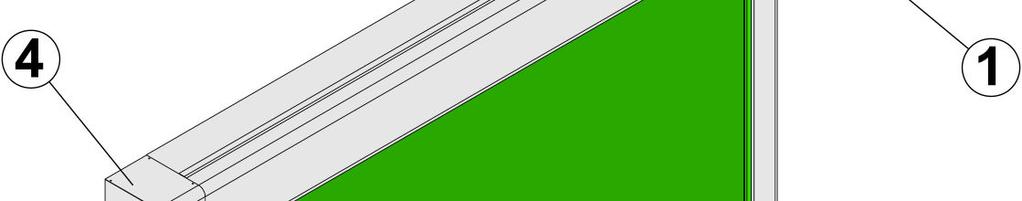


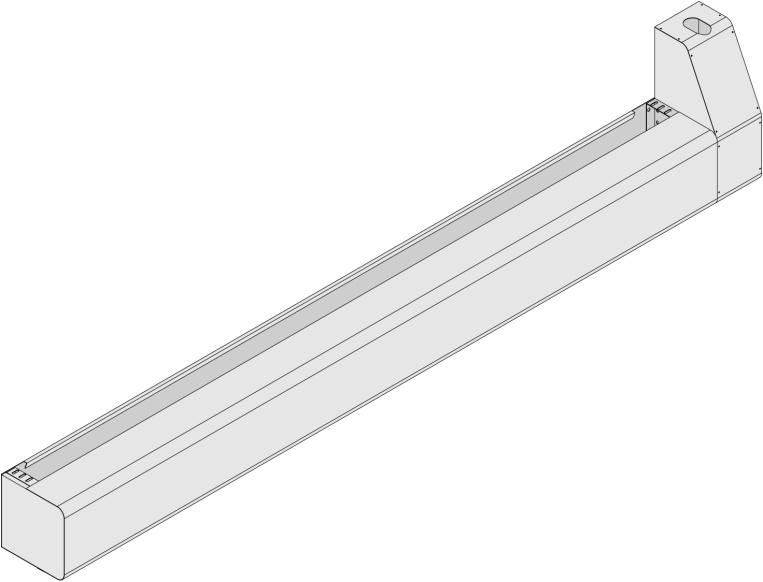
3 Unpacking
4


5
6 (*) Canopy and Columns Assembling Table A sales@indupart.co.uk
7 Canopy and Columns Assembling Table B sales@indupart.co.uk 7


8 Door Lifting sales@indupart.co.uk
9 Wiring Between Control Board and Terminal Board Table A sales@indupart.co.uk 9
10 Wiring Between Control Board and Terminal Board Table B sales@indupart.co.uk
11 General Wiring
. 8. Push button till the door will be closed. 9.")

12 3.Pull guides towards the door center. 4. Insert curtain cogged edges in guides. 5. Pull the curtain edge by hand to 500 mm about under the canopy. 6. Connect the main power supply 7. Find the function SET on the PLC (see following pages). 8. Push button till the door will be closed. 9.Stretch the curtain moving columns towards door sides. 10. The curtain stretching will be correct if the gap between the column frame and the guide will be 5 mm about per door side when the curtain is moving in guides. 11. Fasten bolts on columns beginning from the upper column part. Curtain Stretching sales@indupart.co.uk
13 Limit Switch A sales@indupart.co.uk 13


14 Limit Switch B sales@indupart.co.uk
15 Safety Edge
16 Safety Photocells A sales@indupart.co.uk
17 Safety Photocells B sales@indupart.co.uk 17

18 Motor Connections
19 Motor Safety Switch Connections


20 PLC


21 LED Table
 CLOSING ONLY NO OPENING ONLY NO OPENING PUSH")

22 24 V AC MAX 250 ma 24 V AC MAX 250 ma CURTAIN UNWINDING DETECT. + SAFETY EDGE NC OPENING CONTROLS (RADARS/INDUCTION LOOPS) CLOSING ONLY NO OPENING ONLY NO OPENING PUSH BUTTON PEDESTRIAN OPENING NO COMMON SAFETY PHOTOCELL CONTACT NC COMMON EMERGENCY PUSH BUTTON NC OPEN DOOR LIMIT SWITCH NC OPENING SLOWING DOWN LIMIT SWITCH NC CLOSING SLOWING DOWN LIMIT SWITCH NC PLC Lower Part sales@indupart.co.uk

23 PLC Upper Part
 Closing only NC Opening only NO Opening")
 Control input for opening with closing timer NO : radars,pull cords,induction loops.")
24 SEE THE PAGE CONTROL CARD UPPER PART FLEXIRUN WITH CURTAIN UNWINDING DETECTION AND SAFETY EDGE MANUALOPEN BASIC OR EASY Red Photocells in the canopy Violet (Prewired cable from the terminal board) Connections Controls Safeties Emergencies 24VAC Max 250mA Page 24 0VAC Max 250mA Curtain unwinding detection + safety edge NC Opening with closing timer NO (*) Closing only NC Opening only NO Opening with closing timer NO (**) Pedestrian opening (NO) Common Photocell NC Common Emergency NC Open door limit switchnc Opening slowing down limit switchnc Closing slowing down limit switchnc Yellow Red Series with the emergency push button on the control board lid Blue SAFETY EDGE RECEIVER Safety edge contact (*) Control input for opening with closing timer NO : radars,pull cords,induction loops. (**) Comtrol input for opening with closing timer NO : push buttons. (***) Connection only for radars and pull cords:pink wire. Connection for induction loops : from the amplifier by using a whatever colour wire sales@indupart.co.uk
25 The PLC shows the door state. PLC DISPLAY AND DOOR STATE PLC Display and Door State The PLC display shows the door speed (frequency )as the first step and always when the power is ON. OO The door is stopped. o 4O The door is opening. Frequency value in Hz. (For instance 40 Hz). c 2O The door is closing. Frequency value in Hz. (For instance 20 Hz). Push UP once Amp Short time message. It disappears after a few seconds. Current in Ampère. OO. O Value in Ampère. Push UP once dc tc Push UP once Push UP once cyh Number of cycles per thousends. Short time message. OO5. Thousends of cycles. (For example 5000). Push UP once cyl Number of cycles per units,tens,hundreds. Short time message. 235 Hundreds,tens,units of cycles. (For instance 235). (This example : 5235 cycles). SPd Motor speed. Short time message. The display comes to one of the first 3cases Some display shots and some functions are not important for the installation,use or maintenance. Please,don t consider or modify them! sales@indupart.co.uk 25
26 The PLC shows the door parameters and some of them can be modified. TABLE A After any modification of parameters by touching or push always the button to confirm the modified value. OO AuC OO5 or Display start Dwell time (the time when the door stands open). Short time message. The value of the dwell time in seconds. (For instance 5 seconds). The dwell time can be increased or decreased. If decreased to zero the closing timer is switched off. The first impulse opens and the following one closes. ops Opening speed. Short time message. O3O Opening speed value in Hz. (For instance 30 Hz). or Increase or decrease the opening speed. cls O15 Closing speed. Short time message. Closing speed value in Hz. (For example 15 Hz). or Increase or decrease the closing speed. SLo Opening slowing down speed. Short time message. O2O Opening slowing down speed value in Hz. (For instance 20 Hz). or Increase or decrease the opening slowing down speed. SLc Closing slowing down speed. Short time message. O1O Closing slowing down speed value in Hz. (For example 10 Hz). or Increase or decrease the closing slowing down speed. ras rae Other parameters are in the following pages. PLC DISPLAY AND DOOR PARAMETERS PAGE A PLC Display and Door Parameters Page A 26 Some display shots and some parameters are not important for the installation,use or maintenance. Please,don t consider or modify them! Page sales@indupart.co.uk
27 The PLC shows the door parameters and some of them can be modified. TABLE B After any modification of parameters by touching or push always the button to confirm the modified value. tp O1O or tsa PhA Ph StP opb clb UoP Pedestrian transit opening time. This time corresponds to a certain height. Pedestrian transit opening time value in tenth of seconds.(for instance in this case 10 tenth of seconds i.e. 1 second and if the opening speed is 2 m/s the related pedestrian transit height is 2 m). Preset at 10 tenth of s. The pedestrian opening height can be increased or decreased. UcL Closed door position adjustment. Short time message. OO5 This is a time that can be modified and the count begins from the closing slowing down point. or Act on buttons to reach the right closed door position. UoF Closed door position adjustment after emergency. Short time message. OO5 After an emergency (for instance after the crossing of the beam between photocells) the door opens fast and then slowly closes. Maybe it closes stopping the curtain at some cm over the floor. To adjust the closed door position it is possible to vary this parameter (time). or Act on buttons to reach the right closed door position. PLC PLC Display DISPLAY and AND Door DOOR Parameters PARAMETERS Page PAGE B B See the following page. Some display shots and some parameters are not important for the installation,use or maintenance. Please,don t consider or modify them! Page sales@indupart.co.uk 27
28 The PLC shows the door parameters and some of them can be modified. TABLE C After any modification of parameters by touching or push always the button to confirm the modified value. br brp To be checked only when there is a counterweight. 000 In this case (Manualopen Basic or Easy) the value must be 000. If not push bst LUL SSS SEt SEt OO or To be used during installation. Only for installation or maintenance reasons. SEt flashes. All safeties,all controls and all limit switches are switched off. The door opens or closes by pushing or as per deadman mode. As soon as the button is released the door stops. SEt stops to flash. The display comes back to the start. PLC DISPLAY AND DOOR PARAMETERS PAGE C PLC Display and Door Parameters Page C Some display shots and some parameters are not important for the installation,use or maintenance. Please,don t consider or modify them! Page sales@indupart.co.uk
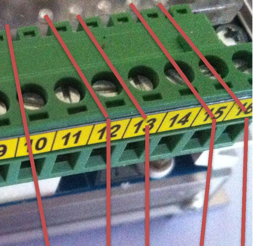
29 Settings SETTING and AND Adjustment ADJUSTMENT STEPS Steps Limit LIMIT Switches SWITCHES and AND PLC TABLE A Table A Steps Actions Comments 1 The door is open and the curtain is wound on the roller in the canopy. 2 Pull the curtain down,manually. For 1 m about. 3 Connect the power supply 220 V AC single phase to the control board on the power terminals of the PLC. 4 Push the emergency push button on the control board lid. 5 Push MENU (SEL) on PLC till when SEt appears on PLC display. 6 SEt flashes. 7 Push and check if the door really closes. If not change 2 motor power supply cables (U V or W) in the power terminals of the PLC. (It doesn t matter if U and V or U and W or V and W). 8 Follow the sequence described on the page 12 in order to make the curtain stretching correct. 9 Start from open door position and push till the curtain bottom edge is 100 mm over the safety photocells. (Check also the sense of the rotation for the limit switch unit). 10 Adjust the cam corresponding to the brown cable, rotating it till a click sounds and the LED 16 switches off. 11 Push till the curtain bottom edge is 600 mm under the canopy. Adjust the cam corresponding to the white cable rotating it till a click sounds and the LED 15 switches off. 12 Push till the door is open (at the clear opening height). 13 Adjust the cam, rotating it till a click sounds and the LED 13 switches off. 14 Push till the door is closed. LEDs must be switched ON. 15 Push till the curtain bottom edge is between 100 mm over the safety photocells and 600 lower than the canopy. LEDs must be ON. 16 Push till the door will be open. LEDs Push and SEt doesn t flash. 18 Release the emergency push button. 19 Push the opening push button on the control board lid. After some seconds the door closes. The door closes slow. Other steps are shown in the following page sales@indupart.co.uk 29
30 Settings and Adjustment Steps Limit Switches and PLC Table B Steps Actions Comments 20 Push the opening push button. Verify the complete cycle opening dwell closing. Check if the dwell time is the wished one. Check if the accelerations and decelerations are correct. The door should open slow fast slow. The door should close slow fast slow. 21 Check the closing speed slows down at about 100 mm over the photocells. If not move the related cam forward ¼ of turn. 22 The door probably doesn t close perfectly. The curtain bottom edge probably stops some cm over the floor. 23 In this case push till UcL is shown on the display. 24 Push to increase the time for 4 or 5 digits. 25 Push to confirm 26 Push the opening push button and check if the door close correctly. If not repeat actions The curtain bottom edge must lightly touch the floor. 27 When the door is closing cross the beam between safety photocells. The door stops and changes the movement direction. It opens and then closes. After an emergency intervention the door closes slowly. 28 If the door doesn t close correctly,push till UoF will be shown on the display. 29 Push or basing on the before watched situation. 30 Push to confirm sales@indupart.co.uk
BELT Rapid Fold up Door
 BELT Rapid Fold up Door Quick Assembling Guidebook Belt Manualopen Basic Safety Edge 0161 432 6655 sales@indupart.co.uk /indupart /indupart /indupart /company/indupart-ltd Table of Contents Table of contents
BELT Rapid Fold up Door
 BELT Rapid Fold up Door Quick Assembling Guidebook Belt Clear Opening Dimensions more then 5000 x 5000mm Manualopen Easy Safety Edge 0161 432 6655 sales@indupart.co.uk /indupart /indupart /indupart /company/indupart-ltd
SYMBOL LEGEND DANGER WARNING NOTE THIS INDICATES DANGER TO THE LIFE AND HEALTH OF THE USER IS APPROPRIATE PRECAUTIONS ARE NOT TAKEN
 SYMBOL LEGEND DANGER THIS INDICATES DANGER TO THE LIFE AND HEALTH OF THE USER IS APPROPRIATE PRECAUTIONS ARE NOT TAKEN WARNING THIS WARNS THAT MATERIALS MAY BE DAMAGED IF APPROPRIATE PRECAUTIONS ARE NOT
B.M.P. DOORS LTD INDUSTRIAL RAPID DOORS
 B.M.P. DOORS LTD INDUSTRIAL RAPID DOORS Web site : www.bmpdoors.co.uk e-mail : info@bmpdoors.co.uk THERMICHROLL KOMBY ENGLISH INSTALLATION MANUAL IMPORTANT Read this manual carefully before installing
SYMBOL LEGEND DANGER WARNING NOTE THIS INDICATES DANGER TO THE LIFE AND HEALTH OF THE USER IS APPROPRIATE PRECAUTIONS ARE NOT TAKEN
 SYMBOL LEGEND DANGER THIS INDICATES DANGER TO THE LIFE AND HEALTH OF THE USER IS APPROPRIATE PRECAUTIONS ARE NOT TAKEN WARNING THIS WARNS THAT MATERIALS MAY BE DAMAGED IF APPROPRIATE PRECAUTIONS ARE NOT
CONTROL UNIT BIOS2. Manual for installation. Programmable Control board for wings gates.
 Programmable Control board for wings gates www.remotecontrolgates.co.uk Manual for installation Compatible from firmware version BIOS2BT02 CONTROL UNIT BIOS2 1. Introduzione The control unit BIOS2 is particularly
Installing the gate post bracket with the cardboard arm template
 ......... Installing the gate post bracket with the cardboard arm template... Installing gate posts brackets and arms for Push-to-Open or Pull-to-Open gates... Connection of Power Source 240Vac or Solar...
Installing the gate post bracket with the cardboard arm template
 ......... Installing the gate post bracket with the cardboard arm template... Installing gate posts brackets and arms for Push-to-Open or Pull-to-Open gates... Connection of Power Source 240Vac or Solar...
AQUASTAR C6. (Comfort 6000) Next Generation Auto Backwash Valve System. (selectable time-pressure or remote cycle start)
 Next Generation Auto Backwash Valve System. (selectable time-pressure or remote cycle start)") AQUASTAR C6 (Comfort 6000) Next Generation Auto Backwash Valve System (selectable time-pressure or remote cycle start) SIDE MOUNTED AND TOP MOUNTED VALVES WITH QUICK INSTALL ELECTRIC ACTUATORS FOR PIPE
AQUASTAR C6 (Comfort 6000) Next Generation Auto Backwash Valve System (selectable time-pressure or remote cycle start) SIDE MOUNTED AND TOP MOUNTED VALVES WITH QUICK INSTALL ELECTRIC ACTUATORS FOR PIPE
CD100 Series. Operators Manual SINGLE COLUMN CARD DISPENSER
 CD100 Series SINGLE COLUMN CARD DISPENSER Operators Manual Contents 1 Specifications...1 2 Installation...2 2.1 Unpacking and inspection...2 2.2 Installation...2 2.3 Electrical Connections...2 2.4 Initial
TECHNICAL MANUAL AND ELECTRONICAL MODULE REGULATION VVVF-4 +
 TECHNICAL MANUAL AND ELECTRONICAL MODULE REGULATION VVVF-4 + 8 CABIN DOORS DESCRIPTION OF SWITCHES The unit may be programmed using the DIL switches on the front of the unit. If any change is made to any
INSTRUCTION INVERTER COMPACT FOR SLIDING GATES /R0 10/11/2017
 INSTRUCTI INVERTER COMPACT FOR SLIDING GATES 6-1622616 /R0 10/11/2017 2 / 20 3 / 20 1. INTRO The control unit INVERTER COMPACT is integrated in the motor KALOS XL. It is a device suitable for operating
OPERATION MANUAL Common for All models. Weft Sensor (Weft Break Detection) AS - 35 A - 35 MSD10-24 (PNP/NPN)
 AS - 35 A - 35 MSD10-24 (PNP/NPN)") OPERATION MANUAL Common for All models Weft (Weft Break Detection) A - 35 MSD10-24 (PNP/NPN) Beta Computronics pvt. Ltd. 10/1 IT Park, Parsodi, Nagpur-440022 (MS), INDIA. Phone :+91-712-2227125, 2240122
OPERATION MANUAL Common for All models Weft (Weft Break Detection) A - 35 MSD10-24 (PNP/NPN) Beta Computronics pvt. Ltd. 10/1 IT Park, Parsodi, Nagpur-440022 (MS), INDIA. Phone :+91-712-2227125, 2240122
Rolling Door Operator User s Manual
 Rolling Door Operator User s Manual MODEL: RSI-500KG Rolling Steel Ind. Brooklyn NY Tel. 718 272-4444 OUTLINE 1. Important safety information 1 2. Main technical parameters 1 3. Introduction 1 4. Installation
Setup and Programming Manual
 Microprocessor and Handy Terminal Setup and Programming Manual Versions U04 to U19 for Sliding Door Systems P/N 159000 Rev 7-2-07 The manufacturer, NABCO Entrances, Inc. suggests that this manual be given
OPERATION MANUAL Common for All models Bobbin Sensor (Weft End Detection) DP150 - L2 BP150 - L2-12V BP150 - L2-24V (PNP/NPN)
 DP150 - L2 BP150 - L2-12V BP150 - L2-24V (PNP/NPN)") OPERATION MANUAL Common for All models Bobbin Sensor (Weft End Detection) DP150 - L2 BP150 - L2-12V BP150 - L2-24V (PNP/NPN) Beta Computronics pvt. Ltd. 10/1 IT Park, Parsodi, Nagpur-440022 (MS), INDIA.
OPERATION MANUAL Common for All models Bobbin Sensor (Weft End Detection) DP150 - L2 BP150 - L2-12V BP150 - L2-24V (PNP/NPN) Beta Computronics pvt. Ltd. 10/1 IT Park, Parsodi, Nagpur-440022 (MS), INDIA.
Gate & Door Controller with LCD and Intelligent Technology
 2nd Edition Gate & Door Controller with LCD and Intelligent Technology 24Sv1 and 12Sv1 Motor Controllers Setup and Technical information for single motor controller for gates & doors Includes latest Intelligent
BG45 BG65S BG75 Axial Parallel Axial Parallel Axial Parallel CASM-32 (LS/BS/BN) X X CASM-40 (LS/BS/BN) X X X X CASM-63 (LS/BN/BF) X X
 X X CASM-40 (LS/BS/BN) X X X X CASM-63 (LS/BN/BF) X X") 1 System Overview CASM electric cylinders powered by brushless DC motors are ideally suited for fast and powerful movements. Replacement of pneumatic cylinders has never been easier. Just parameterize
1 System Overview CASM electric cylinders powered by brushless DC motors are ideally suited for fast and powerful movements. Replacement of pneumatic cylinders has never been easier. Just parameterize
Instruction Manual. Duo-battery Solar Panel Controller EPIP20-DB series For Both 10 and 20 amp. Controllers (for use with solar panels only) + -
 + -") Instruction Manual Duo-battery Solar Panel Controller EPIP20-DB series For Both 10 and 20 amp. Controllers (for use with solar panels only) + - Optional - Switch to disconnect solar panel when engine alternator
Instruction Manual Duo-battery Solar Panel Controller EPIP20-DB series For Both 10 and 20 amp. Controllers (for use with solar panels only) + - Optional - Switch to disconnect solar panel when engine alternator
Installation and Maintenance Instructions. World Leader in Modular Torque Limiters. PTM-4 Load Monitor
 World Leader in Modular Torque Limiters Installation and Maintenance Instructions PTM-4 Load Monitor 1304 Twin Oaks Street Wichita Falls, Texas 76302 (940) 723-7800 Fax: (940) 723-7888 E-mail: sales@brunelcorp.com
Intelli-Feed Controller User s Manual Intelli-Feed Digital Tachometer and Hourmeter
 Intelli-Feed Controller User s Manual Intelli-Feed Digital Tachometer and Hourmeter Part #: 9047 Table of Contents: Table of Contents 2 Intelli-Feed TM User Interface 3 Equipment Diagnostic Indicators
Combined Ventilation Controller RVWS-T-224HA
 Combined Ventilation Controller RVWS-T-224HA 8-stage Control for Power/Natural Applications 2 variable speed stages, 2 curtain winch stages, 2 fixed speed ventilation stages, 1 thermo/mister cycle stage
PY600AC Sliding Gate Opener User Manual
 PY600AC Sliding Gate Opener User Manual 2017 Dear users, Thank you for choosing this product. Please read the manual carefully before assembling and using it. Please do not leave out the manual if you
Single or Double 240VAC motor control for domestic and industrial gates and doors.
 COBO30 Double 240V Motor Drive Controller Features For 240Volt Motors Auto Closing Open Only Security Closing and Extended Lock Pulse (user selectable) Travel Timer Push Button Input Photo Cell Input Option
3200NT Timer Service Manual
 Service Manual Valve Serial Number Valve Position 1-LEAd 2-LAg 3-LAg 4-LAg IMPORTANT: Fill in pertinent information on page 3 for future reference. Table of Contents Job Specifications Sheet.....................................................................
SK-10. Features. Solar Charge Controller User Manual. Important Safety Information
 SK-10 Solar Charge Controller User Manual 12V/24V 10Amp Dear Users: Thank you for selecting our product. Please read this manual carefully before you use this product. This product is of cutting edge design,
Installation and Maintenancee Manual
 Installation and Maintenancee Manual Commercial Boom Gate Operator Model: GDS BOOM 4 and 6 A.B.N. 62 059 806 405 Nov 2013 Section No: CONTENTS Page Number: 1 Safety Precautions 3 2 Specifications 4 3 Mechanical
QUADSCAN User s Guide Door Mounted Presence sensor
 QUADSCAN User s Guide Door Mounted Presence sensor DESCRIPTION 6 7 8 9 0. housing. clip. main connector. DIP-switch. range adjustment screw 6. receiver 7. end cap 8. clip with angle adjustment screw 9.
FM200 FLOW/NO-FLOW MONITOR INSTALLATION AND TECHNICAL MANUAL 120 VAC MODEL 6/1/2017
 FM200 FLOW/NO-FLOW MONITOR INSTALLATION AND TECHNICAL MANUAL 120 VAC MODEL 6/1/2017 Maxi-Tronic, Inc. 417 Wards Corner Road Loveland, OH 45140 513.398.2500 800.659.8250 FAX: 513.398.2536 info@maxitronic.com
MODEL RMS INSTALLATION INSTRUCTIONS. CONTENTS Page A. Introduction 1. Usage 2 2. How it operates 2
 CONVEYOR COMPONENTS COMPANY Division of Material Control, Inc. 130 Seltzer Road, PO Box 167 Croswell, MI 48422 USA PHONE: (810) 679-4211 TOLL FREE (800) 233-3233 FAX: (810) 679-4510 Email: info@conveyorcomponents.com
Attention! 1 Accessories. 2-1 Installation description ❹ ❺. Please proceed as follows
 Thank you for purchasing the TNT-B meter for Yamaha Bolt. Before installing, please read the instruction carefully and keep it for future reference. Attention! For installation, please follow the steps
CABINET REEL OPERATING INSTRUCTIONS
 CABINET REEL OPERATING INSTRUCTIONS MODELS 15, 25, 40 & 60 SERIES RAPID-AIR CORPORATION 4601 KISHWAUKEE ST. ROCKFORD, IL 61109-2925 Phone: (815) 397-2578 Fax: (815) 398-3887 Web Site: www.rapidair.com
INSTRUCTION MANUAL_1219_ENGLISH SUPER ELF X3. Operating Instructions for DORNIER looms. Robustness Reliability Quality Productivity Versatility
 INSTRUCTION MANUAL_1219_ENGLISH SUPER ELF X3 Operating Instructions for DORNIER looms Robustness Reliability Quality Productivity Versatility WARNING! - Condensation could form on the Weft Feeder when
Merih DDCA60 Operation and User Manual I Merih Asansör A.Ş.
 1. WARNINGS! CAUTION This manual contains user guidelines for Merih DDCA60 hardware version v1.05 and software version v1.03. This document will be updated with differences result from version differences.
1. WARNINGS CAUTION BEFORE FIRST USE GENERAL NOTE. Merih DDCA60 Operation and User Manual I Merih Asansör A.Ş.
 1. WARNINGS! CAUTION This manual contains user guidelines for Merih DDCA60 hardware version v1.05 and software version v1.03. This document will be updated with differences result from version differences.
BARRY BARRIER GATE AUTOMATION
 BARRY BARRIER GATE AUTOMATION Installation Manual 1. WARNINGS AND GENERAL SAFETY INSTUCTIONS This manual contains important safety information. An incorrect installation or an improper use may cause serious
12V PROGRAMMABLE POWER OUT
 Page 1 ACCESSORIES STARTER IGNITION BATTERY WIRES SIDE VIEW BLUE RED YELLOW 30 A 10 A BLUE / WHITE YELLOW WHITE / BLUE WHITE / DOOR TRIGGER See opt. 16 DOOR TRIGGER (input positive) See opt. 16 PARKING
Idle Timer Controller - ITC515-A Ford Transit Contact InterMotive for additional vehicle applications
 An ISO 9001:2008 Registered Company Idle Timer Controller - ITC515-A 2015-2018 Ford Transit Contact InterMotive for additional vehicle applications Overview The ITC515-A system will shut off gas or diesel
Installation Instructions - K-Safe-T-Rip Belt Rip Detector
 Kinder Australia product: Preferred Setup Instructions Note: The correct Belt Rip pick up detachment operation of the Rip Socket, is in a sideways motion to the attachment point. This means once the Socket
Greddy E-manage Installation and Tuning Information
 Greddy E-manage Installation and Tuning Information Overview The Emanage has a lot of functionality considering it is still a piggyback type engine management system and not a full standalone. By itself,
SERIES 700/700E FACTORY KEYLESS UPGRADE INSTALLATION MANUAL
 SERIES 700/700E FACTORY KEYLESS UPGRADE INSTALLATION MANUAL Items Supplied with the System: Installation Instructions: Main unit 1. Mounting the module: Plug In LED Mount the module in a suitable location
FM SECURITY AND REMOTE START SYSTEM
 FM SECURITY AND REMOTE START SYSTEM INSTALLATION MANUAL BEFORE INSTALLING THIS PRODUCT PLEASE READ THIS INSTALLATION MANUAL THOROUGHLY!! This system is intended for installation on vehicles equipped with
STRAIGHTENER OPERATING INSTRUCTIONS
 STRAIGHTENER OPERATING INSTRUCTIONS MODELS SBX SERIES (ADJUSTABLE PLATEN STOCK STRAIGHTENER INCLUDES SA3 THROUGH SCX) (6-01) RAPID-AIR CORPORATION 4601 KISHWAUKEE ST. ROCKFORD, IL 61109-2925 Phone: (815)
STRAIGHTENER OPERATING INSTRUCTIONS
 STRAIGHTENER OPERATING INSTRUCTIONS MODELS SBX, SCX & SD SERIES (4-02) RAPID-AIR CORPORATION 4601 KISHWAUKEE ST. ROCKFORD, IL 61109-2925 Phone: (815) 397-2578 Fax: (815) 398-3887 Web Site: www.rapidair.com
ASSEMBLING & REGULATION INSTRUCTIONS FOR AYTOMATIC CABIN DOORS
 ΕΓΧΕΙΡΙΔΙΟ ΤΟΠΟΘΕΤΗΣΗΣ & ΡΥΘΜΙΣΗΣ ΑΥΤΟΜΑΤΩΝ ΠΟΡΤΩΝ ΘΑΛΑΜΟΥ ASSEMBLING & REGULATION INSTRUCTIONS FOR AYTOMATIC CABIN DOORS CABIN DOORS INDEX PARTS DESCRIPTION 26 POSITION OF THE OPERATOR IN THE CABIN 26
SAFE AND SECURE EXTREME R MOTOR OWNER'S MANUAL MODEL PRO-FDG FOR TECHNICAL SUPPORT PLEASE CALL 1-(855) OPERATOR SERIAL#
 OPERATOR SERIAL#") SAFE AND SECURE EXTREME R MOTOR OWNER'S MANUAL MODEL PRO-FDG FOR TECHNICAL SUPPORT PLEASE CALL 1-(855) 594-4969 3121B(4) ECN 1288 BY TG 2/6/15 OPERATOR SERIAL# PRO-FDG MOTOR OPERATORS MOTOR OWNER'S MANUAL
SAFE AND SECURE EXTREME R MOTOR OWNER'S MANUAL MODEL PRO-FDG FOR TECHNICAL SUPPORT PLEASE CALL 1-(855) 594-4969 3121B(4) ECN 1288 BY TG 2/6/15 OPERATOR SERIAL# PRO-FDG MOTOR OPERATORS MOTOR OWNER'S MANUAL
Gobius 1, Level Switch for Water, Fuel and Fluid Tanks, new version 5.0. Installation Guide. Before you begin
 Document release, 5.12, July 2017 Gobius 1, Level Switch for Water, Fuel and Fluid Tanks, new version 5.0 Installation Guide Before you begin 1. Please make sure that no part is missing. 1 sensor, 1 panel,
Controls F792 Switchbox LP Series
 Controls F792 Switchbox LP Series The well proven design of the Keystone F792 Low Profile Switchbox has been upgraded to simplify setting, site wiring and weatherproof integrity. Features Cams specially
SPA MICROPROCESSOR COMBINED TACHO&SPEEDO/GAUGE INSTALLATION AND OPERATING MANUAL PAGE 2...INSTRUMENT FEATURES PAGE 3...OPERATING INSTRUCTIONS
 SPA MICROPROCESSOR COMBINED TACHO&SPEEDO/GAUGE INSTALLATION AND OPERATING MANUAL PAGE 2...INSTRUMENT FEATURES PAGE 3...OPERATING INSTRUCTIONS PAGE 3...MENU SYSTEM PAGE 11...INSTALLATION DIAGRAMS PAGE 15...INSTALLATION
Powertrain DTC Summaries EOBD
 Powertrain DTC Summaries Quick Reference Diagnostic Guide Jaguar X-TYPE 2.0 L 2002.25 Model Year Refer to page 2 for important information regarding the use of Powertrain DTC Summaries. Jaguar X-TYPE 2.0
Owner s Manual. For SOLAR BOOM GATE. Model: CA-5000 SOLAR
 ECA Electronic Engineering Pty. LTD. Australia Tel: 03-95720 535 Fax: 95 720 536 Owner s Manual For SOLAR BOOM GATE Model: CA-5000 SOLAR ( 2009 / Version 1 ) 1 1 Introduction 1.0 Control PCB Wiring INSTALLATION
Yaskawa AC Drive L1000A Supplement to the L1000A Technical Manual No. SIEP C , SIEP C , and SIEP C
 Yaskawa AC Drive L1000A Supplement to the L1000A Technical Manual No. SIEP C710616 32, SIEP C710616 33, and SIEP C710616 38 Introduction This supplement to the L1000A Technical Manual describes features
J3C-L Nm Smart Electric Valve Actuator Failsafe Function Type: J3C Model: L140-BSR
 Failsafe Function Type: JC Model: L140-BSR Feature rich J+J multi-voltage smart electric actuator with LED status light and function conversion kits. Overview The JC-L140 low voltage electric valve actuator
Magnetek DSD 412 Drive
 DRIVE STARTUP MANUAL Magnetek DSD 412 Drive Induction Motor Installation www.smartrise.us 2601 Fair Oaks Blvd., Sacramento, CA 95864 916.457.5129 Magnetek DSD 412 Drive EQUIPMENT/SETTINGS VERIFICATION
Index. Index...pag.1. General features...pag.2 Mechanical features Available size. Electrical features pag.3 Protections Signalling Led
 MANUAL Micro Driver Via Ilaria Alpi N 6 - zona industriale - Lonato (BS) Tel. 030/9913491r.a. Fax. 030/9913504 http://www.re-elettronica.it E-mail : info@re-elettronica.it Pag. 1 Index Index........pag.1
BOX A3 TEST REL. DATE R.T. Check and Approval
 BOX A3 TEST 3 20-07-2012 REL. DATE R.T. Check and Approval INDEX 1 - FOREWORD......Page 3 2 - BOX A3 TEST FOR HYDRAULIC LIFTS...Page 3 2.1 GENERAL OPERATION...Page 3 2.2 HOW THE CHECK OF THE VALVE HYDRAULIC
Technical Manual DICTAMAT 304 AZ. Door Drive Unit. for hinged lift landing doors. Technical Data
 Door Drive Unit The is an electrical door drive unit which automatically opens hinged lift doors up to 200 kg. As the operating arm is not directly fixed to the door, all landing doors in the lift can
SE-3SCR-LM MANUAL MOTOR LOAD MANAGER
 3714 Kinnear Place Saskatoon, SK Canada S7P 0A6 Ph: (306) 373-5505 Fx: (306) 374-2245 www.littelfuse.com/relayscontrols SE-3SCR-LM MANUAL MOTOR LOAD MANAGER MARCH 5, 2013 REVISION 4 MOTOR LOAD MANAGER
WIŚNIOWSKI roller doors constitute an ideal choice for those who value comfort, durability and aesthetics
 ROLLER DOOR WIŚNIOWSKI roller doors constitute an ideal choice for those who value comfort, durability and aesthetics 6 ADVANTAGES COMFORT AS STANDARD All WIŚNIOWSKI roller doors are equipped as standard
Gobius 4 for Waste Holding Tanks, new version 5.0
 Document release 5.12, July 2017 Gobius 4 for Waste Holding Tanks, new version 5.0 Installation Guide Before you begin 1. Please make sure that no part is missing. 3 sensors, 1 panel, 1 control unit, 1
Installation and use. Controller for Rapid Bike Evo and Rapid Bike Racing modules. Issued by: PM approved by DG Rev.00 date 09/01/15 pag.
 Installation and use Controller for Rapid Bike Evo and Rapid Bike Racing modules Issued by: PM approved by DG Rev.00 date 09/01/15 pag. 1/10 Description YOUTUNE is a calibration device showing data relative
Table of Contents. General Operation. 3 How Slam-A-Winner plays How the Wheel Scores How the Ball Lift works Programming Options...
 61-MAN-B Table of Contents General Operation. 3 How Slam-A-Winner plays How the Wheel Scores How the Ball Lift works Programming Options... 4-6 Troubleshooting Guide. 7-8 Parts Identification 9 Schematics
CPi. CoiL PACK IGNiTioN FOR AViATiON. For 4,6 and 8 cylinder 4 stroke applications. Please read the entire manual before beginning installation.
 1 CPi CoiL PACK IGNiTioN FOR AViATiON Coil pack (4 cylinder) Coil pack (6 cylinder) For 4,6 and 8 cylinder 4 stroke applications. Please read the entire manual before beginning installation. Software version
Overview of operation modes
 Overview of operation modes There are three main operation modes available. Any of the modes can be selected at any time. The three main modes are: manual, automatic and mappable modes 1 to 4. The MapDCCD
Automatic Swing door Operator SD3108 Product manual. Notes: please keep the manual properly for reference. Do carefully read this manual before use.
 Automatic Swing door Operator SD3108 Product manual Notes: please keep the manual properly for reference. Do carefully read this manual before use. Safety Warning! Please read carefully the instructions
SPA MICROPROCESSOR 3 STAGE PROGRAMMABLE SHIFT LIGHT INSTALLATION AND OPERATING MANUAL PAGE 2...INSTRUMENT FEATURES. PAGE 3...OPERATING INSTRUCTIONS.
 SPA MICROPROCESSOR 3 STAGE PROGRAMMABLE SHIFT LIGHT INSTALLATION AND OPERATING MANUAL PAGE 2...INSTRUMENT FEATURES. PAGE 3...OPERATING INSTRUCTIONS. PAGE 4...MENU SYSTEM. PAGE 6...SPECIFICATIONS. PAGE
PALLET MASTER (PMD) OPERATING INSTRUCTIONS
 OPERATING INSTRUCTIONS") PALLET MASTER (PMD) OPERATING INSTRUCTIONS MODELS (INCLUDES PMD35 & PMD50. 115VAC, 1PH, 60HZ) RAPID-AIR CORPORATION 4601 KISHWAUKEE ST. ROCKFORD, IL 61109-2925 Phone: (815) 397-2578 Fax: (815) 398-3887
PALLET MASTER (PMD) OPERATING INSTRUCTIONS MODELS (INCLUDES PMD35 & PMD50. 115VAC, 1PH, 60HZ) RAPID-AIR CORPORATION 4601 KISHWAUKEE ST. ROCKFORD, IL 61109-2925 Phone: (815) 397-2578 Fax: (815) 398-3887
VoloMOD Full Feature Installation (Turn signals
 VoloMOD Full Feature Installation (Turn signals output) In the Full Featured installation mode, VoloMOD flashes your turn signal lights at two different rates to provide an early indication of deceleration
Adaptive cruise control (ACC)
") Adaptive cruise control (ACC) PRINCIPLE OF OPERATION The Adaptive Cruise Control (ACC) system is designed to aid the driver to maintain a gap from the vehicle ahead or a set road speed if there is no slower
Adaptive cruise control (ACC) PRINCIPLE OF OPERATION The Adaptive Cruise Control (ACC) system is designed to aid the driver to maintain a gap from the vehicle ahead or a set road speed if there is no slower
Automotive Application ET01 Software Revision A 12/06
 Automotive Application ET01 Software Revision A 12/06 INTRODUCTION... 2 FUNCTIONAL DESCRIPTION... 3 INSTALLATION... 4 COMPONENT PLACEMENT... 4 PLUMBING AND WIRING... 5 MSBC OPERATION (ET-01)... 14 TIMED
LIFTMASTER MAGIC BUTTON FS10 & LPK5 FAST SLIDER
 R MAGIC BUTTON FS0 & LPK5 FAST SLIDER OPERATORS MANUAL FEATURES High speed -800mm/second Corrosion resistant - Hot dip galvanised base with stainless steel cover Speed flexibility - Slow start / slow stop
INSTALLATION INSTRUCTIONS FOR SYMCOM'S MODEL 777-HVR-SP ELECTRONIC OVERLOAD RELAY
 CONNECTIONS INSTALLATION INSTRUCTIONS FOR SYMCOM'S MODEL 777-HVR-SP ELECTRONIC OVERLOAD RELAY BE SURE POWER IS DISCONNECTED PRIOR TO INSTALLATION!! FOLLOW NATIONAL, STATE AND LOCAL CODES! READ THESE INSTRUCTIONS
POLE STAR PRO. Installation and instruction manual.
 POLE STAR PRO Installation and instruction manual. POLE STAR PRO is an automatic chrono and rev counter with a LED bar and Shift light which can be set, an indispensable instrument for drivers of: Go Karts
Gobius 1, Level Switch for Water, Fluid & Fuel Tanks
 Document release 1.0, September 2013 Gobius 1, Level Switch for Water, Fluid & Fuel Tanks Installation Guide Before you begin 1. Please make sure that no part is missing. (1 sensor, 1 panel, 1 control
SECEUROGLIDE ROLLER GARAGE DOORS, SECEUROSHIELD, SECEUROSCREEN & SECEUROVISION ROLLER SHUTTERS CONTENTS
 Operating & Maintenance Instructions SECEUROGLIDE ROLLER GARAGE DOORS, July 2007 Issue 4 SECEUROSHIELD, SECEUROSCREEN & SECEUROVISION ROLLER SHUTTERS CONTENTS Page 1. General Instructions 2 2. Operating
DUAL DIGIT COUNTDOWN TIMER MANUAL
 DUAL DIGIT COUNTDOWN TIMER MANUAL 2 3 Topline Electronics Ltd Introduction Topline were established in 1986 to provide high quality equipment. Topline now provide integrated dosing equipment packages with
K10 Intrinsically Safe Electro-Pneumatic Positioner Operating Manual
 K0 Intrinsically Safe Electro-Pneumatic Positioner Operating Manual Pneumatic Connection Outlet Port Gauge Single Acting Actuator (Spring Return): For single acting actuators Outlet Port 2 is to be plugged.
RR Concepts. The StationMaster can control DC trains or DCC equipped trains set to linear mode.
 Jan, 0 S RR Concepts M tation aster - 5 Train Controller - V software This manual contains detailed hookup and programming instructions for the StationMaster train controller available in a AMP or 0AMP
MODEL CMS INSTALLATION INSTRUCTIONS A. INTRODUCTION 1. USAGE 2 2. HOW IT OPERATES 2 B. SPECIFICATIONS 1. ELECTRICAL 3 2.
 CONVEYOR COMPONENTS COMPANY 130 Seltzer Road, PO Box 167 Croswell, MI 48422 USA PHONE: (810) 679-4211 TOLL FREE (800) 233-3233 FAX: (810) 679-4510 Email: info@conveyorcomponents.com http://www.conveyorcomponents.com
Visit our web site at AMR LS-3000, LS-3010 & LS-3020 BELT SLIP/SEQUENCE CONTROL INSTALLATION AND SETUP INSTRUCTIONS
 AMR INC. DESIGN & MANUFACTURING FOR MINING WORLDWIDE P.O. BOX 234, ROCKY GAP, VA 24366 PHONE (276)928-1712 FAX (276)928-1814 Email sales@americanmineresearch.com Visit our web site at www.americanmineresearch.com
VER KIT. Installation Instructions TECHNICAL HELPLINE
 CAME UNITED KINGDOM LTD UNIT 3 ORCHARD PARK INDUSTRIAL ESTATE, TOWN STREET, SANDIACRE, NOTTINGHAM NG10 5BP TEL: 0115 921 0430 FAX: 0115 921 0431 TECHNICAL HELPLINE 0115 921 0430 INTERNET - www.cameuk.com
APPLICATION GUIDE. Pure easiness for a wide range of applications ACS580 general purpose drives
 APPLICATION GUIDE Pure easiness for a wide range of applications ACS580 general purpose drives 2 APPLICATION GUIDE ACS580 PURE EASINESS FOR MANY PURPOSES Table of contents 3 Pure easiness for many applications
Adaptive cruise control (ACC)
") Adaptive cruise control (ACC) PRINCIPLE OF OPERATION WARNING Adaptive Cruise Control is not a collision warning or avoidance system. Additionally, Adaptive Cruise Control will not detect: stationary or
Adaptive cruise control (ACC) PRINCIPLE OF OPERATION WARNING Adaptive Cruise Control is not a collision warning or avoidance system. Additionally, Adaptive Cruise Control will not detect: stationary or
ACTUATORS POSITION SENSOR
 POSITION SENSOR 1 2 SUMMARY P INTRODUCTION PAGE 4 P LTS POSITION SENSOR PAGE 5 P LTL POSITION SENSOR PAGE 9 SUMMARY P LTE POSITION SENSOR PAGE 12 3 INTRODUCTION INTRODUCTION Magnetic position sensors are
Self-Repairable High Speed Doors Standard Interior - 100SR Low-Temp - 104SF Interior Reinforced - 110RI Exterior Reinforced - 140RA
 Self-Repairable High Speed Doors Standard Interior - 100SR Low-Temp - 104SF Interior Reinforced - 110RI Exterior Reinforced - 140RA Interior / Reinforced-Interior High Speed Doors 100SR Interior and 110RI
MB A 12V/24V DC PROGRAMMABLE DUAL BATTERY ISOLATOR
 MB-3688 120A 12V/24V DC PROGRAMMABLE DUAL BATTERY ISOLATOR User Manual Warning and Precautions MB-3688 is built with corrosion resistant material and the main electronic assembly is well sealed inside
Electrical Options Booklet. Table of Contents
 *24228413* 24228413 Electrical Options Booklet Table of Contents EL Wiring... EL Troubleshooting... SD/EL 98/99 Cylinder Dogging... SS Wiring... 330, 350, RX-330 and RX-350 Push Bar Trim Mechanical Installation...
6R / 5-BUTTON SERIES VEHICLE SECURITY SYSTEM
 6R / 5-BUTTON SERIES VEHICLE SECURITY SYSTEM Button 1 Button 2 Button 5 Button 3 Button 4 Standard Features: Two 5-Button Remote Transmitters Status indicator (LED) Valet / override switch Multi-tone siren
SLIDING DOOR OPERATOR INSTRUCTION MANUAL
 SLIDING DOOR OPERATOR INSTRUCTION MANUAL (MODEL NO. 1071.101 & 1071.102) Please carefully keep this manual for good maintenance. Caution Be sure the door opener is far away from moisture, vibration, and
User Manual. T6 Tachometer. Online: Telephone: P.O. Box St. Petersburg, Florida 33736
 User Manual T6 Tachometer Online: www.phareselectronics.com Telephone: 727-623-0894 P.O. Box 67251 St. Petersburg, Florida 33736 Table of Contents Overview... 1 Description... 1 Wiring... 1 T6 Tachometer
REVISION HISTORY REVISION HISTORY
 FILTER CONTROLLER REVISION HISTORY Filter Flush Controller forms part of the Netafim range of filtration controllers all designed to make filteration more reliable and economical.. Contact any of the Netafim
JR XP9303 Programming Guide for the Hangar Size P-51
 By Danny Snyder JR XP9303 Programming Guide for the Hangar 9 1.50 Size P-51 This guide will assist in the programming necessary to set up the 1.50 Size Hangar 9 P-51 Mustang, though the information could
Laboratory 10 Assignment. Introduction
 ME576 Laboratory 10 Assignment Introduction For this lab, the conveyor trainer will be operated using the Siemens S5 PLC. The conveyor system is supposed to sort the metal pegs from rings on the moving
SB 2000 PUSH TO SEARCH NEXT STAG E. Aerotech, Inc. FORM: QM 1320
 Inlet Controller SB 2000 USER'S MANUAL AUTO OPEN MANUAL PUSH TO SEARCH NEXT STAG E CLOSE Aerotech, Inc. FORM: QM 1320 4215 Legion Dr. Mason, MI 48854-1036 USA Rev. 3, Sept. 1997 Ph. (517) 676-7070 Fax
VOLUMETRIC BLENDING SYSTEM OPERATION MANUAL
 VOLUMETRIC BLENDING SYSTEM OPERATION MANUAL 12285 E. MAIN ST. MARSHALL, IL 62441 PHONE: 217-826-6352 FAX: 217-826-8551 WEB SITE: www.yargus.com 1 OPENING SCREEN The OPENING SCREEN is the screen that the
RF-425LCD PROFESSIONAL VEHICLE SECURITY SYSTEM INSTALLATION MANUAL (FOR AUTHORIZED DEALERS ONLY)
") RF-425LCD PROFESSIONAL VEHICLE SECURITY SYSTEM INSTALLATION MANUAL (FOR AUTHORIZED DEALERS ONLY) THIS PRODUCT IS DESIGNED FOR PROFESSIONAL INSTALLATION ONLY 1 BLUE...TRUNK/HOOD TRIGGER (-) INPUT BLACK/BLUE...4TH
RF-425LCD PROFESSIONAL VEHICLE SECURITY SYSTEM INSTALLATION MANUAL (FOR AUTHORIZED DEALERS ONLY) THIS PRODUCT IS DESIGNED FOR PROFESSIONAL INSTALLATION ONLY 1 BLUE...TRUNK/HOOD TRIGGER (-) INPUT BLACK/BLUE...4TH
PRESSURE SENSOR INSTRUCTIONS
 PRESSURE SENSOR INSTRUCTIONS Overview: Pressure sensors are an analog style sensor that produces a voltage from 0V to 5V depending on the amount of pressure applied and the range of the sensor. If you
470nF REG1 LM2940. VR3 100k 10k VR1 100 F. 470pF. 100nF. 100nF RELUCTOR Q2 BC k. 10k TP GND. 2.2nF TO RELUCTOR. 470nF REG1 LM2940 REG1 LM2940
 Where to buy kits Jaycar and Altronics have full kits (including the case) available for the High Energy Electronic Ignition System. The Jaycar kit is Cat. KC-5513 while the Altronics kit is Cat. K4030
TAKE-A-LABEL Power Dr. Nunica, MI Phone: (616) Fax: (616)
 Fax: (616)") OPERATIONS MANUAL MODEL TAL-3100T TAMP APPLICATOR TAKE-A-LABEL 16900 Power Dr. Nunica, MI 49448 Phone: (616) 837-9300 Fax: (616) 937-9301 http://www.take-a-label.com E-Mail sales@take-a-label.com Page
OPERATIONS MANUAL MODEL TAL-3100T TAMP APPLICATOR TAKE-A-LABEL 16900 Power Dr. Nunica, MI 49448 Phone: (616) 837-9300 Fax: (616) 937-9301 http://www.take-a-label.com E-Mail sales@take-a-label.com Page
The Fischertechnik ACEs (Robo Starter Model kit)
") The Fischertechnik ACEs (Robo Starter Model kit) (01) Traffic Light The set of traffic lights is used to stop traffic so a pedestrian can safely cross the road. It has a master switch which can be used
The Fischertechnik ACEs (Robo Starter Model kit) (01) Traffic Light The set of traffic lights is used to stop traffic so a pedestrian can safely cross the road. It has a master switch which can be used