SPA MICROPROCESSOR 3 STAGE PROGRAMMABLE SHIFT LIGHT INSTALLATION AND OPERATING MANUAL PAGE 2...INSTRUMENT FEATURES. PAGE 3...OPERATING INSTRUCTIONS.
|
|
|
- Shawn Quinn
- 5 years ago
- Views:
Transcription
1 SPA MICROPROCESSOR 3 STAGE PROGRAMMABLE SHIFT LIGHT INSTALLATION AND OPERATING MANUAL PAGE 2...INSTRUMENT FEATURES. PAGE 3...OPERATING INSTRUCTIONS. PAGE 4...MENU SYSTEM. PAGE 6...SPECIFICATIONS. PAGE 7...INSTALLATION NOTES. PAGE 8...INSTALLATION SCHEMATIC PAGE 9...WIRING DATA.
2 INSTRUMENT FEATURES SUITABLE FOR ALL ELECTRICAL IGNITION TYPES DIGITAL SETTING OF SHIFT POINT BUILT IN DIGITAL TACHOMETER MICROPROCESSOR ACCURACY MAXIMUM RPM RECALL SETTINGS AND MAXIMUMS STORED INDEFINITELY IN EEPROM MEMORY. MENU SYSTEM FOR :- SETTING THE SHIFT POINTS 100 RPM - 39,900 RPM SETTING THE NUMBER OF CYLINDERS 1-16 SETTING THE IGNITION FILTER ON/OFF RESETTING THE STORED MAXIMUM RPM SETTING THE BACLIGHT ON/OFF (IF FITTED) 2
3 OPERATING INSTRUCTIONS:- When the instrument is first switched you will see SPA displayed momentarily before RPM is displayed as x1000. Pressing the red button after this will recall any stored maximum RPM on the display. The SPA Microprocessor shift light is factory set to standard parameters, but may be adjusted to your requirements using a menu system which will be explained further on. all settings and maximums are stored in EEPROM memory, which will store them for many years without any power needed. As supplied the RPM shift point is set to 8,000 RPM and the cylinders set to 4. The RPM on the LCD display is always updated every 0.3 Sec, but the maximum RPM and shift point detection s are always measured and stored at a much higher rate depending on the engine RPM (typically 40 times a second) for a fast and true response. If the supply voltage to the instrument drops to below 8.00 Volts, a small battery symbol will displayed on the left of the LCD display indicating that battery volts are low. The shift light will still function normally at this voltage, but if the voltage drops down to 7.00 volts, the instrument will reset itself. 3
4 Please note that some of the following features may not be available, depending on the model. MENU SYSTEM:- To access the menu, hold down the red button and then switch on the instrument. On the display you will see "bon" on the LCD display, now release the button. If you now press the red button momentarily again you will see it increment to the next menu option, keep doing this to familiarise yourself with them. The sequence of displays and there meaning is shown below:- bon = Backlight on or, b-- = Backlight off (if fitted). rtp = Reset Peak, IE reset stored maximum RPM to zero. CyL = set the number of engine CyLinders routine. SF1 = set the RPM ShiFt point one (green led) *. SF2 = set the RPM ShiFt point two (yellow led) *. SF3 = set the RPM ShiFt point three (red led). Fon = Filter on or, F-- = Filter off. *Use only on 3 stage model The display then scrolls back round to Reset peaks. To activate any option or routine, press and hold down the red button, the display will change after 2 seconds. A more detailed breakdown of each menu option is detailed on this and the following pages. Bon(BACKLIGHT ON/OFF):- Press and hold down the red button, after 2 seconds the display changes to the desired option. Normally this is set to ON unless you need to reduce battery consumption. rtp(reset PEAKS):- Press and hold down the red button, after 2 seconds the display increments to the next menu item. The stored maximums are now reset to zero. This should be done before any new maximums are to be stored. CyL(SET CYLINDERS):- Press and hold down the red button, after 2 seconds the current cylinders will be displayed. To change the number, press the red button momentarily to increment it one at a time, or press and hold down and the display will count up quickly. When the display reaches 16 it will scroll back round to 1. For certain types of ignition systems, that is ones that have more than one ignition coil per engine, it will be necessary to set the cylinders to a different number than the engine has. If you are using a tacho output from the ignition amplifier box, some systems (like the Ford coil less) give half the ignition pulses and so cylinders would be set to 2. Also most motorcycles use an ignition coil per pair of cylinders, so a 4 cylinder engine would need to be set to 2 on the shift light since it will only see half the number of ignition pulses. 4
5 SF1,2,3(SET SHIFT RPM):- This routine is used to enter the shift points for the engine being used. When the engine RPM exceeds this shift point number, then the appropriate lamp will light. These are:- SF1 - green led SF2 - yellow led SF3 - red led (very bright) Press and hold down the red button, after 2 seconds the current shift point will be displayed as x1000 RPM. To change the number, press the red button momentarily to count it up one hundred RPM at a time, or press and hold and the display will count up quickly. When the display shows it will scroll back round to To exit the routine simply switch off the instrument. NOTE:In practice, you may find that when you look at your Maximum RPM recall, that you have over shot your highest shift point due human reaction time, so you may wish to decrease your shift point(s) to compensate for this and increase the efficiency of your gear shifting further. EG if you set the shift point to 7,900 but you Maximum RPM recall was 8,200 then set your shift point to 7,700 to compensate for your reaction time. Fon(FILTER ON/OFF):- Press and hold down the red button, after 2 seconds the display changes to the desired option. Normally this is set to ON, but if you are using CDI ignition you may have to select it to OFF as the ignition pulses are very short. 5
6 SPECIFICATIONS:- INPUT VOLTAGE VOLTS (working) CONSUMPTION 10 ma(40ma 12 VOLTS FUSE 20mm glass 250mA Fast(F). ACCURACY:- 0.05% CALIBRATION:- DIGITAL DATA STORAGE:- EEPROM WEIGHT:- 190g INCLUDING CABLES ETC SIZE:- 93mm x 39m x 28mm DEEP PLUS 20mm EACH SIDE FOR MOUNTING FEET CABLE LENGTHS:- IGNITION LEAD - 120" POWER SUPPLY -- 12" SHIFT LAMP(S) " ABSOLUTE MAXIMUM RATINGS:- INPUT VOLTAGE - 25 VOLTS ENGINE SPEED - 39,990 RPM INSTRUMENT TEMPERATURE 0-50OC 6
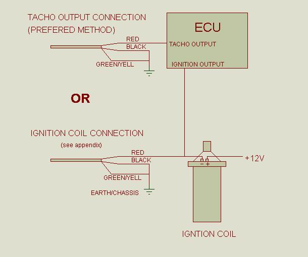
7 INSTALLATION, DO'S & DON'TS :- DO'S DO ensure that the front of the instrument and the exposed plug is protected if it is likely to get any water spray on it. DONT'S DO NOT allow cables to run through sharp edged apertures without protection. DO NOT fix the cables next to or onto any surface likely to exceed 80 degrees Centigrade. The tacho ignition coil input (see schematic) is fully protected. It will easily take pulses up to 500V and is not damaged by reverse polarity. If the suggested connection to the ignition coil does not work, or operation is slightly erratic, please experiment with different connections. IE reverse the polarity of the connections to the coil, and/or try one connection to chassis, and the other to the coil feed. You cannot damage the shift light by doing this. But do not make any kind of connection to the HT leads or spark plugs, this voltage is highly destructive and will likely stop the engine firing properly. You can use a tacho output if this available, and this maybe the only option on some ignition systems. They do vary in there operation however. Some do not like being loaded down to earth (EG Nissan Micra), in this case you need to connect the red wire to +12v batt, and the black wire to tacho output. If the system uses high voltage tacho output (EG Yamaha CDI), then you will need to connect the red wire to the tacho output via a resistor so that it does not load the ignition amplifier excessively (EG 47k for 150V OP), and the black wire to chassis. 7
8 8
9 9
SPA MICROPROCESSOR COMBINED TACHO&SPEEDO/GAUGE INSTALLATION AND OPERATING MANUAL PAGE 2...INSTRUMENT FEATURES PAGE 3...OPERATING INSTRUCTIONS
 SPA MICROPROCESSOR COMBINED TACHO&SPEEDO/GAUGE INSTALLATION AND OPERATING MANUAL PAGE 2...INSTRUMENT FEATURES PAGE 3...OPERATING INSTRUCTIONS PAGE 3...MENU SYSTEM PAGE 9...INSTALLATION DIAGRAMS PAGE 13...INSTALLATION
SPA MICROPROCESSOR 3 STAGE PROGRAMMABLE SHIFT LIGHT INSTALLATION AND OPERATING MANUAL PAGE 2...INSTRUMENT FEATURES. PAGE 3...INSTALLATION NOTES.
 SPA MICROPROCESSOR 3 STAGE PROGRAMMABLE SHIFT LIGHT INSTALLATION AND OPERATING MANUAL PAGE 2...INSTRUMENT FEATURES. PAGE 3...INSTALLATION NOTES. PAGE 4...INSTALLATION SCHEMATIC PAGE 5...OPERATING INSTRUCTIONS.
SPA MICROPROCESSOR COMBINED TACHO&SPEEDO/GAUGE INSTALLATION AND OPERATING MANUAL PAGE 2...INSTRUMENT FEATURES PAGE 3...OPERATING INSTRUCTIONS
 SPA MICROPROCESSOR COMBINED TACHO&SPEEDO/GAUGE INSTALLATION AND OPERATING MANUAL PAGE 2...INSTRUMENT FEATURES PAGE 3...OPERATING INSTRUCTIONS PAGE 3...MENU SYSTEM PAGE 11...INSTALLATION DIAGRAMS PAGE 15...INSTALLATION
SPA DESIGN MICROPROCESSOR DUAL GAUGE MANUAL
 SPA DESIGN MICROPROCESSOR DUAL GAUGE MANUAL SPA MICROPROCESSOR DUAL GAUGE INSTALLATION AND OPERATING MANUAL INSTRUMENT FEATURES PAGE 2 INSTALLATION NOTES PAGE 3 THERMOCOUPLE ADAPTOR BOX PAGE 6 CABLE INSTALLATION
Manual Installation & Operation
 Manual Installation & Operation Model: NCxxLxx 12A or 30A Solid State Solar Charging Regulator and 12A Load Controller. 231 Patent #: 5,642,030 Applies Page 1 Warnings When Installing, connect grounds,
USER MANUAL PCDI-24 PROGRAMMABLE CDI IGNITION
 www.zeeltronic.com info@zeeltronic.com updated 15.01.2009 program version: 00.140109 USER MANUAL PCDI-24 PROGRAMMABLE CDI IGNITION TECHNICAL DATA Limit values: - minimum revs 200 RPM - maximum revs 20000
Switch select of sender types:
 Full sweep minor gauges wiring: B -------------------------------------------------- battery or +12V input. L -------------------------------------------------- LED illumination, for back lighting, dimmable.
Full Sweep Minor Gauge Wiring:
 Full Sweep Minor Gauge Wiring: Notes on Senders: Temp Hi match/vdo 150C: Normally used in Oil temp, 140 280F. Temp Low match/vdo120c: Normally used in water temp, 100 240F. To test the gauges work (oil,
FULL SWEEP STEPPER MOTOR INSTRUMENT KIT INSTRUCTION MANUAL 1969,REDLINE, 2020 SERIES
 FULL SWEEP STEPPER MOTOR INSTRUMENT KIT INSTRUCTION MANUAL 1969,REDLINE, 2020 SERIES REVB071211 INDEX 3-3/8 PROGRAMMABLE SPEEDOMETER 3-3/8 TACHOMETER 2-1/16 GAUGES TEMPERATRURE SENDER PRESSURE SENDER PROGRAMMABLE
BSR Magic Box Digital ignition control for 4, 6, or 8 cylinder engines
 BSR BSR Magic Box Digital ignition control for 4, 6, or 8 cylinder engines Features Digital Advance The main feature of the Magic Box is the digital advance that replaces conventional weights and springs.
DIGITAL GEAR INDICATOR
 DIGITAL GEAR INDICATOR USER GUIDE AND INSTRUCTIONS JULY 2016 CONTENTS INTRODUCTION PAGE 1 INSTALLATION PAGE 2 ENTER MODE PAGE 3 SHIFT LIGHTS - SET LOWER RPM PAGE 4 SHIFT LIGHTS - SET HIGHER RPM PAGE 5
Setup for using our speedometer with GPS sensor
 Setup for using our speedometer with GPS sensor Wiring: Speedometer red (1) power +12V Speedometer black (5) - ground Speedometer green (4) LED illumination (can be 12V) Speedometer blue (7) signal input,
6 Gauge Box Set IS0333
 Caution 6 Gauge Box Set IS0 Rev. B ecr 882 9/202 Disconnect the battery during installation. Tighten nuts on the back clamp only slightly more than you can tighten with your fingers. Six inch-pounds of
INSTALLATION GUIDE Six Gauge Universal Digital Dash Panel Part Number: DP10002
 Made in America Lifetime Guarantee Thank you for purchasing this digital dash panel from Intellitronix. We value our customers! INSTALLATION GUIDE Six Gauge Universal Digital Dash Panel Part Number: DP10002
USER MANUAL PSR-X-T PROGRAMMABLE CDI IGNITION
 www.zeeltronic.com info@zeeltronic.com updated 26.02.2014 program version: 21.140226 USER MANUAL PSR-X-T PROGRAMMABLE CDI IGNITION Very important! Resistor spark plugs must be used, because they produce
Service Manual Model L1000 Smart Lift
 Service Manual Model L1000 Smart Lift Form #1-147 Rev. 10/1/13 Table of Contents Parts Breakdown 3 Monthly Maintenance Checklist 5 Smart Lift Operating Instructions 7 Scale Calibration 8 Advanced Smart
april systems design Ltd
 april systems design Ltd www.aprilsystems.co.uk Detonation detection system M8 and M6 Stud detector Nov11 Overview Detonation is the pre-ignition of fuel in the cylinder and can cause piston damage; a
INSTALLATION GUIDE Multi-Gauge Set with sending units Part Number: M 9999
 Made in America Lifetime Guarantee Thank you for purchasing this instrument set from Intellitronix. We value our customers! INSTALLATION GUIDE Multi-Gauge Set with sending units Part Number: M 9999 * Always
INSTALLATION GUIDE Chevrolet Digital Dash Panel Part Number: DP6003 Year Series:
 INSTALLATION GUIDE Chevrolet Digital Dash Panel Part Number: DP6003 Year Series: 1967-1972 * Disconnect the battery before attempting any electrical work on your vehicle. * KIT COMPONENTS One (1) Digital
Service Manual Model S800 Smart Stand
 Service Manual Model S800 Smart Stand Form #1-146 Rev. 10/3/13 Table of Contents Parts Breakdown 3 Monthly Maintenance Checklist 7 Smart Stand Operating Instructions 9 Scale Calibration 10 Advanced Smart
Service Manual. Model L500 and L600 Smart Lift. WARNING: Cancer and Reproductive Harm - Form #1-144 Rev.
 Service Manual Model L500 and L600 Smart Lift WARNING: Cancer and Reproductive Harm - www.p65warnings.ca.gov. Form #1-144 Rev. 2/5/19 Table of Contents Parts Breakdown 3 Monthly Maintenance Checklist 5
DP10001 UNIVERSAL 5 GAUGE DIGITAL PANEL
 Nordskog Performance Products DP10001 UNIVERSAL 5 GAUGE DIGITAL PANEL **Before beginning the installation, read through these instructions thoroughly. Also, disconnect the positive battery cable to avoid
Service Manual Model S400 and S500 Smart Stand
 Service Manual Model S400 and S500 Smart Stand Form #1-145 Rev. 10/3/13 Table of Contents Parts Breakdown 3 Monthly Maintenance Checklist 7 Smart Stand Operating Instructions 9 Scale Calibration 10 Advanced
Attention! 1 Accessories. 2-1 Installation description ❹ ❺. Please proceed as follows
 Thank you for purchasing the TNT-B meter for Yamaha Bolt. Before installing, please read the instruction carefully and keep it for future reference. Attention! For installation, please follow the steps
Covers All 430, 440, 441 and CJ Series Advanced Security Systems.
 INSTALL GUIDE Covers All 430, 440, 441 and CJ Series Advanced Security Systems www.ultrastarters.com Technical Support: 866-698-5872 ext 0 support@ultrastarters.com FCC/ID Notice This device complies with
USER MANUAL PDCI-30 PROGRAMMABLE CDI IGNITION
 www.zeeltronic.com info@zeeltronic.com updated 19.06.2016 program version: 21.140414 USER MANUAL PDCI-30 PROGRAMMABLE CDI IGNITION Limit values: - minimum revs 200 RPM - maximum revs 20000 RPM - minimum
PHOENIX TACHOMETER WITH OLED DISPLAY
 PHOENIX TACHOMETER WITH OLED DISPLAY REV A0031418 PROGRAMMABLE TACHOMETER WIRING Standalone tachometers with AMP plugs are incandescent perimeter, backlit or LED backlit. Incandescent bulbs will be in
MODULE TEST UNIT. Part No: MTU-12 V2.1
 MODULE TEST UNIT Part No: MTU-12 WHITE YEL ORANGE VEHICLE RED 150 Fused + 12 Volt BLACK 150 RED + 12 Volt Out BLACK Out WHITE Pulse ( adjustable by pot) Left High LED will light over 4.5 V Left Low LED
INSTALLATION GUIDE Ford Mustang Digital Dash Panel Part Number: DP7009 Year Series:
 Made in America Lifetime Guarantee Thank you for purchasing this gauge panel from Intellitronix. We value our customers! INSTALLATION GUIDE Ford Mustang Digital Dash Panel Part Number: DP7009 Year Series:
βeta 20A AUTO 12V/24V SOLAR CHARGE CONTROLLER WITH REMOTE METER
 βeta 20A AUTO 12V/24V SOLAR CHARGE CONTROLLER WITH REMOTE METER USER MANUAL βeta 20A AUTO 12V/24V SOLAR CHARGE CONTROLLER WITH REMOTE METER (OPTIONAL) CHARACTERISTICS LCD display: all systems parameters
INSTALLATION GUIDE Chevrolet Digital Dash Panel Part Number: DP6002 YEAR SERIES:
 Intelligent Electronics INSTALLATION GUIDE Chevrolet Digital Dash Panel Part Number: DP6002 YEAR SERIES: 1964-1966 * Disconnect the battery before attempting any electrical work on your vehicle. * KIT
Starting System DS-102 Series 200. Elmatik AS P.O.Box 309 NO-3471, Slemmestad T F
 Starting System DS-102 Series 200 Elmatik AS P.O.Box 309 NO-3471, Slemmestad T - +47 31 28 37 83 F - +47 31 28 37 93 www.elmatik.no post@elmatik.no CONTENT 1. INTRODUCTION 3 2. TECHNICAL SPECIFICATIONS
Installation and Maintenance Instructions. World Leader in Modular Torque Limiters. PTM-4 Load Monitor
 World Leader in Modular Torque Limiters Installation and Maintenance Instructions PTM-4 Load Monitor 1304 Twin Oaks Street Wichita Falls, Texas 76302 (940) 723-7800 Fax: (940) 723-7888 E-mail: sales@brunelcorp.com
INSTALLATION GUIDE Chevrolet Digital Dash Panel Part Number: DP6004 Year Series:
 INSTALLATION GUIDE Chevrolet Digital Dash Panel Part Number: DP6004 Year Series: 1973-1987 * Disconnect the battery before attempting any electrical work on your vehicle. * KIT COMPONENTS Three (3) Digital
MODEL No s: PP3, PP3K
 instructions for: Power PROBE 3 12-24v MODEL No s: PP3, PP3K Thank you for purchasing a Sealey product. Manufactured to a high standard this product will, if used according to these instructions and properly
12V PROGRAMMABLE POWER OUT
 Page 1 ACCESSORIES STARTER IGNITION BATTERY WIRES SIDE VIEW BLUE RED YELLOW 30 A 10 A BLUE / WHITE YELLOW WHITE / BLUE WHITE / DOOR TRIGGER See opt. 16 DOOR TRIGGER (input positive) See opt. 16 PARKING
Congratulations on purchasing your one button programmable Sureshift SB system with instant brightness control and user selectable low RPM warning.
 Page 1 Welcome Congratulations on purchasing your one button programmable Sureshift SB system with instant brightness control and user selectable low RPM warning. Please follow these simple instructions
Part Number DP6003 Chevy Truck Digital Dash YEARS 67-72
 Part Number DP6003 Chevy Truck Digital Dash YEARS 67-72 KIT COMPONENTS: One (1) Digital Circuit Board One (1) Smoked Acrylic See-Through Lens *Peel off protective covering from both sides of lens attached
If your vehicle is not equipped with the DIC steering wheel buttons not all of the features listed will be available on your vehicle.
 2003 Yukon 4WD The DIC comes on when the ignition is on. After a short delay the DIC will display the current driver and the information that was last displayed before the engine was turned off. Report
PIECAL 322 Automated Thermocouple Calibrator Operating Instructions. Product Description
 PIECAL 322 Automated Thermocouple Calibrator Operating Instructions Product Description Easy to use With the PIECAL 322-1 you can check & calibrate all your thermocouple instruments and measure thermocouple
STACK ST8110SR Street/Race Display Systems. Users Guide
 STACK ST8110SR Street/Race Display Systems Index 66 ST8110SR Street/Race Display Systems PART NO. 542058-002 STACK ST8110SR Street/Race Display Systems Preface Preface Congratulations Congratulations on
Fuel Level FL1. FL1 - User s manual. Rev Revision#2.0, 28/11/2014 For firmware version 1.2
 Fuel Level FL1 Revision#2.0, 28/11/2014 For firmware version 1.2 FL1 - User s manual Page intentionally left blank SECTIONS MECHANICAL INSTALLATION ELECTRICAL INSTALLATION OPERATING INSTRUCTIONS INSTRUMENT
ST8130 Road Car Display System
 Appendix D. Service and Support wiring labels, 6 Switching the system on, 9 Tachometer, 5 Tell-tales. See Peak values Temperatures minimum displayable, 11 oil. See Oil temperature. See Oil temperature
EGT-100 Operations and Installation Manual
 Page 1 of 11 All specification subject to change 2002-2005 EGT-100 Operations and Installation Manual This manual is certified for use with instrument serial number ASL000000 Use of this manual with any
EV Display User Guide
 EV Display User Guide CleanPowerAuto LLC Brief Description: EV Display is designed to track battery state of charge and other related data in battery powered Electric Vehicle. EV Display is primarily designed
INSTALLATION INSTRUCTIONS 5" SINGLE CHANNEL ULTIMATE TACH
 Instr. No. 2650-887D INSTALLATION INSTRUCTIONS 5" SINGLE CHANNEL ULTIMATE TACH IMPORTANT WEAR SAFETY GLASSES 5 4 6 COPYRIGHT PATENT PENDING 3 7 8 PLAYBACK 9 2 0 1 AUTO METER PRODUCTS, INC. SYCAMORE, IL
MB A 12V/24V DC PROGRAMMABLE DUAL BATTERY ISOLATOR
 MB-3688 120A 12V/24V DC PROGRAMMABLE DUAL BATTERY ISOLATOR User Manual Warning and Precautions MB-3688 is built with corrosion resistant material and the main electronic assembly is well sealed inside
Tachometers and Tach/Hourmeters AT and ATH Series
 Tachometers and Tach/Hourmeters AT and ATH Series Installation Instructions 00-02-0986 Section 70 IMPORTANT! These instructions are specific to tachometer models with a single calibration push button.
CPi. CoiL PACK IGNiTioN FOR AViATiON. For 4,6 and 8 cylinder 4 stroke applications. Please read the entire manual before beginning installation.
 1 CPi CoiL PACK IGNiTioN FOR AViATiON Coil pack (4 cylinder) Coil pack (6 cylinder) For 4,6 and 8 cylinder 4 stroke applications. Please read the entire manual before beginning installation. Software version
INSTALLATION GUIDE Chevrolet Digital Dash Panel Part Number: DP6002 Year Series:
 Made in America Lifetime Guarantee Thank you for purchasing this instrument panel from Intellitronix. We value our customers! INSTALLATION GUIDE Chevrolet Digital Dash Panel Part Number: DP6002 Year Series:
SCHNITZ MOTORSPORTS USER MANUAL AND INSTALLATION GUIDE PRO-MOD BATTERY VOLTS DIAGNOSTICS NOS PULSE FREQUENCY NOS DELAY TIME IN SECONDS
 SCHNITZ MOTORSPORTS DSC-CS "PRO-MOD" IGNITION CONTROLLER USER MANUAL AND INSTALLATION GUIDE COIL, (OPTIONAL) GA YELLOW, COIL, NEGATIVE GA WHITE, GA BLACK, SHIFT LIGHT +V OUTPUT PAGE 0 NOS ACTIVATION INPUT
Rally computer 3 Rally computer 3.GPS *
 Rally computer 3 Rally computer 3.GPS * User manual. Installation and configuration instructions. (with links to video instructions online at : www.rallycomputer.com ) * Content marked applies only to
INSTALLATION GUIDE Chevrolet Monte Carlo Dash Panel Part Number: DP9002 Year Series:
 Made in America Lifetime Guarantee Thank you for purchasing this instrument from Intellitronix. We value our customers! INSTALLATION GUIDE Chevrolet Monte Carlo Dash Panel Part Number: DP9002 Year Series:
Thank you for purchasing this instrument from Intellitronix. We value our customers!
 Made in America Lifetime Guarantee Thank you for purchasing this instrument from Intellitronix. We value our customers! INSTALLATION GUIDE Corvette Digital Dash Panel Part Number: DP2003 Year Series: 1984-1989
FL-100-R (109) Operations and Installation Manual
 Operations and Installation Manual") Page 1 of 23 All specification subject to change 2002-2005 FL-100-R (109) Operations and Installation Manual This manual is certified for use with instrument serial number ASL000000 Use of this manual
Page 1 of 23 All specification subject to change 2002-2005 FL-100-R (109) Operations and Installation Manual This manual is certified for use with instrument serial number ASL000000 Use of this manual
5 Gauge Box Set IS0342
 Caution 5 Gauge Box Set IS0342 Rev. B ecr 8832 9/202 Disconnect the battery during installation. Tighten nuts on the back clamp only slightly more than you can tighten with your fingers. Six inch-pounds
TECHNICAL MANUAL FOR ELECTRONIC SPEEDOMETER STR-RIEJU MATRIX 2
 FOR ELECTRONIC SPEEDOMETER STR-RIEJU MATRIX 2 Rel. 4.0 3.0 2.0 1.0 0.0 Release Disposal Aim Modifications on chapter 8 and 13 Deleted automatic and manual test procedure General modifications Added par.
MODEL MVX-2011 TANK MOUNT SPEEDOMETER/TACHOMETER
 MODEL MVX-2011 TANK MOUNT SPEEDOMETER/TACHOMETER Wiring Diagram The MVX-2011 gauges will work on 2011-up Softail models with 5 gauges or 2012-up Dyna models with 5 gauges. It is a direct plug in on these
Model 322 Automated Thermocouple Calibrator Operating Instructions. Product Description. Practical Instrument Electronics
 Model 322 Automated Thermocouple Calibrator Operating Instructions Product Description Easy to use With the PIECAL 322 you can check & calibrate all your thermocouple instruments and measure thermocouple
INSTALLATION GUIDE Chevrolet Impala/Caprice Digital Dash Panel Part Number: DP1208 Year Series: 1968
 Made in America Lifetime Guarantee Thank you for purchasing this instrument from Intellitronix. We value our customers! INSTALLATION GUIDE Chevrolet Impala/Caprice Digital Dash Panel Part Number: DP1208
Rallye VR Light. MADE IN USA
 Rallye VR Light MADE IN USA www.icoracing.com Contents Introduction Overview of operation New Functions Button Symbols Page 11 2 Setup functions Functions in a race Edit Set wheel circumference Show clock/hide
NEW VINTAGE INSTRUMENT AND GAUGE KIT INSTALLATION INSTRUCTIONS
 NEW VINTAGE INSTRUMENT AND GAUGE KIT INSTALLATION INSTRUCTIONS REV.01-033113 INDEX THE BASICS CLUSTER INSTALLATION TACHOMETER OPERATION SPEEDOMETER OPERATION TROUBLESHOOTING WIRING DIAGRAM pg.2 pg. 2 pg.
INSTALLATION GUIDE Table of Contents
 CT-3100 Automatic transmission remote engine starter systems. What s included..2 INSTALLATION GUIDE Table of Contents Door lock toggle mode..... 4 Notice...2 Installation points to remember. 2 Features..2
Gen INSTALLATION MANUAL
 Gen 2 INSTALLATION MANUAL READ THIS FIRST Installation of this system should be carried out by qualified persons familiar with the general installation of law enforcement electronics commonly installed
Hot Wire CFM/CMM Thermo-Anemometer
 USER GUIDE Hot Wire CFM/CMM Thermo-Anemometer Model AN500 ft/min o F Introduction Thank you for selecting the Extech Hot Wire CFM/CMM Thermo-Anemometer. This instrument measures air velocity, air flow
USER MANUAL PSR-P01 PROGRAMMABLE CDI IGNITION
 www.zeeltronic.com info@zeeltronic.com updated 08.03.011 program version: 0.070311 USER MANUAL PSR-P01 PROGRAMMABLE CDI IGNITION PSR-P01 is programmable CDI and is specially designed to work with PVL and
OMEGA KUSTOM INSTRUMENTS
 4O5O 6O 7O 8O 9O 1OO MPH 3O 1OO 2O Gauge Installation Manual 1O O OMEGA KUSTOM INSTRUMENTS 14O 12O 13O Operations Omega Kustom Gauges Speedometer: The speedometer can be set up to display MPH or KPH. There
CS 420RC. Solid De-icer Controller Configuration and Set-up Manual
 CS 420RC Solid De-icer Controller Configuration and Set-up Manual 2/15 Table of Contents 1 Systems Modes of Operation 3 2 System Features 4 3 System Description 5 4 System Specifications 6 4.1 CS-420RC
PowerSTAR PS-2024-D. Maximum Power Point Tracking Solar Regulator. w w w. r o c s o l i d. c o m. a u. Contents
 w w w. r o c s o l i d. c o m. a u PowerSTAR PS-2024-D Maximum Power Point Tracking Solar Regulator Contents 1 Quick Start Guide... 2 2 Specifications... 3 2.1 General Operation... 3 2.2 Absolute Maximum
DTC P0341 Camshaft Position (CMP) Sensor Performance
 Sensor Performance") Page 1 of 5 1999 Buick Century Century, Regal VIN W Service Manual Document ID: 345654 DTC P0341 Camshaft Position (CMP) Sensor Performance Circuit Description During cranking, the Ignition Control Module
Page 1 of 5 1999 Buick Century Century, Regal VIN W Service Manual Document ID: 345654 DTC P0341 Camshaft Position (CMP) Sensor Performance Circuit Description During cranking, the Ignition Control Module
REVISION HISTORY REVISION HISTORY
 FILTER CONTROLLER REVISION HISTORY Filter Flush Controller forms part of the Netafim range of filtration controllers all designed to make filteration more reliable and economical.. Contact any of the Netafim
Electromagnetic flowmeter. Descriptions. Specifications
 Descriptions The EFM Series is the most economical flanged electromagnetic flowmeter on the market. It is used in 3 to 12 pipe in HVAC, municipal or industrial water, wastewater, pump stations and packaged
Megasquirt EX, Installation Instructions document revision 1.4 (Includes also the version equipped with wasted-spark ignition)
") Megasquirt EX, Installation Instructions document revision 1.4 (Includes also the version equipped with wasted-spark ignition) General Megasquirt EX is a programmable engine control system, based on Megasquirt
Megasquirt EX, Installation Instructions document revision 1.4 (Includes also the version equipped with wasted-spark ignition) General Megasquirt EX is a programmable engine control system, based on Megasquirt
ST8100 Display System
 ST8100 Display System 51 PART NO. ST54030-007 Preface Preface Congratulations Congratulations on choosing the Stack ST8100 Display System. This system will give you a wealth of information to enable you
with lcd display 12-42v
 instructions for: AUTO PROBE with lcd display 12-42v MODEL No: PP7 Thank you for purchasing a Sealey product. Manufactured to a high standard this product will, if used according to these instructions
CENTROIDTM. AC Brushless Drive. Product Spec Sheet
 4 Axis, up to 2 KW motors Brake Output for each axis Overtemp and Overcurrent Protection All-software Configuration Self-cooled Fiber Optic Control CENTROIDTM AC Brushless Drive Product Spec Sheet AC Brushless
MSD Programmable Shift Controller PN 75591
 MSD Programmable Shift Controller PN 75591 WARNING: During installation, disconnect the battery cables. When disconnecting, always remove the Negative cable first and install it last. Parts Included: 1
EXCELSIOR-HENDERSON MOTORCYCLE MANUFACTURING COMPANY 805 HANLON DRIVE BELLE PLAINE, MINNESOTA TELE: /FAX:
 All text, photographs, and illustrations in this handbook are based on the most current product information available at the time of publication. Product improvements or other changes may result in differences
EMS-2. Introduction. Features. Engine Management System. Operating Manual English 1.07
 EMS-2 Engine Management System Operating Manual English 1.07 Introduction The EMS-2 is a multifunction engine information display and early warning engine monitoring system. It has been specifically designed
Stratomaster Maxi Single
 Stratomaster Maxi Single RV-3 Universal Engine RPM and Rotor RPM display The RV-3 unit is a 3.5 instrument providing a universal rev counter that can be adapted to a variety of roles. Typical uses are
Series II ODYR/SLX-01-1-C PERFORMANCE SPEEDOMETER
 Series II ODYR/SLX-01-1-C PERFORMANCE SPEEDOMETER MOUNTING: The gauge requires a round hole 3-3/8 in diameter. It should be inserted into the opening from the front and the U-clamp will be installed from
PowerView PV380-R2 Mechanical Configuration
 PowerView PV380-R2 Mechanical Configuration Operations Manual *Products covered in this document comply with European Council electromagnetic compatibility directive 2004/108/EC and electrical safety directive
The electro-mechanical power steering with dual pinion
 Service Training Self-study programme 317 The electro-mechanical power steering with dual pinion Design and function The electro-mechanical power steering has many advantages over the hydraulic steering
MAGPOWR Spyder-Plus-S1 Tension Control
 MAGPOWR TENSION CONTROL MAGPOWR Spyder-Plus-S1 Tension Control Instruction Manual Figure 1 EN MI 850A351 1 A COPYRIGHT All of the information herein is the exclusive proprietary property of Maxcess International,
Product Number: TS to TS
 Product Name: Product Description: Product Number: e-boost 2 60PSI Electronic Boost Controller TS-0301-1001 to TS-0301-1013 ------------------------------------------------------------------------------------------------------------------------
Dielectric Withstand Tester
 Dielectric Withstand Tester Model HT-20KVPac 0-20,000 Volts AC Output Instruction Manual i Dear Customer: Congratulations! Compliance West USA is proud to present you with your Dielectric Withstand Tester.
CS 430RC. Solid De-icer Controller Configuration and Set-up Manual
 CS 430RC Solid De-icer Controller Configuration and Set-up Manual 2/17 Table of Contents 1 Systems Modes of Operation 3 2 System Features 4 3 System Description 5 4 System Specifications 6 4.1 CS-430RC
HLY-3015 MINI SPEED/TACH INFORMATION SYSTEM (weather and vibration resistant for exposed environments)
") HLY-3015 MINI SPEED/TACH INFORMATION SYSTEM (weather and vibration resistant for exposed environments) Neutral Left turn Low voltage Right turn High beam Engine Low oil *To avoid damage to motorcycle,
HLY-3015 MINI SPEED/TACH INFORMATION SYSTEM (weather and vibration resistant for exposed environments) Neutral Left turn Low voltage Right turn High beam Engine Low oil *To avoid damage to motorcycle,
USER MANUAL. Insulation Tester + DMM. Model MG320
 USER MANUAL Insulation Tester + DMM Model MG320 Table of Contents 1. INTRODUCTION 3 2. SAFETY 3 3. METER DESCRIPTION 5 4. CONTROL BUTTONS 6 5. SYMBOLS AND ANNUNCIATORS 6 6. OPERATING INSTRUCTIONS 7 6.1
Model 422 Automated Thermocouple Calibrator Operating Instructions. Product Description
 Model 422 Automated Thermocouple Calibrator Operating Instructions Product Description Easy to use With the PIECAL 422 you can check & calibrate all your thermocouple instruments and measure thermocouple
System III Wiring Information 54-12
 System III Wiring Information 54-12 System Operation General Information Initial Power On Description of Revisions: This service bulletin is updated and replaces the version dated September 2002. This
MODEL MCL-2002 TANK MOUNT SPEEDOMETER/TACHOMETER
 MODEL MCL-2002 TANK MOUNT SPEEDOMETER/TACHOMETER *To avoid damage to motorcycle, please see Speedometer, Tachometer, and Status and Warning Indicators sections for details on locating VSS, Tachometer,
ATOTH-G Series BLDC Motor Controller. User s Manual
 ATOTH-G Series BLDC Motor Controller User s Manual Contents Chapter One Summary...1 Chapter Two Main Features and Specifications.2 2.1 Basic Functions...2 2.2 Features... 5 2.3 Specifications...6 Chapter
Multi-Function Dash Logger Users Guide
 Multi-Function Dash Logger Users Guide Part No. 650-6-00 Rev. A Input Sensor Part # Channel Name PA PA PA PA A5 A6 A7 A8 A9 A0 PA PA PA PA A5 A6 A7 A8 A9 A0 PA PA PA PA A5 A6 A7 A8 A9 A0 PA PA PA PA A5
OPERATIONS MANUAL M-520. Please take the time to read these instructions before starting to use the scales. Page 1
 OPERATIONS MANUAL M-520 Please take the time to read these instructions before starting to use the scales Page 1 Contents Power supply 3 Specifications 3 Maintenance and general care 3 Key functions 4
INTRODUCTION. Backlight for operating in dark area Low battery indicator Auto power off function. CO levels and its effect
 INTRODUCTION Congratulations on your purchase of this digital pen type CO meter. Please read the manual completely before using the meter. Features: Adjustable CO warning level Dual and digital display
Instruction Manual. Duo-battery Solar Panel Controller EPIP20-DB series For Both 10 and 20 amp. Controllers (for use with solar panels only) + -
 + -") Instruction Manual Duo-battery Solar Panel Controller EPIP20-DB series For Both 10 and 20 amp. Controllers (for use with solar panels only) + - Optional - Switch to disconnect solar panel when engine alternator
Instruction Manual Duo-battery Solar Panel Controller EPIP20-DB series For Both 10 and 20 amp. Controllers (for use with solar panels only) + - Optional - Switch to disconnect solar panel when engine alternator
Service and Technical Support PLEASE CONTACT YOUR NEAREST DISTRIBUTOR If unknown then fax: 44 (0)
") Electro-Magnetic Compatibility (EMC) This product complies with EC Directive 2004/108/EC when installed and used in accordance with the relevant instructions. Service and Technical Support PLEASE CONTACT
Electro-Magnetic Compatibility (EMC) This product complies with EC Directive 2004/108/EC when installed and used in accordance with the relevant instructions. Service and Technical Support PLEASE CONTACT
CONTROL BOX. Wiring the control box into the vehicle. +12V
 CONTROL BOX Once the display panel is in place, mount the control box within the connecting cable's distance (approximately 3 feet) and secure to the underside of the dashboard. This case does not have
Installation Manual By Firstech LLC, Version: 1.1
 Installation Manual By Firstech LLC, Version: 1.1 Applicable to the following remote start system: CS600-S This device complies with Part 15 of the FCC rules. Operation is subject to the following conditions;