NEW VINTAGE INSTRUMENT AND GAUGE KIT INSTALLATION INSTRUCTIONS
|
|
|
- Nickolas McCoy
- 5 years ago
- Views:
Transcription

1 NEW VINTAGE INSTRUMENT AND GAUGE KIT INSTALLATION INSTRUCTIONS REV
2 INDEX THE BASICS CLUSTER INSTALLATION TACHOMETER OPERATION SPEEDOMETER OPERATION TROUBLESHOOTING WIRING DIAGRAM pg.2 pg. 2 pg. 6 pg.4-5 pg.12 pg.7-10 Thank you for choosing New Vintage USA products. We strive to provide the finest quality and design components available on the market. If you need technical assistance, please call or info@newvintageusa.com New Vintage USA 5-Year Warranty New Vintage USA warrants all merchandise against defects in workmanship and materials for 60 months. After the 60 month period, a pro-rated service fee of no more than 50% production costs may be applied. This warranty applies to all instrumentation products, excluding senders. The warranty does not apply to a product used in a manner for which it was not designed, of if it has been altered in any way.; New Vintage USA LLC is not responsible for any damage or costs associated with any product that has been purchased. This is a limited warranty as identified in the Magnunson-Moss Warranty Act of Warranty Service Service can be obtained during the normal warranty period by contacting New Vintage and obtaining a Return Authorization Number (RZA#). New Vintage will repair or replace any item found to be defective and return ship to no cost via ground or post office services. Other shipping/international services will be applied at additional cost. Buyer is responsible for shipping to New Vintage for warranty repair. Return shipping will be the responsibility of the customer if the product is found to be damaged or out of warranty. An RZA number must be obtained and proper return/warranty form accompanied with the product. Missing items/returns Missing items/returns must be processed within 15 days of end user receiving the product. All returned must be shipped back to the place of purchase. Any return shipping costs to New Vintage are the responsibility of the purchaser. An RZA number must be obtained and proper return/warranty form accompanied with the product. A restocking fee not to exceed 10% may be applied to items that must be repackaged. Any item returned in a non-usable condition will be returned or charged to the customer. Missing items must be reported within 15 days of receiving the product. Items found to be missing will be shipped via ground or postal service at no charge. Expedited/international shipping options are available at an additional charge. It is the policy of New Vintage to quickly replace any items that may be missing in a timely manner but not to overnight or expedite shipping in any way at no cost.
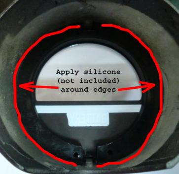
3 BEFORE YOU BEGIN: Read these instructions completely. Plan out your wiring scheme ahead of time. Use the included wiring diagrams to help guide your wire routing Use 14 ga. wire on all connections to sending units. Use electrical solder and heat shrink tubing or appropriate solder less connectors to make all wiring connections Disconnect the vehicle's battery Do not use thread sealer on the sending units, they have a tapered thread Have a plan. Mock up parts or layout as needed. It takes a little more time, but will save time and money in the end. Recommended Tools and Materials Needed for Installation Silicone sealer/adhesive 14 and 16 ga. stranded wire Spade or Bullet connectors Momentary push-button Pressure sender for hour meter Electrical solder (optional) Heat shrink tubing (optional) Soldering iron (optional) Measuring tape or ruler Engine adaptors for senders Wire cutters Wire stripper/crimper Files Various hand tools: wrenches, screwdriver, etc Wiring the gauges: Run the power wiring from the gauges to an appropriate positive (+) on the fuse block after the battery. This applies to the switched 12V+ and gauge lighting Connect the ground to a good dedicated ground on the chassis Run each wire to the appropriate sender and use the proper connector for each item (eyelet, spade, etc.) from the sender to the dash. Leave some extra slack in the wire and label it. Ensure that wires will not chafe on holes by using grommets and that they will clear any moving objects. Once wires are run from the appropriate sender location to the gauges location, connect to the corresponding wire on the Packard connector with solder and heat shrink tubing or a solder less connector. Sender installation You must use senders with the proper ohm match for your gauge, using mis-matched senders will result in improper readings on your gauge. Water temperature ohm The water temperature sender has a 1/8 NPT end. It should be installed close to the thermostat on the intake manifold. There are usually ports for temperature on the block in the water jackets, which can be used as well. Oil pressure ohm The sender has a 1/8 NPT end on it. Check for your factory location for a pressure port and install. Fuel level This kit has several fuel level options, check your application for proper match before installing Original Chevy style : universal with sender 0-90 GM match Early 60s-late 80s Voltmeter The voltmater does not use a sender but picks up the voltage from the wiring harness (see wiring diagram)
4
5
6
7 TACHOMETER OPERATION Your tachometer is designed using the latest technology for years of trouble free, accurate service. Review the wiring diagram for proper operation and cylinder selection. CYLINDER SELECTION Cylinder Selection is accomplished by moving the jumper wire on the back of the cluster. See wiring diagram for cylinder selection jumper location. This cluster is pre-set to 8 cylinder at the factory. TACHOMETER SIGNAL This tachometer will function from any pulsed input from any signal source. General connections are as follows: Standard ignition systems: Connect input to negative (-) side of the coil CDI or ignition boxes: Connect to the tach output on box or follow manufacturer s instructions. PCM/ECU/Computer: Connect to tach signal output on box. On some outputs a very low output is used, a step-up resistor may be required see diagram below. LIGHTING AND INDICATOR LAMPS All Tri-Five clusters utilize LED lights for maximum brightness in the smallest package size. The lighting system is designed to operate on 12 V and no modifications are required. The LEDs are not dimmable using a standard rheostat. Use of an LED dimmer may be used or inline resistors. All turn signals, high beam and warning lamps are LEDs triggered and designed to operate on 12V + signal. In the event that any of them require a ground signal a relay may be used.
8 SPEEDOMETER OPERATION Your new speedometer features the latest in technology and advanced features for reliable operation, long service life and ease of installation. Read the entire operations manual before starting. SPEEDOMETER SIGNAL: This speedometer will function from any pulsed signal or waveform signal. This includes aftermarket speed senders, pulse generators, VSS, or any original equipment speed sender installed in the OE transmission. GPS speed senders will also operate the speedometer properly. SPEEDOMETER SUPPLEMENTAL Please review advanced speedometer functions in the back of this manual for further information on the speedometer. SETTING THE SPEEDOMETER Typically the speedometer is set using a drive a mile to calibrate function. Setting via drive a mile is as follows: Calibrate (Drive A Mile) Use the Drive A Mile function to calibrate the Speedometer. With the vehicle stopped and engine off, press the remote button while starting the engine. The display will show the SETUP menu after the self test is performed. A short press of the remote button will cycle display. Press again until the display shows the Drive a Mile calibration screen. A long push of the remote button will make the Speedometer go into the calibration mode. The screen will change and a group of numbers will be displayed and will flash. These numbers represent the current pulses per mile and will change after calibration. Press the remote button and the screen will change to the starting position. Drive a mile. Stop the vehicle. Press the remote button again. Restart engine. The Speedometer is calibrated.
9 The Speedometer has two modes NORMAL and SETUP. NORMAL operation has two functions, Trip and Odometer. The trip mode is initially set. To switch between them, momentarily press the external button. Trip trip Odometer OdO In the Odometer mode the displayed mileage is in miles. In Trip mode the displayed mileage is in tenths. Reset the Trip Odometer Hold the button down while the display is in TRIP mode, the display will show reset and will then show the trip mileage flashing. A short button push will reset the trip mileage to zero, and a long push will return to the ODO mode with no change. After the trip is cleared, a long push will return to ODO mode.
10 WIRING DIAGRAM -ALL TRI-FIVE KITS 12-PIN CONNECTOR GREEN/YELLOW OIL PRESSURE SENDER BATTERY IGNITION FUSE BLOCK YELLOW TEMPERATURE SENDER RED 22 GA L. TURN 12+ WHITE LED LIGHTING PARKING LAMP SWITCH LED LIGHTING WILL NOT DIM ON RHEOSTAT LED DIMMER MAY BE REQUIRED ORANGE SPEED SIGNAL INPUT BLACK GROUND RED 18 GA 12 V POWER GREEN 22 GA R. TURN 12V+ GREEN 18 GA FUEL SENDER BROWN SPEEDO SET BUTTON VIOLET TACH SIGNAL BLUE HIGH BEAM 12V+ MOMENTARY SWITCH FUEL LEVEL SENDER MUST MATCH GAUGE FACTORY GM 0-30 TYPICAL 2-WIRE SPEED SENDER, VSS, IN TRANS SENDER BLACK--TO CHASSIS GROUND SEPEARATE WIRE: GRAY RED WARNING LAMP (OPTIONAL) 12V+ CONNECT COMM PORT JUMPER TO PROPER CYL SELECTION COIL SIGNAL (-) SIDE OF COIL OR SIMILAR ECU OUTPUT 5V SQUARE WAVE SIGNAL CDI BOX TACH OUTPUT COMPUTER/PCM OUTPUT: USE A PULL UP RESISTOR TO AMPLIFY SIGNAL SEE BELOW: 12V POWER TO SPEED SIGNAL INPUT BLACK--TO CHASSIS GROUND RED-12V + SWITCHED WHITE OR GRAY-SPEED SIGNAL TO SPEEDOMETER INPUT WHITE OR GRAY-SPEED SIGNAL TO SPEEDOMETER INPUT COMM PORT 4 CYL 6 CYL 8 CYL RUN DIRECTLY TO SPEEDOMETER TACHOMETER CYLINDER SELECTION JUMPER ON BACK OF CLUSTER 10-K OHM 1/4 WATT RESISTOR TACH SIGNAL FROM COMPUTER PULL UP RESISTOR INSTALLATION PCM/COMPUTER OUTPUTS COMPUTER/PCM OUTPUT NOT USED ON 57 CLUSTER TYPICAL 3-WIRE SPEED SENDER
11 GENERAL GAUGE TROUBLESHOOTING Before you call, please check these items, they are sometimes obvious, but in the large scope of a build, sometimes can be missed. Double check grounds! Instruments operate on resistance to grounds. The connections should be secure, soldered if possible. Remember, no Teflon or sealant on senders. Senders have a tapered pipe thread and do not require sealant. Double check with the wiring diagrams. There are a lot of wires to hook up to a gauge set. GENERAL Gauge "sticks" Loosen nuts that attach the back clamps. This can sometimes pull on the housing enough to distort the dial and contact the pointer. Gauge inoperative/reading incorrectly Check for 12V at the gauge on the + and ground. Check for the correct resistance on the sender With power on, temporarily ground the sender lead, this will peg the gauge to its highest reading. TACHOMETER TROUBLESHOOTING Erratic reading: This is caused 99% of the time by a loose connection. Check spade or ring connectors. Sometimes these are connected well enough to work for a while, but do not hold up. Dead tach Caused by no power, or no signal. Check for power. Turn on ignition and watch the pointer, it should "jump" Reads too high/low: Usually this is caused by the incorrect # of cylinders on the back of the gauge. When using a magneto or alternator to drive the tach, an adjustment pot. Is behind the label at the 8:00 position on the rear of the gauge. SPEEDOMETER TROUBLESHOOTING Speedometer problems are very similar to tachometer issues. Check the obvious first, grounds, power, correct connections. What type of sender are you using? Check for pointer "jump" These refer to all speedometer problems from dead to will not calibrate. Most speedometer problems can be traced to a problem with the signal to the gauge. OE/Integrated sender test: Connect a multimeter on voltmeter function leads to ground and signal. Drive the vehicle. You should be getting an AC current of V. If it is below 3 volts the sender is defective or there is a waek connection. Another avenue to try is changing the signal input from L to N or H. This procedure is described under the SETUP section of this booklet. This is also a good way to remedy a "floating" pointer. When a pointer kind of roams but is not steady. This is usually from a weak signal to the speedometer. Another option is to directly ground the sender and apply a switched 12V+ source to the positive input side of the sender.
NEW VINTAGE INSTRUMENT AND GAUGE KIT INSTALLATION INSTRUCTIONS 3-1 INSTRUMENT KITS SPEEDO/TACH KITS REV
 NEW VINTAGE INSTRUMENT AND GAUGE KIT INSTALLATION INSTRUCTIONS 3-1 INSTRUMENT KITS SPEEDO/TACH KITS REV.01-032912 INDEX THE BASICS FUNCTIONS AND SENDERS TACHOMETER OPERATION SPEEDOMETER OPERATION TROUBLESHOOTING
NEW VINTAGE INSTRUMENT AND GAUGE KIT INSTALLATION INSTRUCTIONS 3-1 INSTRUMENT KITS SPEEDO/TACH KITS 3-3/8 STUDDED SPEEDOMETERS REV.
 NEW VINTAGE INSTRUMENT AND GAUGE KIT INSTALLATION INSTRUCTIONS 3-1 INSTRUMENT KITS SPEEDO/TACH KITS 3-3/8 STUDDED SPEEDOMETERS REV.02-091415 INDEX THE BASICS FUNCTIONS AND SENDERS TACHOMETER OPERATION
NEW VINTAGE INSTRUMENT AND GAUGE KIT INSTALLATION INSTRUCTIONS 3-1 INSTRUMENT KIT REV
 NEW VINTAGE INSTRUMENT AND GAUGE KIT INSTALLATION INSTRUCTIONS 3-1 INSTRUMENT KIT REV.02 07.11.11 INDEX THE BASICS FUNCTIONS AND SENDERS TACHOMETER OPERATION SPEEDOMETER OPERATION TROUBLESHOOTING WIRING
FULL SWEEP STEPPER MOTOR INSTRUMENT KIT INSTRUCTION MANUAL 1969,REDLINE, 2020 SERIES
 FULL SWEEP STEPPER MOTOR INSTRUMENT KIT INSTRUCTION MANUAL 1969,REDLINE, 2020 SERIES REVB071211 INDEX 3-3/8 PROGRAMMABLE SPEEDOMETER 3-3/8 TACHOMETER 2-1/16 GAUGES TEMPERATRURE SENDER PRESSURE SENDER PROGRAMMABLE
PHOENIX TACHOMETER WITH OLED DISPLAY
 PHOENIX TACHOMETER WITH OLED DISPLAY REV A0031418 PROGRAMMABLE TACHOMETER WIRING Standalone tachometers with AMP plugs are incandescent perimeter, backlit or LED backlit. Incandescent bulbs will be in
MECHANICAL SPEEDOMETER KITS
 MECHANCAL PEEDOMETER KT REV B 031518 MECHANAL PEEDOMETER Mechanical speedometers operate from a mechanical drive cable connected directly to the transmission or transfer case. The drive ratio is 1:1 and
NEW VINTAGE INSTRUMENT AND GAUGE KIT INSTALLATION INSTRUCTIONS GEN II BACKLIT INSTRUMENT KITS
 NEW VINTAGE INSTRUMENT AND GAUGE KIT INSTALLATION INSTRUCTIONS GEN II BACKLIT INSTRUMENT KITS REV.B-050818 INDEX THE BASICS MINOR GAUGES TACHOMETER OPERATION SPEEDOMETER OPERATION TROUBLESHOOTING pg. 2
Classic Instruments & 1956 Chevy. Installation Manual
 Classic Instruments 1955 & 1956 Chevy Installation Manual Table of Contents Welcome from the Team at Classic Instruments!... 3 Disassemble Original Gauge... 4 Assemble New Gauge Cluster... 5 Speedo, Tach,
Classic Instruments Corvette. Installation Manual
 Classic Instruments 1963 1967 Corvette Installation Manual Table of Contents Welcome from the Team at Classic Instruments!... 3 Mounting the Gauges... 4 Gauge Cluster Wiring... 6 Gauge Cluster Wiring Diagram...
Classic Instruments Cluster. Installation Manual
 Classic Instruments 6400 Cluster Installation Manual Table of Contents Welcome from the Team at Classic Instruments!... 3 Mount New Gauge Cluster... 4 Instrument Cluster Wiring... 5 Speedometer & Tachometer
Tach-Force Chevy Truck
 Classic Instruments Tach-Force 1955 1959 Chevy Truck Installation Manual Table of Contents Welcome from the Team at Classic Instruments!... 3 Mount New Gauge Cluster... 4 Instrument Cluster Wiring... 5
Chevy Truck
 Classic Instruments 1954 1955 Chevy Truck Installation Manual Table of Contents Welcome from the Team at Classic Instruments!... 3 Mounting Gauges... 4 4 5/8 Speedometer Wiring [no included tachometer]...
Classic Instruments Ford F100. Installation Manual
 Classic Instruments 1953 1955 Ford F100 Installation Manual Table of Contents Welcome from the Team at Classic Instruments!... 3 Mount New Gauge Cluster... 4 Instrument Cluster Wiring... 5 Speedometer
Classic Instruments Chevy. Installation Manual
 Classic Instruments 1957 Chevy Installation Manual Table of Contents Welcome from the Team at Classic Instruments!... 3 Mounting Gauges... 4 Speedo, Tach, Volt and Oil Pressure Gauge Wiring... 5 Speedo,
INSTALLATION GUIDE Multi-Gauge Set with sending units Part Number: M 9999
 Made in America Lifetime Guarantee Thank you for purchasing this instrument set from Intellitronix. We value our customers! INSTALLATION GUIDE Multi-Gauge Set with sending units Part Number: M 9999 * Always
INSTALLATION GUIDE Six Gauge Universal Digital Dash Panel Part Number: DP10002
 Made in America Lifetime Guarantee Thank you for purchasing this digital dash panel from Intellitronix. We value our customers! INSTALLATION GUIDE Six Gauge Universal Digital Dash Panel Part Number: DP10002
INSTALLATION GUIDE Ford Mustang Digital Dash Panel Part Number: DP7009 Year Series:
 Made in America Lifetime Guarantee Thank you for purchasing this gauge panel from Intellitronix. We value our customers! INSTALLATION GUIDE Ford Mustang Digital Dash Panel Part Number: DP7009 Year Series:
Classic Instruments Chevelle. Installation Manual
 Classic Instruments 1964 1965 Chevelle Installation Manual Table of Contents Welcome from the Team at Classic Instruments!... 3 Included Mounting Hardware... 4 Mounting Gauges... 5 Wiring Diagram... 6
INSTALLATION GUIDE Chevrolet Monte Carlo Dash Panel Part Number: DP9002 Year Series:
 Made in America Lifetime Guarantee Thank you for purchasing this instrument from Intellitronix. We value our customers! INSTALLATION GUIDE Chevrolet Monte Carlo Dash Panel Part Number: DP9002 Year Series:
Classic Instruments Ford. Installation Manual
 Classic Instruments 1940 Ford Installation Manual Table of Contents Welcome from the Team at Classic Instruments!... 3 Mount New Gauge Cluster... 4 Instrument Cluster Wiring... 5 Pulse Signal Generator
Part Number DP6003 Chevy Truck Digital Dash YEARS 67-72
 Part Number DP6003 Chevy Truck Digital Dash YEARS 67-72 KIT COMPONENTS: One (1) Digital Circuit Board One (1) Smoked Acrylic See-Through Lens *Peel off protective covering from both sides of lens attached
Chevy Truck
 Classic Instruments 1967 1972 Chevy Truck Installation Manual Table of Contents Welcome from the Team at Classic Instruments!... 3 Remove the Stock / OEM Instrument Panel... 4 Instrument Cluster Wiring...
Classic Instruments. Six Pack. Installation Manual
 Classic Instruments Six Pack Installation Manual Table of Contents Welcome from the Team at Classic Instruments!... 3 Universal, Shoebox & 61-66 F100 Gauge Mounting... 4 Bronc Package Gauge Mounting...
Classic Instruments Camaro. Installation Manual. Revised: January 6, 2015 Page 1
 Classic Instruments 1967 1968 Camaro Installation Manual Revised: January 6, 2015 Page 1 Contents Welcome from the Team at Classic Instruments!... 3 Remove Original Instrument Panel... 4 New Instrument
Chevy Truck
 Classic Instruments 1947 1953 Chevy Truck Installation Manual Table of Contents Welcome from the Team at Classic Instruments!... 3 Mounting Gauges... 4 4 5/8 Speedometer Wiring [no included tachometer]...
Thank you for purchasing this instrument from Intellitronix. We value our customers!
 Made in America Lifetime Guarantee Thank you for purchasing this instrument from Intellitronix. We value our customers! INSTALLATION GUIDE Corvette Digital Dash Panel Part Number: DP2003 Year Series: 1984-1989
Classic Instruments Chevy. Installation Manual
 Classic Instruments 1951 1952 Chevy Installation Manual Table of Contents Welcome from the Team at Classic Instruments!... 3 Included Mounting Hardware... 4 Mounting Gauges... 5 4 5/8 Speedometer Wiring
INSTALLATION GUIDE Chevrolet Digital Dash Panel Part Number: DP6002 Year Series:
 Made in America Lifetime Guarantee Thank you for purchasing this instrument panel from Intellitronix. We value our customers! INSTALLATION GUIDE Chevrolet Digital Dash Panel Part Number: DP6002 Year Series:
INSTALLATION GUIDE Chevrolet Impala/Caprice Digital Dash Panel Part Number: DP1208 Year Series: 1968
 Made in America Lifetime Guarantee Thank you for purchasing this instrument from Intellitronix. We value our customers! INSTALLATION GUIDE Chevrolet Impala/Caprice Digital Dash Panel Part Number: DP1208
Chevy Truck
 Classic Instruments 1964 1966 Chevy Truck Installation Manual Table of Contents Welcome from the Team at Classic Instruments!... 3 Gauge Mounting... 4 Gauge Cluster Wiring... 5 4 Wire Harness... 5 16 Wire
INSTALLATION GUIDE Chevrolet Digital Dash Panel Part Number: DP6003 Year Series:
 INSTALLATION GUIDE Chevrolet Digital Dash Panel Part Number: DP6003 Year Series: 1967-1972 * Disconnect the battery before attempting any electrical work on your vehicle. * KIT COMPONENTS One (1) Digital
Mustang. Installation Manual
 1967-1968 Mustang Installation Manual Table of Contents WELCOME FROM THE TEAM AT CLASSIC INSTRUMENTS!... 3 REMOVE THE ORIGINAL INSTRUMENT PANEL... 4 WIRING DIAGRAM... 6 WIRING THE NEW INSTRUMENT CLUSTER...
PHOENIX SPEEDOMETER INSTALLATION INSTRUCTIONS
 PHOENIX SPEEDOMETER INSTALLATION INSTRUCTIONS PHOENIX-IMI-1031418 NVU Phoenix platform speedometers offer features found in complete clusters, OE instrument systems and data loggers, all in a standalone
Chevy Truck
 Classic Instruments 1947 1953 Chevy Truck Installation Manual Table of Contents Welcome from the Team at Classic Instruments!... 3 Mounting Gauges... 4 4 5/8 Speedometer Wiring [no included tachometer]...
Chevy Truck
 Classic Instruments 1973 1987 Chevy Truck Installation Manual Table of Contents Welcome from the Team at Classic Instruments!... 3 Gauge Mounting... 4 Gauge Cluster Wiring... 6 Pulse Signal Generator [SN16]
Ford Mustang
 Classic Instruments 1965 1966 Ford Mustang Installation Manual Table of Contents Welcome from the Team at Classic Instruments!... 3 Mounting the Gauges... 4 3 3/8 Speedometer Wiring... 6 3 3/8 Speedometer
INSTALLATION GUIDE Chevrolet Digital Dash Panel Part Number: DP6004 Year Series:
 INSTALLATION GUIDE Chevrolet Digital Dash Panel Part Number: DP6004 Year Series: 1973-1987 * Disconnect the battery before attempting any electrical work on your vehicle. * KIT COMPONENTS Three (3) Digital
INSTALLATION GUIDE Chevrolet Digital Dash Panel Part Number: DP6002 YEAR SERIES:
 Intelligent Electronics INSTALLATION GUIDE Chevrolet Digital Dash Panel Part Number: DP6002 YEAR SERIES: 1964-1966 * Disconnect the battery before attempting any electrical work on your vehicle. * KIT
Ford Mustang. Installation Manual
 1965 1966 Ford Mustang Installation Manual TABLE OF CONTENTS Welcome from the Team at Classic Instruments! 3 Mounting Gauges in New Bezel 4 3 3/8 Speedometer Wiring 6 3 3/8 Speedometer Wiring Diagram 6
Classic Instruments. Ultimate Speedometer & Speed-Tachular. Installation Manual
 Classic Instruments Ultimate Speedometer & Speed-Tachular Installation Manual Table of Contents Welcome from the Team at Classic Instruments!... 3 Gauge Wiring... 4 Ultimate Speedometer Wiring Diagram...
UNIVERSAL GAUGE WIRE HARNESS
 2650-1797-00 UNIVERSAL GAUGE WIRE HARNESS For Installing Auto Meter Electric Speedometer, Tachometer, And Short Sweep Electric Oil Pressure, Water Temperature, Fuel Level, and Volt Meter Gauges. This harness
Classic Instruments Corvette. Installation Manual
 Classic Instruments 1963 1967 Corvette Installation Manual Table of Contents Welcome from the Team at Classic Instruments!... 3 Mounting the Gauges... 4 Gauge Cluster Wiring... 6 Gauge Cluster Wiring Diagram...
Classic Instruments. Belera. Installation Manual
 Classic Instruments Belera Installation Manual Table of Contents Welcome from the Team at Classic Instruments!... 3 Optional Gear Indicator Mounting... 4 Gauge Mounting... 6 Gauge Cluster Wiring... 8 Gauge
MCL-30K-SPD IMPORTANT NOTE!
 MCL-30K-SPD Thank you for purchasing the Dakota Digital MCL-30K-SPD gauge for your Harley Davidson Touring bike. This is designed to be a replacement for all touring models from 1996 2003. This is part
MODEL HLY-2001 rev. B TANK MOUNT SPEEDOMETER/TACHOMETER INFORMATION SYSTEM
 MODEL HLY-2001 rev. B TANK MOUNT SPEEDOMETER/TACHOMETER INFORMATION SYSTEM Please read this before beginning installation or wiring. POWER Connect the red wire from the main harness to accessory power
Replace light bulb with the same number bulb as the one removed. White Wire: Connect to +12 Volt Lighting
 INSTALLATION INSTRUCTIONS SHORT SWEEP ELECTRIC GAUGES 2650-1079-00 Rev. C CAUTION FOR ALL GAUGE INSTALLATION (AMMETERS EXCLUDED) As a safety precaution, the +12V wire attached to the positive I (+) terminal
MODEL MCV-7000 series SPEEDOMETER/TACHOMETER INFORMATION GAUGE Please read this before beginning installation or wiring.
 MODEL MCV-7000 series SPEEDOMETER/TACHOMETER INFORMATION GAUGE Please read this before beginning installation or wiring. IMPORTANT NOTE! This gauge has an odometer preset option that is only available
CONTROL BOX. Wiring the control box into the vehicle. +12V
 CONTROL BOX Once the display panel is in place, mount the control box within the connecting cable's distance (approximately 3 feet) and secure to the underside of the dashboard. This case does not have
Mustang. Installation Manual
 1967-1968 Mustang Installation Manual I Table of Contents TABLE OF CONTENTS... II WELCOME TO THE TEAM OF CLASSIC INSTRUMENTS!... III REMOVE ORIGINAL INSTRUMENT PANEL... 1 DETERMINE SPEEDOMETER SIGNAL...
HLY-3015 MINI SPEED/TACH INFORMATION SYSTEM (weather and vibration resistant for exposed environments)
") HLY-3015 MINI SPEED/TACH INFORMATION SYSTEM (weather and vibration resistant for exposed environments) Neutral Left turn Low voltage Right turn High beam Engine Low oil *To avoid damage to motorcycle,
HLY-3015 MINI SPEED/TACH INFORMATION SYSTEM (weather and vibration resistant for exposed environments) Neutral Left turn Low voltage Right turn High beam Engine Low oil *To avoid damage to motorcycle,
ION-01-6 PERFORMANCE SPEEDOMETER/TACHOMETER COMBO
 ION-01-6 PERFORMANCE SPEEDOMETER/TACHOMETER COMBO MOUNTING: It should be inserted into the opening from the front and the L-clamps will be installed from the back. Tighten the nuts on the L-clamps so that
Replace light bulb with the same number bulb as the one removed. White Wire: Connect to +12 Volt Lighting
 INSTALLATION INSTRUCTIONS SHORT SWEEP ELECTRIC GAUGES 2650-1079-00 Rev. C CAUTION FOR ALL GAUGE INSTALLATION (AMMETERS EXCLUDED) As a safety precaution, the +12V wire attached to the positive I (+) terminal
Mustang. Installation Manual. Revision 11/16/10
 1967-1968 Mustang Installation Manual Revision 11/16/10 I Table of Contents TABLE OF CONTENTS...II WELCOME TO THE TEAM OF CLASSIC INSTRUMENTS!... III REMOVE ORIGINAL INSTRUMENT PANEL...1 DETERMINE SPEEDOMETER
Chevrolet. Installation Manual
 1959 1960 Chevrolet Installation Manual TABLE OF CONTENTS Welcome from the Team at Classic Instruments!... 3 Mount Adapter Ring... 4 Mount New 4-5/8 Gauge in Center Gauge Pod... 4 Mount New 2-1/8 Gauges
Classic Instruments. Installation Manual. Revised: July 23,
 Classic Instruments Installation Manual Revised: July 23, 2018 1 Table of Contents Speedometer Installation... 4 Speedometer Wiring... 4 16-Pulse GM / Chrysler Signal Generator [SN16]... 5 Ford Signal
Series II ODYR/SLX-01-1-C PERFORMANCE SPEEDOMETER
 Series II ODYR/SLX-01-1-C PERFORMANCE SPEEDOMETER MOUNTING: The gauge requires a round hole 3-3/8 in diameter. It should be inserted into the opening from the front and the U-clamp will be installed from
HLY-3016 PERFORMANCE SPEEDOMETER/TACHOMETER COMBO (weather and vibration resistant for exposed environments)
") HLY-3016 PERFORMANCE SPEEDOMETER/TACHOMETER COMBO (weather and vibration resistant for exposed environments) *To avoid damage to motorcycle, please see Speedometer, Tachometer, and Status and Warning Indicators
HLY-3016 PERFORMANCE SPEEDOMETER/TACHOMETER COMBO (weather and vibration resistant for exposed environments) *To avoid damage to motorcycle, please see Speedometer, Tachometer, and Status and Warning Indicators
VACUUM FLUORESCENT DIGITAL DASHBOARD. The latest in digital dashboard technology for the street rodder, car, and truck enthusiast.
 SERIES 3 VACUUM FLUORESCENT DIGITAL DASHBOARD The latest in digital dashboard technology for the street rodder, car, and truck enthusiast. INSTALLATION AND OPERATION MANUAL Please read this before beginning
CUSTOM INSTRUMENT KIT INSTALLATION INSTRUCTIONS
 CUSTOM INSTRUMENT KIT INSTALLATION INSTRUCTIONS REV 1 01.3019 Advanced feature speedometers offer features found in complete clusters, OE instrument systems and data loggers, all in a standalone unit.
MODEL MCL-2002 TANK MOUNT SPEEDOMETER/TACHOMETER
 MODEL MCL-2002 TANK MOUNT SPEEDOMETER/TACHOMETER *To avoid damage to motorcycle, please see Speedometer, Tachometer, and Status and Warning Indicators sections for details on locating VSS, Tachometer,
MCL-5100, 5200, & 5400 Bar mount digital speedometer with indicators.
 MCL-5100, 5200, & 5400 Bar mount digital speedometer with indicators. *To avoid damage to motorcycle, please see Speedometer and Indicators sections for details on locating VSS and indicator wires for
DP10001 UNIVERSAL 5 GAUGE DIGITAL PANEL
 Nordskog Performance Products DP10001 UNIVERSAL 5 GAUGE DIGITAL PANEL **Before beginning the installation, read through these instructions thoroughly. Also, disconnect the positive battery cable to avoid
6 Gauge Box Set with Programmable Speedometer. Made in the USA. Caution. Speedometer Parts. Tachometer Parts. Fuel Level Gauge Parts.
 6 Gauge Box Set with Programmable Speedometer Caution Disconnect the battery during installation. Tighten nuts on the backclamp only slightly more than you can tighten with your fingers. Six inch-pounds
MODEL MCL-2002 TANK MOUNT SPEEDOMETER/TACHOMETER
 MODEL MCL-2002 TANK MOUNT SPEEDOMETER/TACHOMETER *To avoid damage to motorcycle, please see Speedometer, Tachometer, and Status and Warning Indicators sections for details on locating VSS, Tachometer,
Classic Instruments. Installation Manual
 Classic Instruments Installation Manual TABLE OF CONTENTS Welcome from the Team at Classic Instruments! 3 Mounting Gauges 4 4 Speedometer Wiring 5 4 Speedometer Wiring Diagram 5 16 Pulse Signal Generator
Full Sweep Minor Gauge Wiring:
 Full Sweep Minor Gauge Wiring: Notes on Senders: Temp Hi match/vdo 150C: Normally used in Oil temp, 140 280F. Temp Low match/vdo120c: Normally used in water temp, 100 240F. To test the gauges work (oil,
MODEL MVX-2011 TANK MOUNT SPEEDOMETER/TACHOMETER
 MODEL MVX-2011 TANK MOUNT SPEEDOMETER/TACHOMETER Wiring Diagram The MVX-2011 gauges will work on 2011-up Softail models with 5 gauges or 2012-up Dyna models with 5 gauges. It is a direct plug in on these
OMEGA KUSTOM INSTRUMENTS
 4O5O 6O 7O 8O 9O 1OO MPH 3O 1OO 2O Gauge Installation Manual 1O O OMEGA KUSTOM INSTRUMENTS 14O 12O 13O Operations Omega Kustom Gauges Speedometer: The speedometer can be set up to display MPH or KPH. There
Water Temperature. GM LS Engine Gauges Installation Guide
 2650-1563-00 GM LS Engine Gauges Installation Guide Water Temperature For water temperature, there is a port located on the right side (passenger side) of the engine, in the cylinder head, past the last
Switch select of sender types:
 Full sweep minor gauges wiring: B -------------------------------------------------- battery or +12V input. L -------------------------------------------------- LED illumination, for back lighting, dimmable.
REMOVAL OF FACTORY GAUGES ULTRA FLHT & FLHX
 MVX-8X04 gauge kit Thank you for purchasing the Dakota Digital MVX gauge kit for your Harley Davidson Touring bike. This kit is designed to be a direct plug in replacement for all touring models from 2004
Setup for using our speedometer with GPS sensor
 Setup for using our speedometer with GPS sensor Wiring: Speedometer red (1) power +12V Speedometer black (5) - ground Speedometer green (4) LED illumination (can be 12V) Speedometer blue (7) signal input,
REMOVAL OF FACTORY GAUGE ULTRA FLHT & FLHX (STREET GLIDE
 MCL-36K-SPD Thank you for purchasing the Dakota Digital MCL-36K-SPD gauge for your Harley Davidson Touring bike. This kit is designed to be a direct, plug in replacement for all touring models from 2004
VACUUM FLUORESCENT DIGITAL DASHBOARD. The latest in digital dashboard technology for the street rodder, car, and truck enthusiast.
 SERIES 3 VACUUM FLUORESCENT DIGITAL DASHBOARD The latest in digital dashboard technology for the street rodder, car, and truck enthusiast. INSTALLATION AND OPERATION MANUAL Please read this before beginning
MCL-3000 SERIES AIR PRESSURE PART# MCL-3K-A
 MCL-3000 SERIES AIR PRESSURE PART# MCL-3K-A Thank you for purchasing the Dakota Digital MCL-3K-A gauge for your Harley Davidson Touring bike. This gauge is designed to be a direct, plug in replacement
MODEL MCL-3212 SPEEDOMETER/TACHOMETER for 2012 up Dyna and Softail with 4 gauge
 MODEL MCL-3212 SPEEDOMETER/TACHOMETER for 2012 up Dyna and Softail with 4 gauge IMPORTANT NOTE! This gauge has an odometer preset option that is only available one time in the first 100 miles (160km) of
6 Gauge Box Set IS0333
 Caution 6 Gauge Box Set IS0 Rev. B ecr 882 9/202 Disconnect the battery during installation. Tighten nuts on the back clamp only slightly more than you can tighten with your fingers. Six inch-pounds of
Chevy INSTRUMENT CLUSTER CONNECTION KIT WIRING INFORMATION FOR A STOCK CHEVY CLUSTER GREY PINK S + FUEL TEMP S + LAMP LAMP HI BEAM
 WIRING INFORMATION FOR A STOCK 1955-56 CEVY CLUSTER 1955-56 Chevy Terminals and connectors are provided for installation to a stock 1955-56 dash cluster. Pigtail connections are provided for the instrument
MCL-30K-TCH. Remove nuts/screws and clamp to remove factory gauges 1 MAN#650336
 MCL-30K-TCH Thank you for purchasing the Dakota Digital MCL-30K-TCH gauge for your Harley Davidson Touring bike. This kit is designed to be a replacement for all touring models, from 1996 2003. This is
INSTRUCTIONS. 20 Circuit Wiring Kit Instructions October 2009, Speedway Motors, Inc.
 1 MAIN FUSE PANEL The main fuse panel harness s designed to be mounted under the dash a the firewall in an area close to the steering column. The enclosed representation of the main dash harness shows
Temperature Programming Quick Reference Guide
 Temperature Programming Quick Reference Guide Normal Mode Dial Brightness (press one at a time) Peak Mode Factory Default Reset (Hold for 5 seconds) High Alert Setting Mode Use LEFT or RIGHT buttons to
Mallory HyFire Electronic Ignition Control
 Mallory HyFire Electronic Ignition Control PN 690 Parts Included: 1 - Ignition 1 - Harness, Mag Pickup 1-18" Ground Wire 1-100V/1A Diode 4 - Mounting Screws WARNING: During installation, disconnect the
CMD-4000 SERIES REV. A 4+ FUNCTION REMOTE CONTROL DOOR LATCH OPENER SYSTEM INTRODUCTION
 CMD-4000 SERIES REV. A 4+ FUNCTION REMOTE CONTROL DOOR LATCH OPENER SYSTEM INTRODUCTION Thank you for purchasing the CMD-4000 series Remote Control Door Latch Opener System from Dakota Digital, Inc. This,
Classic Instruments SN74Z. Installation Manual
 Classic Instruments SN74Z Installation Manual Table of Contents Welcome from the Team at Classic Instruments!... 3 Before You Get Started... 4 Speedometer Application... 4 Connecting the SN74Z... 4 SN74Z
MODEL MCL /8 SPEEDOMETER/TACHOMETER for 2004 up
 MODEL MCL-3204 3-3/8 SPEEDOMETER/TACHOMETER for 2004 up IMPORTANT NOTE! This gauge has an odometer preset option that is only available one time in the first 100 miles (160km) of operation. See Odometer
ODY-01-1 or ODY-01-2 SPEEDOMETER
 ODY-01-1 or ODY-01-2 SPEEDOMETER Introduction: The Odyssey gauge series from Dakota Digital, Inc. incorporates the reliability and quality of our standard gauges, along with several unique features and
VACUUM FLUORESCENT DIGITAL DASHBOARD. The latest in digital dashboard technology for the street rodder, car, and truck enthusiast.
 SERIES 3 VACUUM FLUORESCENT DIGITAL DASHBOARD The latest in digital dashboard technology for the street rodder, car, and truck enthusiast. INSTALLATION AND OPERATION MANUAL Please read this before beginning
HDX. Analog / Digital Gauge System INSTALLATION AND OPERATION MANUAL. Please read this before beginning installation or wiring.
 HDX Analog / Digital Gauge System INSTALLATION AND OPERATION MANUAL Please read this before beginning installation or wiring. IMPORTANT NOTE! This system has an odometer preset option that is only available
jegs.com
 Contents Wiring Harness w/ Fuse Panel Installation Instructions Turn Signal Plug w/ Terminals 2 Headlight Plugs 3/4 Grommet 10 ¼ Terminals 4 Ring Terminals 10 Wire Ties Fusible Link 2 Screws & Nuts 2 Plastic
INSTRUCTIONS 12 Circuit Wiring Kit Instructions
 Fan 47 9 56 4 7 6 72 40 45 48 5 8 6 Gauge Power Temp Sender Headlight Power Power Radio Constant Power Instruments and Dash Rear of Vehicle Ignition and Lights Fuse Panel & Front of Vehicle Horn Alt Excitor
UTV-1000 Multi Gauge for Yamaha Rhino
 IMPORTANT NOTE! This gauge has an hour meter and odometer preset option available only for the first 1.0 engine hour and 10 miles (16km). See ODO/HR PRESET for instructions. UTV-1000 Multi Gauge for 2004-2006
UTV-1200 Multi Gauge for 2008 Yamaha Rhino
 IMPORTANT NOTE! This gauge has an hour meter and odometer preset option available only for the first 1.0 engine hour and 10 miles (16km). See ODO/HR PRESET for instructions. UTV-1200 Multi Gauge for 2008
Revised November 16, Classic Instruments. Installation Manual
 Classic Instruments Installation Manual I TABLE OF CONTENTS Speedometer Installation 1 Speedometer Wiring 1 16-Pulse GM / Chrysler Signal Generator [SN16] 2 Ford Signal Generator Adapter [SN17] 2 3 ⅜ Speedometer
SPEK PRO MONITOR AND CONTROL
 Programming Instructions for : Temperature 2 1/16 Spek Pro Racing Gauge - NASCAR ECU Compatible SPEK PRO MONITOR AND CONTROL Refer to the Flow Chart Programming Instructions while reviewing this guide.
CLASSIC UPDATE WIRING KIT
 by Randy Irwin 1955-57 CLASSIC UPDATE WIRING KIT Randy Irwin - Technical Writer Randy has been involved in the Chevy parts business for over 25 years. He is a wizard at creating, making and modifying custom
Mallory HyFire Electronic Ignition Control
 Mallory HyFire Electronic Ignition Control PN 690 Parts Included: 1 - Ignition 1 - Harness, Mag Pickup 1-18" Ground Wire 1-100V/1A Diode 4 - Mounting Screws WARNING: During installation, disconnect the
MSD 7AL-3, Ignition Control PN 7230
 MSD 7AL-3, Ignition Control PN 7230 Important: Read the instructions before attempting the installation. Parts Included: 1-7AL-3, PN 7230 1 - Parts bag (wires and connectors) 4 - RPM Modules 3000, 7000,
INSTALLATION INSTRUCTIONS MECHANICAL GAUGES
 1062650-1966-77 MECHANICAL GAUGES QUESTIONS: If after completely reading these instructions you have questions regarding the operation or installation of your instrument(s), please contact Hardin Marine
General Information. Installation Tips. Connections
 INSTALLATION INSTRUCTIONS ELITE DIGITAL SPEEDOMETER 2650-1951-77 Models 6789-CB, 6789-PH, 6789-SC, 6789-UL QUESTIONS: If after completely reading these instructions you have questions regarding the operation
SERIES 3 MODEL VFD3-92C-PU-U
 VACUUM FLUORESCENT DIGITAL DASHBOARD SERIES 3 NOW WITH SOLID STATE SENSOR TECHNOLOGY INSTALLATION AND OPERATION MANUAL MODEL VFD3-92C-PU-U 92-94 Chevrolet Full Size Pickup kit Please read this before beginning