EV Display User Guide
|
|
|
- Cordelia Fox
- 5 years ago
- Views:
Transcription


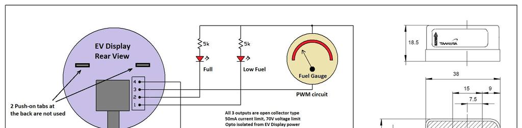
1 EV Display User Guide CleanPowerAuto LLC Brief Description: EV Display is designed to track battery state of charge and other related data in battery powered Electric Vehicle. EV Display is primarily designed for LiFePo4 battery, but can be used with any other battery if properly calibrated. Tracking state of charge requires a reference point when battery is considered full since EV Display can only assume what actual SOC is, based on initial setup parameters. SOC data will only be correct if current reading is correct and reference point is reached on the regular basis. Reference point can be full pack voltage or the fact that amount of full charge taken by the battery is always a little more than amount of discharge, to compensate of battery inefficiency. Display will be more accurate if the battery is fully charged on a regular basis. If battery is always partially charged then EV Display reading may drift long term and will become less reliable. Its recommended to do a full charge at least weekly. Specifications: - Nominal power voltage 12V. Min-Max voltage range 10-15V. Power circuit is isolated from pack voltage sensing circuit via internal DC-DC converter; allowing easy and safe installation in EVs with isolated high and low voltage systems. - Power current 30mA without LCD backlight and 60mA with LCD backlight. LCD backlight comes on when any button is pressed or current reading is non-zero and stays on for 60 minutes. - Hall Effect current sensor with max range of +/-1000Amp. Best accuracy is guaranteed in the range +/- 600Amp. Sensor can be installed anywhere in the battery current circuit, which passes both charge and discharge currents. Current reading resolution is 0.1A.
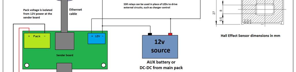
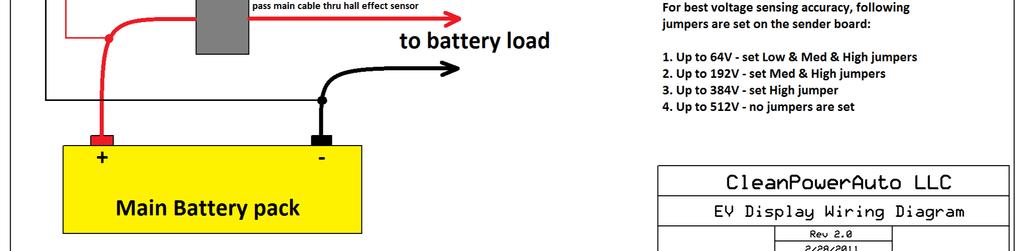
2 - Monitored battery capacity from 10AH to 2000AH, in 10AH increments. Configurable charge efficiency supports virtually any battery chemistry. - Sender unit and the Display are connected with standard CAT5e or CAT6 Ethernet cable. 7ft shielded cable is supplied. If you need longer cable, replace with high quality shielded Ethernet cable of appropriate length. Poor cable quality may have negative effect on Display s accuracy. - 3 opto-isolated output circuits, open collector type, 50mA max current and 70V max voltage. Binary outputs for Full and Low Fuel conditions, and PWM output for mechanical fuel gauge, can be used to drive OEM fuel gauges in existing vehicles. - Pack voltage sensing range 0-512V. Entire range is broken into 4 segments for best accuracy. Selection is made by jumpers on the sender board and corresponding software setting. Ranges are 0 64V 192V 384V 512V. - 2 lines LCD display shows any combination of 2 data points. Available data points are: Voltage, Amperage, AmpHours, SOC, Fuel Gauge, Temperature, Wattage, WattHours. - Display unit comes in a standard automotive 2 round gauge case, or square open board for custom mounting inside dash boards. Installation procedure: Display unit and sender unit are connected via shielded Ethernet cable. 7ft cable was supplied with your display, if you need longer cable you can buy it from any computer store. Make sure you get CAT5 or CAT6 high quality shielded cable to avoid high noise levels in EV. Display installs in a standard 2 gauge pod or appropriate size hole in the dash panel. You can also buy EV Display without the case, for custom install behind existing dash panels. NOTE: 2 push-on tabs at the back of the display case are not used for anything, leave them disconnected. Sender unit has a Hall Effect sensor and temperature sensor and must be mounted as close as possible to the battery pack to better reflect battery temperature. If you have insulated battery boxes, you should mount sender unit inside the battery box. Battery current must pass thru the hole of the Hall Effect sensor, so you must find a way to fit a bus bar thru the sensor s hole. It s possible to fabricate a custom bus bar to replace the standard bus bar which connects any 2 adjacent cells in your pack. Or you can use a piece of straight copper or aluminum stock between any 2 connection points in your battery loop and thread the hall effect sensor thru that stock. Here is an example of sender unit installed on a custom bus bar between 2 cells.

3 Once the sender unit is installed, connect 12V nominal power to the blue terminal on the sender unit. Watch for correct polarity. 12V power circuit must be always on, regardless of key switch position, since EV Display requires constant power source to keep track of battery SOC. You can power the unit from 12V aux battery or via DC-DC converter from the main pack, as long as DC-DC output is less than 15V and more than 10V. Connect pack voltage sensing wires to green terminal on the sender board. There is less than 1mA current going thru voltage sensing circuit, so you can use any size wires. NOTE: Be extra careful when working with pack voltage. For safety reasons, make wire connections at the sender board before connecting them to the battery pack. Make sure voltage sensing wires are safely routed and secured between the pack terminals and the sender board, so there is no chance of shorting them. Voltage sensing circuit is fused on the sender board, but you can also fuse it at the pack terminals for extra safety. Make sure bottom of the sender board is not touching any conducting surfaces; insulate the sender board if needed, to prevent any potential contacts between exposed areas of the sender board and nearby conducting surfaces or terminals. NOTE: If you are using EV Display to monitor 12V battery pack, such as marine or RV house bank, solar bank, etc., then you can connect power terminals and voltage sensing terminals in parallel, using single pair of wires going to the battery. Initial setup procedure: When EV Display is first powered on it will present all configurable parameters, so you can set appropriate values for your EV. Once setup is completed those values are stored in EEPROM so you don t have to reconfigure all values every time EV Display is power cycled. Press Left button to scroll thru the range of values, press Right button to lock the value and move to the next screen. Below is the listing of all setup screens and their descriptions.
4 This is initial calibration screen, it takes a few seconds to determine zero current levels, so current sensor can properly distinguish current direction and value. Its critical that EV Display is powered on when there is no current flowing thru the battery pack, its best to completely turn off ignition and make sure the charger is turned off or disconnected from EV. There is no input on this screen, just wait until it s done and it will move to the next screen on its own. Following setup parameters are available: V Range Voltage Range. Set this to match jumper configuration on the sender board. There are 4 available settings, to 64V, to 192V, to 384V, to 512V. For best voltage sensing accuracy use lowest range which covers the maximum voltage of your battery. For example, if your battery reaches max voltage of 156V at the end of charge, then use to 192V range setting. Sender board has a trimpot which is used for fine calibration of the voltage reading. PackSize - Battery pack capacity. Settings are from 10AH to 2000AH in 10AH increments. Full Vlt Full Voltage. Set this to the maximum voltage your battery reaches at the end of charge. This will be used to sync the display s 100% SoC reading when the battery reaches this preset level. If for any reason you are not connecting voltage sensing circuit to your battery, set this value to zero. If for any reason your display is not reporting correct voltage levels ( wrong jumper settings, wrong V Range setting, etc ) you must set this value to some high level, up to maximum of 512V, so it will not interfere with display s SOC reading. Min SOC Minimal State Of Charge. This percentage value sets Empty Fuel Tank level, so the driver can go by Fuel Gauge reading and not completely deplete the battery, to preserve its lifecycles. For example, if this value is set to 20%, then Fuel Gauge will report 0% when SoC is still at 20%. If you desire to use your battery to its full capacity and/or want Fuel Gauge to reflect true SoC, then set this value to zero. CurrDir Current Direction. Hall Effect sensor reports direction of DC current passing thru the sensor. Its important for correct EV Display functionality that current is sensed in correct direction for charge/discharge. If you installed the sender board and then realized that its reporting wrong direction of the current, then flip this value to avoid having to reinstall the sender board. Current should be reporting with + sign during charge and without any signs during discharge. TempComp Temperature Compensation. At low temperatures batteries cannot supply their entire capacity due to slowdown of electrochemical processes. This percentage value reduces Fuel Gauge reading based on temperature drop, linearly from 25C to 0C and below, such that Fuel Gauge reduction is equal this value at 0C ( freezing point ). For example, if you set this to 10% (recommended value for LiFePO4 cells), then Fuel Gauge will report 10% less
5 capacity at 0C, linearly changing across wide temp range. This value only effects Fuel Gauge reading, SOC reading still remains true to battery capacity regardless of the temperature. NOTE: For this feature to work properly, mount the sender board as close to your cells as possible. If your cells are insulated, mount the sender board inside the battery box, so temp sensor at the sender board closely reflects cell s temperature. Low Fuel Low Fuel level. This percentage value determines the minimal Fuel Gauge level at which Low Fuel circuit is triggered. This is used for external signaling, such as OEM dash boards, etc. TempUnit Temperature Units. Set this to Fahrenheit ( F ) or Celsius ( C ). ChargeEff Charge Efficiency. This percentage value slows down rate of SoC climb during the charge, to compensate for battery losses during discharge. Recommended setting for LiFePO4 cells is 98%. This would be much less for Lead Acid batteries, depending on their Peukert value and battery application. For example, in EVs with high C rates, Peukert effect is more pronounced, so this value must be set lower to more accurately report SoC and Fuel Gauge values during partial charges. This setting must be tuned experimentally for best accuracy. Ideal setting will cause SOC to reach 100% at approximately the same time as charger is finishing up the full charge. NOTE: This feature assumes that Pack Size is set to actual useful capacity of the battery at high C rates, which is almost true for LiFePO4 cells, but not for Lead Acid batteries. Lead Acid battery will have smaller useful capacity than its rated capacity, so Pack Size should be set to useful capacity, so EV Display can reflect meaningful Fuel Gauge. DeadZone Dead Zone. In some cases when temperature fluctuations are wide and fast, EV Display might show non-zero current reading when not expected. This is due to imperfect temperature stability of Hall Effect sensors. EV Display software compensates for this, but in some extreme situations it might not work 100%, resulting in small current reading when not expected. Dead Zone allows ignoring small current readings when they are likely false (when small reading starts after zero reading). During charge, when current is dropping during CV phase, EV Display will count it even in the Dead Zone. If small reading persists for over 60 minutes, it will be considered as false reading and will be ignored. You can turn off this feature by setting this value to zero. Default 0.3A is recommended for best zero reading stability. TestMode Test Mode is designed for verification of external circuits. If you connect external mechanical fuel gauge, driven by EV Display s PWM output, you can use test mode to make sure external gauge correctly follows EV Display s Fuel Gauge values. You can also test Full and Low Fuel circuits using test mode. In test mode, SOC and Fuel Gauge values will automatically
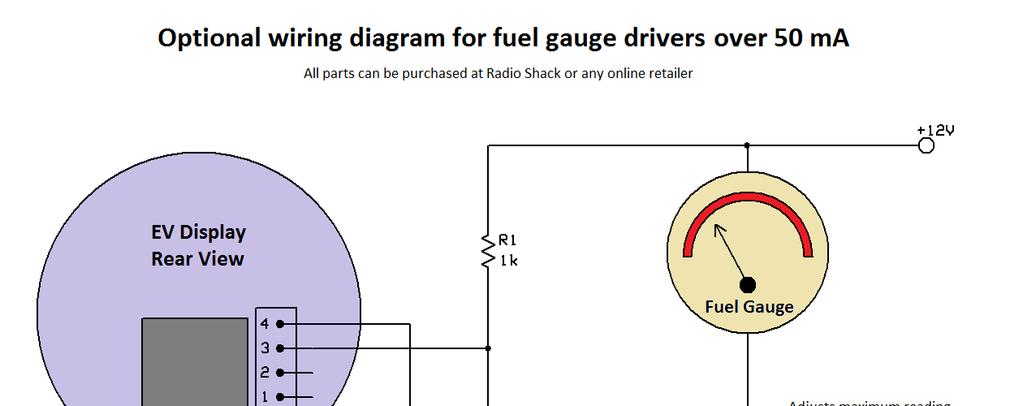
6 swing back and forth from 0 to 100% with 1% increments every second. Once you tested external circuits, repeat the setup routine and set this mode to Off. PWM Mode Allows you to select from 4 different PWM frequencies and pick appropriate signal phase. Some mechanical fuel gauges work better at low PWM frequencies and some may work better at higher frequencies. You can pick from 4000Hz, 500Hz, 125Hz, 31Hz. You can also select P for positive or N for negative PWM phase. This can be useful if you need to amplify PWM signal using a transistor, which inverts the signal. See optional wiring diagram at the end of this guide. This setting only applies to PWM fuel gauge output. If you are not using such output, you can leave this setting at any value, as it has no bearing on display functions. NOTE: Some mechanical gauges may sing at the PWM frequency, i.e. produce audible sound. You can try different frequencies or add some RC filtering to your gauge driver circuit to reduce singing. Using EV Display. EV Display has the 2 line LCD screen, capable of showing 2 pieces of data independently. Press Left button to scroll thru available data on upper line, press Right button to scroll thru available data on the lower line. Any combination of data is possible on 2 lines. Following list explains all available data counters: Ah remaining AmpHour capacity of the battery. When EV Display is initially powered, it will show full capacity, 100% SoC and 100 Fuel Gauge. To sync the battery with EV Display, make sure the battery is fully charged after display is powered up. AmpHour capacity will not go over its preset max value even if the battery is still charging, which allows for top sync procedure Wh remaining WattHour capacity of the battery. WattHour value is derived by multiplying AmpHour value and the Pack Voltage, so this value will be changing dynamically as voltage fluctuates with load. E F Graphical representation of the Fuel Gauge. Each of 6 bars corresponds to approximately 17% of capacity. 100% Fuel Digital Fuel gauge. 100% SoC State Of Charge A Instant current reading. + sign in front of the value indicates charge current. No sign indicates discharge current W Instant Wattage reading. This power value is derived by multiplying instant current and voltage. This is useful to estimate how much instant power is passing thru the battery
7 circuit. In EVs, this value at certain preset driving conditions can be used to determine EV s efficiency compared to other EVs at the same driving conditions. 123 V Pk Instant voltage reading. 25C Tmp Instant temperature reading at the sender board location. Zero Point calibration: Since Hall Effect sensor is a bidirectional device, its critical for correct EV Display functionality to maintain correct zero point, such that EV Display is showing zero amp reading when there is no current in the battery circuit. Initial calibration is done when EV Display is initially powered up. However, if initial calibration was wrong (current was flowing in the battery circuit during calibration), then it might be required to do another zero point calibration. Once you make sure there is no current in the battery circuit, press and hold both buttons on the EV Display for 5 seconds to begin calibration. Pack voltage calibration: EV Display is pre-calibrated to show correct voltage. However, if you made changes to jumper configuration on the sender board, or if EV Display shows slightly incorrect voltage compared to your trusted multimeter, you can adjust voltage reading using multi-turn trimpot located at the sender board. Slowly turn the trimpot with fine tip flat screwdriver and observe changes in the voltage reading on the EV Display until it matches with expected value. NOTE: Voltage calibration has very limited range. If your voltage reading is significantly different from actual battery voltage, then you likely have a mismatch between jumper settings and V Range software settings. Check your jumper settings and match V Range setting as follows: Low, Med & High jumpers set V Range up to 64V Med & High jumpers set V Range up to 192V High jumper set V Range up to 384V No jumpers set V Range up to 512V EV Display wiring diagram: Complete wiring diagram is shown on the next page. External connections are shown as simple examples to illustrate the functionality of output circuits. You can use external outputs in any way you want, as long as you stay within current/voltage specs, stated on the diagram ( 70V max and 50mA max, open collector output with negative common ). PWM circuit may require additional RC filtering to properly interface with your electromechanical fuel gauge. PWM frequency can be selected in the setup menu. Use the test mode to calibrate and test external outputs. Optional wiring diagram using MOSFET transistor is provided for fuel gauges which need more than 50mA operating current.
8
9
EV Display V4 User Guide
 EV Display V4 User Guide CleanPowerAuto LLC Brief Description: EV Display a.k.a SOC Gauge is designed to track battery state of charge and other related data in battery powered Electric Vehicle. EV Display
MiniBMS V3 User Manual
 MiniBMS V3 User Manual CleanPowerAuto LLC MiniBMS is a battery management system designed for LiFePo4 cells, used in Electric Vehicles. MiniBMS is designed to be reliable and cost effective solution; it
USER MANUAL MINI BMS DISTRIBUTED VERSION
 USER MANUAL MINI BMS DISTRIBUTED VERSION MiniBMS is a battery management system designed for LiFePo4 cells, used in Electric Vehicles. MiniBMS is designed to be reliable and cost effective solution; it
MiniBMS User Manual. Distributed version
 MiniBMS User Manual Distributed version MiniBMS is a battery management system designed for LiFePo4 cells, used in Electric Vehicles. MiniBMS is designed to be reliable and cost effective solution; it
βeta 20A AUTO 12V/24V SOLAR CHARGE CONTROLLER WITH REMOTE METER
 βeta 20A AUTO 12V/24V SOLAR CHARGE CONTROLLER WITH REMOTE METER USER MANUAL βeta 20A AUTO 12V/24V SOLAR CHARGE CONTROLLER WITH REMOTE METER (OPTIONAL) CHARACTERISTICS LCD display: all systems parameters
PSIM Tutorial. How to Use Lithium-Ion Battery Model
 PSIM Tutorial How to Use Lithium-Ion Battery Model - 1 - www.powersimtech.com This tutorial describes how to use the lithium-ion battery model. Some of the battery parameters can be obtained from manufacturer
Dual Voltage Solar Power Charge Controller Board Connection & Operation V2.xx
 Dual Voltage Solar Power Charge Controller Board Connection & Operation V2.xx Connection Instructions 1) Mount Board to a panel (Wood or Metal) using supplied spacers and screws. 2) Solar Start up 18 volts,
Instruction Manual. Duo-battery Solar Panel Controller EPIP20-DB series For Both 10 and 20 amp. Controllers (for use with solar panels only) + -
 + -") Instruction Manual Duo-battery Solar Panel Controller EPIP20-DB series For Both 10 and 20 amp. Controllers (for use with solar panels only) + - Optional - Switch to disconnect solar panel when engine alternator
Instruction Manual Duo-battery Solar Panel Controller EPIP20-DB series For Both 10 and 20 amp. Controllers (for use with solar panels only) + - Optional - Switch to disconnect solar panel when engine alternator
EV Power - A-Series 8 Cell, 16 Cell and 24Cell Chargers Installation & Usage Instructions.
 A-CHARGERS MANUAL 1.1 EV Power - A-Series 8 Cell, 16 Cell and 24Cell Chargers Installation & Usage Instructions. A-Series Charger Features - Simple to install and use, microprocessor control. - LiFePO4
TUTORIAL Lithium Ion Battery Model
 TUTORIAL Lithium Ion Battery Model October 2016 1 This tutorial describes how to use the lithium ion battery model. Some battery model parameters can be obtained from manufacturer datasheets, while others
Sól Dual Voltage Buck Boost Solar Charge Controller Connection & Operation V1.00
 Sól Dual Voltage Buck Boost Solar Charge Controller Connection & Operation V1.00 Connection Instructions Remove Bottom 4 cover to attach wires to terminal blocks then attach cover and flip over for mounting
MAGPOWR Spyder-Plus-S1 Tension Control
 MAGPOWR TENSION CONTROL MAGPOWR Spyder-Plus-S1 Tension Control Instruction Manual Figure 1 EN MI 850A351 1 A COPYRIGHT All of the information herein is the exclusive proprietary property of Maxcess International,
Battery Beak User Manual
 Battery Beak User Manual Rev 1.0 Cross the Road Electronics, LLC www.crosstheroadelectronics.com Cross The Road Electronics, LLC Page 1 11/30/2011 Device Overview Lanyard loop for included lanyard. Tough
123\SmartBMS. 123\SmartBMS manual V1.3. Albertronic BV The Netherlands
 123\SmartBMS 123\SmartBMS manual V1.3 Index Introduction... 2 Keep the batteries in perfect condition... 3 Package contents... 4 Specifications... 4 Placing the cell modules... 5 Mounting the IN Module...
VC-4820 Programmable DC-DC Converter with Battery Charger function USER'S MANUAL
 1. INTRODUCTION VC-4820 Programmable DC-DC Converter with Battery Charger function USER'S MANUAL This MCU controlled Step Down DC-DC Converter has a digitally adjustable output in 0.2V increments. This
SimpliPhi Power PHI Battery
 Power. On Your Terms. SimpliPhi Power PHI Battery INTEGRATION GUIDE: VICTRON Optimized Energy Storage & Management for Residential & Commercial Applications Utilizing Efficient, Safe, Non-Toxic, Energy
Orion 2 BMS Operation Manual
 www.orionbms.com Orion 2 BMS Operation Manual The Orion BMS 2 by Ewert Energy Systems is the second generation of the Orion BMS. The Orion BMS 2 is designed to manage and protect Lithium ion battery packs
User manual. BMS123 Smart
 User manual BMS123 Smart Introduction After the introduction of affordable LiFePO4 batteries, off-grid solutions became feasible. It is vital that such batteries are charged very carefully. In other words,
Turnigy FATBOY 8. User s Guide. Copyright 2012 Hobby King 01/18/2012
 Turnigy FATBOY 8 User s Guide Copyright 2012 Hobby King 01/18/2012 This Turnigy product manufactured in Singapore by LEO Energy Pte Ltd, www.revolectrix.com Contents Contents... 2 About FATBOY 8... 4 Using
HousePower BMS. CleanPowerAuto LLC
 HousePower BMS CleanPowerAuto LLC Features: Designed for 12V and 24V LiFePo4 battery banks, replacing Lead Acid house banks in marine and RV applications, with minimal changes to existing systems and wiring
Duo Battery Charge Controller
 Duo Battery Charge Controller RENOGY 10A 20A Pulse Width Modulation Solar Charge Controller Manual 1 2775 E. Philadelphia St., Ontario CA 91761 1-800-330-8678 Version: 1.2 Important Safety Instructions
Installation and Maintenance Instructions. World Leader in Modular Torque Limiters. PTM-4 Load Monitor
 World Leader in Modular Torque Limiters Installation and Maintenance Instructions PTM-4 Load Monitor 1304 Twin Oaks Street Wichita Falls, Texas 76302 (940) 723-7800 Fax: (940) 723-7888 E-mail: sales@brunelcorp.com
VC-30 / VC-40 Programmable DC-DC Converter with Battery Charger function USER'S MANUAL
 1. INTRODUCTION VC-30 / VC-40 Programmable DC-DC Converter with Battery Charger function USER'S MANUAL This MCU controlled Step Down 24V to 12V DC-DC Converter has a programmable 12.0 to 15.0V output in
LTX RF LEVEL SENSOR. Instruction Manual
 LTX RF LEVEL SENSOR Instruction Manual FOR MODELS LTX01, LTX02, LTX05 Intempco Document No: LTX - M01 Rev. 1 Issue Date: April 2005 LTX01 RF LEVEL SENSOR USER MANUAL Software Rev : Rev. Date : June 2004
Owner s Manual. MG2000 Speedometer IS0211. for use with SmartCraft Tachometer
 Owner s Manual MG2000 Speedometer for use with SmartCraft Tachometer IS0211 rev. E ecr#6395 08/2006 4/5/05 Changes 12/21 Index Description Available Functions for display page 1 Default Screens page 1
Rover Series. Rover 20A 40A Maximum Power Point Tracking Solar Charge Controller
 Rover Series Rover 20A 40A Maximum Power Point Tracking Solar Charge Controller 0 2775 E. Philadelphia St., Ontario, CA 91761 1-800-330-8678 Version 1.5 Important Safety Instructions Please save these
IMPORTANT. Always connect the batteries first. Use for 12V battery system only 12V (36 cells) solar panel array.
 solar panel array.") EN Appendix Manual IMPORTANT Always connect the batteries first. Use for 12V battery system only 12V (36 cells) solar panel array. Use for 24V battery system only 24V (72 cells) solar panel array. BlueSolar
EN Appendix Manual IMPORTANT Always connect the batteries first. Use for 12V battery system only 12V (36 cells) solar panel array. Use for 24V battery system only 24V (72 cells) solar panel array. BlueSolar
Mash Tun / RIMS Tube Controller
 Mash Tun / RIMS Tube Controller 1 Your new mash tun / RIMS Tube controller Thanks for buying your controller from us!!! Your controller is based on the MYPIN TA4 series PID controller. Unlike cheap REX
Operating and programming instructions at =AMPS or =WATTS REPLACED PERCENTAGE FROM LAST DISCHARGE
 TM-2030 TriMetric Battery Monitor Installation and User Guide TM 2030-RV Bogart Engineering CHARGING BATTERY REMINDERS when flashing-meets "CHARGED" criteria =TIME TO CHARGE =TIME FULL TO EQUALIZE =BATT.
MANUAL TROUBLESHOOTING. ECM Motor. ECM / ECM-DX Series. v100 Issue Date: 08/15/ Price Industries Limited. All rights reserved.
 MANUAL ECM Motor ECM / ECM-DX Series v100 Issue Date: 08/15/17 2017 Price Industries Limited. All rights reserved. ECM MOTOR TABLE OF CONTENTS ECM Motor Background...1 ECM Motor Power and Control Connectors...2
CONTROL BOX. Wiring the control box into the vehicle. +12V
 CONTROL BOX Once the display panel is in place, mount the control box within the connecting cable's distance (approximately 3 feet) and secure to the underside of the dashboard. This case does not have
Understanding The HA2500's Horiz Driver Test
 Understanding The HA2500's Horiz Driver Test Horizontal output stage symptoms and component failures are often caused by problems in the horizontal driver stage. The horizontal driver stage is seldom suspected,
G213V STEP MOTOR DRIVE REV 7: March 25, 2011
 Thank you for purchasing the G213V drive. The G213V is part of Geckodrive s new generation of CPLD-based microstep drives. It has short-circuit protection for the motor outputs, over-voltage and under-voltage
BMS16 v cell Lithium Battery Management System
 ZERO EMISSION VEHICLES AUSTRALIA http://www.zeva.com.au Safety Warning Although 8-16 cell lithium battery packs do not involve lethal voltages, they frequently involve dangerous amounts of current and
OPERATING INSTRUCTIONS
 Manual No LI-4159-MIL OPERATING INSTRUCTIONS OPERATING INSTRUCTIONS NAVY BATTERY CHARGER / ANALYZER P/N 4159-MIL MODEL CA-1550-MIL NSN: 4920-01-498-2543 Issued By: LamarTechnologies LLC 14900 40th Ave.
Installation and User Manual. with RAIN SENSOR.
 with RAIN SENSOR www.solarsmartopener.com Revision..0 TABLE OF CONTENTS Features In The Box Further Items Required Basic Operation Solar Panel and Operator Installation Operator Installation Solar Panel
REMOVAL OF FACTORY GAUGE ULTRA FLHT & FLHX (STREET GLIDE
 MCL-36K-SPD Thank you for purchasing the Dakota Digital MCL-36K-SPD gauge for your Harley Davidson Touring bike. This kit is designed to be a direct, plug in replacement for all touring models from 2004
CALL FOR A QUOTE (877)
") LiFePO4 Energy Storage Systems Overview POWERSYNC Lithium Iron Phosphate (LiFePO4) Energy Storage Systems (ESS) are designed for residential, commercial, or industrial scale projects where long lasting,
LiFePO4 Energy Storage Systems Overview POWERSYNC Lithium Iron Phosphate (LiFePO4) Energy Storage Systems (ESS) are designed for residential, commercial, or industrial scale projects where long lasting,
User Manual. BMS123 Smart
 User Manual BMS123 Smart Introduction After the introduction of affordable LiFePO4 batteries, off-grid solutions became available for wide public. It is vital that such batteries are charged very carefully.
PowerSTAR PS-2024-D. Maximum Power Point Tracking Solar Regulator. w w w. r o c s o l i d. c o m. a u. Contents
 w w w. r o c s o l i d. c o m. a u PowerSTAR PS-2024-D Maximum Power Point Tracking Solar Regulator Contents 1 Quick Start Guide... 2 2 Specifications... 3 2.1 General Operation... 3 2.2 Absolute Maximum
BMS-LiFePower. 123SmartBMS. Instruction manual
 BMS-LiFePower 123SmartBMS Instruction manual Index Introduction...2 Keep the batteries in perfect condition...2 Package contains (12 Volt, 4 cells)...3 Specs...3 Placing the cell modules...4 Mounting the
D2020N. Negative Ground 20A Max. Charge 20A Max. Load. Advanced Solar Charge Controller. DINGO User Guide. Read this before installing. Ver 1.
 D2020N Negative Ground 20A Max. Charge 20A Max. Load Advanced Solar Charge Controller DINGO User Guide Read this before installing Ver 1.5 031017 2 This is not an MPPT device: There is no voltage conversion.
PV Charge Controller SBC-7108 / 7112 / 7120
 PV Charge Controller SBC-7108 / 7112 / 7120 User's Manual NOTE: Please note that features like LCD read out of AH logging of 3 days (see Section 3.3) and 10 Night-light mode (see Section 4.3) are available
User Manual 123electric Battery Management System 123\BMS Revision 1.4 Augusts 2015
 User Manual 123electric Battery Management System 123\BMS Revision 1.4 Augusts 2015 Table of contents Introduction... 3 System structure... 3 Keep the batteries in a perfect condition : ALWAYS!... 5 Specifications...
SP PRO KACO Managed AC Coupling
 SP PRO KACO Managed AC Coupling Introduction The SP PRO KACO Managed AC Coupling provides a method of linking the KACO Powador xx00 and Powador xx02 series grid tie inverters to the SP PRO via the AC Load
User Manual Solar Charge Controller 3KW
 User Manual Solar Charge Controller 3KW Version: 1.3 CONTENTS 1 ABOUT THIS MANUAL... 1 1.1 Purpose... 1 1.2 Scope... 1 1.3 SAFETY INSTRUCTIONS... 1 2 INTRODUCTION... 2 2.1 Features... 2 2.2 Product Overview...
SAILMON SYSTEM LOAD CELL BOX MANUAL. Sailmon LoadCellBox Manual V1.0 Page 1
 SAILMON SYSTEM LOAD CELL BOX MANUAL Sailmon LoadCellBox Manual V1.0 Page 1 Sailmon LoadCellBox Manual V1.0 Page 2 CONTENTS 1. Product Description...4 2. Technical Specifications...5 3. Installation...6
Energy Storage. Lithium Batteries
 Energy Storage Lithium Batteries 48V 500AH Lithium Ion Battery Model : LIB S1 M1 4,246,935 The Smart Battery 48V 500AH Lithium Ion Battery features an automatic built in battery protection system (BPS)
TECHNICAL NOTE #4 Revised May 24, BOGART ENGINEERING Two Bar Road, Boulder Creek, CA (831)
") TECHNICAL NOTE #4 Revised May 24, 2004 BOGART ENGINEERING 19020 Two Bar Road, Boulder Creek, CA 95006 (831) 338-0616 TROUBLESHOOTING the TriMetric battery monitor Revised for the TM-2020 TriMetric What
TECHNICAL NOTE #4 Revised May 24, 2004 BOGART ENGINEERING 19020 Two Bar Road, Boulder Creek, CA 95006 (831) 338-0616 TROUBLESHOOTING the TriMetric battery monitor Revised for the TM-2020 TriMetric What
SP4 DOCUMENTATION. 1. SP4 Reference manual SP4 console.
 SP4 DOCUMENTATION 1. SP4 Reference manual.... 1 1.1. SP4 console... 1 1.2 Configuration... 3 1.3 SP4 I/O module.... 6 2. Dynamometer Installation... 7 2.1. Installation parts.... 8 2.2. Connectors and
MB A 12V/24V DC PROGRAMMABLE DUAL BATTERY ISOLATOR
 MB-3688 120A 12V/24V DC PROGRAMMABLE DUAL BATTERY ISOLATOR User Manual Warning and Precautions MB-3688 is built with corrosion resistant material and the main electronic assembly is well sealed inside
LEADING BATTERY ENERGY STORAGE SOLUTIONS AVAILABLE FROM FREEDOM WON (DATA SHEETS AVAILABLE UPON REQUEST) Freedom Lite Home & Business
 Freedom Lite Home & Business") Freedom Lite LEADING BATTERY ENERGY STORAGE SOLUTIONS AVAILABLE FROM FREEDOM WON (DATA SHEETS AVAILABLE UPON REQUEST) Freedom Lite & Business Residential and Small to Medium Businesses Lithium storage
Freedom Lite LEADING BATTERY ENERGY STORAGE SOLUTIONS AVAILABLE FROM FREEDOM WON (DATA SHEETS AVAILABLE UPON REQUEST) Freedom Lite & Business Residential and Small to Medium Businesses Lithium storage
Model 8000XL OPERATOR MANUAL
 Model 8000XL OPERATOR MANUAL DORAN SCALES, INC. 1315 PARAMOUNT PKWY. BATAVIA, IL 60510 1-800-262-6844 FAX: (630) 879-0073 http://www.doranscales.com MANUAL REVISION: 1.0 MAN0191 10/3/2005 INTRODUCTION
SPA MICROPROCESSOR 3 STAGE PROGRAMMABLE SHIFT LIGHT INSTALLATION AND OPERATING MANUAL PAGE 2...INSTRUMENT FEATURES. PAGE 3...OPERATING INSTRUCTIONS.
 SPA MICROPROCESSOR 3 STAGE PROGRAMMABLE SHIFT LIGHT INSTALLATION AND OPERATING MANUAL PAGE 2...INSTRUMENT FEATURES. PAGE 3...OPERATING INSTRUCTIONS. PAGE 4...MENU SYSTEM. PAGE 6...SPECIFICATIONS. PAGE
Manual Installation & Operation
 Manual Installation & Operation Model: NCxxLxx 12A or 30A Solid State Solar Charging Regulator and 12A Load Controller. 231 Patent #: 5,642,030 Applies Page 1 Warnings When Installing, connect grounds,
Lithium Power Pack LITHIUM-ION BATTERY SYSTEM. With epro Plus Battery Monitor
 Lithium Power Pack LITHIUM-ION BATTERY SYSTEM With epro Plus Battery Monitor LITHIUM-ION BATTERY SYSTEM After 2 years of research, testing and proving, and a further 5 years of infield sales, Enerdrive
Turbo30 OPERATING INSTRUCTIONS
 Turbo30 OPERATING INSTRUCTIONS ***WARNING*** It is dangerous to work in the vicinity of a lead-acid battery since they generate explosive gases during normal battery operation. To prevent an explosion
:43 1/13 Victron & BYD B-Box
 2018-11-04 15:43 1/13 Victron & BYD B-Box Victron & BYD B-Box The combination of Victron products with BYD B-Box lithium batteries (2.5, 5.0, 7.5, 10.0 and 12.8 models) has been tested and certified by
HP Series Smart Solar Charge Controller HP2430/2440/2450/2460 HP4830/4840 UserManual
 HP Series Smart Solar Charge Controller HP2430/2440/2450/2460 HP4830/4840 UserManual Dear users Thank you for choosing our product. Before using the product, please read this manual carefully.productfeatur
UTV-1000 Multi Gauge for Yamaha Rhino
 IMPORTANT NOTE! This gauge has an hour meter and odometer preset option available only for the first 1.0 engine hour and 10 miles (16km). See ODO/HR PRESET for instructions. UTV-1000 Multi Gauge for 2004-2006
UNIVERSAL CALIBRATOR M
 INTRODUCTION UNIVERSAL CALIBRATOR - 3001M Before going through the instruction manual for actual use of the instrument go through the specifications and take note of the following points carefully 1. No
Booma RC. Wallaby Switch.
 Booma RC Wallaby Switch www.boomarc.com 1 Congratulations for choosing the Booma RC Wallaby Switch. Wallaby Switch was designed for giant scale RC enthusiasts by giant scale RC enthusiasts. Wallaby Switch
The RCS-6V kit. Page of Contents. 1. This Book 1.1. Warning & safety What can I do with the RCS-kit? Tips 3
 The RCS-6V kit Page of Contents Page 1. This Book 1.1. Warning & safety 3 1.2. What can I do with the RCS-kit? 3 1.3. Tips 3 2. The principle of the system 2.1. How the load measurement system works 5
Instruction of Solar Charge Controller. User s Manual
 Instruction of Solar Charge Controller User s Manual 12V/24V 30A Dear Users: Thank you for selecting our product. Please read this manual carefully before you use this product. 0 The controller is for
BSR Magic Box Digital ignition control for 4, 6, or 8 cylinder engines
 BSR BSR Magic Box Digital ignition control for 4, 6, or 8 cylinder engines Features Digital Advance The main feature of the Magic Box is the digital advance that replaces conventional weights and springs.
Model: AEM14 Analog Engine Monitor
 Model: AEM14 Analog Engine Monitor Installation and Setup Manual Version 1 Table of Contents Monitor Overview DMK Engine Monitor Kit Section 1: Initial Setup 1.1 Internal Settings Switches Figure 1. AEM14
NEC Energy Solutions ALM 12V35 Batteries with
 NEC Energy Solutions ALM 12V35 Batteries with Charging Morningstar NEC Energy Solar Solutions Charge Controllers This application note was developed through a collaborative effort between NEC Energy Solutions
G203V / G213V MANUAL STEP MOTOR DRIVE
 G203V / G213V MANUAL STEP MOTOR DRIVE PRODUCT DIMENSIONS PHYSICAL AND ELECTRICAL RATINGS Minimum Maximum Units Supply Voltage 18 80 VDC Motor Current 0 7 A Power Dissipation 1 13 W Short Circuit Trip 10
RHINO MOTION CONTROLS
 Installation Manual and Datasheet http://www.rhinomotioncontrols.com Page 1 [] Key Features Smooth and quiet operation at all speeds and extremely low motor heating Industrial grade performance for 2-Phase
Elite Power Solutions Automatic Battery Control (ABC) Operation Manual
 Operation Manual") Elite Power Solutions Automatic Battery Control (ABC) Operation Manual Elite Power Solutions 335 E Warner Rd. STE 3 Chandler, AZ 85225 www.elitepowersolutions.com ABC Operation Manual Page 1 Table of Contents
Elite Power Solutions Automatic Battery Control (ABC) Operation Manual Elite Power Solutions 335 E Warner Rd. STE 3 Chandler, AZ 85225 www.elitepowersolutions.com ABC Operation Manual Page 1 Table of Contents
Model 1:8 Beast-ZTWSS120A 1:8 Beast-ZTWSS150A. PN#Model Cont.Current 120A 150A. Burst Current 760A 1080A
 Alien Power System BEAST Series Sensored/Sensorless Brushless ESC for 1:8 scale Car or Truck Thank you for purchasing the Alien Power System Brushless Electronic Speed Controller (ESC). The Alien Power
CruzPro. Volts Amps Amp-Hour Monitor VAH110. Other CruzPro Products. website:
 Other CruzPro Products l Depthsounders/w Keel Offset, Deep/Shallow/Anchor Drag Alarms l PC Based DSP Fishfinder for Windows98, NT, SE,XP, 2000 l Speed/Temperature/Logs l Digital DC Volts Gauge/w Alarms
The Traveler Series TM : Adventurer
 The Traveler Series TM : Adventurer 30A PWM Flush Mount Charge Controller w/ LCD Display 2775 E. Philadelphia St., Ontario, CA 91761 1-800-330-8678 Version: 3.4 Important Safety Instructions Please save
Open-circuit voltages (OCV) of various type cells:
 of various type cells:") Open-circuit voltages (OCV) of various type cells: Re-Chargeable cells: Lead Acid: 2.10V/cell to 1.95 NiMH and NiCd: 1.20 V/cell Li Ion: 3.60 V/cell Non-re-chargeable (primary) cells: Alkaline: 1.50 V/cell
Open-circuit voltages (OCV) of various type cells: Re-Chargeable cells: Lead Acid: 2.10V/cell to 1.95 NiMH and NiCd: 1.20 V/cell Li Ion: 3.60 V/cell Non-re-chargeable (primary) cells: Alkaline: 1.50 V/cell
PV Charge Controller SBC-6108 / 6112 / 6120 / 6130
 PV Charge Controller SBC-6108 / 6112 / 6120 / 6130 User's Manual Table of Contents Precautions and Specifications 1 1. Introduction 2 2. Control and Indicator 2 3. Installation and Indication 3 3.1 Connection
The Traveler Series: Adventurer
 The Traveler Series: Adventurer RENOGY 30A Flush Mount Charge Controller Manual 2775 E. Philadelphia St., Ontario, CA 91761 1-800-330-8678 Version: 2.2 Important Safety Instructions Please save these instructions.
Owner s Manual. Contents GP-PWM-10-SQ
 Owner s Manual Contents 1.0 Installation Overview... 2 2.0 Warnings... 2 3.0 Choosing a Location... 3 4.0 Installation Instructions... 3 5.0 Operating Instructions... 4 6.0 Frequently Asked Questions (FAQs)...
Low Frequency Inverter. User Manual
 Pure Sine Wave 220-240V 50-60Hz Low Frequency Inverter User Manual For LK/LW series Power Star inverters only, models: LK2000, LK2000-24, LK3000, LK3000-24, LK3000-48, LK6000-24, LK6000-48 1. Safety precautions
ENGLISH SAFETY INSTRUCTIONS. Recommendations for safe operation. Operator safety. General warnings
 Safety and use instructions LifeSpeed iq TM - 3-phase chargers ENGLISH SAFETY INSTRUCTIONS GOALS OF THIS MANUAL This manual is aimed at any authorized personnel wanting to use a 3-phase LifeSpeed iq TM
INSTRUCTIONS FOR TRI-METRIC BATTERY MONITOR May 8, 1996
 INSTRUCTIONS FOR TRI-METRIC BATTERY MONITOR May 8, 1996 PART 2: SUPPLEMENTARY INSTRUCTIONS FOR SEVEN TriMetric DATA MONITORING FUNCTIONS. A: Introduction B: Summary Description of the seven data monitoring
5001TCP SPEED CONTROLLER
 INSTALLATION AND SETTING UP MANUAL 5001TCP SPEED CONTROLLER WARNING Disconnect all incoming power before working on this equipment. Follow power lockout procedures. Use extreme caution around electrical
PWM Charge Controller with LCD Display 30A. User Manual
 PWM Charge Controller with LCD Display 30A User Manual 1 Product Features 1. 12V/ 24 V system voltages are automatically recognized. 2. Charging program options for sealed, GEL and flooded lead-acid batteries
How To Set Up SimpliPhi Batteries Using OutBack Chargers
 Introduction How To Set Up SimpliPhi Batteries Using OutBack Chargers The main focus of this application note will be on setting up OutBack charging sources for best operational performance for SimpliPhi
BMS SV 24S for 2S-24S LiPo, LiFe & LiTO&others Low power consumption High accuracy 2.8 TFT LCD display Programmable
 BMS SV 24S for 2S-24S LiPo, LiFe & LiTO&others Low power consumption High accuracy 2.8 TFT LCD display Programmable Thanks for your purchasing the for your vehicle. Read the ENTIRE instruction manual to
Do isolate the power supply from other high power systems such as Stereos and Alarms
 Thank you for purchasing a Smart Ride Air Management System, AIRBAGIT.COM s premier flagship product. This system will meet all of your custom and utility needs and will provide you years of trouble free
CPi. CoiL PACK IGNiTioN FOR AViATiON. For 4,6 and 8 cylinder 4 stroke applications. Please read the entire manual before beginning installation.
 1 CPi CoiL PACK IGNiTioN FOR AViATiON Coil pack (4 cylinder) Coil pack (6 cylinder) For 4,6 and 8 cylinder 4 stroke applications. Please read the entire manual before beginning installation. Software version
EV Power - Battery Control Unit Instructions. 8 Cell 24V
 EV Power - Battery Control Unit Instructions. 8 Cell 24V PAGE 1 OF 12 BCU-EVPPAK Features - Simple to install and use, microprocessor control. - Low power requirement, just 15mA when switched on with relay
Review: The West Mountain Radio CBA-IV Battery Analyzer Phil Salas AD5X. Figure 1: West Mountain Radio CBA-IV Battery Analyzer
 Review: The West Mountain Radio CBA-IV Battery Analyzer Phil Salas AD5X Figure 1: West Mountain Radio CBA-IV Battery Analyzer Introduction There has been more emphasis on battery power of late, particularly
Rev. U8e PL80e. Advanced PWM Solar Charge Controller. User Guide. Read this before installing. Solar Charge Controller
 Rev. U8e. 19092017 PL80e Advanced PWM Solar Charge Controller User Guide Read this before installing PL80e Solar Charge Controller 12-48V 80A Charge 40A Load PLASMATRONICS PLASMATRONICS 2 PL80e User Guide
Features: Enhanced throttle response, excellent acceleration, linearity and driveability
 120A/150A ESC X-Car 120A/150A Series Sensored/Sensorless Brushless ESC for 1:8 scale Car or Truck Thank you for purchasing the X-Car Brushless Electronic Speed Controller (ESC). The X-Car 1:8 Scale 120A/150A
Harness the Power of the Sun
 Harness the Power of the Sun Solar Controller / Battery Charger User s Manual Nominal Voltage: 12Volts Rated Solar Current: 30Amps / 40Amps Nominal Voltage: 12Volts / 24Volts Auto Rated Solar Current:
Operation and Installation Manual
 Operation and Installation Manual G-Scale Graphics 5860 Crooked Stick Dr. Windsor, CO 80550 970-581-3567 GScaleGraphics@comcast.net www.gscalegraphics.net Revision A: Updated 2/7/2018 Page Overview The
UTV-1200 Multi Gauge for 2008 Yamaha Rhino
 IMPORTANT NOTE! This gauge has an hour meter and odometer preset option available only for the first 1.0 engine hour and 10 miles (16km). See ODO/HR PRESET for instructions. UTV-1200 Multi Gauge for 2008
Instruction of Solar Charge Controller. User s Manual
 Instruction of Solar Charge Controller User s Manual 12V/24V 30A Dear Users: Thank you for selecting our product. Please read this manual carefully before you use this product. The controller is for off-grid
GS-100D+ Preconfigured Kits Manual
 100W 400W GS-100D+ Preconfigured Kits Manual Copyright 2012, Grape Solar, Inc. All Rights Reserved 1 2 Overview The GS-100D+Preconfigured Kits are designed to be modular and expandable solar generators,
5001TCP SPEED CONTROLLER
 VARIABLE SPEED DRIVE CONTROLLER INSTALLATION AND SETTING UP MANUAL 5001TCP SPEED CONTROLLER With PC101 Torque Limit Control WARNING Disconnect all incoming power before working on this equipment. Follow
Competition Electronics, Inc
 Competition Electronics, Inc Turbo35-GFX LiPo User s Manual Addendum 1 Introduction This enhancement makes it possible to charge 1,2 and 3 cell LiPo battery packs with the T35-GFX. Now you can have the
SOLAR LIGHTING CONTROLLER SUNLIGHT MODELS INCLUDED IN THIS MANUAL SL-10 SL-10-24V SL-20 SL-20-24V
 SOLAR LIGHTING CONTROLLER OPERATOR S MANUAL SUNLIGHT MODELS INCLUDED IN THIS MANUAL SL-10 SL-10-24V SL-20 SL-20-24V 10A / 12V 10A / 24V 20A / 12V 20A / 24V 1098 Washington Crossing Road Washington Crossing,
Model 7400 OPERATOR MANUAL
 Model 7400 OPERATOR MANUAL DORAN SCALES, INC. 1315 PARAMOUNT PKWY. BATAVIA, IL 60510 1-800-262-6844 FAX: (630) 879-0073 http://www.doranscales.com MANUAL REVISION: 1.0 MAN0198 10/3/2005 INTRODUCTION Introducing
Glow Plug for E Series Only
 Charging the Battery - Do not charge the battery, with a charger using negative discharge pulses, when connected to the ECU. This will destroy the electronics of the ECU. The only method is to disconnect