Owner s Manual. For SOLAR BOOM GATE. Model: CA-5000 SOLAR
|
|
|
- Abel Simmons
- 6 years ago
- Views:
Transcription
1 ECA Electronic Engineering Pty. LTD. Australia Tel: Fax: Owner s Manual For SOLAR BOOM GATE Model: CA-5000 SOLAR ( 2009 / Version 1 ) 1

2 1 Introduction 1.0 Control PCB Wiring INSTALLATION MANUAL for ECA Solar Boom Gate MODEL: CA Make sure to connect the positive terminal of the batteries to the RED wires and the BLACK wires to the negative terminal of the batteries. => Warranting! Wrong connection may cause damage to the battery Connect the solar panel s wire to the terminal J2. Solar Panel + Input - Anti-Crash sensor adjustment Battery Plug 2
3 Connections in the control panel Input / output LIGHT output STOP input OPEN input CLOSE input PHOTO SENSOR Input Description Normally Open and Common for switching ON and OFF the Photo Sensor during operation. Connect to N.C. push button and to GND to Stop the gate. Jumper this input to GRD if not in use. Connect to N.O. push button and to GND to Open the gate. Connect to N.O. push button and to GND to Close the gate. Connect to the Normally Close contacts of the photo sensor s relay. Jumper this terminal to GND if photo sensor has not been used, otherwise, the systems wouldn t operate. P.B.1 Input Connect to Normally Open Push Button to open and close the gate for manual operation. P.B.2 Input Connect to Normally Open Push Button or to the intercom system s relay (must be voltage free contacts) to operate the pedestrian mode to open 1m only. Ant. Input Antenna input. Connect to External Aerial Model ANT-433 for extending operation range. 3. Automatic SETUP - Setting the opening & closing time After installing the boom arm, the control panel must be set to learn the opening and closing cycle time as follows: Step 1. Put the gate on manual and open the gate to half open position and re-engage the gate back in gear. Step 2. Press and release Push Button TIMER on the control panel and the program LED will turn ON. Step 3. Press and release button ( I ) on the remote control and the set-up will begin. The gate will open and close twice and the control panel will set the opening and closing time; fast and slow time automatically. 4. Operation program The control panel has three options of programs that you can choose from, for operating the gate. Program No. 1 : Semi automatic Step By Step When choosing this type of operation, the gate will open, close or stop by the command of the remote control or the manual push button only (if connected). The first command opens the gate, the second stops, the third closes the gate, and the fourth stops the operation and so on. Program No. 2 : Automatic operation For automatic closure operation. When pressing the remote control, the gate will open and stay open for a preset time, after which the gate will close automatically Choosing the required operation program You can make your selection by the push button PROGRAM in the control panel, as follows: Step 1. Press and release Push Button PROGRAM on the control panel and the program LED will turn ON. Step 2. Choose and press; Button ( I ) on the remote control for operation program No. 1 Or Button ( II ) on the remote control for operation program No. 2 3
4 4.2. Setting the auto close timer This computerized control panel has a programmable auto-close timer that can be set very easily as follows: Step 1. Press and release Push Button TIMER on the control panel and the program LED will turn ON. Step 2. Press and release button (II) on the unit s remote control and the light relay and the program LED will start to flash. Step3. Wait the period of time you wish to set the Auto Close Time (for example 15 seconds) and then press and release button (II) on the remote control once again. The PROGRAM LED and the light relay will stop to flash, to indicate that the auto close delay time has been set for automatic operation. 5. Choosing the right ramp-down speed for the boom Arm The control panel allows you to select one out of four different speeds for the arm to slow down at the end of the travel and ramp-up. To select the right speed do as follows: 1. Press and release SPEED push button in the control panel and the program LED will turn ON. 2. Press button ( I ) on the Remote control for canceling the slow down speed. 3. Press button ( II ) on the Remote control for Medium High speed slow down => 90% 4. Press button ( III ) on the Remote control for Medium Low speed slow down => 80% 5. Press button ( IV ) on the Remote control for the Lowest Speed Slow down => 70% 6. Enable / Disable the Photo Sensor function in opening mode The control panel is responding to the photo sensor in closure mode, which will open the boom gate each time the photo sensor is triggered during closure time. However, you can set the control panel to respond to the photo senor also in the opening mode. In such a case, the boom gate will stop during opening, if the sensor is triggered. You can choose and define the photo sensor s function during opening mode, as follows: Step 1. Press and release Push Button FUNCTION on the PCB and the program LED will turn ON. Step 2. Press button ( II ) on the remote control to set the Photo Sensor to be active during opening mode too. If you wish the photo sensor to be active only in closing mode repeat step 1 & 2 above Photo Sensor Connection In order to minimize current consumption of the safety photo sensor, the Light Relay output in the control panel, is used to switch ON and OFF the photo sensor (if in use) during the operation of the motor. The light relay will turn ON the photo sensor only during the closure time of the boom gate and switch it OFF after the boom gate is fully closed. This will insure to minimize the current consumption of the photo sensor to zero when it is not in use. See connection diagram on next page. 4

5 Photo Sensor Rx N N C + - O C M Remove bridge when photo sensor is in use Photo Sensor Tx Solar Panel s Cable Red Black Setting and choosing features The control panel allows you to set four different functions and features according to your needs; 7.1. Setting the motor to be with or without Soft Start (ramp-up) The control panel is set to start opening and closing the boom gate with a soft start, however, you can choose to cancel this feature as follows: Step 1. Press and release Push Button FUNCTION on the PCB and the program LED will turn ON. Step 2. Press button ( III ) on the remote control to cancel the soft start. If you wish to restore this feature repeat step 1 & 2 above. 8. Anti-Crash sensor adjustment: The level of the Over-Load-Protection can be adjusted by the variable sensitivity pot on the control panel. To set the sensitivity level of the anti crash sensor do as follows: Step 1. Press the remote control to close the gate. Step 2. While closing, press with your hand against the gate to stop the gate from closing. If the gate stops with an unreasonable force, increase the sensitivity by turning the pot in the control panel to higher sensitivity level to get a satisfactory level of force. 5
6 9. Remote Control Teaching & Deleting the Memory The control panel s radio receiver can learn up to 160 remote controls into its memory. It can learn any of the buttons (I), (II) or (III) of the remote control (model TR-4RS) for operating the boom gate. Button (IV) is reserved for operating the boom gate partially, if required. There are two ways of teaching new remote controls: 9.1. Teaching remote controls from the control panel Press and release the REMOTE button in the control panel and the program LED light will start to flash indicating that the receiver is ready to learn the new remote control s button. Choose and press one of the buttons (I), (II), (III) or (IV) in the remote control for one second and the LED light will stop flashing to indicate that the remote control s button has been learned into the receiver s memory Service Free Teaching Method This method allows the end user to teach new remote controls into the receiver s memory without the need of neither a technician nor opening the control panel s box. Use an operational remote control of the unit, (a remote control that operates the unit ) to teach a new remote control into the receiver s memory as follows: Use the remote control that already operates the system and stand next to the boom gate. Press and hold both the buttons (II) and (I) simultaneously for 5 second. After releasing the buttons of the original remote control, the light relay in the control panel will start to CLICK, indicating that the receiver is ready to learn the new remote control s button. Choose, press and release for one second one of the buttons (I), (II) or (III) of the NEW remote control. The CLICK sound of the light relay will stop to indicate that the remote control s button has been learned into the receiver s memory Deleting all remote controls from the receiver s memory Press and HOLD the REMOTE button in the control panel till the Program LED turns on (a CLICK sound will be heard). Now, you have 5 seconds to press and release the REMOTE button once again, in order to clear the receiver s memory. If the REMOTE push button has not been pressed within the 5 seconds, the control panel will exit this mode and turn off the program LED light indicating cancellation. If you press and release the REMOTE push button within the 5 seconds, the program LED light will start to flash indicating that Clearing the Memory is in Process. Please wait one second after the program LED light stops flashing before you operate the system. ECA ELECTRNIC ENGINEERING Pty. LTD. Head office 465 Hawthorn Rd. Caulfield Sth Vic. Australia. Tel: Fax:
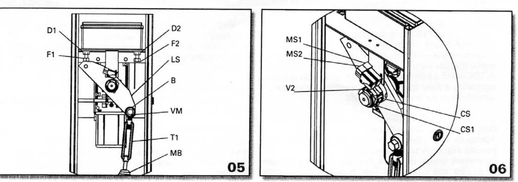
7 GENERAL SAFETY RULES Our compliments for your excellent choice. This Solar Boom gate has been produced according to a high quality and strict reliability, that's why it will assure you long-lasting performance. This manual will offer you all the information you may need to install your barrier and to safe guard your safety. All our products have been made in conformity with the regulations in force. We recommend using original part only, during the installation and the upkeep. However, the caution is unquestionably indispensable and nothing is better than preventing accidents. IMPORTANT Any installation or repair, or adjustment of the working machinery by unqualified people is strictly prohibited unless all the necessary precautions: power supply disconnected (included possible batteries). All moving mechanism must be provided with suitable protections. ECA Electronic Engineering Pty LTD is not responsible for any possible damages or injuries to people, object or animals, caused by any use not provided for this manual and/or any unauthorized modification of the product. Keep this manual enclosing it with technical brochure of installation in a suitable place well-know by all the interested people. You have to operate the elimination of the packing material (cardboard, plastic, polystyrene, etc.) in conformity with the regulations in force, remembering that for a child a plastic envelope could be extremely dangerous. You have to teach the people employed in using the automation about the control and security systems of the installation. Don't install this product in explosive places. UPKEEP For any kind of upkeep, you have always to disconnect the solar panel and batteries. For a correct upkeep of the installation follow these instructions: Clean periodically the photocells. Checking by qualified people the electronic clutch (see the paragraph "installation of the electronic central unit"). In case of malfunction seek information from qualified people. DEMOLITION You have to operate the elimination of the materials in conformity with the regulations in force. All material must be divided by type (copper, aluminum, plastic, electrical central unit). However there are not materials considered dangerous for the handler. DISMANTLING In order to dismantle or to move away the automation, follow these instructions: Disconnect batteries and solar panel and all the electrical accessories. Dismantle the control console and all the other components of the installation. If you have noticed that some components have been damaged, you have to replace them. PRODUCT TYPE The CA45000 Boom Gate has been designed and constructed to open barrier arms up to 5 meters in length. ECA Electronic Engineering Pty LTD does not assume any responsibility for other use than the intended use of the Boom Gate. ATTENTION: The barrier is not equipped with a mechanical clutch and therefore when installed must be connected to a special ECA Electronic Engineering Pty LTD control unit only. USE OF THE MECHANISM Attention, for personnel safety it is of vital importance to carry out the following instructions. Keep these instructions in a safe place. Do not allow children to play with the fixed or remote controls of the gate. Place the remote controls out of the reach of children. As the mechanism can be controlled nearby or at a distance using push buttons or remote controls it is indispensable that the efficiency of all safety devices be checked frequently. We recommend periodical checks (every six months) by qualified personnel to adjust the electronic clutch. To adjust this protection device, see the Paragraph "Electronic clutch adjustment" in the instruction manual of the electronic control unit. PRELIMINARY CHECKS Read carefully all parts of this manual. Check that the product was not damaged during transportation. Check that the electrical plant conforms to the characteristics required by the gear motor. Check that an adequate grounding plant exists and that all metallic parts are connected to this plant. We remind you that the mechanism facilitates use of the barrier and does not resolve problems due to defects, bad installation or lack of maintenance to the barrier. LUBRICATION All ECA barriers are supplied with permanent grease lubrication INSTALLATION Important safety instructions for installation. Warning: A bad installation can cause a great deal of damage or harm. Scrupulously follow all installation instructions. ATTENTION: For any reason whatsoever never disassemble the barrier arm when it is in a horizontal position ATTENTION: For any reason whatsoever never carry out an emergency or manual maneuver if the barrier arm is not assembled ATTENTION: Do not release the motor when it's working. For correct commissioning of the ECA barriers, proceed as follows: Locate the point inside the property where the ECA barrier will be installed (figure 1). Construct a solid concrete base with the dimensions illustrated on figure 1; provide a passage for the sheath "G" of the wiring cables and system controls. Before the concrete sets, position the "Ps" plate (OPTIONAL) well down into the concrete making sure that the plate is correctly oriented and perfectly horizontal on both axis (picture 1). 7
8 If a flat solid base is already available on the ground, the barrier can be fixed directly to the base by screws and fixing plugs without using the "Ps" plate. Unscrew the 2 screws "V1" by the supplied Alien key "CH1'.' and remove the "Cp" protection cover and the front door to gain access to the internal cabinet of the barrier (picture 2). Once the concrete has fully set, position the PUNTO barrier onto the "Ps" plate or onto the fixing plugs and tighten the nuts supplied "D" or the plug screws (picture 3). Barrier must be leveled in up right position and turned according to boom selected direction. IN VERTING THE BARRIER OPENING DIRECTION CA5000 barrier is supplied for opening in an anticlockwise direction picture 4. To invert the opening direction proceed as follows: Remove the boom from the barrier before doing the operation of inverting its way of opening from position "A" of the lever "Ls" the spring "Mb" by removing the screw "Vm" (picture 4). Carry out an emergency or manual maneuver (see paragraph Emergency or manual maneuver) and turn the lever "Ls" clockwise by 90 Reassemble the balancing spring "Mb" in position "B" and lock the "Vm" screw (picture 5). BARRIER ARM ADJUSTMENT AND BALANCING Warning: when boom is down, the spring Mb must be under tension (pic 4 and 5); when boom is up, the spring Mb but be released. Assemble the barrier boom and block it. Make an emergency or manual maneuver (see paragraph Emergency or manual maneuver) checking that the boom, from its horizontal position, goes up slowly. In case the boom doesn't go up, (after the arm has been brought to the up right position to unload the spring) Adjust the spring adjuster "T1" (pic. 4-5) increasing the spring tension. ADJUSTING THE MECHANICAL STOPS Carry out an emergency or manual manoeuvre (see paragraph Emergency or manual maneuver) and bring the arm to a vertical position. Using two 17 mm spanners loosen the locking nut "D1" and screw in or out the adjusting screw "F1" until the desired vertical stop position is obtained and then tighten the nut "D1" (pic. 4-5). Bring the barrier arm to a horizontal position, loosen the nut "D2" and adjust the stop "F2" until the desired horizontal stop position is obtained and then tighten the nut "D2" (pic. 4-5). Once the above operation is terminated, carry out a manual opening and closure maneuver to check that the mechanical stops are in the correct position. Be sure that in closing position, the switch "Ms1" has to be touched by cam "Cs". If not, adjust the cam "CS" unscrewing screw "V2" until the cam touches the micro switch "Ms1" (pic. 6) ELECTRICAL CONNECTIONS Carry out electrical connections as shown in the manual of the electronic control unit and bearing in mind the characteristics required by the general assembly drawing. ADJUSTMENT OF ELECTRICAL LIMIT SWITCHES CA5000 is provided with opening and closing limit switches, which control the start of the slow-down cycle of the bar (with anti-clockwise opening as supplied by the manufacturer, limit switch MS1 CLOSE, MS2 OPEN) while the limit switches are not in use, the bar moves at normal speed, as soon as they are employed the stow-down phase of approach to the mechanical stop commences. Move the bar to the desired position for the start of the closing slow-down phase manually, and adjust the corresponding cam CS until the limit switch is triggered. Move the bar to the desired position for the start of the opening slow-down phase manually, and adjust the corresponding cam CS until the limit switches are triggered (figure 6). Carry out an automatic operation and check the exact position of the cams. TESTING Starting from the barrier closed position, carry out complete OPEN and CLOSE cycles to check for correct positioning of the limit switches and the function of the safety devices installed. Reassemble the front door and the protection guard "Cp'.' Instruct all personnel involved with operating the mechanism about the commands, safety devices, emergency maneuver and danger involved when operating the mechanism. Fill in the technical file for the installation and fulfill any obligations required by regulations in force. Correct functioning of the CA5000 barrier is guaranteed only and exclusively when equipped with ECA safety devices and only when equipped with an original Control Panel. EMERGENCY OR MANUAL MANOEUVRE An emergency or manual maneuver is carried out during the installation stage and only in the case of malfunction of the mechanism or in the absence of electrical power. ATTENTION: Do not release or put in automatic the motor when it's working ATTENTION: Never carry an emergency or manual maneuver if the barrier arm is not assembled. ATTENTION: Never disassemble the barrier arm when it is in a horizontal position. Disconnect power Insert the special "Ch" key in to the "Sb" lock and turn it in an clockwise for 180 until the mechanism unlocks (picture 7). Remove the pawl from the lock and insert the Alien key CH1 in the hole until you reach the proper place (pic.8). Turn the key CH1 anticlockwise until its end and lift the boom up manually. To put the barrier in automatic, turn the key CH1 clockwise until its end. Take the key CH1 off, re-fit the pawl into the lock SB and close the protection lid TA. Keep the "Ch 1" key in a safe place that is known only to the personnel who can operate the mechanism. Reconnect the power making sure that no personnel are in the area where the barrier is moving. ECA ELECTRNIC ENGINEERING Pty. LTD. 465 Hawthorn Rd. Caulfield Sth Vic. Australia. Tel: Fax:
9 9
ARACHNE 230V 24V- 12V
 SWING GATES OPERATOR SERIE ARACHNE 12V-24V-220V INSTRUCTIONS MANUAL SAFETY Our compliments for your excellent choice. Your new electromechanical gear motor has been produced according to a high quality
SARGON S - M - L. All rights reserved INSTALLATION MANUAL
 INSTALLATION MANUAL Our compliments for your excellent choice. SARGON LINE S (300mm) M (400mm) and L (600mm) electro-mechanical gear motor has been produced for reliability and high quality. This Manual
EC DECLARATION OF CONFORMITY FOR MACHINES (DIRECTIVE 98/37/EC) WARNINGS FOR THE INSTALLER
 WARNINGS FOR THE INSTALLER") EC DECLARATION OF CONFORMITY FOR MACHINES (DIRECTIVE 98/37/EC) Manufacturer: Address: Declares that: FAAC S.p.A. Via Benini, 1-40069 Zola Predosa BOLOGNA - ITALY 740-24V mod. operator is built to be integrated
EC DECLARATION OF CONFORMITY FOR MACHINES (DIRECTIVE 98/37/EC) Manufacturer: Address: Declares that: FAAC S.p.A. Via Benini, 1-40069 Zola Predosa BOLOGNA - ITALY 740-24V mod. operator is built to be integrated
DKC400Y AC Sliding Gate Installation Manual. Sliding Gate Opener. Model: DKC400Y. Installation Manual WARNING
 Sliding Gate Opener Model: DKC400Y Installation Manual WARNING Read and thoroughly understand all instructions before installing or operating this automatic gate opener. Failure to do so may cause serious
Index. 4. DESCRIPTION... p PRELIMINARY CHECKS... p ASSEMBLY... p. 6
 D1000 Index GENERAL SAFETY INSTRUCTIONS FOR INSTALLATION AND MAINTENANCE... p. 2 TOOLS AND MATERIALS... p. 2 DECLARATION OF CONFORMITY... p. 3 WARNINGS FOR THE INSTALLER... p. 3 1. DIMENSIONS... p. 4 2.
AgriWheel Single Gate Kit Low Voltage & Solar. Installation & Operating Instructions
 AgriWheel Single Gate Kit Low Voltage & Solar Installation & Operating Instructions Thank you for purchasing you AgriWheel system. Please remove the lids from both the machine and control box and remove
L I M I T E D L I F E T I M E W A R R A N T Y
 L I M I T E D L I F E T I M E W A R R A N T Y Products manufactured and sold by OMEGA RESEARCH & DEVELOPMENT, INC. (the Company), are warranted to be free from defects in materials and workmanship under
Index. 4 DESCRIPTION... p. 5 5 PRELIMINARY CHECKS... p. 5 6 ASSEMBLY... p. 6
 Index GENERAL SAFETY INSTRUCTIONS FOR INSTALLATION AND MAINTENANCE... p. 2 TOOLS AND MATERIALS... p. 2 DECLARATION OF CONFORMITY... p. 3 WARNINGS FOR THE INSTALLER... p. 3 1 DIMENSIONS... p. 4 2 TECHNICAL
Index. 4. DESCRIPTION... p PRELIMINARY CHECKS... p ASSEMBLY... p. 6
 Index GENERAL SAFETY INSTRUCTIONS FOR INSTALLATION AND MAINTENANCE... p. 2 TOOLS AND MATERIALS... p. 2 DECLARATION OF CONFORMITY... p. 3 WARNINGS FOR THE INSTALLER... p. 3 1. DIMENSIONS... p. 4 2. TECHNICAL
Model PRO-9775T Owner's Manual 4 Button Remote Start Security System With Plug-In Shock Sensor & Starter Disable
 Model PRO-9775T Owner's Manual 4 Button Remote Start Security System With Plug-In Shock Sensor & Starter Disable FEATURES:! 2 Four Button Programmable RF Transmitters! Four Channel Code Learning Receiver
Model PRO-9675FT4 Owner's Manual
 Model PRO-9675FT4 Owner's Manual 4 Button Remote Start Security System With Plug-In Shock Sensor & Starter Disable FEATURES : w 2 Four Button Programmable RF Transmitters w Four Channel Code Learning Receiver
FROG KIT. Installation Instructions for a Pair of gates... TECHNICAL HELPLINE THE FROG-P KIT CONSISTS OF:
 CAME UNITED KINGDOM LTD UNIT 3 ORCHARD PARK INDUSTRIAL ESTATE, TOWN STREET, SANDIACRE, NOTTINGHAM NG10 5BP TEL: 0115 921 0430 FAX: 0115 921 0431 TECHNICAL HELPLINE 0115 921 0430 INTERNET - www.cameuk.com
CONTROL UNIT BIOS2. Manual for installation. Programmable Control board for wings gates.
 Programmable Control board for wings gates www.remotecontrolgates.co.uk Manual for installation Compatible from firmware version BIOS2BT02 CONTROL UNIT BIOS2 1. Introduzione The control unit BIOS2 is particularly
Installation and Set Up Instructions
 SL 2000 DC2 SLIDING GATE MOTOR KIT Solar Powered and 12V Low Voltage Installation and Set Up Instructions Unit 27 / 49 Corporate Boulevard Bayswater Vic 3153 Phone 1800 111 930 Email info@gforceautogates.com.au
EC DECLARATION OF CONFORMITY FOR MACHINES WARNINGS FOR THE INSTALLER
 EC DECLARATION OF CONFORMITY FOR MACHINES (DIRECTIVE 2006/42/EC) Manufacturer: Address: Declares that: FAAC S.p.A. Via Benini, 1-40069 Zola Predosa BOLOGNA - ITALY 740 / 741 mod. operator is built to be
Instruction Manual for the. E-SL 450 Series
 Instruction Manual for the E-SL 450 Series Estate Slide Summary of Functions The Estate Slide is only to be used for vehicular Slide gates in a Class I setting. Class I: A vehicular gate opener (or system)
AUTOMATIC CONTROL ROLLING DOOR OPENER
 AUTOMATIC CONTROL ROLLING DOOR OPENER INSTALLATION INSTRUCTION AUTOMATIC OBSTRUCT PHOTOELECTRIC BEAM ROLLING CODE SYSTEM AUTO CLOSE DOOR ANTI-THEFT SYSTEM INSTALLATION INSTRUCTION AND RDO OWNERS MANUAL
Installation and Set Up Instructions
 Model FG 5-7 / SW 5-7 / DSW 5-7 Swing Gate Motor Kit Solar powered and 12V Low Voltage Installation and Set Up Instructions Unit 27 / 49 Corporate Boulevard Bayswater Vic 3153 Phone 1800 111 930 Email
Installation and Set Up Instructions
 SL SLIDING GATE MOTOR KIT Solar Powered and 12V Low Voltage Installation and Set Up Instructions Unit 27 / 49 Corporate Boulevard Bayswater Vic 3153 Phone 1800 111 930 Email info@gforceautogates.com.au
Roller Door Operator
 INSTALLATION INSTRUCTIONS AND OWNERS MANUAL Roller Door Operator IMPORTANT PLEASE READ THESE INSTRUCTIONS CAREFULLY PRIOR TO COMMENCING THE INSTALLATION OF THE OPERATOR UNIT CAUTION This Automatic Opener
Letron Auto Gates (Australia) Pty. Ltd. User s Installation Manual
 Pty. Ltd. User s Installation Manual") Letron Auto Gates (Australia) Pty. Ltd. User s Installation Manual Sliding Gate Motor AUTOMATIC OBSTRUCT PHOTO ELECTRIC BEAM ROLLING CODE SYSTEM AUTO CLOSE DOOR SOLAR COMPATIBLE ( DC ONLY ) Model SL810
Letron Auto Gates (Australia) Pty. Ltd. User s Installation Manual Sliding Gate Motor AUTOMATIC OBSTRUCT PHOTO ELECTRIC BEAM ROLLING CODE SYSTEM AUTO CLOSE DOOR SOLAR COMPATIBLE ( DC ONLY ) Model SL810
EC MACHINE DIRECTIVE COMPLIANCE DECLARATION
 EC MACHINE DIRECTIVE COMPLIANCE DECLARATION (DIRECTIVE 89/392 EEC, APPENDIX II, PART B) Manufacturer: FAAC S.p.A. Address: Via Benini, 1 40069 - Zola Predosa BOLOGNA - ITALY Hereby declares that: the 770
Installation and Maintenancee Manual
 Installation and Maintenancee Manual Commercial Boom Gate Operator Model: GDS BOOM 4 and 6 A.B.N. 62 059 806 405 Nov 2013 Section No: CONTENTS Page Number: 1 Safety Precautions 3 2 Specifications 4 3 Mechanical
HIGH SPEED SLIDING GATE OPENER
 HIGH SPEED SLIDING GATE OPENER Model: is1200 + Elsema s Eclipse Control Card with GDS Operator USER MANUAL CONTENTS Section No: Page No: 1 Safety Precautions 3 2 Wiring Requirements 4 3 Installation details
D Vers. 03 ELECTROMECHANICAL AUTOMATION FOR SWING GATES
 E5 D811007 15-09-99 Vers. 03 ELECTROMECHANICAL AUTOMATION FOR SWING GATES 122 This product complies with recognised technical standards and safety regulations. We declare that this product is in conformity
Porte 150 Users Manual Swing Gate Opener 24V DC
 Porte 150 Users Manual Swing Gate Opener 24V DC for residential use only Signal Light Push-button Control Box 14 Contents 1. Important Safety Information 2. Product Description and Application 2.1 Application
Table of Contents. General Safety Preparation for Installation Parts List Optional Accessories Part List... 5
 REV 12a Table of Contents General Safety....... 2 Preparation for Installation....... 3 Parts List....... 4 Optional Accessories Part List...... 5 Technical Specifications & Feature...... 5 Installation
Sectional and Tilting Door Opener
 Sectional and Tilting Door Opener Installation Instructions and User Guide 600 800 1000 S/N WARNING Please read the manual carefully before installation and use. The installation of your new door opener
User Guide 1 WAY FM MANUAL TRANSMISSION REMOTE STARTER. Table of Contents. Introduction
 1 WAY FM MANUAL TRANSMISSION REMOTE STARTER User Guide Table of Contents... 1 Introduction... 1 Using the Remote Control... 2 Multi-Level Features (default state)... 2 Remote-Starting Your Vehicle... 3
SWING GATE OPENERS 24V DC GEAR MOTOR
 SWING GATE OPENERS 24V DC GEAR MOTOR FOR RESIDENTIAL USER MANUAL Flashing Light Push Button Control box Gate 2 Gate 1 Index 1. Warnings 2 4. Technical Characteristics 16 2. Product Description 2.1 Applications
OMATION FOR SLIDING GATES LINESTAR INSTALLATION MANUAL
 AUTOMA OMATION FOR SLIDING GATES LINESTAR INSTALLATION MANUAL CONTENTS 1.0 Description of the system parts page 3 1.1 Description of the parties of the group gearmotor page 3 2.0 General characteristics
FORCE SPD 800/1500/2000
 English AUTOMATION SYSTEMS FOR SLIDING GATES Operating and installation instructions FORCE SPD 800/1500/2000 v1.0 Rev 11/2012 INDEX 1) General Safety Regulations... pág. 01 2) Description... pág. 02 3)
ROSSO EVO User s and Installer s manual
 ROSSO EVO User s and Installer s manual v1.0 REV. 01/2014 00. CONTENT 01. SAFETY INSTRUCTIONS INDEX STANDARDS TO FOLLOW 00. CONTENT index pag 01.A 01. SAFETY INSTRUCTIONS standards to follow pag 01.B 02.
INSTALLATION INSTRUCTIONS AND OPERATION MANUAL
 INSTALLATION INSTRUCTIONS AND OPERATION MANUAL UL325-2010 Compliant Commercial and Industrial Door Operator Logic Control Continuous Duty IMPORTANT INSTALLATION INSTRUCTIONS WARNING To reduce the risk
MBM8 / MBM11- Barriers. Installer and User s manual
 MBM8 / MBM11- Barriers Installer and User s manual v2.0 REV. 01/2014 00. CONTENT 01.SAFETY INSTRUCTIONS INDEX 00. CONTENT index page 01.A 01. SAFETY INSTRUCTIONS standards to follow page 01.B 02. PACKAGE
Contents. EC DECLARATION OF CONFORMITY FOR MACHINES... p. 10. WARNINGS FOR THE INSTALLER... p. 10
 Contents EC DECLARATION OF CONFORMITY FOR MACHINES... p. 10 WARNINGS FOR THE INSTALLER... p. 10 1. DESCRIPTION AND TECHNICAL SPECIFICATIONS... p. 11 1.1. DIMENSIONS... p. 11 2. ELECTRIC DEVICES (standard
DESIGNED FOR RESIDENTIAL APPLICATION KIT PL600/PL1000 SLIDING GATE OPENERS
 SLIDING GATE OPENER DESIGNED FOR RESIDENTIAL APPLICATION KIT PL600/PL1000 SLIDING GATE OPENERS The strongest solution for sliding gates PL600/PL1000 electro-mechanical sliding gate openers are designed
MEGA WAY LCD PAGER ALARM WITH REMOTE ENGINE STARTER. Operation Manual MEGATRONIX CHATSWORTH, CA U.S.A. MEGA 2700 OPERATE 1
 MEGA 2700 2-WAY LCD PAGER ALARM WITH REMOTE ENGINE STARTER Operation Manual MEGATRONIX CHATSWORTH, CA U.S.A. MEGA 2700 OPERATE 1 2 WARNINGS: As with any product that performs automatic functions, there
USER MANUAL. Automated Vehicular Boom Gate. Version: 1.0 Date: March, 2015
 USER MANUAL Automated Vehicular Boom Gate Version: 1.0 Date: March, 2015 Automatic Gates are not for Pedestrians! Automatic gate openers are designed for vehicular traffic. They are powerful, accordingly,
SWING GATE OPENERS 24V DC GEAR MOTOR
 SWING GATE OPENERS 24V DC GEAR MOTOR FOR RESIDENTIAL USER MANUAL Flashing Light Push Button Control box Gate 2 Gate 1 Index Warnings 2 5. Technical Characteristics 21 1. Product Description and Applications
Sliding Gate Operator User's Manual
 Sliding Gate Operator User's Manual PY800AC/PY00AC. Products introduction Please read the instructions carefully before proceeding. MCU is supplied to control the gate operator. Keypad / single button
DTS SECURITY P.O.BOX 3399 EDENVALE 1610 Base plate-mounting instructions TELEPHONE
 DTS ECO 500 SLIDING GATE MOTOR INSTALLATION MANUAL DTS SECURITY P.O.BOX 3399 EDENVALE 1610 Base plate-mounting instructions TELEPHONE 086 1000 387 Spartan +2711 392 5540 (H/O) Pretoria +2712 361 5528 Alberton
UNDERGROUND OPERATOR FOR SWINGING GATES. WARNING!! Before installing, thoroughly read this manual that is an integral part of the pack
 UNDERGROUND OPERATOR FOR SWINGING GATES COMPAS 2 WARNING!! Before installing, thoroughly read this manual that is an integral part of the pack Our products if installed by qualified personnel capable to
Installation manual ASTER AUTOMATION FOR SWING GATES 11_16
 Installation manual ASTER AUTOMATION FOR SWING GATES 11_16 Contents 1. GENERAL SAFETY PRECAUTIONS... page 01 2. INTENDED USE AND APPLICATION... page 01 2.1 Kit contents... page 01 2.2 Technical features...
SECTIONAL AND TILTING DOOR OPENER INSTALLATION INSTRUCTIONS AND USER GUIDE. Comfort 800E/1000E
 SECTIONAL AND TILTING DOOR OPENER INSTALLATION INSTRUCTIONS AND USER GUIDE Comfort 800E/1000E WARNING Please read the manual carefully before installation and use. The installation of your new door opener
Instruction Manual MB4 Rolling garage door opener
 Instruction Manual MB4 Rolling garage door opener INSTALLATION INSTRUCTIONS OWNERS COPY 1 WARNING: It is vital for the safety of persons to follow all instructions. Failure to comply with the installation
L /2013 rev 0 BISON 35 OTI UNIONE NAZIONALE COSTRUTTORI AUTOMATISMI PER CANCELLI, PORTE SERRANDE ED AFFINI
 L8543019 04/2013 rev 0 BISON 35 OTI UNIONE NAZIONALE COSTRUTTORI AUTOMATISMI PER CANCELLI, PORTE SERRANDE ED AFFINI 1 458 250 A F 645 477 B 195 470 270 2 C 13 ±5 156 70 2 3 4 D2 R D2 I D1 T 5 W D H G R
TMT Boxer 24v slider motor installation notes from EasyGate
 TMT Boxer 24v slider motor installation notes from EasyGate Install Physical Gate Stops Physical Gate Stops MUST be installed at each end of your gate. If the Limit Switch on the boxer motor fails to stop
INSTRUCTIONS FOR INSTALLATION
 HYDRAULIC OPERATOR MODO 110-110/L FOR SINGLE- OR DOUBLE-WING SWING GATES INSTRUCTIONS FOR INSTALLATION GENERAL WARNINGS These warnings constitute an integral and essential part of the product and must
INSPECTIONS AND MAINTENANCE
 GB INSTRUCTIONS MANUAL STRABUC 930 ARMOURED OIL-HYDRAULIC RISING BOLLARD COMPONENTS strabuc 930 RELEASE KEY PROTECTION PLUG TO ACCESS RELEASE HOLE BOLLARD COVER 12V WARNING LIGHTS REFLECTORS RISING POST
F ERNI K I T THE FERNI-S KIT CONSISTS OF:
 CAME UNITED KINGDOM LTD ORCHARD PARK INDUSTRIAL ESTATE TOWN STREET, SANDIACRE, NOTTINGHAM, NG10 5BP TEL: 0115 921 0430 FAX: 0115 921 0431 INTERNET - www.cameuk.com E-MAIL - enquiries@cameuk.com TECHNICAL
Sectional and Tilting Door Opener Installation Instructions and User Guide
 Sectional and Tilting Door Opener Installation Instructions and User Guide ET-600E ET-800E ET-1000E S/N WARNING Please read the manual carefully before installation and use. The installation of your new
Sliding Gate Operator User's Manual
 Sliding Gate Operator User's Manual SL600AC. Products introduction Please read the instructions carefully before proceeding. MCU is supplied to control the gate operator. Keypad / single button interface.
INSTALLATION INSTRUCTIONS AND OPERATION MANUAL
 INSTALLATION INSTRUCTIONS AND OPERATION MANUAL NEMA 4X UL325-2010 Compliant Commercial and Industrial Door Operator Logic Control Continuous Duty IMPORTANT INSTALLATION INSTRUCTIONS WARNING To reduce the
Barrier Gate Manual. (DZX2.1 Control Board) (The third version) (Pictures for reference only, the product prevail in kind)
 (The third version) (Pictures for reference only, the product prevail in kind)") Barrier Gate Manual (DZX2. Control Board) (The third version) (Pictures for reference only, the product prevail in kind) Contents. Brief Introduction... 2. Functions and Features... 3. Technical Data...2
Barrier Gate Manual (DZX2. Control Board) (The third version) (Pictures for reference only, the product prevail in kind) Contents. Brief Introduction... 2. Functions and Features... 3. Technical Data...2
Installation Manual DELT. Platform stairlift. Web: Tel: Mobile:
 Installation Manual DELT Platform stairlift Web: www.lehner-lifttechnik.at Tel: +4372783514 Email: office@lehnerlifttechnik.at Mobile: +436641612980 Table of content OBSERVE THE FOLLOWING POINTS BEFORE
TWO-WAY LED AUTOMATIC TRANSMISSION REMOTE STARTER. User Guide WARNING
 TWO-WAY LED AUTOMATIC TRANSMISSION REMOTE STARTER User Guide WARNING It is the responsibility of the vehicle operator to ensure their vehicle is parked in a safe and responsible manner. 1. When leaving
BARRY BARRIER GATE AUTOMATION
 BARRY BARRIER GATE AUTOMATION Installation Manual 1. WARNINGS AND GENERAL SAFETY INSTUCTIONS This manual contains important safety information. An incorrect installation or an improper use may cause serious
DTS 412/512/624 SLIDING GATE MOTOR INSTALLATION MANUAL
 DTS 412/512/624 SLIDING GATE MOTOR INSTALLATION MANUAL DTS SECURITY P.O.BOX 3399 EDENVALE 1610 TELEPHONE 086 1000 387 Base plate-mounting instructions Alberton 011 907 8846 Centurion 012 653 4434 Edenvale
INSTALLATION INSTRUCTIONS AND OPERATION MANUAL
 INSTALLATION INSTRUCTIONS AND OPERATION MANUAL Commercial and Industrial Fire Door Operator Logic Control Restricted Duty Fire Door Operators IMPORTANT INSTALLATION INSTRUCTIONS WARNING To reduce the risk
L /2012 rev 0 BISON 30 OTI UNIONE NAZIONALE COSTRUTTORI AUTOMATISMI PER CANCELLI, PORTE SERRANDE ED AFFINI
 L8542968 07/2012 rev 0 BISON 30 OTI UNIONE NAZIONALE COSTRUTTORI AUTOMATISMI PER CANCELLI, PORTE SERRANDE ED AFFINI 1 458 250 A F 645 477 B 195 470 270 2 C 13 ±5 156 70 2 3 4 D2 R D2 I D1 T 5 W D H G R
Jet 500/ 800 Users Manual Sliding Gate Opener
 Jet 500/ 800 Users Manual Sliding Gate er for residential use only 18 Contents 1. Important Safety Information 2. Installation 2.1 Standard Installation Demonstration 2.2 Components description 2.3 Operator
Sectional And Tilting Door Opener
 Sectional And Tilting Door Opener Installation Instructions and User Guide FS 600 FS 1000 FS 1200 600N 1000N 1200N FS 600-Speed FS 1000-Speed 600N 1000N S/N WARNING Please read the manual carefully before
BAYT 980. Oil-hydraulic OIL-HYDRAULIC BARRIER FOR TRAFFIC CONTROL INSTALLATION MANUAL. code 4425 Post with fixing base. POLO 44 - optional -
 Oleodinamica BAYT 980 Oil-hydraulic OIL-HYDRAULIC BARRIER FOR TRAFFIC CONTROL POLO 44 - optional - BAYT 980 560 code 4425 Post with fixing base the gate opener Made in Italy INSTALLATION MANUAL GB INSTRUCTIONS
Instruction Manual LA-SDO1 Sectional garage door opener
 Instruction Manual LA-SDO1 Sectional garage door opener INSTALLATION INSTRUCTIONS OWNERS COPY 1 WARNING: It is vital for the safety of persons to follow all instructions. Failure to comply with the installation
INSTRUCTION INVERTER COMPACT FOR SLIDING GATES /R0 10/11/2017
 INSTRUCTI INVERTER COMPACT FOR SLIDING GATES 6-1622616 /R0 10/11/2017 2 / 20 3 / 20 1. INTRO The control unit INVERTER COMPACT is integrated in the motor KALOS XL. It is a device suitable for operating
L /2010 rev 5 MATRIX MATRIX-RE CP.BULL CP.BULL-RI UNIONE NAZIONALE COSTRUTTORI AUTOMATISMI PER CANCELLI, PORTE SERRANDE ED AFFINI
 L8542124 07/2010 rev 5 MATRIX MATRIX-RE CP.BULL CP.BULL-RI UNIONE NAZIONALE COSTRUTTORI AUTOMATISMI PER CANCELLI, PORTE SERRANDE ED AFFINI MATRIX / MATRIX-RE / CP.BULL / CP.BULL-RI MATRIX > BULL10M SC/15M
IRREVERSIBLE OPERATOR FOR SWING GATES AND DOORS
 VH IRREVERSIBLE OPERATOR FOR SWING GATES AND DOORS WARNING!! Before installing, thoroughly read this manual that is an integral part of the pack Our products if installed by qualified personnel capable
TECHNICAL DATA HYDRAULIC UNIT
 GB INSTRUCTIONS MANUAL RISING BOLLARD OIL-HYDRAULIC AUTOMATION COMPONENTS strabuc 918 RELEASE KEY PLUG FOR RELEASE HOLE BOLLARD COVER 12 V WARNING LIGHTS REFLECTORS COMPLETELY RETRACTABLE POST WITH ELECTROPHORESIS
Ditec E1A. IP2045EN Technical manual. Control panel installation manual for one motor automation with built-in radio.
 Ditec EA Control panel installation manual for one motor automation with built-in radio. EA RF FUSE CT 2 3 4 5 C O M SIG J2 PRG NIO F2 JR4 JR0 SO 6>4 IN JR3 R TC TM AUX A N T PT3 JR6 F FUSE 2 0 2 POWER
Roll Up Door Operator
 INSTRUCTIONS & OWNERS MANUAL Roll Up Door Operator 2 INDEX Preparation before installation 4. Terms and definitions 5. Pictures & names of parts 6. Mounting the weight bar 7. Installing the operator 7.
R3 Roller Garage Door Opener
 R3 Roller Garage Door Opener INSTALLATION INSTRUCTIONS OWNERS COPY 1 WARNING: It is vital for the safety of persons to follow all instructions. Failure to comply with the installation instructions and
SLIDE NEW CONTROL BOARD
 GB SLIDE NEW CONTROL BOARD CN1 CN2 3 4 5 FUSE 2 RL2 RL1 FUSE 1 TR2 TR1 TR3 TR4 U 1 JP1 Ld2 CMR 3 4 CN E Ld7 Ld6 Ld5Ld4Ld3 CN3 3 4 5 6 7 8 9 10 11 SW 12 13 14 Ld1 P2 P1 FUSE 1 FUSE 2 TR1 TR2 TR3 TR4 SW.1
Marzocchi Suspension D-Street 24" D-Street 24" Technical instructions
 Technical instructions Exploded view - D-Street 24" 80 Rif. Code Quantity D-Street 24" 80 - Oil levels Position Oil type Quantity (cc) Right fork leg SAE 7,5-550013 185 Left fork leg SAE 7,5-550013 185
Installation Manual. Swing Gate System. Leading the way...
 Installation Manual 402 Swing Gate System Leading the way... Contents EC DECLARATION OF CONFORMITY FOR MACHINES... p. 2 WARNINGS FOR THE INSTALLER... p. 2 1. DESCRIPTION AND TECHNICAL SPECIFICATIONS...
L /2012 rev 0 BISON 45 OTI UNIONE NAZIONALE COSTRUTTORI AUTOMATISMI PER CANCELLI, PORTE SERRANDE ED AFFINI
 L8542965 03/2012 rev 0 BISON 45 OTI UNIONE NAZIONALE COSTRUTTORI AUTOMATISMI PER CANCELLI, PORTE SERRANDE ED AFFINI 1 470 327 F A 500 825 B 243.5 2 C 445 210 15 ±5 205 92 50 2 3 4 I D2 D2 D1 5 T 6 D A
RS-230-DP. Operation Guide
 RS-230-DP Deluxe Keyless Entry & Remote Start July 27, 2010 Operation Guide Temporary cover. Color cover is in a separate file. Table Of Contents Introduction...2 The Transmitter...3 Transmitter Functions...3
EDR G /03
 1 Important safety instructions for operation It is vital for the safety of persons to follow all instructions. Save these instructions. WARNING Do not allow children to play with door controls. Keep remote
INSTALLATION GUIDE Table of Contents
 CT-3100 Automatic transmission remote engine starter systems. What s included..2 INSTALLATION GUIDE Table of Contents Door lock toggle mode..... 4 Notice...2 Installation points to remember. 2 Features..2
EC DECLARATION OF CONFORMITY
 EC DECLARATION OF CONFORMITY Manufacturer : Address: Declares that: FAAC S.p.A. Via Benini, 1-40069 Zola Predosa BOLOGNA - ITALY 844 T control board, conforms to the essential safety requirements of the
CA611 Owners Manual CAUTION!
 CA611 Owners Manual CAUTION! Be certain that the vehicle is outdoors before using this or any remote vehicle starting device. A running engine produces dangerous carbon monoxide fumes which can be harmful
IMPORTANT! Remote Control Instructions
 Remote Control Instructions FOR New Tarp Remote Control Installation Use these in place of the rocker switch and solenoid section of instructions in your roll tarp owner s manual. FOR Existing Electric
Automation Swing Gate Opener
 Automation Swing Gate Opener Operating and installation instructions SP EIFFEL 400 V1.0 Rev 08/01 CONTENTS 0) GENERAL SAFETY REGULATIONS...Page 0 1) DESCRIPTION...Page 03 ) TECHNICAL SPECIFICATIONS 3)
AS-1414/ AS User Guide
 AUTOMATIC TRANSMISSION MULTI-CHANNEL REMOTE STARTER SYSTEM AS-1414/ AS-1424 User Guide Introduction...2 Basic Remote Operation...2 Remote-starting Your Vehicle...2 Vehicle Presets...2 Driving Off...3 Idle
XPS-ProFeed Shuttle SERVICE MANUAL. Revised:
 XPS-ProFeed Shuttle SERVICE MANUAL Revised: 1-14-15 RENA SYSTEMS INC. 910 East Main Street; Suite 200 Norristown, PA 19401-4110 Phone: (610) 650-9170 Fax: (610) 270-3947 Web Site: www.renausa.com SAFETY
LIFTMASTER MAGIC BUTTON FS10 & LPK5 FAST SLIDER
 R MAGIC BUTTON FS0 & LPK5 FAST SLIDER OPERATORS MANUAL FEATURES High speed -800mm/second Corrosion resistant - Hot dip galvanised base with stainless steel cover Speed flexibility - Slow start / slow stop
INSTALLATION GUIDE. FCC ID NOTICE
 REV.5 RS. ADVANCED REMOTE STARTER INSTALLATION GUIDE www.security.soundstream.com FCC ID NOTICE This device complies with Part 5 of the FCC rules. Operation is subject to the following conditions:. This
PW320/PW330 USER MANUAL SWING GATE OPENERS 24V DC GEAR MOTOR FOR RESIDENTIAL. Flashing Light. Push Button. Control box. Gate 2.
 PW320/PW330 USER MANUAL SWING GATE OPENERS 24V DC GEAR MOTOR FOR RESIDENTIAL Flashing Light Push Button Control box Gate 2 Gate 1 Declaration of Conformity Applicant: Powertech Electronics Inc. Manufacturer:
INSTALLATION M ANUAL
 INSTALLATION MANUAL Table of Contents UL Listings Installing the Warning Sign / Precautions Methods of Installation / Compact Installation Mounting the Secondary Entrapment / Welding Gate Arn Mounting
FEATURES AND OPERATIONS
 REMOTE STARTER - ANTI-START SYSTEM SECURITY SYSTEM For An Automatic Or Manual Transmission Vehicles Table Of Contents Welcome Important Information Remote starter with Automatic Transmission Keyless running
PW150/PW200 USER MANUAL SWING GATE OPENERS 24V DC GEAR MOTOR
 PW150/PW200 USER MANUAL SWING GATE OPENERS 24V DC GEAR MOTOR FOR RESIDENTIAL Flashing Light Push Button Control box Declaration of Conformity Applicant: Powertech Electronics Inc. Manufacturer: Timotion
EC MACHINE DIRECTIVE COMPLIANCE DECLARATION
 770 EC MACHINE DIRECTIVE COMPLIANCE DECLARATION (DIRECTIVE 89/392 EEC, APPENDIX II, PART B) Manufacturer: FAAC S.p.A. Address: Via Benini, 1 40069 - Zola Predosa BOLOGNA - ITALY Hereby declares that: the
REMOTE CENTRAL LOCK. Model: CLRxxx-ULT
 REMOTE CENTRAL LOCK Model: CLRxxx-ULT Contents Remote Lock, Remote Unlock, Car Finder, Remote Boot release:, Power Window outoput, Learning Transmitter Codes... page 3 Wiring Diagram... page 4 Introduction,
DUCATI Control box. DUCATI Kontrol large DUCATI Kontrol small 10. PREDISPOSITIONS
 DUCATI Control box 10. PREDISPOSITIONS Prepare the insulated cable ducts for motors and accessories wires (not supplied). Prepare the power plant to the location where you intend to attach the control
GLM SERIES CONTROL Users Manual Rev:
 GLM SERIES CONTROL Users Manual Rev: 808062 Connecting Power Page 2 Motor Terminal Wiring Diagrams Page 3 Getting Started / Setup Page 4 1. Obstruction Detection Devices Page 4 2. Checking Power and Direction
TWO-WAY LED MANUAL / AUTOMATIC TRANSMISSION REMOTE STARTER. User Guide WARNING
 TWO-WAY LED MANUAL / AUTOMATIC TRANSMISSION REMOTE STARTER User Guide WARNING It is the responsibility of the vehicle operator to ensure their vehicle is parked in a safe and responsible manner. 1. a)
VERG 24V BARRIER. English
 VERG 24V BARRIER General features VERG 24V is an electro-mechanical barrier (2, 3, 4, 5 m) recommended for the automation of access points which require a high opening/closing speed (parking lots, motorways,
APOLLO Gate Operators, Inc.
 APOLLO Gate Operators, Inc. Model BA12 12 VOLT DC BARRIER ARM OPERATOR INSTALLATION MANUAL 0707 CONTENTS IMPORTANT SAFETY INSTRUCTIONS... 3 Applications... 4 Pre-Installation Checklist... 5 Operator Installation...
INSTALLATION INSTRUCTIONS SLIDING SHUTTER MOTOR
 INSTALLATION INSTRUCTIONS SLIDING SHUTTER MOTOR VERSION 1-04 2, rue des Métiers 21110 Genlis FRANCE Tél. : +33 3 80 37 85 71 Fax : +33 3 80 37 88 61 http://www.wimove.fr GUARANTEE CERTIFICATE CAUTION NOTICE
AS-1535 SH User Guide
 A U T O M A T I C T R A N S M I S S I O N M U L T I C H A N N E L R E M O T E S T A R T E R S Y S T E M AS-1535 SH User Guide Transmitter Part Number and Module Serial Number... 2 Introduction... 2 Basic