The Fischertechnik ACEs (Robo Starter Model kit)
|
|
|
- Dylan Fowler
- 6 years ago
- Views:
Transcription


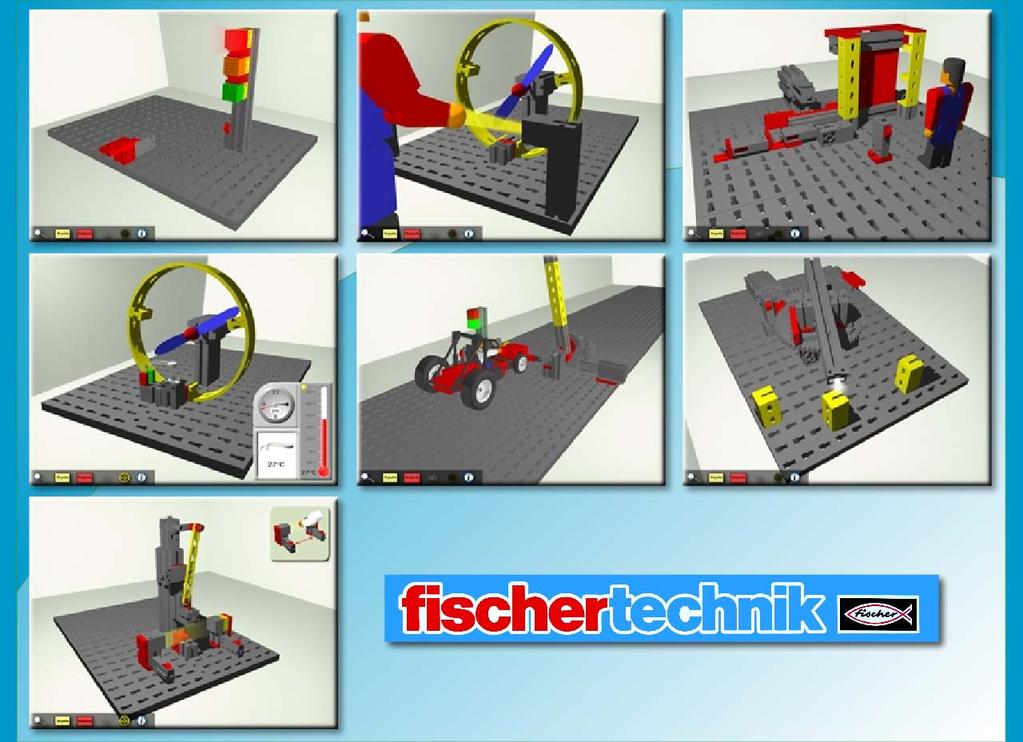
1 The Fischertechnik ACEs (Robo Starter Model kit)

 will alter to stop the traffic if a pedestrian presses the push switch.")
2 (01) Traffic Light The set of traffic lights is used to stop traffic so a pedestrian can safely cross the road. It has a master switch which can be used to deactivate the normal light sequence during repair work. Inputs: 1) Pedestrian (I1) 2) Master (I2) 1) Red Light (M1) 2) Amber Light (M2) 3) Green Light (M3) Create a program to operate the traffic lights in the correct sequence. Adapt the program so the lights (usually green) will alter to stop the traffic if a pedestrian presses the push switch. Create a flashing amber light sequence that will operate if the master switch is on. Create a program that operates the pedestrian traffic light sequence unless the master switch is on, when the flashing amber light sequence should take over. Use Reset ACE to set the ACE back to its original start conditions. The pedestrian input (In 1) is a push button switch that is only momentarily On. The master switch (In 2) is operated by a block sliding over a push switch. Click to switch it On, and then again to switch Off. The ACE and the Fischertechnik Traffic Light model: 1. To establish a connection to the interface click on the Connect interface icon. 2. This ACE can synchronise with the real model (the ACE of the model together with the model connected to a control interface). 3. When connecting the model to the control interface check the numbering of the outputs and inputs matches those on the ACE. 4. When the interface is connected, the control of the inputs is taken over by the model, so to activate a switch press the switch on the model not the ACE. 2
 Light Switch (I1) 1) Light Beam (M2) Motor: A) Fan (M1) Program the hand dryer so the blower will operate for a set amount of time when a person places their hand in front of the dryer.")

3 (02) Hand Dryer A person will arrive at the dryer to dry their hands. The dryer has a light barrier, which can be used to detect when a hand is placed in the dryer. Inputs: 1) Light Switch (I1) 1) Light Beam (M2) Motor: A) Fan (M1) Program the hand dryer so the blower will operate for a set amount of time when a person places their hand in front of the dryer. Program the hand dryer so the blower only operates when a hand is front of the dryer (so it switches off immediately when the hand is removed). Use Reset ACE to set the ACE back to its original start conditions. When the light beam (Out 1) is On it will direct its light to the light sensitive switch (In 1) to form a light barrier, and the switch will be On. When a person places their hand in the light barrier they will interrupt the light beam and the light switch will be Off. The fan is operated by using Motor A. The motor operates at one speed in one direction (clockwise) whether the motor is turned forward (Fwd) or reverse (Rev). To operate the fan on the ACE, locate the motor s hot spot, click once for the motor to turn the propeller and then again to switch it off. The ACE and the Fischertechnik Hand Dryer model: 1. If you are writing a control program that can be used with both the ACE and model check the numbering of the outputs and inputs on the model matches those on the ACE. 2. This ACE is not suitable for working alongside the real model. Click on Disconnect ACE to close the ACE before you click on the Connect interface icon to establish a connection to the interface. 3. To activate the light switch on the model use your hand to interrupt the light beam. Tip: If the light switch on the model doesn t respond try bringing the switch and lamp closer together until it does. 3


4 03) Sliding Door A person will arrive at the door and wait for it to open. The model has a push switch that will be used to request that the door opens. The door has a light barrier, which can be used to prevent the door closing as they are passing through it. Inputs: 1) Door Closed (I1) 2) Door Open (I2) 3) Open Door (I3) 4) Light Switch (I4) 1) Light Beam (M2) Motor: A) Door (M1) Create a program that opens the door when someone arrives and presses the open switch. Let them pass through then close it. Create a program that opens the door when someone arrives and presses the open switch. Add safety features: The door should only close if no one is in front of the door (when the light beam is not interrupted). If the beam is interrupted while the door is closing, it should re-open. Use Reset ACE to set the ACE back to its original start conditions (door closed). When the light beam (Out 1) is On it will direct its light to the light sensitive switch (In 4) to form a light barrier, and the switch will be On. When a person stands in front of the door, they will interrupt the light beam and the light switch will be Off. The door is operated by using Motor A. The motor will close the door when turned forward (Fwd) and open it in reverse (Rev). To make the door move on the ACE, locate the motor s hot spot, click once to move it in one direction and then again to move in the other direction. When the door slides up against a door push switch, it will push the switch On. I.e. As the door opens it switches Door Closed (In 1) and then Door Open (In 2) On. As the door closes it releases the push button switches and Door Open and then Door Closed will be Off. So when the door is fully open both switches are On, when the door is closed both switches are Off. 4
5 The ACE and the Fischertechnik Sliding Door model: 1. If you are writing a control program that can be used with both the ACE and model check the numbering of the outputs and inputs on the model matches those on the ACE. Start with the door closed. 2. This ACE is not suitable for working alongside the real model. Click on Disconnect ACE to close the ACE before you click on the Connect interface icon to establish a connection to the interface. 4. To activate the light switch on the model use your hand to interrupt the light beam. Tip: If the light switch on the model doesn t respond try bringing the switch and lamp closer together until it does. 3. The speed of the motor will be different on the ACE to the model but this will not matter if feedback switches are used to control the motor. 5

 Temperature (AX) 1) Heater (M2) Motors: A) Fan (M1) Create a program that switches on the heating if the temperature in the room drops below 15 C.")

6 (04) Temperature Control This is a simulation of temperature control in a home air conditioning and heating system. The temperature of a room is measured using a thermistor based temperature sensor. A lamp can be used to heat the room or a fan to cool the room. The temperature outside the building is controlled by the ACE and will automatically change over a 24 hour period (colder at night, and hotter during the day). Sensor inputs: 1) Temperature (AX) 1) Heater (M2) Motors: A) Fan (M1) Create a program that switches on the heating if the temperature in the room drops below 15 C. Create a program that switches on the fan if temperature in the room rises above 24 C. Create a program that switches on and off the heating and fan as appropriate to ensure that the room temperature is kept as close to 20 C as possible. Use Reset ACE to set the ACE back to its original start conditions. The ACE will start with Show detail open. This insert displays: 1. A clock showing the time of day over a 24 hour period (am and pm) 2. The temperature as recorded by the thermistor bead on the model 3. A thermometer showing the temperature outside the building. 6
 30 32 27 25 22 20 18 14 8 5 4 3 The fan is operated by using Motor A.")
7 The outside temperature automatically changes over a 24 hour period i.e. Time (am) Temperature ( C) Time (pm) Temperature ( C) The fan is operated by using Motor A. The motor operates at one speed in one direction (clockwise) whether the motor is turned forward (Fwd) or reverse (Rev). The symbol > means greater than, = equal to, < less than, <> not equal to, >= greater than or equal to, <= less than or equal to. The ACE and the Fischertechnik Temperature Control model: 1. If you are writing a control program that can be used with both the ACE and model check the numbering of the outputs and inputs on the model matches those on the ACE. 2. This ACE is not suitable for working alongside the real model. Click on Disconnect ACE to close the ACE before you click on the Connect interface icon to establish a connection to the interface. 3. On the model the heating effect is produced by the lens tip lamp. Switch on the lamp to discover how effective it is at changing the temperature value. Switch on the fan and observe how the value decreases. Adjust the temperature thresholds in your control program accordingly. 4. The thermistor provided in the Fischertechnik Robo kit is not suitable for use with the FlowGo or SOLO interfaces. Use an unhoused Temperature sensor (No. 6252) and position the thermistor bead above the lamp. Connect the sensor to a sensor input. In Go select Set Interface Sensors from the Settings menu, select Temperature from the dropdown list and OK. 7


8 (05) Car Park Barrier A car will randomly approach the car park barrier. As it arrives the Car arrive push switch will be automatically activated. The car park barrier is fitted with a light barrier, which can be used to detect the car as it passes through the barrier. The car will respond to the light signals red means stop and green means go! Inputs: 1) Down (I1) 2) Up (I2) 3) Car Arrive (I3) 4) Light Switch (I4) 1) Red Light (M2) 2) Green Light (M3) 3) Light Beam (M4) Motors: A) Barrier (M1) Create a program to raise the barrier as a car approaches so the car can pass through, and then lower the barrier. Use Reset ACE to set the ACE back to its original start conditions. The car responds to the light signals not the barrier s position. If the red light isn t on and the barrier is down, the car will crash into the barrier. The barrier arm is controlled by using Motor A. Use forward (Fwd) to raise the barrier and reverse (Rev) to lower the barrier To raise or lower the barrier on the ACE locate the motor hot spot, click once to move it in one direction and then again to move in the other direction. The barrier arm can be controlled efficiently by using the Up or Down inputs as feedback e.g. to switch the motor off when the barrier is in the up or down position (Switch Motor Barrier Fwd until Input Up is On, then switch it Off) or (Switch Motor Barrier Rev until Input Down is On, then switch it Off). When the light beam (Out 3) is On it will direct its light to the light sensitive switch (In 4) to form a light barrier, and the switch will be On. When the car passes through the barrier, it will interrupt the light beam and the light switch will be Off. The barrier should only be able to close again after the car has passed through the light barrier. 8
9 The ACE and the Fischertechnik Car Park Barrier model: 1. If you are writing a control program that can be used with both the ACE and model check the numbering of the outputs and inputs on the model matches those on the ACE. 2. This ACE is not suitable for working alongside the real model. Click on Disconnect ACE to close the ACE before you click on the Connect interface icon to establish a connection to the interface. 3. You will need to press the car arrive switch to simulate a car arriving at the barrier. 4. The speed of the motor will be different on the ACE to the model but this will not matter if the feedback switches are used to control the barrier motor. 9

 and weld at each point. It should then return to the start position and repeat the process. Use Reset ACE to set the ACE back to its original start conditions.")
10 (06) Welding Robot The robot is used to attach a cover to a metal housing with a spot weld at 3 different positions. The welding electrode is simulated by the lens tip lamp at the end of the welding arm, and the three positions on the metal housing by yellow blocks. Inputs: 1) Home (I1) 2) Counter (I2) 3) Reset (I8) 1) Welding Tip (M2) Motors: A) Robot Arm (M1) Create a program to accurately move the robot arm to the three different positions (one after the other) and weld at each point. It should then return to the start position and repeat the process. Use Reset ACE to set the ACE back to its original start conditions. The welding arm is controlled by using Motor A. Use forward (Fwd) to turn the arm in a clockwise motion and reverse (Rev) to turn anticlockwise. To move the arm on the ACE locate the motor hot spot, click once to move it in one direction and then again to move in the other direction. Is best to run the motor from the same start position each time using the Home input as feedback e.g. to switch the robot arm motor on until the Home switch is on (Switch Motor Robot Arm Rev until Input Home is On, then switch it Off). As the ACE robot arm rotates from its start position it will switch the counter input on and off approximately 54 times before it crashes. A variable can be used to count the number of times the counter switched on and off before it reached each welding point e.g. from the start position to the first welding point it switches on and off 13 times. This value can be used to stop the motor at each point to do the welding. (Make x = 0, Is Input Counter On then Is Input Counter Off then Make x = x + 1, Switch Motor Arm Fwd until Variable x = 13 then Switch Motor Arm Off). 10
11 The ACE and the Fischertechnik Welding Robot model: 1. To establish a connection to the interface click on the Connect interface icon. 2. This ACE can synchronise with the real model (the ACE of the model together with the model connected to a control interface). When connecting the model to the control interface check the numbering of the outputs and inputs matches those on the ACE. When the interface is connected the control of an input is taken over by the inputs on the model. 3. If your control program has been written to work with the ACE it will need to be modified to work with the model. The speed of the motor is different on the ACE to that on the model so you will need to alter the variable value e.g. on a FlowGo unit the counter switches on and off about 30 times from the start position to the first welding point. 4. If you intend to download your program remember to use only variables x and y names are not suitable. 5. The Reset switch could be used to trigger a restart from the beginning when the program has been downloaded to the control interface. 11
 Home (I1) 2) Light Switch (I2) 3) Safety A (I3) 4) Safety B (I4) 1) Light Beam (M2) Motors: A) Stamp (M1) Create a program to press a part with four strokes in one work cycle.")

12 (07) Stamping Press This is an industrial stamping press, used to shape metal pieces. Inputs: 1) Home (I1) 2) Light Switch (I2) 3) Safety A (I3) 4) Safety B (I4) 1) Light Beam (M2) Motors: A) Stamp (M1) Create a program to press a part with four strokes in one work cycle. For safety reasons the machine must not start: Until the operator has pressed both safety switches If the light barrier is interrupted (see Notes re Show detail). If the light barrier is interrupted any time while the machine is operating it should stop immediately. Use Reset ACE to set the ACE back to its original start conditions. The Stamp is controlled by using Motor A. Both forward (Fwd) and reverse (Rev) will operate it in the same direction. To make the stamp move on the ACE locate the motor hot spot, click once to move the motor forward, click again to stop. The ACE will open with Show detail selected. This window shows the safety switch and light barrier input controls. 1. Click on the red arrow to replicate the operator switching both A and B safety switches On at the same time. 2. Click on the arm image to replicate the operator interrupting the light barrier. When the light beam (Out 1) is On it will direct its light to the light sensitive switch (In 2) to form a light barrier, and the switch will be On. This light barrier can be used to check that the area in front of the press is clear i.e. when the operator s arm interrupts the light beam the light switch will be Off. 12
13 Is best to run the motor from the same start position i.e. when the Home input (tappet switch) is on. This Home input is On when the stamp s hammer is at its highest position. It can be used to count the number of strokes. The Stopall command can be used to stop all procedures and flowcharts running. This command does not alter the state of outputs and inputs, so if creating an emergency stop remember to switch off the stamp motor prior to using the Stopall command. The ACE and the Fischertechnik Stamping Press model: 1. To establish a connection to the interface click on the Connect interface icon. 2. This ACE can synchronise with the real model (the ACE of the model together with the model connected to a control interface). When connecting the model to the control interface check the numbering of the outputs and inputs matches those on the ACE. When the interface is connected the control of an input is taken over by the inputs on the model. 3. The speed of the motor will probably be different on the ACE to the model but this will not matter if the feedback switches are used to control the motor. 4. If you intend to download your program remember to use only variables x and y names are not suitable. 13
Commander 15i Container and Pallet Loader. Property of American Airlines
 Commander 15i Container and Pallet Loader Section 2. Operation BEFORE ATTEMPTING TO OPERATE OR MAINTAIN THE VEHICLE, COMPLETELY READ AND UNDERSTAND THE OPERATION AND MAINTENANCE MANUAL, INCLUDING ALL DANGER,,
LMT Lens/Optics Cleaning Procedure. Lens Cleaning Procedure
 SVC-LMT-Procedure REV. TBD Product Support Engineer: Effective: Sheet: MP 04/13/11 Pg. 1 of 10 Lens 1. Assemble the following cleaning components as depicted in Figure 1. Alcohol Canned Dry Air Nozzle
LEGO Education WeDo 2.0 Toolbox
 LEGO Education WeDo 2.0 Toolbox WeDo 2.0 Table of Contents Program with WeDo 2.0 3-21 Build with WeDo 2.0 22-36 Program with WeDo 2.0 Programming is an important part of twenty-first century learning,
EPAS Desktop Pro Software User Manual
 Software User Manual Issue 1.10 Contents 1 Introduction 4 1.1 What is EPAS Desktop Pro? 4 1.2 About This Manual 4 1.3 Typographical Conventions 5 1.4 Getting Technical Support 5 2 Getting Started 6 2.1
Wireless Tire Pressure and Temperature Monitoring System Instruction Manual Model #: TM Cap Sensors
 Wireless Tire Pressure and Temperature Monitoring System Instruction Manual Model #: TM-510 510 Cap Sensors Thank you for purchasing the TST Tire Pressure Monitoring System. With minimal care, your new
Issue 2.0 December EPAS Midi User Manual EPAS35
 Issue 2.0 December 2017 EPAS Midi EPAS35 CONTENTS 1 Introduction 4 1.1 What is EPAS Desktop Pro? 4 1.2 About This Manual 4 1.3 Typographical Conventions 5 1.4 Getting Technical Support 5 2 Getting Started
index changing a variable s value, Chime My Block, clearing the screen. See Display block CoastBack program, 54 44
 index A absolute value, 103, 159 adding labels to a displayed value, 108 109 adding a Sequence Beam to a Loop of Switch block, 223 228 algorithm, defined, 86 ambient light, measuring, 63 analyzing data,
Warning! Before continuing further, please ensure that you have NOT mounted the propellers on the MultiRotor.
 Mission Planner Setup ( optional, do not use if you have already completed the Dashboard set-up ) Warning! Before continuing further, please ensure that you have NOT mounted the propellers on the MultiRotor.
HP21 SERVICE SUPPLEMENT UNIT INFORMATION. TSC6 Two-Speed Control
 SERVICE UNIT INFORMATION SUPPLEMENT HP21 Corp. 9426 L10 Litho U.S.A. All HP21-4 and -5 units (single and three phase) are equipped with a TSC6 two-speed control. The TSC6 (A14) two-speed control contains
FLL Workshop 1 Beginning FLL Programming. Patrick R. Michaud University of Texas at Dallas September 8, 2016
 FLL Workshop 1 Beginning FLL Programming Patrick R. Michaud pmichaud@pobox.com University of Texas at Dallas September 8, 2016 Goals Learn basics of Mindstorms programming Be able to accomplish some missions
Wireless Tire Pressure and Temperature Monitoring System Instruction Manual Model #: TM-507 SCE 507 Commercial Cap Sensors with Monochrome Display
 Wireless Tire Pressure and Temperature Monitoring System Instruction Manual Model #: TM-507 SCE 507 Commercial Cap Sensors with Monochrome Display Thank you for purchasing the TST Tire Pressure Monitoring
THIS MANUAL DESCRIBES THE SMARTCRAFT GAUGE SYSTEMS AVAILABLE FOR YOUR BOAT
 Systems Monitor Operation Manual THIS MANUAL DESCRIBES THE SMARTCRAFT GAUGE SYSTEMS AVAILABLE FOR YOUR BOAT 2004, Mercury Marine 90-895202 204 0 TABLE OF CONTENTS Legend..............................................
Convenience CAN databus
 Convenience CAN databus The convenience CAN databus operates with a transmission rate of 100 kbit/s. Onboard power supply control unit J519 with databus diagnostic interface J533 (gateway) CLIMAtronic
Setup and Programming Manual
 Microprocessor and Handy Terminal Setup and Programming Manual Versions U04 to U19 for Sliding Door Systems P/N 159000 Rev 7-2-07 The manufacturer, NABCO Entrances, Inc. suggests that this manual be given
A problem with the motor windings. A phase loss on mains terminals L1, L2, or L3 during run mode. Parameter 2-3 Current Imbalance Delay.
 10 Troubleshooting When a protection condition is detected, the VLT Soft Starter MCD 500 writes this condition to the event log and may also trip or issue a warning. The soft starter response depends on
Wallbox Commander. User Guide WBCM-UG-002-EN 1/11
 Wallbox Commander User Guide 1/11 Welcome to Wallbox Congratulations on your purchase of the revolutionary electric vehicle charging system designed with cuttingedge technology to satisfy your daily needs.
CONTROL UNIT BIOS2. Manual for installation. Programmable Control board for wings gates.
 Programmable Control board for wings gates www.remotecontrolgates.co.uk Manual for installation Compatible from firmware version BIOS2BT02 CONTROL UNIT BIOS2 1. Introduzione The control unit BIOS2 is particularly
SPA MICROPROCESSOR 3 STAGE PROGRAMMABLE SHIFT LIGHT INSTALLATION AND OPERATING MANUAL PAGE 2...INSTRUMENT FEATURES. PAGE 3...INSTALLATION NOTES.
 SPA MICROPROCESSOR 3 STAGE PROGRAMMABLE SHIFT LIGHT INSTALLATION AND OPERATING MANUAL PAGE 2...INSTRUMENT FEATURES. PAGE 3...INSTALLATION NOTES. PAGE 4...INSTALLATION SCHEMATIC PAGE 5...OPERATING INSTRUCTIONS.
elabtronics Voltage Switch
 elabtronics Voltage Switch Want to trigger a device when a monitored voltage, temperature or light intensity reaches a certain value? The elabtronics Voltage Switch is an incredibly easy way of doing it.
SAFETY PRECAUTIONS BEFORE YOU BEGIN TECHNICAL SUPPORT ABOUT THIS MANUAL OPTIMIZED IDLE USER MANUAL
 OPTIMIZED IDLE USER MANUAL BEFORE YOU BEGIN The information in this manual is subject to change without notice. Although every effort was made to ensure that the most current information is made available
A U T O M A T I C T R A N S M I S S I O N M U L T I - C H A N N E L T W O - W A Y L C D R E M O T E S T A R T E R AS-2510 TW.
 A U T O M A T I C T R A N S M I S S I O N M U L T I - C H A N N E L T W O - W A Y L C D R E M O T E S T A R T E R S Y S T E M AS-2510 TW User Guide Transmitter Part Number and Module Serial Number...2
Compact Security FloodLight
 MAL615 Instructs.qxd 1/9/05 12:18 PM Page 3 Compact Security FloodLight Installation and Operation Instructions MAL615 (Series 5) Introduction The Arlec MAL615 Movement Activated Sensor Light is a compact
I. CONNECTING TO THE GCU
 I. CONNECTING TO THE GCU GCU7 and newer units use CAN BUS to connect to the computer so special interface is needed. GCU Interface uses FTDI drivers which are usually already installed by default. If you
Start Up Instructions for the Kiln, Page 1 of 2
 Start Up Instructions for the Kiln, Page 1 of 2 1. Turn the Main Breaker at the right side of the panel on. 2. Press the orange [Control Power On] push button. It will light up when pressed. 3. If the
SmarTire TPMS Maintenance Hand Tool. Revision User Manual
 SmarTire TPMS Maintenance Hand Tool Revision 1.03 User Manual Page 2 Table of Contents FCC Compliance Label...4 User Interface Illustration...4 Introduction...5 Testing Tire Sensors...5 Main Menu...6 Main
Heli Traffic 2009 User s Manual
 Heli Traffic 2009 User s Manual Page 1 Heli Traffic 2009 User s Manual Version 1.03 Copyright 2009 Flight One Software, Inc. Introduction...2 Setting up the product...2 Enabling and disabling traffic...2
Working Model 2D Tutorial 2
 Working Model 2D: Tutorial 2 Example 11-10: A wheel with Diameter of 1.2m, mounted in a vertical plane, accelerates uniformly from rest at 3 rad/s 2 for five seconds, and then maintains uniform velocity
KIT CONTENTS Qty Part Description Part Number
 SPEED KEY KIT P/N 2881000 APPLICATION POLARIS M1400 IMPORTANT: This kit must be installed by a Polaris authorized dealer using the Digital Wrench Service Tool. Please read through the entire installation
Cross Hare Installation Guide
 Cross Hare Installation Guide Introduction: The Cross Hare is designed to provide all of the functions you need to control a one or two track grade crossing in a prototypical manner. The Cross Hare uses
MBM8 / MBM11- Barriers. Installer and User s manual
 MBM8 / MBM11- Barriers Installer and User s manual v2.0 REV. 01/2014 00. CONTENT 01.SAFETY INSTRUCTIONS INDEX 00. CONTENT index page 01.A 01. SAFETY INSTRUCTIONS standards to follow page 01.B 02. PACKAGE
C.E. Niehoff & Co. C703/C703A and C706 Alternators Troubleshooting Guide CAUTION. Testing Guidelines. Hazard Definitions WARNING.
 C.E. Niehoff & Co. C703/C703A and C706 Alternators Troubleshooting Guide WARNING Before troubleshooting any CEN products, the service technician should: read, understand, and agree to follow all information
SERIES 700/700E FACTORY KEYLESS UPGRADE INSTALLATION MANUAL
 SERIES 700/700E FACTORY KEYLESS UPGRADE INSTALLATION MANUAL Items Supplied with the System: Installation Instructions: Main unit 1. Mounting the module: Plug In LED Mount the module in a suitable location
Multi Processing Station with Oven 24V
 - 536632 Multi Processing Station with Oven 24V I9 Q10 Q4 I1 O14 I8 Q7/Q8 I1 I3 I4 I2 Q3 not in the picture: Q1, Q2, Q5, Q6, Q9, Q11, Q12, Q13, I4, I5, I6, I7 Circuit layout of the Multi Processing Station
Heating and ventilation
 MANUAL CLIMATE CONTROL Note: When Eco program is selected, heating and ventilation settings are automatically adjusted to reduce energy consumption. See 159, ECO PROGRAM. 1. Temperature control: Rotate
TROUBLESHOOTING. 1. What is the model and serial number? If you don t know, how old is it? Give description.
 TROUBLESHOOTING There is excellent literature on our website: heatec.com. Look under TEC-NOTE. You will find our newest heater manual. This is full of information (complete with great pictures) on our
Lesson 8: A Compound Spur Gear Train
 Lesson 8: A Compound Spur Gear Train Goal: -Create Assembly -Create Proper Gear Mates -Create Motion Study -Graph Angular velocity of Output Gear MAKE SURE YOU ARE IN MILLIMETERS FOR THIS EXERCISE Creating
VC-4820 Programmable DC-DC Converter with Battery Charger function USER'S MANUAL
 1. INTRODUCTION VC-4820 Programmable DC-DC Converter with Battery Charger function USER'S MANUAL This MCU controlled Step Down DC-DC Converter has a digitally adjustable output in 0.2V increments. This
PRESSURE GOVERNOR, ENGINE MONITORING, AND MASTER PRESSURE DISPLAY MODEL DDA100
 PRESSURE GOVERNOR, ENGINE MONITORING, AND MASTER PRESSURE DISPLAY MODEL DDA100 1 CONTENTS Table of Contents CONTENTS... 2 INTRODUCTION... 4 Overview... 4 Features... 4 GENERAL DESCRIPTION... 5 2 List of
Control unit for Strip Thickness Gauges with nominal size setting by stepper motor Operating Instructions
 Control unit for Strip Thickness Gauges with nominal size setting by stepper motor FS4-PLC Operating Instructions FS4P-E1 erstellt am 15.4.2002 freigegeben am Bemerkungen Rev.1 Seiten: Name: Rietdorf Name:
TAILOR MADE METAL FABRICATIONS LTD. VEHICLE ACCESS CONTROL BARRIER (VAC B)
") TAILOR MADE METAL FABRICATIONS LTD. VEHICLE ACCESS CONTROL BARRIER (VAC B) TECHNICAL MANUAL v1.3 JANUARY 2014 Technical Manual (Updated 6 th January 2014) No Vehicle timer Vehicle delay timer Overrun timer
TAILOR MADE METAL FABRICATIONS LTD. VEHICLE ACCESS CONTROL BARRIER (VAC B) TECHNICAL MANUAL v1.3 JANUARY 2014 Technical Manual (Updated 6 th January 2014) No Vehicle timer Vehicle delay timer Overrun timer
Quick GUIDE Web edition
 s60 Quick GUIDE Web edition WELCOME TO YOUR NEW VOLVO! Getting to know your new car is an exciting experience. Take a look at this Quick Guide to learn some of the most common functions quickly and easily.
SI AT A22. English. Printed: Doc-Nr: PUB / / 000 / 01
 SI AT A22 English 1 Information about the documentation 1.1 About this documentation Read this documentation before initial operation or use. This is a prerequisite for safe, trouble-free handling and
TL4076 Top 5 Tips Get to know your TL4076
 TL4076 Top 5 Tips Get to know your TL4076 Thermal Break with Teflon liner (behind fan) Hot End Assembly Fan Heat Block Extruder with toothed gear(brass) and idler (steel) Filament Guide Tube Nozzle Cable
Technical Service Bulletin
 Number 02-36-030 Subject OBD-II READINESS TEST DRIVE CYCLE FOR 1996-1998 SONATA Date Model DECEMBER, 2002 1996-1998 SONATA DESCRIPTION: This TSB describes Drive Cycles which may assist the vehicle s OBD-II
7500 Greensand Filter Installation & Start Up Guide
 Clean Water Made Easy www.cleanwaterstore.com 7500 Greensand Filter Installation & Start Up Guide Thank you for purchasing a Clean Water System! With proper installation and a little routine maintenance
SI AT A22. English. Printed: Doc-Nr: PUB / / 000 / 03
 SI AT A22 English 1 Information about the documentation 1.1 About this documentation Read this documentation before initial operation or use. This is a prerequisite for safe, trouble-free handling and
UNITED STATES Ford Customer Relationship Center (FORD) (TDD for the hearing impaired: ) owner.ford.
 (TDD for the hearing impaired: ) owner.ford.") CARD/STICKERS/POCKET (SLEEVE) IMPORTANT: Pro Trailer Backup Assist depends on how and where you place the sticker. Do not attempt to place the sticker until you read through all of Step 3 on pages 9 and
CARD/STICKERS/POCKET (SLEEVE) IMPORTANT: Pro Trailer Backup Assist depends on how and where you place the sticker. Do not attempt to place the sticker until you read through all of Step 3 on pages 9 and
Quick GUIDE Web Edition
 XC70 Quick GUIDE Web Edition WELCOME TO THE GLOBAL FAMILY OF VOLVO OWNERS! Getting to know your new vehicle is an exciting experience. This Quick Guide provides a brief overview of the most common features
SERVICE MANUAL. Kysor Instrumentation Troubleshooting Guide
 Kysor Instrumentation Troubleshooting Guide Troubleshooting Emergency One Commercial System The Medallion II instrumentation system is a Microprocessor based system utilizing both Sensor and Data bus information
Cyclone 600 Upcut Cut Off Saw
 Cyclone 600 Upcut Cut Off Saw WARNING The operator must thoroughly read and understand this manual before operating the cut off saw or starting any servicing. All safety and warning instructions should
INSTALLATION AND OPERATION INSTRUCTION
 INSTALLATION AND OPERATION INSTRUCTION ATi Max 2-1/2-6, 65-150mm Install the ATi Max valve either in the supply or return pipework for the unit. It is recommended that a strainer be installed prior to
TomTom-Tools GmbH Zelgli 20 Phone: Arni
 TomTom-Tools GmbH Zelgli 20 Phone: +41 79 774 06 44 8905 Arni Info@tomtom-tools.com Switzerland www.tomtom-tools.com Measuring Wheel 1. INTRODUCTION: The Measuring Wheel is a measurement tool, which measures
AviStart 4000 Owner s Manual -FRONT COVER
 AviStart 4000 Owner s Manual -FRONT COVER I WARNING I! Always exercise caution and common sense when operating your AviStart system.! This product is intended for vehicles with fuel-injection and automatic
Operator Manual. Transfer Switch. RSS100 and RSS Cummins Inc. All rights reserved. English
 Operator Manual Transfer Switch RSS100 and RSS200 English 8-2007 962 0134 Table of Contents SECTION TITLE PAGE SAFETY PRECAUTIONS................................................... ii 1. INTRODUCTION.........................................................
TWO-WAY LCD AUTOMATIC TRANSMISSION REMOTE STARTER. User Guide
 TWO-WAY LCD AUTOMATIC TRANSMISSION REMOTE STARTER User Guide A note concerning the battery inside the transmitter: Depending on your usage of the transmitter, the battery can last anywhere between 3 to
AGA Oil to Electric Conversion kit with AIMS (AGA INTELLIGENT MANAGEMENT SYSTEM)
") AGA Oil to Electric Conversion kit with AIMS (AGA INTELLIGENT MANAGEMENT SYSTEM) FREQUENTLY ASKED QUESTIONS AIMS was discontinued as a factory option for 13amp electric and gas AGAs in 2015 however the
AGA Oil to Electric Conversion kit with AIMS (AGA INTELLIGENT MANAGEMENT SYSTEM) FREQUENTLY ASKED QUESTIONS AIMS was discontinued as a factory option for 13amp electric and gas AGAs in 2015 however the
Begin to Use The New ESC: Before use the new ESC please carefully check every connections are correct or not. Yellow motor wire B Blue motor wire A
 HIMOTO ZTW Brushless Electronic Speed Control for car or truck Thank you for purchasing ZTW Brushless Electronic Speed Controller(ESC). The ZTW electronic speed control (ESC) is specifically designed for
Retrofit Steering Column
 Retrofit Steering Column Installation Instructions for 1970-75 Camaro For Part # s: 1620860010, 1620860020, 1620860051, 1620869910, 1620869920, 1620869951, 1625860010, 1625860020, 1625860051, 1625869910,
F ERNI K I T THE FERNI-S KIT CONSISTS OF:
 CAME UNITED KINGDOM LTD ORCHARD PARK INDUSTRIAL ESTATE TOWN STREET, SANDIACRE, NOTTINGHAM, NG10 5BP TEL: 0115 921 0430 FAX: 0115 921 0431 INTERNET - www.cameuk.com E-MAIL - enquiries@cameuk.com TECHNICAL
Installation Instructions
 Please read all instructions before installing CD-250 Multi-way Dimming Wall Switch Vacancy Sensor Lens Air Gap Isolation Switch Lighted Switch ON/OFF/DIM button SPECIFICATIONS Voltage...120VAC, 60Hz Load
SmarTire TPMS Maintenance Hand Tool. Revision User Manual
 SmarTire TPMS Maintenance Hand Tool Revision 1.04 User Manual Page 2 Table of Contents FCC Compliance Label... 4 User Interface Illustration... 4 Introduction... 5 Testing Tire Sensors... 5 Main Menu...
REV F2.0. User's Manual. Hydraulic ABS (HABS) Hydraulic Power Brake (HPB) Page 1 of 28
 Hydraulic Power Brake (HPB) Page 1 of 28") REV F2.0 User's Manual Hydraulic ABS (HABS) Hydraulic Power Brake (HPB) Page 1 of 28 Table of Contents INTRODUCTION...4 Starting TOOLBOX Software... 5 MAIN MENU...6 System Setup... 6 Language... 7 Select
REV F2.0 User's Manual Hydraulic ABS (HABS) Hydraulic Power Brake (HPB) Page 1 of 28 Table of Contents INTRODUCTION...4 Starting TOOLBOX Software... 5 MAIN MENU...6 System Setup... 6 Language... 7 Select
Solo III display. Quick Reference Guide
 Solo III display Quick Reference Guide About your Solo III display Your Solo III display will help you understand just how much electricity your solar PV system is generating, how much your house is using
Cirtix series Brushless Speed Controller manual For RS1/RS A/ Page - 1 -
 RS1/RS20602010A/100524 Page - 1 - Thank you for purchasing the Speed Passion Cirtix series electronic speed controller (ESC). High power systems for RC models can be very dangerous, so we strongly suggest
Helpdesk Tool. KaVo MASTER- and EXPERTsurg
 1 Helpdesk Tool KaVo MASTER- and EXPERTsurg Please select your device on the pictures 2 3 Overview MASTERsurg: Please select one category 4 Please select one category: 1. Instrument / 2. Motor / 3. Motor
AKD Controlled Stop and Holding Brake Timing Jimmy Coleman, Rev. B, 5/1/2017
 AKD Controlled Stop and Holding Brake Timing Jimmy Coleman, Rev. B, 5/1/2017 Description: Using a Controlled Stop input is the only way to do a controlled deceleration and control the timing of engaging/disengaging
Exterior overview. 2 Addendum TR1478. Addendum
 Contents This addendum describes features that are specific to the Roadster 2.5. It also provides updates and/or corrections that improve the accuracy or quality of the information published in your owner
Motor Tuning Instructions
 6/20/12 Motor Tuning Instructions Before you begin tuning: 1. Make sure Pro-Motion is installed. 2. Hook up motor drive, motor, and computer. - Connect motor drive to computer using a USB to Serial Com
Chapter 12. Formula EV3: a racing robot
 Chapter 12. Formula EV3: a racing robot Now that you ve learned how to program the EV3 to control motors and sensors, you can begin making more sophisticated robots, such as autonomous vehicles, robotic
AUTOMATION AND CONTROL TRADE 19 TAR SANDS
 AUTOMATION AND CONTROL TRADE 19 TAR SANDS Page 1 1.1.1 - General With this challenge, we will assess your: a) ability to analyze technical data. b) quality of wiring. c) capacity to implement an automatic
RT404-FLEX II ROTARY TABLE OPERATING MANUAL
 P/N 561447 REV E AUG. 03 REV D NOV. 01 REV C APR. 01 REV B JULY 98 REV A AUG. 97 AUGUST 2003 RT404-FLEX II ROTARY TABLE OPERATING MANUAL 2003 I&J FISNAR INC. RT404-FLEX II ROTARY TABLE NOTE: Unlike the
GENERAL INFORMATION MECHANICAL INSTALLATION PRESSURE INDEPENDENT VALVES 2-1/2"-10" MVP INSTALLATION & OPERATION INSTRUCTIONS UNION CONNECTIONS
 GENERAL INFORMATION INSTALLATION & OPERATION INSTRUCTIONS 1. Clean the lines upstream of valve particles larger than 1/16" diameter (welding slag, pipe scale and other contaminants). Griswold Controls
WELDING POSITIONER S OPERATION MANUAL CWP40
 WELDING POSITIONER S OPERATION MANUAL CWP40 Revision May 19 2015 Note: The information contained in this manual is intended to be accurate. However the manufacturer retain the rights to make changes in
LG Air Conditioning Universal & Multi Split Fault Codes Sheet. Universal and Multi Split Units
 Universal and Multi Split Units If there is a fault on any LG Universal or Multi unit, a two digit number will appear on the remote controllers led display. If the unit does not have a remote controller
Visit for more technical information & downloads
 Visit for more technical information & downloads 000 00 005 009 010 011 012 013 01 No faults Warning: Short circuit in control box, fresh air output Warning: Short circuit in control box, car alarm output
SUREPOWR TM SERIES -SURE 24/25 FIELD INSTALLATION INSTRUCTIONS
 SUREPOWR TM SERIES -SURE 4/5 FIELD INSTALLATION INSTRUCTIONS Safety First In the maintenance and operation of mechanical equipment, SAFETY is the basic factor which must be considered at all times. Through
RR4T USA - RS4T USA
 RR4T - RS4T 400-450 - 525 RR4T - RS4T 400-450-525 The information described in this enclosure are updates to the Europe version Label location RR4T... 2 Label location RS4T... 3 Controls RR4T... 4 Controls
Model 712 Cable Crash Beam Vehicle Barrier
 Installation and Operations Manual Model 712 TABLE OF CONTENTS iii Model 712 Cable Crash Beam Vehicle Barrier OPERATIONS & MAINTENANCE MANUAL B&B ARMR Corporate Office & Technical Support: 5900 S. Lake
(If this step is missed, then OBD software is not going to work. So it's CRUCIAL that you follow below steps).
.") How to Install ELM327 USB/Bluetooth on Mac and OBD Software Posted by Alex (Im) E. on 28 January 2013 02:53 AM This article will guide you on how to install ELM327 USB Cable / Bluetooth scanner on your
How to Install ELM327 USB/Bluetooth on Mac and OBD Software Posted by Alex (Im) E. on 28 January 2013 02:53 AM This article will guide you on how to install ELM327 USB Cable / Bluetooth scanner on your
CB-9 CONTROL BOARD INSTRUCTION MANUAL
 CB-9 CONTROL BOARD INSTRUCTION MANUAL AUGUST 95 The CB-9 control board is designed to automate 1 or 2 A.T.A swing gate or sliding gate drive units. This instruction manual gives detailed instructions on
Intermediate transfer belt (ITB)
") Intermediate transfer belt (ITB) CAUTION: Do not touch the black-plastic belt. Skin oils and fingerprints on the belt can cause print-quality problems. Always place the ITB on a flat surface in a safe
Intermediate transfer belt (ITB) CAUTION: Do not touch the black-plastic belt. Skin oils and fingerprints on the belt can cause print-quality problems. Always place the ITB on a flat surface in a safe
EtronixPulseRXInstructions 6/6/11 09:17 Page 1
 EtronixPulseRXInstructions 6/6/11 09:17 Page 1 EtronixPulseRXInstructions 6/6/11 09:17 Page 2 Etronix Pulse EX2 Sport 2 Channel 2.4GHz Steer Wheel Transmitter 1) INTRODUCTION. Thank you for choosing this
ECHO. User Manual. Model: PFBD77
 ECHO User Manual Model: PFBD77 Thank you for choosing ProFlight. Please read this user manual before using this drone and keep it safe for future reference. CONTENTS Safety 3 Battery Charging 4 Transmitter
Indian Speedometer and Body Control Module Service Tool Users Guide
 Indian Speedometer and Body Control Module Service Tool Users Guide Installing speedometer software to your computer 1. Go to the Indian Motorcycle Website: WWW. Indianmotorcycle.com 2. Log in to Service
Tube Bender. Machine Type - Tube Bender
 Tube Bender Machine Type - Tube Bender Tube Bender Control Mach4 Tube Bender Control Manual X15-250-300 Tube Bender Control Manual X15-250-400 Tube Bender Wiring Guide X15-250-300 Tube Bender Control Mach4
Quick Guide WELCOME TO YOUR NEW VOLVO! VOLVO S80 WEB EDITION
 VOLVO S80 Quick Guide WEB EDITION WELCOME TO YOUR NEW VOLVO! Getting to know your car is an exciting experience. After looking through this Quick Guide you'll like your new Volvo even more. You can find
ECO3-601/602 EcoStar III * Chevy Express/GMC Savana Contact Intermotive for additional vehicle applications
 An ISO 9001:2015 Registered Company ECO3-601/602 EcoStar III 2009-2019* Chevy Express/GMC Savana Contact Intermotive for additional vehicle applications * In 2017-2018, the ignition switches on Chevy Express
Blue Bird Instrumentation Operators Guide
 Blue Bird Instrumentation Operators Guide Page 1 I. INTRO Display Windows Menu navigation and option selection is done by pressing the Esc, Select, Up and Down buttons located in the stalk switch control
ED900. Low energy operator. Customizing Features: Book 3 of 3
 Low energy operator Customizing Features: Book 3 of 3 2 TABLE OF CONTENT Contents Page 1. ettings / ervice 4-8 2. Diagnosis / Troubleshooting 9-10 3. Error messages 11-13 Customizing Features on Your Door
DRIVING IN THE U.S. WELCOME
 DRIVING IN THE U.S. WELCOME Presenters: Sue Falletich & Sandra Maxwell Overview Driving in the U.S. requires drivers to follow appropriate State Laws Communicating to others using the road Managing safety
Features: Enhanced throttle response, excellent acceleration, linearity and driveability
 120A/150A ESC X-Car 120A/150A Series Sensored/Sensorless Brushless ESC for 1:8 scale Car or Truck Thank you for purchasing the X-Car Brushless Electronic Speed Controller (ESC). The X-Car 1:8 Scale 120A/150A
USERS GUIDE LO-21U LOCKOUT RELAY
 USERS GUIDE LO-21U LOCKOUT RELAY PRODUCT DESCRIPTION The LO-21U (PN: 10LO21U) is a micro-processed lock out module designed to operate on swing door applications with BEA s Bodyguard or DK-12 overhead
CB CONTROL BOARD INSTRUCTION MANUAL VERSION 1.03 DATE 30/10/2000
 CB-9 3.02 CONTROL BOARD INSTRUCTION MANUAL VERSION 1.03 DATE 30/10/2000 FIRMWARE VERSION 1.09 Thank you for choosing the CB-9 control system. We encourage you to read and understand this manual prior to
ROW PRO DOWN PRESSURE
 Operator s Manual ROW PRO DOWN PRESSURE VERSION 2 & 3 Safety Notices... 1 Disclaimer... 1 Row-Pro Down Pressure... 3 Requirements... 3 Setup... 4 Control Mode... 4 Disable Down Pressure Modules... 7 Setting
DESIGN AND TECHNOLOGY
 Candidate Name Centre Number 0 Candidate Number GCSE 142/04 DESIGN AND TECHNOLOGY PAPER 2 FOCUS AREA: SYSTEMS AND CONTROL TECHNOLOGY Higher Tier A.M. MONDAY, 2 June 2008 1 1 2 hours Leave Blank Question
Seaductress. Specifications. Year Length Overall Beam Displacement... 52,000 lbs. Engine...Detroit 6 V 92 TA 550 HP
 Seaductress Specifications Year... 1998 Length Overall...55 7 Beam... 17 6 Displacement... 52,000 lbs. Engine...Detroit 6 V 92 TA 550 HP Cruise Speed...18 knots (approximate) Fuel consumption...40 GPH
Model APS-20B Owner's Manual
 Model APS-20B Owner's Manual 3 Button Vehicle Alarm System With Auxiliary Output FEATURES: 2 Three Button RF Transmitters Three Channel Code Learning Receiver Remote Panic In All Modes Built-In Parking
Contents. Section 2: Electrical - Switches, Solenoids and Motors
 Contents Section 2: Electrical - Switches, Solenoids and Motors... 2-3 Switches...2-3 Switches A, B, C and D...2-4 Error Code A Switch...2-4 Error Code B Switch...2-5 Error Code C Switch...2-5 Error Code
Caution Notes. Features. Specifications. Installation. A3 3-axis Gyro & Stabilizer User Manual V1.0
 Caution Notes Thank you for choosing our products. If any difficulties are encountered while setting up or operating it, please consult this manual first. For further help, please don t hesitate to contact
Scout II Operation Instructions
 Scout II Operation Instructions Scout Interface Layout Pg 2 Connecting the Scout 1. The Scout can be powered by a STC30 Plus, STC40, ET-30D, FT-30D, YFC-35D or via external power, 24VDC, 1A.2) If no transformer,