RT404-FLEX II ROTARY TABLE OPERATING MANUAL
|
|
|
- Marsha Lynn Stevens
- 5 years ago
- Views:
Transcription


1 P/N REV E AUG. 03 REV D NOV. 01 REV C APR. 01 REV B JULY 98 REV A AUG. 97 AUGUST 2003 RT404-FLEX II ROTARY TABLE OPERATING MANUAL 2003 I&J FISNAR INC.
2 RT404-FLEX II ROTARY TABLE NOTE: Unlike the basic unit, with the FLEX II unit, you can adjust the holding block "TOWER" to different angles. The TOWER can be adjusted from a vertical to a horizontal position. Also, you can adjust the "BARREL HOLDER" to different angles. SAFETY FEATURES: RT404-FLEX II unit is equipped with two manual finger switches. While operating the unit in this mode, start buttons each side of unit must be pressed together to activate the unit. CONTENTS: Page # 1. INTRODUCTION 2. SET UP ROTARY TABLE 3. SET UP FOR DISPENSING 4. DURATION OF DISPENSING 5. PROCEDURE FOR SETTING DISPENSING MODE 6. AUTOMATIC MODE 7. SLIDING BLOCK VERTICAL SPEED 8. DRAWINGS AND PART LIST 9. ELECTRICAL SCHEMATIC 10. PNEUMATIC SCHEMATIC 11. RT404-FLEX II WARRANTY
 DEPTH=10 1/2 (267mm) HEIGHT= 20 (508 mm) 26.5 lb.")
3 1. INTRODUCTION The RT404-FLEX II Rotary Table offers a convenient way to dispense material in a circular pattern. SPECIFICATION: SIZE WEIGHT AIR INPUT WIDTH=14 1/8 (359 mm) DEPTH=10 1/2 (267mm) HEIGHT= 20 (508 mm) 26.5 lb. (12 kg)- without dispenser psi (5-7 bar) FIGURE 1A FEATURES: 2 dispensing heads and rotating platforms dispense circles from 0 to 900 degrees accepts items 6 (152 mm) diameter by 2 (51 mm) high variable speed 3 to 60 rpm adjustable time between cycles easy to set-up and operate FIGURE 1B DSP501A/DSPE501A is required. It is not included with the RT404-FLEX II. 2. SET UP to secure the cylinder shaft. 1/2 of height adjustment can be set on the depth the shaft is secured into the sliding block. 2.1 Carefully unpack the rotary table and parts and check the contents fig 1A & 1B. 2.2 To install the cylinder assembly please refer to the fig 2 and follow steps (a) through (e). a. Remove the (2) screws from the top of sliding block shafts. b. Rest the mounting plate with cylinder on the sliding block shafts. Screw the cylinder shaft into the sliding block assembly. c. Tighten the nut against the sliding block FIGURE 2
4 d. Attach mounting plate with cylinder to the sliding block shafts using the (2) screws removed at step (a) in such a way that the air lines are pointed to the back of the table. Tighten screws. e. Attach plastic cylinder tubing to back of the RT table by pushing into fittings for solenoid valve as shown in fig DISPENSER SET UP a. DSP501A (110V) or DSPE501A (220V) is required and not supplied with the RT404- FLEX II. b. Attach the following parts supplied with the RT table to the back of DSP dispenser as shown in figure 3. FIG. 4 e. Back out the (2) hex screws on the left side of the RT404-FLEX II, so that the DSP dispenser can be inserted with ease (see fig. 5). f. Insert the DSP dispenser into the opening in the front of the RT table. g. Position the stop screw as required: P/N: P/N: P/N: FIG. 3 POSITION A: DSP unit protrudes 0.75 inches in front of the RT404-FLEX II table. DSP led light can be seen (see fig. 5). POSITION B: DSP unit is flush with front of RT404-FLEX II table. DSP led light can not be seen (see fig. 5). h. Lock the dispenser in place using the (2) side hex screws (see fig. 5). DO NOT OVERTIGHTEN. c. Attach (2) hoses from barrel adapter assemblies to T connector on back panel as shown in fig. 4. d. Attach tube with male quick connect to bottom of the "T" connector. i. Attach the air line connector from the dispenser to the back of the table at AIR SUPPLY TO DISPENSER. Be sure to remove the rubber plug from the connector first (fig. 6). j. Attach the foot pedal connector from the dispenser to DISPENSER INTERFACE at the back of the RT Table (fig. 6). k. Attach the power connector from the dispenser to POWER TO DISPENSER at the back of the RT Table (fig. 6).
5 PLANT AIR SUPPLY SHOULD PROVIDE DRY, FILTERED AIR WITH PRESSURE NOT TO EXCEED 90 PSI. IF PLANT AIR IS NOT DRY AND FILTERED, I&J FISNAR INC. 5 MICRON AIR FILTER P/N OR EQUIVALENT MUST BE USED TO MEET WARRANTY REQUIREMENTS. INSTALL FILTER IF REQUIRED, AS CLOSE TO SUPPLY OUTLET AS POSSIBLE. n. Connect the power cable to the back of the Rotary Table at POWER IN (fig. 6). Power cable is supplied with DSP501A or DSPE501A. FIG. 5 l. Attach the male end of the quick connect assembly to the front of the DSP Dispenser. m. Attach air hose to AIR IN (Max 90 psi) on the back of the RT table. CAUTION: STAY CLEAR OF RT404-FLEX II UNIT WHEN ATTACHING THE AIR LINE TO THE UNIT. SUPPLYING AIR TO THE UNIT WILL SUDDENLY BRING THE SLIDING BLOCK TO THE UP-MOST POSITION. AIR SUPPLY TO THE ROTARY TABLE SHOULD BE 70 TO 90 PSI (5-7 BAR) AT AIR IN. FIG. 6
6 BEFORE CONNECTING TO A POWER SOURCE MAKE SURE RT404-FLEX II IS OF CORRECT VOLTAGE. MAKE SURE THE GREEN POWER SWITCH ON THE ROTARY TABLE AND THE DISPENSER IS IN THE O (OFF) POSITION. o. Connect the power cord to power source. RT404-FLEX II is now ready to be set-up for dispensing. 3. SET UP FOR DISPENSING CONTROL LAYOUT DISPENSING DELAY ROTATION DELAY ROTATION AUTO CYCLE TIME DISPENSING DELAY: To delay the start of the dispensing initiation relative to action of cylinder. If this switch is set to value (0), the unit will not rotate and dispense. ROTATION DELAY: To delay the start of rotation relative to the dispensing initiation. i.e. at 0 the rotation and dispensing will start at the same time. ROTATION: increasing the value of the rotation by one digit increments the rotation by 90 degrees. AUTOCYCLE TIME: VALUE 0= Manual activation 1=Automatic 2=Automatic 3=Automatic 4=Automatic 5=Automatic 6=Automatic 7=Automatic 8=Automatic 9=Automatic WAIT PERIOD INCREASE IN BETWEEN CYCLES EXAMPLES: 1 = 90º 2 = 180º 3 = 270º 4 = 360º 5 = 450º 6 = 540º 7 = 630º 8 = 720º 9 = 810º 0 = 900º
7 Once you are familiar with the CONTROL LAYOUT, proceed as per the following instructions. 1. Set ROTATION SPEED to (0). 2. Set DISPENSE DELAY to (2). 3. Set ROTATION to (4) for 360 degree rotation. 4. Set AUTO CYCLE TIME to (0) for manual operation. 5. Switch on the power. 6. Place the PLATFORM (fig. 1) onto the right table. Place piece part to be dispensed into the right PLATFORM. Piece part= Max 6 (152) mm and 2 (51 mm) height. 7. Press the two manual finger switches together. The sliding block will come down to its lowest position. 8. Insert 30 cc barrel with dispensing material into the right block, position over the area to be dispensed and position to proper height and radial position. Radial position is held by the white wing screws on the bottom of the barrel holder. The barrel height is controlled by black wing knobs on the front of the barrel holder (do not over-tighten). When in position- rotate the left platform by hand clockwise to make sure the dispensing needle in the right barrel clears the piece part. When the piece parts rotates 360 degrees the sliding block will automatically rise. 9. Set ROTATION SPEED to (50). 10. Press the two manual finger switches together. Then block / barrel will automatically lower to position. The platform will rotate and after a full 360 degree rotation the block / barrel will rise. Repeat, if necessary to make sure needle clears the piece part. 11. Reset ROTATION SPEED back to (0). 12. Repeat step 6 to 11 with the left hand platform to position the left block and barrel with dispensing needle. 13. Attach the barrel adapters to both barrels. 14. Switch off the power. 4. DURATION OF DISPENSING FULL 360 DEGREE DISPENSING Place dispenser green power switch to I position (green light on). Place dispenser orange timer switch to no time mode (amber light on ). There is an Allen bolt located on the rotating platform on the right side of the RT Table. This bolt must be in-line with the "PROXIMITY SWITCH". NOTE: DISPENSING DURATION CONTROL BY THE RT TABLE. PARTIAL DISPENSING There are two methods for Partial Dispensing. Method 1 Place dispenser green power switch to I position (green light on). Place dispenser orange timer switch to timer mode (amber light off). Adjust dispensing duration using the duration dial on the DSP dispenser. NOTE: DISPENSING DURATION CONTROL BY THE DISPENSER.
8 Method 2 Place dispenser green power switch to I position (green light on). Place dispenser orange timer switch to no timer mode (amber light on). Set DISPENSE DELAY to (2). Set ROTATION to (4) for 360 degree rotation. Set AUTO CYCLE TIME to (0) for manual operation. Turn ON/OFF switch ON. Press the two manual finger switches together once to rotate the platform so that it returns to the home position. There is an Allen bolt located on the rotating platform on the right side of the RT Table. This bolt should be in-line with the "PROXIMITY SWITCH". The bolt should be in the 12 o clock position. This bolt secures a sleeve which surrounds the platform. Loosen the Allen bolt. With the Allen bolt loose, the outer sleeve should move freely. Turning the sleeve clockwise will shorten the dispensing interval. When the bolt is in line with the green sensor (at 12 o clock), material will be dispensed during the entire rotation period. If the sleeve is advanced clockwise 1/2 a rotation (so that the bolt is at 6 o clock), material will be dispensed from the beginning of the rotation to the 1/2 point. Adjust the sleeve to the desired position. Tighten the Allen bolt. 5. PROCEDURE FOR SETTING DISPENSING MODE There are (4) dials on the front of the RT table which affect the timing of each operation ot the unit. Please see the figure below. DELAY CONTROLLED BY DISPENSE DELAY DELAY CONTROLLED BY ROTATION DELAY TIME DELAY TIME DELAY BLOCK/BARREL BEGINS DESCENDING DISPENSING STARTS ROTATION STARTS
9 ROTATION SPEED This dial sets the speed at which the rotary table platforms will rotate. If set to the minimum value (0), the platforms will not rotate at all. If set to the maximum value (100), the platforms will rotate at 60 rpm. After setting the rotation speed, secure the speed knob from turning by screwing in the speedlocking button (see figure below), while holding the speed knob with the other hand. DO NOT OVERTIGHTEN. DISPENSE DELAY This switch controls the time delay between the start of the BLOCK / BARREL descent and the start of dispensing. If this switch is set to the minimum value (0), the unit will not dispense/ rotate. If this switch is set to a value between (1) and (9), the following sequence of events will occur. The BLOCK/BARREL will begin descending. After a delay proportional to the DISPENSE DELAY value, dispensing will begin. After a delay proportional to the ROTATION DELAY value, the platform will rotate. ROTATION DELAY This switch controls the time delay between the start of dispensing and the start of the platform rotation. If this switch is set to the minimum value (0), rotation will begin at the same time as dispensing. If this switch is set to a value between (1) and (9), a delay proportional to that value will occur between dispensing and rotation. 6. AUTOMATIC MODE For repeated automatic cycle place the AUTO CYCLE TIME switch to a value between (1) and (9). Adjust the AUTO CYCLE TIME LOWER to decrease the delay between cycles. Adjust the AUTO CYCLE TIME HIGHER to increase the delay between cycles. Setting the AUTO CYCLE TIME to (0) configures the unit for manual operation. While in manual mode, the unit will ROTATE / DISPENSE only when the two manual finger switches on the sides of the unit are pressed simultaneously.
10 7. SLIDING BLOCK VERTICAL SPEED Please see the diagram below. 7.1 The SLIDING BLOCK to and from motion is set at the factory for the optimum speed. However, this can be changed. 7.2 There are two valves located on the cylinder body, where the air hoses connect to the cylinder, one at the top and one at the bottom. 7.3 The top valve controls the speed of the SLIDING BLOCK as it travels up. If the valve is almost fully closed, air will not be able to easily escape from the cylinder as the piston moves up, and the piston will move slowly. 7.4 To increase the speed of the SLIDING BLOCK as it travels up: a. Release the locking nut on the valve at the top of the cylinder. b. Turn the valve control counter - clockwise to open the valve more. c. Tighten the locking nut on the valve. 7.5 To decrease the upward speed of the SLIDING BLOCK, follow the same procedure, but turn the valve control clockwise to close the valve. 7.6 The bottom valve controls the speed of the SLIDING BLOCK as it travels down. If the valve is almost fully closed, air will not be able to escape easily from the cylinder as the piston moves down and the piston will move slowly. 7.7 To increase the speed of the SLIDING BLOCK as it travels down: a. Release the locking nut on the valve at the bottom of the cylinder. b. Turn the valve control counterclockwise to open the valve more. c. Tighten the locking nut on the valve. 7.8 To decrease the downward speed of the SLIDING BLOCK, follow the same procedure; but turn the valve control clockwise to close the valve.
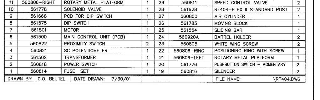
11 8. DRAWINGS AND PART LIST
12
13 9. ELECTRIC SCHEMATIC SCHEMATIC 1: (110V)
14 9. ELECTRIC SCHEMATIC (CONTINUED) SCHEMATIC 2: (220V)
15 10. PNEUMATIC SCHEMATIC
16 RT404-FLEX II WARRANTY Manufacturer warrants this product to the original purchaser for a period of one year from the date of purchase to be free from defects in material and workmanship, but not against damages by misuse, negligence, accident, faulty installation, abrasion, corrosion, or by not operating in accordance with factory recommendations and instructions. Manufacturer will repair or replace (at factory s option) free of charge, any component of the equipment thus found to be defective on return of the component PREPAID to the factory during the warranty period. In no event shall any liability or obligation of Manufacturer arising from this warranty exceed the purchase price of the equipment. This warranty is only valid if the defective RT404-FLEX II is returned as a complete assembly without physical damage. The manufacturer s liability, as stated herein, cannot be altered or enlarged except by a written statement signed by an officer of the company. In no event shall manufacturer be liable for consequential or incidental damages. A return authorization is required from I&J FISNAR INC. prior to shipping a defective unit to the factory. Manufacturer reserves the right to make engineering or product modifications without notice.
DCD Dual Cartridge Dispenser Operation Manual
 DCD Dual Cartridge Dispenser Operation Manual THIS PAGE HAS BEEN INTENTIONALLY LEFT BLANK 2 TABLE OF CONTENTS General Information Overview. 5 Limitations of Use... 6 Owners Responsibility.. 6 Safety Precautions.....
PPD-130 PERISTALTIC PUMP DISPENSER
 PPD130 Operating Manual Rev. D January 11 PPD130 PERISTALTIC PUMP DISPENSER OPERATING MANUAL 1 PPD130 Operating Manual Rev. D January 11 1.0 CAUTIONS AND WARNINGS CAUTION: EYE PROTECTION REQUIRED WARNINGS:
Techcon Systems TS5000 Series Rotary Valve
 10. SPARE PARTS AND ACCESSORIES 10.1 SPARE PARTS: The only spare parts available are: Fluid inlet fitting, O- ring and clean out screw. These items are included in the Valve cleaning kit part number: 5000-013-000
Techcon Systems TS7000 Series Interchangeable Material Path Rotary Valve
 Techcon Systems TS7000 Series Interchangeable Material Path Rotary Valve User Guide Copyright OK International CONTENTS Page number 1. Specifications 3 2. Unpacking and inspection 4 3. Description 4 4.
Automated I.V. Stand Cat. No OPERATOR S MANUAL. Operation& Maintenance Instructions. Raising the Standard of Care!
 Automated I.V. Stand Cat. No. 741314 OPERATOR S MANUAL Operation& Maintenance Instructions Raising the Standard of Care! Table of Contents Warranty....................... 2 Hardware.......................
ValveMate 7000 Controller Operating Manual
 A NORDSON COMPANY ValveMate 7000 Controller Operating Manual Steady Test Clear Time Set Fast Slow POWER RUN SETUP CYCLE A NORDSON COMPANY VALVEMATE 7000 Run Setup Purge Program Fast Slow Time Set Pressure
Techcon Systems TS5620 Series Diaphragm Valve. User Guide
 Techcon Systems TS5620 Series Diaphragm Valve User Guide CONTENTS Page number 1. Specifications - Horizontal Valve. 3 2. Specifications -Vertical Valve.. 4 3. Unpacking and Inspection 5 4. Description........5
MPT-250B SPECIFICATIONS AND OPERATING INSTRUCTIONS
 1. SAFETY The MPT-250B Wire Crimp Pull Tester is a force measurement device, and as such should be operated with due caution. Operators should wear safety glasses for eye protection because the crimp under
781Mini Series Spray Valve
 781Mini Series Spray Valve Operating Manual Electronic pdf files of Nordson EFD manuals are also available at www.nordsonefd.com You have selected a reliable, high-quality dispensing system from Nordson
Operating Instructions
 Operating Instructions WARNING: Do not attempt to assemble, connect to power source, or operate the Burrell Wrist-Action Shaker without first reading these instructions. Also assure that each person that
CRD600 Automatic Fitting Inserter
 CRD600 Automatic Fitting Inserter OPERATIONS MANUAL VERSION 2.3 LAST EDITED 12.07.2018 cleanroomdevices.com 1 Table of Contents Title Page.. 1 Table of Contents. 2 1.0 General Product & Safety Information...3
Techcon Systems TS5322 TS5322D Adjustable Mini Spool Valve. User Guide
 Techcon Systems TS5322 TS5322D Adjustable Mini Spool Valve User Guide CONTENTS Page number 1. Specifications..... 3 2. Unpacking and Inspection.... 4 3. Description........4 4. Theory of Operation.. 4
Hollywood Racks Sport Rider Hitch Rack Instruction Manual
 Hollywood Racks Sport Rider Hitch Rack Instruction Manual Model HR1200 3 Bike, 2 rec. Model HR1210 3 Bike, 1 ¼ rec. Model HR1400-4 Bike, 2 rec. Not to be used on any trailer, fifth wheel or vehicle being
Hydraulic Transmission Jacks
 Hydraulic Transmission Jacks Operating Instructions & Parts Manual Model Number Atd-7435 Atd-7436 Atd-7437 Capacity 1100 Lb. 2000 Lb. 3000 Lb. Model Atd-7435 Model Atd-7436 Model Atd-7437 Atd Tools Inc.
2K Piston Inserter. Operating Manual. Original Document. Electronic pdf files of Nordson EFD manuals are also available at
 2K Piston Inserter Operating Manual Original Document Electronic pdf files of Nordson EFD manuals are also available at www.nordsonefd.com Contents Introduction................................................................
SPEED & ROAD DEMON ELECTRIC CHOKE KIT #421440
 SPEED & ROAD DEMON ELECTRIC CHOKE KIT #421440 CHOKE INSTALLATION INSTRUCTIONS LIT702 Please make sure you have read and completely understand the instructions before you begin the installation. Keep in
CRD610 Automatic Fitting Inserter
 CRD610 Automatic Fitting Inserter OPERATIONS MANUAL VERSION 1.2 LAST EDITED 12.12.2018 cleanroomdevices.com 1 Table of Contents Title Page. 1 Table of Contents...2 1.0 General Product & Safety Information....3
Adjustable Angled Incline Conveyor Owners Manual with Operating Instructions
 Adjustable Angled Incline Conveyor Owners Manual with Operating Instructions Revision 012211 Table of Contents Basic Conveyor Features 3 Getting Started 4 Setting Up the Incline Conveyor 5 Belt Removal
Techcon Systems TS5000DMP Series Disposable Material Path Rotary Auger Valve. User Guide
 Techcon Systems TS5000DMP Series Disposable Material Path Rotary Auger Valve User Guide CONTENTS Page number 1. Specifications 3 2. Unpacking and Inspection.4 3. Description........4 4. Theory of Operation..
COMPRESSED AIR LOADER MODEL: AL-1
 COMPRESSED AIR LOADER MODEL: AL-1 Document: AL-1 IM 10-22-2011 TABLE OF CONTENTS Important Notices and Precautions 3 Quick Installation 4 Product Description 4 Principle of Operation 5 Unpacking and Inspection
ASSEMBLY / OPERATION INSTRUCTIONS. Low Profile Motorcycle Dolly
 ASSEMBLY / OPERATION INSTRUCTIONS 1,500LB CAPACITY Low Profile Motorcycle Dolly Model: 03-CG1500-01(B1) WARNING BEFORE USE PLEASE READ ALL WARNINGS AND INSTRUCTIONS TO PREVENT SERIOUS INJURY Drop-Tail
xqr41v Series Needle Valve
 xqr41v Series Needle Valve Operating Manual Electronic pdf files of Nordson EFD manuals are also available at nordsonefd.com You have selected a reliable, high-quality dispensing system from Nordson EFD,
ECLIPSE Laundry Dispenser Controller
 ECLIPSE Laundry Dispenser Controller Reference Manual Programming and Operation Online and downloadable Product Manuals and Quick Start Guides are available at www.hydrosystemsco.com Please check online
Read this entire manual before operation begins.
 Read this entire manual before operation begins. Record below the following information which is located on the serial number data plate. Serial No. Model No. Date of Installation Contents Specifications.............
FOR SIT-STAND WORKSTATION
 INSTALLATION MANUAL FOR SIT-STAND WORKSTATION Weight Capacity: 6.5-24.5 lbs. 6017180 Rev. B Contents Tools Required / Supplied Part Kits / Warnings/Disclaimers...2 Base Installation Clamp Mount Base Location...3
Operating Instructions and Parts Manual Long Chassis Service Jacks
 Operating Instructions and Parts Manual Long Chassis Service Jacks Models JSJ-3T/JSJ-5T/JSJ-10T WMH TOOL GROUP 2420 Vantage Drive Elgin, Illinois 60123 Part No. M-454430 Ph.: 800-274-6848 Revision A 8/05
Recumbent Hitch Rack Instruction Manual
 Recumbent Hitch Rack Instruction Manual Model 45816 2 receiver Model 45815 1 ¼ receiver Not to be used on any trailer, fifth wheel or vehicle being towed by another vehicle Weight Limit 125lbs/57 kg The
TABLE OF CONTENTS. Important Safety Information 3. Parts List 4
 1 TABLE OF CONTENTS Important Safety Information 3 Parts List 4 Assembling THERACK 5 7 How To Unfold THERACK 8 How To Fold THERACK 9 THERACK Levels 10 Warranty 11 2 IMPORTANT SAFETY INFORMATION IMPORTANT:
series USER MANUAL
 888 534-5994 4000 series USER MANUAL Contents Here s all the information you need for setting and operating your new Lathem time recorder. Service information is also included in this manual, in case any
MODEL G300 BRAKE BLEEDER
 MODEL G300 BRAKE BLEEDER Installation, Operation & Repair Parts Information Branick Industries, Inc. 4245 Main Avenue P.O. Box 1937 Fargo, North Dakota 58103 REV120716 P/N: 81-0035H THIS PAGE INTENTIONALLY
MODEL EF Full Circle Tire Spreader
 MODEL EF Full Circle Tire Spreader Installation, Operation & Repair Parts Information Branick Industries, Inc. 4245 Main Avenue P.O. Box 1937 Fargo, North Dakota 58103 REV. 062917 P/N: 81-0050C CAUTION
CLEAN ROOM DEVICES, LLC "WHERE TUBING AND FITTINGS COME TOGETHER"
 CLEAN ROOM DEVICES, LLC "WHERE TUBING AND FITTINGS COME TOGETHER" CRD600 Automatic Fitting Inserter OPERATIONS MANUAL VERSION 2.1 LAST EDITED 7.25.14 DOCUMENT NUMBER 001 cleanroomdevices.com 1 Table of
Watts Series CSM-91. Grooved/Flanged Flow Measurement/Balancing Valves. Installation and Operating Instructions. Table of Contents. 1.
 Watts Series CSM-9 Grooved/Flanged Flow Measurement/Balancing Valves Installation and Operating Instructions IS-CSM-9 Table of Contents Item Description Page. Installation of Valve Angle Design 2. Installation
Hydraulic Wheel Dolly
 Hydraulic Wheel Dolly Operating Instructions & Parts Manual Model Number HW93765 Capacity 3/4 Ton Made in the U.S.A. This is the safety alert symbol. It is used to alert you to potential personal injury
CLEAN ROOM DEVICES, LLC "WHERE TUBING AND FITTINGS COME TOGETHER"
 CLEAN ROOM DEVICES, LLC "WHERE TUBING AND FITTINGS COME TOGETHER" CRD600AF Automatic Fitting Inserter With Auto Feed OPERATIONS MANUAL (Shown with optional alcohol dispenser) 1 VERSION 1.1 LAST EDITED
accidents which arise due to non-observance of these instructions and the safety information herein.
 20 TON HYDRAULIC JACK Model: 7525 CALIFORNIA PROPOSITION 65 WARNING: You can create dust when you cut, sand, drill or grind materials such as wood, paint, metal, concrete, cement, or other masonry. This
JET METER INSTRUCTIONS
 UNPACKING Please open and inspect your package upon receipt. Your package was packed with great care and all the necessary packing materials to arrive to you undamaged. If you do find an item that is broken
Internal MAP Water/Methanol Injection Controller ,
 Internal MAP Water/Methanol Injection Controller 30-3304, 30-3306 WARNING: Improper installation and/or adjustment of this product can result in major engine/vehicle damage! Use of this injection system
BC Brake Caliper. (i) MEX (55) QRO (442) MTY (81) DIST. AUTORIZADO
 MEX (55) QRO (442) MTY (81) DIST. AUTORIZADO") MEX (55) 5 6 QRO (44) 95 7 60 MTY () 54 0 BC Brake Caliper (i) FORM NO. L-0066-B-040 In accordance with Nexen s established policy of constant product improvement, the specifications contained in this
MEX (55) 5 6 QRO (44) 95 7 60 MTY () 54 0 BC Brake Caliper (i) FORM NO. L-0066-B-040 In accordance with Nexen s established policy of constant product improvement, the specifications contained in this
Loctite Spray Valve Controller Part Number EQUIPMENT Operation Manual
 Loctite Spray Valve Controller Part Number 1406023 EQUIPMENT Operation Manual Table of Contents 1 Please Observe The Following 3 1.1 Emphasized Sections 3 1.2 For your Safety 3 1.3 Unpacking and Inspection
MARCY Recumbent Bike PL-960
 NOTE: Please read all instructions carefully before using this product Table of Contents Safety Notice Hardware Identifier MARCY Recumbent Bike PL-960 Assembly Instruction Parts List Computer Warranty
Telescopic Transmission Jacks
 Telescopic Transmission Jacks Operating Instructions & Parts Manual Model Number BH7051 BH7055 (Air/Manual) Capacity 1/2 Ton 1/2 Ton SFA Companies 2006 10939 N. Pomona Ave. Kansas City, MO 64153 816-891-6390
Use and Care Guide. Part # SC SV-OS-BZ SC SV-OS-W Model #
 Part # SC-20-840-SV-OS-BZ SC-20-840-SV-OS-W Model # 51402241 51402242 Use and Care Guide LED SECURITY LIGHT Dusk to Dawn Questions, problems, missing parts? Call ETiSSL Customer Service 8 a.m. - 5 p.m.,
GEN-3 Super-duty Supercharger Shaft Kit PART# - RY17040-UK-6S5-3
 GEN-3 Super-duty Supercharger Shaft Kit PART# - RY17040-UK-6S5-3 We strongly recommend the use of a service manual to familiarize yourself with the various components and procedures involved with this
DEMON CARBURETOR MANUAL CHOKE KIT #421441
 DEMON CARBURETOR MANUAL CHOKE KIT #421441 CHOKE INSTALLATION INSTRUCTIONS LIT703 This manual choke kit is designed to be used on any Demon Carburetor with a choke tower. This covers the Road Demon Jr.
TRU-TIME ADJUSTABLE CAM GEAR Part Number: BK & BK
 TRU-TIME ADJUSTABLE CAM GEAR Part Number: 23-801BK & 23-802BK! WARNING: This installation is not for the mechanically challenged! If you are not mechanically inclined or do not understand the procedure
MODEL G300 Brake Bleeder
 MODEL G300 Brake Bleeder Installation, Operation & Repair Parts Information Branick Industries, Inc. 4245 Main Avenue P.O. Box 1937 Fargo, North Dakota 58103 Rev013107 P/N: 81-0035C CAUTION Before using
Model 340 Tune-Up Kit Instructions
 Model 340 Tune-Up Kit Instructions Jacobs P/N 019654 tune-up kit instructions Tune-up Kit Contents Illus. No. Jacobs P/N Part Name Quantity Per Kit 4 020229 Upper Seal Ring 3 5 001082 Center Seal Ring
RED23305 Owner s Manual
 RED23305 Owner s Manual 5 foot, 3-Point Mounted Snow Blower 270 West Park Avenue Huron, SD 57350 866-526-5682 Serial Number: Date of Purchase: Red Devil Snow Blower See Figure 1. 1. The Red Devil Snow
RENA AF371Feeder Operating Manual. Feeder. Operating Manual. Manual Part #: M AF371 Operations Rev
 Manual Part #: M-3022 Feeder AF371 Operations Rev. 3-16-04 1 RENA AF371 Feeder YOUR RENA AF371 IS DISTRIBUTED BY RENA SYSTEMS INC. SERVICE AND SUPPORT FOR THIS PRODUCT IS PROVIDED BY YOUR RENA DEALER.
Full View Flow Indicator
 Full View Flow Indicator Threaded and Flanged Process Connection Installation / Operation / Maintenance Manual P.O. Box 1116 Twinsburg, OH 44087 Phone: 330/405-3040 Fax: 330/405-3070 E-mail: view@ljstar.com
ASSEMBLY / OPERATION INSTRUCTIONS. Low Profile / Stand-Up Motorcycle Dolly
 ASSEMBLY / OPERATION INSTRUCTIONS 1,500LB CAPACITY Low Profile / Stand-Up Motorcycle Dolly Model: 03-CGPR1500-01(C) WARNING BEFORE USE PLEASE READ ALL WARNINGS AND INSTRUCTIONS TO PREVENT SERIOUS INJURY
Read this entire manual before operation begins.
 Read this entire manual before operation begins. Record below the following information which is located on the serial number data plate. Serial No. Model No. Date of Installation Contents Specifications.............
- C8. SINGLE AND MANIFOLD TYPE INJECTORS for dispensing fluid lubricants and greases not exceeding Lincoln ventmeter viscosity of 600 psi.
 SINGLE AND MANIFOLD TYPE INJECTORS for dispensing fluid lubricants and greases not exceeding Lincoln ventmeter viscosity of 600 psi. SPECIFICATIONS Minimum operating pressure 1850 psi [128 bar] Maximum
ELECTRIC ACTUATOR AND CONTROLLER FOR AKRON BUTTERFLY VALVES INSTALLATION INSTRUCTIONS
 ELECTRIC ACTUATOR AND CONTROLLER FOR AKRON BUTTERFLY VALVES INSTALLATION INSTRUCTIONS The electric actuator and controller is designed to operate current model Akron Style 7940, 7945, 7950 and 7960 Butterfly
The Da-Lite Difference.
 The Da-Lite Difference. Instruction Book for Boardroom Electrol DA-LITE SCREEN COMPANY, INC. 3100 North Detroit Street Post Office Box 137 Warsaw, Indiana 46581-0137 Phone: 574-267-8101 800-622-3737 Fax:
ECONOMAIR SERIES CYLINDERS
 OPERATOR S MANUAL INCLUDING: APPLICATION, LUBRICATION, INSTALLATION & SERVICE ECONOMAIR SERIES CYLINDERS 2XXX-XXX9-XXX RELEASED: 9-14-92 REVISED: 3-6-01 (REV. B) READ THIS MANUAL CAREFULLY BEFORE INSTALLING,
( Versions Available)
") STYLE 494 ELECTRIC LADDER PIPE INSTALLATION, OPERATING AND MAINTENANCE INSTRUCTIONS ( Versions Available) The following is intended to provide the basic instructions for installation, operating and maintenance
STYLE 494 ELECTRIC LADDER PIPE INSTALLATION, OPERATING AND MAINTENANCE INSTRUCTIONS ( Versions Available) The following is intended to provide the basic instructions for installation, operating and maintenance
Installation Manual TWM Performance Short Shifter Cobalt SS/SC, SS/TC, HHR SS, Ion Redline and Saab 9-3
 Page 1 Installation Manual TWM Performance Short Shifter Cobalt SS/SC, SS/TC, HHR SS, Ion Redline and Saab 9-3 Please Note: It is preferable to park on a flat surface, as you will have to engage and disengage
Read this entire manual before operation begins.
 Read this entire manual before operation begins. Record below the following information which is located on the serial number data plate. Serial No. Model No. Date of Installation Contents Specifications.............
BackPack Valve Actuator
 BackPack Valve Actuator Operating Manual Electronic pdf files of Nordson EFD manuals are also available at nordsonefd.com The Nordson EFD Pledge Thank You! You have just purchased the world s finest precision
DEMA MIXRITE PROPORTIONING PUMP MODELS 574 & CL & 575CL FOR CORROSIVE LIQUID CHEMICALS INSTALLATION INSTRUCTION.
 10% MixRite Pump I-871 Page 1 MODEL # INDUCTION RANGE%* TECHNICAL DATA TABLE Ability to turn off INDUCTION the chemical flow RANGE RATIO* while water is running OPERATING TEMPERATURE 574 3% to 10% 33/1
INSTALLATION & SERVICE INSTRUCTION MANUAL W.A. KATES FLOW CONTROLLERS FC VALVE MODELS E THRU M
 INSTALLATION & SERVICE INSTRUCTION MANUAL W.A. KATES FLOW CONTROLLERS FC VALVE MODELS E THRU M IMPORTANT 1. W. A. Kates flow rate controllers are designed to accurately regulate flows and are precision
Read this entire manual before operation begins.
 Read this entire manual before operation begins. Record below the following information which is located on the serial number data plate. Serial No. Model No. Date of Installation Contents Specifications.............
Hydraulic Clutch Jack
 Hydraulic Clutch Jack Operating Instructions & Parts Manual Model Number Atd-7404 Capacity 500 Lb. Atd Tools Inc. 160 Enterprise Drive, Wentzville MO 63385 Printed in China ATD7404-M0 05/07 Save these
PL900 ILLUMINATOR. Fiber-Lite. Operation Manual. Setup. Fiber Optic Connection A PRODUCT OF DOLAN-JENNER INDUSTRIES. Voltage Selection:
 PL900 ILLUMINATOR A PRODUCT OF DOLAN-JENNER INDUSTRIES Setup Voltage Selection: Operation Manual Read and review the instructions on the label covering the power entry module and the instructions in this
POWER GEAR SLIDE-OUT MANUAL
 POWER GEAR SLIDE-OUT MANUAL Operation Guide FLUSH FLOOR SLIDE-OUT SYSTEM FOR AMERICAN COACH PRODUCTS 82-S0220-01 Rev. 1 AMERICAN COACH SLIDE-OUT MANUAL FLUSH FLOOR SYSTEM TABLE OF CONTENTS SECTION PAGE
EQUIPMENT Operation Manual. Loctite RB10 Rotary Dispense System Part Number
 EQUIPMENT Operation Manual Loctite RB10 Rotary Dispense System Part Number 1635546 1 Table of Contents 1 Please Observe The Following 3 1.1 Emphasized Sections 3 1.2 For Your Safety 1.3 Inspection 3 1.4
INSTALLATION NOTES: nbeckon-26
 INSTALLATION NOTES: nbeckon-26 1. Caution and Safety Instructions Qualified personnel must install and/or service product in a manner consistent with its intended use and in compliance with the National
LAYCOCK SYSTEMS, INC N. 43 rd Street Tampa, FL
 LAYCOCK SYSTEMS, INC. 1601 N. 43 rd Street Tampa, FL 33605-5937 LAYCOCK Phone: 813-248-3555, Fax: 813-242-0514 CROWN MOTOR E-Mail: sales@laycocksystems.com MOTOR WINDING Website: www.laycocksystems.com
SLR / SLR-S/N. Instruction Manual. Walrus America Inc
 SLR / SLR-S/N Instruction Manual Walrus America Inc 1. Installation and Connection 1.1. Pump Installation The pump should be sited in a well ventilated and frost-free position. The distance between pumps-motors
IV STANDS. Assembly, Usage and Maintenance INSTRUCTION MANUAL
 INSTRUCTION MANUAL IV STANDS Assembly, Usage and Maintenance Read and understand all of the instructions and safety information in this manual before operating this product. MAN-045 REV A 2018 MAC Medical,
Benron Equipment & supply, Inc.
 Benron Equipment & supply, Inc. Service Manual G5 Part Number 6-00A. and 6-00M Edition 0/008 Ez-Tex G5 Operational Instructions. Before attempting to use the G5 check material manufacturer for mixing and
Read this entire manual before operation begins.
 Read this entire manual before operation begins. Record below the following information which is located on the serial number data plate. Serial No. Model No. Date of Installation Contents Specifications.............
INSTRUCTION, GPT HAND PUMP KIT (BUCHER PUMP) INSTALLATION
 INSTALLATION") LIFT CORPORATION Sht. 1 of 27 DSG# M-15-13 Rev. A Date: 11/04/15 INSTRUCTION, GPT HAND PUMP KIT (BUCHER PUMP) INSTALLATION KIT P/N 296075-01 NEEDLE VALVE, ADJUSTABLE, SAE #6 P/N 906739-01 QTY. 1 CONNECTOR,
LIFT CORPORATION Sht. 1 of 27 DSG# M-15-13 Rev. A Date: 11/04/15 INSTRUCTION, GPT HAND PUMP KIT (BUCHER PUMP) INSTALLATION KIT P/N 296075-01 NEEDLE VALVE, ADJUSTABLE, SAE #6 P/N 906739-01 QTY. 1 CONNECTOR,
Hydraulic Wheel Dolly
 Hydraulic Wheel Dolly Operating Instructions & Parts Manual Model Number HW93766 Capacity 3/4 Ton Made in the U.S.A. This is the safety alert symbol. It is used to alert you to potential personal injury
Microscope light manual
 Microscope light manual LS-12 and LS-14 LS-12 LS-14 1/9 Content Overview... 3 Mounting... 4 Light adjustment... 5 Mirror... 6 Filters... 6 Replacing microscope light... 7 Technical data... 8 Troubleshooting...
FIXED DEPTH INSERTION METER INSTRUCTIONS
 UNPACKING Please open and inspect your package upon receipt. Your package was packed with great care and all the necessary packing materials to arrive to you undamaged. If you do find an item that is broken
Model No , -2, -3, -4, -5, , , -2, -3, -4, -5, and SL-V INJECTOR Series A
 8578 and 85782 Series A SINGLE AND MANIFOLD TYPE INJECTORS for dispensing fluid lubricants and greases not exceeding Lincoln ventmeter viscosity of 600 psi. SPECIFICATIONS Minimum operating pressure 850
Rectangular Door L-VAT with pneumatic actuator double acting
 Rectangular Door L-VAT with pneumatic actuator double acting This manual is valid for the products: 0 7 5 1 0 U A 2 4 0 0 0 1 4 character option code Size 10... 46 x 236 12... 50 x 336 Actuator 24... without
ALWAYS DISCONNECT DISPENSER FROM WATER SOURCE WHEN DISPENSER IS NOT IN USE.
 1060GAPRF With dilution selector 1060GAP OVERVIEW DEMA S MPD is a multiple product and dilution dispenser designed for use with SafeLink closed loop inserts. With its innovative patent pending QuickDock
SOLUTION STATION Instruction Manual
 SOLUTION STATION Instruction Manual WAXIE Sanitary Supply 9353 WAXIE Way San Diego, CA 92123 Phone: 800.995.4466 www.waxie.com TABLE OF CONTENTS Unpacking Instructions Disclaimer..... Warranty... Introduction...
Assembly Instructions
 www.rockymounts.com TandemMount R4 Installation Manual Guidelines/Restrictions: - This carrier is intended for Thule rectangular and Yakima round bars only. - Bicycles must be equipped with quick release
Service/Installation Manual Full Wall Slide Systems
 Service/Installation Manual Full Wall Slide Systems 7 East 7th Street Mishawaka, IN 65 888-9-57 Fax 57-56-67 www.powergearus.com 8-S079 Rev Page CONTENTS Page Major Components Full Wall Slide System Operation
Read this entire manual before operation begins.
 Read this entire manual before operation begins. Record below the following information which is located on the serial number data plate. Serial No. Model No. Date of Installation Contents Specifications.............
Mini Jacks Instruction Manual
 J11050-M0_062017 Instruction Manual MODELS: J11050, J11055-5 Ton Capacity J11100-10 Ton Capacity J11200-20 Ton Capacity This is the safety alert symbol. It is used to alert you to potential personal injury
Read this entire manual before operation begins.
 Rev. 12/12/2017 Read this entire manual before operation begins. Record below the following information which is located on the serial number data plate. Serial No. Model No. Date of Installation Contents
Long Chassis Hydraulic Service Jacks
 Long Chassis Hydraulic Service Jacks Operating Instructions & Parts Manual Model Number Atd-7390 Atd-7391 Capacity 5 Ton 10 Ton Atd Tools Inc. 160 Enterprise Drive, Wentzville MO 63385 Printed in China
AEROMOTIVE Part # /2 4.6L SOHC Ford Fuel Rail Kit INSTALLATION INSTRUCTIONS
 AEROMOTIVE Part # 14125 96-98 1/2 4.6L SOHC Ford Fuel Rail Kit INSTALLATION INSTRUCTIONS CAUTION: Installation of this product requires detailed knowledge of automotive systems and repair procedures. We
OPERATION AND PARTS MANUAL
 OPERATION AND PARTS MANUAL MODEL NUMBER : PART NUMBER : GTL 1110 1900-0510 SERIAL NUMBER : BAYNE MACHINE WORKS, INC. PHONE: (864) 288-3877 910 FORK SHOALS ROAD TOLL FREE: (800) 535-2671 GREENVILLE S.C.,
VW/AUDI MK7 VEHICLES
 Installation Manual P/N 1-301-1708-01 (STAGE 2+ FUEL KIT) P/N 1-301-1708-02 (STAGE 3+ FUEL KIT) VW/AUDI MK7 VEHICLES Warning: This installation is not recommended for a novice or the new guy in the shop.
MARCY Elliptical Machine PL-21930
 NOTE: Please read all instructions carefully before using this product Table of Contents Safety Notice Hardware Identifier MARCY Elliptical Machine PL-21930 Assembly Instruction Parts List Computer Warranty
Hydraulic Transmission Jack, Telescopic
 Operating Instructions & Parts Manual Hydraulic Transmission Jack, Telescopic Model 4000 400 (Air Operated) Capacity 000 lbs. 000 lbs. Model 4000 Model 400 U.S. Patent No. 6,02,377! This is the safety
SYSTEM CONTROL KIT. Model: CK-41F. Designed for use with the SWG Series Power Venter for controlling Natural Gas or L.P. Gas appliances.
 SYSTEM CONTROL KIT Model: CK-41F Designed for use with the SWG Series Power Venter for controlling Natural Gas or L.P. Gas appliances. ITEMS INCLUDED IN KIT: 1- Junction box with mounted pressure switch
SUBMERSIBLE MINI-PUMP
 SUBMERSIBLE MINI-PUMP Model 41287 Set up And Operating Instructions Diagrams within this manual may not be drawn proportionally. Due to continuing improvements, actual product may differ slightly from
INSTRUCTIONS DURA SHOT S SPRAYERS DIRECTIONS FOR OPERATING DURA SHOT S. 24 oz. DURA SURE SHOT S SPRAYER.
 DURA SHOT S SPRAYERS INSTRUCTIONS Refillable, reusable. Extra versatile. Pressurized by free air DURA SHOT S 24 oz. DIRECTIONS FOR OPERATING DURA SHOT S SPRAYERS 1) ALWAYS DEPRESSURIZE SPRAYER BEFORE REMOVING
Installation Instructions
 Installation Instructions Rock Crawler Roof Rack (Part # 76717) 07-Up Jeep Wrangler J/K 4Door For Technical Support/Warranty Information please call 310-762-9944 Smittybilt, 400 West Artesia Blvd, Compton,
4400-Lb. Capacity Pallet Jack
 Read carefully and understand all ASSEMBLY AND OPERATION INSTRUCTIONS before operating. Failure to follow the safety rules and other basic safety precautions may result in serious personal injury. Item#
User Manual. Posture+ Adjustable Base. For customer service call:
 User Manual Posture+ Adjustable Base For customer service call: 1-877-707-7533 1 IMPORTANT INFORMATION PLEASE READ THESE INSTRUCTIONS THOROUGHLY BEFORE USING THIS PRODUCT. PROPER OPERATION OF YOUR ADJUSTABLE
INSTRUCTION MANUAL. Rotary Unidirectional Piezoelectric Motor Evaluation Kit. (Model: UPM-28) Made in USA
 Made in USA") www.dtimotors.com INSTRUCTION MANUAL Rotary Unidirectional Piezoelectric Motor Evaluation Kit (Model: UPM-28) Made in USA Rev. 6/2/2017 Table of Contents 1.0 Introduction... 2 2.0 Properties... 3 3.0 Unpacking
www.dtimotors.com INSTRUCTION MANUAL Rotary Unidirectional Piezoelectric Motor Evaluation Kit (Model: UPM-28) Made in USA Rev. 6/2/2017 Table of Contents 1.0 Introduction... 2 2.0 Properties... 3 3.0 Unpacking