INSTRUCTION MANUAL_1219_ENGLISH SUPER ELF X3. Operating Instructions for DORNIER looms. Robustness Reliability Quality Productivity Versatility
|
|
|
- Aleesha Wade
- 5 years ago
- Views:
Transcription


1 INSTRUCTION MANUAL_1219_ENGLISH SUPER ELF X3 Operating Instructions for DORNIER looms Robustness Reliability Quality Productivity Versatility

2 WARNING! - Condensation could form on the Weft Feeder when it is moved from the cold environment of the warehouse to the warmer environment of the weaving room. Make sure that it is completely dry before connecting to power. - Provide proper information to the people operating the weft Feeders. - The installation, connection, adjustment, and maintenance of the Weft Feeder has to be performed by technically qualified personnel. - The Loom's main power switch MUST be switched OFF before any replacing or connecting operation. - Caution must be taken on the close vicinity of the Feeder. In normal working condition, it can start running without prior warning and the moving parts might cause injuries. - Repairing any electrical part of the unit has to be carried out by Roj s.r.l. authorized personnel. -Always use proper spare parts and accessories supplied by Roj s.r.l. - Roj s.r.l. disclaims all responsibility for the improper use of the Feeder different from what described in the chapter 1. General Information.
3 INDEX page 1. GENERAL INFORMATION Super Elf X3 description 3 Super Elf X3 Technical Data 3 Pulsar HP brake description 3 Technical data of Pulsar HP 3 Other information about Super Elf X3 3 Features and Characteristics 4 2. SETTING AND CONTROL ELEMENTS Front control elements 5 Back panel control elements 6 3. INSTALLATION AND CONNECTION Electric connections 7 Diagram connection of the Voltage Supply Box 8 4. SETTINGS AND OPERATION How to set working parameters 9 Insertion length 10 Reserve sensor 10 Filling tensioner (Pulsar HP) 11 Sensors sensitivity settings 13 Maintenance 14 Photocells automatic calibration 15 Photocells information 15 Weft length adjustment 16 Winding direction and coils pitch adjustment 17 Reserve loading (Full air threading, only with funnel) 18 Reserve loading (Half air threading) TROUBLESHOOTING SPARE PARTS Funnel 20 Eyelet holder 20 Pulsar HP 20 Voltage Supply Box 21 Feeder (with Plasma coated Spool body) 22 Feeder (with Chromed coated Spool body) 23 2
4 1. GENERAL INFORMATION Super Elf X3 description SUPER ELF X3 is a Weft Feeder with yarn separation and direct CAN-bus communication with the Loom Control. The new Permanent Magnet motor and the Reserve sensor allow very fast reaction and accurate yarn storage control on the spool body. The new and innovative barrier optical sensors guarantee best performances in dust environments and with very fine yarns. Super Elf X3 - Technical Data Power supply by means of the specific Roj Control Box: 100 V dc 24 V dc Weft feeding speed (pattern in advance info): max 2400 m/min Threading channel: 4.5 mm Yarn count range: 6 Nm - 10 dtex Noise level: < 70 db A Weight: 8 kg Working temperature: from 10 to 40 C Storage temperature: from 25 to +65 C Relative humidity: max 95% (not condensed) Pulsar HP brake description The Pulsar HP device, performs the following two functions: Breaking function: to reduce the tension pick to the weft when the same is stopped by the Electromagnet pin. This is to avoid the following problems: a. weft breakage at the end of the insertion b. weft loops or slack picks in the fabric. Pull back function: after the yarn cutting, yarn is pulled back into the nozzle. This is to avoid that the weft gets tangled in the next weft to be inserted by the contiguous nozzle. Technical data of Pulsar HP Cycles per minute: Reaction time: 7 ms Max torque: 11.5 Ncm Weft pull back length: max 35 mm Eyelet's diameter: 6 mm Other information about Super Elf X3 The Part Number (P/N) and the Serial Number (S/N) are printed on the CE label. 3
. o Storage detection with an integrated photocell (barrier system).")
5 Features and Characteristics o The Weft Feeder can be set for rotation S or Z depending on the yarn twist. o Yarn separation is adjustable from 0.7 mm to 2.2 mm. o Coils detection by means of photocells (Barrier system). o Storage detection with an integrated photocell (barrier system). o Input Weft breakage control through a photocell integrated in the Super Elf X3, or through external TFE6 weft Stop Motion device. o Weft length adjustment, by setting the spool body diameter and the number of coils to be released at each insertion. o Range of weft lengths: from 64 to 672 cm. Note: Weft lengths ranging from 87 to 96 cm CANNOT BE MEASURED. o CAN BUS communication protocol with the loom Control. o Pulsar HP brake control. o Full and half weft threading by means of a pneumatic system. o New Electromagnet design. o Reserve Storage position Photocell reliable also in dust environments. o Permanent Magnet motor for more accurate speed control, faster acceleration, full torque at all speeds and lower energy consumption. o Sealed motor, photocells housing and cable connections are IP63 Water Proof standard o New anti-balloon design with reclining Funnel simplifies maintenance and optimizes space requirements for multi-color applications. 4

6 2. SETTING AND CONTROL ELEMENTS Front Control elements 1 FUNCTION BUTTON It activates the Electromagnet and allows the following operations: a- Weft reserve removal. b- New weft reserve loading. c- Release of only one coil when the weft reserve is already on the Spool Body. d- Photocells calibration e- Reset of the fatal errors without switching OFF the main power. A SIGNALING LED When the weft feeder is powered, the led turns on if no faults are detected. In case of problems, the led blinks. Slow blinking in case of warnings, fast blinking in case of fatal errors. B ADJUSTMENT SCREWS FOR THE ELECTROMAGNET POSITION C, D, E ADJUSTMENTS SCREWS OF SPOOL BODY DIAMETER (Coil length) F PUSH BUTTON FOR SETTING OF WINDING DISC ROTATION DIRECTION AND COILS SEPARATION 5

7 Back panel control elements 1 CONNECTION OF AIR LINE INPUT 2 CONNECTION OF AIR LINE FOR FULL AIR THREADING Full air threading is possible only in combination with Funnel. If the feeder is fitted with eyelet holder, or without any balloon control, this connection must be closed with relevant plug that it is supplied with the feeder. 3 HALF THREADING BUTTON Insert the yarn into the eyelet and press the half threading button (3), whilst lightly holding the yarn. 4 FULL THREADING BUTTON Insert the yarn into the eyelet and press the full threading button (4), whilst lightly holding the yarn. 6
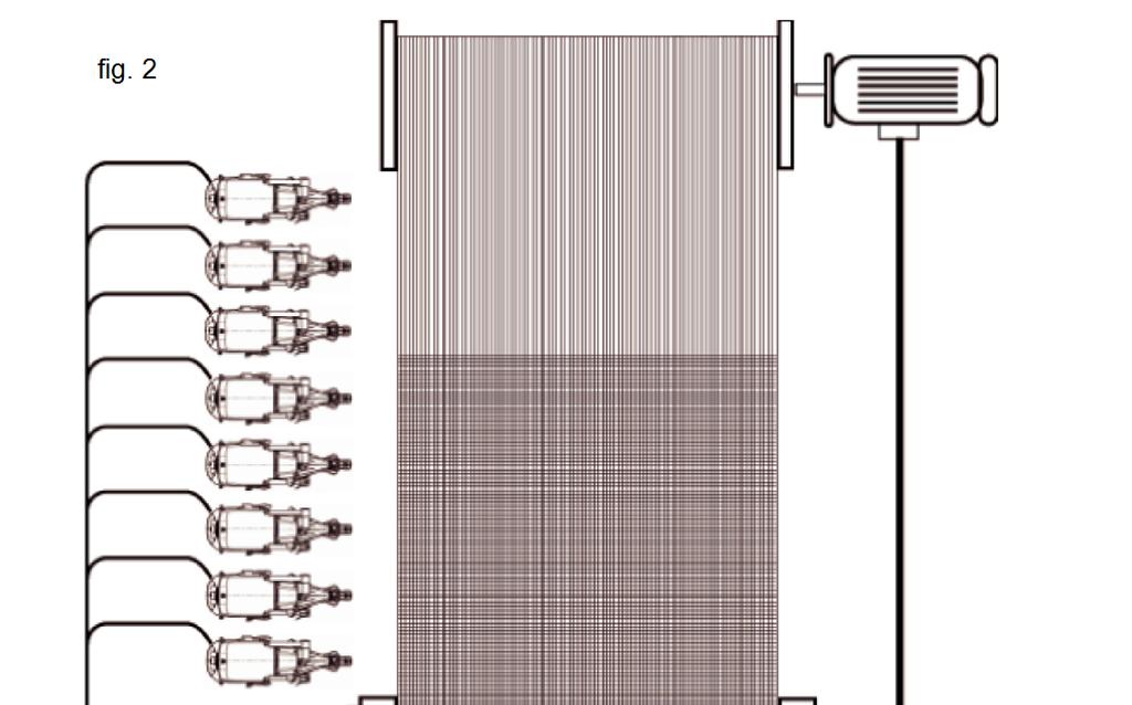
8 3. INSTALLATION AND CONNECTION Voltage Supply Box and Weft Feeder installation 1. Fix the Voltage Supply Box to the Stand by means of the proper brackets. Note: Minimum distance from the Box to the floor must be 20 cm. (see fig.1) 2. Install the Weft Feeders on the Stand by means of the existing clamps. Note: The feeders must be positioned on the stand according to the type of installation. It is important that yarn path is as straight as possible between the Feeders and the loom nozzles. 3. Place the Feeders' cables and the air tubes inside the tunnel of the Stand. Electrical connections 1. Connect the Feeder's cables to the Voltage Supply Box by following the numeric correspondence to the loom nozzles (Feeder working with the weft threaded in nozzle 1 must be connected to the position 1 of the Voltage Supply Box; etc.). 2. Connect the CAN BUS cable to the loom (see fig.2 page 8). 3. Feeder's Stand and Creel must be connected to the earth of the loom. 4. Connect the plug of the 3-phase power cord to the socket on the loom main control cabinet (MCC). See fig.2 page 8. Warning! The connection between the Voltage Supply Box and the 3-phase power supply network must always be as stated on the following page. In this way, the loom main switch performs also as main switch for the Weft Feeders (see fig. 2 page 8). Note: The Voltage values supplied to the Weft Feeders can be checked on the Voltage Supply Box connectors (see fig. 3 page 8). 7
9 8
. 2. The pulsar calibration cycle is then automatically performed.")
 is free to move and therefore avoid: Yarn tied to eyelet holder or any other machine part Yarn inserted into the")
10 4. SETTINGS AND OPERATION How to set working parameters 1. Turn the loom main switch ON. The feeders are now supplied with power and receive the setup data from the loom Control (wait for about one minute). 2. The pulsar calibration cycle is then automatically performed. If no faults occur, the signaling led, on the front side of the feeder, remains ON. In case of faults, the led blinks and a fault message is shown on the loom Dialog panel display. Note: Before switching the loom power ON, always verify that the pulsar fork (F) is free to move and therefore avoid: Yarn tied to eyelet holder or any other machine part Yarn inserted into the fabric and not cut The yarn can be kept firmly by loom controlled devices as these are synchronized with the Pulsar calibration function. To reset the error "Pulsar not calibrated", switch the loom OFF, make sure that the Pulsar fork is free to move, then switch the loom back ON. 3. According to the woven article, adjust the functioning parameters of Super Elf X3, which can be set on DORNIER loom Dialog panel (see picture below). 4. Press the icon to enter the feeder pages. 9


.")
11 Insertion length To set the number of coils (windings) to be released by the Feeder at each pick. Possible setting: 2 -> 16. Recommended setting: see note Note: the setting Insertion Length is dependent on the Reed width parameter which is under the Weft Insertion menu. It is recommended to make the Feeder operating with the Drum set to the wider diameter and releasing the minimum number of coils possible (see table below for reference). Reserve Sensor Automatic = ON Automatic = OFF When this is set to Automatic = ON, the Reserve Sensor automatically regulates the take-off point at a fixed position. Possible setting: Off, 0, 1, 2 10
 Recommended setting: 1 Reserve windings (to be set when Automatic = OFF) It sets the number of")
12 Off - Automatic position control deactivated 0 - Automatic position control activated with lower reserve storage 1 - Automatic position control activated with standard reserve storage 2 - Automatic position control activated with maximum reserve storage (the take-off point is nearby the stopper pin) Recommended setting: 1 Reserve windings (to be set when Automatic = OFF) It sets the number of coils to be wound on Spool body when a new Reserve is loaded. Set the highest number of coils possible, avoiding them to overlap each other nearby the stopper pin (the reserve has to be over 3/4 of the spool body length). Possible setting: 12 -> 68. Recommended setting: according to the yarn count, set the coils pitch as low as possible. Note: In case of different reserve position between Feeders, set with the same number of coils and make them equal by adjusting the coils pitch. Filling Tensioner (Pulsar HP) Set here the Yarn type Possible settings: fiber filament < 500dTex wool filament > 500dTex The Pulsar HP will automatically use the factory pre-settings according to the chosen yarn type Stroke This parameter allows set the stroke angle value: Possible setting: off brake disabled 1 minimum stroke angle 2 low stroke angle 3 middle stroke angle 4 high stroke angle 5 maximum stroke angle 11
13 Recommended setting: 2 it gives a low reduction of the end insertion tension peek. (The yarn speed reduction at the arrival is very low). 3 it gives a good reduction of the end insertion tension peek. (The yarn speed reduction at the arrival is low). 4 it gives a very good reduction of the end insertion tension peek. The yarn speed reduction is very high and the arrival is very irregular). Note: Use the "1" and "5" values only in extreme cases: 1 - when the important is to avoid to slow down the yarn at the arrival. (The reduction of the end insertion tension peak will be very low). 5 - to reduce the end insertion tension peek as much as possible. (The yarn speed reduction is very high and the arrival is very irregular). Duration This parameter set the duration of braking function. Possible setting: 0 the fork reach braking position at same time when the electromagnet pin stops the yarn at end of insertion 1 minimum braking anticipation 2 low braking anticipation 3 middle braking anticipation 4 high braking anticipation 5 maximum braking anticipation Recommended setting: 0, 1, 2 for filament yarns 2, 3, 4, 5 for fiber yarns and wool Force This parameter allows the user to choose between 5 force values: Possible setting: 0 minimum braking force 1 low braking force 2 middle braking force 3 high braking force 4 maximum braking force Recommended setting: Increase the braking force according to yarn size (Yarn count) 12

14 Filling Draw back This parameter allows to enable or disable the yarn filling draw back after yarn cut. It is also possible to choose how large angle to use to pull the yarn back. Possible setting: off disabled filling draw back 1 minimum angle for draw back 2 middle angle for draw back 3 maximum angle for draw back Recommended setting: Use mostly "2" and "3" values. Sensors sensitivity settings Reaction time of the Feed Sensor Set the sensitivity for the photocell with function as input yarn break sensor Possible setting: 2, 3, 4, 5 and OFF (OFF = Feed Sensor OFF) Recommended setting: 3 Note: increase the value in case of false yarn break stops Winding sensor Sets the sensitivity of the photocell which is controlling the outgoing coils. Possible setting: normal yarn / fine yarn Recommended setting: normal yarn Reserve sensor Sets the sensitivity of the photocell which is controlling Automatic Reserve Position. Possible setting: normal yarn / fine yarn Recommended setting: normal yarn 13
 with irregular insertion times.")

15 Length correction Avoids wrong weft length measurement due to the eventual overlapping of the coils on the Spool body. Possible setting: ON / OFF Recommended setting: ON Note: Set OFF in case of short picks (one coil less) with irregular insertion times. Double yarn sensor Controls the yarn break by means of an external sensor (Roj PIEZO sensor TFE6). Possible setting: ON / OFF Rotation direction To set the winding direction of the Feeder according to the yarn twist. Possible setting: Z / S Note: When changing the winding direction, the coils pitch has to be changed too. Maintenance Calibrate hardware Not used with Super Elf X3 Stopper / Pulsar test This test activates a test cycle on the pulsar that will move the pulsar fork according to the settings in the Filling tensioner menu. The Stopper electromagnet is also activated. Check reserve sensor Not used with Super Elf X3 14
 2.")
16 Photocells automatic calibration The Super Elf X3 is fitted with an automatic photocells calibration system. Proceed as follows: 1. Remove all the yarn from the spool body, and verify that the photocells glass and mirrors are clean (see below) 2. Press the Reserve push-button on the feeder side for about 10 seconds, till the LED makes a short blinking than remains steady ON: at this point the calibration is automatically performed by the feeder SW. Wait a few seconds, that reset the feeder by switching it OFF, than back ON. The automatic calibration is needed when replacing the feeder circuit board or one of the sensors groups. Note: if the calibration procedure is made with yarn on the spool body, or with glass -mirrors dirty, the feeder can go in alarm SYSTEM ERROR 4 and it is completely blocked. To unlock the feeder, remove the yarn from spool body, or the dust from glass mirrors, and make the automatic calibration again. If, after performing correctly the automatic calibration, the same error is still displayed on the loom Dialog panel, proceed as here below described: - Check the stopper pin position and distance from the spool body (see page 16) - Check the correct connection of the photocell circuit inside the spool body - Replace the top spool body sector (that includes the sensors) - Replace the stopper magnet housing - Replace the CPU board and make a new automatic calibration Photocells information The Super Elf X3 works with an automatic compensation system, to grant same level of reading signals, even when the dust stats to accumulate on the window glass of the optical sensors. The amount of dust accumulated it is indicated on relevant display page, as on example below: Note: this information for the Reserve sensor it is not yet implemented on loom display 15
. 3. Turn the Winding Disc until the eyelet is in the upper position. 4.")
 in order to move the sectors of the Winding Group to the requested reference")
17 Weft length adjustment The diameter of the Weft Feeder Spool Body must be set according to the indication shown on the loom Dialog panel display. Proceed as follows: 1. Loosen the screw B and raise the Photocells/Electromagnet Group. Fix it. 2. Loosen the both C socket head screws (3 mm socket). 3. Turn the Winding Disc until the eyelet is in the upper position. 4. Loosen the D1 socket head screw (3 mm socket). 5. Turn the Winding Disc until the eyelet is in the lower position. 6. Loosen the D2 socket head screw (3 mm socket) 7. Adjust the diameter of the Spool Body by turning the E socket screw (5 mm socket screw with the hole for D1 screw) in order to move the sectors of the Winding Group to the requested reference according to weft length to be inserted (see page 10). 8. Turn the Winding Disc until the eyelet is in the lower position. 9. Tighten the D1 and D2 socket head screws (3 mm socket) to block the fixed sectors (remember to center the hole on the screw head, points 3 and 5). 10. Check that the movable sectors are centrally positioned in respect with the fixed ones. 11. Tighten the two screws C to block the movable sectors. 12. Turn the Winding Disc and check that no movable sectors get in contact with the fixed ones; this is in order to avoid possible damages when the feeders is in operation. If the sectors get in contact, use the C screws to adjust the movable sectors. 13. Loosen the screw B and position the Photocells/Electromagnet group so that the distance between the Electromagnet and the Spool Body is about mm (see picture below on the right - use the special gauge supplied with the feeder). 14. Load the reserve as described on page Start up the loom and check if the length weft is as required. If it is too long, decrease a bit the spool body diameter. If it is too short, increase a bit the diameter. Note: Fixing torque recommended for the screws D1, D2 and C = 2.3 Nm ± 10% 16

18 Winding direction and coils pitch adjustment The winding direction (S or Z) must be adjusted according to the yarn twist. Correspondence is needed between the motor electric setting and the mechanical one of the Spool Body. Proceed as follows: 1. Press the yellow Separation push-button F placed in front of the Spool Body and simultaneously turn the Winding Disc until you hear a click (the yellow pushbutton is entered in a slot). 2. While keeping pressed this push-button, turn the Winding Disc up to the chosen position (the ceramic eyelet indicates the position). Release the push-button. Note: The coils pitch must be adjusted according to the yarn count. In case of working with Automatic Reserve set to OFF, set the Reserve Windings value on the loom Dialog panel by avoiding excessive accumulation of coils in front of the Spool Body. 3. Select the winding direction rotation on the loom Dialog panel: the magnet pin goes up allowing removal of the reserve from the Spool Body. In the meanwhile, the eyelet of the Winding Disc moves to the threading position. 4. Press the start push button 1, the Electromagnet pin goes down and the weft reserve is loaded. 17

19 Reserve loading (Full threading, only with funnel) 1. Press the start push-button 1 on the side of the feeder for more than 3 seconds: the Electromagnet pin goes up and the Winding Disc automatically moves to the threading position. 2. Release a few coils from the package and keep the yarn end near the input threading eyelet, than press the full threading button 4 to thread the weft through the feeder body out to the pulsar (if the old reserve is still on the spool body it will be automatically blown out). 3. Press the key in the front of the feeder a second time: the Electromagnet goes down and the Feeder loads the reserve. Weft reserve repair (Half threading) If during the Feeder operation, a weft breakage occurs at Feeder's entry, proceed as follows: 1. Release a few coils from the package and keep the yarn end near the input threading eyelet, than press the half threading button 3, so that the weft is blown to the output of the winding disk without affecting the existing reserve on the Spool Body. This operation allows the weft to be knotted to the existing reserve. 2. Press the start push-button 1 on the front of the feeder in order to reset the weft breakage error. The feeder will restore the complete weft reserve. 18
20 5. TROUBLESHOOTING Description All error messages from Super Elf X3 are shown on the display of Loom Dialog panel. Note: Details to fault analysis and fault repair are possible to find in the Dornier Documentation "Dialog Panel Ergo Weave" in chapter 4 "Messages" The Feeder will also give an alarm by means of the signaling LED (see page 4). The LED is steady ON during the normal operation of the Feeder. It is fast flashing in case of Heavy Alarms (i.e. the feeder cannot continue to work), or it is slow flashing in case of Warning Alarms (i.e. the feeder can continue to work, but some maintenance or checking is required) In case the loom Control panel will display Feeder n. SYSTEM ERROR 4 please refer to the Automatic photocells calibration described on page
21 6. SPARE PARTS 20
22 21
23 22
24 23
USER'S GUIDE and Spare Parts Drawings GENERIC APPLICATIONS
 Super ELF-X2 USER'S GUIDE and Spare Parts Drawings GENERIC APPLICATIONS SUPER ELF X2 WARNING! - Condensation could form on the Weft Feeder when it is moved from the cold environment of the warehouse to
HD-X2. Operating Instructions. Ref. No H /1232
 english HD-X2 Operating Instructions IRO AB Box 54 SE-523 22 Ulricehamn SWEDEN Tel: (+46) 32 297 00 Fax: (+46) 32 298 00 info@iro.se www.iroab.com Contents HD-X2 Contents... Safety...2 Technical specifications...3
Operating Instructions
 english Ref. No. 40-8939-2001-01/1333 40-8939-2101-01/1333 Operating Instructions Luna X3, Chrono X3, XD X3, XD X2, HD X2 ROJ Srl Via Vercellone 11 IT-13900 Biella Tel: (+39) 015 84 80 111 Fax: (+39) 015
Observe all necessary safety precautions when controlling the soft starter remotely. Alert personnel that machinery may start without warning.
 Introduction OPERATING INSTRUCTIONS: MCD REMOTE OPERATOR Order Codes: 175G94 (for MCD 2) 175G361 + 175G9 (for MCD 5) 175G361 (for MCD 3) 1. Introduction 1.1. Important User Information Observe all necessary
Control unit for Strip Thickness Gauges with nominal size setting by stepper motor Operating Instructions
 Control unit for Strip Thickness Gauges with nominal size setting by stepper motor FS4-PLC Operating Instructions FS4P-E1 erstellt am 15.4.2002 freigegeben am Bemerkungen Rev.1 Seiten: Name: Rietdorf Name:
Dusty / Dusty Ex. Low-Cost Broken Bag Detection. Operating Instructions. SWR engineering Messtechnik GmbH
 EN Dusty / Dusty Ex Operating Instructions Low-Cost Broken Bag Detection SWR engineering Messtechnik GmbH CONTENTS Page 1. Introduction.............................................................. 3 1.1
ELECTRONIC CONE WINDING MACHINE FOR CONTINUOUS BULKING AND SHRINKAGE MOD. VA-2
 ELECTRONIC CONE WINDING MACHINE FOR CONTINUOUS BULKING AND SHRINKAGE MOD. VA-2 Designed for continuous bulking and shrinkage ELECTRONIC CONE WINDING MACHINE mod. VA-2 Designed for continuous bulking and
INSTALLATION INSTRUCTIONS ALL JOHN DEERE SYSTEMS
 2 3 6 7 1 REAR 4 5 HELPFUL TOOLS Drill and Drill Bit for 3/8 Bolt 3/8 Ratchet with 9/16 Socket NEED HELP? Call our Product Support team at 888-512-4890. STEP 1 PREPARE BASE UNIT Slide the boom height base
UNIVERSAL AUTOMATIC MACHINE FOR WINDING STIFF AND ELASTIC RIBBON ONTO CORES, FLANGED CORES, SPOOLS AND FLAT PACKS
 UNIVERSAL AUTOMATIC MACHINE FOR WINDING STIFF AND ELASTIC RIBBON ONTO CORES, FLANGED CORES, SPOOLS AND FLAT PACKS Fully automatic, extremely versatile machine designed to produce a variety of different
POLE STAR PRO. Installation and instruction manual.
 POLE STAR PRO Installation and instruction manual. POLE STAR PRO is an automatic chrono and rev counter with a LED bar and Shift light which can be set, an indispensable instrument for drivers of: Go Karts
LP Series Label Feeders
 LP Series Label Feeders LPF01-001, LPF11-001 Product Guide All rights reserved Revision 6 18 June 2014 0620D-E001 LPF01-001, LFP11-001 Product Guide Hover-Davis, Inc. has checked the contents of this printed
User Manual Solar Charge Controller 3KW
 User Manual Solar Charge Controller 3KW Version: 1.3 CONTENTS 1 ABOUT THIS MANUAL... 1 1.1 Purpose... 1 1.2 Scope... 1 1.3 SAFETY INSTRUCTIONS... 1 2 INTRODUCTION... 2 2.1 Features... 2 2.2 Product Overview...
Pulsar EXtreme CLA 1500C
 www.mgeups.com MGE UPS SYSTEMS Pulsar EXtreme CLA 500C Installation and user manual 503998EN/AA - Page Introduction Thank you for selecting an MGE UPS SYSTEMS product to protect your electrical equipment.
USERS MANUAL MCD REMOTE OPERATOR
 USERS MANUAL MCD REMOTE OPERATOR Order Code: 175G9004, 175G3061 Contents Contents Introduction...2 Important User Information...2 General Description...2 Symbols Used in this Manual...2 Installation...3
GENERAL SAFETY... 3 PARTS LIST...
 Rev 17a 1 GENERAL SAFETY... 3 PARTS LIST... 4 GTR100... 4 GTR058... 5 TECHNICAL SPECIFICATIONS... 6 FEATURES:... 6 QUICK INSTALLATION GUIDE... 7 GATE ARM INSTALLATION... 8 BEFORE YOU START... 8 INSTALLATION
RS-110 Rainfall Sensor Installation Guide
 RS-110 Rainfall Sensor Installation Guide for XR440 and XR5 Data Loggers September 2015 Revision 1.1 1 Disclaimer The following warranty and liability disclaimer apply to this product. PACE SCIENTIFIC
Portable Metal Detectors By: MODEL P-4000 MANUAL PORTABLE
 MODEL P-4000 PORTABLE METAL DETECTOR MODEL P-4000 MANUAL PORTABLE All solid state circuitry. Factory direct repair service. Two year warranty RENS Metal Detectors reserves the right to make changes in
VECTRIX VX-2 SERVICE MANUAL. Version 1.0/May 2011 VECTRIX, LLC
 www.vectrix.com CONTENTS SECTION A: Tools 1 Tools Needed SECTION B: Mechanical Parts 1 Front Fairing 2 Front Console Cover 3 Speedometer Cover 4 Front Vertical Panel Cover-Lower 5 Front Vertical Panel
OPERATION MANUAL Common for All models. Weft Sensor (Weft Break Detection) AS - 35 A - 35 MSD10-24 (PNP/NPN)
 AS - 35 A - 35 MSD10-24 (PNP/NPN)") OPERATION MANUAL Common for All models Weft (Weft Break Detection) A - 35 MSD10-24 (PNP/NPN) Beta Computronics pvt. Ltd. 10/1 IT Park, Parsodi, Nagpur-440022 (MS), INDIA. Phone :+91-712-2227125, 2240122
OPERATION MANUAL Common for All models Weft (Weft Break Detection) A - 35 MSD10-24 (PNP/NPN) Beta Computronics pvt. Ltd. 10/1 IT Park, Parsodi, Nagpur-440022 (MS), INDIA. Phone :+91-712-2227125, 2240122
TOWA SEIDEN INDUSTRIAL CO., LTD.
 INSTRUCTION MANUAL SOUNDING LEVEL METER MODEL: TLX-120AP/200AP Meanings of indications for safety used in this Instruction Manual are as follows. WARNING: Indicates that improper handling assumes the risk
User Manual Rittal PMC UPS 6kVA
 User Manual Rittal PMC UPS 6kVA Germany Rittal GmbH & Co. KG Auf dem Stützelberg D-35745 Herborn Tel.: ++49-27 72-5 05-0 Fax: ++49-27 72-5 05-23 19 Internet: www.rittal.de 26 Contents 1. Introduction...
AOYUE INT. Advanced Repairing System NT 701A++ INSTRUCTION MANUAL
 AOYUE NT 701A++ INT Advanced Repairing System INSTRUCTION MANUAL Thank you for purchasing Aoyue Int701A++ Repairing System. It is important to read the manual before using the equipment. Please keep manual
SDOMEO51MV USER MANUAL. Portable Rugged PTZ Cameras
 SDOMEO51MV USER MANUAL Portable Rugged PTZ Cameras Table of Contents ABOUT THE PRODUCT... 3 Features... 4 Functions... 5 Technical Data... 8 PREPARATION... 10 Dip Switch... 10 Initial Power On Test...
USER INSTRUCTIONS FOR SLIDING DOORS
 ENGLISH USER INSTRUCTIONS FOR SLIDING DOORS SL3L LIGHT SL4A ADVANCED SL5A ADVANCED SL5H HEAVY SLTA TELESCOPIC-ADVANCED SL4E EMERGENCY SL5E EMERGENCY SL5B BIG SLTE TELESCOPIC-EMERGENCY FACE S.p.A. Viale
SMC BATTERY CHARGER USER S MANUAL SMC USER S MANUAL
 SMC BATTERY CHARGER SMC 1 INDEX 1 INDEX... 1 2 INTRODUCTION... 2 2.1 INTRODUCTION AND REFERENCES... 2 2.2 GLOSSARY... 2 2.3 DATA LABEL... 2 2.4 HOW TO USE THE USER'S MANUAL... 2 2.5 RESPONSIBILITY DISCLAIMER...
Congratulations. You ve just purchased the most advanced flasher available on the market today. This
 Congratulations. You ve just purchased the most advanced flasher available on the market today. This relay-isolated, solid-state module is designed to be installed into vehicles with a positive switched
2020 Dual Tabber Operation Manual
 2020 Dual Tabber Operation Manual Revision 1.2 10 Clipper Road 10/24/2006 West Conshohocken, PA 19428-2721 Tel : 800-523-0320 / 610-825-6205 Fax: 610-825-1397 www.secap.com Index SECTION 1 Introduction
Operating Manual. D3D Innovations Limited. 7 Kings Road, Wrington, Bristol, BS40 5LW, UK.
 Operating Manual FILAMENT WINDER D3D Innovations Limited 7 Kings Road, Wrington, Bristol, BS40 5LW, UK www.filafab.co.uk www.d3dinnovations.com www.filafab.co.uk Copyright 2016 by D3D Innovations Limited
Envirotainer RAP e2 Container Operations Manual
 Operations Manual This manual is valid for: RAP container, P/N 140010R-() Version 1.5: 2016-04-15 www.envirotainer.com Operations Manual RECORD OF REVISION RECORD OF REVISION VER. NO. ISSUE DATE REVISION
MG300 USER GUIDE. Ver. 3.2 INSTALLATION OPERATION AND MAINTENANCE MANUAL OF THE GEARLESS MG300.4, MG300.6, MGV30.4 AND MGV30.6
 MG300 USER GUIDE INSTALLATION OPERATION AND MAINTENANCE MANUAL OF THE GEARLESS MG300.4, MG300.6, MGV30.4 AND MGV30.6 Ver. 3.2 MONTANARI GIULIO & C. S.r.l. 41100 MODENA (Italy) Via Bulgaria,39 Tel. +39
CF-10 Option Operating Instructions
 CF-10 Option Operating Instructions for High-Low Track Sensors with Vibratory Bowl Single Feed Selection Version 1.2 May 27, 2009 Prepared by GPD Global Documentation Department Copyright (C) 2009 GPD
Modix Big-60 Assembly Manual Part 2
 Modix Big-60 Assembly Manual Part 2 Version 1.0, October 2017 Menu 1. Motors & End Stop Wiring... 3 2. Controller Wiring Check... 6 3. Extruder Wiring... 7 4. Electronic Box Cover... 9 5. Filament Sensor...
SensoStar C. Installation and Operating Instructions Heat Meter Calculator Heat/Cooling Meter Calculator Cooling Meter Calculator
 Installation and Operating Instructions Heat Meter Calculator Heat/Cooling Meter Calculator Cooling Meter Calculator SensoStar C DE-18-MI004-PTB037 (MID heat) DE-18-M-PTB-0049 (national German cooling)
User Manual V1.1 OptiFlex 1100 / OptiFlex 2000
 User Manual V1.1 OptiFlex 1100 / OptiFlex 2000 Uninterruptible Power Supply System Table of Contents 1. Important Safety Warning 2 1-1. Transportation 2 1-2. Preparation 2 1-3. Installation 2 1-4. Operation
Wallbox Commander. User Guide WBCM-UG-002-EN 1/11
 Wallbox Commander User Guide 1/11 Welcome to Wallbox Congratulations on your purchase of the revolutionary electric vehicle charging system designed with cuttingedge technology to satisfy your daily needs.
Service Manual BLACK DIAMOND SERVICE MANUAL. V.160 November
 BLACK DIAMOND SERVICE MANUAL V.160 November 2011 www.montrealchargeur.com www.battelec.ca www.doctorfleet.com Page 1/30 1. SAFETY PRECAUTIONS 1 Before to start using the Black Diamond Charger, read these
G-0-10, Plaza Damas, Sri Hartamas KL Malaysia Tel: Fax:
 Table of contents: 1- Introduction 2- Remotes manual 3- Important features of CTS (Car Trace System) mobile system 4- Important features of system at CTS website 5- Package contents 6- Different modes
LINEAR ACTUATOR MODULE Page 5-1. Table Of Contents
 LINEAR ACTUATOR MODULE Page 5-1 Table Of Contents Section Description Page # 5. Linear Actuator Module... 5-2 5.1 Description... 5-2 5.2 Operation... 5-2 5.2.1 Sensors... 5-3 5.2.1.1 Linear Sensor... 5-3
Pulsar EXtreme 2200C / 3200C
 www.mgeups.com MGE UPS SYSTEMS Pulsar EXtreme 00C / 300C Installation and user manual P O W E R P R O V I D E R L E I B E R R U P T N T N I E U T H 3400753EN/AA - Page Introduction Thank you for selecting
Sensors W2 and E2 are optional. Installation guide, 'Pickle Fork' Back-and-Forth Model Train Controller
 Installation guide, 'Pickle Fork' Back-and-Forth Model Train Controller Azatrax model PFRR-NTO This controller can automate a single track 'back-and-forth' model train layout -- or, one train can travel
Operator s Manual Series ACTS Automatic Closed Transition Transfer Switches 150 through 4000 amps A. Rating Label.
 Operator s Manual 7000 Series ACTS Automatic Closed Transition es 150 through 4000 amps TABLE OF CONTENTS section-page INSTALLATION... 1-1 Mounting and Line Connections... 1-1 Auxiliary Circuits and Harness...
Model 8000XL OPERATOR MANUAL
 Model 8000XL OPERATOR MANUAL DORAN SCALES, INC. 1315 PARAMOUNT PKWY. BATAVIA, IL 60510 1-800-262-6844 FAX: (630) 879-0073 http://www.doranscales.com MANUAL REVISION: 1.0 MAN0191 10/3/2005 INTRODUCTION
Ultrasonic heat meter
 Ultrasonic heat meter Installation and user guide Flow sensor-vmc-p Energy integrator Compact heat meter Temperature senor CONTENTS Kapitel Please read this manual prior to installation Page 3 2! T! Important
The RCS-6V kit. Page of Contents. 1. This Book 1.1. Warning & safety What can I do with the RCS-kit? Tips 3
 The RCS-6V kit Page of Contents Page 1. This Book 1.1. Warning & safety 3 1.2. What can I do with the RCS-kit? 3 1.3. Tips 3 2. The principle of the system 2.1. How the load measurement system works 5
We offer subject to prior sale:
 textile machinery, trade, spare parts, evaluations & technical service NEWSLETTER 41 2017 Weaving Machines We offer subject to prior sale: HOTTEST FALL OFFER Item#005345 2 DORNIER JACQUARD LOOMS - HTVS
2017 TigerStop, LLC. Installation Guide AUTOMATION. February 2017 Mk1
 2017 TigerStop, LLC Installation Guide AUTOMATION February 2017 Mk1 1 Sensor Clip Safety Box Kill Switch (attached) I/O Panel Controller Cable Sensor Bracket Locking Handles 2 pin connector w/ pigtail
DIN RAIL FIBER ENCLOSURE
 USER MANUAL JPM397A, JPM398A DIN RAIL FIBER ENCLOSURE 24/7 AT OR VISIT BLACKBOX.COM TABLE OF CONTENTS 1. SPECIFICATIONS... 3 2. OVERVIEW... 4 2.1 Description...4 2.2 What s Included...4 2.3 Part Numbers...4
Pressure Sealer ES-5000 ES User Manual. <Rev >
 ES-5000 User Manual 1 1. Introduction Table of Contents 2. Installation 3. Features 1) Specifications 2) General views 4. How to Operate 1) Form Preparation 2) Loading forms 3) Start 4)
DIGITAL RCD(ELCB) TESTER
 TESTER") INSTRUCTION MANUAL DIGITAL RCD(ELCB) TESTER KEW 5410 R KYORITSU ELECTRICAL INSTRUMENTS WORKS, LTD. Contents 1. Safety Warnings.... 1 2. Procedure of removing Cover. 3 2-1 Method of removing the Cover.
INSTRUCTION MANUAL DIGITAL RCD(ELCB) TESTER KEW 5410 R KYORITSU ELECTRICAL INSTRUMENTS WORKS, LTD. Contents 1. Safety Warnings.... 1 2. Procedure of removing Cover. 3 2-1 Method of removing the Cover.
Product manual Oil Streak Sensor INTRODUCTION CONSTRUCTION. Master Sensor
 Product manual Oil Streak Sensor INTRODUCTION Oil streak sensors are designed to detect traces of oil travelling through air tubes, down to flows as low as 5mm 3 /min. The product utilizes a master and
INSTALLER MANUAL USER MANUAL. Contents
 Installation & user manual two way Contents INSTALLER MANUAL Important information General 1. Technical data 2. Description Installation: 1. Positioning the unit 2. Connection. 3. Parts description. 4.
Operating instructions Flow monitor SI / / 2013
 Operating instructions Flow monitor SI0558 706335 / 00 03 / 2013 Contents 1 Preliminary note...3 1.1 Explanation of symbols...3 2 Safety instructions...3 3 Functions and features...4 3.1 Applications...4
Operating manual UPS - System
 Operating manual UPS - System POWERMASTER M MIL 1000VA 7Min. BAX 3330 E UPS-Division Issued 15. August 2006 JOVYATLAS JOVYATLAS Elektrische Umformtechnik GmbH Groninger Straße 29-37 D-26789 Leer/Ostfriesland
INSTALLATION MANUAL AP60B INSTALLATION MANUAL
 INSTALLATION MANUAL 2. TOOLS REQUIRED The following is a list of tools required to properly install the cruise control. While this unit may be installed without some of the tools listed, it is recommended
Operating instructions Flow monitors SI / / 2010
 Operating instructions Flow monitors SI5004 UK 704339 / 02 08 / 2010 Contents 1 Safety instructions 3 2 Functions and features 4 2.1 Application area 4 2.2 Operating principle flow monitoring 4 3 Installation
The Chameleon Trac II Patent Pending M-Series User s Manual
 The Chameleon Trac II Patent Pending M-Series User s Manual YOU MAY ALSO VIEW OUR GENERAL OPERATION VIDEO ONLINE AT: www.marionbrush.com Please read entire manual prior to using this system. Page 1 The
Inlet Controller TC5-ITA USER'S MANUAL. M rev. 02 K rev. 00
 Inlet Controller TC5-ITA USER'S MANUAL M 890-00047 rev. 02 K 895-00458 rev. 00 TABLE OF CONTENTS PRECAUTIONS... 3 FEATURES... 4 LOCATION OF THE CONTROLS... 5 Status Leds...5 Internal Switches...6 INSTALLATION
GARAGE DOOR OPENER OWNER S MANUAL S3/S4
 GARAGE DOOR OPENER OWNER S MANUAL S3/S4 Features! Locking door during power failure: If power failure occurs while the door is operating, the door can be released by pulling the clutch down, allowing
S TROBE BEACO N INSTALLATION & OPERATION MANUAL MODEL 92XXX 12 JOULE MODEL 95XXX 15 JOULE MODEL 98XXX 8 JOULE MODEL 99XXX 20 JOULE FULL RANGE
 INSTALLATION & OPERATION MANUAL FULL RANGE SERIES 90 MODEL 92XXX 12 JOULE MODEL 95XXX 15 JOULE MODEL 98XXX 8 JOULE MODEL 99XXX 20 JOULE FULL RANGE S TROBE BEACO N IMPORTANT: Contents: Introduction... 2
Operating Instructions. Angle Seat Control Valve. Type 7020
 Operating Instructions Angle Seat Control Valve Type 7020 With: Digital Positioner Type 8048 Electro-pneumatic Positioner Type 8047 Pneumatic Positioner Type 8047 Version: 02/2006 Manual-7020e.doc Art.-No:
All of the control valves that we install the Mk. 16IQ positioner on are factory calibrated for proper operation prior to shipment.
 1 Troubleshooting The first thing you need is information... Try to find out what is wrong and why. Getting a serial number (found on the valve tag (see above)) and application parameters are always helpful
MODEL 520 REMOTE START ENGINE MANAGEMENT SYSTEM
 MODEL 520 REMOTE START ENGINE MANAGEMENT SYSTEM DSE 520 ISSUE 4 4/4/02 MR 1 TABLE OF CONTENTS Section Page INTRODUCTION... 4 CLARIFICATION OF NOTATION USED WITHIN THIS PUBLICATION.... 4 1. OPERATION...
CHROME ALLEY CAT L.E.D. FUEL & BATTERY GAUGE 7381
 CHROME ALLEY CAT L.E.D. FUEL & BATTERY GAUGE 7381 Thank You For Choosing Küryakyn! Protect yourself and others from potential injury and property damage or loss. Pay close attention to all instructions,
SERVICE MANUAL. Chairman Robo PG8
 SERVICE MANUAL Chairman Robo PG8 US SERVICE MANUAL Chairman Robo PG8 Produced and published by Permobil AB, Sweden Edition no., 9905 Order no.: 009-US-0 PAB no.: 09: Contents Introduction...5 Technical
Model 7400 OPERATOR MANUAL
 Model 7400 OPERATOR MANUAL DORAN SCALES, INC. 1315 PARAMOUNT PKWY. BATAVIA, IL 60510 1-800-262-6844 FAX: (630) 879-0073 http://www.doranscales.com MANUAL REVISION: 1.0 MAN0198 10/3/2005 INTRODUCTION Introducing
MITSUBISHI Industrial Sewing Machine
 MITSUBISHI Industrial Sewing Machine TECHNICAL INFORMATION Automatic Undertrimmer, Single-Needle Lookstitch Model LS2-1 1 80 ET-035 MITSUBISHI.. "ELECTRIC CONTENTS 1. SPECIFICATIONS... 2 2. THREAD TRIMMER
Operating Instructions. Pneumatic Control Valve Low Temperature. Type Series GS3
 Operating Instructions Pneumatic Control Valve Low Temperature Type 8026 Series GS3 With: Digital Positioner Type 8048 Electro-pneumatic Positioner Type 8047 Pneumatic Positioner Type 8047 Version: 03/2006
USER INSTRUCTION FOR PROGRAMMING INVERTER FUJI FRENIC LIFT
 Quadri di Manovra per Ascensori Lifts Control Panels PELAZZA PEPPINO S.r.l. 20063 CERNUSCO SUL NAVIGLIO (MI) ITALY Via Ponchielli, 6/8 Tel. 02/92.31.694 Fax 02/92.42.706 Tel. 02/92.42.706 Web Site: www.pelazza.com
Operating & Maintenance Instructions Thermobend Elite Range
 Operating & Maintenance Instructions Thermobend Elite Range Table of Contents 1. Setting Up... 2 1.1 Introduction... 2 1.2 Location & Assembly... 4 1.3 Electrical Supply & Connection... 5 1.4 Pneumatic
DFQ-1G-T Cutting machine control system. Operating Manual
 R software version:v1.0 DFQ-1G-T Cutting machine control system Operating Manual DFQ-1G-T cutting machine control system v1.0 Current length: Current speed: 000000M 000M/Min Up winding tension Up winding
SERVICE MANUAL BAS-311H. Please read this manual before making any adjustments. DIRECT DRIVE PROGRAMMABLE ELECTRONIC PATTERN SEWER
 SERVICE MANUAL Please read this manual before making any adjustments. DIRECT DRIVE PROGRAMMABLE ELECTRONIC PATTERN SEWER This service manual is intended for ; be sure to read the instruction manual before
COIL WINDING TECNHOLOGY LINE. Advanced High-Tech Solutions for Coil Winding Process Control
 COIL WINDING TECNHOLOGY LINE Advanced High-Tech Solutions for Coil Winding Process Control TOP QUALITY & PRODUCTIVITY HIGH FLEXIBILITY USER-FRIENDLY COIL WINDING TECHNOLOGY LINE WHY CWF The Ultimate Innovation
PBA Series Prelube Controls
 VARNA Products Engineered Innovation PBA Series Prelube Controls Simple, Compact, Industrial Full featured control for running prelube from the control or from a remote station Easy internal wiring connections
Technical Manual Electrical Power Supply System T4002
 Technical Manual Electrical Power Supply System T400 MOZELT GmbH & Co. KG Please observe the following safety information and recommendations before start-up! Copyright: MOZELT GmbH & Co. KG, D-4769 Duisburg
APPLICATION CONTROL GUIDELINES. Natrix. Shoe Sorter. PN Revision Date: February 25, 2016
 APPLICATION CONTROL GUIDELINES Natrix Shoe Sorter PN 1177239 Revision Date: February 25, 2016 Contents Warnings and Safety Instructions... 4 Conventions... 5 Hardware Configuration... 5 Infeed Belt...
BAS-342G SERVICE MANUAL DIRECT DRIVE PROGRAMMABLE ELECTRONIC PATTERN SEWER. Please read this manual before making any adjustments.
 SERVICE MANUAL Please read this manual before making any adjustments. DIRECT DRIVE PROGRAMMABLE ELECTRONIC PATTERN SEWER This service manual is intended for ; be sure to read the instruction manual before
FLÄKTGROUP PM-MOTOR WITH INTEGRATED FC 106 FREQUENCY CONVERTER
 FLÄKTGROUP PM-MOTOR WITH INTEGRATED FC 106 FREQUENCY CONVERTER INSTALLATION AND MAINTENANCE INSTRUCTIONS Risk of electric shock: Motor terminals may still be live if the impeller is rotating, even when
Cybex Arc Trainer Owner s & Service Manual. 7 - Service
 7 - Service Table of Contents......... iii Warnings/Cautions All warnings and cautions listed in this chapter are as follows:! WARNING: All maintenance activities shall be performed by qualified personnel.
User s Manual. Automatic Switch-Mode Battery Charger
 User s Manual Automatic Switch-Mode Battery Charger IMPORTANT Read, understand, and follow these safety rules and operating instructions before using this battery charger. Only authorized and trained service
Welcome to ABB machinery drives training. This training module will introduce you to the ACS850-04, the ABB machinery drive module.
 Welcome to ABB machinery drives training. This training module will introduce you to the ACS850-04, the ABB machinery drive module. 1 Upon the completion of this module, you will be able to describe the
PNL-MS Belt Conveyor with Metal Detector
 PNL-MS Belt Conveyor with Metal Detector Date: Apr, 2013 Version: Ver.B (English) Contents 1. General Description... 7 1.1 Coding Principle... 8 1.2 Features:... 8 1.2.1 Specifications Table... 10 1.2.2
HP21 SERVICE SUPPLEMENT UNIT INFORMATION. TSC6 Two-Speed Control
 SERVICE UNIT INFORMATION SUPPLEMENT HP21 Corp. 9426 L10 Litho U.S.A. All HP21-4 and -5 units (single and three phase) are equipped with a TSC6 two-speed control. The TSC6 (A14) two-speed control contains
Roll Up Door Operator
 INSTRUCTIONS & OWNERS MANUAL Roll Up Door Operator 2 INDEX Preparation before installation 4. Terms and definitions 5. Pictures & names of parts 6. Mounting the weight bar 7. Installing the operator 7.
To ensure correct operation and service please read these instructions before installing and operating the TPMS P451 TPMS Manual TABLE OF CONTENTS
 To ensure correct operation and service please read these instructions before installing and operating the TPMS P451 TPMS Manual TABLE OF CONTENTS TIRE PRESSURE MONITORING SYSTEMS, TPMS... 2 NOTICE...
CHUBBSAFES EVOLVE INSTRUCTION MANUAL
 CHUBBSAFES EVOLVE INSTRUCTION MANUAL 1 Ref: BASS-0010-B/21.02.2014 Table of content 1- CHARACTERISTICS... 4 1-1 Models... 4 1-2 Dimensions & Weights... 4 1-3 Interior fittings (standard and optional)...
Table of Contents 1. INTRODUCTION GENERAL INFORMATION-ABOUT OBDII/EOBD PRODUCT DESCRIPTIONS OPERATIONS...11
 Table of Contents 1. INTRODUCTION...1 2. GENERAL INFORMATION-ABOUT OBDII/EOBD...1 2.1 ON-BOARD DIAGNOSTICS (OBD) II...1 2.2 DIAGNOSTIC TROUBLE CODES (DTCS)...2 2.3 LOCATION OF THE DATA LINK CONNECTOR (DLC)...3
Part Number AEM 4-CH WIDEBAND UEGO CONTROLLER
 Part Number 30-2340 AEM 4-CH WIDEBAND UEGO CONTROLLER FIGURE 1. WIRING DIAGRAM AEM Performance Electronics 2205 126 th Street Unit A, Hawthorne, CA. 90250 Phone: (310) 484-2322 Fax: (310) 484-0152 http://www.aemelectronics.com
JEEVES. JEEVES Installation Manual. Installation Manual The Easiest Do-It-Yourself Dumbwaiter on the Market
 1 888-323-8755 www.nwlifts.com JEEVES Installation Manual The Easiest Do-It-Yourself Dumbwaiter on the Market This manual will cover the installation procedure step-by-step. The installation of this dumbwaiter
Informational Distribution List:
 Technical Bulletin 2017 Southern Technologies Corporation (STC). All rights reserved. Bulletin Number: TB-2017198-BW01 Date Published: 07/17/2017 Summary: Instructions for mounting, aligning and setting
PY600AC Sliding Gate Opener User Manual
 PY600AC Sliding Gate Opener User Manual 2017 Dear users, Thank you for choosing this product. Please read the manual carefully before assembling and using it. Please do not leave out the manual if you
Instruction of connection and programming of the VECTOR controller
 Instruction of connection and programming of the VECTOR controller 1. Connection of wiring 1.1.VECTOR Connection diagram Fig. 1 VECTOR Diagram of connection to the vehicle wiring. 1.2.Connection of wiring
Operating Instructions Flexdip CYA112
 BA00432C/07/EN/13.13 71207066 Products Solutions Services Operating Instructions Wastewater assembly About this document Safety messages The structure, signal words and safety colors of the signs comply
LN3 Series Motor and Drives
 LN3 Series Motor and Drives Operator's Manual PN 04-01906 C PRECISION MOTION CONTROLS 2175 De La Cruz Blvd. #1 Santa Clara, CA 95050 LN3 Manual CONTENTS Introduction... 3 Description... 3 Features... 3
PFC W HF/PFC Battery Charger
 PFC 5000 5000W HF/PFC Battery Charger Description Advanced high frequency switching design with 92% typical efficiency Fully sealed enclosure providing improved reliability in demanding environments >
INSTRUCTION MANUAL FOR PLASMA CUTTER
 INSTRUCTION MANUAL FOR PLASMA CUTTER IMPORTANT: BEFORE STARTING THE EQUIP- MENT, READ THE CONTENTS OF THIS MANUAL, WHICH MUST BE STORED IN A PLACE FAMILIAR TO ALL USERS FOR THE ENTIRE OPERATIVE LIFE-SPAN
CONTROL UNIT OMEGA 800-R. User manual
 CONTROL UNIT OMEGA 800-R User manual INDEX 1. DESCRIPTION AND MAIN FEATURES... 3 2. DISPLAY AND CONTROL BUTTONS... 4 3. INSTALLATION AND CONNECTIONS... 5 4. MENU STRUCTURE... 6 5. HOW TO CHECK OR MODIFY
Product Overview. Product Identification. Amps One CT Two CTs Three CTs
 AH06 (optional mounting bracket for small, medium, and large CTs) DANGER HAZARD OF ELECTRIC SHOCK, EXPLOSION, OR ARC FLASH Follow safe electrical work practices. See NFPA 70E in the USA, or applicable
Operating instructions Flow monitors SI5000 SI / / 2007
 Operating instructions Flow monitors SI5000 SI5001 704056 / 01 06 / 2007 Contents 1 Safety instructions... 3 2 Functions and features... 4 2.1 Application area... 4 2.2 Operating principle flow monitoring...
READ BEFORE STARTING PLEASE INSTALLATION! User Manual
 PLEASE READ BEFORE STARTING INSTALLATION! User Manual Contents 1 Scope of delivery3 2 Overview of the RaceChip 4 3 Installation 5 4 Fine tuning 14 5 Trouble Shooting 16 6 Contact 20 Overview and explanation
r) Technologies, Inc. Linear Stepper Motor Travel 144 inches [3.6 m] Velocity 80 inches / sec [2 m/s] Acceleration 1 G 1 G Peak Force 65 lbs [289 N] C
![r) Technologies, Inc. Linear Stepper Motor Travel 144 inches [3.6 m] Velocity 80 inches / sec [2 m/s] Acceleration 1 G 1 G Peak Force 65 lbs [289 N] C](/thumbs/90/102012632.jpg "r) Technologies, Inc. Linear Stepper Motor Travel 144 inches [3.6 m] Velocity 80 inches / sec [2 m/s] Acceleration 1 G 1 G Peak Force 65 lbs [289 N] C") Cs GROUP SIX LehriAG Avim SEI Ki CO LTD. Linear Stepper Motors - Single and Dual Axis Motors - Great Transport Motion Systems - Full, Half or Microstepping Contact Us! 800-433-3434 USA Email info@grp6.com
Cs GROUP SIX LehriAG Avim SEI Ki CO LTD. Linear Stepper Motors - Single and Dual Axis Motors - Great Transport Motion Systems - Full, Half or Microstepping Contact Us! 800-433-3434 USA Email info@grp6.com