CATALOG KVFN. Vortex Flowmeter
|
|
|
- Roderick Terry
- 5 years ago
- Views:
Transcription


1 CATALOG KVFN Vortex Flowmeter
2 Main Features of KVFN Intelligent Vortex Flow Transducer Best of KVFN Intelligent Vortex Flow Transducer is piezocrystal built in bluff body to avoid fluid turbulence caused by external type, no zero drift, and high repeatability. By lots of wave analysis of vortex flow transducer in a long time, Shanghai Kent has designed the most scientific probe shape, wall thickness, height, probe rod diameter and matching piezocrystal, adopts advanced CNC to machine to ensure technical parameters of proper alignment and smooth finish etc., and with special treating process to maximatily overcome existed signal influence by intrinsic self-oscillation frequency. KVFN Intelligent Vortex Flow Transducer has good commonality and interchangeability. Adopt advanced CNC to machine parts such as transducer body and bluff body etc. to ensure machining accuracy to make parts( especial for bluff body) has good commonality, so that, repeatability and accuracy won t be affected by parts change and get signal with high signal noise ratio and good stability. Simple & fixed structure, no moving parts, high reliability, convenient maintenance. Wide measuring range, turndown ratio can reach 10:1 in Reynolds Number ~ Detecting element not contact with the measured fluids directly, stable performance and long service life. Detecting probe and bluff body installed independently, and high temperature resistance piezocrystal sealed in bluff body make transducer simple structure, good commonality and high stability. Output pulse signal and current signal directly proportional to flowrate, and have RS-485, Hart, ModBus communication for convenient computer networking. When vortex flow transducer measures liquid volumetric flow, it does not need temperature, pressure compensation. Vortex output signal is linear to velocity, that is to say, directly proportional to volumetric flowrate. When measure gas or steam, it needs temperature and pressure compensation. Compensating pressure and temperature is to get volumetric flow of gas under standard state or mass flow of steam. Low pressure loss, just 1/4 ~ 1/2 of orifice plate. In a specific range of Reynolds Number, flow character just refers to bluff body shape and dimension, and not affected by fluid pressure, temperature, viscosity, density and ingredients. Wide application, can measure flowrate of steam, gas, liquid etc. 0
3 Contents Technical parameter table of KVFN intelligent vortex flow transducer Precaution of KVFN intelligent vortex flow transducer Select methods of KVFN intelligent vortex flow transducer Procedure of KVFN intelligent vortex flow transducer selection Selection table of KVFN Intelligent Vortex Flow Transducer Process parameters needed for KVFN Intelligent Vortex Flow Transducer selection Precaution of handle & transportation Precaution of storage Precaution of installing location selection Precaution of installation & application Straight pipe requirement Installation type How to select pressure and temperature measuring point Wiring Outer dimension (wafer type) Outer dimension (flange type) Outer dimension (fixed insertion type) Installation of fixed insertion transducer Outer dimension (adjustable insertion type) Installation of adjustable insertion transducer Application precaution for explosion proof vortex flow transducer Application precaution for flameproof vortex flow transducer Application precaution for intrinsical safe vortex flow transducer Appendix. 1 Measuring principle of vortex flow transducer Appendix. 2 Amplifier circuit Appendix. 3 Gas character & essential data Appendix. 4 Density of overheated steam Appendix. 5 Density of saturated steam
4 Technical Parameter Table of KVFN Intelligent Vortex Flow Transducer Measured fluid: Saturated steam, overheated steam, gas, liquid (avoid multi-phase fluid): 1
5 Precaution of KVFN Intelligent Vortex Flow Transducer Selection Measuring Range Vortex flow transducer can not be used to measure fluid with low Reynolds Number (Re ). Since Strouhal Number changes with low Reynolds Number, Meter accuracy will become less, and high viscosity fluid will affect or even prevent eddies generated. Therefore, should select product according to flowrate range in this catalog. For stable operation, flowrate would be better at 30 ~ 70% of vortex flow transducer measuring span. Application below Reynolds Number should be limited. High Temperature Type When fluid temperature 250,must use high temperature type of vortex flow transducer. Max. Temperature for Inserted Type Inserted transducer is just used at location with fluid temperature 180. Temperature & Pressure Compensation Normally, it does not need compensation when measure liquid volumetric flow. When measure mass flow of overheated steam and volumetric flow of gas, it needs temperature & pressure compensation, and pressure (or temperature) compensation for mass flow of saturated steam. Dirty of Fluid Vortex flow transducer is suitable to be used for lots of fluid, however, should pay special attention to dirty of fluid. Because fluid with solid particles eroding bluff body will cause noise and wear off bluff body. Short fiber intertwining bluff body will change meter factor. Vortex flow transducer can be used to measure gas-liquid two phase fluid mixed with little dispersive even bubbles and volumetric gas content 2%; also can be used to sporadic, even solid particles, but volumetric solid content should be less than 2%. 2
6 Selection Methods of KVFN Intelligent Vortex Flow Transducer Measuring range of Shanghai Kent KVFN Intelligent Vortex Flow Transducer: When measure liquid, affected by pressure loss and cavitation erosion, upper limit of velocity is 0.7~5.5m/s; When measure gas, upper limit is affected by fluid compressibility, down limit by Reynolds Number and sensitivity of transducer, velocity is 7~55m/s (7~50m/s for DN 200). 1. DN selection of Vortex Flow Transducer It is very important to select meter nominal diameter and specification. Selection should abide by certain principles. Nominal diameter selection should accord to the following three points to ensure flow transducer keep good working status: (1) When select flow transducer, nominal diameter should converge properly to get bigger velocity and proper flowrate span; (2) When measure liquid, should confirm that for smaller nominal diameter, process pipe should have enough back pressure to avoid causing cavitation. When measure liquid, gas and saturated steam, pressure loss caused by vortex flow transducer should affect production process least. (3) For convenient selection, can select according to simple calculation and checkup relevant parameter table in this catalog. Nominal diameter selection of vortex flow transducer is as below: Firstly, should make sure the following process parameters: (1) Fluid name, ingredients (2) Max., normal and min. flowrate under operating condition (3) Max., normal and min. pressure and temperature under operating condition (4) Viscosity of measured fluid under operating condition Nominal diameter selection for liquid flowrate Select proper nominal diameter according to max., normal, min. flowrate under operating condition and calculate the down limit Reynolds Number when fluid flows to ensure Reynolds Number ; meanwhile, calculate the pressure loss and back pressure. Nominal diameter selection for gas flowrate Select proper nominal diameter according to max., normal, min. flowrate under operating condition, and calculate the down limit Reynolds Number when fluid flows to ensure Reynolds Number ; meanwhile, calculate the pressure loss. Because the output signal of vortex flow transducer is proportional to volumetric flowrate under operating condition, if volumetric flowrate under standard state or mass flowrate is known, should change it into volumetric flowrate under operating condition. Thereinto: q v -----Volumetric flowarte under operating condition(m 3 /h) q n -----Volumetric flowrate under standard condition(m 3 /h) P------Absolute pressure under operating condition(pa) 3
7 P n -----Absolute pressure under standard condition(pa) T------Thermodynamic temperature under operating condition(k) T n Thermodynamic temperature under standard condition(k) Fluid Density р and Volumetric Flowrate q v under Operating Condition Thereinto: ρ-----flow density under operating condition(kg/m 3 ) ρ n -----Flow density under standard condition(kg/m 3 ) Other symbols are the same as above. Thereinto: q v -----Volumetric flowrate under operating condition(m 3 /h) Q m -----Mass flowrate under operating condition(m 3 /h) 2. Calculation of Reynolds Number, Pressure Loss and Back Pressure When select nominal diameter of vortex flow transducer, should check up Reynolds Number for down limit of flowrate, which should meets two conditions: smallest Reynolds Number should be no less than down limit of Reynolds Number; For stress type vortex flow transducer, vortex strength of down limit flowrate should be no less than design value (relationship between vortex strength is proportional to lift force, depends on the design of bluff body). When measure liquid, should check up whether min operating pressure is higher than saturated steam pressure under operating temperature, that is to say, whether cause cavitation. Reynolds Number: It is a dimensionless number of fluid of inertia force to viscosity force. Thereinto: Q-----Volumetric flowrate (m 3 /h) D-----Inside diameter(mm) υ Kinematic viscosity (m 2 /s) Pressure Loss: P Thereinto: P -----Pressure loss (kg/cm 2 ) ρ-----fluid density(kg/m 3 ) V Velocity(m/s) Back Pressure: Pipe Pressure of Flow Transducer Downstream Thereinto: P -----Min pipe pressure at flow transducer downstream 3.5~7.5D (kg/cm 2 abs) P Saturated steam pressure of liquid(kg/m 2 abs ) P -----Pressure loss (kg/cm 2 ) 4
8 3. Selection of Pressure & Temperature Resistance Pressure resistance of transducer is selected according to 1.2 times or more of Max. operating pressure under process condition; Stress type vortex flow transducer adopts piezo crystal as detecting element. Because limited by temperature, -40~250 is standard type (-40~120 for inserted type), 100~350 is for high temperature type. 4. Selection of Protection Class Select according to process protection requirement on site. 5. Selection of Explosion Proof Select according to process explosion proof requirement on site. There are three types of explosion proof: no, flame proof, intrinsical safe to select. 6. Selection of Output Signal Can select 4~20mA, pulse, RS-485, Hart, ModBus according to measuring and control requirement. 5
9 Procedure of KVFN Intelligent Vortex Flow Transducer Selection 1. Find out measured fluid and relevant process parameter in detail The following parameter must be known in detail: 1 Fluid name, ingredients, state, viscosity Confirm whether Vortex flow transducer can be used or not 2 Fluid temperature, pressure Confirm whether the temperature and pressure is proper or not 3 Fluid measuring range Confirm whether up & down flowrate is within measuring range 4 Corrosivity Confirm material 5 Installing environment Confirm whether explosion proof needed or not 6 Output signal, communication Confirm communication protocol 7 Local display or remote output Precaution while Vortex Flow Transducer Selection Vortex flow transducer is one kind of velocity type flowmeter. Reliability of vortex separation is affected by velocity distribution, therefore, straight pipe is required, please select according to this catalog; When measure liquid, up limit velocity is 5.5m/s limited by pressure loss and cavitation erosion; When measure gas, up limit velocity limited by fluid compressibility and down one limited by Reynolds Number and transducer sensitivity, generally, velocity of gas and steam is 7~55m/s (7~50m/s for DN 200); Stress type vortex flow transducer is sensitive to vibration, therefore, should take measures of vibration damping on installing pipe with strong vibration; Stress type vortex flow transducer adopts piezo crystal as detecting element. Since limited by temperature, -40~250 is standard type (-40~120 for inserted type), 100~350 is for high temperature type. 6
 (Note: Pressure above is gauge")
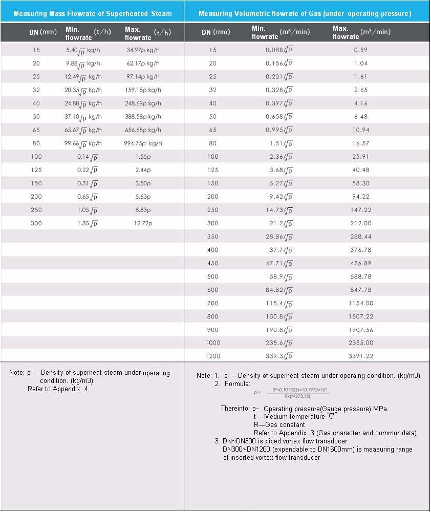
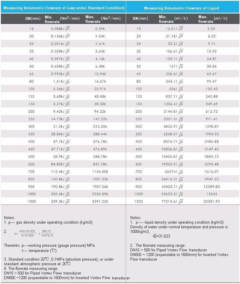
10 2. Selection of Vortex Flow Transducer DN Selection of measuring saturated steam mass flowrate Measuring range (t/h) (Note: Pressure above is gauge pressure) 7

11 (Continued) (Note: Pressure above is gauge pressure) 8
12 9
13 10
14 Selection Table of KVFN Intelligent Vortex Flow Transducer 11
15 Process Parameters Needed for KVFN Intelligent Vortex Flow Transducer Selection (1) Fluid name (2) Outer & Inner diameter of pipeline(mm) (3) State of measured media: Liquid, Gas, Steam (4) Scale flowrate unit (kg/ h, t/h, m 3 / h, Nm 3 / h) a) Under operating condition b) Under standard condition (5) Normal flowrate (6) Min flowrate, Max flowrate (specify the state of flowrate for gas medium) a) Under operating condition b) Under standard condition (7) Operating pressure (MPa) a) Absolute pressure b) Gauge pressure (8) Fluid temperature( ) : Max, Min, Normal (9) Fluid density (kg/ m 3 ) (specify the state of flowrate for gas medium) a) Operating Status b) Standard Status (10) Viscosity (Pa. s) (11) Gas component Volume percentage (for more than two kinds of mixed gas) (12) Explosion proof a) Intrinsical safe b) Flame proof (13) Pipe flange a) According to standard, code is for flange standard b) Flange drawing provided by customers (14) Output signal 4~20mA DC, pulse output, RS-485, Hart, ModBus (15) Power supply 24V DC, 3.6V lithium battery, 24V DC 3.6V lithium battery double power supply Notice: (1)~(8), (11)~ (15) must be provided for water & steam measurement. (1)~ (15) are provided for common gas (1) (2), (4) ~(10), (12)~(15) are provided for common solution & light oil. Please provide detailed value for parameters. Range value does not work. 12
16 Precaution of Handle & Transportation In order not to be damaged, do not open the package before meter received by customer. Handle with care during the transportation, do not crash, drench, impact and vibrate. Precaution of Storage Flow transducer should be installed in time once it arrives at the using place to avoid insulativity of amplifier reducing and metal parts being corroded etc. Pay special attention to follow things: (1) Try not to open the package to store in any condition; (2) Storage place should be: a. Damp proof and rain-proof b. Little mechanical vibration c. Temperature between -35~60, ideal temperature is about 25. (3) Should clean meter body totally before store used vortex flow transducer. (4) The flow transducer performance will be affected if long time outdoor storage. Therefor, please install it immediately once it is carried to the installing site. 13
17 Precaution of Installing Location Selection Although we have considered bad working condition during design, in order to ensure good performance and stability, should pay attention to the follow things when select installing location: (1) Ambient temperature Avoid installing the location with large temperature change. If the meter will be affected by heat radiation, please take measures of heat insulation and ventilation. (2) Ambient air Avoid installing flow transducer at the ambient with strong corrosive gas. If must be installed in corrosive ambient, should take measures of ventilation. (3) Mechanical vibration and impact Although flow transducer has tough structure, still should install flow transducer at location avoiding mechanical vibration and impact from measuring principle. If must install location with big vibration, should install pipe bracket to buffer. (4) Adjustable valve Adjustable valve should be installed downstream 5D away from transducer. If must be installed at upstream, straight pipe for upstream of transducer should be no less than 50D. (5) Water hammer When measure steam flow on horizontal pipe, location of flow transducer must not be on low point of pipe, because this is the location where condensate liquid deposited and cause water hammer easily. For discontinuous delivering gas pipe, water hammer will happen much easier when open-close which will affect flow transducer normal measuring, what s worse, it will damage the probe. Flow transducer should be installed in high point of pipe and install steam trap at low point of front pipe. (6) Others There should be enough space aound vortex flow transducer to: a. Regular maintenance, meter reading b. Wiring, pipe installation 14
18 Precaution of Installation & Application Vortex flow transducer must be used under certain condition. Please confirm whether the transducer is suitable to the operating condition (flowrate, pressure, temperature, explosion proof etc.) or not before installation. After open the package, please install as soon as possible to avoid being corroded by corrosive material or damped by raining. When store used transducer, must clean inside and outside of transducer completely. Avoid transducer being installed in place where temperature changes greatly or heat radiation occurs. If it is necessary, take measures of heat insulation or ventilation. Avoid transducer being installed in place where corrosive atmospheres surrounding. If it is necessary, take some measures of prevention of corrosion. Avoid transducer being installed in place with strong mechanical vibration and impact. If it is necessary to install on pipe with strong vibration, it needs to fasten pipe around transducer. When transducer is installed on the pipe, should not use meter body as lift point to lift meter and pipeline. Straight pipe at up & down stream should be as manual requirement, or it will affect measuring accuracy of transducer, what s worse, will damage transducer. 15
19 Flowing direction must be conformed with the arrow on the transducer. During flange or pipe welding, transducer should not be on the pipe to avoid damaging electronic parts. Avoid transducer installed on long overhead pipe, otherwise leakage will happen between transducer and flange caused by transducer drooping. If can not avoid, fitting device for pipe must be used. Transducer can be installed on vertical or horizontal pipe. For vertical pipe installation, flow direction should be down to up when measure liquid. Avoid transducer installed around valve exit, or open-close of valve will affect the measuring accuracy and meter service life, even damage transducer. For convenient maintenance, should install bypass pipe, especially fluid in pipeline can not be shut down during production. When clean pipeline, cleaning fluid should pass by-pass pipe to avoid damaging meter; if no by-pass line, a duct should be installed temporarily to replace meter. 16
20 Meter had better be installed indoors; if outdoor installation is necessary, should take measures of moisture proof and sun proof. There should be enough space around transducer installed to ensure convenient, wiring and regular maintenance. Specified shielded cable should be used as signal cable and shielding layer should be fastened to metal housing of transducer. Signal cable should not be parallel to power cable, the distance between them should be over 15cm. Place them into independent steel tube would be better. Fix cable and can not be shaken. Installing location of transducer should be far away from electrical noise, such as large power transformer, electromotor, welding machine and strong power supply etc. Radio interference should not be around installing location, otherwise, radio interference will affect normal operation of transducer. When open shutoff valve at up & down stream of transducer, it should be very slowly, and opening time should be no less than 2min. 17
21 Pressure of installing pipe should not exceed maximum rated pressure of transducer. When transducer parts are pressed, can not tighten or loosen fastening screw of probe and installing bolts of flange. Straight Pipe Requirement There are various structure of Vortex Flowmeter, installing & maintenance person should know very well of meter structure, features and flow signal conversion and install according to manual to ensure meter measuring accuracy. 1. Selection proper installation location and ambient Avoid equipment with strong power electrical, high frequency and strong power switch; avoid affected by high heat resources and radiation; avoid location with strong vibration and corrosive ambient etc, meanwhile, consider of convenient maintenance. To ensure fluid section not being affected, vortex flow transducer should be installed downstream any location that can cause fluid disturbing (such as diverging pipe, converging pipe and valve). The longest straight pipe should be used between flow resistance part and flowmeter. If there are two or more flow resistance parts at upstream of flowmeter, the straight pipe should be much longer. 2. Ensure enough straight pipes at upper & down stream The length of straight pipe 15D for upstream and 5D for downstream if converging pipe >15 is used in upstream of transducer installing site (shown as Fig. 1). The length of straight pipe 18D for upstream and 5D for downstream if diverging pipe>15 is used in upstream of transducer installing site (shown as Fig. 2). The length of straight pipe 20D for upstream and 5D for downstream if 90 elbow or T joint is used in upstream of transducer installing site(shown as Fig. 3). The length of straight pipe 25D for upstream and 5D for downstream if two 90 elbows on same plane in 18
22 upstream(shown as Fig. 4). The length of straight pipe 40D for upstream and 5D for downstream if two 90 elbows on different planes in upstream(shown as Fig. 5). Flow or pressure control valve should be installed at least 5D far away from the meter in downstream as possible, if these valves must be installed in the upstream, ensure 50D for upstream at least and 5D for downstream(shown as Fig. 6). 3. Companion pipe should be concentric to flowmeter, and coaxial offset should not be more than 0.05DN. The inside diameter of companion pipe for upstream and downstream should be the same as nominal diameter of flowmeter, and should meet requirements as below: 0.98DN D 1.05DN Thereinto: DN nominal diameter of the flowmeter D inside diameter of the companion pipe Sealing gasket between flange and transducer cannot be protruded into the pipe, and its ID can be slightly bigger than that of transducer. 4. Requirement for Pipe Vibration Avoid transducer being installed on the pipe with strong vibration, if you have to installed, vibration damping measures should be taken. Install fitting device at 2D far away from the flowmeter on both side of upstream & downstream and vibration pad should be used too. 19

23 Installation Type 1. It is the most common way to install transducer on horizontal pipe No matter what kinds of fluid, transducer can be installed on horizontal pipe, especially for overheated steam with enough heat insulating layer and liquid. If the process pipe heat insulating of saturated & overheated steam is not very good, please use it limitedly. (1) When measure gas or steam, transducer should be installed at the top of pipeline if the gas or steam contains few liquid. (2) When measure liquid, transducer should be installed at the bottom of pipeline if the liquid contains little gas. 2. Transducer installed on vertical pipe When used in gas, transducer could be installed on vertical pipe with no considering of flow direction, but for gas contains few liquid, the gas flow direction should be from down to up. When used in liquid, flow direction should be from down to up, avoid extra weight of the liquid to exert on the probe. 3. Lateral installation on horizontal pipe Transducer can be installed laterally on horizontal pipe for all fluids. Particularly for superheated steam, saturated steam and cryogenic liquids, if allowed, transducer should be installed laterally to avoid amplifier from being affected greatly by temperature. 20
24 4. Inverse installation on horizontal pipe It is not suggested to install transducer inversely for normal gas or superheated steam, but it is suitable to saturated steam, high temperature liquid or the situation that dirty pipe needs cleaning frequently. When install, take the following requirements for cable length and min. space as reference: (1) Min space of every direction is 100mm (2) Cable length L +150mm 21

25 How to Select Pressure and Temperature Measuring Point If you require measuring pressure or temperature near the flowmeter, pressure measuring point should be 3~5D at downstream of transducer and temperature measuring point should be 6~8D at downstream of transducer. Thereinto: (1) Condensing flex tube (2) Needle valve (3) Vortex transducer (4) Pressure transmitter (5) Conducting pressure socket (6) Pt100 ( temperature transmitter) (7) Socket of Pt100 (8) L shape duct 22
 is used as connecting wire.")

26 Wiring Wiring for output frequency signal This meter uses three wires to transmit frequency output signal to other external equipments, with power supply 24V ±10%, the minimum load resistor of output circuit 10kΩ, the maximum capacitance 0.22µF, and resistance of shielded wire must be less than 50Ω. Normally, a three cores shielded wire (RVVP3 0.5mm 2 ) is used as connecting wire. The shielding layer should be connected to the grounding screw in amplifier box reliably. Appropriate shielded wire should be used to meet field temperature when meter used in high or low temperature ambient. When the atmosphere surrounded the field contains oil, solvent or other corrosive gas and liquid, appropriate shielded wire should be used to meet this environment. Connecting wire should not be parallel to the power cable, with distance between them more than 15cm at least. Place them in independent steel tube would be better. Fix connecting wire and can not be shaken. Wiring for RS-485 Communication Four wires transmission is applied between vortex flowmeter with RS-485 output and other equipments. Power supply is 24V DC ±10%. Normally, 600V PVC insulated wire or cable should be used as connecting wire. The two cores shielded wire (RVVP2 0.5mm 2 ) should be used where electrical noise occurs likely. The shielding layer should be connected to the grounding screw in amplifier box reliably. Appropriate shielded wire should be used to meet field temperature when meter used in high or low temperature ambient. When the atmosphere surrounded the field contains oil, solvent or other corrosive gas and liquid, appropriate shielded wire should meet this environment. 23
. Normally, 600V PVC insulated wire or cable should be used as connecting wire.")

27 Wiring for meter with two-wire 4~20mA output signal This meter uses two-wire to transmit 4~20mA output signal to other equipments, with power supply 24V DC ±10%, the maximum load resistance for output circuit 600Ω(including resistance of cable). Normally, 600V PVC insulated wire or cable should be used as connecting wire. The two cores shielded wire (RVVP2 0.5mm 2 ) should be used where electrical noise occurs likely. The shielding layer should be connected to the grounding screw in amplifier box reliably. Appropriate shielded wire should be used to meet field temperature when meter used in high or low temperature ambient. Wiring for 4~20mA and frequency signal output at the same time 24

28 Wiring for transducer with temperature and pressure compensation 25

29 Outline Dimension( Wafer Type) Notes: 1. This outline drawing is high temperature type vortex flow transducer; standard type does not have cooling fin; 2. Flange dimension refers to GB/T , unit is mm. 26

30 Notes: 1. This outline drawing is high temperature vortex flow transducer; standard type does not have cooling fin; 2. Flange dimension refers to GB/T , unit is mm. 27

31 Outline Dimension (Flange Type) Notes: 1. This outline drawing is high temperature vortex flow transducer; standard type does not have cooling fin; 2. Flange dimension refers to GB/T , unit is mm. 28

 Note: Above information is just for")
32 Outline Dimension(Fixed Insertion Type) Parts: 1. Converter 2. Body flange 3. Short duct with flange 4. Outer wall of customer s pipe 5. Inserted rod 6. Vortex transducer 7. Customer s pipe 8. R=1/2 inner diameter of the pipe (DN<800) R=0.121 inner diameter of the pipe (DN 800) Note: Above information is just for reference, mm for unit. 32
33 Installation of Fixed Insertion Transducer Installation Procedures: 1. Drill a hole in the customer s pipe by method of torch cutting, with diameter slightly less than Φ100, no burr at the edges of the hole to make the measuring probe inserted through it freely. 2. Weld a matched short-duct (supplied by Kent) on the hole on the pipe by spot welding, the axes line of the short-duct is perpendicular 90º to the one of the pipe, as well as its extending line is through the circle center of cross-section of the pipe, then welding all-around. 3. Put gasket of the duct flange, insert probe into the short-duct, then mount bolts and check if it is even around the flange, and the flow direction is conformed. 4. Check all if it is good, open valve slowly and check the leakage (care of personnel safety). Caution: 1. Flow direction must be conformed with the flow arrow on the meter body; 2. When weld the flange and pipe, the transducer should not be installed on the pipe to avoid any damage of the transducer. 33
 R=0.")
34 Outline Dimension(Adjustable Insertion Type) Parts: 1. Converter 2. Screw rod 3. Encloser 4. Seat for inserted rod 5. Ball valve 6. Inserted rod 7. Vortex transducer 8. Vortex transducer 9. Hand handle 10. Guide rod 11. Scale 12. R=1/2 inner diameter of the pipe (DN<800) R=0.121 inner diameter of the pipe (DN 800) 34
35 Note: Above information is just for reference, mm for unit. Installation of Adjustable Insertion Transducer Installation Procedures: 1. Drill a hole in the customer's pipe by method of torch cutting, with diameter slightly less than Φ100, no burr at the edges of the hole to make the measuring probe inserted through it freely. 2. Weld a matched short-duct (supplied by Kent) on the hole on the pipe by spot welding, the axes line of the short-duct is perpendicular 90º to the one of the pipe, as well as its extending line is through the circle center of cross-section of the pipe, then welding all-around. 3. First install ball-valve (Q41F-16R-32R, ID 100mm, supplied by customer), then install transducer on the valve. 4. Calculate inserted deep R, measure the length of the short duct and ball valve, adjust screw rod to make the inserted deep is conformed with the specification. 5. Check all if it is good, open valve slowly and check the leakage (care of personnel safety). Caution: 1. Flow direction must be conformed with the flow arrow on the meter body; 2. When weld the flange and pipe, the transducer should not be installed on the pipe to avoid any damage of the transducer. Application Precaution for Explosion Proof Vortex Flow Transducer Divide category of hazardous area correctly; Select and install proper explosion proof vortex meter; maintain and repair in time and correctly. Division of hazardous area, selection, installation and maintenance and so on must be conformed to safety standard system such as GB , GB , and GB etc. Make sure that selection is conformed to design (including vortex meter model and specification, power grade, protection grade, installation type, explosion proof mark, cable, thread etc.) Confirm installing site and leave sufficient space and path around meter. Following factors should be considered: convenient usage, operation, running, repair& maintenance, disposal of urgent matters (urgent power off) etc. Avoid disadvantage factors such as stream, raining, thunder, moisture, thermal radiation, high temperature object, 35
36 vibration etc. Grounding is one of the most important precautions in meter electrical technology. This connection is to transfer the static charge (static charge generated during fluid transmission, electromagnetic induction, electrostatic induction etc.) to ground. Application Precaution for Flameproof Vortex Flow Transducer This flameproof flowmeter is approved by National Supervision and Inspection Center for Explosion Protection and Safety of Instrumentation (NEPSI), according to National Standard GB3896.1/4-2000, mark of flameproof is Exd IIBT3~6. 1. Avoid opening wiring box and inlet wire box of flameproof vortex flowmeter for daily maintenance. Cut off power before open. If open the flameproof housing, flameproof surface should be protected with no damage. Put flameproof surface upwards and can not touch the earth directly when check. 2. Non-flameproof meter and lamp fixture etc. are not allowed for maintenance on site. All tools should be flameproof. 3. Grounding terminal is available on housing. Meter should be grounded reliably while operation. Application Precaution for Intrinsical Safe Vortex Flow Transducer This intrinsical safe meter is approved by National Supervision and Inspection Center for Explosion Protection and Safety of Instrumentation (NEPSI), according to National Standard GB3896.1/4-2000, mark of explosion proof is ExibIICT3~6. It combined with safety barrier to make up an intrinsical safe explosion proof system, which can be used in relevant hazardous areas. You need to care of follows before installation: 1. There is grounding terminal in meter housing, you must ground the meter reliably; 2. This intrinsical safe meter must be combined with safety barrier which must be approved by Organization of Explosion Proof Inspection to make up intrinsical safe system; 3. The three cores shielded cable (core cross section is 0.5mm 2, with insulating sheath ) be used for connecting between meter to safety barrier, the shielded layer be single-end grounded in non-hazardous area. Cable layout should eliminate the electromagnetic interference as possible and make the cable distribution capacitance within 0.05F; 4. Ambient temperature range: 25 ~ +60. The relationship between temperature levels of explosion proof mark and inflame temperature as below: Temperature Level T1 T2 T3 T4 T5 T6 Inflame Temperature 450<t 300<t <t <t <t <t The safety barrier should be installed in non-hazardous areas and operation should be according to the operation instruction; 6. Customer should not change the electric elements by himself; 7. Must obey the regulations of National Standard GB while installation and maintenance. 36
37 Configuration of Intrinsical Safe System Safety barrier is zener or insulated type; please connect vortex flowmeter, flow calculator and safety barrier according to safety barrier instruction. Appendix. 1 Measuring Principle of Vortex Flow Transducer Working Principle When a column body placed in flowing fluids in pipe, a series of vortices will be generated alternately on each side of the object as shown as below, these eddies known as Karman Vortices, the frequency of the vortex shedding is related to the velocity of the fluid and the width of the body. Expressed by formula as below: f=sr.v/d Thereinto f----frequency of Karman Vortex shedding Sr----Strouhal number v----velocity d----width of column object Because the frequency of the vortex shedding is proportional to the velocity, it can be used to calculate the instantaneous flowrate. Strouhal number is a very important coefficient in the Vortex Flowmeter. In the range of straight line of St 0.17 in curve, frequency of vortex shedding is proportional to the velocity, so as long as the frequency (f) be detected, the velocity (v) will be obtained, and volumetric flowrate will be got according to v. For KVFN Vortex Flowmeter, its frequency of the vortex shedding was detected by the stress force which exerted 37
38 on the sensor (probe) using the piezoelectric unit which is built in sensor. Appendix. 2 Amplifier Circuit Circuit Diagram 1. Electric charge converter 2. Amplifier 3. Lowpass filter 4. Smith trigger 5. Stabilized voltage supply 6. Output amplifier 7. Power supply 1. Electric charge converter 2. Amplifier 3. Low-pass filter 4. Smith trigger 5. F/V converter 6. Stabilized voltage supply 7. V/I converter 8. Power supply 9. Load resistor Electric charge converter Convert the alternating charge from piezoelectric unit into voltage, which is proportional to quantity of the charge. Alternating amplifier and low-pass filter Amplify signal and eliminate noise. When the velocity is low, high frequency noise produced from pipe vibration may be superposed on the output wave of charge converter to form a superposed wave. When high velocity, differential pulsed signal forms a wave involved low frequency swing. At low velocity (small output voltage), high 38
39 frequency noise be eliminated by lowpass filter, and at high velocity (large output voltage), along with the lowpass feature be released and its feature of amplitude limit to appear, to prevent the signal from amplifying low frequency noise. Smith trigger Convert the detected voltage of the vortices frequency into pulse signal with a range of amplitude. Due to circuit of Smith trigger has a hysteretic function to input and output signal, therefore it can prevent oscillating caused by noises. F/V converter Convert pulse signal from Smith trigger output into analog vlotage that is proportional to frequency. V/I converter Convert analog output voltage into 4~20mA DC. Pulse output amplifier Amplify pulse frequency signal from Smith trigger. 39

40 Appendix. 3 Gas Character & Essential Data 40

41 Appendix. 4 Density of Overheated Steam( 1) (unit: kg/m 3 ) 41

42 Appendix. 4 Density of Overheated Steam( 2) (unit: kg/m 3 ) 42

43 43

44 Appendix. 5 Density of Saturated Steam (unit: kg/m 3 ) 44
; temperature t ( ) 45")
45 Saturated steam density table: density ρ(kg/m3); Absolute pressure P ( MPa); temperature t ( ) 45
46 SHANGHAI KENT INTELLIGENCE METER CO., LTD. Add: 5553 Hutai Rd., Shanghai , China Tel: Fax: Http: //
CATALOG KVFN. Vortex Flowmeter
 CATALOG KVFN Vortex Flowmeter Main Features of KVFN Intelligent Vortex Flow Transducer Best of KVFN Intelligent Vortex Flow Transducer is piezocrystal built in bluff body to avoid fluid turbulence caused
CATALOG KTLU. Vortex Flowmeter
 CATALOG KTLU Vortex Flowmeter Technical Features No moving parts, high reliability and durability Convenient installation and maintenance Sensor not contact with the measured fluids directly, stable performance
Satellite photo of cloud vortices caused by a mountain (Courtesy of our friends at NASA) tekvorx Operation Showing Simplified Construction
 tekvorx Operation Showing Simplified Construction") Sensing the pulse of industry tekvorx TV01 Multivariable Vortex flow Sensors Vortex flow sensors derive their name from a natural phenomenon of fluid dynamics. When a gas or relatively low viscosity liquid
Sensing the pulse of industry tekvorx TV01 Multivariable Vortex flow Sensors Vortex flow sensors derive their name from a natural phenomenon of fluid dynamics. When a gas or relatively low viscosity liquid
DY-LWGY Liquid turbine flow meter
 Typical Application: liquid with no impurities and no corrosion, such as water, diesel, methanol. DY-LWGY Liquid turbine flow meter One. Overview DY-LWGY series Turbine Flow has its simple structure, light
Instruction Manual. DMF-1-Series Coriolis Mass Flow Meter
 1 京制 01050054 号 Instruction Manual DMF-1-Series Coriolis Mass Flow Meter Beijing Sincerity Automatic Equipment Co., LTD Tel: +86(010)52073959/ 52073956 18600270515 2 NOTICE We thank you very much for your
Vortex Flowmeters VFM 3100 F-T VFM 3100 W-T
 KROHNE 10/2001 7.02313.23.00 GR/OP Vortex Flowmeters F-T W-T Variable area flowmeters Vortex flowmeters Flow controllers Electromagnetic flowmeters Ultrasonic flowmeters Mass flowmeters Level measuring
Series 8000 Vortex Flow Meter
 VFM Series 8000 Vortex Flow Meter Operating Principle The operation of the VFM 8000 is based on the Karman Vortex Street. Vortices are formed as the fluid flows around the shedder body which are alternately
F-2600 SERIES INLINE VORTEX FLOW METER
 F-2600 SERIES INLINE VORTEX FLOW METER APPLICATIONS Saturated steam Hot water to 500 F (260 C) standard 750 F (400 C) optional Applications with optional pressure sensor Superheated steam to 500 F (260
KTLDE Intelligent Electromagnetic Flowmeter
 KTLDE Intelligent Electromagnetic Flowmeter Contents 1 The general features of KTLDE intelligent electromagnetic flowmeter 2 Main features of KTLDE intelligent electromagnetic flowmeter 3 Technical parameter
S TL U VCF V-cone Flow Transducer
 S TL U VCF V-cone Flow Transducer Contents 1 General features of STL U VCF V-cone flow transducer 3 Main features of STL U VCF V-cone flow transducer 6 Technical parameter table of STL U VCF V-cone flow
VFM4070C SWIRLMAX. Vortex Flowmeter OUTLINE FEATURES OPERATING PRINCIPLE STANDARED SPECIFICATION. General Specification. Sensor Specification
 SWIRMAX VFM4070C Vortex Flowmeter OUTINE SWIRMAX is 2-wire, all-in-one type vortex flowmeter with both temperature and pressure sensors integrally mounted into the housing. It allows temperature and pressure
Model TUR-200D Turbine Flowmeter
 General Specifications Model TUR-200D Turbine Flowmeter Liquid flows through the turbine housing causing an internal rotor to spin. As the rotor spins, an electrical signal is generated in the pickup coil.
Fundamental Training. Flow Con t
 Fundamental Training Flow Con t 1 Contents Topics: Slide No: Velocity flow meters 3-11 Mass flow meters 12-17 Displacement meters 18 Exercise 19-20 2 Velocity Meter Magnetic Flowmeter Faraday s Law of
Vortex Eggs Delta Flowmeter
 Product Data Sheet PDS-FLM Vortex Eggs Delta Flowmeter Technical Specifications (Liquid, Gas & Air) Easy to read Free positioning EEPROM DESCRIPTION The unique sensor body and transmitter design makes
F-2500 SERIES VORTEX METER
 F-500 SERIES VORTEX METER APPLICATIONS Saturated steam Hot water to F (0 C) Applications with optional pressure sensor Superheated steam to F (0 C) Compressed air Industrial gases CALIBRATION Each meter
OPTISWIRL 4070 Technical Datasheet
 OPTISWIRL 4070 Technical Datasheet Vortex flowmeter Integrated pressure and temperature compensation Temperature compensation for saturated steam included as standard All OPTISWIRL versions in 2-wire technology
Digital Vortex Flowmeter. digitalyewflo. Digital Vortex Flowmeter. Series
 Digital Vortex meter digitalyewflo Digital Vortex meter Series Unrivaled Performance, Functionality and Ease of Use Series Standard Type / Multi-variable Type High Temperature / Cryogenic Type Reduced
VORTEX FLOW METTER DVH. Despriction. Advantages of the DVH Vortex Flow Meter
 R VORTEX FLOW METTER DVH Measuring range: 3-8... 3 057-280 187 m3n/h Accuray: ± 0,7 % of reading (liquids) ± 1 % of reading (gases and steam) P m a x : 100 bar abs; tm ax : 400 C Connection: ANSI ½ up
Flange connection type vortex flowmeter. Flang card type vortex flowmeter. Temperature-pressure compensation type. Insertion type vortex flowmeter
 Kaifeng Qingtianweiye Flow Instrument Co.,Ltd No. 1, Wangbai Road, Huanglong Industrial one, Kaifeng, Henan, China (Mainland) Tel :+86-378-7880299 Fax:+86-378-6669963 http://www.hnqtyb.cn/ Exectromagetic
Model 1000 Vortex Meter
 Model 1000 Vortex Meter Installation and Instruction Manual Table of Contents General Information... 1 1-1 General... 1 1-2 Principles of Operation... 1 1-3 Sensor Operation... 1 1-4 Calibration Factor...
Liquid Turbine Flow Meter OwnerÊs Manual
 Liquid Turbine Flow Meter OwnerÊs Manual Manual LWGY-G Rev.1.0 Content 1.0 GENERAL INFORMATION... 1 2.0 SPECIFICATIONS... 2 3.0 OPERATION CONDITIONS... 3 4.0 CAUTIONS FOR INSTALLATION... 4 5.0 DIMENSION...
OPTISWIRL 4070 Technical Datasheet
 OPTISWIRL 4070 Technical Datasheet Vortex flowmeter Integrated pressure and temperature compensation Temperature compensation for saturated steam included as standard All OPTISWIRL versions in 2-wire technology
F-2600 SERIES INLINE VORTEX FLOW METER
 F-2600 SERIES ININE VORTEX FOW METER APPICATIONS Saturated steam Hot water to 500 F (260 C) standard 750 F (400 C) optional Applications with optional pressure sensor Superheated steam to 500 F (260 C)
F-2700 SERIES INSERTION VORTEX FLOW METER
 F-2700 SERIES INSERTION VORTEX FLOW METER APPLICATIONS Saturated steam Hot water to 500 F (260 C) standard 750 F (400 C) optional Applications with optional pressure sensor Superheated steam to 500 F (260
VersaFlow Vortex 100 Vortex Flow Meter Specifications
 VersaFlow Vortex 100 Vortex Flow Meter Specifications 34-VF-03-05 May 2011 The All-In-One Solution The VERSAFLOW is the only vortex flowmeter with integrated and temperature compensation in 2- wire technology.
F-2700 SERIES INSERTION VORTEX FLOW METER
 F-2700 SERIES INSERTION VORTEX FLOW METER CALIBRATION Every ONICON flow meter is wet calibrated in a flow laboratory against standards that are directly traceable to N.I.S.T. A certificate of calibration
Armstrong In-Line and Insertion Vortex Flow Meters
 Armstrong In-Line and Insertion Vortex Flow Meters Designs, materials, weights and performance ratings are approximate and subject to change without notice. Visit for up-to-date information. 1 In-Line
Vortex Flowmeter FV4000 (TRIO-WIRL V) Swirl Flowmeter FS4000 (TRIO-WIRL S) For flow rate and volume measurement of liquids, gases and steam
 Swirl Flowmeter FS4000 (TRIO-WIRL S) For flow rate and volume measurement of liquids, gases and steam") Vortex Flowmeter FV4000 (TRIO-WIRL V) Swirl Flowmeter FS4000 (TRIO-WIRL S) For flow rate and volume measurement of liquids, gases and steam Cost savings due to high accuracy Low investment cost through
Vortex Flowmeter FV4000 (TRIO-WIRL V) Swirl Flowmeter FS4000 (TRIO-WIRL S) For flow rate and volume measurement of liquids, gases and steam Cost savings due to high accuracy Low investment cost through
Multivariable Vortex Flow Meter
 Multivariable Vortex Flow Meter DVH Sensor Design w/o sealing Fully welded sensor Integrated temperature and pressure measurement (optional) Calculation of mass and density possible High temperature version
VORTEX IN-LINE FLOW METERS
 VORTEX IN-LINE FLOW METERS Principles of Operation Vortices are created when a fluid passes around a bluff body as shown below. Vortices are alternately shed on each side of the body, degrees out of phase
RUN ACCUM. TOTAL STOP BAT LOW HIGH
 TURBOPULSE TURBINE FLOWMETER INSTRUCTION MANUAL gal RUN ACCUM. TOTAL STOP BAT LOW HIGH RESET > PROGRAM ENTER ACCUM TOTAL ^ RATE TOTAL TP050 TABLE OF CONTENTS 1. INTRODUCTION Overview 1 1.1 Model number
Multivariable Vortex Flow Meter
 Multivariable Vortex Flow Meter DVH Sensor Design w/o sealing Fully welded sensor Integrated temperature and pressure measurement (optional) Calculation of mass and density possible High temperature version
Transmitters. Differential Pressure Transmitters Pneumatic Design FOXBORO 13A D/P Cell
 Transmitters Differential Pressure Transmitters Pneumatic Design FOXBORO 13A D/P Cell Oldest design, developed during WW 2. Can be used for flow, level, and pressure, vent low side. Several ranges 0 to
SITRANS FX300 4/289. System Overview. Overview
 Siemens G 2008 SITRNS F flowmeters Overview System Overview Version Single transmitter Dual transmitter Options Standard Pressure sensor Flange Pressure sensor and isola- Standard tion valve Sandwich vortex
PFA Eddysonic flowmeter
 PFA Eddysonic flowmeter CE marking Approval Conforms to the CE marking The Eddysonic Flowmeter is a flowmeter for fluids that detects the vortex street using the ultrasonic sensor mounted on the outside
Exercise 4-1. Flowmeters EXERCISE OBJECTIVE DISCUSSION OUTLINE DISCUSSION. Rotameters. How do rotameter tubes work?
 Exercise 4-1 Flowmeters EXERCISE OBJECTIVE Learn the basics of differential pressure flowmeters via the use of a Venturi tube and learn how to safely connect (and disconnect) a differential pressure flowmeter
Vortex Flow Meter Model DVH
 Vortex Flow Meter measuring monitoring analysing DVH Measuring range: 3-8... 3057-280187 Nm³/h Accuracy: ± 0,7 % of reading (liquids) ± 1 % of reading (gases and steam) p max : 100 bar abs; t max : 400
4-20mA, pulse with HART or pulse with RS485 are selectable. No moving parts, no abrasion, non-wearing parts inside, fully welded SS304
 VORTEX FLOW METER Vortex Flowmeter Advantages: Integrated pressure and temperature compensation. 4-20mA, pulse with HART or pulse with RS485 are selectable. Wide temperature range up to highest temperature
Pro-V Multivariable Flowmeter Model M24 In-line Vortex
 Pro-V Multivariable Flowmeter Model M24 In-line Vortex Pro-V TM Advantage: VorTek Instruments Pro-V multivariable flowmeters utilize three primary sensing elements a vortex shedding velocity sensor, an
Hot Tap Insertion Vortex
 Hot Tap Insertion Vortex Product Features The same insertion meter can measure Steam, Gases or Liquids. Standardize on an insertion bar that can measure line sizes 2 48 Heavy Duty & Maintenance Free Design
Vortex In Line Flow Meter
 Vortex In Line Flow Meter Principles of Operation Vortices are created when a fluid passes around a bluff body as shown below. Vortices are alternately shed on each side of the body, 0 degrees out of phase
VersaFlow Vortex 100 Vortex Flow Meter Specifications
 VersaFlow Vortex 100 Vortex Flow Meter Specifications 34-VF-03-05 May 2011 The All-In-One Solution The VERSAFLOW is the only vortex flowmeter with integrated pressure and temperature compensation in 2-
LBTC Series Positive Displacement Rotary Vane Flow Meters
 LBTC Series Positive Displacement Rotary Vane Flow Meters Summary LBTC Series positive displacement rotary vane flow meters are independently designed and manufactured by our company on the base of absorbing
Flange connection type vortex flowmeter. Flange card type vortex flowmeter. Temperature-pressure compensation type. Insertion type vortex flowmeter
 Exectromagetic flowmeter Tu bin f o m U a onic f o m Th o ing d vic Ro am LUGB-2 Flange connection type vortex flowmeter Flange card type vortex flowmeter Temperature-pressure compensation type Insertion
VorTek Series M22 and M23 Pro-V Multi-Parameter Vortex Loop Powered Mass Flow Meters. Instruction Manual
 Series M22/M23 Instruction Manual Table of Contents VorTek Series M22 and M23 Pro-V Multi-Parameter Vortex Loop Powered Mass Flow Meters Models M22-VT, M22-VTP, M23-VT, M23-VTP Instruction Manual Document
DVH. Vortex Flowmeter. Measuring range: Nm³/h. Accuracy: ± 0,7% of reading (liquids) ± 1% of reading (gases and steam) p max
 ± 1% of reading (gases and steam) p max") Vortex Flowmeter measuring monitoring analysing DVH Measuring range: 3-8... 3057-280187 Nm³/h Accuracy: ± 0,7% of reading (liquids) ± 1% of reading (gases and steam) p max : 100 bar abs; t max : 400 C
Vortex Flowmeter measuring monitoring analysing DVH Measuring range: 3-8... 3057-280187 Nm³/h Accuracy: ± 0,7% of reading (liquids) ± 1% of reading (gases and steam) p max : 100 bar abs; t max : 400 C
The readings you need, right where you need them. AX Series Vortex Meters
 The readings you need, right where you need them. AX Series Vortex Meters Multivariable function from a single meter Vortex multivariable meters from Azbil North America employ three sensing elements in
Gauges, Sight Glasses and Vacuum Breakers
 Gauges, Sight Glasses and Vacuum Breakers Gauges, Sight Glasses and Vacuum Breakers Gauges Pressure gauges Pressure gauges should be installed in at least the following situations: Upstream of a pressure
F-2600 & F-2700 Series Vortex Flow Meter Installation and Operation Guide
 FLOW AND ENERGY MEASUREMENT F-2600 & F-2700 Series Vortex Flow Meter Installation and Operation Guide 11451 Belcher Road South, Largo, FL 33773 USA Tel +1 (727) 447-6140 Fax +1 (727) 442-5699 www.onicon.com
VIM20 Vortex Insertion Flowmeter
 Local regulations may restrict the use of this product to below the conditions quoted. In the interests of development and improvement of the product, we reserve the right to change the specification without
Differential Pressure Transmitter
 Specifications/Instructions Differential Pressure Transmitter General Model PY9000D is a differential pressure transmitter that uses a ceramic cantilever sensor. Deflection of the ceramic cantilever caused
VIM20 Vortex Insertion Flowmeter
 Local regulations may restrict the use of this product to below the conditions quoted. In the interests of development and improvement of the product, we reserve the right to change the specification without
GE Sensing. PanaFlow MV. Vortex Flowmeter. User s Manual
 GE Sensing PanaFlow MV Vortex Flowmeter User s Manual GE Sensing Panaflow MV Vortex Flowmeter User s Manual 910-279A June 2007 Warranty Each instrument manufactured by GE Sensing, Inc. is warranted to
Model 5000 Vortex Meter
 Model 5000 Vortex Meter Installation and Instruction Manual Table of Contents General Information... 1 1-1 General... 1 1-2 Principles of Operation... 1 1-3 Sensor Operation... 1 1-4 Calibration Factor...
VIM20 Vortex Insertion Flowmeter
 VIM20 Principle of Operation Vortex flowmeters measure flows of liquid, gas and steam by detecting the frequency at which vortices are alternately shed from a bluff body. According to proven laws of physics,
Vortex Flowmeter Model DVE
 Vortex Flowmeter Multi-Parameter measuring monitoring analysing DVE Measuring range Liquids: 5.2-157... 284-85371 m³/h Air: 89-1463... 26915-2467081 Nm 3 /h (20 C, 0 bar rel) Saturated steam: 81-938...
Thermal Gas Mass Flowmeter Series TMF-300
 Thermal Gas Mass Flowmeter Series TMF-300 Technical Superiorities a true mass flow meter which could measure the gas flow conveniently and accurately without compensation for temperature or pressure. Mass
MULTICHANNEL ULTRASONIC FLOW METER AFLOWT UF
 MULTICHANNEL ULTRASONIC FLOW METER AFLOWT UF VERSION UF-5xx d INSTALLATION MANUAL ISO 9001:2008 CONTENTS Page INTRODUCTION... 3 1. SAFETY INSTRUCTIONS... 4 2. MOUNTING PREPARATION... 4 3. MOUNTING REQUIREMENTS...
Vortex In Line Flow Meter
 Principles of Operation Vortices are created when a fluid passes around a bluff body as shown below. Vortices are alternately shed on each side of the body, 0 degrees out of phase to each other, resulting
Sierra Series 240 and 241 Innova-Mass Multi-Parameter Vortex Mass Flow Meters. Instruction Manual
 Series 24-HP Instruction Manual Table of Contents Sierra Series 240 and 241 Innova-Mass Multi-Parameter Vortex Mass Flow Meters Models 240-VT, 240-VTP, 241-VT, 241-VTP Instruction Manual Part Number: IM-24-HP,
Digital Vortex Flowmeter. digitalyewflo. Digital Vortex Flowmeter. Series. Bulletin 01F06A02-00E.
 Digital Vortex meter digitalyewflo Digital Vortex meter Series Bulletin 01F06A02-00E www.yokogawa.com/ Series Simple body construction for easy installation and high level of safety 2 3 Standard Type /
Air Flow Measurement Technologies
 Page 1/7 Typical Air Flow Measurement Applications Air Flow Control True Flow Feedback Theory of Vortex Shedding Air Flow Measurement Pitot Air Flow Measurement Thermal Air Flow Measurement Advantages
F-1500 SERIES INSERTION TURBINE FLOW METER FEATURES Belcher Road South, Largo, FL USA Tel +1 (727) Fax +1 (727)
 Fax +1 (727)") F-1500 SERIES INSERTION TURBINE FLOW METER Insertion turbine flow meters are ideal for use in larger steam lines where downsizing the line size to improve flow measurement is not desirable. In these applications,
F-1500 SERIES INSERTION TURBINE FLOW METER Insertion turbine flow meters are ideal for use in larger steam lines where downsizing the line size to improve flow measurement is not desirable. In these applications,
F-1500 SERIES INSERTION TURBINE FLOW METER
 F-1500 SERIES INSERTION TURBINE FLOW METER APPLICATIONS Saturated steam Hot water to 450 F (232 C) standard 850 F (454 C) optional Applications with optional pressure sensor Superheated steam to 450 F
PanaFlow MV80. In-line Multivariable Flowmeter for Mass, Temperature, and Pressure. GE Sensing. Applications. Key Benefits
 Key Benefits Multivariable vortex flowmeter for measuring volumetric flow, temperature, pressure, density, and mass flow using a single meter Measures most gases, liquids and steam without the need to
Hydro-Flow Model 2200 Fixed Insertion Vortex Flowmeter Installation and Operation Manual
 Hydro-Flow Model 00 Fixed Insertion Vortex Flowmeter Installation and Operation Manual Table of Contents Model and Suffix Codes. Theory and Identification.. Installation Guidelines 4 Mechanical Drawing:
The readings you need, right where you need them. AX Series Vortex Meters
 The readings you need, right where you need them. AX Series Vortex Meters Multivariable function from a single meter Principles of Operation Vortex multivariable meters from Azbil North America employ
Rosemount 485 Annubar Pak-Lok Assembly
 Quick Installation Guide 00825-0300-809, Rev EA Pak-Lok 85 Annubar Rosemount 85 Annubar Pak-Lok Assembly Start Step 1: Location and Orientation Step 2: Drill Holes into Pipe Step 3: Weld Mounting Hardware
VLM20 In-line Vortex Flowmeter
 ocal regulations may restrict the use of this product to below the conditions quoted. In the interests of development and improvement of the product, we reserve the right to change the specification without
F-4600 INLINE ULTRASONIC FLOW METER Installation and Operation Guide
 F-4600 INLINE ULTRASONIC FLOW METER Installation and Operation Guide 11451 Belcher Road South, Largo, FL 33773 USA Tel +1 (727) 447-6140 Fax +1 (727) 442-5699 1054-7 / 34405 www.onicon.com sales@onicon.com
Pressure Transmitter
 Specifications/Instructions Pressure Transmitter General Model PY7100A pressure transmitter is a small pressure transmitter using a semiconductor strain gauge. It detects the pressure of chilled/hot water,
STEEMCO-MAS Flowmeter for Steam
 STEEMCO-MAS Flowmeter for Steam Typical Applications The STEEMCO-MAS flow meters measure the mass flow of superheated steam within the process industries, including chemical, petro-chemical, pharmaceutical
Intrinsically safe presure transmitters for hazardous environments Type MBS 4201, MBS 4251, MBS 4701 and MBS Technical brochure
 Intrinsically safe presure transmitters for hazardous environments Type MBS 4201, MBS 4251, MBS 4701 and MBS 4751 Technical brochure Features Ex ll 1G EEx ia llc T4 - T6 in compliance with ATEX 100a Applicable
To avoid injury, death of personnel ordamage to instrument, the operator must refer to an explanation in the User smanual.
 www.malema.com VF-3000 Flow Sensor M-1500 INSTRUCTION MANUAL Non-invasive Inline 1. NOTICE 1) This manual should be passed on to the installer and the operator of this product. 2) Please read this manual
Hydro-Flow Model 2300 Installation and Operation Guide B
 Hydro-Flow Model 2300 Installation and Operation Guide 5700508-B Contents: Understanding and Identifying Your Flow Meter 1 Installing Your Flow Meter 3 Electrical Connections.. 7 Mechanical and Electrical
TEK-F LUX 1400A. Electromagnetic Flowmeter. Flow Level Temperature Pressure Valves Analyzers Accessories TekValSys FLOW
 Technology Solutions TEK-F LUX 1400A Electromagnetic Flowmeter FLOW www.tek-trol.com Flow Level Temperature Pressure Valves Analyzers Accessories TekValSys Introduction Electromagnetic flowmeters are also
DVH / DVE. Vortex Flow Meter. Instruction Manual. Page 1 of 102
 Vortex Flow Meter DVH / DVE Instruction Manual Page 1 of 102 Contents 1 IDENTIFICATION... 5 1.1 Supplier / Manufacturer... 5 1.2 Producttype... 5 1.3 Issue date... 5 1.4 Version No.... 5 1.5 Tagging /
UL6300 SONICMAX. Ultrasonic Clamp-on Flowmeter OUTLINE FEATURES STANDARD SPECIFICATION. Common specification
 SONICMAX UL63 Ultrasonic Clamp-on Flowmeter OUTLINE SONICMAX UL63 is the ultrasonic flowmeter of the time flight system which combined the highly efficient converter (UFC3) with the clamp-on sensor (UFS6).
Density Solution. TDF Series. Direct Insertion Density Meter. Characteristics
 Density Solution TDF Series Direct Insertion Density Meter Xi an Tosilon Automation Co., Ltd No.299, Daqing Rd, Lianhu District, Xi'an Shaanxi, China Tel: +86-29-8823 8550 info@tosilon.com; www.tosilon.com
The Multivariable Air Flow Meter
 The Multivariable Air Flow Meter Model MVC10A/MVC10F OVERVIEW The Multivariable Mass Flow Meter model MVC10A/ MVC10F, a compact has all function necessary to measure nitrogen (N 2 ) gas, carbon dioxcide
26 Series Stainless Steel 2-way Ball Valves
 1-800-899-0553 26 Series Stainless Steel 2-way Ball Valves Users Manual Installation, Operation, & Maintenance 1. General Precaution 1.1. Material Section Material deterioration is determined by the contained
Hydro-Flow Model 2200 Installation and Operation Guide B
 Hydro-Flow Model 2200 Installation and Operation Guide 5700507-B Contents: Understanding and Identifying Your Flow Meter 1 Installing Your Flow Meter 3 Making Electrical Connections. 7 Mechanical and Electrical
Operating Instruction for Plastic Vortex Flow Transmitter. Model: UV
 Operating Instruction for Plastic Vortex Transmitter Model: UV DESCRIPTION INTRODUCTION The UV series vortex-shedding flow meter is a general-purpose electronic liquid flow meter. The standard output is
Instruction Manual Vortex Flow Meter DVH / DVE
 Instruction Manual Vortex Flow Meter DVH / DVE Customer Notice for Oxygen Service Unless you have specifically ordered Heinrichs` optional O 2 cleaning, this flow meter may not be fit for oxygen service.
Hydro-Flow Model 3100 Retractable Insertion Vortex Flowmeter Installation and Operation Manual
 Hydro-Flow Model 00 Retractable Insertion Vortex Flowmeter Installation and Operation Manual Table of Contents Model and Suffix Codes. Theory and Identification.. Installation Guidelines Mechanical Drawing:
Measurement Products Measurement made easy. Swirl flowmeters FS4000 Simply fitting your purpose Application guide
 Measurement Products Measurement made easy Swirl flowmeters FS4000 Simply fitting your purpose Application guide Swirl flowmeters Serving your application Exceeding your expectations about modern field
Transmitting Transducer. Gas/Air Velocity Range:
 RNG Series Insertion-Style Gas Flow Meter The RNG Series meter is an insertion-style vortex shedding flow meter designed to offer high accuracy measurements over an extremely large flow range. The meters
STEEMCO Flowmeter for Steam
 STEEMCO Flowmeter for Steam Typical Applications The STEEMCO flow meters measure the flow of saturated and superheated steam within the process industries, including chemical, petro-chemical, pharmaceutical
The Multivariable Air Flow Meter
 No. SS2-MVC200-0100 OVERVIEW The Multivariable Mass Flow Meter AIRcube, a compact has all function necessary to measure nitrogen (N 2 ) gas, carbon dioxcide (CO 2 ) gas and air. The model MVC10A/MVC10F
LCMass Series Mass Flow Sensor
 LCMass 100-140 Series Mass Flow Sensor Technical Data Sheet HIGH ACCURACY The LCMass 100 achieves a ±0.15% accuracy on liquids. COMPACT ECONOMIC DESIGN Straight twin-tube design allows for an overall smaller
VorTek Series M22 and M23 Pro-V Multi-Parameter Vortex Mass Flow Meters. Instruction Manual
 Table of Contents VorTek Series M22 and M23 Pro-V Multi-Parameter Vortex Mass Flow Meters Models M22-VT, M22-VTP, M23-VT, M23-VTP Instruction Manual Part Number IM-22-VT, VTP, IM-23-VT,VTP 04/05 8475 W-I25
Turbine flowmeters Series TM
 Turbine flowmeters Series TM Suitable for liquids Possibility of installation in all flow directions Special design for high pressure available Excellent relationship flow range / flowmeter size Low pressure
TECHNICAL GUIDE FOR PROXIMITY SENSORS DEFINITIONS YAMATAKE PROXIMITY SENSOR CATEGORIES
 TECHNICAL GUIDE FOR PROXIMITY SENSORS DEFINITIONS "" includes all sensors that detect the presence of a metallic object approaching the sensing face or near the sensing face without mechanical contact.
Model 8800C Vortex Flowmeter
 Vortex Flowmeter Start Step 1: Mount the Flowmeter Step 2: Consider Housing Rotation Step 3: Set the Jumpers Step 4: Connect the Wiring and Power Up Step 5: Review Flowmeter Configuration Product Certifications
Digital Flow Switch (Sensor Part) Operation Manual
 Operation Manual") Digital Flow Switch (Sensor Part) Operation Manual For Air PF2A 50/5 Series PF2A 5/ 52/ 55 Series For Water PF2W /520/50 Series PF2W 5 Series For Water (High Temperature Fluid Type) PF2W T/520T/50T Series
Digital Flow Switch (Sensor Part) Operation Manual For Air PF2A 50/5 Series PF2A 5/ 52/ 55 Series For Water PF2W /520/50 Series PF2W 5 Series For Water (High Temperature Fluid Type) PF2W T/520T/50T Series
Electromagnetic flowmeters Series FLOMID Electromagnetic flowmeter for conductive liquids
 Electromagnetic flowmeters Series FLOMID Electromagnetic flowmeter for conductive liquids Flow rate measurement is independent of density, temperature, viscosity and pressure Pulsed coil excitation to
Hydro-Flow Model 3100
 Hydro-Flow Model 3100 Installation and Operation Guide installation and operation guide Contents: Understanding Your Flow Meter... 1 Identifying Your Flow Meter...2 Installing Your Flow Meter...3,4 Making
VorTek Series M22, M23 and M24 Pro-V Vortex Volumetric and Mass Flow Meters. Instruction Manual
 Table of Contents VorTek Series M22, M23 and M24 Pro-V Vortex Volumetric and Mass Flow Meters Instruction Manual Document Number M-000-00010 Rev 8/2018 8475 W I-25 Frontage Rd Suite 300 Longmont, CO 80504
Low Profile Insertion Vortex
 Low Profile Insertion Vortex Product Features The same insertion meter can measure Steam, Gases or Liquids. Standardize on an insertion bar that can measure line sizes 2 24 Heavy Duty & Maintenance Free
Paddle-wheel flow controller with optical principle for On/Off control
 Paddle-wheel flow controller with optical principle for On/Off control Type 8039 can be combined with... Indication, monitoring, transmitting and On/Off control in one device. Programmable s (transistor