RUN ACCUM. TOTAL STOP BAT LOW HIGH
|
|
|
- Mildred Lang
- 6 years ago
- Views:
Transcription
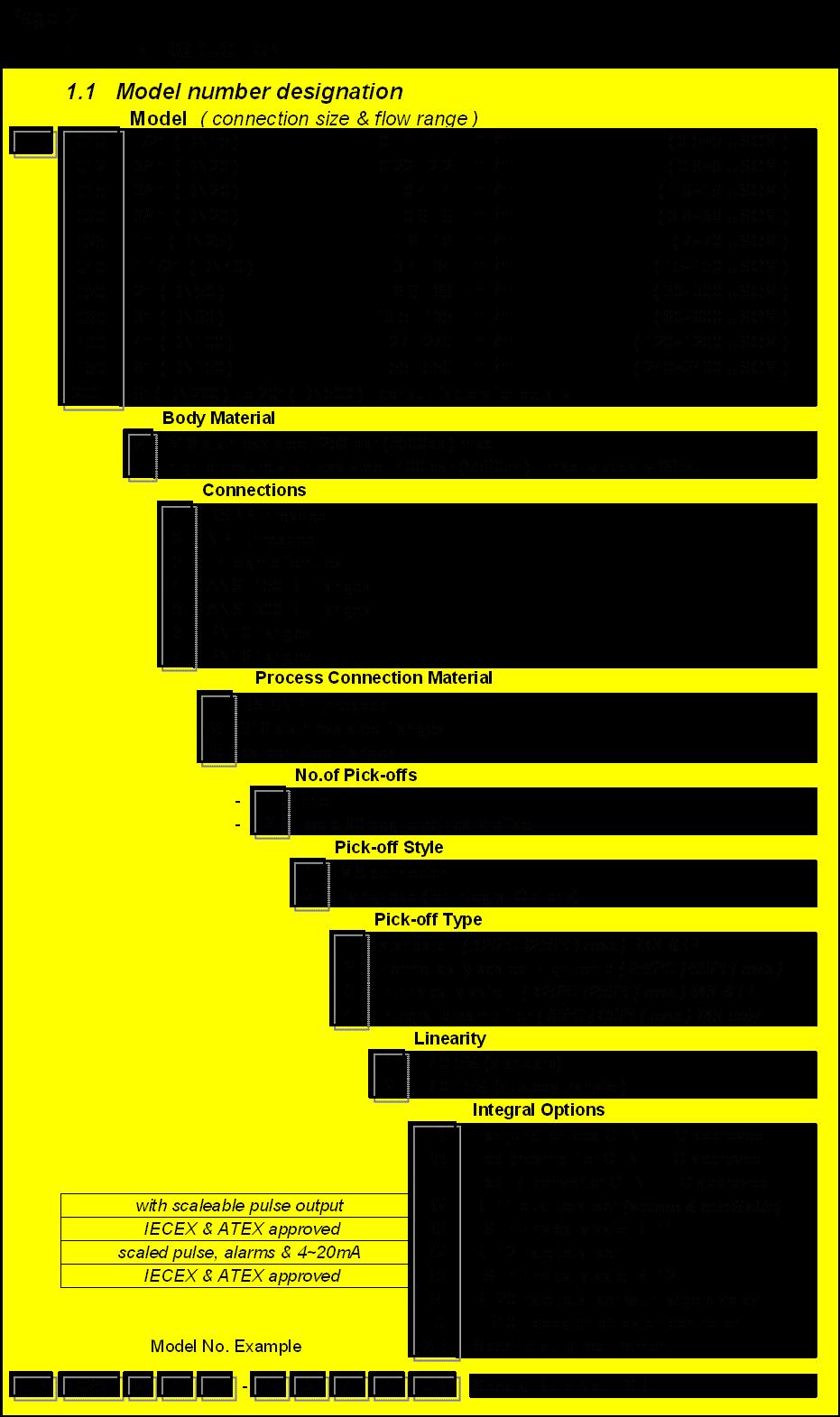
1 TURBOPULSE TURBINE FLOWMETER INSTRUCTION MANUAL gal RUN ACCUM. TOTAL STOP BAT LOW HIGH RESET > PROGRAM ENTER ACCUM TOTAL ^ RATE TOTAL TP050
2 TABLE OF CONTENTS 1. INTRODUCTION Overview Model number designation Specifications Principal of operation K-factor Pressure drop Viscosity effects 4 2. INSTALLATION 2.1 Meter orientation Flow conditioning Filters Pipeline flushing Entrained air 5 3. ELECTRICAL INSTALLATION 3.1 Wiring Intrinsic safety Pre Amplifier coil Integral frequency to current converter 7 4. OPERATION 4.1 Commissioning Cleaning in place ( CIP ) 8 5. MAINTENANCE 5.1 Replacing pick-off coil Disassemble Re-assembly 8 6. SPARE PARTS 9
3 Page 1 OVERVIEW The Turbopulse is a high accuracy turbine meter used to measure the flow of low viscosity liquids. The basic meter is available with a frequency output (mv sine wave) or a pre-amplified square wave output (4 & 20mA pulse). These meters have MS (military style) plug/socket or junction box with terminals for the pulse output connections. Alternatively the meter can be supplied fitted with integral instruments such as the BT totaliser, RT flow rate totaliser or EB batch controller. If your meter is fitted with an instrument refer to the relevant instruction manual for details of the outputs & functions available.
4
5 Page Specifications Sizes : 15 models from 15mm ~ 500mm ( ½" ~ 20", DN15 ~ DN500 ) [ see model No. designation for information on available sizes ] Body material : 316 SS (1.4401) Flow ranges * : Viscosity limit : Accuracy : Repeatability : Max. pressure : Temp. range : Pressure drop : Rotor material : 0.11~1.1 m3/hr to 700~7000 m3/hr (0.5~5 USGPM to 3000~30000 USGPM) [ see model No. designation for information on available sizes ] * All meters will tolerate flowrates to125% of maximum for short runs 10 cst recommended maximum to maintain linear flow range +/- 0.5% of reading over 10:1 range as standard, +/- 0.15% range optional for sizes 100mm (4", DN100) and larger. Accuracy over the full flow range is improved to within +/-0.2% when utilising the linearisation feature of the optional RT flow rate totaliser +/ to 0.05% under steady flow conditions Threaded versions to 250 bar (3675 psi), flanged meters according to flange specification -50~120ºC (-58~250ºF), optional 240ºC (465ºF) max. Approximately 0.28 bar (4psi) at maximum flow (SG=1.0, Vis.=1 cst) ANSI 431 or SS 430/410 where cast Bearing support : 316 SS (1.4401) Bearings : Output (std.) : Preamplifier : Environmental Tungsten carbide sleeve Reluctance type pick-off coil (40 mv P/P at minimum flowrate), 20 metres maximum transmission distance Two wire 4~20mA current pulse modulated (12~24vdc), 3000 metres maximum transmission distance IP66 (Nema 4). I.S. Intrinsically safe option.
6 Page Principal of operation The Turbopulse turbine flowmeter consists of a helically shaped turbine rotor supported in two tungsten carbide bearings, the rotor being solid ferritic stainless steel of a grade compatible with the metered liquid, all contained within a housing of non-magnetic stainless steel. A pick off coil having a permanent magnet core is mounted in the housing adjacent to the rotor blade tips such that a magnetic circuit is set up via the rotor blades (fig.1). Rotation of the rotor varies the reluctance of this magnetic circuit and the flux changes induce a small voltage in the coil, the frequency of which is directly proportional to the rotor speed and therefore proportional to the volumetric flow rate. Flow circulation ports Sleeve bearing Fig. 1 Rotor shaft & rotor Pick off coil Bearing supports Circlip Thrust plate 1.4 K-factor Referring to the typical performance curve it will be seen that pulses per unit volume are almost constant over a wide range of flowrates and it is thus possible to establish a meter K-factor (pulses per unit of volume or mass) by which the output pulse must be divided in order to register meaningful engineering units on the associated electronic register / integrator. Linearity figures vary according to the size of the meter and the metered liquid conditions but are generally within +/- 0.5% of reading with point repeatability of +/- 0.1% of reading. Linearity over the full flow range is improved to within +/- 0.2% of reading when utilising the linearisation program feature of the optional RT flow rate totaliser. 1.5 Pressure drop As would be expected with any device with a fixed cross sectional area the pressure drop across the meter varies as the square of the flowrate, for Turbopulse this figure is approximately 0.28 bar (4 psig) on water flow at maximum flowrate for each size meter. 1.6 Viscosity effects The effects of increasing viscosity reduce the linear flowrange, the lower end flow rate is to be raised as the viscosity increases with a maximum viscosity of 10cSt. To calculate the low end accurate flow rate limit use: 0.7 x the square root of the metered liquid viscosity in cst x normal minimum flow rate. Eg. If normal flow range is 10~100 l/min then for viscosity of 5 cst time minimum accurate flow rate would be l/min. ( 0.7 viscosity [cst ] ) x normal min. flowrate
7 2. INSTALLATION Page Meter orientation The meter may be installed in horizontal or vertical pipes, with vertical pipes it is preferred to have the flow passing upward so that any entrained air bubbles will pass quickly. Ensure that the arrow on the meter body is in line with the direction of flow. 2.2 Flow conditioning All turbine flowmeters should be installed with a minimum of ten diameters of straight pipe upstream and five diameters down-stream (fig. 2), except where the flowmeter is installed directly after a valve or centrifugal pump when the minimum straight up-stream length should be increased to 20 diameters. Bends & elbows up-stream of the flowmeter should have a minimum inside radius of twice the diameter of the pipe. Ensure flange gaskets are bore size matched with meter. Fig. 2 min. 5 pipe diameters min. 10 pipe diameters Fig. 3 22~30º Reducers where necessary should be of the concentric Type with an included angle of 22~30 degrees (fig. 3) Inlet pipe bore should be matched as closely as possible to that of the meter, but where it is not possible to select the exact inside diameter, a smaller inlet diameter should be used in order to avoid a sharp step at the meter inlet which would cause liquid swirl effecting metering accuracy. 2.3 Filters Whilst most plants requiring precision turbine flowmeters will usually be protected by adequate filters or strainers, the recommended mesh sizes for protection of Turbopulse meters are: Sizes up to 50mm 0.3mm ( 300 microns or 60 mesh ) Sizes 80mm bore & above 0.5mm ( 500 microns or 100 mesh ) 2.4 Pipeline flushing If the Turbopulse meter is installed into a newly fabricated pipe system, the up-stream system must be purged of foreign matters such as welding slag, sealing compounds and other solid materials before installing the flowmeter. Failure to do so may result in serious damage. 2.5 Entrained Air Any turbine flowmeter will register the total amount of fluid passing whether this be all liquid or a mixture of liquid & gases and it is therefore essential to ensure that the pipeline at the meter is completely filled with liquid. Avoid spinning the rotor at speed with air or gas during start up
8 Page 6 3. ELECTRICAL INSTALLATION 3.1 Wiring Most meters are ordered with the standard non-amplified pick-off coil which produces a flow proportional millivolt sine wave signal between 15~1500mV. Connection to the standard coil output is two wire and insensitive to polarity. The pick-off coil may be tested by measuring the resistance between the two leads, the reading should be between 700~1200 ohms. Because of the low strength of the standard coil mv output it is important to protect the transmitted signal from any form of electrical interference such as AC line frequencies. A twin core ( twisted pair ) screened multi-strand signal cable should be used for connection to the pickoff coil, recommended cable size being 16/0.2 x 0.5mm² ( 16/ ). The screen needs to be connected at -0V at receiving instrument. Cable runs for non amplified outputs should be limited to 20 metres (65 feet) maximum and should be kept well away from high energy power supplies and electricals such as motor speed controllers, transformers and solenoids. Preferably run the cable in a separate conduit to any other wiring. Longer cable runs would require an amplified coil at the flowmeter. 3.2 Intrinsic safety For hazardous locations, flowmeters may be provided with intrinsically safe pick off coils which would need to be wired through an approved I.S barrier at a safe location (fig.4). Alternatively the meter can be fitted with an I.S. instrument such as RT rate totaliser or BT totaliser. Pick-off coil screen twisted pair Receiving instrument screen use twisted pair Fig. 4 Receiving instrument coil output with MS connector ( A & B ) I.S. pick off coil screen SAFE AREA MTL760ac zenner barrier screen earthed at junction box & connect to -0V at receiving instrument coil output with junction box
9 Page Preamplifier coil ( optional ) An amplified output can be provided by fitting a pre-amplified coil, or amplifier in junction box (PA option). The pre-amplifier coil amplifies the low level signal from the integral magnetic pick-off providing a current pulsed output suitable for transmission over long distances or through noisy electrical environments. The output is a current pulse in the order of 4mA (off) and 20mA (on). + 9~24Vdc - Receiving instrument A B Amplified current pulse output with MS connector. A pre-amplified output is also available from the BT or RT instruments for both general purpose & I.S. installations. 3.4 Integral frequency to current converter The integral frequency to current converter takes the millivolt signal from the flowmeter pick-off coil and converts it to a proportional 4~20mA current output signal proportional to flow rate. The F/I converter has a two wire connection to the pick-off coil in the junction box, and is two wire current loop powered (4~20mA) output to the receiving instrument. Alternatively a 4~20mA loop powered output is available from the RT (rate totaliser) instrument. Load Caution : Connection should only be made whilst there is no power on the loop. + 24vdc power supply - screen earthed at receiving end only
10 Page 8 4. OPERATION 4.1 Commissioning Immediately after installation or after long periods of shut down, the meter must be slowly purged of air. Valves should be opened slowly until the meter and upstream pipe work is completely filled with liquid in order to prevent over speeding the rotor. 4.2 Cleaning in place ( CIP ) When a system is to be cleaned in line, sterilised or purged without removal of the meter from the pipeline, it is advisable to provide a by-pass around the meter to avoid damage to the rotor and bearings, unless the following recommendations can be adhered to: * The cleaning liquids must be compatible with the materials of the meter. * When steam sterilising, ensure that the steam temperature does not exceed the maximum operating temperature of the meter. The velocity of steam must be carefully restricted so that the speed of the turbine is kept below the speed of maximum flow rate on liquids. The same restrictions apply when purging with air or gas. 5 MAINTENANCE 5.1 Replacing pick-off coil When replacing the pick-off coil it must be hand tightened only, avoid using a wrench or pliers. 5.2 Disassemble All internals are disassembled in turn through the end of the meter body. Take special note of the position and varying diameters of the two bearing supports so that these may be replaced in the same position and reverse sequence during re-assembly. There are several different forms of retainment of the internals, these are dependant on meter size. Sizes 15~50mm (1/2 ~2 ) use a circlip, 80mm (3 ) has a retaining ring and larger sizes use a slotted locking tab and hub nut. Always use a soft aluminium drift and light hammer when removing the bearing supports. Use a pencil or felt pen to mark the bearing supports and rotor with the flow direction to assist in re-assembly. 5.3 Re-assembly Re-assemble the internals in the reverse order giving particular to the flow direction of the rotor, the leading edge of the rotor blades are angled and the trailing edges are squared off (fig. 5). Fig. 5 Rotor trailing edge (squared) Bearing supports Rotor leading edge (angled) FLOW DIRECTION
11 Page 9 6 SPARE PARTS Calibrated measuring element assembly Suit meter Part No. TP010 MEA010 Rotor & shaft, Bearings and bearing supports + circlip TP012 MEA012 TP015 MEA015 TP020 MEA020 Note: The calibrated measuring elements are TP025 MEA025 supplied with a new calibration report TP040 MEA040 which in most cases will have a new K-factor TP050 MEA050 than that of the original meter elements. TP080 MEA080 TP100 MEA100 TP150 MEA150 Pick off Coils Standard pick off coil to 120ºC (250ºF) with MS connector pins Standard pick off coil to 120ºC (250ºF) with flying leads I.S. pick off coil to 120ºC (250ºF) with MS connector pins I.S. pick off coil to 120ºC (250ºF) with flying leads Pre-amplified current modulated pick off coil with MS connector 65ºC (150ºF) Herm sealed, High temp. pick off coil to 240ºC (460ºF) with leads Herm sealed, High temp. pick off coil to 240ºC (460ºF ) with MS connector pins Part No. PC-802-MS PC-802-FL PCI-802-MS PCI-802-FL PUA-8700-MS PC-55-9G PC55-8G
12 IMTP
INSTALLATION AND OPERATION
 Industrial Type Turbine Flowmeter NT Hygienic Type Turbine Flowmeter BNO Low Flow Pelton Wheel Flowmeter NS INSTALLATION AND OPERATION Nixon Flowmeters Ltd. Leckhampton, Cheltenham, Glos UK Tel. 0044 (0)
TR-QS Wafer-Style Turbine Flow Meters Installation, Operating & Maintenance Manual
 COMPANY TR-QS Wafer-Style Turbine Flow Meters Installation, Operating & Maintenance Manual 2016 AW-Lake Company. All rights reserved. Doc ID:TRQSMAN16 Table of Contents Contents Table of Contents... 2
Sanitary Turbine Flow Meter - TA3 Installation, Operating & Maintenance Manual
 COMPANY Sanitary Turbine Flow Meter - TA3 Installation, Operating & Maintenance Manual 2016 AW-Lake Company. All rights reserved. Doc ID:SANITARYMAN16 Mechanical Specifications Measuring Accuracy ± 1.0%
QUALITY INDUSTRIAL FLOWMETERS
 QUALITY INDUSTRIAL FLOWMETERS COMPANY PROFILE Trimec Industries is an Australian owned ISO9001:2008 quality certified company specializing in the design and manufacture of a proprietary range of positive
Insertion turbine INSTRUCTION SHEET. TECHNICAL PRODUCT
 TECHNICAL PRODUCT INSTRUCTION SHEET Insertion turbine OVERVIEW These insertion flow transducers provide a cost effective and simple means of measuring the flow of a wide range of low viscosity liquids.
BI-DIRECTIONAL INSERTION FLOW TRANSDUCER
 DUALPULSE BI-DIRECTIONAL INSERTION FLOW TRANSDUCER INSTRUCTION MANUAL DUALPULSE LOCK 1.1 General arrangement Thank you for purchasing a Dualpulse Flowmeter. It is important that you read this manual to
MODEL 1100 TURBINE FLOW METER
 MODEL 1100 TURBINE FLOW METER INSTALLATION & INSTRUCTION MANUAL 8635 Washington Ave. Racine, Wisconsin 53406 Phone: 800.433.5263 Fax: 800.245.3569 www.hedland.com 2 OPERATIONAL START-UP Fluid entering
Flow Sensors & Instruments
 STAINESS STEE TURBINE FOWMETERS Serie X IG PRESSURE AND IG TEMPERATURE Principle of Operation The x range of Turbine Flowmeters meet the demand of most liquid measurement applications. They basically consist
BI-DIRECTIONAL INSERTION METER
 BI-DIRECTIONAL INSERTION METER INSTRUCTION MANUAL LOCK 1 Contents CONTENTS PAGE 1.0 INTRODUCTION 1.1 General arrangement 2 1.2 Overview 3 1.3 Operating principal 3 1.4 Specifications 3 2.0 INSTALLATION
Positive displacement flowmeter for continuous flow measurement
 8070 Positive displacement flowmeter for continuous flow measurement High accuracy Medium with high viscosity Mounting and dismounting of the electronics by a quarter-turn Connection to Bürkert devices
PA - Turbine Flowmeter Range
 PA - Turbine Flowmeter Range PA - Turbine Flow Meter Range Our PA - Turbine Flow Meters have a unique open bearing design which allows the measured media to flow freely thru the bearings and therefore
Model 1100 Turbine Flow Meter
 Model 1100 Turbine Flow Meter INSTALLATION & INSTRUCTION MANUAL 8635 Washington Avenue Racine, Wisconsin 53406 Tel: 800-433-5263 or 262-639-6770 Fax: 800-245-3569 or 262-639-2267 www.hedland.com TABLE
Type 2712 (8630) Continuous TopControl System. General data Compatibility Materials of wetted parts Body Rotor Shaft Seal
 Continuous TopControl System. General data Compatibility Materials of wetted parts Body Rotor Shaft Seal") Positive displacement flow fitting for continuous and batch control High accuracy ± 0.5% 1/2 TO 4 (DN 15 to 100) INLINE Quarter Turn technology For highly viscous fluids Electronics for indication, monitoring,
Positive displacement flow fitting for continuous and batch control High accuracy ± 0.5% 1/2 TO 4 (DN 15 to 100) INLINE Quarter Turn technology For highly viscous fluids Electronics for indication, monitoring,
QUALITY INDUSTRIAL FLOWMETERS
 QUALITY INDUSTRIAL FLOWMETERS COMPANY PROFILE Trimec Industries is an Australian owned ISO9001:2008 quality certified company specializing in the design and manufacture of a proprietary range of positive
I N S T R U C T I O N M A N U A L
 I N S T R U C T I O N M A N U A L Oval Gear Positive Displacement Mechanical Flowmeters Models: 3 (080), 3 (080E), 4 (100), 4 (100E) NSW TEL: (02) 9939 0711 FAX: (02) 9939 0411 QLD/PNG TEL: (07) 3204 9166
High Performance Turbine Technology
 The Brooks Parity Turbine Meter Sizes 3" - 16" High Performance Turbine Technology Design Specifications DS2215-10 July, 1999 DESCRIPTION The Parity Turbine Flowmeter utilizes advanced turbine meter technology
Turbine flowmeters Series TM
 Turbine flowmeters Series TM Suitable for liquids Possibility of installation in all flow directions Special design for high pressure available Excellent relationship flow range / flowmeter size Low pressure
FLOWX3 F3.20 High Pressure Paddlewheel Flow Sensor MAIN FEATURES APPLICATIONS OPERATING PRINCIPLE
 FLOWX3 F3.20 High Pressure Paddlewheel Flow Sensor FlowX3 F3.20 is a paddlewheel flow sensor suitable for system at high pressure and at critical temperature. F3.20 is designed for use with every kind
PSF50 Paddle flow switch
 Paddle Flow Switch Paddle Flow Switch PSF50 Paddle flow switch Paddle flap flow / no flow switch Economically priced flow/no flow paddle operated flow switch. Simple and reliable design for liquids up
Turbine Flow Meter Range
 Turbine Flow Meter Range Our Turbine Flow Meters have a unique open bearing design which allows the measured media to flow freely thru the bearings and therefore provides continuous lubrication. This prolongs
Liquid Turbine Flowmeter
 NUFLO Liquid Turbine Flowmeter User Manual 167018 Explosion-proof for use in Class I, Division I, Groups A, B, C, D Hazardous Environments ANSI 12.27.01-2003 Single Seal Part No. 9A-100062201, Rev. 01
flow measurement solutions RIM10 series rotor insertion flowmeters
 flow measurement solutions RIM10 series rotor insertion flowmeters R I M 1 0 RIM10 series rotor insertion flowmeters Versatile enough for almost any challenge Spirax Sarco s RIM10 rotor insertion flowmeters
OVAL GEAR. Large Capacity Positive Displacement Mechanical Flowmeters. Models: 3 (D-750), 3 (D-1000), 4 (D-1500) & 4" (D-2500)
, 3 (D-1000), 4 (D-1500) & 4 (D-2500)") OVAL GEAR Large Capacity Positive Displacement Mechanical Flowmeters INSTRUCTION MANUAL Models: 3 (D-750), 3 (D-1000), 4 (D-1500) & 4" (D-2500) Index / contents 1 1.0 General Page 1.1 Overview 2 1.2 Operating
OVAL GEAR Large Capacity Positive Displacement Mechanical Flowmeters INSTRUCTION MANUAL Models: 3 (D-750), 3 (D-1000), 4 (D-1500) & 4" (D-2500) Index / contents 1 1.0 General Page 1.1 Overview 2 1.2 Operating
OVAL GEAR. Medium capacity positive displacement Pulse flowmeters I N S T R U C T I O N M A N U A L
 OVAL GEAR Medium capacity positive displacement Pulse flowmeters I N S T R U C T I O N M A N U A L Models: 1 (D-150), 1½ (D-250), 2 (D-450) & 2" (D-580) (Extended flow range) Index / contents 1 1.0 General
Positive Displacement Flowmeters GM020 series instruction manual
 ACCURATE FLOWMETERS & INSTRUMENTATION PVT. LTD. Positive Displacement Flowmeters GM020 series instruction manual GM020 Pulse Meter From serial No. CXXXX Accurate Flowmeters & Instrumentation Pvt. Ltd.
OM SERIES OVAL GEAR METERS. OM SERIES Oval Gear Meters
 Oval Gear Meters OVAL GEAR METERS OM Series Oval Gear Meters are designed for low flow and high accuracy. OM Series Meters are great for viscous fluids. Units are available with from either a Reed Switch
RPFS. ROTA PULSE FLOW SENSOR (Slip Insertion Paddlewheel) DATASHEET FEATURES
 DATASHEET FEATURES") FEATURES ROTA PULSE FLOW SENSOR (Slip Insertion Paddlewheel) DATASHEET ± 2.5% accuracy @ velocity range 0.5 to 8.5 m/sec. ± 1 % accuracy over linear range 0.7 to 7.0 m/sec. Repeatability of ±0.6%. NPN
FEATURES ROTA PULSE FLOW SENSOR (Slip Insertion Paddlewheel) DATASHEET ± 2.5% accuracy @ velocity range 0.5 to 8.5 m/sec. ± 1 % accuracy over linear range 0.7 to 7.0 m/sec. Repeatability of ±0.6%. NPN
G2 Industrial Grade Meters
 G2 Industrial Grade Meters The unique modular approach of the Industrial Grade Meter line allows you to section 2: g2 industrial grade meters design a meter to match your specific application. Turbine
OVAL GEAR FLOWMETER ELECTRONIC MODEL 019 / ¾
 INST-019P_R4 11/2012 OVAL GEAR FLOWMETER ELECTRONIC MODEL 019 / ¾ INSTRUCTION MANUAL To the Owner PLEASE READ THIS SAFTEY INFORMATION CAREFULLY BEFORE USE. Read and retain this instruction manual to assist
ZTM AND ZTMB ZENNER TURBINE METERS INSTALLATION, MAINTENANCE AND SERVICING
 ZTM AND ZTMB ZENNER TURBINE METERS INSTALLATION, MAINTENANCE AND SERVICING INSTALLATION 1. The meter is intended for measuring potable, cold water in one direction. 2. The meter is to be installed in a
Sanitary Sensors. High Quality, Precision. Sanitary Sensors. THORNTON Leading Pure Water Analytics
 THORNTON Leading Pure Water Analytics Sanitary Sensors Sanitary Sensors Temperature Sensors 3A Sanitary Turbine Flow Sensors Pressure Sensors Tank Level Sensors High Quality, Precision Sanitary Sensors
OVAL GEAR Medium capacity positive displacement Mechanical flowmeters. Model: ½ (15m m)
") OVAL GEAR Medium capacity positive displacement Mechanical flowmeters INSTRUCTION MANUAL Model: ½ (15m m) Index / contents 1 1.0 General Page 1.1 Overview 2 1.2 Operating principal 3 1.3 Specifications
OVAL GEAR Medium capacity positive displacement Mechanical flowmeters INSTRUCTION MANUAL Model: ½ (15m m) Index / contents 1 1.0 General Page 1.1 Overview 2 1.2 Operating principal 3 1.3 Specifications
I N S T R U C T I O N M A N U A L 3 (080), 3 (080E), 4 (100), & 4 (100E)
, 3 (080E), 4 (100), & 4 (100E)") SEE OVER OVAL GEAR Large capacity positive displacement Mechanical Flowmeters I N S T R U C T I O N M A N U A L Models: 3 (080), 3 (080E), 4 (100), & 4 (100E) Index / contents 1 1.0 General Page 1.1 Overview
SEE OVER OVAL GEAR Large capacity positive displacement Mechanical Flowmeters I N S T R U C T I O N M A N U A L Models: 3 (080), 3 (080E), 4 (100), & 4 (100E) Index / contents 1 1.0 General Page 1.1 Overview
DUALPULSE BI-DIRECTIONAL INSERTION FLOW TRANSDUCER INSTRUCTION MANUAL IMDP DUALPULSE LOCK
 BI-DIRECTIONAL INSERTION FLOW TRANSDUCER INSTRUCTION MANUAL IMDP000-3310 Contents 1 1.1 General arrangement Thank you for purchasing a Dualpulse Flowmeter. It is important that you read this manual to
Condensed Version of Operator s Manual For The VI/VP700 Series Flowmeter and VI800 Series Flowmeter
 Condensed Version of Operator s Manual For The VI/VP700 Series Flowmeter and VI800 Series Flowmeter Warranty Agreement J-TEC Associates warrants this product to be in good working order for a period of
MX06 - MX100 OVAL GEAR FLOWMETER SERIES APPROVED FOR USE IN HAZARDOUS AREAS
 MXEX-INST Rev 9.0 04/2016 MX06 - MX100 OVAL GEAR FLOWMETER SERIES APPROVED FOR USE IN HAZARDOUS AREAS INSTRUCTION MANUAL To the Owner Page 1 of 33 index Installation Pre-installation checks. Page 3 Operating
OVAL GEAR. Medium Capacity Positive Displacement Mechanical Flowmeters. Models: 1 (D-150), 1½ (D-250), 2 (D-450) & 2" (D-580)
, 1½ (D-250), 2 (D-450) & 2 (D-580)") OVAL GEAR Medium Capacity Positive Displacement Mechanical Flowmeters INSTRUCTION MANUAL Models: 1 (D-150), 1½ (D-250), 2 (D-450) & 2" (D-580) Index / contents 1 1.0 General Page 1.1 Overview 2 1.2 Operating
OVAL GEAR Medium Capacity Positive Displacement Mechanical Flowmeters INSTRUCTION MANUAL Models: 1 (D-150), 1½ (D-250), 2 (D-450) & 2" (D-580) Index / contents 1 1.0 General Page 1.1 Overview 2 1.2 Operating
I N S T R U C T I O N M A N U A L
 OVAL GEAR Medium Capacity positive displacement Pulse flowmeters I N S T R U C T I O N M A N U A L Model: 1/2 (D-40) Index / contents 1 1.0 General Page 1.1 Overview 2 1.2 Operating principal 2 1.3 Specifications
ManuFlo Page 1 MANU ELECTRONICS PTY LTD Flow Measurement Products Rev PK KMS501W & KMS502F- TW. Electromagnetic TRADEWASTE Flowmeters FEATURES:
 KMS501W & KMS502F- TW FEATURES: Fitted with Sydney Water Tradewaste plugs (Sampler and ma outputs). For waste water, bore water and irrigation ( upto 10% solids). Unsurpassed accuracy to ±0.5% 0.5 m/s
OVAL GEAR Medium capacity positive displacement flowmeters
 Each meter has been calibrated on mineral oil and will contain a small amount of oil residue. The oil used is Castrol Diesel Calibration Fluid 4113 (product code 055830). SEE OVER OVAL GEAR Medium capacity
VLM20 In-line Vortex Flowmeter
 ocal regulations may restrict the use of this product to below the conditions quoted. In the interests of development and improvement of the product, we reserve the right to change the specification without
EZ-IN Series Turbine Flowmeter
 Class I, Group A, B, C, D, Division I Complies with ASME Standard B31.3 NUFLO EZ-IN Series Turbine Flowmeter Installation Manual Part No. 9A-100062997, Rev. 01 Measurement Systems EZ-IN Series BF Turbine
Positive Displacement Flowmeters GM020 series instruction manual
 MS244G 0603 0003 Positive Displacement Flowmeters GM020 series instruction manual GM020 Pulse Meter From serial No. CXXXX To the owner Thank you for purchasing a GPI GM Series Flow Meter. Please take a
FLS F6.60 MAGMETER FLOW SENSOR INSERTION FLOW SENSORS APPLICATIONS MAIN FEATURES
 FLS F6.60 MAGMETER FLOW SENSOR The new F6.60 and F6.63 are flow meters without moving mechanical parts which can be applied for the measurement of dirty liquids so long as they are conductive and homogeneous.
Liquid Turbine Flow Meter OwnerÊs Manual
 Liquid Turbine Flow Meter OwnerÊs Manual Manual LWGY-G Rev.1.0 Content 1.0 GENERAL INFORMATION... 1 2.0 SPECIFICATIONS... 2 3.0 OPERATION CONDITIONS... 3 4.0 CAUTIONS FOR INSTALLATION... 4 5.0 DIMENSION...
FPD1001B thru FPD1003B, FPD1102B and FPD1103B, FPD1201B thru FPD1203B SERIES LOW FLOW Positive Displacement Flowmeters
 FPD1001B thru FPD1003B, FPD1102B and FPD1103B, FPD1201B thru FPD1203B SERIES LOW FLOW Positive Displacement Flowmeters To the owner: Please take a few minutes to read through the manual before installing
Model 1000 Vortex Meter
 Model 1000 Vortex Meter Installation and Instruction Manual Table of Contents General Information... 1 1-1 General... 1 1-2 Principles of Operation... 1 1-3 Sensor Operation... 1 1-4 Calibration Factor...
INLINE Flow sensor for hazardous area II 1 G/D - II 2 D - II 3 GD - I M1
 INLINE Flow sensor for hazardous area II G/D - II D - II GD - I M Type SE0 Ex can be combined with... Flow meter with NAMUR or NPN/PNP output signal Mounting, dismounting of electronics by a Quarter-Turn
OPTIFLUX 6000 Technical Datasheet
 OPTIFLUX 6000 Technical Datasheet Electromagnetic flow sensor for hygienic and sanitary applications Robust stainless steel housing for hygienic and aseptic operation Fully suitable for CIP and SIP Typical
Satellite photo of cloud vortices caused by a mountain (Courtesy of our friends at NASA) tekvorx Operation Showing Simplified Construction
 tekvorx Operation Showing Simplified Construction") Sensing the pulse of industry tekvorx TV01 Multivariable Vortex flow Sensors Vortex flow sensors derive their name from a natural phenomenon of fluid dynamics. When a gas or relatively low viscosity liquid
Sensing the pulse of industry tekvorx TV01 Multivariable Vortex flow Sensors Vortex flow sensors derive their name from a natural phenomenon of fluid dynamics. When a gas or relatively low viscosity liquid
7000 Series Liquid Turbine Meters
 BARTON 7000 Series Liquid Turbine Meters Models 71, 7, & 73 Barton 7000 series turbines are designed for a broad range of precise liquid measurement applications. Based on 35 years of turbine manufacturing,
MODEL 1100 TURBINE METER REPAIR KITS
 MODEL 1100 TURBINE METER REPAIR KITS REPAIR MANUAL Rev. B 52 NW 42 nd Street Oklahoma City, OK 73118 Phone: (405) 525-6601 Kimray.com GENERAL DESCRIPTION The Kimray Model 1100 turbine flow meter is designed
MULTIPULSE SAP SUPER ACID PROOF POSITIVE DISPLACEMENT FLOWMETER
 MULTIPULSE SP SUPER CID PROOF POSITIVE DISPLCEMENT FLOWMETER models : MP010P & MP020P INSTRUCTION MNUL TRIMEC INDUSTRIES Pty.Ltd. 1 / 19 Northumberland Road Caringbah NSW 2229 Sydney - USTRLI Tel : +61
Daniel Liquid Turbine Flow Meter Technical Guide
 Liquid Turbine Flow Meters Daniel Liquid Turbine Flow Meter Technical Guide www.daniel.com TABLE OF CONTENTS Turbine Meter Parameters...1 The Daniel Series 1200 and 1500 Liquid Turbine Flow Meter Systems...
Electro-Magnetic Flowmeters Sensors MagMaster MFE
 Data Sheet (US) Electro-Magnetic Flowmeters Sensors MagMaster MFE Unrivalled flow performance ±0.2% accuracy. Pulsed DC Technology Incorporates Benefits of AC Systems Operable flow range of 1000:1. Two-year
ROTA PULSE FLOW SENSOR Slip Insertion Paddlewheel (with inductive coil pulse output & built in op-amp circuit)
") FEATURES ROTA PULSE FLOW SENSOR Slip Insertion Paddlewheel (with inductive coil pulse output & built in op-amp circuit) DATASHEET ± 2.5% accuracy @ velocity range 0.5 to 8.5 m/sec. ± 1.5% accuracy over
FEATURES ROTA PULSE FLOW SENSOR Slip Insertion Paddlewheel (with inductive coil pulse output & built in op-amp circuit) DATASHEET ± 2.5% accuracy @ velocity range 0.5 to 8.5 m/sec. ± 1.5% accuracy over
IP800-Series FLOW SENSOR INSTRUCTIONS IP810 IP :2008 ISO CERTIFIED COMPANY IP80-SERIES FLOW SENSOR INSTRUCTIONS
 IP80-SERIES FLOW SENSOR INSTRUCTIONS IP800-Series FLOW SENSOR INSTRUCTIONS IP810 IP820 9001:2008 ISO CERTIFIED COMPANY TABLE OF CONTENTS General Information Features, Specifications...Page 3 Installation
IP80-Series FLOW SENSOR INSTRUCTIONS IP81 IP :2008 ISO CERTIFIED COMPANY IP80-SERIES FLOW SENSOR INSTRUCTIONS
 IP80-SERIES FLOW SENSOR INSTRUCTIONS IP80-Series FLOW SENSOR INSTRUCTIONS IP81 IP82 9 001:2008 ISO CERTIFIED COMPANY TABLE OF CONTENTS General Information Features, Specifications...Page 3 Installation
A1 Commercial Grade Meters
 A1 Commercial Grade Meters Commercial Grade Meters are designed as self-contained, battery powered units. These indicating meters come in Aluminum or Nylon only. A1 Meters are not field serviceable like
Field IT Electro-Magnetic Flowmeters Sensors
 Data Sheet Field IT Electro-Magnetic Flowmeters Sensors MagMaster MFE Unrivalled flow performance ±0.2% accuracy. Pulsed DC Technology Incorporates Benefits of AC Systems Operable flow range of 1000:1.
RIM20 Rotor Insertion Flowmeter
 Local regulations may restrict the use of this product to below the conditions quoted. In the interests of development and improvement of the product, we reserve the right to change the specification without
OVAL GEAR FLOWMETER MECHANICAL MODEL 012 (½ )
") INST-012M_R4 11/2012 OVAL GEAR FLOWMETER MECHANICAL MODEL 012 (½ ) INSTRUCTION MANUAL To the Owner PLEASE READ THIS SAFTEY INFORMATION CAREFULLY BEFORE USE. Read and retain this instruction manual to assist
INST-012M_R4 11/2012 OVAL GEAR FLOWMETER MECHANICAL MODEL 012 (½ ) INSTRUCTION MANUAL To the Owner PLEASE READ THIS SAFTEY INFORMATION CAREFULLY BEFORE USE. Read and retain this instruction manual to assist
IP800-Series FLOW SENSOR INSTRUCTIONS IP810 IP :2008 ISO CERTIFIED COMPANY IP800-SERIES FLOW SENSOR INSTRUCTIONS
 -SERIES FLOW SENSOR INSTRUCTIONS -Series FLOW SENSOR INSTRUCTIONS IP810 IP820 9001:2008 ISO CERTIFIED COMPANY TABLE OF CONTENTS General Information Features, Specifications...Page 3 Installation Insertion
GPM Hydraulic Flow Meter User Manual
 4278 100 GPM Hydraulic Flow Meter User Manual Introduction The OTC 4278 Hydraulic Flow Meter has been designed for easy connection to a hydraulic circuit so that flow, pressure and temperature can be readily
Pipe fi ttings MUST be installed by a certifi ed welder only. Signet will not assume liability of any kind for improper fi tting installations.
 Signet 50 High Performance Flow Sensor English *3-50.090* 3-50.090 C 05/06 English SAFETY INSTRUCTIONS 1. Do not remove from pressurized lines.. Do not exceed maximum temperature/pressure specifi cations.
tekson TS Series Low Cost Ultrasonic Water Energy Flow Measurement
 Sensing the pulse of industry tekson TS Series Low Cost Ultrasonic Water Energy Flow Measurement tekflo sensors are proud to present their tekson TS Series ultrasonic water energy meter, which uniquely
Industrial Turbo Meters, Sizes 2" through 6"
 Industrial Turbo Meters Sizes 2" through 6" TUR-UM-00530-EN-19 (October 2014) User Manual Industrial Turbo Meters, Sizes 2" through 6" User Manual CONTENTS Scope of the Manual 5 Specifications 5 Product
OVAL GEAR FLOWMETER MECHANICAL MODEL 075 (3 )
") INST-075M_R4 11/2012 OVAL GEAR FLOWMETER MECHANICAL MODEL 075 (3 ) INSTRUCTION MANUAL To the Owner PLEASE READ THIS SAFTEY INFORMATION CAREFULLY BEFORE USE. Read and retain this instruction manual to assist
INST-075M_R4 11/2012 OVAL GEAR FLOWMETER MECHANICAL MODEL 075 (3 ) INSTRUCTION MANUAL To the Owner PLEASE READ THIS SAFTEY INFORMATION CAREFULLY BEFORE USE. Read and retain this instruction manual to assist
Trimec Flow Products Pty. Ltd. Tel : /51 Kalman Drive, Fax : Effective : August 2013
 Page 1 E:\TrimecFP Pricelist_RevB_APR 30 2014.xls PRICE LIST Trimec Flow Products Pty. Ltd. Tel : + 612 9937 1811 21/51 Kalman Drive, Fax : + 612 9729 1960 Boronia, Vic., 3155 Australia Email : sales@trimecifp.com.au
KOBOLD DF-MA Flow Transmitter. User Instructions
 KOBOLD DF-MA Flow Transmitter User Instructions KOBOLD Instruments Inc. 1801 Parkway View Drive Pittsburgh PA 15205 Phone (412) 788-2830 Fax (412)-788-4890 www.koboldusa.com Manual-DF-MA_12-13 DF-MA Table
Model TUR-200D Turbine Flowmeter
 General Specifications Model TUR-200D Turbine Flowmeter Liquid flows through the turbine housing causing an internal rotor to spin. As the rotor spins, an electrical signal is generated in the pickup coil.
Inline Ultrasonic Flowmeter
 M-1500 Series Installation and Operating Manual The M-1500 series is an inline primary flow sensor and externally mounted controller unit. The flow sensor is a straight through flow tube that uses Transit
Axial Turbine Flow Sensor Series Turbotron VTH 25 / VTI 25 / VTM 25
 Installation Instruction Axial Turbine Flow Sensor Series Turbotron VTH 25 / VTI 25 / VTM 25 Table of contents Page 1 Function of Turbotron 1 2 Safety instructions 2 3 Important notes and requirements
Electromagnetic flowmeters Series FLOMID Electromagnetic flowmeter for conductive liquids
 Electromagnetic flowmeters Series FLOMID Electromagnetic flowmeter for conductive liquids Flow rate measurement is independent of density, temperature, viscosity and pressure Pulsed coil excitation to
100 Series Flow Switches Technical Reference Manual
 Proteus Industries Inc. 100 Series Flow Switches Technical Reference Manual Can we Improve? Tell our President! Can we improve our product, our support or this manual? We are committed to continuous improvement
OM004, OM006 & OM008 Oval Gear Meter
 OM SERIES OM004, OM006 & OM008 Oval Gear Meter OM004 (1/8"), OM006 (1/4") and OM008 (3/8") Oval Gear Meters ACCURACY: ±1.0% OF READING Select Your Body Material: Aluminum or Stainless Steel The OM Small
RPFS. ManuFlo Page 1 MANU ELECTRONICS PTY LTD Flow Measurement Products 41 Carter Road, Brookvale NSW 2100
 FEATURES ROTA PULSE FLOW SENSOR (Slip Insertion Paddlewheel) DATASHEET ± 2.5% accuracy @ velocity range 0.5 to 8.5 m/sec. ± 1 % accuracy over linear range 0.7 to 7.0 m/sec. Repeatability of ±0.6%. NPN
Positive Displacement Flowmeters GM007 series instruction manual
 MS499G 0603 0003 Positive Displacement Flowmeters GM007 series instruction manual GM007 Pulse Meter From serial No. CXXXX To the owner Thank you for purchasing a GPI GM GPI by telephone or fax.] Series
TX80-Series FLOW SENSOR INSTRUCTIONS TX81 TX :2008 ISO CERTIFIED COMPANY TX80-SERIES FLOW SENSOR INSTRUCTIONS
 TX80-SERIES FLOW SENSOR INSTRUCTIONS TX80-Series FLOW SENSOR INSTRUCTIONS TX81 TX82 9 001:2008 ISO CERTIFIED COMPANY TABLE OF CONTENTS General Information Specifications, Features...Page 1 Installation
HTM Series Helical Turbine Meters
 HTM Series Helical Turbine Meters The HTM series of turbine meters is designed for high accuracy volume measurement of crude oils and other liquid hydrocarbons. M&T helical turbine meters are preferred
OVAL GEAR FLOWMETER ELECTRONIC MODEL 006/009 (¼ )
") INST-006/009P_R9 06/2015 OVAL GEAR FLOWMETER ELECTRONIC MODEL 006/009 (¼ ) INSTRUCTION MANUAL F Serial Meters To the Owner PLEASE READ THIS SAFTEY INFORMATION CAREFULLY BEFORE USE. Read and retain this
INST-006/009P_R9 06/2015 OVAL GEAR FLOWMETER ELECTRONIC MODEL 006/009 (¼ ) INSTRUCTION MANUAL F Serial Meters To the Owner PLEASE READ THIS SAFTEY INFORMATION CAREFULLY BEFORE USE. Read and retain this
Product Data Sheet. Turbine Flow Meter. QuikSert DESCRIPTION INSTALLATION FEATURES REPAIR KITS
 DESCRIPTION Turbine Flow Meter QuikSert The QuikSert in-line turbine flow meter was developed for liquid applications where accuracy and dependability are needed. QuikSert s stainless steel body incorporates
FPD1001 thru FPD1003, FPD1102 and FPD1103, FPD1201 thru FPD1203 (includes -R Option) Positive Displacement Flowmeters
 Positive Displacement Flowmeters") FPD1001 thru FPD1003, FPD1102 and FPD1103, FPD1201 thru FPD1203 (includes -R Option) SERIES LOW Flow Positive Displacement Flowmeters To the owner: Please take a few minutes to read through the manual
FPD1001 thru FPD1003, FPD1102 and FPD1103, FPD1201 thru FPD1203 (includes -R Option) SERIES LOW Flow Positive Displacement Flowmeters To the owner: Please take a few minutes to read through the manual
G2 SERIES INDUSTRIAL GRADE METERS
 Industrial Grade Meters INDUSTRIAL GRADE METERS The unique modular approach of the Industrial Grade Meter line allows you to design a meter to match your specific application. Turbine choice depends on
Operating Instructions for Oval Wheel Flowmeter. Model: DOC
 Operating Instructions for Oval Wheel Flowmeter Model: DOC We don t accept warranty and liability claims neither upon this publication nor in case of improper treatment of the described products. The document
Operating Manual Model- P282 Digiflow Controller
 Operating Manual Model- P282 Digiflow Controller Totalizer mode Controller 00.00 LPH 0000000.0 L t s SET SCL ENT Model- P282 Tecnical specification of flow sensor P812 Flow Rate Range : 0.5 to 5 m/s (1.6
200 Series Flow Meters
 Proteus Industries Inc. 200 Series Flow Meters Technical Reference Manual Can we Improve? Tell our President! Can we improve our product, our support or this manual? We are committed to continuous improvement
Transmitters. Differential Pressure Transmitters Pneumatic Design FOXBORO 13A D/P Cell
 Transmitters Differential Pressure Transmitters Pneumatic Design FOXBORO 13A D/P Cell Oldest design, developed during WW 2. Can be used for flow, level, and pressure, vent low side. Several ranges 0 to
Turbine Flow Meter Series Turbine Meter USER MANUAL
 Turbine Flow Meter 1100 Series Turbine Meter USER MANUAL Turbine Flow Meters, 1100 Series CONTENTS Introduction......................................................................... 3 Operating Principle....................................................................
OVAL GEAR FLOWMETER ELECTRONIC MODEL 025 / 1
 025 Puls 07.11 OVAL GEAR FLOWMETER ELECTRONIC MODEL 025 / 1 INSTRUCTION MANUAL To the Owner PLEASE READ THIS SAFTEY INFORMATION CAREFULLY BEFORE USE. Read and retain this instruction manual to assist you
Variable Area Flowmeters Ori-Flowrator TM Meters
 Data Sheet (US) Variable Area Flowmeters Ori-Flowrator TM Meters 10B4000 Low installation cost Linear indication over 12-1/2 to 1 flow range Inexpensive method of measuring large flow rates in direct flow
Paddle Wheel Turbine Flow Meters Installation, Operating & Maintenance Manual
 COMPANY Paddle Wheel Turbine Flow Meters Installation, Operating & Maintenance Manual Mechanical Specifications Flow Meter with Polypropylene Body (ES version) Maximum Operating Pressure: 150 PSIG Maximum
OVAL GEAR Medium capacity positive displacement flowmeter
 SEE OVER OVAL GEAR Medium capacity positive displacement flowmeter I N S T R U C T I O N M A N U A L Model: (1") 025P PPS Meter Index / contents 1 1.0 General Page 1.1 Overview 2 1.2 PPS Chemical Compatibility
A1 Commercial Grade Meters
 A1 Commercial Grade Meters Commercial Grade Meters are designed as self-contained, battery powered units. These indicating meters come in Aluminum or Nylon only. A1 Meters are not field serviceable like
FLOWX3 F3.60M.S Insertion Magmeter
 FLOWX3 F3.60M.S Insertion Magmeter The FLOWX3 F3.60M.S Insertion Magmeters are suitable to measure flowrate in both metal and thermoplastic pipelines. No moving mechanical parts and the high quality materials
IM012E (ELECTRONIC) POSITIVE DISPLACEMENT FLOWMETER INSTRUCTION MANUAL
 POSITIVE DISPLACEMENT FLOWMETER INSTRUCTION MANUAL") IM012E (ELECTRONIC) POSITIVE DISPLACEMENT FLOWMETER INSTRUCTION MANUAL To the Owner PLEASE READ THIS INFORMATION CAREFULLY BEFORE USE. Read and retain this instruction manual to assist you in the operation
IM012E (ELECTRONIC) POSITIVE DISPLACEMENT FLOWMETER INSTRUCTION MANUAL To the Owner PLEASE READ THIS INFORMATION CAREFULLY BEFORE USE. Read and retain this instruction manual to assist you in the operation
TX101/201 Insertion Turbine Instructions
 TX101/201 Insertion Turbine Instructions General Information Ruby bearings and a non-drag pick-off give these adjustable insertion turbine flow sensors a wide flow and long life. A sensor detects the passage
POSITIVE DISPLACEMENT FLOWMETERS
 MS589 0409 00 POSITIVE DISPLACEMENT FLOWMETERS M80 SERIES INSTRUCTION MANUAL M80 Pulse; Standard LCD; Deluxe LCD; From serial No.CXXXX TO THE OWNER Please take a few minutes to read through this manual
IM SERIES BI-DIRECTIONAL INSERTION FLOWMETER. Instruction Manual. To the owner SAVE THESE INSTRUCTIONS TABLE OF CONTENTS
 SAVE THESE INSTRUCTIONS 5252 East 36th Street North Wichita, KS USA 67220-3205 TEL: 316-686-7361 FAX: 316-686-6746 "A Great Plains Ventures Subsidiary" www.gpimeters.net 1-888-996-3837 IM SERIES BI-DIRECTIONAL
Liquid Turbine Flowmeters
 NUFLO Liquid Turbine Flowmeters Accurate Flow Measurement In 1957, this flowmeter was developed with a tungsten-carbide shaft and bearing to withstand the rugged conditions of the oil field. Over the years,