Sanitary Turbine Flow Meter - TA3 Installation, Operating & Maintenance Manual
|
|
|
- Karen Daniels
- 6 years ago
- Views:
Transcription

1 COMPANY Sanitary Turbine Flow Meter - TA3 Installation, Operating & Maintenance Manual 2016 AW-Lake Company. All rights reserved. Doc ID:SANITARYMAN16
2 Mechanical Specifications Measuring Accuracy ± 1.0% of reading or better Repeatability ± 0.1% Flow Measuring Range 0.6 to 400 GPM (gal/min) Turn Down Ratio 10:1 Maximum Operating Pressure ** Working pressure up to 1,000 psi Temperature Range * Fluid temperature up to 300 F Electrical Connection NEMA 6 Connector Port Connection Tri-clamp *Sensor & seal dependent. ** Depends on connection size & clamp. Note:.COP (Clean-Out-of-Place) Materials of Construction Body & Rotor Support 316L Stainless Steel Rotor Nickel Plated Stainless Steel Bearings Nickel Bindery Tungsten Carbide Electronics Model Sensor Type Temp ( F) RT-10R Battery-Powered Monitor 0 to 140 RT-30SD VDC Powered Monitor 0 to 140 MAG-INVA Amplified Pulse Output 0 to 140 MG-300 Non-Amplified (external amplifer needed) 0 to 300 MG-450 Non-Amplified (external amplifer needed) 0 to 450 *Contact factory for additional sensor options. 2
3 Meter Specifications Part Number Range (gal/min) K-Factor * (Pulses/ gal) Meter Size Clamp Size TA to 3 20,000 3/8 3/4 1 TA to ,000 1/2 3/4 1 TA to 15 2,750 1/2 3/4 1 Weight (lbs) TA to ,000 1/2 1-1/2 3 TA to 15 2,750 1/2 1-1/2 3 TA to 30 2,600 7/8 1-1/2 3 TA to /2 3 TA to /2 1-1/2 5.5 TA to /2 8.5 * K-Factors given are averaged. A calibration sheet accompanies every meter sold. 3
4 Introduction The TA-3 Sanitary turbine flow meter is designed with wear resistant moving parts to provide trouble-free operation and long service life. The durable 316L stainless steel construction provides a cost efficient flow measurement system that offers excellent accuracy and repeatability. The TA-3 Sanitary turbine meter repair kit is designed for easy field service of a damaged flow meter, rather than replacing the entire flow meter. See Repair Kits on page 8 for information. Theory of Operation Fluid entering the meter passes through the inlet flow straightener which reduces its turbulent flow pattern and improves the fluid s velocity profile. Fluid then passes through the turbine, causing the rotor to rotate at a speed proportional to the fluid velocity. As each turbine blade passes through the magnetic field, the blade generates an AC voltage pulse in the pickup coil at the base of the magnetic pickup (see Figure 1). These pulses produce an output frequency proportional to the volumetric flow through the meter. The output frequency represents flow rate and/or totalization of fluid passing through the turbine flow meter. Output Signal Magnetic Pickup Rotor Figure 1. Theory of Operation 4
5 Installation WARNING: The meter should not be subjected to temperatures above 300 F (149 C), below -150 F (-101 C) or the freezing point of the metered liquid. High temperatures will damage the magnetic pickup, while lower temperatures will limit the rotation of the rotor. WARNING: Incompatible fluids could deteriorte internal parts and cause the meter to read inaccurately. Plumbing Install the flow meter with the flow arrow, which is etched on the exterior of the meter body, pointing in the direction of fluid flow. Install the meter horizontally with the magnetic pickup facing upward. The liquid being measured must be free of any large particles that may obstruct spinning of the rotor. If particles are present, install a mesh strainer. If small particles are present in the fluid, install a strainer upstream of the meter. See Table 1 for filtration recommendations. Table 1 Bore Size Ferrule Size Strainer Size Clearance 3/8 in. (9.53 mm) in. (24.99 mm) in. (0.23 mm) 1/2 in. (12.7 mm) in. (24.99 mm) in. (0.23 mm) 3/4 in. (19.05 mm) in. (24.99 mm) in. (0.23 mm) 1/2 in. (12.7 mm) in. (50.39 mm) in. (0.23 mm) 3/4 in. (19.05 mm) in. (50.39 mm) in. (0.23 mm) 7 8 in. (22.23 mm) in. (50.39 mm) in. (0.23 mm) 1 in. (25.4 mm) in. (50.39 mm) in. (0.23 mm) 1-1/2 in. (38.1 mm) in. (50.39 mm) in. (0.86 mm) 2 in. (50.8 mm) in. (77.39 mm) in. (16.51 mm) 5
6 Severe pulsation and mechanical vibration affects accuracy and shortens the life of the meter. The preferred plumbing setup is one containing a bypass line that allows meter inspection and repair without interrupting flow. See Figure 2. If a bypass line is not utilized, it is important that all control valves be located downstream of the flow meter. See Figure 3. This is true with any restriction in the flow line that may cause the liquid to flash. If necessary, air eliminators should be installed to ensure that the meter is not incorrectly measuring entrained air or gas. Figure 2: Installation with bypass line Isolation Valve TA-3 Sanitary Turbine Flow Meter Isolation Valve 10 Pipe Diameters Minimum 5 Pipe Diameters Minimum Bypass Line It is recommended that a minimum length, equal to ten (10) pipe diameters of straight pipe, be installed on the upstream side and five (5) diameters on the downstream side of the flow meter. Otherwise, meter accuracy may be affected. Piping should be the same size as the meter bore or threaded port size. Figure 3: Installation without a bypass line TA-3 Sanitary Turbine Flow Meter Isolation Valve 10 Pipe Diameters Minimum 5 Pipe Diameters Minimum 6
7 Do not locate the flow meter or connection cable close to electric motors, transformers, sparking devices, high voltage lines, or place connecting cable in conduit with wires furnishing power for such devices. These devices can induce false signals in the flow meter coil or cable causing the meter to read inaccurately. WARNING: Damage can be caused by striking an emply meter with a high velocity flow stream. If problems arise with the flow meter and monitor, consult the Troubleshooting Guide on page 13. If further problems arise, consult the factory. If the internal components of the turbine flow meter are damaged, order a turbine meter repair kit. See Repair Kits on page 10. Operational Startup The following steps should be followed when installing and starting the meter. WARNING: Make sure that fluid flow has been shut off and pressure in the line released before attempting to install the meter in an existing system. 1. After meter installation, keep the isolation valves closed and the bypass valve open. Flow liquid through the bypass valve for sufficient time to eliminate any air or gas in the flow line. 2. Open upstream isolating valve slowly to eliminate hydraulic shock while charging the meter with the liquid. Open the valve to full open. CAUTION: High velocity air or gas may damage the internal components of the meter. 3. Open downstream isolating valve to permit meter to operate. 4. Close the bypass valve to a full closed position. 5. Adjust the downstream valve to provide the required flow rate through the meter. NOTE: The downstream valve may be used as a control valve. 7
8 Dimensions and Drawings Figure 5: Dimensions C A B Table 4: Dimensions Part Number A B C TA in. (76 mm) 1.5 in. (38 mm) 1 in. (25 mm) TA in. (76 mm) 1.5 in. (38 mm) 1 in. (25 mm) TA in. (76 mm) 1.5 in. (38 mm) 1 in. (25 mm) TA in. (101 mm) 2.0 in. (50 mm) 2.0 in. (50 mm) TA in. (101 mm) 2.0 in. (50 mm) 2.0 in. (50 mm) TA in. (101 mm) 2.0 in. (50 mm) 2.0 in. (50 mm) TA in. (101 mm) 2.0 in. (50 mm) 2.0 in. (50 mm) TA in. (158 mm) 2.3 in. (59 mm) 2.0 in. (50 mm) TA in. (161 mm) 2.3 in. (59 mm) 3 in. (76 mm) 8
9 Figure 6: TA-3 Sanitary Meters Cross Sections Rotor Assembly Sleeve Bearing Thrust Ball (Removable) Retaining Ring Magnetic Pickup Jam Nut Meter Body Rotor Support Manufacturer s Label and 3-A Symbol Meter Repair and Cleaning Repair Kits Each TA-3 turbine repair kit is factory-calibrated for accuracy throughout the entire flow range. Each kit is complete and includes a new K factor, which is the calibrated number of pulses generated by each gallon of liquid. This K factor will be used to recalibrate the monitor or other electronics to provide accurate output data. Service Procedures Turbine Repair Kits Part Numbers Table 5: TA-3 Sanitary Meters Repair Kits Bore Size Ferrule Size Repair Kit Fits Meter Part Number Repair Kit Part Number 3/8 in. (9.53 mm) 1 in. (25 mm) TA TA /2 in. (12.7 mm) 1 in. (25 mm) TA TA /4 in. (19.05 mm) 1 in. (25 mm) TA TA /2 in. (12.7 mm) 2 in. (50 mm) TA TA /4 in. (19.05 mm) 2 in. (50 mm) TA TA /8 in. (22.23 mm) 2 in. (50 mm) TA TA in. (25.4 mm) 2 in. (50 mm) TA TA /2 in. (38.1 mm) 2 in. (50 mm) TA TA in. (50.8 mm) 3 in. (78 mm) TA TA
10 3-A Turbine Disassembly and Cleaning Procedure WARNING: High-pressure leaks are dangerous and cause personal injury. Make sure that fluid flow had been shut off and pressure in the line released before attempting to remove the meter. NOTE: Refer to Figure 7 for relative positions of repair kit components. 1. Remove the magnetic pickup from the meter body to avoid damage during procedure. 2. Remove the retaining ring from one end of the meter. 3. Keeping the meter upright (pickup port at the top), remove the rotor support from the body, taking care not to rotate it in the process. If the rotor support is jammed in the body, use a pair of pliers or vice grips to break it free. 4. Hold the rotor support over a suitable container and rotate it through 180. The thrust ball will drop out. Take care not to lose the ball. 5. Remove the rotor assembly. 6. Remove the second retaining ring from the opposite side of the meter. 7. Repeat steps 3 and 4 for the remaining rotor support. 8. Identify parts and flow direction to match with original meter body. 9. Clean and/or sanitize parts to meet appropriate sanitary standards. 10
11 Figure 7: TA-3 Sanitary Turbine Exploded View Meter Body A Jam Nut Magnetic Pickup Sleeve Bearing Rotor Support A SECTION A-A Retaining Ring Thrust Ball Rotor Assembly Remove Rotor Release Jam Nut and Remove Magnetic Pickup Remove Rotor Supports Do Not Rotate During Extraction Remove Retaining Rings Thrust Ball Extraction Hole Rotate Rotor Support Through 180 To Extract Thrust Ball Clean and Inspect Component Parts Per 3-A Sanitary Standards; Reverse Dismantling Procedure to Reassemble 3-A Turbine Installation NOTE: This procedure applies to installation of replacement turbine repair kits and re-installation of cleaned or sanitized turbine. IMPORTANT: Before reassembly, note there are weep holes on each rotor support. These weep holes must be facing down toward the bottom of the meter body when installed. The meter must be reassembled with the arrowheads on the rotor pointed in the direction of fluid flow. The magnetic pickup side of the body signifies the up position. This is the position that the repair kit was calibrated, and this is the position to be used to ensure meter accuracy. Due to the polished surfaces, there are no arrows on the rotor support to indicate which rotor support is to be placed 11
12 upstream or downstream. Please install the repair kit as it was received in the box, using the arrow on the rotor to determine the placement of the rotor support. 1. If required by process procedures, the meter should be cleaned prior to installation into the piping system. 2. Drop a thrust ball into a rotor support through the hole provided in the side. Insert rotor support into the meter body. Keep the thrust bearing hole pointed upwards to keep the ball in place. 3. Secure a retaining ring in the groove provided. Be sure that the retaining ring is completely installed in the groove. 4. Drop a thrust ball into second rotor support through the hole provided in the side. Locate the rotor in the support sleeve bearing. Insert rotor support and rotor into the meter body and the first support sleeve bearing. Keep the thrust bearing hole pointed upwards to keep the ball in place. 5. Secure the second retaining ring in the groove provided. Be sure that the retaining ring is completely installed in the groove. WARNING: Excess air pressure may damage the rotor and bearings by over-spin. 6. Check the meter by blowing air through the assembly. If the rotor does not turn freely, the meter should be disassembled and checked for anything that would obstruct movement of the rotor. 7. Install the magnetic pickup. NOTE: After installing the new repair kit, the electronics will need re-calibration. Refer to the electronics installation and operation manual. If there are any questions on re-calibration, contact AW-Lake Company at or contact the manufacturer of the associated electronics. 12
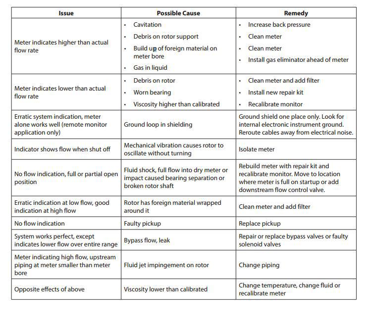
13 Troubleshooting Guide 13
14 14
15 15
16 COMPANY W. Corporate Preserve Dr. #600 Oak Creek, WI AW-Lake Company. All rights reserved. Doc ID:SANITARYMAN16
TR-QS Wafer-Style Turbine Flow Meters Installation, Operating & Maintenance Manual
 COMPANY TR-QS Wafer-Style Turbine Flow Meters Installation, Operating & Maintenance Manual 2016 AW-Lake Company. All rights reserved. Doc ID:TRQSMAN16 Table of Contents Contents Table of Contents... 2
MODEL 1100 TURBINE FLOW METER
 MODEL 1100 TURBINE FLOW METER INSTALLATION & INSTRUCTION MANUAL 8635 Washington Ave. Racine, Wisconsin 53406 Phone: 800.433.5263 Fax: 800.245.3569 www.hedland.com 2 OPERATIONAL START-UP Fluid entering
Model 1100 Turbine Flow Meter
 Model 1100 Turbine Flow Meter INSTALLATION & INSTRUCTION MANUAL 8635 Washington Avenue Racine, Wisconsin 53406 Tel: 800-433-5263 or 262-639-6770 Fax: 800-245-3569 or 262-639-2267 www.hedland.com TABLE
MODEL 1100 TURBINE METER REPAIR KITS
 MODEL 1100 TURBINE METER REPAIR KITS REPAIR MANUAL Rev. B 52 NW 42 nd Street Oklahoma City, OK 73118 Phone: (405) 525-6601 Kimray.com GENERAL DESCRIPTION The Kimray Model 1100 turbine flow meter is designed
Turbine Flow Meter Series Turbine Meter USER MANUAL
 Turbine Flow Meter 1100 Series Turbine Meter USER MANUAL Turbine Flow Meters, 1100 Series CONTENTS Introduction......................................................................... 3 Operating Principle....................................................................
Turbine Flow Meter. B16N Series FloClean Tri-Clover End Fitting. User Manual. TRB-UM EN-01 (December 2016)
") Turbine Flow Meter B16N Series FloClean Tri-Clover End Fitting TRB-UM-02253-EN-01 () User Manual Turbine Flow Meter, B16N Series FloClean Tri-Clover End Fitting CONTENTS Scope of This Manual 3 Unpacking
Turbine Flow Meter B16N Series FloClean Tri-Clover End Fitting TRB-UM-02253-EN-01 () User Manual Turbine Flow Meter, B16N Series FloClean Tri-Clover End Fitting CONTENTS Scope of This Manual 3 Unpacking
MODEL 200 MULTI-JET FLOW METER
 MODEL 200 MULTI-JET FLOW METER - For Water Applications - INSTALLATION & INSTRUCTION MANUAL 8635 Washington Avenue Racine, Wisconsin 53406 Toll Free: 800.235.1638 Phone: 262.639.6770 Fax: 262.417.1155
MODEL 900 IMPELLER-TYPE FLOW METER
 MODEL 900 IMPELLER-TYPE FLOW METER - For Water Applications - INSTALLATION & INSTRUCTION MANUAL 8635 Washington Avenue Racine, Wisconsin 53406 Toll Free: 800.235.1638 Phone: 262.639.6770 Fax: 262.417.1155
Model 1100 Turbine Flow Meter
 Model 1100 Turbine Flow Meter INSTALLATION & INSTRUCTION MANUAL 8635 Washington Avenue Racine, Wisconsin 53406 Toll Free: 800.235.1638 Phone: 262.639.6770 Fax: 262.417.1155 www.blancett.com TABLE OF CONTENTS
MODEL 200 MULTI-JET FLOW METER
 MODEL 200 MULTI-JET FLOW METER - For Water Applications - INSTALLATION & INSTRUCTION MANUAL 8635 Washington Avenue Racine, Wisconsin 53406 Technical Toll-Free: 877.722.4631 Sales Toll-Free: 800.235.1638
Paddle Wheel Turbine Flow Meters Installation, Operating & Maintenance Manual
 COMPANY Paddle Wheel Turbine Flow Meters Installation, Operating & Maintenance Manual 2016 AW-Lake Company. All rights reserved. Doc ID:PADDLEMAN082416 Mechanical Specifications Flow Meter with Polypropylene
Model 1100 Turbine Flow Meter Repair Kits
 Model 1100 Turbine Flow Meter Repair Kits INSTALLATION & INSTRUCTION MANUAL 8635 Washington Avenue Racine, Wisconsin 53406 Toll Free: 800.235.1638 Phone: 262.639.6770 Fax: 262.417.1155 www.blancett.com
RUN ACCUM. TOTAL STOP BAT LOW HIGH
 TURBOPULSE TURBINE FLOWMETER INSTRUCTION MANUAL gal RUN ACCUM. TOTAL STOP BAT LOW HIGH RESET > PROGRAM ENTER ACCUM TOTAL ^ RATE TOTAL TP050 TABLE OF CONTENTS 1. INTRODUCTION Overview 1 1.1 Model number
Turbine Flow Meter. Model User Manual. TRB-UM EN-03 (December 2015)
") Turbine Flow Meter Model 1200 TRB-UM-00290-EN-03 () User Manual Turbine Flow Meter, Model 1200 CONTENTS Scope of This Manual 3 Unpacking and Inspection 3 Safety 3 Terminology and Symbols 3 Considerations
Turbine Flow Meter Model 1200 TRB-UM-00290-EN-03 () User Manual Turbine Flow Meter, Model 1200 CONTENTS Scope of This Manual 3 Unpacking and Inspection 3 Safety 3 Terminology and Symbols 3 Considerations
COMPANY. Pneumatic Flow Meters Installation, Operating & Maintenance Manual AW-Lake Company. All rights reserved. Doc ID:PNEUMAN082516
 COMPANY Pneumatic Flow Meters Installation, Operating & Maintenance Manual 2016 AW-Lake Company. All rights reserved. Doc ID:PNEUMAN082516 Technical Specifications Measuring Accuracy ±2.5% of full scale
Liquid Turbine Flowmeter
 NUFLO Liquid Turbine Flowmeter User Manual 167018 Explosion-proof for use in Class I, Division I, Groups A, B, C, D Hazardous Environments ANSI 12.27.01-2003 Single Seal Part No. 9A-100062201, Rev. 01
Product Data Sheet. Turbine Flow Meter. B16D Series FloClean Sanitary DESCRIPTION INSTALLATION REPAIR KITS
 DESCRIPTION Turbine Flow Meter The FloClean Sanitary turbine flow meter was developed for use in the food, beverage and pharmaceutical industries. The 36L stainless steel construction provides a durable
Paddle Wheel Turbine Flow Meters Installation, Operating & Maintenance Manual
 COMPANY Paddle Wheel Turbine Flow Meters Installation, Operating & Maintenance Manual Mechanical Specifications Flow Meter with Polypropylene Body (ES version) Maximum Operating Pressure: 150 PSIG Maximum
Model 200 Multi-Jet Flow Meter. 02-PDM-UM (July 2012) Installation & Operation Manual
 Installation & Operation Manual") Model 200 Multi-Jet Flow Meter 02-PDM-UM-00109 (July 2012) Installation & Operation Manual TABLE OF CONTENTS Introduction...3 Operating Principle...3 Specifications...4 Operating Limitations...5 Installation
Model 200 Multi-Jet Flow Meter 02-PDM-UM-00109 (July 2012) Installation & Operation Manual TABLE OF CONTENTS Introduction...3 Operating Principle...3 Specifications...4 Operating Limitations...5 Installation
EZ-IN Series Turbine Flowmeter
 Class I, Group A, B, C, D, Division I Complies with ASME Standard B31.3 NUFLO EZ-IN Series Turbine Flowmeter Installation Manual Part No. 9A-100062997, Rev. 01 Measurement Systems EZ-IN Series BF Turbine
C-LB45-A FUEL METER ASSEMBLY INSTALLATION & OPERATION MANUAL
 C-LB45-A FUEL METER ASSEMBLY INSTALLATION & OPERATION MANUAL Version.4 Instrumart 35 GREEN MOUNTAIN DR S. BURLINGTON VERMONT 543 USA 888-FLOW-888 www.instrumart.com/tactical-meters CONTENTS. Index of Figures....
Turbine Flow Meter. User Manual. Top Load 1 in. and 2 in. Meters. TRB-UM EN-01 (September 2018)
") Turbine Flow Meter Top Load 1 in. and 2 in. Meters TRB-UM-02597-EN-01 () User Manual Turbine Flow Meter, Top Load 1 in. and 2 in. Meters CONTENTS Unpacking and Inspection.........................................
Turbine Flow Meter Top Load 1 in. and 2 in. Meters TRB-UM-02597-EN-01 () User Manual Turbine Flow Meter, Top Load 1 in. and 2 in. Meters CONTENTS Unpacking and Inspection.........................................
COMPANY. Liquid Flow Meters Installation, Operating & Maintenance Manual AW-Lake Company. All rights reserved. Doc ID:FLOWLIQUIDMETERMAN082516
 COMPANY Liquid Flow Meters Installation, Operating & Maintenance Manual 2016 AW-Lake Company. All rights reserved. Doc ID:FLOWLIQUIDMETERMAN082516 Technical Specifications Measuring Accuracy ±2.0% of full
TX 115/215 Hot-tap Insertion Turbine Instructions
 TX 115/215 Hot-tap Insertion Turbine Instructions General Information These hot tap versions of the proven TX insertion flow sensors are designed to install or be serviced without depressurizing the pipe.
ZTM AND ZTMB ZENNER TURBINE METERS INSTALLATION, MAINTENANCE AND SERVICING
 ZTM AND ZTMB ZENNER TURBINE METERS INSTALLATION, MAINTENANCE AND SERVICING INSTALLATION 1. The meter is intended for measuring potable, cold water in one direction. 2. The meter is to be installed in a
Product Data Sheet. Turbine Flow Meter. QuikSert DESCRIPTION INSTALLATION FEATURES REPAIR KITS
 DESCRIPTION Turbine Flow Meter QuikSert The QuikSert in-line turbine flow meter was developed for liquid applications where accuracy and dependability are needed. QuikSert s stainless steel body incorporates
Industrial Turbo Meters, Sizes 2" through 6"
 Industrial Turbo Meters Sizes 2" through 6" TUR-UM-00530-EN-19 (October 2014) User Manual Industrial Turbo Meters, Sizes 2" through 6" User Manual CONTENTS Scope of the Manual 5 Specifications 5 Product
Sanitary Sensors. High Quality, Precision. Sanitary Sensors. THORNTON Leading Pure Water Analytics
 THORNTON Leading Pure Water Analytics Sanitary Sensors Sanitary Sensors Temperature Sensors 3A Sanitary Turbine Flow Sensors Pressure Sensors Tank Level Sensors High Quality, Precision Sanitary Sensors
TX101/201 Insertion Turbine Instructions
 TX101/201 Insertion Turbine Instructions General Information Sapphire bearings and a non-drag pick-off give these adjustable insertion turbine flow sensors a wide flow and long life. A Hall-effect device
TX115/215 Hot-tap Insertion Turbine Instructions
 TX115/215 Hot-tap Insertion Turbine Instructions General Information These hot tap versions of the proven TX insertion flow sensors are designed to install or be serviced without depressurizing the pipe.
INSTALLATION AND OPERATION
 Industrial Type Turbine Flowmeter NT Hygienic Type Turbine Flowmeter BNO Low Flow Pelton Wheel Flowmeter NS INSTALLATION AND OPERATION Nixon Flowmeters Ltd. Leckhampton, Cheltenham, Glos UK Tel. 0044 (0)
TX101/201 Insertion Turbine Instructions
 TX101/201 Insertion Turbine Instructions General Information Ruby bearings and a non-drag pick-off give these adjustable insertion turbine flow sensors a wide flow and long life. A sensor detects the passage
OVAL GEAR FLOWMETER MECHANICAL MODEL 012 (½ )
") INST-012M_R4 11/2012 OVAL GEAR FLOWMETER MECHANICAL MODEL 012 (½ ) INSTRUCTION MANUAL To the Owner PLEASE READ THIS SAFTEY INFORMATION CAREFULLY BEFORE USE. Read and retain this instruction manual to assist
INST-012M_R4 11/2012 OVAL GEAR FLOWMETER MECHANICAL MODEL 012 (½ ) INSTRUCTION MANUAL To the Owner PLEASE READ THIS SAFTEY INFORMATION CAREFULLY BEFORE USE. Read and retain this instruction manual to assist
IMPORTANT!!!! Read this manual before attempting any installation, wiring or operation.
 Industrial Turbo Meters Sizes 2" through 6" Installation & Operation Manual IMPORTANT!!!! Read this manual before attempting any installation, wiring or operation. BadgerMeter,Inc. IOM-003-15 Part No.
TABLE OF CONTENTS GENERAL INFORMATION
 To the owner Congratulations on receiving your GPI Industrial Grade Turbine. We are pleased to provide you with a product designed to give you maximum reliability and efficiency. Our business is the design,
NJK Precision Product NJK-02 Sensor Installation Guide
 Precision -02 Sensor 2017 Product Line Precision Product Table of Contents Precision Company Overview - Page 2-02 Installation Guidelines - Page 3-02 Recommended Installations - Page 5-02 Non-Recommended
BI-DIRECTIONAL INSERTION FLOW TRANSDUCER
 DUALPULSE BI-DIRECTIONAL INSERTION FLOW TRANSDUCER INSTRUCTION MANUAL DUALPULSE LOCK 1.1 General arrangement Thank you for purchasing a Dualpulse Flowmeter. It is important that you read this manual to
A1 Commercial Grade Meters
 A1 Commercial Grade Meters Commercial Grade Meters are designed as self-contained, battery powered units. These indicating meters come in Aluminum or Nylon only. A1 Meters are not field serviceable like
OVAL GEAR FLOWMETER ELECTRONIC MODEL 019 / ¾
 INST-019P_R4 11/2012 OVAL GEAR FLOWMETER ELECTRONIC MODEL 019 / ¾ INSTRUCTION MANUAL To the Owner PLEASE READ THIS SAFTEY INFORMATION CAREFULLY BEFORE USE. Read and retain this instruction manual to assist
FIXED DEPTH INSERTION METER INSTRUCTIONS
 UNPACKING Please open and inspect your package upon receipt. Your package was packed with great care and all the necessary packing materials to arrive to you undamaged. If you do find an item that is broken
SES. Stainless Single-Jet Meter Instructions PROUDLY MADE IN THE USA
 SES Stainless Single-Jet Meter Instructions PROUDLY MADE IN THE USA ISO 9001:2008 Certified Company TABLE OF CONTENTS General Information General Information...Page 3 Features...Page 3 Specifications...Page
OVAL GEAR FLOWMETER MECHANICAL MODEL 075 (3 )
") INST-075M_R4 11/2012 OVAL GEAR FLOWMETER MECHANICAL MODEL 075 (3 ) INSTRUCTION MANUAL To the Owner PLEASE READ THIS SAFTEY INFORMATION CAREFULLY BEFORE USE. Read and retain this instruction manual to assist
INST-075M_R4 11/2012 OVAL GEAR FLOWMETER MECHANICAL MODEL 075 (3 ) INSTRUCTION MANUAL To the Owner PLEASE READ THIS SAFTEY INFORMATION CAREFULLY BEFORE USE. Read and retain this instruction manual to assist
Insertion turbine INSTRUCTION SHEET. TECHNICAL PRODUCT
 TECHNICAL PRODUCT INSTRUCTION SHEET Insertion turbine OVERVIEW These insertion flow transducers provide a cost effective and simple means of measuring the flow of a wide range of low viscosity liquids.
COMPANY. Flow Rate Alarms Installation, Operating & Maintenance Manual
 COMPANY Flow Rate Alarms Installation, Operating & Maintenance Manual 2017 AW-Lake Company. All rights reserved. Doc ID:FLOWALARMMA V1 2017 Technical Specifications Measuring Accuracy ±2.0% of full scale
SERIES TBS INSERTION TURBINE TBS-0XX TBS-1XX
 F- SERIES INSERTION TURBINE instructions -0XX -1XX Table of Contents GENERAL INFORMATION General Information Features, Specifications... Page 1 Installation Piping, Immersion, Positioning the Meter...
IP80-Series FLOW SENSOR INSTRUCTIONS IP81 IP :2008 ISO CERTIFIED COMPANY IP80-SERIES FLOW SENSOR INSTRUCTIONS
 IP80-SERIES FLOW SENSOR INSTRUCTIONS IP80-Series FLOW SENSOR INSTRUCTIONS IP81 IP82 9 001:2008 ISO CERTIFIED COMPANY TABLE OF CONTENTS General Information Features, Specifications...Page 3 Installation
OVAL GEAR FLOWMETER MECHANICAL MODEL 012 (½ )
") 012 Mech 07.11 OVAL GEAR FLOWMETER MECHANICAL MODEL 012 (½ ) INSTRUCTION MANUAL To the Owner PLEASE READ THIS SAFTEY INFORMATION CAREFULLY BEFORE USE. Read and retain this instruction manual to assist
012 Mech 07.11 OVAL GEAR FLOWMETER MECHANICAL MODEL 012 (½ ) INSTRUCTION MANUAL To the Owner PLEASE READ THIS SAFTEY INFORMATION CAREFULLY BEFORE USE. Read and retain this instruction manual to assist
TECHNICAL SPECIFICATIONS. Measuring Accuracy ±2% of full scale. Repeatability ±0.5% of full scale
 TECHNICAL SPECIFICATIONS Measuring Accuracy ±2% of full scale Repeatability ±0.5% of full scale Flow Measuring Range 1/2 porting: 0.5 15 GPM (2 60 LPM) 3/4 1 porting: 1.5 50 GPM (60 200 LPM) Turn Down
OWNER S MANUAL Model: TR-40-EX ( ) (40 Gallon Lawn & Garden Trailer Sprayer w/5-nozzle Boom Assembly)
 (40 Gallon Lawn & Garden Trailer Sprayer w/5-nozzle Boom Assembly)") OWNER S MANUAL Model: TR-40-EX (5301338) (40 Gallon Lawn & Garden Trailer Sprayer w/5-nozzle Boom Assembly) Technical Specifications 40 Gal. Corrosion-Resistant Polyethylene Tank 12 Volt Diaphragm Pump,
OWNER S MANUAL Model: TR-40-EX (5301338) (40 Gallon Lawn & Garden Trailer Sprayer w/5-nozzle Boom Assembly) Technical Specifications 40 Gal. Corrosion-Resistant Polyethylene Tank 12 Volt Diaphragm Pump,
HM860 FLOWMETER OPERATOR S MANUAL DO NOT USE OR OPERATE THIS EQUIPMENT UNTIL THIS MANUAL HAS BEEN READ AND THOROUGHLY UNDERSTOOD
 HM860 FLOWMETER OPERATOR S MANUAL DO NOT USE OR OPERATE THIS EQUIPMENT UNTIL THIS MANUAL HAS BEEN READ AND THOROUGHLY UNDERSTOOD PART NUMBER 393-008-020 Rev. C Table of Contents TABLE OF CONTENTS 393-008-020
Oil Control Handle with Mechanical Meter. Introduction. General Information. Important Information 3575-A 3575-B 3575-C 3575-D
 Introduction Thank you for purchasing an Alemite 3575 series Control Handle complete with mechanical meter. It has been designed to accurately dispense, measure and control flow of engine oil, gear oil,
Positive Displacement Flowmeters GM020 series instruction manual
 ACCURATE FLOWMETERS & INSTRUMENTATION PVT. LTD. Positive Displacement Flowmeters GM020 series instruction manual GM020 Pulse Meter From serial No. CXXXX Accurate Flowmeters & Instrumentation Pvt. Ltd.
GPM Hydraulic Flow Meter User Manual
 4278 100 GPM Hydraulic Flow Meter User Manual Introduction The OTC 4278 Hydraulic Flow Meter has been designed for easy connection to a hydraulic circuit so that flow, pressure and temperature can be readily
IP800-Series FLOW SENSOR INSTRUCTIONS IP810 IP :2008 ISO CERTIFIED COMPANY IP800-SERIES FLOW SENSOR INSTRUCTIONS
 -SERIES FLOW SENSOR INSTRUCTIONS -Series FLOW SENSOR INSTRUCTIONS IP810 IP820 9001:2008 ISO CERTIFIED COMPANY TABLE OF CONTENTS General Information Features, Specifications...Page 3 Installation Insertion
WARCO CHEMAG SERIES GH FILTERS
 WARCO CHEMAG SERIES GH FILTERS High Performance Pleated & Bag Type Filtration Systems INSTALLATION, OPERATION, AND MAINTENANCE INSTRUCTIONS Thank you for your purchase of a WARCO Series GH Filtration System.
IP800-Series FLOW SENSOR INSTRUCTIONS IP810 IP :2008 ISO CERTIFIED COMPANY IP80-SERIES FLOW SENSOR INSTRUCTIONS
 IP80-SERIES FLOW SENSOR INSTRUCTIONS IP800-Series FLOW SENSOR INSTRUCTIONS IP810 IP820 9001:2008 ISO CERTIFIED COMPANY TABLE OF CONTENTS General Information Features, Specifications...Page 3 Installation
Condensed Version of Operator s Manual For The VL600 Series Flowmeters
 Condensed Version of Operator s Manual For The VL600 Series Flowmeters Warranty Agreement JTEC Associates warrants this product to be in good working order for a period of twelve (12) months from installation.
800SVRM-7 5/04 RATE-OF-FLOW CONTROL 800 SERIES CONTROL VALVES
 RATE-OF-FLOW CONTROL RATE-OF-FLOW WITH SOLENOID & EXTERNAL FILTER.2 .3 RATE-OF-FLOW & PRESSURE REDUCIN G WITH SOLENOID & EXTERNAL FI LTER.4 RATE-OF-FLOW & PRESSURE SUSTAINING WITH EXTERNAL FILTER.5 RATE-OF-FLOW
IP800-Series. Insertion Paddlewheel Flow Sensor Instructions PROUDLY MADE IN THE USA
 IP800-Series Insertion Paddlewheel Flow Sensor Instructions PROUDLY MADE IN THE USA ISO 9001:2008 Certified Company TABLE OF CONTENTS General Information General Information...Page 3 Features...Page 3
Liquid Turbine Flow Meter OwnerÊs Manual
 Liquid Turbine Flow Meter OwnerÊs Manual Manual LWGY-G Rev.1.0 Content 1.0 GENERAL INFORMATION... 1 2.0 SPECIFICATIONS... 2 3.0 OPERATION CONDITIONS... 3 4.0 CAUTIONS FOR INSTALLATION... 4 5.0 DIMENSION...
Liquid Turbine Flowmeters
 NUFLO Liquid Turbine Flowmeters Accurate Flow Measurement In 1957, this flowmeter was developed with a tungsten-carbide shaft and bearing to withstand the rugged conditions of the oil field. Over the years,
Flow Sensors & Instruments
 STAINESS STEE TURBINE FOWMETERS Serie X IG PRESSURE AND IG TEMPERATURE Principle of Operation The x range of Turbine Flowmeters meet the demand of most liquid measurement applications. They basically consist
G2 Industrial Grade Meters
 G2 Industrial Grade Meters The unique modular approach of the Industrial Grade Meter line allows you to section 2: g2 industrial grade meters design a meter to match your specific application. Turbine
OWNER S MANUAL. Model: LG-30-TRL ( ) (30 Gallon Lawn & Garden Trailer Sprayer)
 (30 Gallon Lawn & Garden Trailer Sprayer)") OWNER S MANUAL Model: LG-30-TRL (5302317) (30 Gallon Lawn & Garden Trailer Sprayer) Technical Specifications 30 Gal. Corrosion-Resistant Polyethylene Tank 12 Volt Diaphragm Pump, 2.1 g.p.m. 60 psi 15 Ft.
OWNER S MANUAL Model: LG-30-TRL (5302317) (30 Gallon Lawn & Garden Trailer Sprayer) Technical Specifications 30 Gal. Corrosion-Resistant Polyethylene Tank 12 Volt Diaphragm Pump, 2.1 g.p.m. 60 psi 15 Ft.
INSTRUCTION MANUAL AND PARTS LIST FOR 3E CANNED MOTOR PUMPS
 TM INSTRUCTION MANUAL AND PARTS LIST FOR 3E CANNED MOTOR PUMPS WARNING This Special Instruction Manual and General Instructions Manual, CA-1, should be read thoroughly prior to pump installation, operation
IP800-Series. Insertion Paddlewheel Flow Sensor Instructions PROUDLY MADE IN THE USA
 IP800-Series Insertion Paddlewheel Flow Sensor Instructions PROUDLY MADE IN THE USA ISO 9001:2008 Certified Company TABLE OF CONTENTS General Information General Information...Page 3 Features...Page 3
Analog Hydraulic Testers
 Webtec Products Limited Analog Hydraulic Testers www.webtec.co.uk Analog Hydraulic Testers Operating Manual Introduction HT Series Portable Hydraulic Testers have been designed for easy connection to a
FLOW MEASUREMENT TECHNOLOGY FOR POWER AND ENERGY
 COMPANY FLOW MEASUREMENT TECHNOLOGY FOR POWER AND ENERGY ABOUT AW-LAKE COMPANY AW-Lake Company was founded in 1984 as a manufacturer of flow meters and flow monitoring equipment, servicing industrial paint
Positive Displacement Flowmeters GM007 series instruction manual
 MS499G 0603 0003 Positive Displacement Flowmeters GM007 series instruction manual GM007 Pulse Meter From serial No. CXXXX To the owner Thank you for purchasing a GPI GM GPI by telephone or fax.] Series
TX80-Series FLOW SENSOR INSTRUCTIONS TX81 TX :2008 ISO CERTIFIED COMPANY TX80-SERIES FLOW SENSOR INSTRUCTIONS
 TX80-SERIES FLOW SENSOR INSTRUCTIONS TX80-Series FLOW SENSOR INSTRUCTIONS TX81 TX82 9 001:2008 ISO CERTIFIED COMPANY TABLE OF CONTENTS General Information Specifications, Features...Page 1 Installation
Flow Meters. Installation, Operation & Maintenance Manual.
 Flow Meters Installation, Operation & Maintenance Manual www.lakemonitors.com This manual is a service guide produced by the manufacturer and provides specific procedures and/or illustrations for disassembly,
BI-DIRECTIONAL INSERTION METER
 BI-DIRECTIONAL INSERTION METER INSTRUCTION MANUAL LOCK 1 Contents CONTENTS PAGE 1.0 INTRODUCTION 1.1 General arrangement 2 1.2 Overview 3 1.3 Operating principal 3 1.4 Specifications 3 2.0 INSTALLATION
S-Series. Low Flow Meter Instructions SPX SPT. Precision Flow Measurement An ONICON Brand PROUDLY MADE IN THE USA
 S-Series Low Flow Meter Instructions Precision Flow Measurement An ONICON Brand PROUDLY MADE IN THE USA ISO 9001:2008 Certified Company TABLE OF CONTENTS General Information General Information...Page
Instruction Manual HMP TURBINE FLOWMETER. Anderson Instrument Co. Inc. 156 Auriesville Road Fultonville, NY Fax
 Instruction Manual Anderson Instrument Co. Inc. 156 Auriesville Road Fultonville, NY 12072 1-800-833-0081 Fax 518-922-8997 www.anderson-negele.com Instrument Model Number Instrument Serial Number HMP TURBINE
CIRCLE SEAL CONTROLS
 CIRCLE SEAL CONTROLS ATKOMATIC SOLENOID VALVES INSTALLATION, MAINTENANCE, AND OPERATION INSTRUCTIONS 3000 SERIES Bronze, Normally Closed, Direct Lift Installation Instructions WARNING: These instructions
POSITIVE DISPLACEMENT FLOWMETERS
 MS345BR 0408 0001 POSITIVE DISPLACEMENT FLOWMETERS M4 BRONZE SERIES INSTRUCTION MANUAL M4 Pulse; M4 Standard LCD; M4 Deluxe LCD; From serial No.CXXXX TO THE OWNER Please take a few minutes to read through
FUNDAMENTALS OF INSERTION TURBINE METERS Les Bottoms Thermo Electron Corporation, Flow Systems
 FUNDAMENTALS OF INSERTION TURBINE METERS Les Bottoms Thermo Electron Corporation, Flow Systems 9303 W. Sam Houston Parkway, Houston, TX 77099 INTRODUCTION The insertion turbine meter is well suited for
IOM IR-910M0-X. Hydrometer Magnetic Drive with solenoid control
 IOM IR-910M0-X Hydrometer Magnetic Drive with solenoid control (Sizes 1.5''- 4"; DN40-100) Description: The BERMAD Hydrometer with Solenoid Control integrates a Vertical turbine Woltman-type water meter
Hoffer Engineering Guide for Liquids
 Hoffer Engineering Guide for Liquids Accurate, Versatile, Economical... www.hofferflow.com Principle of Operation: Hoffer inline turbine flowmeters are velocity measuring devices, which is to say they
Transmitters. Differential Pressure Transmitters Pneumatic Design FOXBORO 13A D/P Cell
 Transmitters Differential Pressure Transmitters Pneumatic Design FOXBORO 13A D/P Cell Oldest design, developed during WW 2. Can be used for flow, level, and pressure, vent low side. Several ranges 0 to
7000 Series Liquid Turbine Meters
 BARTON 7000 Series Liquid Turbine Meters Models 71, 7, & 73 Barton 7000 series turbines are designed for a broad range of precise liquid measurement applications. Based on 35 years of turbine manufacturing,
OVAL GEAR FLOWMETER ELECTRONIC MODEL 006/009 (¼ )
") INST-006/009P_R9 06/2015 OVAL GEAR FLOWMETER ELECTRONIC MODEL 006/009 (¼ ) INSTRUCTION MANUAL F Serial Meters To the Owner PLEASE READ THIS SAFTEY INFORMATION CAREFULLY BEFORE USE. Read and retain this
INST-006/009P_R9 06/2015 OVAL GEAR FLOWMETER ELECTRONIC MODEL 006/009 (¼ ) INSTRUCTION MANUAL F Serial Meters To the Owner PLEASE READ THIS SAFTEY INFORMATION CAREFULLY BEFORE USE. Read and retain this
INSTALLATION & SERVICE INSTRUCTION MANUAL W.A. KATES FLOW CONTROLLERS FC VALVE MODELS E THRU M
 INSTALLATION & SERVICE INSTRUCTION MANUAL W.A. KATES FLOW CONTROLLERS FC VALVE MODELS E THRU M IMPORTANT 1. W. A. Kates flow rate controllers are designed to accurately regulate flows and are precision
OVAL GEAR Medium capacity positive displacement Mechanical flowmeters. Model: ½ (15m m)
") OVAL GEAR Medium capacity positive displacement Mechanical flowmeters INSTRUCTION MANUAL Model: ½ (15m m) Index / contents 1 1.0 General Page 1.1 Overview 2 1.2 Operating principal 3 1.3 Specifications
OVAL GEAR Medium capacity positive displacement Mechanical flowmeters INSTRUCTION MANUAL Model: ½ (15m m) Index / contents 1 1.0 General Page 1.1 Overview 2 1.2 Operating principal 3 1.3 Specifications
ACHL Series Pump. Operation and Maintenance Manual Air Driven, Hand Operated High Pressure Liquid Pump
 ACHL Series Pump Operation and Maintenance Manual Air Driven, Hand Operated High Pressure Liquid Pump Catalog: 02-9245ME February 2013 Model # Serial # Drawing # Order # Mfg. Date Table of Contents page
Positive Displacement Flowmeters GM020 series instruction manual
 MS244G 0603 0003 Positive Displacement Flowmeters GM020 series instruction manual GM020 Pulse Meter From serial No. CXXXX To the owner Thank you for purchasing a GPI GM Series Flow Meter. Please take a
OWNER S MANUAL. Model: FSUTL60-12V ( ) Technical Specifications. Assembly Instructions
 Technical Specifications. Assembly Instructions") OWNER S MANUAL Model: FSUTL60-12V (5301421) (60 Gallon Lawn & Garden Utility Sprayer - Boom-Ready) Technical Specifications 60 Gal. Corrosion-Resistant Polyethylene Tank Deluxe Pistol-Grip Handgun 25 Ft.
OWNER S MANUAL Model: FSUTL60-12V (5301421) (60 Gallon Lawn & Garden Utility Sprayer - Boom-Ready) Technical Specifications 60 Gal. Corrosion-Resistant Polyethylene Tank Deluxe Pistol-Grip Handgun 25 Ft.
OWNER S MANUAL. Model: FSUTL40-12V ( ) Technical Specifications. Assembly Instructions
 Technical Specifications. Assembly Instructions") OWNER S MANUAL Model: FSUTL40-12V (5301420) (60 Gallon Lawn & Garden Utility Sprayer - Boom-Ready) Technical Specifications 40 Gal. Corrosion-Resistant Polyethylene Tank Deluxe Pistol-Grip Handgun 25 Ft.
OWNER S MANUAL Model: FSUTL40-12V (5301420) (60 Gallon Lawn & Garden Utility Sprayer - Boom-Ready) Technical Specifications 40 Gal. Corrosion-Resistant Polyethylene Tank Deluxe Pistol-Grip Handgun 25 Ft.
A1 SERIES COMMERCIAL GRADE METERS A1 SERIES COMMERCIAL GRADE METERS
 COMMERCIAL GRADE METERS Look for the silver label! Look for the silver label! COMMERCIAL GRADE METERS Commercial Grade Meters are designed as self-contained, battery powered units. These indicating meters
SERVICE KITS REBUILD KIT DESCRIPTION CHART MODEL DESCRIPTION CHART SPECIFICATIONS X X 1 - B X - X X X - B
 OPERATOR S MANUAL INCLUDING: SERVICE KITS, TROUBLESHOOTING, PARTS LIST, DISASSEMBLY & REASSEMBLY. HIGH PRESSURE MATERIAL REGULATOR 65178X-XXX-B RELEASED: 2-12-93 REVISED: 1-11-08 (REV. F) READ THIS MANUAL
flow measurement solutions RIM10 series rotor insertion flowmeters
 flow measurement solutions RIM10 series rotor insertion flowmeters R I M 1 0 RIM10 series rotor insertion flowmeters Versatile enough for almost any challenge Spirax Sarco s RIM10 rotor insertion flowmeters
Series 44 Installation Instructions
 and field service checklist Series 44 Installation Instructions Table of Contents Page 1 Page 2 & 3 Page 4 Page 5 Page 6 Page 7 Page 8 System Components Amplifiers System Components Introduction and Dimensions
TX100/200-SERIES INSERTION TURBINE INSTRUCTIONS TX101/201 TX115/215 ISO 9001:2008 CERTIFIED COMPANY
 TX100/200-SERIES INSERTION TURBINE INSTRUCTIONS TX100/200-SERIES INSERTION TURBINE INSTRUCTIONS TX101/201 TX115/215 ISO 9001:2008 CERTIFIED COMPANY TABLE OF CONTENTS General Information Features, Specifications...Page
Operating Instructions for Oval Wheel Flowmeter. Model: DOC
 Operating Instructions for Oval Wheel Flowmeter Model: DOC We don t accept warranty and liability claims neither upon this publication nor in case of improper treatment of the described products. The document
Liquid Turbine Flowmeters
 NuFlo Liquid Turbine Flowmeters Accurate Flow Measurement NuFlo developed its first flowmeter for oilfield applications in 1957. The meter incorporated a tungsten-carbide shaft and bearing to withstand
M SERIES Multi-Jet Cold Water Meter
 M SERIES Multi-Jet Cold Water Meter /4 1 1-1/2" 2" Maximum Flow GPM 0 0 1 Minimum Flow GPM.2.7 1. 2.0 Maximum Operating Pressure 0 psi Maximum Operating Temperature F ( C) Also Available in Hot Water Applications
OWNER S MANUAL. Model: TR-40-GAS ( ) (40 Gallon Lawn & Garden Trailer Sprayer w/5-nozzle Boom Assembly) Technical Specifications
 (40 Gallon Lawn & Garden Trailer Sprayer w/5-nozzle Boom Assembly) Technical Specifications") OWNER S MANUAL Model: TR-40-GAS (5301339) (40 Gallon Lawn & Garden Trailer Sprayer w/5-nozzle Boom Assembly) Technical Specifications 40 Gal. Corrosion-Resistant Polyethylene Tank 5.5 HP Briggs & Stratton
OWNER S MANUAL Model: TR-40-GAS (5301339) (40 Gallon Lawn & Garden Trailer Sprayer w/5-nozzle Boom Assembly) Technical Specifications 40 Gal. Corrosion-Resistant Polyethylene Tank 5.5 HP Briggs & Stratton
Liquid Turbine Flow Meters
 NuFlo Liquid Turbine Flow Meters NuFlo developed its first flow meter for oilfield applications in 1957. The meter incorporated a tungstencarbide shaft and bearing to withstand the rugged conditions of
F-4600 INLINE ULTRASONIC FLOW METER Installation and Operation Guide
 F-4600 INLINE ULTRASONIC FLOW METER Installation and Operation Guide 11451 Belcher Road South, Largo, FL 33773 USA Tel +1 (727) 447-6140 Fax +1 (727) 442-5699 1054-7 / 34405 www.onicon.com sales@onicon.com
To ensure proper installation, digital pictures with contact information to before startup.
 Check List for Optimal Filter Performance? There should be no back-pressure on the flush line. A 1 valve should have a 2 waste line, and 2 valve should have a 3 waste line. Do not use rubber hosing or