Operating Instructions for Oval Wheel Flowmeter. Model: DOC
|
|
|
- Shavonne Richards
- 6 years ago
- Views:
Transcription


1 Operating Instructions for Oval Wheel Flowmeter Model: DOC
2 We don t accept warranty and liability claims neither upon this publication nor in case of improper treatment of the described products. The document may contain technical inaccuracies and typographical errors. The content will be revised on a regular basis. These changes will be implemented in later versions. The described products can be improved and changed at any time without prior notice. Copyright All rights reserved. 1. Contents 1. Contents Note Instrument Inspection Regulation Use Operating Principle Installation Procedure Disassembly Reassembly Troubleshooting Guide Technical Information Flowmeter Pulser Board/Sensor Specifications Pulser Wiring Diagram Exploded Diagram Pressure Drop v s Viscosity Order Codes Dimensions Declaration of Conformance...16 Manufactured and sold by: Kobold Messring GmbH Nordring D Hofheim Tel.: +49(0) Fax: +49(0) info.de@kobold.com Internet: page 2 DOC K02/0815
3 2. Note Please read these operating instructions before unpacking and putting the unit into operation. Follow the instructions precisely as described herein. The devices are only to be used, maintained and serviced by persons familiar with these operating instructions and in accordance with local regulations applying to Health & Safety and prevention of accidents. When used in machines, the measuring unit should be used only when the machines fulfil the EC-machine guidelines. as per PED 97/23/EG In acc. with Article 3 Paragraph (3), "Sound Engineering Practice", of the PED 97/23/EC no CE mark. 3. Instrument Inspection Instruments are inspected before shipping and sent out in perfect condition. Should damage to a device be visible, we recommend a thorough inspection of the delivery packaging. In case of damage, please inform your parcel service / forwarding agent immediately, since they are responsible for damages during transit. Scope of delivery: The standard delivery includes: Oval Wheel Flowmeter model: DOC Operating Instructions 4. Regulation Use Any use of the Oval Wheel Flowmeter, model: DOC, which exceeds the manufacturer s specification, may invalidate its warranty. Therefore, any resulting damage is not the responsibility of the manufacturer. The user assumes all risk for such usage. PLEASE READ THIS SAFTEY INFORMATION CAREFULLY BEFORE USE. Read and retain this instruction manual to assist you in the operation and maintenance of this product. If you have any problems with the meter, refer to the maintenance and troubleshooting sections of this manual. DOC K02/0815 page 3

4 This manual contains connection and operating instructions for meters with Pulse outputs. This Flow Meter has incorporated the oval rotor principal into its design. This has proven to be a reliable and highly accurate method of measuring flow. Exceptional repeatability and high accuracy over a wide range of fluid viscosities and flow rates are features of the oval rotor design. With a low pressure drop and high pressure rating oval rotor flow meters are suitable for both gravity and pump (in line) applications. WARNING Before use, confirm the fluid to be used is compatible with the meter. Refer to Industry fluid compatibility charts or consult your local representative for advice. To prevent damage from dirt or foreign matter it is recommended that a Y or Basket type 60 mesh strainer be installed as close as possible to the inlet side of the meter. Contact your local representative for advice. CAUTION When a strainer is installed it should be regularly inspected and cleaned. Failure to keep the strainer clean will dramatically effect flow meter performance. CAUTION To prevent damage caused by air purge slowly fill the meter with fluid. To reduce pressure build up turn off the pump at the end of each day. Maintenance can be carried out to the liquid crystal displays and pulse units without removing or isolating the meter from the line. When maintenance to any other part of the meter is required, the meter must be isolated and the line pressure reduced. The reed switch pulse unit can cause inaccurate rate counts when used with high speed counters. It is advised that a debounce circuit be used. 5. Operating Principle When fluid passes through the meter the rotors turn as shown below. The magnets which are located in the rotors will pass across the pulser circuit board (containing either Reed switches or Hall Effect sensors). A signal is generated which is then sent by the Pulse Circuit Board (PCB) to the relevant LC display or receiving instrument. page 4 DOC K02/0815
. 2) Use thread sealant on all pipe threads.")
5 5.1 Installation Procedure 1) It is recommended that when setting up pipe work for meter installations a bypass line is included in the design. This provides the facility for a meter to be removed for maintenance without interrupting production (see figure). 2) Use thread sealant on all pipe threads. 3) For pump applications ensure pipe work has the appropriate working pressure rating to match the pressure output of the pump. See Meter Specifications section for further details. 4) Install a wire mesh strainer, Y or basket type 200 mesh (74 micron) for DOC-515 and 60 mesh (250 micron) for DOC- 520, as close as possible to the inlet side of the meter. 5) Ensure that the meter is installed so that the flow of the liquid is in the direction of the arrows embossed on the meter body. 6) The meter can be installed in any orientation as long as the meter shafts are in a horizontal plane (Refer to figures to the right for correct installation). The register assembly may be orientated to suit the individual. Note: Incorrect installation can cause premature wear of meter components. 7) Do not over tighten meter connections. Note: Incorrect installation can cause premature wear of meter components. 8) It is important that after initial installation you fill the line slowly, high speed air purge could cause damage to the rotors. 9) Test the system for leaks. 10) Check the strainer for swarf or foreign material, after the first 200 litres check periodically, particularly if the flow rate decreases. 6. Disassembly Ensure that the fluid supply to the meter is disconnected, and the line pressure is released before disassembly, with the exception for repair or maintenance to the LC Display or PCB where there is no necessity to isolate the meter from flow. Refer to the exploded parts diagram on subsequent pages for item numbers. 1) Loosen and remove 4 Phillips head or cap head screws (Item 7), see page 12. 2) Remove the meter cap (Item 5) and O-Ring (Item 4). 3) Remove the rotors (Item 2 & 3), note the position of the rotor with the magnet(s) or grub screws. 4) Clean and inspect all components, replace as necessary, see page 8 for spare parts listing. DOC K02/0815 page 5
6 For DOC-520: Ensure that the fluid supply to the meter is disconnected, and the line pressure is released before disassembly, with the exception for repair or maintenance to the LC Display or PCB where there is no necessity to isolate the meter from flow. Refer to the exploded parts diagram on subsequent pages for item numbers. 1) Pulse Caps Models: Undo the conduit connector, remove pulse cap (item 9) and remove the wires from the pulse terminal board (item 5). 2) Standard LC Display: Mark the display orientation with a marking pen, unscrew the four large screws on top of the LC Display. Carefully separate the LC Display from the plastic housing and disconnect the wires from the pulse terminal block. (Refer to additional LCD instruction manual accompanying these instructions). Remove the mounting adaptor plate and gasket. 3) Loosen the cap head screws (Item 7) that hold down the meter cap (Item 4), remove the screws, washers and lift off the cap. 4) Remove the o-ring (Assembly Item 2) from the o-ring groove in the meter cap (Assembly Item 4). 5) Remove rotors (Item 3). 7. Reassembly 1) Replace the rotors (Item 2 & 3), see below for correct orientation. Rotate the rotors by hand to ensure correct engagement. 2) Fit the O-Ring (Item 4) into the o-ring groove in the meter body (Item 1). 3) Fit the top cap assembly (Item 5). Fit the legend plate (Item 6) into correct orientation. Ensure all the alignment marks are lined up with the mark on the body. 4) Fit and tighten the 4 bolts/screws ( ) to the required torque. 5) Check meter function using low air pressure. 6) Restore the fluid & reconnect the wiring. For DOC-520: 1) Before reassembling check the condition of the rotors (replace if necessary). 2) Check that the smooth side of the rotors (not the plug side) is facing you when inserting the rotors, the smooth side of the rotor is the magnet side. There is no difference between rotor one or rotor two. 3) Replace the rotors (Item 3) onto the shafts at 90 degrees to each other (refer Fig) and check their operation by turning either of the rotors. If the rotors are not in mesh correctly or do not move freely, remove one of the rotors and replace correctly at 90 degrees to the other rotor. 4) Re-check the operation of the rotors. 5) Replace the o-ring (Item 2) into groove in the meter cap; if the o-ring has grown or is damaged in any way replace it with a new part. 6) Replace the meter cap making sure that the locating pin in the body lines up with the hole in the meter cap. page 6 DOC K02/0815
 The replacement of cables and connectors are a reversal of the disassembly procedure, replace conduit fitting if required.")
7 7) Insert the cap head screws (Item 7) and tighten in a diagonal sequence 1, 3, 2, 4, etc. 8) The replacement of cables and connectors are a reversal of the disassembly procedure, replace conduit fitting if required. When replacing the Standard LC Display confirm the orientation marks made on disassembly are aligned then screw the register into place. 9) Test the meter by turning the rotors with a finger or by applying very low air pressure (no more than a good breath) to one end of the meter, before returning the meter to the line. 8. Troubleshooting Guide Problem Cause Remedy a) Foreign matter blocking rotors Fluid will not flow through meter Reduced flow through meter b) Line strainer blocked c) Damaged rotors d) Meter connections over tightened e) Fluid is too viscous a) Strainer is partially blocked b) Fluid is too viscous a) Dismantle meter, clean rotors (strainer must be fitted in line) b) Clean strainer c) Replace rotors (Strainer must be fitted in line) d) Re-adjust connections e) See specifications for maximum viscosity a) Clean strainer b) See specifications for maximum viscosity DOC K02/0815 page 7
 Faulty hall sensor b) Faulty reed switch c) Magnets failed a) Battery not connected properly b) Battery flat c) Faulty wiring connection d) Faulty LC display e) Faulty")
8 Problem Cause Remedy a) Fluid flow rate is too high or too low Meter reading inaccurate Meter not giving a pulse signal LCD register not working b) Fluid is too viscous c) Excess wear caused by incorrect installation a) Faulty hall sensor b) Faulty reed switch c) Magnets failed a) Battery not connected properly b) Battery flat c) Faulty wiring connection d) Faulty LC display e) Faulty connection from LC display a) See specifications for minimum and maximum flow rates b) Bleed air from system c) Check meter body and rotors. Replace as required. Refer to installation instructions. a) Replace PCB Board b) Replace PCB Board c) Replace magnets a) Check battery connections b) Replace battery c) Check wiring for loose or faulty connections d) Replace LC display e) Check wiring connections Note! It has a notch in the body not an alignment dimple. Magnet hole/grub screw side must be facing the meter body. page 8 DOC K02/0815
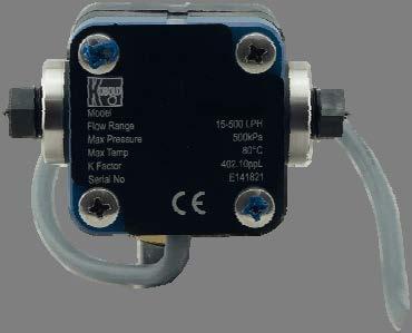
9 9. Technical Information 9.1 Flowmeter Material Body: PPS Oval wheels: PPS Axes (shafts): Hastelloy C Cap: PPS O-rings: FFKM (DOC-515) FEP-O-seal/PTFE encapsulated (DOC-520) Accuracy: ±1% of reading (DOC-515) ±0.5 % of reading (DOC-520) Repeatability: typ. ±0.03% Protection: IP 67 Medium temperature: -40 C C (-40 F F) Max. ambient temp.: +80 C Max. pressure: 5 bar (DOC-515) 10 bar (DOC-520) Electrical connection: DOC-515: 1 m PVC cable DOC-520: cable entry M20x1.5 Recommended Filter DOC-515: DOC-520: <75µm micron (200 mesh) <250µm micron (60 mesh) Output pulse resolution Model Measuring range Pulse/litre DOC-515 below 5 cp: L/h cp: L/h 400 DOC-520 below 5 cp: 8-70 L/m cp: 3-80 L/min Pulser Board/Sensor Specifications There are 2 pulse board options with all KOBOLD pulse flowmeters: Standard Option 1-1 x Reed Switch 1x Hall Effect Output Hazardous Option 2-1 x Reed Switch Output DOC K02/0815 page 9
10 Output signals Standard pulse meter 2 x Digital (Square Wave) Reed Switch 2 Current Maximum 500 ma (Mechanical Sensor) Voltage Maximum 30 VDC Contact rating Maximum 3 10 W Hall Effect 2 Maximum Current 7.5 ma (Electronic Sensor) Operating Voltage 4.5 V to 24 VDC Transistor Type Open-Collector NPN 2 Voltage & current specification apply per sensor (not combined) 3 Contact rating maximum is 10 W. Neither current nor voltage maximum should be exceeded in achieving this. 10. Pulser Wiring Diagram Please read this information carefully before installation Hall Effect: Hall effect sensors require an external pull up resistor to be fitted by the installer for correct operation. Powering a Hall effect sensor without a resistor wired between the supply voltage and the signal line will result in damage to the sensor. * KOBOLD pulser boards are not fitted with a pull up resistor. Reed Switch: In order to protect the reed switch from over current, and to maximise life expectancy, we recommend limiting the current through the switch by fitting a series resistor in between the signal leg and the PLC/signal sensing device. ** KOBOLD pulser boards are not fitted with a current limiting resistor. For 12 VDC we recommend a1 kω resistor. For 24 VDC, we recommend a 1.8 k-2.2 kω resistor. Sensor wiring connections Output type Wire Function Wire Function Wire Function Note Reed/Hall Reed Green Yellow No polarity required Hall Red + VDC Black Gnd (0 V) White Signal NPN Open Collector Reed/Reed Green Yellow No polarity required page 10 DOC K02/0815
11 Hall sensor/reed switch pulse output Reed switch pulse output DOC K02/0815 page 11
12 11. Exploded Diagram DOC-515 Item N o Part Description 1 Meter Body 2 Active Rotor 3 Neutral Rotor 4 O-Ring 5 Meter Cap 6 Legend Plate 7 Meter Cap Screws page 12 DOC K02/0815
13 DOC-520 Item N o Part Description 1 Meter Body 2 O-Ring 3 Rotors 4 Meter Cap 5 Printed Circuit Board 6 PCB Mounting Screws 7 Meter Cap Screws 8 Pulser Cap Gasket 9 Pulser Cap 10 Pulser Cap Screws DOC K02/0815 page 13
14 11.1 Pressure Drop v s Viscosity 12. Order Codes Example: DOC 515HR2H00 Model Material Range Mech. connection R2 = ¼ BSP N2 = ¼ NPT Electronic H0 = Hall sensor/ reed switch pulse output R0* = Reed switch pulse output 15H = L/h DOC- 5 = PPS R6 = 1 BSP 20H = 3-80 L/min N6 = 1 NPT * Should be chosen when using DOC in intrinsically safe circuits as simple apparatus Options 0 = without Y = special option page 14 DOC K02/0815

15 13. Dimensions DOC-515 DOC-520 DOC K02/0815 page 15
16 14. Declaration of Conformance We, KOBOLD Messring GmbH, Hofheim-Ts, Germany, declare under our sole responsibility that the product: Oval Wheel Flowmeter Model: DOC to which this declaration relates is in conformity with the standards noted below: EN :2006 Electromagnetic Compatibility Electrical equipment for measurement, control and laboratory use Also the following EC guidelines are fulfilled: 2004/108/EC 2006/42/EC EMC Directive Machinery Directive Hofheim, 16. Jun H. Peters M. Wenzel General Manager Proxy Holder page 16 DOC K02/0815
OVAL GEAR FLOWMETER ELECTRONIC MODEL 019 / ¾
 INST-019P_R4 11/2012 OVAL GEAR FLOWMETER ELECTRONIC MODEL 019 / ¾ INSTRUCTION MANUAL To the Owner PLEASE READ THIS SAFTEY INFORMATION CAREFULLY BEFORE USE. Read and retain this instruction manual to assist
OVAL GEAR FLOWMETER ELECTRONIC MODEL 006/009 (¼ )
") INST-006/009P_R9 06/2015 OVAL GEAR FLOWMETER ELECTRONIC MODEL 006/009 (¼ ) INSTRUCTION MANUAL F Serial Meters To the Owner PLEASE READ THIS SAFTEY INFORMATION CAREFULLY BEFORE USE. Read and retain this
INST-006/009P_R9 06/2015 OVAL GEAR FLOWMETER ELECTRONIC MODEL 006/009 (¼ ) INSTRUCTION MANUAL F Serial Meters To the Owner PLEASE READ THIS SAFTEY INFORMATION CAREFULLY BEFORE USE. Read and retain this
OVAL GEAR FLOWMETER ELECTRONIC MODEL 025 / 1
 025 Puls 07.11 OVAL GEAR FLOWMETER ELECTRONIC MODEL 025 / 1 INSTRUCTION MANUAL To the Owner PLEASE READ THIS SAFTEY INFORMATION CAREFULLY BEFORE USE. Read and retain this instruction manual to assist you
Positive Displacement Flowmeters GM020 series instruction manual
 ACCURATE FLOWMETERS & INSTRUMENTATION PVT. LTD. Positive Displacement Flowmeters GM020 series instruction manual GM020 Pulse Meter From serial No. CXXXX Accurate Flowmeters & Instrumentation Pvt. Ltd.
OVAL GEAR FLOWMETER ELECTRONIC MODEL 025 / 1. Type CR for Corrosive Applications
 INST-CR025P_R1 012/2011 OVAL GEAR FLOWMETER ELECTRONIC MODEL 025 / 1 Type CR for Corrosive Applications INSTRUCTION MANUAL To the Owner PLEASE READ THIS SAFTEY INFORMATION CAREFULLY BEFORE USE. Read and
OVAL GEAR FLOWMETER ELECTRONIC MODEL 006/009 (¼ )
") 012 Puls 07.11 OVAL GEAR FLOWMETER ELECTRONIC MODEL 006/009 (¼ ) INSTRUCTION MANUAL To the Owner PLEASE READ THIS SAFTEY INFORMATION CAREFULLY BEFORE USE. Read and retain this instruction manual to assist
012 Puls 07.11 OVAL GEAR FLOWMETER ELECTRONIC MODEL 006/009 (¼ ) INSTRUCTION MANUAL To the Owner PLEASE READ THIS SAFTEY INFORMATION CAREFULLY BEFORE USE. Read and retain this instruction manual to assist
Positive Displacement Flowmeters GM007 series instruction manual
 MS499G 0603 0003 Positive Displacement Flowmeters GM007 series instruction manual GM007 Pulse Meter From serial No. CXXXX To the owner Thank you for purchasing a GPI GM GPI by telephone or fax.] Series
POSITIVE DISPLACEMENT FLOWMETERS
 MS345BR 0408 0001 POSITIVE DISPLACEMENT FLOWMETERS M4 BRONZE SERIES INSTRUCTION MANUAL M4 Pulse; M4 Standard LCD; M4 Deluxe LCD; From serial No.CXXXX TO THE OWNER Please take a few minutes to read through
Positive Displacement Flowmeters GM020 series instruction manual
 MS244G 0603 0003 Positive Displacement Flowmeters GM020 series instruction manual GM020 Pulse Meter From serial No. CXXXX To the owner Thank you for purchasing a GPI GM Series Flow Meter. Please take a
OVAL GEAR FLOWMETER MECHANICAL MODEL 012 (½ )
") INST-012M_R4 11/2012 OVAL GEAR FLOWMETER MECHANICAL MODEL 012 (½ ) INSTRUCTION MANUAL To the Owner PLEASE READ THIS SAFTEY INFORMATION CAREFULLY BEFORE USE. Read and retain this instruction manual to assist
INST-012M_R4 11/2012 OVAL GEAR FLOWMETER MECHANICAL MODEL 012 (½ ) INSTRUCTION MANUAL To the Owner PLEASE READ THIS SAFTEY INFORMATION CAREFULLY BEFORE USE. Read and retain this instruction manual to assist
OVAL GEAR FLOWMETER MECHANICAL MODEL 075 (3 )
") INST-075M_R4 11/2012 OVAL GEAR FLOWMETER MECHANICAL MODEL 075 (3 ) INSTRUCTION MANUAL To the Owner PLEASE READ THIS SAFTEY INFORMATION CAREFULLY BEFORE USE. Read and retain this instruction manual to assist
INST-075M_R4 11/2012 OVAL GEAR FLOWMETER MECHANICAL MODEL 075 (3 ) INSTRUCTION MANUAL To the Owner PLEASE READ THIS SAFTEY INFORMATION CAREFULLY BEFORE USE. Read and retain this instruction manual to assist
OVAL GEAR FLOWMETER MECHANICAL MODEL 012 (½ )
") 012 Mech 07.11 OVAL GEAR FLOWMETER MECHANICAL MODEL 012 (½ ) INSTRUCTION MANUAL To the Owner PLEASE READ THIS SAFTEY INFORMATION CAREFULLY BEFORE USE. Read and retain this instruction manual to assist
012 Mech 07.11 OVAL GEAR FLOWMETER MECHANICAL MODEL 012 (½ ) INSTRUCTION MANUAL To the Owner PLEASE READ THIS SAFTEY INFORMATION CAREFULLY BEFORE USE. Read and retain this instruction manual to assist
POSITIVE DISPLACEMENT FLOWMETERS
 MS589 0409 00 POSITIVE DISPLACEMENT FLOWMETERS M80 SERIES INSTRUCTION MANUAL M80 Pulse; Standard LCD; Deluxe LCD; From serial No.CXXXX TO THE OWNER Please take a few minutes to read through this manual
INSTRUCTION MANUAL MN7 series
 Badger Meter Europa GmbH INSTRUCTION MANUAL MN7 series September 2001 Version MN7-09/01-e Content Content Page 1. To the owner 1 2. Important information 1 3. Installation 3 4. Operation 4 5. Electrical
MX06 - MX100 OVAL GEAR FLOWMETER SERIES
 MXL-INST Rev 7 04/2016 MX06 - MX100 OVAL GEAR FLOWMETER SERIES INSTRUCTION MANUAL To the Owner Please read and retain this instruction manual to assist you in the operation and maintenance of this product.
MODEL MX75 3 OVAL GEAR FLOWMETER
 Installation & Maintenance Instructions MODEL MX75 3 OVAL GEAR FLOWMETER Supplied by.com Call us on +44 (0)118 916 9420 Email info@247able.com MXL-INST75 Rev 1 06/2013 MODEL MX75 3 OVAL GEAR FLOWMETER
FPD1001B thru FPD1003B, FPD1102B and FPD1103B, FPD1201B thru FPD1203B SERIES LOW FLOW Positive Displacement Flowmeters
 FPD1001B thru FPD1003B, FPD1102B and FPD1103B, FPD1201B thru FPD1203B SERIES LOW FLOW Positive Displacement Flowmeters To the owner: Please take a few minutes to read through the manual before installing
MODEL MX12 1/2 OVAL GEAR FLOWMETER
 MXL-INST12 Rev 4 12/2013 MODEL MX12 1/2 OVAL GEAR FLOWMETER INSTRUCTION MANUAL To the Owner Please read and retain this instruction manual to assist you in the operation and maintenance of this product.
MX06 - MX100 OVAL GEAR FLOWMETER SERIES APPROVED FOR USE IN HAZARDOUS AREAS
 MXEX-INST Rev 9.0 04/2016 MX06 - MX100 OVAL GEAR FLOWMETER SERIES APPROVED FOR USE IN HAZARDOUS AREAS INSTRUCTION MANUAL To the Owner Page 1 of 33 index Installation Pre-installation checks. Page 3 Operating
Operating Instructions for Paddle Bellows Flow Monitor. Model: FPS-P...
 Operating Instructions for Paddle Bellows Flow Monitor Model: FPS-P... 1. Contents 1. Contents... 2 2. Note... 3 3. Instrument Inspection... 3 4. Regulation Use... 4 5. Operating Principle... 5 6. Mechanical
Operating Instructions for Plastic Flow Meter. Model: KSK
 Operating Instructions for Plastic Flow Meter Model: KSK 1. Contents 1. Contents... 2 2. Note... 3 3. Instrument Inspection... 3 4. Regulation Use... 3 5. Operating Principle... 4 6. Mechanical Connection...
Operating Instructions for Polysulfone Paddle Monitor. Model: PPS-..
 Operating Instructions for Polysulfone Paddle Monitor Model: -.. 1. Contents 1. Contents... 2 2. Note... 3 3. Regulation Use... 3 4. Operating Principle... 3 5. Instrument Inspection... 4 6. Mechanical
The experts in fluid technology
 MS65BR 0302 0001 The experts in fluid technology Positive Displacement Flowmeters M40 Bronze series instruction manual M40 Pulse M40 Standard LCD M40 Deluxe LCD From serial No. CXXXX To the owner Thank
IM012E (ELECTRONIC) POSITIVE DISPLACEMENT FLOWMETER INSTRUCTION MANUAL
 POSITIVE DISPLACEMENT FLOWMETER INSTRUCTION MANUAL") IM012E (ELECTRONIC) POSITIVE DISPLACEMENT FLOWMETER INSTRUCTION MANUAL To the Owner PLEASE READ THIS INFORMATION CAREFULLY BEFORE USE. Read and retain this instruction manual to assist you in the operation
IM012E (ELECTRONIC) POSITIVE DISPLACEMENT FLOWMETER INSTRUCTION MANUAL To the Owner PLEASE READ THIS INFORMATION CAREFULLY BEFORE USE. Read and retain this instruction manual to assist you in the operation
The experts in fluid handling
 The experts in fluid handling Positive Displacement Flowmeters M50 series instruction manual M50 Pulse M50 Standard LCD M50 Deluxe LCD From serial No. CXXXX MS244 1298 0001 To the owner Thank you for purchasing
Positive Displacement Flowmeters GM50 series instruction manual
 Positive Displacement Flowmeters GM50 series instruction manual GM50 Pulse GM50 Standard LCD G540 Deluxe LCD From serial No. CXXXX MS244G 0899 0001 To the owner means the GM Series flow meter is suitable
Operating Instructions for Float Flow Meter / Monitor. Model: SWK
 Operating Instructions for Float Flow Meter / Monitor Model: SWK 1. Contents 1. Contents... 2 2. Note... 3 3. Instrument Inspection... 3 4. Regulation Use... 4 5. Operating Principle... 4 6. Use in Hazardous
Operating Instructions for Float Flow Meter / Monitor. Model: SWK
 Operating Instructions for Float Flow Meter / Monitor Model: SWK 1. Contents 1. Contents...2 2. Note...3 3. Instrument Inspection...3 4. Regulation Use...4 5. Operating Principle...4 6. Mechanical Connection...5
Operating Instructions for Flow Indicator. Model: DAA
 Operating Instructions for Flow Indicator Model: DAA 1. Contents 1. Contents... 2 2. Note... 3 3. Instrument Inspection... 3 4. Regulation Use... 3 5. Operating Principle... 4 6. Mechanical Connection...
Operating Instructions for Oval Wheel Flowmeter. Model: DOE
 Operating Instructions for Oval Wheel Flowmeter Model: DOE We don t accept warranty and liability claims neither upon this publication nor in case of improper treatment of the described products. The document
Operating Instruction for Flowmonitor. Model: DF-WM
 Operating Instruction for Flowmonitor Model: DF-WM 1. Contents 1. Contents... 2 2. Note... 3 3. Instrument Inspection... 3 4. Regulation Use... 4 5. Operating Principle... 5 6. Mechanical Connection...
POSITIVE DISPLACEMENT FLOWMETER
 Includes models IM019E-01 IM019E-02 IM019E (ELECTRONIC) POSITIVE DISPLACEMENT FLOWMETER INSTRUCTION MANUAL To the Owner PLEASE READ THIS INFORMATION CAREFULLY BEFORE USE. Read and retain this instruction
Installation & Operation Manual
 MFM/M0 Inlet/Outlet: (F) IN-LINE FLOW METER Installation & Operation Manual IMPORTANT! This manual contains important warnings and other information. READ AND KEEP FOR REFERENCE. S70, Rev A January 00
The experts in fluid technology
 MS489FA 1002 0001 The experts in fluid technology Positive Displacement Flowmeters M4 Encoder series instruction manual M4 Encoder series meter From serial No. CXXXX To the owner Please take a few minutes
FPD1000-HP SERIES HIGH PRESSURE Positive Displacement Flowmeters
 FPD1000-HP SERIES HIGH PRESSURE Positive Displacement Flowmeters To the owner: Thank you for purchasing an OMEGA FPD Series Flowmeter. Please take a few minutes to read through the manual before installing
FPD1001 thru FPD1003, FPD1102 and FPD1103, FPD1201 thru FPD1203 (includes -R Option) Positive Displacement Flowmeters
 Positive Displacement Flowmeters") FPD1001 thru FPD1003, FPD1102 and FPD1103, FPD1201 thru FPD1203 (includes -R Option) SERIES LOW Flow Positive Displacement Flowmeters To the owner: Please take a few minutes to read through the manual
FPD1001 thru FPD1003, FPD1102 and FPD1103, FPD1201 thru FPD1203 (includes -R Option) SERIES LOW Flow Positive Displacement Flowmeters To the owner: Please take a few minutes to read through the manual
Positive Displacement Flowmeters GM515 series instruction manual
 MS103G 0603 0004 Positive Displacement Flowmeters GM515 series instruction manual GM515 Mechanical meter From serial No. CXXXX To the owner Please take a few minutes to read thorugh this manual before
Positive displacement flowmeters GM001 series instruction manual
 MS15G 0603 0002 Positive displacement flowmeters GM001 series instruction manual To the owner Please take a few minutes to read through this manual before installing and operating your meter. Always retain
The experts in fluid technology
 MS85 1005 0007 The experts in fluid technology Positive Displacement Flowmeters M10 series instruction manual M10 Mechanical meter From serial No. CXXXX To the owner Please take a few minutes to read thorugh
Operating Instructions for Magnetic Filter. Model: MFR-00
 Operating Instructions for Magnetic Filter Model: MFR-00 1. Contents 1. Contents... 2 2. Note... 3 3. Instrument Inspection... 3 4. Regulation Use... 3 5. Operating Principle... 4 6. Mechanical Connection...
Operating Instruction for Electronic Pressure Switch. Model: PDD
 Operating Instruction for Electronic Pressure Switch Model: PDD 1. Contents 1. Contents... 2 2. Note... 3 3. Instrument Inspection... 3 4. Regulation Use... 3 5. Operating Principle... 4 6. Mechanical
Operating Instructions for Torsion Paddle Flow Meter / Monitor. Model: DPT-...
 Operating Instructions for Torsion Paddle Flow Meter / Monitor Model: DPT-... 1. Contents 1. Contents... 2 2. Note... 3 3. Instrument Inspection... 3 4. Regulation Use... 4 5. Operating Principle... 4
Operating Instructions for Pressure Transmitter with Digital Display. Model: PDA
 Operating Instructions for Pressure Transmitter with Digital Display Model: PDA 1. Contents 1. Contents... 2 2. Note... 3 3. Instrument Inspection... 3 4. Operating Principle... 3 5. Regulation Use...
MX-SERIES OVAL GEAR FLOW METERS
 Data Sheet MX-SERIES OVAL GEAR FLOW METERS Supplied by.com Call us on +44 (0)118 916 9420 Email info@247able.com MX-Series Oval Gear Flow Meters Features and Advantages P From ¼ DN8 at 0.5LPH to 4 DN100
Positive displacement flowmeter for continuous flow measurement
 8070 Positive displacement flowmeter for continuous flow measurement High accuracy Medium with high viscosity Mounting and dismounting of the electronics by a quarter-turn Connection to Bürkert devices
Flow. Oval Wheel Flowmeter Model DOE
 Oval Wheel FIowmeter for low and high viscous liquids measuring monitoring analysing DOE Measuring range: 0.5 36 l/h und 1 40 l/min Viscosity range: 1 1000 cp Accuracy: ±1% of reading Material: stainless
Operating Instructions for Oval Wheel Flowmeter High pressure. Model: DON-H...R0/H0/Z1/Z2/Z3
 Operating Instructions for Oval Wheel Flowmeter High pressure Model: DON-H...R0/H0/Z1/Z2/Z3 1. Contents 1. Contents... 2 2. Note... 3 3. Instrument Inspection... 3 4. Regulation Use... 4 5. Operating Principle...
Operating Instructions for Paddle Flowswitch Model: PPS-...
 Operating Instructions for Paddle Flowswitch Model: PPS-... 1. Note Please read and take note of these operating instructions before unpacking and commissioning. The instruments may only be used, maintained
Operating Instructions for Viscosity Compensated Flow Meter / Monitor. Model: VKM
 Operating Instructions for Viscosity Compensated Flow Meter / Monitor Model: 1. Contents 1. Contents... 2 2. Note... 3 3. Instrument Inspection... 3 4. Regulation Use... 4 5. Use in Hazardous Areas...
POSITIVE DISPLACEMENT FLOW METERS
 POSITIVE DISPLACEMENT FLOW METERS ABOUT MACNAUGHT Macnaught Pty Ltd is a privately owned manufacturing company based in Australia, established in 1948. Macnaught s experience in Positive Displacement Flow
HG 20F-012E-01 OIL CONTROL GUN
 HG 20F-012E-01 OIL CONTROL GUN INSTRUCTION MANUAL INTRODUCTION Thank you for purchasing a Macnaught oil dispensing gun complete with electronic meter. The Macnaught metered oil dispensing gun has been
POSITIVE DISPLACEMENT FLOW METERS
 POSITIVE DISPLACEMENT FLOW METERS ABOUT MACNAUGHT Macnaught Pty Ltd is a privately owned manufacturing company based in Australia, established in 1948. Macnaught s experience in Positive Displacement Flow
Type 2712 (8630) Continuous TopControl System. General data Compatibility Materials of wetted parts Body Rotor Shaft Seal
 Continuous TopControl System. General data Compatibility Materials of wetted parts Body Rotor Shaft Seal") Positive displacement flow fitting for continuous and batch control High accuracy ± 0.5% 1/2 TO 4 (DN 15 to 100) INLINE Quarter Turn technology For highly viscous fluids Electronics for indication, monitoring,
Positive displacement flow fitting for continuous and batch control High accuracy ± 0.5% 1/2 TO 4 (DN 15 to 100) INLINE Quarter Turn technology For highly viscous fluids Electronics for indication, monitoring,
1 in., 1.5 in., and 2 in. electronic high flow meter
 Installation and maintenance guide 1 in., 1.5 in., and 2 in. electronic high flow meter Models 279147, 279149 and 279150 Date of issue April 2015 Publication number 404667A Read manual prior to installation
A Member of the. Integrated Metering Technologies
 I n s t a l l a t i o n M a n u a l A Member of the Integrated Metering Technologies 1.0 General and Safety Do not install, operate or maintain this flow meter without reading, understanding and followingthe
Positive displacement flowmeter
 Positive displacement flowmeter Configurable outputs: one or two transistor output(s) and single or dual 4...20 ma current output(s) Removable backlit display of flow rate and/or 2 two totalized volumes
INLINE Flow sensor for hazardous area II 1 G/D - II 2 D - II 3 GD - I M1
 INLINE Flow sensor for hazardous area II G/D - II D - II GD - I M Type SE0 Ex can be combined with... Flow meter with NAMUR or NPN/PNP output signal Mounting, dismounting of electronics by a Quarter-Turn
Flow. Oval Wheel Flowmeter Model DON
 Oval Wheel FIowmeter for low and high viscous liquids measuring monitoring analysing DON OO Measuring range: 0.5 36 l/h und 150 2500 l/min OO Viscosity range: 0 1000 cp (higher on request) OO Accuracy:
ZDM Positive Displacement Flow Meter User Instructions
 ZDM Positive Displacement Flow Meter User Instructions USA 1801 Parkway View Drive Pittsburgh, PA 15205 PH 412-788-2830 Canada 9A Aviation Point Claire, QC H9R 4Z2 PH 514-428-8090 www.koboldusa.com ZDM_manual_05/17
OVAL GEAR. Medium capacity positive displacement Pulse flowmeters I N S T R U C T I O N M A N U A L
 OVAL GEAR Medium capacity positive displacement Pulse flowmeters I N S T R U C T I O N M A N U A L Models: 1 (D-150), 1½ (D-250), 2 (D-450) & 2" (D-580) (Extended flow range) Index / contents 1 1.0 General
Type Operating Instructions. Bedienungsanleitung Manuel utilisateur
 Water flow rate transmitter Wasser-Durchfluss-Transmitter Transmetteur de débit d eau Operating Instructions Bedienungsanleitung Manuel utilisateur We reserve the right to make technical changes without
A Member of the. Integrated Metering Technologies
 I n s t a l l a t i o n M a n u a l A Member of the Integrated Metering Technologies 1.0 General and safety Do not install, operate or maintain this flow meter without reading, understanding and followingthe
OVAL GEAR Medium capacity positive displacement Mechanical flowmeters. Model: ½ (15m m)
") OVAL GEAR Medium capacity positive displacement Mechanical flowmeters INSTRUCTION MANUAL Model: ½ (15m m) Index / contents 1 1.0 General Page 1.1 Overview 2 1.2 Operating principal 3 1.3 Specifications
OVAL GEAR Medium capacity positive displacement Mechanical flowmeters INSTRUCTION MANUAL Model: ½ (15m m) Index / contents 1 1.0 General Page 1.1 Overview 2 1.2 Operating principal 3 1.3 Specifications
OMP POSITIVE DISPLACEMENT FLOWMETERS
 OMP POSITIVE DISPLACEMENT FLOWMETERS Flow Pressure Level Temperature measurement monitoring control Flow Ranges from 0.53 to 26 GPH to 4 to 92 GPM Handles Viscosities to 1,000,000 cps Pressure Ratings
Operating Instructions for Paddle Flow Monitor. Model: PSR-..., PSE-...
 Operating Instructions for Paddle Flow Monitor Model: PSR-..., PSE-... 1. Contents 1. Contents... 2 2. Note... 3 3. Instrument Inspection... 4 4. Regulation Use... 4 5. Operating Principle... 5 6. Use
Positive displacement batch controller
 8075 Batch controller Positive displacement batch controller Type 8075 can be combined with... Compact version for DN15 to DN100 Dosing On site calibration by Teach-In Check of input/output signals Total
I N S T R U C T I O N M A N U A L
 OVAL GEAR Medium Capacity positive displacement Pulse flowmeters I N S T R U C T I O N M A N U A L Model: 1/2 (D-40) Index / contents 1 1.0 General Page 1.1 Overview 2 1.2 Operating principal 2 1.3 Specifications
1100 Series Piston Type Differential Pressure Gauges
 1100 Series Piston Type Differential Pressure Gauges 1. Safety Before installing, check the Series Number and verify compatibility to the process media and temperature in contact with the wetted parts.
Operating Instructions for Oval Gear Flow Meter. Model: DON-...Lx/Hx/Rx/Dx/Gx/Kx/Bx/Zx/M4
 Operating Instructions for Oval Gear Flow Meter Model: -...Lx/Hx/Rx/Dx/Gx/Kx/Bx/Zx/M4 1. Contents 1. Contents... 2 2. Note... 3 3. Instrument Inspection... 5 4. Regulation Use... 5 5. Operating Principle...
RUN ACCUM. TOTAL STOP BAT LOW HIGH
 TURBOPULSE TURBINE FLOWMETER INSTRUCTION MANUAL gal RUN ACCUM. TOTAL STOP BAT LOW HIGH RESET > PROGRAM ENTER ACCUM TOTAL ^ RATE TOTAL TP050 TABLE OF CONTENTS 1. INTRODUCTION Overview 1 1.1 Model number
macnaught flow measurement
 macnaught flow measurement industrial flow meters macnaught.com.au flow meters m-series industrial macnaught flow measurement The M & MH range from Macnaught are positive displacement oval gear flowmeters
OVAL GEAR. Large Capacity Positive Displacement Mechanical Flowmeters. Models: 3 (D-750), 3 (D-1000), 4 (D-1500) & 4" (D-2500)
, 3 (D-1000), 4 (D-1500) & 4 (D-2500)") OVAL GEAR Large Capacity Positive Displacement Mechanical Flowmeters INSTRUCTION MANUAL Models: 3 (D-750), 3 (D-1000), 4 (D-1500) & 4" (D-2500) Index / contents 1 1.0 General Page 1.1 Overview 2 1.2 Operating
OVAL GEAR Large Capacity Positive Displacement Mechanical Flowmeters INSTRUCTION MANUAL Models: 3 (D-750), 3 (D-1000), 4 (D-1500) & 4" (D-2500) Index / contents 1 1.0 General Page 1.1 Overview 2 1.2 Operating
Model 1100 Turbine Flow Meter
 Model 1100 Turbine Flow Meter INSTALLATION & INSTRUCTION MANUAL 8635 Washington Avenue Racine, Wisconsin 53406 Tel: 800-433-5263 or 262-639-6770 Fax: 800-245-3569 or 262-639-2267 www.hedland.com TABLE
2-PHASE STEPPING MOTOR DRIVER FE Z5 DISPENSE
 2-PHASE STEPPING MOTOR DRIVER FE Z5 DISPENSE For Diaphragm Dosing Pumps FEM 1.02_.55 / FEM 1.09_.55 Controller board package, without pump: ID 160536 Operating and Installation Manual It is important to
Oil Control Handle with Mechanical Meter. Introduction. General Information. Important Information 3575-A 3575-B 3575-C 3575-D
 Introduction Thank you for purchasing an Alemite 3575 series Control Handle complete with mechanical meter. It has been designed to accurately dispense, measure and control flow of engine oil, gear oil,
KOBOLD KSK FLOWMETER. User Instructions
 KOBOLD KSK FLOWMETER User Instructions USA 1801 Parkway View Drive Pittsburgh, PA 15205 PH 412-788-2830 Canada 9A Aviation Point Claire, QC H9R 4Z2 PH 514-428-8090 www.koboldusa.com KSK_manual_rev. 2/10
Operating and Installation Instructions Diaphragm Vacuum Pumps and Compressors
 Operating and Installation Instructions Diaphragm Vacuum Pumps and Compressors Type range: UN813.3ANI UN813.4ANI UN813.3ANDCB UN813.4ANDCB UN813.5ANI Fig. 1: UN813.3ANI Fig. 2: UN813.4ANI You have selected
DOR. Insertion Paddle Wheel Flowmeter/Monitor. for low viscous liquids. Flow range: ,300 l/s to ,000 l/s. Flow velocity range: 0.
 Insertion Paddle Wheel Flowmeter/Monitor for low viscous liquids measuring monitoring analysing DOR Flow range: 0.25 6,300 l/s to 0.4 49,000 l/s Flow velocity range: 0.3-10 m/s Viscosity range: low viscous
Electropneumatic Converters i/p Converters Type 6111 Mounting and Operating Instructions EB 6111 EN
 Electropneumatic Converters i/p Converters Type 6111 Fig. 1 Type 6111 in standard version Fig. Type 6111 mounted on a supply air manifold Fig. 3 Type 6111 in field enclosure Mounting and Operating Instructions
M4 Troubleshooting 42
 43 81 119 157 M4 Troubleshooting 42 Certificate of compliance DECLARATION OF CONFORMITY The undersigned, representing the following manufacturer Piusi S.p.A. 46029 Suzzara (Mantova) - Italy CERTIFIES
MODEL 900 IMPELLER-TYPE FLOW METER
 MODEL 900 IMPELLER-TYPE FLOW METER - For Water Applications - INSTALLATION & INSTRUCTION MANUAL 8635 Washington Avenue Racine, Wisconsin 53406 Toll Free: 800.235.1638 Phone: 262.639.6770 Fax: 262.417.1155
Industrial OG meter series IOG Inline and flanged oval gear meter
 Badger Meter Europa GmbH Nürtinger Str. 76 72639 Neuffen (Germany) Tel. +49-7025-9208-0 Fax +49-7025-9208-15 www.badgermeter.de badger@badgermeter.de Industrial OG meter series IOG Inline and flanged oval
DOR. Insertion Paddle Wheel Flow Meter/Monitor. for Low Viscous Liquids. Flow range: l/s to l/s. Flow velocity range: 0.
 Insertion Paddle Wheel Flow Meter/Monitor for Low Viscous Liquids measuring monitoring analysing DOR Flow range: 0.25 6300 l/s to 0.4 49000 l/s Flow velocity range: 0.3-10 m/s Viscosity range: low viscous
US - UP2/OIL 12V US - UP2/OIL 24V
 SELF PRIMING ELECTRIC PUMP FOR TRANSFERRING LUBRICATING OILS OR VISCOUS FLUIDS INSTRUCTIONS FOR USE 164 220 12-US - UP2/OIL 12V 164 220 13-US - UP2/OIL 24V 15/05/14 Rev.02 A PRODUCT DESCRIPTION Self-priming
TR-QS Wafer-Style Turbine Flow Meters Installation, Operating & Maintenance Manual
 COMPANY TR-QS Wafer-Style Turbine Flow Meters Installation, Operating & Maintenance Manual 2016 AW-Lake Company. All rights reserved. Doc ID:TRQSMAN16 Table of Contents Contents Table of Contents... 2
Insertion turbine INSTRUCTION SHEET. TECHNICAL PRODUCT
 TECHNICAL PRODUCT INSTRUCTION SHEET Insertion turbine OVERVIEW These insertion flow transducers provide a cost effective and simple means of measuring the flow of a wide range of low viscosity liquids.
MODEL 200 MULTI-JET FLOW METER
 MODEL 200 MULTI-JET FLOW METER - For Water Applications - INSTALLATION & INSTRUCTION MANUAL 8635 Washington Avenue Racine, Wisconsin 53406 Technical Toll-Free: 877.722.4631 Sales Toll-Free: 800.235.1638
Mounting and Operating Instructions EB 3913 EN. Electropneumatic Converters i/p Converter Type
 Electropneumatic Converters i/p Converter Type 3913-0001 Fig. 1 Type 3913-0001 Electropneumatic Converter with pressure gauge and bracket Mounting and Operating Instructions EB 3913 EN Edition August 2011
BI-DIRECTIONAL INSERTION FLOW TRANSDUCER
 DUALPULSE BI-DIRECTIONAL INSERTION FLOW TRANSDUCER INSTRUCTION MANUAL DUALPULSE LOCK 1.1 General arrangement Thank you for purchasing a Dualpulse Flowmeter. It is important that you read this manual to
INSERTION flow sensor for continuous flow measurement
 INSERTION flow sensor for continuous flow measurement Economic integration in pipe systems without any additional piping 3-wire frequency pulse version to directly interface with PLC s (both PNP and NPN)
Mounting and Operating Instructions EB 5868/5869 EN
 Electric Control Valves Types 3213/5857, 3213/5824, Types 3214/5824, 3214/3374, 3214/3274 with safety function: Types 3213/5825, 3214/5825, 3214/3374, 3214/3274 Pneumatic Control Valves Types 3213/2780-1,
TFA Flowmeter for Saturated Steam Service Installation and Maintenance Instructions
 1930051/2 IM-P193-03 MI Issue 2 TFA meter for Saturated Steam Service Installation and Maintenance Instructions This guide must be read in conjunction with the Installation and Maintenance Instructions
CM3-E Operation Manual DOK-347E / Rev.:1.01 KH / October 1999 Portable 3 turbine check meter
 -E DOK-347E / Rev.:1.01 KH / October 1999 Portable 3 turbine check meter Contents 1 General Remarks... 1-1 1.1 About This Manual... 1-1 1.2 How to Use This Manual... 1-1 2 Approval... 2-1 2.1 Explosion
MOD. MASTER METER INSTALLATION OPERATION AND MAINTENANCE. PETROL INSTRUMENTS S.r.l APRILIA (LT) - ITALY
 - ITALY") Page n 1 of 23 MASTER METER MOD. (HORIZONTAL VERSION) 110-112 INSTALLATION OPERATION AND MAINTENANCE PETROL INSTRUMENTS S.r.l. - 04011 APRILIA (LT) - ITALY Page n 2 of 23 INSTALLATION OPERATION AND MAINTENANCE
Page n 1 of 23 MASTER METER MOD. (HORIZONTAL VERSION) 110-112 INSTALLATION OPERATION AND MAINTENANCE PETROL INSTRUMENTS S.r.l. - 04011 APRILIA (LT) - ITALY Page n 2 of 23 INSTALLATION OPERATION AND MAINTENANCE
OM SERIES OVAL GEAR METERS. OM SERIES Oval Gear Meters
 Oval Gear Meters OVAL GEAR METERS OM Series Oval Gear Meters are designed for low flow and high accuracy. OM Series Meters are great for viscous fluids. Units are available with from either a Reed Switch
Declaration of Conformity as per Directive 97/23/EC
 Declaration of Conformity as per Directive 97/23/EC The manufacturer declares that:, 47906 Kempen, Germany PTFE-lined Rotary plug valves Series 23e, with packing with lever for 90 operation with worm gear
PFS Rotameter. Variable Area Flowmeter. Instruction Manual PFS-RM200, RM230, RM250
 PFS Rotameter 09/2018 Rev. 0 Variable Area Flowmeter Instruction Manual PFS-RM200, RM230, RM250 Please note: This instruction manual provides detailed information and instructions that must be read, understood
Installation and Operating Instructions for ROBA-stop -Positioning Brake Type 80_.41_._ Sizes 3 11
 Please read and observe this Operating Instruction carefully! A possible malfunction or failure of the brake and any damage may be caused by not observing it. Table of contents: Page 1: Page 2: Page 3:
MODEL 1100 TURBINE FLOW METER
 MODEL 1100 TURBINE FLOW METER INSTALLATION & INSTRUCTION MANUAL 8635 Washington Ave. Racine, Wisconsin 53406 Phone: 800.433.5263 Fax: 800.245.3569 www.hedland.com 2 OPERATIONAL START-UP Fluid entering
DIAPHRAGM LIQUID PUMP NF 1.25
 DIAPHRAGM LIQUID PUMP NF 1.25 NF 1.25 RP DC 12V Supply voltage [Ch. 4] DC / DCB-4A RP / RT [Ch. 4] 1.25 NF / UNF - / PMLxxxx / PLxxxx [Ch. 1] Operating and Installation Instructions Read and observe these