KSKT RACING PRODUCTS
|
|
|
- Lester Higgins
- 5 years ago
- Views:
Transcription
1 KSKT RACING PRODUCTS ''KSK-B'' SPEC RACING CHASSIS ASSEMBLY INSTRUCTIONS 'The Leader in SK Racing' 1
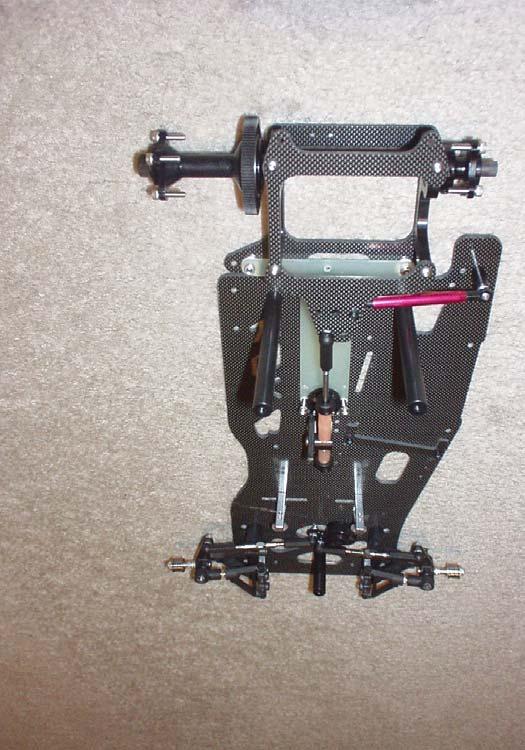
2 CHASSIS KIT FEATURES Black Carbon Fiber Chassis Components 2.5 mm Thick Main Chassis Battery mounting locator for LiPO, 4-cell and 6-cell battery packs Ballast Weight mounting holes 2-Position T-Plate Mounting Option (Centered & Offset) 2-Position Rear Pod Mounting Option (Centered & Offset) 5-Position Adjustable Center Shock Mount Adjustable Position Nerf Wing Adjustable Front Track Width Option On Each Side Of Car All Required Aluminum & Steel Fasteners Motor Pod plates CRC Side dampener tube KSKt Racing spec Center dampener screw-on Body Post Set Kimbrough Products Servo Saver Kimbrough Products Spur Gear Grade 7 Steel Front & Rear Bearings Complete Rear Differential Steering Ti-rods Team Associated Dynamic Strut Front End Components T-Plate Angled Aluminum Servo Mounts Thanks for purchasing another innovative product from KSKT Racing Products and Darkside Motorsports. The KSKB represents the best open wheel 1/10 spec racing chassis kit available. This chassis incorporates nearly 20 years of oval racing research and development. The kit comes with the finest components on the market, it wins at the highest levels of competition straight out of the box. Before you begin assembly of the chassis, take a minute to familiarize yourself with all of the parts that are included with the kit. The instructions will have you assemble the chassis in a starting configuration for a flat track with a carpet surface. The parts that come with the kit are organized by bags and by individual steps. 2
3 ITEMS REQUIRED FOR ASSEMBLY Tools: 3/16 Nut Driver 5/16 Nut Driver 1/16 Allen Wrench.050 Allen Wrench 3/32 Allen Wrench Phillips Screw Driver X-Acto Knife Small Pliers Power Drill #43 Drill Bit (For 4-40 Screws) Countersink Drill Bit Ti-rod Adjustment Wrench Misc: Foam Bumper Servo Tape Thread Lock Double Sided Tape Sandpaper Camber gauge PARTS REQUIRED FOR OPERATION In addition to the parts included with this kit, you will need the following items: Parts: Dampener Lube Diff Lube Electronics Motor Battery Pinion Gear Body Tires CHASSIS ORIENTATION Throughout the instruction manual, there will be many references to the left and right side as well as the inside and outside of the chassis. Left and right refer to the side of the car as if you were actually sitting in the driver s seat. Inside refers to the left side of the car and outside refers to the right side of the car. CARBON FIBER PART PREPARATION Lightly sand the cut edges of all of the kit s carbon fiber parts and seal with a thin bead of super glue. This will reduce the risk of splitting the carbon fiber parts in a hard crash ALUMINUM PART PREPARATION We suggest that you use a 4-40 tap to clean out the all of the threaded holes on the black anodized aluminum parts. During the anodizing process, small surface imperfections are 3
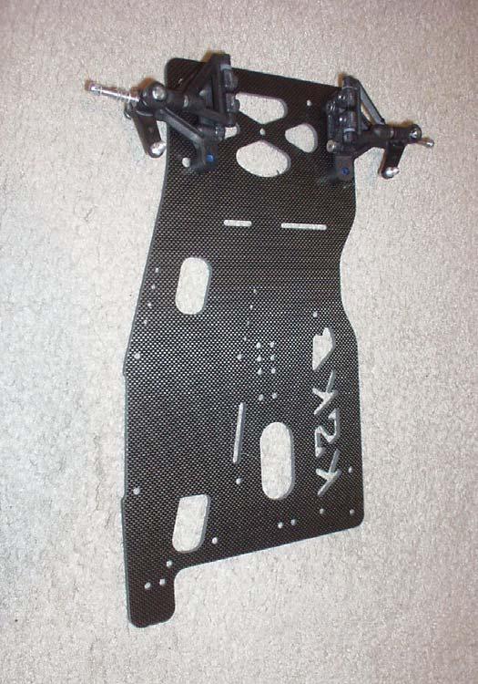
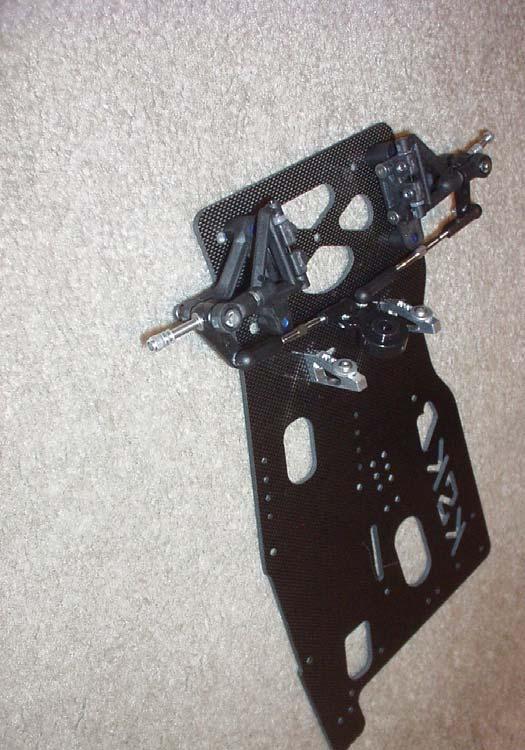
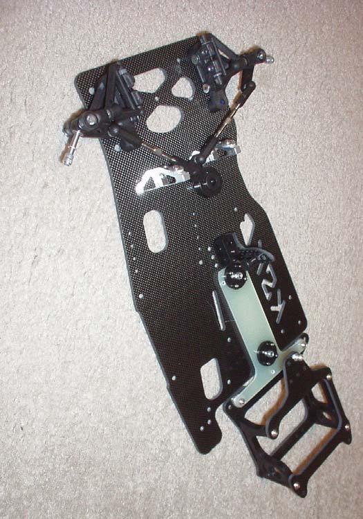
4 created in the threaded holes that may make screw insertion difficult. We also recommend running a steel screw through all of the aluminum locknuts prior to inserting aluminum screws. This will help to form a thread through the locknut. Taps and tap handles are available almost all Hope Depot s, Lowe s and Ace Hardware stores. 1) FRONT SUSPENSION Parts: 1 Pair of Associated Lower A-arms 1 Pair of Associated Upper A-arms 2 Steel Upper A-arm Turnbuckles 1 Pair Suspension Eyelets 4 Delrin Front Suspension Pivot Balls Aluminum Screws 1 Plastic Castor Block Set x 3/16 Set Screws Nylon Castor Block Shims 2 Upper A-Arm Hinge Pins x ½ Flat Head Screws 2 Front King Pins Aluminum Shims (For Stub Axles & King Pins) 4 - E-clips 2 Front Suspension Springs (.020 ) 2 Front Stub Axles x 1/8 Set Screws 1 Pair of Associated On-Center Steering Blocks 2 Standard Height Ball Studs 4 3/16 Aluminum Lock Nuts 4 Flanged Front Bearings (1/8 x 5/16 )(Packaged with the differential) Begin by inserting the delrin pivot balls into the lower suspension arms, with the shoulder facing up. We recommend using a pivot ball insertion tool for this so as to not damage the balls. Attach the castor blocks to the lower suspension arm using the four 4-40 flat head screws provided. Use a 5 degree block for the left side of the chassis and a 0 degree block for the right side. Attach the lower suspension arm to the chassis with the four 8-32 Phillips head screws provided. We recommend starting with the track width in the wide position. Install the pivot balls into the upper suspension arm eyelets. There are two different size holes on the eyelets, the larger is the bottom and the smaller is the top. Insert the ball into the large hole in the eyelet with the shoulder facing down Thread the upper suspension arm ti-rod into the upper a-arm and upper a-arm eyelet. Insert the steel stub axle into the plastic steering arm. Take one of the kingpins and slide it through the hole in the plastic steering arm & axle. It is critical that that the king pin s movement through this hole is smooth and free. Remove the king pin from the steering block once its movement is free and smooth. Take 10 small aluminum shims and install five on each axle followed by the 4-40 aluminum lock nut also included. These shims provide a fine adjustment for the front track width as well as wheel offsets. 4
5 Thread a standard length ball stud into the hole on the steering block farthest away from the kingpin and secure with a 4-40 aluminum locknut. Slide the upper a-arm hinge pin through the upper a-arm. Castor is adjusted by using the small plastic shims. We recommend beginning with 1 2 degrees of negative caster (kingpin leaning to the rear of the chassis) on the right side and 2 3 degrees of negative caster on the right side of the car. It is critical that the upper suspension arm is free and not bound up. Use the 5-40 x 3/16 set screws to secure the upper a-arm in the desired. These set screws are installed into the side of the castor blocks. Install an e-clip on one end of the king pin. Next slide on one of the suspension springs and slide this assembly through the pivot ball in the lower arm, installing it from the bottom. Once the king pin is through the upper a-arm, slide on two aluminum shims and then attach the upper e-clip. Repeat for the other side of the chassis. Adjust the length of the upper a-arms to gain the proper amount of camber in the front tires. Camber is the reference to the amount of lean that the front tires are leaned from a perfectly vertical line. In general on oval cars, set-up the chassis such that both tire are angled to the left side of the chassis. Thus, the left side tire leans away from the car and the right side tire leans to towards the car. Camber is the main means of adjusting the front end so that the front tires are wearing square and not in a cone shape. Camber is an adjustment that generally will not vary much front track to track, but will vary between flat and banked tracks. Once the front suspension is assembled, insert one of the 1/8 set screws into the threaded hole on backside of each of the stub axles. This will help keep the front end tight and smooth. 2) STEERING COMPONENTS Parts: 1 Kimbrough Servo Saver 1 Kimbrough Servo Saver Adaptor 1 Servo Saver Phillips Head Screw 2 Standard Length Ball Studs 4-3/16 Aluminum Locknuts 4 Plastic Ball Cups Titanium Steering Turnbuckles 2 Angled Aluminum Servo Mounts x 5/16 Flat Head Screws /8 BH Screws 2 Washers Install the two standard length aluminum ball studs into the servo saver holes farthest away from the center-mounting hole. The balls are to project off of the servo saver on the side opposite the one that mounted to the servo. Secure the ball studs with two 4-40 aluminum locknuts. Attach the servo saver to the servo using the servo saver adaptor that corresponds to the make of servo that you are using. Slide the servo saver onto the servo and secure with the Phillips head screw provided Mount the servo onto the two angled aluminum servo mounts using 2 button head screws and the washers provided. 5
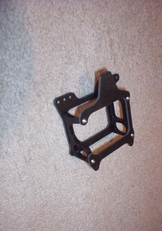
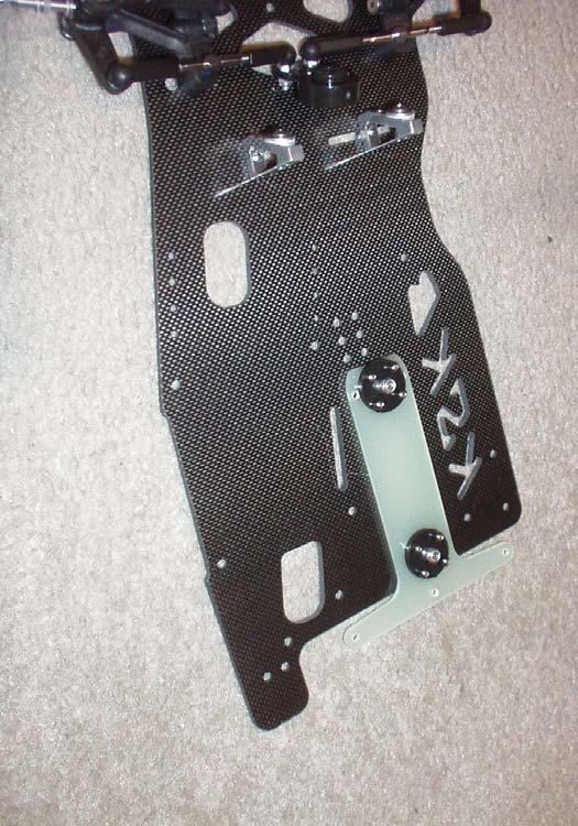
6 Mount the servo assembly to the main chassis with the remaining two 5/16 aluminum flat head screws and two 3/16 aluminum locknuts. The chassis is predrilled with slots to help make the installation of the servo easier. Make certain that the servo saver is centered in the chassis. Thread the plastic ball cups onto the titanium ti-rods to an overall length of approximately Snap the ti-rods onto the ball studs on both the servo saver and the steering blocks. Adjust the length of the steering ti-rods so that the front tires are parallel to each other. 2) MOTOR POD Parts: 1 - Black Carbon Fiber Top Plate 1 - Black Carbon Fiber Bottom Plate 1 - Black Anodized Aluminum Motor Mount 1 - Black Anodized Aluminum Left Side Mount 4-5/16 Button Head Screws 4-5/16 Flat Head Screws 1 - Short Aluminum Ball Stud 1-3/16 Aluminum Lock Nut 1 Plastic Ride Height Adjustor Set Attach the motor mount to the carbon fiber bottom plate using 2 5/16 flat head screws. Attach left side axle carrier block to the carbon fiber bottom plate using 2 5/16 flat head screws. The blocks have a stepped recess for the plastic axle carriers. This recess is to face each outside of the motor pod. Attach the aluminum ball stud to the top of the carbon fiber top plate using the 3/16 aluminum lock nut. The ball stud is to be mounted in either the standard or offset position to match the mounted location of the t-plate on the bottom. Attach the top plate to the aluminum motor plates using 4 5/16 button head screws. Install the desired ride height adjustors into the motor pod plates. 3) T-PLATE ASSEMBLY Parts: 1 T-Plate Button Head Screws 2 T-Plate Pivot Balls 2 Pivot Ball Cups x ½ Cap Head Tweak Screws x ½ Flat Head Screws 2 1/16 Aluminum Spacers 4 3/16 Aluminum Locknuts Install the pivot ball cups and pivot balls into the t-plate using the 2-56 button head screws provided. The pivot ball cups are installed on what will become the top of the t-plate and are fastened to the t-plate from the bottom. It is critical that the pivot ball is tight but free in the plastic cups. A bound up pivot ball will cause the car to handle poorly. 6
7 Attached the t-plate assembly to the motor pod lower plate. This is accomplished by using the 1/16 aluminum spacer washers, 4-40 x 3/8 flat head screws and the 3/16 aluminum lock nuts. The spacers go between the carbon fiber lower plate and the t-plate; the locknuts are installed on the top of the t-plate. When using the fiberglass t-plate that comes with the kit, use only 1 spacer washer per hole. Attach the motor pod/t-plate assembly to the main chassis using the 4-40 x 1/2 flathead screws and two 3/16 aluminum locknuts. Mount the t-plate in the set of mounting holes to the right side of the car. This is the standard and centered mounting position. Once the motor pod/t-plate assembly is attached to the main chassis, rotate the pod through its range of movement. Check to see that the pivot balls are tight & free, but not loose in the pivot ball sockets. If either of these conditions is present, remove and reinstall the pivot balls. The bottom plate offers a standard as well as an offset mounting location for the t- plate. For the base assembly, attach the t-plate to the motor pod in the offset position, shifting the pod to the left in the car. Refer to the set-up tips for information on offsetting the rear pod. 4) CENTER DAMPENER MOUNT Parts: 1 - Black Carbon Fiber Center Shock Mount 1 - Delrin Center Shock Anchor Block 1 - Plastic Center Shock Bushing 1 1/4 Steel Button Head Screw 2-5/16 Button Head Screws 2-5/16 Flat Head Screws On the delrin anchor block, you will notice one unthreaded hole. This hole is to be located towards the front of the car. This hole is for the antenna tube that will be installed later. Attach the carbon fiber shock mount to the right side (outside of the chassis) of the delrin anchor block with 2 5/16 button head screws. Take the 5/16 button head screw and install it in the desired hole on the carbon fiber shock mount. Refer to the set-up tips page for more on the various mounting locations on the center dampener. To begin with, mount the center dampener mount in the standard or centered mounting location on the chassis matching the location of the t-plate. Mount the center dampener mount in the set of holes closest to the front of the t-plate. The initial shock position will be in the center of the five hole range. The button head will be on the outside of the carbon fiber piece, the threaded end facing the inside of the chassis. Thread on the plastic shock bushing. The hole perpendicular to the threaded hole will be where the center dampener rod will pass. Be certain to keep this in the general angle of the center dampener rod. The completed shock mount is attached to the chassis using 2 5/16 flat head screws in the appropriate holes just to the front of the t- plate mounting holes. 5) BODY POSTS Parts: Front Body Post Long Body Posts x ½ Steel Flat Head Screw 7
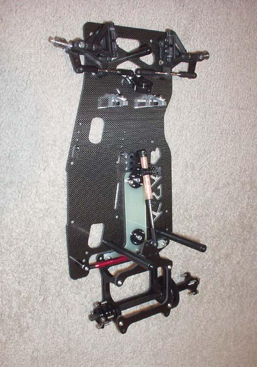
8 3 5/16 Steel Button Head Screws The front body post is attached to the chassis in the center hold between the front suspension arms using the 4-40 x ½ flat head screw provided. The long rear body posts are attached to the chassis on the right side of the t-plate and on the left side just behind the rear battery tape slots using the remaining 4-40 x ½ flat head screws provided. 3 5/16 steel button head screws are included to anchor the body to the front and center body posts. 6) SIDE DAMPENER TUBE Parts: Steel Ball Studs Nylon Locknuts 1 Aluminum Dampener Tube Cylinder 1 Plastic Dampener Tube Plunger 1 Plastic Dampener Tube Tie-rod End 1 Plastic Open End Dampener Tube Tie-rod End Threaded Set Screws Aluminum Ball Stud Short Steel Set Screw 1 Aluminum Standoff x 5/16 Flat Head Screw Install the aluminum standoff onto the chassis with the 4-40 flat head screw. There are two mounting holes on the chassis for this standoff. Install the standoff in hole that corresponds to the location of the t-plate (Centered of offset). Install the 4-40 aluminum ball stud into the aluminum standoff. Install the 2-56 steel ball stud into middle hole on the bottom side of the motor pod top plate and secure with the 2-56 aluminum lock nut provided. Attach the plastic rod end with the open end to the threaded end the aluminum dampener tube cylinders with the short 4-40 threaded setscrew. Attach the other plastic rod end to the threaded end of the plastic dampener tube plunger with the 5/ threaded set screw. Place you dampener tube fluid of choice on the plunger end and inset into the aluminum cylinder. We recommend using 7,000 weight silicone lube. Attach the dampener tube s aluminum end to the top of the chassis mounted aluminum standoff. Attach the other end of the dampener tubes to the bottom side of the motor pod top plate. 7) CENTER DAMPENER Parts: 1 Steel Dampener Rod With Threaded End 2 Steel Dampener Tube Collars 1 Plastic Rod End 1 Short Length of Silicone Fuel Tubing 1 Long Length of Silicone Fuel Tubing 8
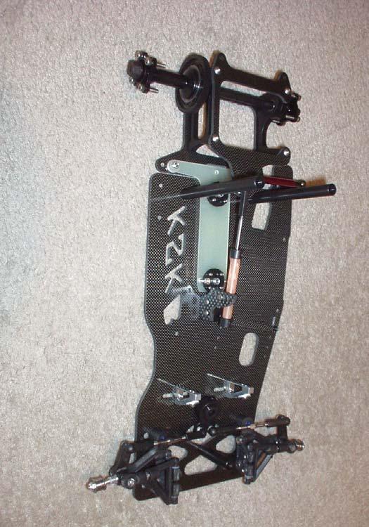
9 Thread the plastic rod end onto the dampener rod as far as possible until the shaft will not easily thread into the plastic rod end any further. Slide on one of the steel dampener tube collars and tighten the set screw. This should be about ¼ from the end of the plastic rod end. Slide on the long length of fuel tubing. Slide this assembly through the plastic bushing on the center dampener mount. Clip the plastic rod end onto the ball stud on the motor pod top plate. Slide on the short length of fuel tubing. Slide on the other steel dampener tube collar and tighten the set screw. There should be about 3/8 between the plastic bushing and the lower steel collar. The chassis ride height is adjusted by varying the distance between the center bushing and the steel collars. Put a small amount of the same dampening fluid used for the side dampener on the fuel tubing and dampener bushing to make the action smoother 9) REAR DIFFERENTIAL Parts: 1 Rear Differential Set 5 Flanged Rear Bearings (1/4 x 3/8 ) 1 Kimbrough Spur Gear x ½ Steel Cap Screws 5 Steel Axle Spacer Shims Diff Lube (Not Included With Kit) Hold the axle vertically and slide one flanged bearing on to the short end of the rear axle. Make sure that the flanged side is placed against the axle s collar. Place 1 diff ring onto the axle and align notch in the ring with the notch on the axle collar. Place the spur gear onto the axle collar and diff ring. Place a small amount of differential lube into each of the 12 holes in the outer ring of the spur gear and insert the twelve-diff balls into the spur gear. Take the right side hub and insert 1 bearing into each end. Place the other drive ring onto this hub. Slide the right side hub onto the axle making certain that the drive hubs stay seated on the axle collar and hub. For the base set-up with the motor pod offset left, we recommend beginning with the longer of the two right side hubs included with the kit. Slide the black axle spacer onto the axle, narrow side towards the hub. Tighten the plastic locknut down onto the spacer. The differential will be adjusted once the chassis is fully assembled. Install the bearings into the rear axle carriers and insert the completed rear differential. Install the completed differential through the rear pod bearings. The spur gear is to be installed on the right side of the chassis. Slide on 3 steel axle spacer washers onto the left side of the axle Slide on 2 steel axle spacer washers onto the right side of the axle Install and tighten the left side axle hub. The hub should be tight against the spacer such that it has very little side play. 9
10 COMPLETING THE CHASSIS To complete the chassis and get it ready to race, the following steps need to be completed. Install the electronics. Install Tires Once the tires are installed, hold one rear tire in each hand and try to rotate the spur gear with your right thumb. A properly tightened differential will be difficult to rotate. Make certain that the differential is not too tight. Mount the body Set the chassis tweak. We recommend the rear tweak is set such the right rear tire lifts about 1/8 off the ground before the left rear is lifted off of the ground. This is measured by lifting the chassis off the ground from a point on the bottom plate in the center of the read pod. Go racing! SET-UP TIPS Any chassis is only as good as its ability to be adapted to a particular track configuration as well as individual driving characteristics. The KSKB has been designed to offer a vast range of adjustment options. These options make the this chassis adaptable to nearly any track condition that is found in racing today. Listed below are several of the tuning options that have been designed into the chassis. Give the numerous set-ups possible, we recommend that you make only one change at a time so as to learn exactly what the on-track reaction is. Once you have established a base-line set-up for a particular track. Write down this set-up so that if the car s handling begins to fall off, you can return to this baseline set-up. Understand the there is no right chassis set-up, it is best to work with the car and fine what works best for your driving style. RIDE HEIGHT We recommend beginning with the overall chassis right height, both front and rear at between 5mm to 7mm. Having chassis sloped to the front will tend to increase the steering aggressiveness. Conversely, having the chassis sloped to the rear will reduce the steering and will tend to under steer when exiting the turn. CENTER DAMPENER MOUNTING HEIGHT There are 5 mounting locations on the forward center dampener mount. The lower the center dampener is mounted to the chassis, the more progressive the compression rate. As the center dampener is mounted higher and with less angle, the more linear the compression rate. The higher the center dampener is mounted; the more weight gets transferred to the front of the chassis under load. The center dampener mount is designed such that the center shock can be raised and lowered without changing its length. This feature allows quick changes to speed tuning of the car to specific track conditions. 10
11 SIDE DAMPENER TUBE We recommend that you beginning with OFNA 7,000 wt fluid in the tube. Testing has shown this to be a good starting point. You will need to tune from there to suit the track conditions and layout. Thinner weight fluid will decrease the car s front traction and steering. Thicker weight fluid will increase the car s front traction and steering. Fluid that is too thick will tend to want to lift the inside rear tire off of the track in a turn. FRONT SPRINGS The recommended kit set-up for the chassis has the same rate springs on each side of the chassis. When tuning your chassis to a particular track surface, the following is a good rule of thumb: A softer left front spring will give more steering from the center of the turn, off. A stiffer left front spring will give less steering from the center of the turn, off. A softer right front spring will give more steering at the entry of the turn A stiffer right front spring will reduce the amount of initial corner turn-in. FRONT TRACK WIDTH The front track can be adjusted by using the small aluminum shims on the stub axles as well as the location where the suspension arms are mounted to the chassis. Moving the right front closer to the centerline of the chassis will increase the amount of weight transferred while cornering, thus increasing steering entering the turn, moving the right front further away from the centerline of the chassis will have the opposite result. Moving the left front tire in and out will have the similar result but is not as critical for corner entry. Adjustments to the left front tire will have a more noticeable result on corner exit. We recommend that you begin the track width set for the wide track width position and that adjustments are made from that point. Generally, a wider overall front track will have less steering than a narrower overall front track. REAR TRACK WIDTH The rear track width can be adjusted by adding shims between the axle carrier bearings and the hub or axle collar. The kit also comes with 2 different width right side hubs for further adjustment. Mounting the left rear tire closer to the motor pod will make the car rotate more efficiently through the turn and reduce the amount of steering entering the corner and decrease steering off. Mounting the left rear tire further away from the motor pod will increase the amount of weight transferred to the front of the car, thus increasing steering from the center off. Moving the right rear further away from the motor pod will increase the amount of steering from the center of the turn off and will reduce entry steering. Moving the right rear tire closer to the motor pod will increase steering from the of the corner. 11
12 REAR POD OFFSET The motor pod s lower plate offers two mounting locations for the t-plate. The standard location keeps the motor aligned with the center axis of the chassis. The offset location, moves the motor to the left side of the chassis approximately 5/16. Offsetting the pod to the left will help plant the left rear tire under acceleration off of a turn. The ball studs for the center and side shocks on the top plate need to be in either the standard or offset location to match the location of the t-plate. When the motor pod is offset to the left, the longer right side diff hub is also utilized to keep the right rear tire in the proper location. T-PLATE OFFSET The KSKB chassis offers two different mounting locations for the t-plate on the main chassis. This adjustment will provide more left side weight and is beneficial for flat tracks that demand an aggressive steering set-up. The standard location where the t- plate is mounted along the centerline of the chassis, and the offset position that moves the t-plate towards the left side of the chassis. When mounting the t-plate in the offset location, the rear shock tower needs to be mounted in the offset position and the t-plate needs to be mounted to the lower pod plate in the standard position. The center shock mount will need to be moved towards the left side of the chassis in the offset t-plate configuration. NERF WING The nerf wing has two mounting options. The nerf wing should be mounted so that its outer edge just touches the inside of the body. This will be dependent upon both the battery tray location as well as how the body is mounted to the chassis. Good luck with your new chassis. Visit our website to see what new products are available for this chassis. If you have any set-up questions, feel free to contact us at or by at info@darksidems.com and we will be happy to offer assistance. 12
13
14

15 * ) / ) REMOVE THESE PARTS FOR: SPORT: steps 2-3 TEAM: steps , qty 2 spacer 8439, qty x 5/8 blue aluminum , 6917, qty x 3/8 4187, qty 4 spacer 8413, qty 4 caster shim 8423, qty 2 kingpin 1/16",.050" 6299, qty 6 E-clip 4448, qty 2 ball end blue aluminum 4449, qty locknut 8429, qty 2 spring, , qty 10 kingpin shim 3213, qty 2 axle 8403, qty 1 cross brace 8421, qty 2 offset steering block 8413, qty 2 hinge pin IJAF FILE THE CHASSIS Use your file to bevel the slots on the top of the chassis so the edges won't cut through the battery cell wrap. WARNING! Graphite dust can be harmful to your health. File in a well ventilated area. Then wash the chassis with running water and dry with paper towels. Wash your hands afterward with cold water and soap. Deposit graphite filings in trash. TAPE THE CHASSIS Insulate the battery slots by wrapping the slots with electrical tape. NOTE: The bottom of the chassis has the screw holes countersunk. SPORT ONLY: #8480. TEAM ONLY: #8474. IJAF! , - SUSPENSION ARMS TO CHASSIS Slip the #8179 spacer between the suspension arm and the chassis, then bolt on with two #8439 blue aluminum screws from underneath the chassis. Do the other side. MOUNT THE CROSS BRACE Mount the #8403 cross brace to the front suspension using two #6917 button head screws chassis 8439 FRONT VIEW SHOWN the side with the rounded corner should face up UPPER ARM TO THE SUSPENSION MOUNT Assemble the upper arm assembly to the suspension mount as shown, using the #8413 hinge pin and #8413 shims FINAL FRONT SUSPENSION ASSEMBLY Assemble the #8421 steering block as shown using parts #3213, 6299, 4448, 4187, and Install the ball end into the rear hole. Place one #6299 E-clip on the bottom of the #8423 kingpin then slide the #8429 spring over. Slide the #8423 kingpin completely through the bottom of the suspension arm and up through the steering block. Place one #8425 shim on top of the #8421 steering block. Now push the upper arm over the kingpin. Place four #8425 shims over the kingpin and secure with a #6299 E-clip. 9 Do the other side FRONT VIEW SHOWN
16 4 - ) / 7 5 CUSTOMER SUPPORT (714) FAX (714) web site: Associated Electrics, Inc. ASSOCIATED ELECTRICS, INC Cadillac Ave. Costa Mesa, CA USA * * 7 1, 1 / OPEN THE BAGS IN ORDER The assembly is arranged so that you will open and finish that bag before you go on to the next bag. Sometimes you will have parts remaining at the end of a bag. These will become part of the next bag. Some bags may have a large amount of small parts. To make it easier to find the parts, we recommend using a partitioned paper plate for spreading out the parts so they will be easier to find. MANUAL FORMAT The following explains the format of these instructions. The beginning of each section indicates: 1 Which bag to open ("BAG A") and which kit uses those parts, whether Sport or Team. 2 Which parts you will use for those steps. Remove only the parts shown. "" indicates an actual size drawing; place your part on top and compare it so it does not get confused with a similar part. 3 Which tools you should have handy for that section. 4 In some drawings, the word "REAR" with an arrow indicates which direction is the rear of the car to help keep you oriented. 5 The instructions in each step are ordered in the order you complete them, so read the words AND follow the pictures. The numbers in circles are also in the drawing to help you locate them faster. 6 When we refer to left and right sides of the car, we are referring to the driver's point of view inside the car. SUPPLEMENTAL SHEETS We are constantly developing new parts to improve our kits. These changes, if any, will be noted in supplementary sheets located in a parts bag or inside the kit box. Check the kit box before you start and each bag as it is opened. When a supplement is found, attach it to the appropriate section of the manual. Now clear off your workbench, line up some paper plates, grab your 50-cent soda, 39-cent cheeseburger, $12.99 music CD, and let's begin! * ) / ) , REMOVE THESE PARTS FOR: SPORT: step 1 TEAM: step , qty 2 upper suspension arm 8415, qty 2 upper suspension arm turnbuckle 8407, qty 2 0 upper suspension arm lower suspension 8419, qty 2 mount arm 8417, qty 4 pivot ball 8411, qty 2 upper suspension arm eyelet 8409, qty x 1/2" shoulder screw, blue aluminum 1/16" IJAF , ASSEMBLE UPPER SUSPENSION ARM Assemble parts #8405, 8415, and ATTACH UPPER ARM MOUNT TO LOWER ARM Attach # mount to the #8419 lower suspension arm using two #8409 screws. WARNING! Screws are difficult to screw in. Turn carefully so you do not strip out the head. INSTALLING UPPER AND LOWER PIVOT BALLS Before popping in the #8417 pivot balls, make sure there are no burrs inside the pivot ball holes. Pop the #8417 pivot balls into the suspension arms as shown. Make sure that the shoulders of the pivot balls in the lower suspension arms are facing upward and the pivot balls in the upper arm are facing downward as shown. Orient ball to the rounded side of the upper arm as shown. Now assemble the right side (blue) right side (blue) F R O N T left side 8417 Match this number to the text to find your way faster 8411 shoulder down the side with the rounded corner should face up shoulder up 3

17
Bag 1. Bag 1. Center Pivot. Center Pivot
 8 00734 01901 5 Center Pivot Bag 1 3374 - Center Pivot Socket 4019 - Alum Pivot ball 3254-2-56 Button Head *Note - Sometimes it is helpful to slightly over-tighten the top clamp screws, then work the ball
#4016 KIT TOOLS SUPPLIED
 #4016 4 =? A F H L A, O = E? 5 J H K J BH JIKIFA IE.=?J HO6A= + = H > B E > A H > K A = K E K I? H A M + I F I E J A + D = I I E = @ > = A @ I 9 E @ A > = J J A H O I JI.=?J HO6A= > K A J E J = E K JK
Assembly Manual. 1/10th Formula 1 Car
 Assembly Manual 1/10th Formula 1 Car Center Pivot Bag 1 3374 - Center Pivot Socket 40194 - Hard Anodized Alum Pivot ball 3254-2-56 *Note - Sometimes it is helpful to slightly over-tighten the top clamp
Assembly Manual. 1/10th World GT car
 Assembly Manual 1/10th World GT car Center Pivot Bag 1 3374 - Center Pivot Socket 40194 - Hard Anodized Alum Pivot ball 3254-2-56 Button Head *Note - Sometimes it is helpful to slightly over-tighten the
RJS2021 LTO SPORT OVAL RACER LESS ELECTRICS
 RJS2021 LTO SPORT OVAL RACER LESS ELECTRICS THANKS FOR BUYING THE RJ SPEED 1/10 LTO SPORT KIT FOR OVAL RACING. THE ASSEMBLY WILL NOT BE DIFFICULT IF YOU READ THE TEXT, LOOK AT THE PICTURES, AND THE EXPLODED
RJS2020 SPORT 3.2 1/10 PAN CAR KIT LESS ELECTRICS
 RJS2020 SPORT 3.2 1/10 PAN CAR KIT LESS ELECTRICS THANKS FOR BUYING THE RJ SPEED 1/10 SPORT 3.2 KIT. THE ASSEMBLY WILL NOT BE DIFFICULT IF YOU READ THE TEXT, LOOK AT THE PICTURES, AND THE EXPLODED VIEW
J & D Machine / Hyperdrive / MSA 3711 Moon Bend Rd. Chapel Hill, TN 37034
 J & D Machine / Hyperdrive / MSA 3711 Moon Bend Rd. Chapel Hill, TN 37034 www.hyperdriveracing.com 1 You now own a state of the art 1/10 scale oval race car. The Hyperdrive Assault has gone through months
Shown with optional GFR-1017R Body Posts. J & D Machine / Hyperdrive / MSA 3711 Moon Bend Rd. Chapel Hill, TN
 Shown with optional GFR-1017R Body Posts J & D Machine / Hyperdrive / MSA 3711 Moon Bend Rd. Chapel Hill, TN 37034 www.hyperdriveracing.com 1 You now own a state of the art 1/10 scale oval race car. The
Calandra Racing Concepts
 Calandra Racing Concepts Carpet Knifeä Version 3 Assembly and Setup Manual Congratulations! You now own the best 1/12th scale car on the market today, the Carpet Knifeä Version 3. This completely new car
Bag 1. Bag 1. Center Pivot. 3 Center Pivot Cap. Center Pivot
 Battle Axe 2.0 1:10th Oval Weapon from Team CRC Assembly Manual 0 2. e Ax s tle Win s! t rd Ba s + bi C. ow CR T.Q Sn 0 20 servo and saver not included Part # 100 Calandra Racing Concepts 6785 Martin Street
2030 OUTLAW SPRINTER HARDWARE I.D. BUTTON HD. CAP SCREW BAG H1 CHASSIS KIT BAG H3 HARDWARE BAG L2 REAR AXLE PARTS BAG L4 FRONT TIRES
 THANKS FOR BUYING THE RJ SPEED OUTLAW SPRINTER KIT. IT IS COMPLETE LESS ELECTRICS, AND MADE FOR CARPET OR PAVEMENT RACING. IT REQUIRES A 540 OR 550 SIZE MOTOR, 4 OR 6 CELL BATTERY PACK, TWO CHANNEL RADIO
RJS WB ELECTRIC T/F DRAGSTER KIT LESS ELECTRICS
 RJS2006 30 WB ELECTRIC T/F DRAGSTER KIT LESS ELECTRICS THANKS FOR BUYING THIS RJ SPEED DRAGSTER KIT. IT IS MADE FOR STRAIGHT LINE DRAG RACING AND MAY BE BROKEN IF RUN INTO SOLID OBJECTS REPEATEDLY AT HIGH
1:12 SCALE ON ROAD CAR KIT
 2 SCALE ON ROAD CAR KIT INSTRUCTION MANUAL OR KIT #4015 SAVE VE THIS MANUAL! Use with current catalog for future, hassle-free re-ordering of parts. 1998 Associated Electrics, Inc. - 9? D = I I EI @ A I
INSTRUCTIONS MANUAL COMPETITION GRADE HIGH PERFORMANCE RADIO CONTROL RACING CAR CHASSIS KIT 1/12 SCALE ELECTRIC COMPETITION CAR KIT
 COMPETITION GRADE HIGH PERFORMANCE RADIO CONTROL RACING CAR CHASSIS KIT 1/12 SCALE ELECTRIC COMPETITION CAR KIT INSTRUCTIONS MANUAL E Thank you for purchasing VBC Racing product. Things that we should
RJS2017 SPORTSMAN RACER KIT LESS ELECTRICS
 RJS2017 SPORTSMAN RACER KIT LESS ELECTRICS THANKS FOR BUYING THE RJ SPEED 1/10 SPORTSMAN RACER KIT FOR OVAL RACING, DRAG RACING OR JUST FUN STREET BASHING. THE ASSEMBLY WILL NOT BE DIFFICULT IF YOU READ
McDominator Team Kit Owner's Manual
 McDominator Team Kit Owner's Manual Thank you for purchasing the McPappy Racing McDominator Team Kit. This manual will guide you through the assembly process. It is possible to take a kit and throw it
.050 Allen key 1.5mm Allen key 1/16 Allen key 5/64 Allen key 3/32 Allen key Turnbuckle & 3/16 wrench
 1 Thank you for purchasing the Outlaw 4 Sprint Car! The Outlaw sprint car platform has been developed for loose dirt buggy tire racing. In this kit you will find the 4 th evolution of the car which features
INSTRUCTIONS MANUAL COMPETITION GRADE HIGH PERFORMANCE RADIO CONTROL RACING CAR CHASSIS KIT 1/10 SCALE ELECTRIC COMPETITION CAR KIT
 COMPETITION GRADE HIGH PERFORMANCE RADIO CONTROL RACING CAR CHASSIS KIT 1/10 SCALE ELECTRIC COMPETITION CAR KIT INSTRUCTIONS MANUAL E Thank you for purchasing VBC Racing product. Things that we should
7207 FRONT BULKHEAD, nylon FRONT BULKHEAD ALUMINUM SUPPORT HINGE PIN, inner, with clips, 1.675" pr GT RACING FRONT
 RC10GT & RTR GT MC 9 McCOY GLOW PLUG 1 3.9 2661 CLUTCH NUT CLIPS 6.7 3216 WASHER, #4 12 1.00 3719 NYLON WIRE TIES, 6" heavy duty 12 2.00 3720 NYLON TIES, 8", light duty for receiver 12 2.00 3721 SELF-TAPPING
OWNER'S MANUAL Magnolia Ave., Chino, CA phone: (909) fax: (909)
 fax: (909)") OWNER'S MANUAL Carefully read through all instructions to familiarize yourself with the parts, construction techniques, and tuning tips outlined in this manual. Being able to grasp the overall design of
OWNER'S MANUAL Carefully read through all instructions to familiarize yourself with the parts, construction techniques, and tuning tips outlined in this manual. Being able to grasp the overall design of
2103 NITRO RAIL DRAGSTER KIT
 203 NITRO RAIL DRAGSTER KIT THANKS FOR BUYING RJ SPEED S NITRO DRAG KIT. IT IS A LITEWEIGHT CAR MADE FOR STRAIGHT LINE DRAG RACING AND CAN BE BROKEN IF RUN INTO SOLID OBJECTS AT HIGH SPEED. YOU WILL NEED
Install steering rack assembly to chassis using x 3/8 stainless flat head socket screws and 2-6.4mm x 1.1mm blue aluminum spacers as shown.
 Install steering rack assembly to chassis using 2-4-40 x 3/8 stainless flat head socket screws and 2-6.4mm x 1.1mm blue aluminum spacers as Qty 2, 4-40 x 3/8 fhcs Qty 2, 6.4mm x 1.1mm blue aluminum spacer
Dart 2.0 Owner's Manual
 Dart 2.0 Owner's Manual Thank you for purchasing the McPappy Racing Dart 2.0. This manual will guide you through the assembly process. It is possible to take a kit and throw it together in an hour. But
FIRST, A WORD ABOUT THE NEW RC12LC
 FIRST, A WORD ABOUT THE NEW RC12LC CONGRATULATIONS!! You have purchased the production version of the car that Masami Hirosaka used to win the 1996/97 IFMAR 1/12 scale On Road World Championships. This
OWNER'S MANUAL 2000 & ROAR National Champion
 2000 & 2001 ROAR National Champion OWNER'S MANUAL Carefully read through all instructions to familiarize yourself with the parts, construction techniques, and tuning tips outlined in this manual. Being
WARNING! Hard anodized, PTFE-coated shocks. Hard anodized, PTFE-coated MIP CVD's.
 200 Thank you for purchasing this Team Associated product. This manual contains steps and instructions you will use to set up your gas truck. Please read this entire manual before attempting to start your
ASSOCIATED 1:10 SCALE GT MANUAL
 ASSOCIATED 0 SCALE GT MANUAL INSTRUCTION MANUAL FOR THE RC10GT GAS TRUCKS #7060, 7061, 7067, 7068, & 7090 ASSOCIATED S RC10GT-- 3 TIMES NORRCA WORLD CUP CHAMPION! 200 Thank you for purchasing this Team
:: Additional Features Your new TC6 comes unassembled and requires the following items for completion. (refer to catalog section for suggestions):
:") 8/10 2 :: Introduction Thank you for purchasing this Team Associated product. This assembly manual contains instructions and tips for building and maintaining your new RC10TC6. Please take a moment to
8/10 2 :: Introduction Thank you for purchasing this Team Associated product. This assembly manual contains instructions and tips for building and maintaining your new RC10TC6. Please take a moment to
Dart 2.6 Team Kit Owner's Manual
 Dart 2.6 Team Kit Owner's Manual Thank you for purchasing the McPappy Racing Dart 2.6 Team Kit. (Note, many of these pictures still reflect the Dart 2.5. The very last section shows the 2.6 updates.) This
RJS2001 PRO STOCK KIT LESS ELECTRICS
 RJS2001 PRO STOCK KIT LESS ELECTRICS THANKS FOR BUYING RJ SPEED S PRO STOCK DRAG KIT. IT IS MADE FOR STRAIGHT LINE DRAG RACING AND CAN BE BROKEN IF RUN INTO SOLID OBJECTS REPEATEDLY AT HIGH SPEED. IT REQUIRES
#0980 Intimidator 7 Direct Drive Racing Kit
 #0980 Intimidator 7 Direct Drive Racing Kit 1 Thank you for purchasing the Intimidator 7! Within this kit you will find a race winning car with over 30 years of Custom Works design and quality. The latest
E Thank you for purchasing VBC Racing product. COMPETITION GRADE HIGH PERFORMANCE RADIO CONTROL RACING CAR CHASSIS KIT INSTRUCTIONS MANUAL
 COMPETITION GRADE HIGH PERFORMANCE RADIO CONTROL RACING CAR CHASSIS KIT 1/10 SCALE ELECTRIC COMPETITION FORMULA CAR KIT INSTRUCTIONS MANUAL E Thank you for purchasing VBC Racing product. Things that we
ABC HOBBY ORIGINAL RADIO CONTROL CAR
 ABC HOBBY ORIGINAL RADIO CONTROL CAR Instruction Manual Study the instructions thoroughly before assembly. FRONT WHEEL DRIVE NEW STYLE STRUT SUSPENSION BATHTUB CHASSIS 4 BEVEL GEAR DIFFERENTIAL FULL ADJUSTABLE
BEFORE YOU START CUSTOMER SUPPORT
 BEFORE YOU START The X10 is a high-quality, 1/10-pan car intended for persons aged 16 years and older with previous experience building and operating RC model racing cars. This is not a toy; it is a precision
BEFORE YOU START. XRAY USA RCAmerica, 167 Turtle Creek Boulevard Suite C Dallas, Texas 75207, USA
 BEFORE YOU START The X12 is a high-quality, 1/12-pan car intended for persons aged 16 years and older with previous experience building and operating RC model racing cars. This is not a toy; it is a precision
1:8 SCALE CATALOG 1:8 GAS KITS RC500 FRONT END BODY ACCESSORIES
 1:8 SCALE CATALOG Stock is extremely limited. Parts listing as of 7/2001. Sale prices apply to orders direct from Associated only. Items available while supplies last. Items marked Not available or are
ROLL CENTER You can adjust the front and rear roll centers of the XB8 by changing the mounting locations of various components.
 Your XRAY XB8 luxury nitro buggy is a top competition, precision racing machine that features multiple adjustments that allow you to set up for any track condition. The XB8 includes innovative set-up features
R R11 Eccentric Hub-Alu (4) R R11 Eccentric Hub-Alu (4) NOTICE. Pulley cover direction NOTICE BAG 01 NOTICE BAG 01
 R R11 Eccentric Hub-Alu (4) NOTICE. Pulley cover direction NOTICE BAG 01 NOTICE BAG 01") BAG BAG R Spool Axle Alu RA Front Spool Pulley Set 8T (4pcs) R Diff Gears (with Axle) Trim any excess flashing from the diff gear axle at the mold injection point. (pcs) (4pcs) R Spool Outdrive (pcs) R6
BAG BAG R Spool Axle Alu RA Front Spool Pulley Set 8T (4pcs) R Diff Gears (with Axle) Trim any excess flashing from the diff gear axle at the mold injection point. (pcs) (4pcs) R Spool Outdrive (pcs) R6
ABOUT THE RC10T2 BEFORE YOU BEGIN
 ABOUT THE RC10T2 Congratulations on your new RC10T2 model truck kit purchase. We would like to tell you a little bit about your new truck and its history. Team Associated developed the first version of
BEFORE YOU START. XRAY Europe K Výstavisku 6992, Trenčín Slovakia EUROPE. XRAY USA RC America, 2030 Century Center Blvd #15 Irving, TX USA
 BEFORE YOU START The X12 is a high-quality, 1/12-pan car intended for persons aged 16 years and older with previous experience building and operating RC model racing cars. This is not a toy; it is a precision
First, check and record the camber and caster readings, they will be adjusted later.
 First, check and record the camber and caster readings, they will be adjusted later. The caliper-mounting bosses are machined perpendicular to the spindle so they are an excellent place for the level.
DIFFERENTIAL STEERING RACK
 BAG-A DIFFERENTIAL (2 Sets) +Driver Cap Screw Diff Ball Nylon Nut Thrust Washer Thrust Ball Diff Joint Cup A Allen Wrench 850 Bearing Diff Ring Diff Spring Nylon Nut 850 Bearing Diff Ring Diff Ball Ball
REQUIRED READING SUGGESTED TOOLS
 REQUIRED READING Thank You and Congratulations on purchasing this INTIMIDATOR GBX! Within this kit you will find a race winning car with over 17 years worth of CUSTOM WORKS design and quality. In order
$1.00 FOR THE TQIO/RCIO
 $1.00 FOR THE TQIO/RCIO m mm HDBBYSHOP Champion Jay Halsey has an impressive track record. One of Jay's advantages is a whisper smooth tranny thanks to his dad, Jim. Now you can build a Halsey transmission!
Pinion Gear and Setscrew
 XRAY T1 Factory Kit 2005 The new XRAY T1 Factory Kit '05 (T1FK'05) is the 5th generation of XRAY's extremely successful T1 family of 1/10-scale on -road electric touring cars. The T1FK'05 is a large evolutionary
carbon fiber before assembly. Sand glue to the edges and
 chassis and carbon fiber give you a before assembly. Sand glue to the edges and 5 BAG MARKED CA BAG MARKED M3x6 Flathead 4 03 4 05 BAG MARKED 2 10 13 Installing Steering System Shock Assembly M4x28
OWNER'S MANUAL. Take your time and pay close attention to detail. Keep this manual for future reference. MADE IN THE UNITED STATES OF AMERICA
 OWNER'S MANUAL Carefully read through all instructions to familiarize yourself with the parts, construction techniques, and tuning tips outlined in this manual. Being able to grasp the overall design of
along with standard XT2 Instruction Manual and also XT2 18 Supplementary Sheet.
 Use this XT2 Dirt Conversion Supplementary Sheet along with standard XT2 Instruction Manual and also XT2 18 Supplementary Sheet. Parts included in Bag 8: 303141 SHIM 3x5x1.0MM (10) 322111 XT2 COMPOSITE
REQUIRED READING SUGGESTED TOOLS
 REQUIRED READING Thank You and Congratulations on purchasing this ENFORCER GSX! Within this kit you will find a race winning car with over 17 years worth of CUSTOM WORKS design and quality. In order for
The H-MAC Heavy Metal Articulating Chassis Construction Guide
 The H-MAC Heavy Metal Articulating Chassis Construction Guide The Heavy Metal Chassis is constructed with two identical drive modules built using 10 mechanical sub-assemblies. The drive modules are integrated
RJS2002 FUNNY CAR KIT LESS ELECTRICS
 RJS2002 FUNNY CAR KIT LESS ELECTRICS THANKS FOR BUYING RJ SPEED S FUNNY CAR DRAG KIT. IT IS MADE FOR STRAIGHT LINE DRAG RACING AND CAN BE BROKEN IF RUN INTO SOLID OBJECTS REPEATEDLY AT HIGH SPEED. IT REQUIRES
for the B3 Sport kit #9013
 All kit versions include: 2.40:1 transmission for effortless power handling. Molded composite chassis for better rigidity and Lexan B3 racing body. Quadra-symmetric suspension for greater stability and
COMPETITION GRADE HIGH PERFORMANCE RADIO CONTROL RACING CAR CHASSIS KIT SUPPLEMENTARY MANUAL FOR LIGHTNING KIT
 COMPETITION GRADE HIGH PERFORMANCE RADIO CONTROL RACING CAR CHASSIS KIT SUPPLEMENTARY MANUAL FOR LIGHTNING 10 235 KIT E Thank you for purchasing VBC Racing product. Things that we should remind you. This
RHINO SUSPENSION SYSTEM INSTALLATION INSTRUCTIONS
 PARTS INCLUDED: 2 FRONT UPPER A-ARMS 2 FRONT LOWER A-ARMS 2 UNI-BALL JOINTS 2 UNI-BALL JOINT STUDS 2 UNI-BALL JOINT CAPS 2 RETAINING RINGS 1 FRONT SHOCK ASSEM. 2 DELRON STEERING STOPS 2 SHOCK MOUNT SPACERS
LPE C5 Battery Relocation Kit
 LPE C5 Battery Relocation Kit The LPE C5 Corvette battery relocation kit improves vehicle weight distribution by moving weight to the rear of the vehicle. The improved weight distribution increases traction
NOTE: Using hot modified motors exceed the capacity of the electronic speed control and voids any warranty.
 OWNER'S MANUAL NOTE: Using hot modified motors exceed the capacity of the electronic speed control and voids any warranty. Carefully read through all instructions to familiarize yourself with the parts,
... REQUIRED READING...
 REQUIRED READING.........UNDERSTAND THIS MANUAL! Thank You and Congratulations on purchasing the OUTLAW! Within this kit you will find a race winning car with over 21 years worth of CUSTOM WORKS design
INSTRUCTION MANUAL INSTRUCTION MANUAL
 INSTRUCTION MANUAL INSTRUCTION MANUAL Thank you for purchasing Pro-Line s PRO-Fusion SC 4 4! For Over 35 years, Pro-Line has designed and manufactured the best RC products in the world. This 1:10 scale
ASSOCIATED 1:10 SCALE T3 MANUAL
 ASSOCIATED 0 SCALE T3 MANUAL INSTRUCTION MANUAL FOR THE RC10T3 ELECTRIC TRUCKS #7003, 7009, 7010, 7013, 7038, 7048 ASSOCIATED S RC10T3 TRUCK-- READER S CHOICE OF THE YEAR TIMES! Radio Control Car Action
Next, set the bar level and tighten it down. Do this on both the driver and passenger sides.
 Next, set the bar level and tighten it down. Do this on both the driver and passenger sides. Using two tape measures, measure the outside width at the front and the rear of the tubes. The front dimension
Manufactured By: CustomWorks RC Products LLC 760-B Crosspoint Drive Denver, NC #0928 ENFORCER GSX2 RACING KIT
 #0928 ENFORCER GSX2 RACING KIT Manufactured By: CustomWorks RC Products LLC 760-B Crosspoint Drive Denver, NC 28037 www.customworksrc.com REQUIRED READING.........UNDERSTAND THIS MANUAL! Thank You and
TIPS TO FINAL ASSEMBLY Radio installation. The Electronic speed control (ESC) and the receiver need to be mounted onto the chassis, using double sided
 and the receiver need to be mounted onto the chassis, using double sided") TIPS TO FINAL ASSEMBLY Radio installation. The Electronic speed control (ESC) and the receiver need to be mounted onto the chassis, using double sided tape (not supplied.) Mount the ESC first on the chassis
TIPS TO FINAL ASSEMBLY Radio installation. The Electronic speed control (ESC) and the receiver need to be mounted onto the chassis, using double sided tape (not supplied.) Mount the ESC first on the chassis
New Generation Rear Wheel Drive
 New Generation Rear Wheel Drive ABC HOBBY ORIGINAL RADIO CONTROL CAR Instruction Manual Study the instructions thoroughly before assembly. REAR 2 WHEEL DRIVE REAR MOUNTED MOTOR BELT DRIVE DOUBLE DECK CHASSIS
... REQUIRED READING...
 REQUIRED READING.........UNDERSTAND THIS MANUAL! Thank You and Congratulations on purchasing the DOMINATOR! Within this kit you will find a race winning car with over 25 years worth of CUSTOM WORKS design
Make these adjustments before racing
 FINAL ADJUSTMENTS ADJUSTING CAMBER To set the camber we recommend using our supplied #1719 camber/rear toe-in gauge. When adjusting camber you need to have the car ready to run with no body. Make these
The HMC-Lite Construction Guide
 The HMC-Lite Construction Guide The Heavy Metal-Lite Chassis is constructed using two identical drive modules. The drive modules are constructed using 3 mechanical sub-assemblies. The drive modules are
#0710 ELECTRIC ROCKET KIT
 #0710 ELECTRIC ROCKET KIT Manufactured By: 760-B Crosspoint Drive Denver, NC 28037 www.customworksrc.com REQUIRED READING.........UNDERSTAND THIS MANUAL! Thank You and Congratulations on purchasing the
ASSEMBLY OF THE FRONT AND REAR BALL DIFF. Builds two differentials for front and rear
 1 ASSEMBLY OF THE FRONT AND REAR BALL DIFF. 37145 40060 40060 2.6mm Nylon Nut 37110 35958 37132 2.6x6x1mm Washer 37148 Apply Grease 37120 (12 Pcs) Builds two differentials for front and rear. 38288 35958
OTK CHASSIS- SET UP GUIDE
 OTK CHASSIS- SET UP GUIDE Introduction This setup guide is created to facilitate a user of OTK equipment to reach an optimal chassis setup and on-track performance. The different tuning possibilities and
#0923 ENFORCER GBX3 RACING KIT. Manufactured By: 760-B Crosspoint Drive Denver, NC
 #0923 ENFORCER GBX3 RACING KIT Manufactured By: 760-B Crosspoint Drive Denver, NC 28037 www.customworksrc.com REQUIRED READING.........UNDERSTAND THIS MANUAL! Thank You and Congratulations on purchasing
Sport Sway Bar Kit Mustang
 Sport Sway Bar Kit 22102 2005 Mustang Installation of Hotchkis Front Sway Bar 1F Raising Vehicle Securely block the rear wheels of the vehicle. Use a jack to lift up the front of the vehicle and use jack
2101 NITRO PRO STOCK DRAG KIT 2104 NITRO PRO MOD DRAG KIT
 2101 NITRO PRO STOCK DRAG KIT 2104 NITRO PRO MOD DRAG KIT THANKS FOR BUYING RJ SPEED S NITRO DRAG KIT. IT IS A LITEWEIGHT CAR MADE FOR STRAIGHT LINE DRAG RACING AND CAN BE BROKEN IF RUN INTO SOLID OBJECTS
#0711 ROCKET PRO-COMP RACING KIT. Manufactured By: 760-B Crosspoint Drive Denver, NC
 #0711 ROCKET PRO-COMP RACING KIT Manufactured By: 760-B Crosspoint Drive Denver, NC 28037 www.customworksrc.com REQUIRED READING.........UNDERSTAND THIS MANUAL! Thank You and Congratulations on purchasing
Pan Car Setup and Troubleshooting
 Pan Car Setup and Troubleshooting Problems can come up in the midst of competition. Either the car is not handling properly on the track or there are problems with equipment. Troubleshooting problems should
INSTALLATION GUIDE Bolt-On Drag-Race Strut Clip Chevy II
 INSTALLATION GUIDE 7702 Bolt-On Drag-Race Strut Clip 1962-67 Chevy II Description: STRUT CLIP 4130 BOLT ON 62-67 CHEVY II, INCLUDES 4130 ROUND TUBE FRAME CLIP, DOUBLE-ADJUSTABLE STRUTS, ADJUSTABLE-HEIGHT
Next, chase the threads in the lower A-arm mounts with the 5/8-18 tap and blowout any remaining particles.
 Next, chase the threads in the lower A-arm mounts with the 5/8-18 tap and blowout any remaining particles. Now, apply some anti-seize to the threads of the pivot stud. Also put anti-seize inside the bore
... REQUIRED READING...
 REQUIRED READING.........UNDERSTAND THIS MANUAL! Thank You and Congratulations on purchasing the OUTLAW! Within this kit you will find a race winning car with over 21 years worth of CUSTOM WORKS design
=Apply Thread lock adhesive. =Apply CA Glue =Apply Grease NOTE : BAG 01 BAG 01 BAG mm. When track High Traction or want to reduce steering
 NOTE : =Apply Thread lock adhesive R80059 One Way Cup () R8009 One Way R80 Pulley Set- R80004 Alu-Bulkhead-L BAG 0 CA GE =Apply CA Glue =Apply Grease R8000 Upper Arm Bracket Base R8004 One Way Plastic
Replacement Parts List Part Number Description Price
 TM Replacement Parts List Part Number Description Price LOSA1022 Front Axles for XX-T Wheels (GTX, NXT, XXX-T)...$6.00 LOSA1113 Front Shock Tower (Desert Truck)...$5.99 LOSA1118 Front Suspension Arms (Desert
1209A GM B-BODY Double Adjustable Trailing Arms
 1209A 78-96 GM B-BODY Double Adjustable Trailing Arms Warning: This installation should be performed by a trained professional. Tools Required for this Installation - 4 post lift or alignment rack preferable
3.0 Tuning Tips. To Shut Off the Engine: Use the included pipe plug or simply bump the flywheel with a wrench or plastic handled tool.
 TM 8IGHT 3.0 Tuning Tips Before you start making changes on your 8IGHT 3.0 Off-Road Racing buggy, you need to make a few decisions. First of all, tires, and how they are setup, have a tremendous impact
MM Rear Coil-Over Kit - Bilstein Shocks (MMCO-3)
") 3430 Sacramento Dr., Unit D San Luis Obispo, CA 93401 Telephone: 805/544-8748 Fax: 805/544-8645 www.maximummotorsports.com MM Rear Coil-Over Kit - Bilstein Shocks (MMCO-3) Read all instructions before
3430 Sacramento Dr., Unit D San Luis Obispo, CA 93401 Telephone: 805/544-8748 Fax: 805/544-8645 www.maximummotorsports.com MM Rear Coil-Over Kit - Bilstein Shocks (MMCO-3) Read all instructions before
Product: Camaro Spec Adjustable Heavy Duty Sway Bar Package
 Product: Camaro Spec Adjustable Heavy Duty Sway Bar Package Part Number: 440-402001-G Applications: Chevrolet Camaro SS, and ZL1 2012 - Current Description: These racing sway bars are engineered to be
ASSOCIATED 1:10 SCALE ELECTRIC BUGGY INSTRUCTION MANUAL FOR THE TEAM ASSOCIATED RC10B Associated Electrics, Inc. RS-1
 ASSOCIATED 1:10 SCALE ELECTRIC BUGGY INSTRUCTION MANUAL FOR THE TEAM ASSOCIATED RC10B4 TT RS-1 2003-2006 Associated Electrics, Inc. FINAL ADJUSTMENTS RADIO ADJUSTMENTS Use the following
INSTRUCTION MANUAL & REFERENCE GUIDE
 INSTRUCTION MANUAL & REFERENCE GUIDE INTRODUCTION Serpent enters the small scale competition market with the S40, which like all our previous cars, has been designed to perform straight from the box. Made
Slide the billet aluminum cap over the bushing and secure with the 3/8-16 x 2 1/2 socket head allen and locknuts provided.
 Slide the billet aluminum cap over the bushing and secure with the 3/8-16 x 2 1/2 socket head allen and locknuts provided. Put the urethane bushings into the upper antiroll-bar-link eyebolt. Coat the bushings
Item Number Item Name MSRP MAP
 Kits and RTRs 4021 RC12R6-FT KIT $439.99 $285.99 7063 ProSC 4x4 RTR $529.99 $334.99 7063C ProSC 4X4 RTR LiPo Combo $599.99 $379.99 8023 RC10F6 Factory Team Kit $499.99 $339.99 20150 SC28 RTR LUCAS OIL
Description: Heavy Rate Racing Sway Bars Part Number: N C N C6
 Description: Heavy Rate Racing Sway Bars Part Number: 440-401004-N 1997-2004 C5 440-401005-N 2005-2013 C6 Tools Needed: 18mm box end wrench 15mm open end wrench 2 x 9/16 open end wrenches 3/4 box end wrench
#0918 INTIMIDATOR GSX2 RACING KIT. Manufactured By: 760-B Crosspoint Drive Denver, NC
 #0918 INTIMIDATOR GSX2 RACING KIT Manufactured By: 760-B Crosspoint Drive Denver, NC 28037 www.customworksrc.com REQUIRED READING.........UNDERSTAND THIS MANUAL! Thank You and Congratulations on purchasing
AMT Motorsport C7 Corvette Camber Kit User s Guide. 8 Upper Control Arm Studs and hardware for rear upper control arm adjustments
 AMT Motorsport C7 Corvette Camber Kit User s Guide Thank you for purchasing the AMT Motorsport Camber Kit for the C7 Corvette. We believe this is the most versatile camber kit available on the market,
#0715 NITRO ROCKET KIT
 #0715 NITRO ROCKET KIT Manufactured By: 760-B Crosspoint Drive Denver, NC 28037 www.customworksrc.com REQUIRED READING.........UNDERSTAND THIS MANUAL! Thank You and Congratulations on purchasing the ROCKET!
Contents. Symbols Used. Equipment Required L=R. Page. Apply Thread Lock. Apply. Silicone Oil. 30mm Fan
 Contents Content Page Content Page Content Page 0. Tool and Accessories 1.Filing the Edges of the Chassis 2.Bulkhead Installation 3.Spur Gear Assembly 4.Front Spool Assembly 5.Gear Differential Assembly
Scan courtesy of Vintagelosi.com
 r l OWNER'S MANUAL Scan courtesy of Vintagelosi.com Carefully read through all instructions to familiarize yourself with the parts, construction, techniques, and tuning tips outlined in this manual, Being
Commander SUSPENSION SYSTEM INSTALLATION INSTRUCTIONS
 PARTS INCLUDED: 2 - FRONT UPPER A-ARMS 2 - FRONT LOWER A-ARMS 4 - COTTER PINS 2-12MM JAM NUTS 2 - TIE ROD EXTENDERS 8- FLANGED DELRON BUSHINGS 4- DELRON CASTER SPACERS 6 - GREASE FITTINGS 3 - BEARING REMOVAL
07-UP AVALANCHE 7.5 KIT
 92120900R1 07-UP AVALANCHE 7.5 KIT Thank you for choosing Rough Country for your suspension needs. We appreciate your business!! This kit will not fit vehicles equipped with electric steering or trucks
PREBUIL UILT ASSEMBLY AND OPERATION MANUAL
 PREBUIL UILT Length: 15.2" [385mm] Width: 13" [330mm] Height: 5.8" [147mm] Weight: 3.3 lb [1500g] Wheelbase: 11.6" [295mm] Technical Support Information For technical assistance, contact: DuraTrax Product
 SUSPENSION PARTS LOSB2002 F/R Suspension Arms (pr)(lst2)... $10.00 LOSB2102 Steering Bell Cranks, Shafts, & Chassis Braces (LST/2)... $7.00 LOSB2104 Front Spindles & Carriers (LST2)... $7.00 LOSB2106 Rear
IRS-151 INSTALLATION INSTRUCTIONS `55-57 CHEVY INDEPENDENT REAR SUSPENSION
 IRS-151 INSTALLATION INSTRUCTIONS `55-57 CHEVY INDEPENDENT REAR SUSPENSION Please read these instructions completely before starting your installation. Remember the basic rule for a successful installation:
POWER TRUCK XGX 3 PACKING LIST INSTRUCTION MANUAL
 XGX 3 POWER TRUCK INSTRUCTION MANUAL 14 PARTS - SERVICE - REPAIRS OPEN Mon - Fri 9 am-6 pm... Sat 10 am-3 pm (EST) Distributed and serviced by: Extreme RC by RSI... Ferndale, MI 48220 Phone: (586) 757-1336
I n s t r u c t i o n M a n u a l. Instruction Manual SPECIFICATION
 I n s t r u c t i o n M a n u a l Instruction Manual SPECIFICATION - Wingspan: 3200mm (125,9 in) - Length: 1650mm (64,9 in) - Flying weight: 3000gr 3200gr - Wing area: 64.5 dm2 - Wing loading: 46g/dm2