12AT/50AT Series Spin-On Filters
|
|
|
- Harry Turner
- 5 years ago
- Views:
Transcription

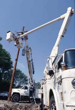
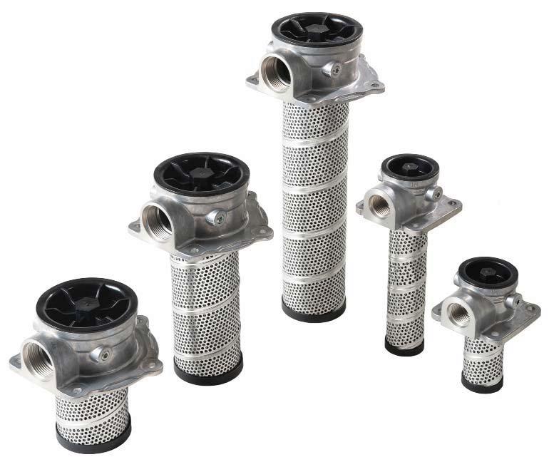
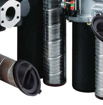
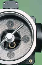
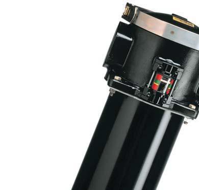
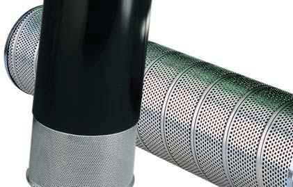
1 12AT/5AT Series Spin-On Filters Applications for Spin-On Filters Mobile Equipment Hydrostatic Drives Industrial Power Units Reservoir Breathers Often, economic conditions dictate what type of filter is used on a piece of equipment. When costs are tight, you need a filter that is inexpensive, yet uncompromising in performance and quality. Parker's spin-on filters fit that need. They are built to fit demanding design parameters in today's mobile and industrial equipment. No compromising. Mounting 2 or 6 hole pattern for flexibility Indicator Gauge Shows at a glance when the cannister needs changing Ports Both NPT and SAE straight thread available Disposable Cannister No mess, oil is contained inside Easy to handle Single and double lengths for longer life Interchangeability Parker cannisters fit many competitors' heads. Contact Hydraulic Filter Division for part numbers TYPICAL LOCATIONS RETURN RETURN SUCTION BREATHER OFFLINE 2
2 12AT/5AT Series Spin-On Filters Media Code Typical Element Performance: 12AT Filter Media Beta Ratios Particle Size/Efficiency 25C Cellulose B 25 =2 25 / 5% 1C Cellulose B 1 =2 1 / 5% 3C Cellulose B 3 =2 3 / 5% 2B Microglass B 2 =75 2 / 98.7% 1B Microglass B 1 =75 1 / 98.7% Actual results are dependent on system flow rates, fluid viscosities, and other parameters. Media Code Typical Element Performance: 5AT Filter Media Beta Ratios Particle Size/Efficiency 25C Cellulose B 25 =2 25 / 5% 1C Cellulose B 1 =2 1 / 5% 3C Cellulose B 3 =2 3 / 5% 2B Microglass B 2 =75 2 / 98.7% 1B Microglass B 1 =75 1 / 98.7% 1C-2 Cellulose B 1 =2 1 / 5% 2B-2 Microglass B 2 =75 2 / 98.7% 1B-2 Microglass B 1 =75 1 / 98.7% 3B-2 Microglass B 3 =75 3 / 98.7% Actual results are dependent on system flow rates, fluid viscosities, and other parameters. Beta Rating Efficiency at (X) Particle Size Bx = % Bx = % Bx = % Bx = % Bx = % AT ASSEMBLY 15 SUS 3C 1C 25C AT-1 ASSEMBLY 15 SUS 3C 2B 25C 1B 1C (PSI) PRESSURE DROP (BAR) (PSI) PRESSURE DROP (BAR) (GPM) FLOW (LPM) (GPM) FLOW (LPM) (PSI) PRESSURE DROP (BAR) AT ASSEMBLY 15 SUS 1B 2B (PSI) PRESSURE DROP (BAR) AT-2 ASSEMBLY 15 SUS 3B 1B 2B 1C (GPM) FLOW (LPM) (GPM) FLOW (LPM)
 Element Collapse Rating: 1 psid minimum Element Condition Indicators: Gauge: Color coded 15/25 psi Gauge: Color coded vacuum Pressure Switch:")
 TORQUE TO 2-3 TURNS FROM FINGER TIGHT 27.")
3 12AT/5AT Series Spin-On Filters Installation and Specification Data Model 12AT Pressure Ratings: Maximum Allowable Operating Pressure (MAOP): 15 psi (1.3 bar) Design Safety Factor: 2.5:1 Operating Temperatures: -4ºF to 225ºF (-4ºC to 17ºC) Element Collapse Rating: 1 psid minimum Element Condition Indicators: Gauge: Color coded 15/25 psi Gauge: Color coded vacuum Pressure Switch: Normally open 2 +/- 2 psi 5 24 VDC Vacuum Switch: Normally open 5" +/- 1" Hg VAC Filter Material: Head: Aluminum Cannister: Low Carbon Steel Shipping Weights (approximate): 1.6 lbs MAX Linear Measure: millimeter inch ¼ - 2 UNC x.31 MIN THREAD DEPTH 2-TOTAL OPTIONAL 1/8-27 NPT GAUGE PORT (4 PLACES) TORQUE TO 2-3 TURNS FROM FINGER TIGHT INLET OUTLET PORTS (BOTH ENDS) ¾"-14 NPTF OR ¾" SAE MAX Drawings are for reference only. Contact factory for current version MINIMUM.62 REMOVAL CLEAR- ANCE 4
 Element Collapse Rating: 1 psid minimum Element Condition Indicators: Gauge: Color coded 15/25 psi Gauge: Color coded vacuum Pressure Switch:")
: Single length: 3.7 lbs. Double length: 5.3 lbs.")
4 12AT/5AT Series Spin-On Filters Installation and Specification Data Model 5AT Pressure Ratings: Maximum Allowable Operating Pressure (MAOP): 15 psi (1.3 bar) Design Safety Factor: 2.5:1 Operating Temperatures: -4 F to 225 F (-4 C to 17 C) Element Collapse Rating: 1 psid minimum Element Condition Indicators: Gauge: Color coded 15/25 psi Gauge: Color coded vacuum Pressure Switch: Normally open 2 +/- 2 psi 5 24 VDC Vacuum Switch: Normally open 5" +/- 1" Hg VAC Filter Material: Head: Aluminum Cannister: Low Carbon Steel Shipping Weights (approximate): Single length: 3.7 lbs. Double length: 5.3 lbs. Linear Measure: millimeter inch OPTIONAL 1/8-27 NPT GAUGE PORT (4 PLACES) TORQUE TO 5-6 INCH POUNDS Ports: (both ends) 1¼"-11½" NPTF or 1¼" SAE-2 Drawings are for reference only. Contact factory for current version. 5
. A pipe flange, weld collar, etc. may be used to connect the cannister adapter kit to the reservoir.")


5 12AT/5AT Series Spin-On Filters Reservoir Breather Assemblies 12AT and 5AT Sizing Select the proper size cannister for the maximum rate of reservoir draw down or air exchange rate. As a rule of thumb, clean pressure drop should be limited to.18 psid (5" H 2 O). A pipe flange, weld collar, etc. may be used to connect the cannister adapter kit to the reservoir. Make sure that air is not able to leak around the adapter. When mounting on the side of the reservoir, make sure the installation is above the surface of the fluid. Recommended cannister change out is after 5 hours of operation. More frequent replacement may be required when operated in heavily contaminated areas such as grinding operations, primary metal mills, and on mobile equipment. Under such conditions, increase replacement frequency to every 25 hours. Model Air Rating* Element Adapter Kit 12AT-3C 1 micron AT-1C 2 micron AT-25C 5 micron AT-3C 1 micron AT-1C 2 micron AT-25C 5 micron * 99% Removal efficiency for particles larger than the stated size in air. Graphs are for 3C cannisters only. Total pressure drop across cannister, adapter, and pipe may be found by adding pressure drops below: + 1.5% for each inch of 12AT adapter or 3/4" pipe used. + 3.% for each 3/4" elbow used. + 1.% for each inch of 5AT adapter or 1-1/4" pipe used. + 2.% for each 1-1/4" elbow used. TYPICAL INSTALLATIONS MOUNTED ON TOP OR SIDE OF RESERVOIR ALLOW 1.25" FOR CANNISTER REMOVAL CLEARANCE DIFFERENTIAL PRESSURE (IN H 2 O) AT 5AT DIFFERENTIAL PRESSURE (PSI) AT 5AT AIR FLOW (SCFM) OIL LEVEL CHANGE RATE (GPM)


6 12AT/5AT Series Spin-On Filters Filter Service Filter cannisters need to be replaced when the pressure gauge reads the filter bypass setting. For example, if a 12AT filter has a 25 psi bypass valve, it needs to be replaced when the pressure gauge reads 25 psi. If no indicator of any kind is used, replace the cannister after the first 5 hours of operation, and every 25 hours thereafter. More frequent replacement could be required depending on operating conditions. When servicing a 12AT or 5AT filter, use the following procedure: A. Shut down the main system and release pressure in the filter line. B. Unthread the cannister and discard it along with the accompanying seal. A strap wrench may be required. C. Apply a small amount of lubricant to the new cannister seal. D. Install the new cannister and hand tighten 3/8 to 1/2 turn after gasket makes contact with head. Accessory Parts List 12AT 5AT Gauge - 15 psi Gauge - 25 psi Pressure switch-25 psi Vacuum switch Breather adapter kit Vacuum gauge Replacement Cannisters Media 12AT 5AT 5AT-2 25C N/A 1C C N/A 2B B B N/A Indicator Gauge (15 PSI) Indicator Gauge (25 PSI) /8-27 NPTF /8 NPT THREAD Vacuum Switch Linear Measure = inches mm Pressure Switch 7
7 12AT/5AT Series Spin-On Filters How To Order Select the desired symbol (in the correct position) to construct a model code. Example: BOX 1 BOX 2 BOX 3 BOX 4 BOX 5 BOX 6 BOX 7 BOX 8 5AT 2 1C N 25 DD N BOX 1: Seals None Buna BOX 2: Basic Assembly 12AT Spin-on (¾" nom.) 5AT Spin-on (1¼" nom.) BOX 4: Cannister Media 25C* Cellulose 1C Cellulose 3C* Cellulose 2B Microglass 1B Microglass 3B ** Microglass * Not available in 5AT-2 ** Not available in 12AT BOX 7: Ports 12AT BB MM 5AT DD OO 3/4" NPTF SAE /4" NPTF SAE-2 BOX 3: Length None Single length cannister 2 Double length cannister (5AT only) BOX 5: Indicator N None BOX 6: Bypass Setting psid psid 3 3 psid X No bypass BOX 8: Gauge Port Location N None H Inlet and outlet, both sides (all ports drilled and tapped) NOTE: Gauges must be ordered separately. Please note the bolded options reflect standard options with a reduced lead-time. Consult factory on all other lead-time options. 8


8 PT Series Tank Top Filters 9


9 PT Series Applications Together we can Preserve the environment. Minimize waste and promote energy efficiency. Achieve worldwide filtration solutions. Build global confidence. Redefine new limits. Forge ahead with advanced technology. Keep contamination under control. Reduce maintenance costs. Enhance total system reliability. Focus on customer satisfaction. Reach optimum potential. Drill to greater depths. engineer your success. The new PT series filter is available in two diameters and three lengths for flow ranges from 5-5 gpm. The PT2 and PT4 filter cartridges utilize Microglass media in 2, 5, 1 and 2 microns for the industry s best particle removal efficiency and retention. This unique design simply threads into a ported weld ring or flange, which can be bolted to a metal reservoir. The disposable filter cartridge is a single-piece construction, which incorporates the nylon cover and integral 25 psi bypass valve. The flow path is inside-out and requires no special tools for service. This concept assures minimal installation costs with the least space requirements for return line applications. Typical Applications Turf Maintenance Material Handling Aerial Lifts Fan Drive The PT Series filter combines high efficiency Microglass filtration with low cost installation featured in a new patented element design. 1


10 PT Series Features Easy element assembly removal 2 Unique high flow top end cap 4 3 Lightweight cast aluminum head 4 Patented filter element assembly 5 Bowl-less, inside-out flow Downstream element support with no aeration design Solid bottom endcap with integrated bypass valve Low profile tank top design


11 PT Series Patented Filter Element Premium original equipment performance every time Tank Top, Bowl-Less Design Reduces weight Significant cost savings over filters with bowls Bottom Endcap Integrated Bypass Valve New bypass valve with every element change Insures reliable performance Inside-Out Element Flow Path Contamination contained within the element No system contamination during element servicing No Aeration Design Oil cascades down the perforated outer support core No system aeration High Flow, Low Pressure Drop Top Endcap Design Long element life Lower maintenance costs Premium Microglass Media Superior dirt holding capacity and efficiency Less maintenance and downtime 12
 2 1 2 3 4 5 6 7 Capacity grams 1 Flow vs. Pressure Loss* LPM 1 2 3 4 5 6 25 2 1.5 PSID 15 1 1. BAR 5.5 5 1 15.")
12 PT Series PT2-1 Element Performance Beta Rating 1 Efficiency Efficiency % PSID 1 Capacity BAR Q 5Q 1Q 2Q s Q 5Q 1Q 2Q Micron Size (c) Capacity grams 1 Flow vs. Pressure Loss* LPM PSID BAR GPM Results typical from Multi-pass tests run per test standard ISO 1 gpm to 1 psid terminal - 1 mg/l BUGL. Refer to Appendix on pages for relationship to test standard ISO *Note: Pressure drop calculations are based on SAE-12 porting. 13
13 PT Series PT2-2 Element Performance PSID 1 Capacity BAR Q 5Q 1Q 2Q Capacity grams 1 Flow vs. Pressure Loss* LPM PSID BAR GPM Results typical from Multi-pass tests run per test standard ISO 15 gpm to 1 psid terminal - 1 mg/l BUGL. Refer to Appendix on pages for relationship to test standard ISO *Note: Pressure drop calculations are based on SAE-12 porting. 14
14 PT Series PT4-1 Element Performance PSID 1 Capacity BAR Q 5Q 1Q 2Q Capacity grams Flow vs. Pressure Loss* LPM PSID BAR GPM. Results typical from Multi-pass tests run per test standard ISO 15 gpm to 1 psid terminal - 1 mg/l BUGL. Refer to Appendix on pages for relationship to test standard ISO *Note: Pressure drop calculations are based on SAE-16 porting. 15
15 PT Series PT4-2 Element Performance PSID 1 Capacity BAR Q 5Q 1Q 2Q Capacity grams Flow vs. Pressure Loss* LPM PSID.5 BAR GPM. Results typical from Multi-pass tests run per test standard ISO 3 gpm to 1 psid terminal - 1 mg/l BUGL. Refer to Appendix on pages for relationship to test standard ISO *Note: Pressure drop calculations are based on SAE-16 porting. 16

16 PT Series PT4-3 Element Performance PSID 1 Capacity BAR Q 5Q 1Q 2Q Capacity grams Flow vs. Pressure Loss* LPM PSID.5 BAR GPM. Results typical from Multi-pass tests run per test standard ISO 45 gpm to 1 psid terminal - 1 mg/l BUGL. Refer to Appendix on pages for relationship to test standard ISO *Note: Pressure drop calculations are based on SAE-16 porting. 17
17 PT Series Specifi cations - PT2 Maximum Allowable Operating Pressure (MAOP): 15 psi ( 1.3 bar) Element Burst Rating: 15 psid Operating Temperatures: Buna: -4 F (-4 C) to 225 F (17 C) Materials: Tank Flange: aluminum Endcaps: nylon Drawings are for reference only. Contact factory for current version. 18
18 PT Series Specifi cations - PT4 Maximum Allowable Operating Pressure (MAOP): 15 psi ( 1.3 bar) Element Burst Rating: 15 psid Operating Temperatures: Buna: -4 F (-4 C) to 225 F (17 C) Materials: Tank Flange: aluminum Endcaps: nylon Drawings are for reference only. Contact factory for current version BUTTRESS 1/8-27 PTF 2 PLC'S REF. Ø4.6 PORT OPTIONS - SEE TABLE /16 (24MM) HEX TORQUE 2-24 IN-LBS Ø3.33 THRU. HOLE O-RING A A.9 DIA FLAT 5 PLC'S 6.2±.6 SINGLE 9.79±.6 DOUBLE `.6 TRIPLE n.345 ON A Ø5.5 B.C. 5 PLC'S EQ. SPACED 1/8-27 PTF 2 PLC'S.4 MIN CLEARANCE FROM TANK BOTTOM Ø3.9 SECTION A-A 19
 941423 PT2 DIE CAST SAE-16 (1.")
19 PT Series PT2 Parts List INDEX PART DESCRIPTION PART NUMBER 1 PT2-1-2Q-25 psid bypass PT2-1-5Q-25 psid bypass PT2-1-1Q-25 psid bypass PT2-1-2Q-25 psid bypass PT2-2-2Q-25 psid bypass PT2-2-5Q-25 psid bypass PT2-2-1Q-25 psid bypass PT2-2-2Q-25 psid bypass PT2 DIE CAST SAE-12 ( UN-2B) PT2 DIE CAST SAE-16 ( UN-2B) PT2 DIE CAST 3/4 NPT ( NPTF-1) PT2 DIE CAST 1 NPT ( NPTF-1) PT2 DIE CAST G3/4 BSPF PT2 DIE CAST G1 BSPF O-RING /8-27 PIPE PLUG /8-27 PRESSURE GAUGE /8 NPT THREAD Linear measure = inches mm Pressure Switch (926923) 2

20 PT Series PT4 Parts List INDEX PART DESCRIPTION PART NUMBER 1 PT4-1-2Q-25 psid bypass PT4-1-5Q-25 psid bypass PT4-1-1Q-25 psid bypass PT4-1-2Q-25 psid bypass PT4-2-2Q-25 psid bypass PT4-2-5Q-25 psid bypass PT4-2-1Q-25 psid bypass PT4-2-2Q-25 psid bypass PT4-3-2Q-25 psid bypass PT4-3-5Q-25 psid bypass PT4-3-1Q-25 psid bypass PT4-3-2Q-25 psid bypass PT4 DIE CAST SAE-16 ( UN-2B) PT4 DIE CAST SAE-2 ( UN-2B) PT4 DIE CAST 1 NPT ( NPTF-1) PT4 DIE CAST 1 1/4 NPT ( NPTF-1) PT4 DIE CAST G1 BSPF PT4 DIE CAST G1 1/4 BSPF O-RING /8-27 PIPE PLUG /8-27 PRESSURE GAUGE /8 NPT THREAD Linear measure = inches mm Pressure Switch (926923) 21
21 PT Series How to Order Select the desired symbol (in the correct position) to construct a model code. Example: BOX 1 BOX 2 BOX 3 BOX 4 BOX 5 BOX 6 BOX 7 BOX 8 PT2 1 1Q B G G S16 1 BOX 1: Filter Series 1 PT2 Tank top filter PT4 Tank top filter BOX 2: Element Length 1 Single 2 Double 3 Triple (Avail. on PT4 only) Consult factory for additional element lengths BOX 3: Media Code 2Q Microglass III, 2 micron 5Q Microglass III, 5 micron BOX 4: Seals B Nitrile (NBR) V Fluorocarbon (FKM) BOX 5: Indicator P Port plugged G Pressure Gauge, 25 psi S Pressure Switch BOX 6: Bypass Pressure Setting G 25 PSI (1.7 bar) BOX 7: Ports PT2 G12 G¾ BSPP G16 G1 BSPP N12 ¾ NPT N16 1 NPT S12 SAE-12 S16 SAE-16 G16 G2 N16 N2 S16 S2 PT4 G1 BSPP G1¼ BSPP 1 NPT 1¼ NPT SAE-16 SAE-2 1Q 2Q Microglass III, 1 micron Microglass III, 2 micron BOX 8: Options 1 None W 2 Steel weld ring Notes: 1. The filters include the element you select already installed. 2. When W is selected in Box 8, the PT2 port options are N12 and S12 ; the PT4 port options are N16 and S16. Please note the bolded options reflect standard options with a reduced lead-time. Consult factory on all other lead-time options. Global products as identified are offered worldwide through all Parker locations and utilize a common ordering code. 22


22 KLT and KLS Series Tank Top Return Line Filters 23


23 KLT/KLS Series Tank Top Return Line Filters Applications for KLT and KLS Filters Mobile Equipment Construction, Refuse Industrial Power Units Machine Tool Oil Field Parker s new KLS /KLT Tank Top Return Line Filters are ideally suited for Mobile and Industrial high to medium flow return applications, from 3 to 12 GPM. This cost-effective, in-tank filter series provides maximum flow and dirt holding capacity for longer filter element life in a simple, easy-toinstall-and-service assembly. The generous element size with extensive media area ensures continuous filtration during cold start up conditions. The inside-to-out flow path with closed bottom provides additional assurance that all contaminants remain captured during element service removal. The filters have a pressure rating of 15 psi static, a temperature range of -4 F to 225 F, and are available in a wide range of high-efficiency Microglass III media in 2, 5, 1 and 2 micron for all system cleanliness requirements. Bypass valves are built into the element to ensure further performance integrity. A new bypass is provided with each element change. This rugged design meets the needs for the demanding applications in mobile off -highway and onhighway applications for construction equipment, logging, refuse vehicles, mining, oil and gas recovery, marine, and industrial power units. Feature Advantage Benefit Tank top mounted filter Saves space and reduces mounting hardware Lower cost, easy to integrate KLS model directly retrofits competitive housing Two-piece head and element construction perforated with metal outer wrap High efficiency Microglass media maximizing filtration area Element design includes intergral disposable bypass valve with closed bottom end cap Magnetic prefiltration Fill and gauge ports No bowl required Provides excellent flow diffusing, eliminating aeration Combines high particle capture efficiency with high dirt holding capacity and lower P New bypass with each element change Ensures captured contaminants are removed with each element change Removes large ferrous contaminants Add fluid through high performance filter media Gauge ports allow for added instrumentation 24 Reduced cost and assembly weight Improved performance Cleaner fluids, longer lasting with fewer service intervals Continuous filtration for cold start ups Lower operating costs Ensures reliable bypass performance No leakage Cleaner fluids reduce risk for contamination during service Extends element life Visual indication of component wear Initial fluid integrity extends system component life Monitor element life
24 KLT/KLS Series Specifi cations Pressure Ratings: Maximum Allowable Operating Pressure (MAOP): 15 psi (1.3 bar) Operating Temperatures: -4 F (-4 C) to 225 F (17 C) Element Burst Rating: 15 psid (1.3 bar) Filtration Rating: 2, 5, 1 & 2 Microns at Beta > 2 Element Condition Indicators: Gauge: -6 psi color coded Switch: SPDT 24 VDC and 25 VAC Materials: Head & Cover: Cast Aluminum Alloy Bypass Valve: Nylon Filter Media: Microglass III Element End Caps: Nylon Weights (approximate): KLT lbs. (1.36 kg) KLT lbs. (1.81 kg) KLT(S) lbs. (3.63 kg) KLT(S) lbs. (4.54 kg) KLT Weld Plate Drawings B 3.4 (86) ¼ NPT THREAD B ½ NPT CONDUIT CONNECTION 18. (457) WIRE LEADS COMMON BLACK N.O. : RED N.C. : GREEN THREAD A 18 TO 22 PSI (YELLOW FIELD) 1.89 (48) 22 TO 6 PSI (RED FIELD) 1.6 (27) C 2.8 (53).55 (14) SQ. D HOLE IN RESERVOIR TO 18 PSI (GREEN FIELD) ¼ NPT THREAD Linear Measure: inch (mm) Dimension KLT Filter Model KLT-2/KLT-4 KLT-7/KLT-8 A 5/16-18 UNC-2A 3/8-16 UNC-2A B 5.33 (135) 7.15 (182) C 1. (25) 1. (25) D 4.5/3.75 (114/95) 6.25/5.5 (159/14) Drawings are for reference only. Contact factory for current version. 25
25 KLT Series Dimensional Drawings KLT 2 / KLT 4 KLT 7 / KLT (68) 3.54 (9) TORQUE: 3 FT-LB (4 N-m) TORQUE: 7 FT-LB (1 N-m) 4.72 (12) TYP SAE-16 STRAIGHT THREAD O-RING PORT 6.54 (166) TYP. SAE-24 STRAIGHT THREAD O-RING PORT.35 (9) DIA. MOUNTING HOLES (4 PLACES) ON 4.96 (126) B.C. RECOMMENDED HEAD TO TANK TORQUE: 11 FT-LB (15 N-m).43 (11) DIA. MOUNTING HOLES (4 PLACES) ON 6.89 (175) B.C. RECOMMENDED HEAD TO TANK TORQUE: 3 FT-LB (4 N-m) C MIN. SERVICE CLEARANCE ¼ NPT PLUGGED GAUGE PORT(S) (3 PLACES) C MIN. SERVICE CLEARANCE 3.66 (93) ¼ NPT PLUGGED GAUGE PORT(S) (3 PLACES) 2.83 (72) 1.42 (36) 1.1 (28) D D RESERVOIR CUTOUT DIAMETER RESERVOIR CUTOUT DIAMETER L L Linear Measure: inch (mm) Drawings are for reference only. Contact factory for current version. Dimensions KLT Filter Model KLT-2 KLT-4 C 5.75 (146) 9.5 (241) L 4.16 (16) 7.75 (197) D 3.6 (93) 3.56 (9) Dimensions KLT Filter Model KLT-7 KLT-8 C 13. (33) (489) L (291) 17.7 (45) D 5.36 (136) 5.26 (133) 26
26 KLT Series Dimensional Drawings KLS 7 / KLS (86).43 (11) DIA. MOUNTING HOLES (4 PLACES) ON 6.25 (158.8) B.C. RECOMMENDED HEAD TO TANK TORQUE: 3 FT-LB (4 N-m) 6.76 (172) TORQUE: 12 FT-LB (16 N-m) C MIN. SERVICE CLEARANCE SAE-24 STRAIGHT THREAD O-RING PORTS (BOTH SIDES) 3.62 (92) 1.62 (41) ¼ NPT PLUGGED GAUGE PORTS (2 PLACES) D RESERVOIR CUTOUT DIAMETER L Linear Measure: inch (mm) Dimensions KLS Filter Model KLS-7 KLS-8 C 13. (33) (489) L (291) 17.7 (45) D 5. (127) 4.8 (122) Drawings are for reference only. Contact factory for current version. 27


27 KLT Series Dimensional Drawing KLT with 2 Port 5/16-18 UNC-2B TAP THRU. 4 PLC'S 1/4" NPT 3 PLC'S 3.62 REF REF REF..844 REF REF REF. Ø PLC'S EQUALLY SPACED 1/2-13 UNC-2B Drawings are for reference only. Contact factory for current version. 28
28 KLT Series KLT-2 Element Performance Beta Rating 1 Efficiency Efficiency % 2Q 5Q 1 1Q Q Micron Size (c) Multipass tests 15 gpm to 25 psid terminal - 1 mg/l BUGL Flow vs. Pressure Loss 29
29 KLT Series KLT-4 Element Performance Beta Rating 1 Efficiency Efficiency % 2Q 5Q 1 1Q Q Micron Size (c) Multipass tests 3 gpm to 25 psid terminal - 1 mg/l BUGL Flow vs. Pressure Loss 3
30 KLT/KLS Series KLT/KLS-7 Element Performance Beta Rating 1 Efficiency Efficiency % 2Q 5Q 1 1Q Q Micron Size (c) Multipass tests 5 gpm to 25 psid terminal - 1 mg/l BUGL Flow vs. Pressure Loss 31
31 KLT/KLS Series KLT/KLS-8 Element Performance Beta Rating 1 Efficiency Efficiency % 2Q 5Q 1 1Q Q Micron Size (c) Multipass tests 7 gpm to 25 psid terminal - 1 mg/l BUGL Flow vs. Pressure Loss 32
32 KLT/KLS Series KLT with 2 Port - Element Performance Efficiency Beta Rating Efficiency % 1 2Q 1 5Q 1Q Q Micron Size (c) Flow vs. Pressure Loss LPM SUS 16. 2Q PSID BAR 5Q Q Q GPM 33
33 KLT and KLS Series Operating and Maintenance Instructions A. Mounting 1. Standard mounting. a. Cut proper size hole in the top of the reservoir. b. Drill holes for studs within the proper bolt circle. c. Set the filter into the cutout hole and secure with proper size bolts, nuts and lock washers. d. Torque nuts in accordance with drawing. 2. Mounting procedure using weld plate. a. Rough cut proper size hole in the top of reservoir. b. Weld the weld plate concentric to the rough cut hole. c. Mount the filter onto the studs and secure with nuts and lock washers. d. Torque nuts in accordance with drawing. 3. Utilize proper fittings. B. Start-Up 1. Check for and eliminate leaks upon system start-up. 2. Check differential pressure indicator, if installed, to monitor element condition. C. Service 1. An element must be serviced when the indicator indicates service is required. NOTE: If the filter is not equipped with an indicator, the element should be serviced according to machine manufacturer s instructions Parts List Index Part Number Quantity 1 Cover Assembly (Includes Cover o-ring) KLT2/KLT KLT7/KLT KLS7/KLS Cover o-ring KLT2/KLT4, Nitrile N KLT2/KLT4, FKM V KLT7/KLT8, Nitrile N KLT7/KLT8, FKM V KLS7/KLS8, Nitrile N KLS7/KLS8, FKM V Element (see How to Order page) 4 Filter Head (Includes gauge plugs & studs) KLT2/KLT4 (S16) KLT7/KLT8 (S24) KLS7/KLS8 (S24) KLS7/KLS8 (2 Flange) Tank Gasket KLT2/KLT4 18x98x5.5B 1 KLT7/KLT8 152x136x6B 1 KLS7/KLS8 (O-Ring) N72355 (C.F.) 1 Not Shown Weld Plate KLT2/KLT KLT7/KLT Not Shown Pressure Switch NS-1C-19R/EL 1 Not Shown Pressure Gauge C.F. = Consult Factory D. Servicing Dirty Element 1. Shut system down to assure that there is NO PRESSURE OR FLOW into the filter housing. 2. Remove the filter cover. 3. Remove and discard the contaminated element cartridge. E. Before Installing a New Element Cartridge 1. Clean the magnetic core with a lint-free cloth. 2. Check all seals and replace if necessary. F. To Install a New Element Cartridge 1. Lubricate all seals. 2. Mount new filter cartridge. 3. Re-install the cover. 4. Torque the cover nuts per drawing. Perform procedures B1 and B2 to ensure no leaks are present. 34
34 KLT and KLS Series How to Order Select the desired symbol (in the correct position) to construct a model code. Example: BOX 1 BOX 2 BOX 3 BOX 4 BOX 5 BOX 6 BOX 7 BOX 8 KLT 7 1Q B P G S24 1 BOX 1: Filter Series KLT Single port return-line filter KLS Dual port return-line filter (-7 and -8 models only) BOX 2: Filter Model 2 3 GPM (115 l/m nominal flow) 4 5 GPM (19 l/m nominal flow) 7 1 GPM (38 l/m nominal flow) 8 12 GPM (455 l/m nominal flow) BOX 3: Media Code 2Q Microglass III, 2 micron 5Q Microglass III, 5 micron 1Q Microglass III, 1 micron 2Q Microglass III, 2 micron WR Water Removal BOX 4: Seals B Nitrile (NBR) V Fluorocarbon *NOTE: Nitrile tank gasket always supplied. BOX 5: Indicator P No indicator; plugged pressure port(s) G Pressure gauge, -6 psig S Pressure switch BOX 6: Bypass Pressure Setting G 25 psid (1.7 bar) BOX 7: Ports KLT-2/4 S16 SAE-16 (1 5/16-12) KLT-7/8 S24 SAE-24 (1 7/8-12) N24 1 1/2 NPT Y32 2 Code 61 Flange Face KLS-7/8 S24 2 x SAE-24 (1 7/8-12) N24 2 x 1 1/2-NPT BOX 8: Options 1 None TP Weld plate (KLT only) Replacement Elements Element Nitrile Fluorocarbon Code Q Q Q Q Q Q Q Q Q 1Q Q 93697Q Q Q Q Q Q 93728Q 5Q Q Q Q Q Q Q Q Q 2Q Q Q Q Q Q 93727Q Q Q WR C.F. C.F. C.F. C.F. C.F. = Consult Factory Global products as identified are offered worldwide through all Parker locations and utilize a common ordering code. 35


35 Moduflow Low Pressure Filters Series 36


36 Moduflow Applications Series - Power Unit Fabrication - Off-line Filter Loops - Mobile Equipment The Moduflow filter is widely considered the most versatile filter available on the market. The patented end cap minimizes turbulence and pressure loss through the filter, improving system performance. The newly designed closed bottom elements for the RFP and ILP models insures all contamination remains trapped within the element as the filter is serviced. A wide variety of visual and electrical indicators allows you to know exactly when the element needs to be serviced. There is even a no element indicator that can sense when there is not an element installed in the filter. From top to bottom, the Moduflow filter series provides the high level of filtration and long term dependability so vital to today s hydraulic systems. Parker s new patented Moduflow element was designed with built-in diverter and bypass valve, to meet your application needs. Mounting / Porting Styles RFP Return Filter ILP In-Line Filter RETURN OUT FILTER HEAD IN BOWL TANK BOWL OUTLET PORT 37
 - Integral 35 psi bypass replaced with every element change Element (not visible) -")
37 Moduflow Features Series Flanges - NPT or SAE ¾ to 2 - Lightweight aluminum Cover - Slotted for quick release - Lightweight aluminum Indicators - Visual or electrical - Mounted on either side - Standard no element indication Bowl - Single or double length - Durable steel construction Bypass (not visible) - Integral 35 psi bypass replaced with every element change Element (not visible) - Available in high performance Microglass III media - Single or double length Top access element service Slotted cover Closed bottom elements Feature Advantage Benefit Oil remains in housing Quicker elements change Quick release cover Cap screws remain in housing Removes all contaminant during element service No Spills Reduced maintenance costs Reduced maintenance costs No loose parts to lose No downtime contamination from servicing Visual or electrical indicators Know exactly when to service elements Helps prevent bypass condition No premature disposal Flange face ports Flexible mounting (3/4 to 2 ) Easy plumbing to your system 38
38 Moduflow Series RFP-1 and ILP-1 Element Performance Beta Rating 1 1 2Q Efficiency 5Q 1Q Efficiency % 99.9 PSID 5 4 Capacity 2Q 5Q 1Q 2Q BAR Q Micron Size (c) Capacity grams. Multipass tests 4 gpm to 5 psid terminal - 5mg/L BUGL LPM Flow vs. Pressure Loss LPM SUS 2Q 5Q SUS Empty Housing.6.5 PSID Q 2Q BAR PSID SAE flange BAR GPM GPM 39
39 Moduflow Series RFP-2 and ILP-2 Element Performance Beta Rating 1 1 2Q Efficiency 5Q 1Q Efficiency % 99.9 PSID 5 4 Capacity 2Q 5Q 1Q 2Q BAR Q Micron Size (c) Capacity grams. Multipass tests 8 gpm to 5 psid terminal - 5mg/L BUGL Flow vs. Pressure Loss LPM LPM SUS SUS Empty Housing.6.5 PSID Q 5Q.8.6 BAR PSID BAR 4 1Q 2Q SAE flange GPM GPM 4
 Element Burst Rating: 7 psid (4.")
: Single: 2 lbs. (9.1 kg) Double: 25 lbs. (11.3 kg) Indicators: Visual (optional) Electrical (optional) 15A @ 25VAC /.")
40 Moduflow Specifi cations: RFP, ILP Pressure Ratings: Maximum Allowable Operating Pressure (MAOP): 2 psi (13.8 bar) Design Safety Factor: 2:1 Rated Fatigue Pressure: 15 psi (1.3 bar) Element Burst Rating: 7 psid (4.8 bar) Filter Materials: Head, Cover, Flanges: die cast aluminum Bowl: steel Operating Temperatures: Nitrile: -4 F to 225 F (-4 C to 17 C) Fluorocarbon: -15 F to 275 F (-26 C to 135 C) Weight (approximate): Single: 2 lbs. (9.1 kg) Double: 25 lbs. (11.3 kg) Indicators: Visual (optional) Electrical (optional) 25VAC 125 VDC Electrical ( D option) 25VAC / 28 VDC Color Coding: White (normally closed) Red (normally open) Black (common) ILP OUTLET OPTIONAL 3-PIN MALE RECEPTACLE Series MINIMUM ELEMENT REMOVAL CLEARANCE Single: Double: Dimensions: mm inch Model A B C D RFP-1 with optional 2 fitting RFP-1 without optional 2 fitting RFP-2 with optional 2 fitting RFP-2 without optional 2 fitting ILP ILP _ _ Drawings are for reference only. Contact factory for current version _ _ N/A N/A A OPTIONAL PORT FLANGE IL & RF INLET Linear Measure: millimeter inch C OPTIONAL BMOUNTING BRACKET OPTIONAL TANK FLANGE (99 OPTION) RFP-1 OUTLET RFP OUTLET D 2-11½ NPTF OPTIONAL FITTING 41
 Element Burst Rating: 7 psid (4.")
 Fluorocarbon: -15 F to 275 F (-26 C to 135 C) Weight (approximate): Single: 55 lbs. (24.9 kg) / Double: 65 lbs. (29.5 kg) Indicators: Visual (optional) Electrical (optional) 15A @ 25VAC /.")

41 Moduflow Series Drawings Specifi cations: DILP Pressure Ratings: Maximum Allowable Operating Pressure (MAOP): 2 psi (13.8 bar) Design Safety Factor: 2:1 Rated Fatigue Pressure: 15 psi (1.3 bar) Element Burst Rating: 7 psid (4.8 bar) Filter Materials: Diverter Valve Assembly: die cast aluminum Check Valve Assembly: die cast aluminum Filter Assembly: see IL2 specifications Operating Temperatures: Nitrile: -4 F to 225 F (-4 C to 17 C) Fluorocarbon: -15 F to 275 F (-26 C to 135 C) Weight (approximate): Single: 55 lbs. (24.9 kg) / Double: 65 lbs. (29.5 kg) Indicators: Visual (optional) Electrical (optional) 25VAC 125 VDC Electrical ( D option) 25VAC / 28 VDC Color Coding: White (normally closed) Red (normally open) Black (common) FILTER SCHEMATIC FILTER BYPASS OUTLET FILTER BYPASS OPTIONAL FLANGE INLET ¼-18 NPT DRAIN VENT CONNECT TO TANK are for reference only. Contact factory for current version Linear Measure: millimeter inch AIR BLEED EACH FILTER ½-13 SHCS TORQUE FT-LB OUTLET SINGLE DOUBLE INLET DRAIN VENT OPTIONAL MECHANICAL INDICATOR Torque (Ft-Lbs) BOTH CHECK VALVES MOVE SAME DIRECTION Approximate handle torque required for changeover System Pressure (psi) BAR PSID DIFF. PRESSURE Typical Flow/Pressure Curves For Duplex Valves (Add to differential pressure of filter assembly for total duplex pressure differential) *Diverter/check valves combined 3 SUS 2 SUS GPM FLOW LP M
42 Moduflow Specifi cations For return line applications (RFP), the fluid returning to the reservoir holds the check valve open. When the system is shut down, the check valve closes automatically. Series Check Valve Flow/Pressure Drop 3. *Check valve pressure drop must be added to assembly pressure drop to get total 2.5 Pressure Loss (psid) Flow (GPM) Linear Measure: millimeter inch RFP SINGLE ELEMENT RFP DOUBLE ELEMENT Drawings are for reference only. Contact factory for current version MAX. O.D OVER WELD (RFP & DOUBLE LENGTH) 43
43 Moduflow Specifi cations Series Lower Cost than many single unit filters. Moduflow Manifold Extended Filter Range Use Model MM Manifold to handle return line flows up to 13 gpm. Rated static pressure: 3 psi Typical burst pressure: 9 psi Easily mounted on ModuFlow High Flows At Low Cost The model MM manifold is designed to extend the flow range of ModuFlow TM Filters when operating with 1 Micron and finer filter media. When mounted to a pair of RFP-2 or ILP-2 filters, this manifold will allow flows up to 13 gpm in return lines (15 fps velocity). Note: The Model MM manifold is not applicable to suction lines due to its pressure drop characteristics. When used with two ModuFlow TM filters, the total cost is often less than a single unit filter rated for 13 gpm flow. Tank-top mounted (Model RFP) filters will require only one manifold on the filter inlet pports. In-line mounted (Model ILPav) filters will require two manifolds, one on the inlet and one on the outlet ports Proven Reliability The rugged design of the Model MM manifold has been proven in demanding mobil equipment applications, At the factory, we have cycle tested the Model MM through the full range of rated flow and pressure to insure reliable service. Parker Filter Division maintains the same high standards in delivery, quality, and service. Considering this, plus features, flexibility, price, and performance, the Model MM manifold is a valuable addition to your fluid power component list. FLOW/PRESSURE CURVE (PSI) DIFF. PRESS. (BAR ) TYPICAL FLOW/PRESSURE CURVES FOR SUS MODEL MM 38B6 Multiple Uses Although designed for manifold ModuFlow TM filters, the Model MM can be used in a variety of applications which require: Splitting flow between components (GPM) INLET FLOW (LPM) Such applications are frequently encountered on mobile equipment, machine tools, and large lubricating systems. In such applications, use of a manifold can often reduce total piping and installation costs. 44
44 Moduflow Specifi cations Series MANIFOLD SPECIFICATIONS Rated Static Pressure, maximum: 2.7 bar (3 psi) Typical Burst Pressure: 62.1 bar (9 psi) Operating Temperature (Buna seals): +121ºC to 4ºC (+25ºF to 4ºF) HOW TO ORDER MANIFOLDS: Part Number Moduflow Manifold Housing Material: ANSI 356-T6 cast aluminum Approximate Shipping Weight: 3.6 kg (8 lbs) Porting: See Options Below Order Screws and O-Rings Seperately: Inlet & outlet screws (12 required): Order P/N 9228 Outlet port o-rings (2 required): Nitrite: Order P/N N72228 Fluorocarbon: Order P/N V92228 * Tank-top mounted RFP filters will require one manifold on filter inlets: in-line mounted ILP filters will require two manifolds on both inlets and outlets. 12.7mm mm mm mm 3.5 INSTALLATION DIMENSIONS 155.6mm mm mm 3.62 (TORQUE SCREWS TO FT-LBS) 42.9mm mm mm 3.62 (TORQUE SCREWS TO FT-LBS) 66.8mm 2.63 VIEW AT C-C 273.8mm 1.78 STANDARD OUTLET, 2 PLS 2- SAE 4-BOLT FLANGE WITH O-RING GROOVE Drawings are for reference only. Contact factory for current version. C C TOLERANCES To one decimal place: To two decimal places: 3.mm.12.8mm.3 To three decimal places:.4mm.15 Linear Measure: Millimeter Inch 45
 8.7.344 DIA. THRU PLACES 161.5 6.5 122.9 4.84 6 TYP 7.9.31 114.3 4.")

45 Moduflow Accessories Series Linear Measure: millimeter inch M OPTION-VISUAL INDICATOR, NO ELEMENT WARNING OPTIONAL MOUNTING BRACKET (92494) DIA. THRU PLACES TYP R DIA. THRU 4 PLACES DIA. THRU TYP Drawings are for reference only. Contact factory for current version E OPTION-ELECTRICAL INDICATOR 46
46 Moduflow Parts List Series Size Flange Kits (flange, 4 bolts, o-ring) Part Number Code Buna Fluorocarbon ¾ inch NPTF YB inch NPTF YC ¼ inch NPTF YD ½ inch NPTF YE inch NPTF YF SAE - 12 YM SAE - 16 YN SAE - 2 YO SAE - 24 YP BLANK FLANGE RFP / ILP / DILP Replacement Elements Nitrile Seals Fluorocarbon Seals Media New Single Replaces Old Single New Double Replaces Old Double New Single Replaces Old Single New Double Replaces Old Double 2Q Q Q Q Q 93741Q Q 93745Q Q 5Q Q Q Q Q 93742Q 93269Q 93746Q Q 1Q Q Q Q Q 93743Q Q 93747Q Q 2Q Q Q 9374Q Q 93744Q Q 93748Q Q WR


47 Moduflow Parts List Series Index Part No. Quantity 1 Screws, Nameplate Name Plate, Unstamped Cover Screws, 5/16-18 UNC x Bowl Screws, 5/16-18 UNC x Cover, Without nameplate O-Ring, cover Nitrile... Fluorocarbon... 7 Element Seal Nitrile... Fluorocarbon... Filter Assembly Exploded View 6 N7235 V Element... Refer to Table 1 9 Head, Machined only... 2 SAE Flange 1½ SAE Flange 1½ NPTF 1 Bowl, Select desired model ILP-1... ILP-2... RFP-1... RFP-1 with 2 inch NPTF fitting... RFP-2... RFP-2 with 2 inch NPTF fitting Index Part No. Quantity 11 Check Valve Assy Flange Kits... O-Ring 13 Plug Kit, Fastener, self-sealing, o-ring seal included with fastener 14 Indicator Electrical 35 psid psid, 3-pin male receptacle... Gasket O-Ring 15 Indicator Visual 35 psid 4-band... Bracket, Inline mounting... Indicator Kit, Remote mount Changeover Valve Assy., Duplex 17 Not Shown Not Shown Check Valve Assy., Duplex... Drain Plug, SAE-24 for RFP model Nitrile... Fluorocarbon... O-Ring between tank and bowl Refer to Table V V N72265 Optional 2 2 Optional Optional Optional Optional Optional Drawings are for reference only. Contact factory for current version. 48
48 Moduflow How to Order Series BOX 1 BOX 2 BOX 3 BOX 4 BOX 5 BOX 6 BOX 7 BOX 8 ILP 1 1Q B MP 35 Y9Y9 1 BOX 1: Filter Series RFP ILP DILP BOX 2: Element Length Return-line filter, inlet on side outlet on bottom In-line filter In-line duplex 1 Single 2 Double BOX 3: Media Code 2Q 5Q 1Q 2Q WR BOX 4: Seals B E V Microglass III, 2 micron Microglass III, 5 micron Microglass III, 1 micron Microglass III, 2 micron Water Removal Nitrile EPR Fluorocarbon BOX 5: Indicator P M E D Note: First letter of indicator code = left side of filter head when looking into inlet with bowl down; second letter = right side of filter head when looking into inlet with bowl down. BOX 6: Bypass Setting Pressure ports drilled & plugged only; no indicator Visual indicator w/ no element warning Electrical indicator only Electrical indicator only, 3-pin male receptacle psid BOX 7: Port Options Filter Model Inlet / Y9 2 flange face 99 No fitting RFP P9 SAE-24 integral threads Y9 2 flange face Y9 2 flange face 1) First pair of symbols denotes inlet for all filter styles; second pair of symbols denotes outlet. 2) Four symbols required: two for inlet, two for outlet. 3) Unused ports in filters come plugged with a blank flange. 4) See Flange Kits table for port flange options. Flange Kits are ordered separately. F9 2 NPTF F8 External check valve Y9 2 flange face Y9 2 flange face ILP P9 SAE-24 integral threads DILP BOX 8: Options 1 None Outlet / P9 E9 SAE-24 integral threads 1½ NPTF integral threads 49
49 Moduflow TFP Series 3.24 [82.4] Bowl-less Design INLET FLANGE KIT ACCESSORY 1.19 [3.2] 6.62 [168.1] COVER 5/16-18 UNC HEX HEAD COVER SCREW TORQUE TO 16-2 FT-LBS 3.6 [77.8] 3.18 [8.7] 2.47 [62.7] INLET [63.] INLET CONFIGURATION: 2 SAE FLANGE FACE (REF. SAE J518 CODE 61) WITH INTEGRAL SAE-24 (1 7/8-12 UN-2B THREAD) O-RING BOSS PORT (REF. SAE J1926/1) TANK MOUNTING SURFACE (.1 MIN. FLATNESS REQUIRED FOR SEAL) 4.7 [119.4] TANK HOLE RECOMMENDED (5. [127.] MAX ALLOWED) FLANGE SEAL P/N N72251 (SIZE 2-251) [39.6] TFP [545.1] TFP-2.5 [12.7] MIN INSTALLATION CLEARANCE TANK BOTTOM SURFACE BYPASS FLOW DIA TANK MOUNT HOLES 4-TOTAL ON 6.75 BOLT CIRCLE BOTTOM VIEW Features Advantages Shorter port-to-port distance. Direct tank mount capability eliminates need for adaptor flanges and bowl. Standard head incorporates 2 SAE flange face with integral SAE-24 port configuration. Filter head and element 2-piece construction requires no filter bowl. Patented element design with integral bypass valve and inside to out flow path. Provides a smaller footprint and reduced weight. Aluminum die cast head reduces weight and direct tank mount flange reduces installation time and cost. Enables one common head to be used. Simplifies ordering model code. Reduces assembly cost by 25%. 5 Ensures all contaminants remain captured during service. New bypass valve with each element ensures operation reliability.
50 Moduflow How to Order TFP Series BOX 1 BOX 2 BOX 3 BOX 4 BOX 5 BOX 6 BOX 7 BOX 8 TFP 1 1Q B MP 35 C32 1 BOX 1: Series TFP TFPW Box 2: Element Length 1 Single 2 Double Box 3: Media Code 2Q 5Q 1Q 2Q WR Return-line filter Return-line filter anodized for HWHC fluid Microglass III, 2 micron Microglass III, 5 micron Microglass III, 1 micron Microglass III, 2 micron Water Removal BOX 5: Indicator P M E D Pressure ports drilled & plugged only; no indicator Visual indicator w/ no element warning Electrical indicator only Electrical indicator only, 3-pin male receptacle Note: Two letters are required for the indicator code (e.g. MP ) BOX 6: Bypass (2.4 bar) psid BOX 8: Ports C32 BOX 8: Options 1 None 2 SAE flange face/sae- 24 combination inlet port BOX 4: Seals B E V Nitrile EPR Fluorocarbon Media Nitrile TFP-1 Fluorocarbon Replacement Elements Ethylene Propylene Media Nitrile TFP-2 Fluorocarbon 2Q Q 93741Q Q 2Q Q 93745Q Q 5Q Q 93742Q Q 5Q Q 93746Q Q 1Q Q 93743Q Q 1Q Q 93747Q Q 2Q Q 93744Q Q 2Q 9374Q 93748Q Q WR N/A WR N/A Ethylene Propylene 51


51 RF7 Series Low Pressure Filters 52

 - Easy in-tank mounting")

52 RF7 Series Applications - Mobile equipment - Power unit fabricators - Off-line filter loops The Parker RF7 filter is designed for those applications where depend able, yet economical, return line system protection is required. The in-tank mounting design makes the RF7 ideally suited for use by power unit fabricators and mobile equipment manufacturers...or anyone who views equipment space at a premium, but not at the expense of performance. Element Condition Indicator - True pressure differential - Know, at a glance, when to change the filter element - Gauge also available Two-Piece Construction (Head/Tube) - Easy in-tank mounting Diffuser Tube - Disperses return flow below reservoir fluid level - Prevents fluid aeration - Closed bottom provides for even fluid dispersal - Prevents objects from falling into the reservoir during element servicing Bypass Valves - Virtually zero leakage - Multiple valves for high flow Vent - For variable displacement pump applications Cartridge/Element Handle - Easy to remove entire assembly for servicing Bypass Filter Screen - Prevents gross contamination from passing through the filter even during bypass 53 Cover Lock-Band with T Handle - Easy access for servicing - No loose parts to remove and handle - No special tools required for removal

53 RF7 Series Element Features Inside each Parker Filter... a quality Parker Element The important item in a filter assembly is the element. It has to capture and hold contaminants that can damage or stop a machine...while at the same time allowing the required flow of clean fluid so the machine can function properly. There are many ways to design and build an element, and it s easy to produce a low cost element. However, cost is not a good selection criteria... especially when the risk is loss of critical performance. For instance, consider wire mesh reinforcement. Not all filter elements have it. It s used in Parker elements to keep the pleats from collapsing or bunching. If pleats bunch, the effective surface area of the element is reduced, excessive pressure drop develops, and the filter assembly may go into the bypass mode. This condition wastes energy and allows unfiltered fluid flow back into the system, effectively shortening filter life. Gasket Ring Seal - Positive sealing for optimum element efficiency Protective Perforated Cylinder - Necessary for inside-to-outside flow - Prevents media blow out Wire Reinforced Media (Not Visible) - Prevents pleat bunching - Helps prevent media migration - Maintains media efficiency Engineered Element Design - The right combination of pleat depth and number of pleats means lower pressure losses (longer life) - Dirt holding capability is maximized for less frequent element change-out Elements for Every Application - Standard Microglass III media for long life and excellent system protection - Economical cellulose elements also available Features Advantage Benefits Tank mounted design. Saves space and reduces Easy to integrate into system design. hardware requirements. Cover fill port. Allows 1% filtration of all new system oil. Eliminates contamination before it can cause problems. High flow capacity. One filter may handle all return line flows. Cost savings in filters and hardware. Broad range of filter media available including water removal. Inside-to-outside flow through element with a closed bottom end cap. Wire reinforced Microglass III elements. Multipass tested elements (per ANSI/NFPA T R1-199 modified for fine filtration). Complete element performance data disclosure. Choose the proper medium for system parameters. All contamination is trapped inside of element assembly. Rugged construction stands up to abuse of cyclic flows without performance loss. Wire support reduces pleat bunching, keeps pressure drop consistent. Filter performance backed by recognized and accepted laboratory test standards. All pertinent information is provided in an easy-to-compare format. 54 Cost savings by avoiding both over and under filtration. Contamination is not reintroduced into the system during replacement. The reliable filtration provided assures equipment protection, reduces downtime, maximizes element life, and allows the hydraulic system to operate properly. Filters you select have consistent performance levels. Provides an easy guide to proper filter selection.
54 RF7 Series RF7-1 Element Performance Beta Rating 1 Efficiency Efficiency % PSID 5 Capacity BAR Q 5Q 1Q 2Q Q 5Q 1Q 2Q Micron Size (c) Capacity grams. Results typical from Multi-pass tests run per test standard ISO 5 gpm to 5 psid terminal - 1 mg/l BUGL Refer to Appendix on pages for relationship to test standard ISO LPM Flow vs. Pressure Loss LPM PSID Q 5Q 1Q 2Q BAR PSID Empty Housing BAR GPM GPM 55
55 RF7 Series RF7-2 Element Performance Beta Rating 1 1 2Q Efficiency 5Q 1Q Efficiency % 99.9 PSID 5 4 Capacity 2Q 5Q 1Q 2Q BAR Q Micron Size (c) Capacity grams. Results typical from Multi-pass tests run per test standard ISO 8 gpm to 5 psid terminal - 1 mg/l BUGL Refer to Appendix on pages for relationship to test standard ISO LPM Flow vs. Pressure Loss LPM SUS 2Q SUS.6.5 PSID Q 1Q 2Q BAR PSID Empty Housing BAR GPM GPM 56
56 RF7 Series Specifi cations Pressure Ratings: Maximum Allowable Operating Pressure (MAOP): 15 psi (1.3 bar) Design Safety Factor: 3:1 Element Burst Rating: 5 psid (3.4 bar) minimum. Materials: Cast Aluminum Head & Cover Steel Diffuser Tube Steel Clamp Note: Optional v ent f or va ri ab le displacement pump applications ava ila bl e on co v er (not sho wn. ) Operating Temperatures: Nitrile; -4 F to 225 F (-4 C to 17 C) Fluorocarbon; -15 F to 275 F (-26 C to 135 C) Weight (approximate): RF lbs. (15.4 kg) RF lbs. (19 kg) RF RF ELEMENT REMO VA L CLEARANCE INLET (STANDARD) HAND TIGHTEN ONLY Indicators: Visual system pressure type (gauge or pressure switch). Visual pressure differential type. Electrical pressure differential type VDC DIA. MOUNTING HOLES 4 TOTAL EQUALLY SPACED ON DIA. B.C. SECOND INLET (OPTIONAL) SQ MECHANICAL I NDICA TO R (OPTIONAL- LEFT SIDE SHO WN) INLE T MAX MAX MOUNTING GASKET ELECTRICAL INDICATOR (OPTIONAL RIGHT SIDE SHOWN) DIA. VENT HOLE RF RF DIA /2-13 UNC X.81 MIN FULL THD DEPTH 4-PLACES 2" SAE J518 CODE 61 FLANGE FACE DIA /2-13 UNC X.94 MIN FULL THD DEPTH 4-PLACES 2 1/2" SAE J518 CODE 61 FLANGE FACE O UT LE T DIA. Clearance hole in tank reser vo ir to be 7 1/8 IN. + 1/16 IN. DIA. Linear Measure: millimeter inch Dimensions are intended for reference only. Drawings are for reference only. Contact factory for current version. 57
57 RF7 Series Specifi cations Filter Service When servicing an RF7 filter, use the following procedure: A. Stop all flow to the filter. B. Loosen the clamp handle counterclockwise and remove the clamp assembly. C. Remove the filter cover by lifting upward. D. Pull the entire cartridge assembly out by grabbing onto the T handle. E. Unscrew the T handle from the bypass assembly (with mesh screen) and remove the bypass assembly. F. Lift the element over the exposed rod assembly and discard. G. Place a new element over the rod and seat on the bottom. H. Re-attach the bypass assembly to the top of the element. I. Replace the T handle and hand-tighten. J. Firmly place the entire cartridge assembly back into the filter housing. K. Set the cover back on the housing, reattach the clamp assembly and hand tighten the handle Parts List Index Part Number RF7-1 RF7-2 1 Head - Single Inlet 2 SAE Flange Face w/gage ports /2 SAE Flange Face w/gage ports SAE Flange Face w/indicator /2 SAE Flange Face w/indicator Head - Double Inlets 2 SAE Flange Face w/gage ports /2 SAE Flange Face w/gage ports SAE Flange Face w/indicator /2 SAE Flange Face w/indicator Cover Bypass Mount Lipseal Nitrile Fluorocarbon Bypass Valve (6) Screen Screen Retaining Ring T Handle Assembly Clamp Clamp Handle Cover O-Ring Nitrile N72263 N72263 Flourocarbon V72263 V Element (See model code page) 13 Cartridge Rod Assembly Diffuser Tube Assembly Gasket Nitrile Fluorocarbon Nameplate Drivescrew (2) Pressure Gauge Indicators Visual Electrical
58 RF7 Series How to Order BOX 1 BOX 2 BOX 3 BOX 4 BOX 5 BOX 6 BOX 7 BOX 8 RF7 2 1Q MP 25 Y999 1 BOX 1: Seals None F3 BOX 2: Basic Assembly RF7 Nitrile Fluorocarbon In-tank return filter BOX 3: Length 1 Single length 2 Double length BOX 5: Indicator(s) (2 Required) P G S M E (See Note A) Gauge, port plugged Gauge, color coded Pressure switch Visual indicator Electrical indicator Note A: (First letter of indicator code = left side of filter head when looking into inlet with bowl down; second letter = right side of filter head when looking into inlet with bowl down.) BOX 7: Ports Inlet Y9 Z9 Side 2 SAE flange face (Standard) 2½ SAE flange face (Standard) 2Y9 Two Inlets, 18 apart (Optional) 2Z9 Two Inlets, 18 apart (Optional) Outlet 99 No fitting BOX 4: Media Code BOX 6: Bypass Setting BOX 8: Modifications 2Q Microglass III psid 1 None 1Q Microglass III 5Q Microglass III 2Q Microglass III 1C Cellulose WR Water Removal Replacement Elements Media Single Length Double Length Nitrile Fluorocarbon Nitrile Fluorocarbon 2Q 9338Q 93388Q Q Q 1Q 93382Q 93389Q Q Q 5Q 93384Q 93381Q Q Q 2Q 93386Q Q Q Q 1C WR Please note the bolded options reflect standard options with a reduced lead-time. Consult factory on all other lead-time options. 59


59 BGT Series Low Pressure Filters 6
")
60 BGT Series Applications - Flows to 64 GPM - 3 Micron Absolute to 12 Micron Absolute - Disposable or Recleanable Elements - Visual and Electrical Indicators - Microglass elements - Magnetic prefiltration - Full flow bypass valve - No internal leakage paths - Inside-to-out flow thru element - Complete contaminant removal during element service - LEIF element (6 and 1 Series only) Specifications Housing Data: Material: Head Aluminum Alloy Diffusor Steel Internals Carbon Steel and Aluminum Seals Nitrile (Standard), Fluorocarbon Pressure Rating: Static 15 psi (1.3 bar) Temperature Range: Operating -4 F to +25 F (-4 C to +12 C) BGT Tank Mounted Return Flow Filters Filtration begins with magnetic prefiltration of ferromagnetic particles in the full fluid flow upstream of the element, not downstream or in the reservoir. Built-in or system generated ferromagnetic wear debris (even particles smaller than the element rating) are collected by the high strength (3.K Gauss) magnetic column. This results in extended element and oil life and reduced maintenance and downtime, which reduces overall operating cost. elements of several contamination class levels for use in all common fluids. Optional accessories include visual and electric warning indicators that assure proper element service. BGT Filters feature Parker s exclusive Magnetic Prefiltration core which collects ferromagnetic particles from fluid upstream of the filter element. This feature alone could save hundreds of dollars a year by protecting costly equipment from increased wear and malfunction by assuring that the fluid is as pure as possible when it leaves the filter. Even during bypass due to cold start up, ferris contaminant is collected by the magnetic core, a feature of importance on any fluid power system. Take a close look and compare Parker features with any other filter. 1. Fluid flows through the inlet port into an enlarged area which reduces fluid velocity. Inlet flow does not impinge on the element. 3. Fluid passes through the element in an inside-to-outside direction, collecting particles inside the filter cartridge. This eliminates reinjection of contaminant during element change. Clean fluid then returns to the reservoir through the diffusor which prevents fluid aeration. Normal return line filters, that flow outside-to-inside, allow contaminated fluid to drain back into the reservoir when the element is serviced. 4. Simplified bypass design and location prevents flushing previously collected contaminant back into the system. Since the element serves as the valve there is no troublesome separate valve to remove when changing elements. Magnetic filtration occurs even during bypass. All potential leakage paths are o-ring sealed to eliminate bypass leakage that occurs in loose fitting valve assemblies. BGT Filters are available with disposable 61
 x filter factor x (new viscosity in SSU/14 SSU). Flow/Pressure Drop Data Fluid Conditions: Viscosity-14 SSU Sp. Gr. -.")
61 BGT Series How To Size Tank Top Filters Element Pressure Drop Factor: Multiply the actual flow rate times the applicable P factor to determine the pressure drop with a fluid viscosity of 14 SSU. Correct for other viscosities by applying the following formula: Flow rate (GPM) x filter factor x (new viscosity in SSU/14 SSU). Flow/Pressure Drop Data Fluid Conditions: Viscosity-14 SSU Sp. Gr Media Code 6 Size Code 1 2 2Q (L) Q (L) Q (L) Q (L) Example: Element Size Code = 6 Element Media Code = 1 Filter Factor =.22 (From chart) Flow = 16 GPM Viscosity = 16 SSU Formula: 16 GPM x.22 x (16 SSU/14 SSU) = 4. PSID Element Data Media Type Absolute Rating Multipass Test Results To ISO 4572 (Time Weighted Averages) Dimensions BGT-13, BGT-15, BGT-17 B 3 B 6 B 1 B 12 B 2 B 25 B 36 Microglass III >5 Microglass III >5 Microglass III >5 Microglass III >5 Drawings are for reference only. Contact factory for current version. Return Line Filter - Series 4 Dimensions BGT Filter Model inches (mm) C 18. (457) 27. (686) 48. (1219) L (425) 25.2 (64) (12) D 9.49/9.47 (241/24.5) E 1.25/9.7 (26/246) 62

62 BGT Series Parts List Parts Breakdown BGT Series Seals Part Number BGT 13, 15 or 17 R-8875 Cover O-ring SOR-9 Insert O-ring SOR-85 Bypass Seals R9875 Tank Gasket SOR-115 Element O-Ring Nitrile or Fluorocarbon Material* *Please specify seal material suffix when ordering Fluorocarbon seals: -V Bypass Assembly 13, 15 or 17 Pressure Blocked PSID PSID PSID Element: See How To Order Page Part Numbers Item Material BGT-13 BGT-15 BGT-17 1 Top Spring Steel Cover Die Cast Aluminum 3 Head Die Cast Aluminum (584226) Diffusor Steel
Moduflow. ILP and RFP Low Pressure Filters. Series
 Moduflow ILP and RFP Low Pressure Filters Series 27 Applications for Moduflow Filters Power Unit Fabrication Off-line Filter Loops Mobile Equipment The Moduflow filter is widely considered the most versatile
Moduflow Series IL2/RF2/CF2 Low Pressure Filters
 IL/RF/CF Low Pressure Filters 35 Applications for Moduflow Filters Power Unit Fabrication Off-line Filter Loops Mobile Equipment The Moduflow filter is widely considered the most versatile filter available
PT Series Tank Top Filters
 Tank Top Filters 9 Applications Together we can Preserve the environment. Minimize waste and promote energy efficiency. Achieve worldwide filtration solutions. Build global confidence. Redefine new limits.
KLT and KLS Series Tank Top Return Line Filters
 KLT and KLS Series Tank Top Return Line Filters 23 KLT/KLS Series Tank Top Return Line Filters Applications for KLT and KLS Filters Mobile Equipment Construction, Refuse Industrial Power Units Machine
12AT/50AT Series Spin-On Filters
 1 Applications for Mobile Equipment Hydrostatic Drives Industrial Power Units Reservoir Breathers Often, economic conditions dictate what type of filter is used on a piece of equipment. When costs are
PT Series. Tank Top Filters
 PT Series Tank Top Filters 9 PT Series Applications Together we can Preserve the environment. Minimize waste and promote energy effi ciency. Achieve worldwide fi ltration solutions. Build global confi
12AT/50AT Series. Spin-On Filters. Global Filtration Technology
 1AT/5AT Series Spin-On Filters Global Filtration Technology 1 1AT/5AT Series Applications for Spin-On Filters n Mobile Equipment n Hydrostatic Drives n Industrial Power Units n Reservoir Breathers Often,
15P/30P Series High Pressure Filters
 1P/P Series High Pressure Filters 124 1P/P Series Applications Saw mills Aircraft ground support equipment Asphalt pavers Hydraulic fan drives Power steering circuits Waste trucks Cement trucks Servo control
12CS/50CS Series Coreless Medium Pressure Filters
 12CS/5CS Series Coreless Medium Pressure Filters 65 12CS/5CS Series Applications Together we can Preserve the environment. Minimize waste and promote energy efficiency. Achieve worldwide filtration solutions.
12CS/50CS Series. Coreless Spin-on Filters
 12CS/5CS Series Coreless Spin-on Filters 65 12CS/5CS Series Applications Together we can Preserve the environment. Minimize waste and promote energy efficiency. Achieve worldwide filtration solutions.
15/40/80CN Series Coreless Medium Pressure Filters
 //8CN Series Coreless Medium Pressure Filters 89 //8CN Series Applications Compressor Lube Oil Off-line Filter Loops Machine Tools (Automotive Standard) Hydrostatic Drive Charge Pumps Mobile Equipment
RF4 Series. Return Line Filters
 RF Series Return Line Filters 7 RF Series Applications for RF Filters Mobile Equipment Mining Equipment Industrial Power Units Automotive Specified Equipment The RF is a rugged, industry proven filter
50P Series High Pressure Filters
 P Series High Pressure Filters 1 P Series Applications for P series filters Automotive specified equipment Hydrostatic transmission circuits Servo and proportional controls Offshore drilling rigs Mining
15/40/80CN Series. Medium Pressure Filters
 //8CN Series Medium Pressure Filters 7 //8CN Series Applications for CN series Filters Compressor Lube Oil Off-line Filter Loops Machine Tools (Automotive Standard) Hydrostatic Drive Charge Pumps Mobile
MPD Series. Medium Pressure Duplex
 Medium Pressure Duplex 81 Applications of MPD Circulating Lube Oil Systems Power Generation Control Systems Steel Mill Control Systems Pulp & Paper Control Systems Test Stands Automotive Stamping Presses
IL8 Series. Medium Pressure Filters
 Medium Pressure Filters Applications for IL8 series filters Lube oil systems Power generation plants Test stands Primary metal equipment Pulp & paper equipment Offshore drilling and oil patch Flushing
MPD Series. Medium Pressure Duplex
 Medium Pressure Duplex 89 Applications of MPD Circulating Lube Oil Systems Power Generation Control Systems Steel Mill Control Systems Pulp & Paper Control Systems Test Stands Automotive Stamping Presses
IL8 Series. Medium Pressure Filters
 Medium Pressure Filters 6 Applications for IL8 series filters Lube oil systems Power generation plants Test stands Primary metal equipment Pulp & paper equipment Offshore drilling and oil patch Flushing
MPD Series Medium Pressure Filters
 Medium Pressure Filters 113 Applications - Circulating Lube Oil Systems - Power Generation Control Systems - Steel Mill Control Systems - Pulp & Paper Control Systems - Test Stands - Automotive Stamping
World Pressure Filters A New Standard in 7,000 psi Pressure Filters
 World Pressure Filters A New Standard in 7, psi Pressure Filters 12 Applications Together we can Preserve the environment. Minimize waste and promote energy efficiency. Achieve worldwide filtration solutions.
World Pressure Filters. A New Standard in 7,000 psi Pressure Filters
 World Pressure Filters A New Standard in 7, psi Pressure Filters 12 WPF Series Applications Together we can the environment. Preserve Minimize waste and promote energy efficiency. worldwide Achieve filtration
World Pressure Filters A new standard in 7,000 psi pressure filters
 World Pressure Filters A new standard in 7, psi pressure filters Applications Together we can Preserve the environment. Minimize waste and promote energy efficiency. Achieve worldwide filtration solutions.
12CS Series Coreless Spin-on Filter Max. 75 l/min - 35 bar
 Coreless Spin-on Filter Max. 75 l/min - 35 bar Environmentally friendly alternative for spin-in filtration Lightweight, non-metallic element that can be incinerated The features a Parker, re-usable coreless
12CS Series. Coreless Spin-on Filter Max. 75 l/min - 35 bar. Environmentally friendly alternative for spin-in filtration.
 12CS Series Coreless Spin-on Filter Max. 7 l/min - 3 bar Environmentally friendly alternative for spin-in filtration Lightweight, non-metallic element that can be incinerated The 12CS Series features a
12CS/50CS Series. Coreless Medium Pressure Filters
 1CS/CS Series Coreless Medium Pressure Filters 77 1CS/CS Series Applications Together we can Preserve the environment. Minimize waste and promote energy efficiency. Achieve worldwide filtration solutions.
BGT Series. Low Pressure Filters
 Low Pressure Filters 60 Applications - Flows to 640 GPM - 3 Micron Absolute to 120 Micron Absolute - Disposable or Recleanable Elements - Visual and Electrical Indicators - Microglass elements - Magnetic
12S Series High Pressure Filters
 High Pressure Filters 168 Applications - Offshore High pressure and aggressive environment - DI Water Water fogging - Food Processing Caustic washdown (poultry, etc.) - Test Stands High pressure Lightweight
Oil Solutions. TTF/BGTS Series Return In-Tank Filters. Global Filtration Technology. Filtration.
 Oil Solutions Return In-Tank Filters Filtration Global Filtration Technology www.oilsolutions.com.au Features/Applications for Tank Top Return Flow Filters Flows to 640 GPM 3 Micron Absolute to 120 Micron
Portable Filter Carts Models 5MF and 10MF
 s Models 5MF and 10MF 161 Applications for Parker Filter Carts Filtering new fluid before putting into service Transferring fluid from drums or storage tanks to system reservoirs Conditioning fluid that
TTF/BGTS Series. Return In-Tank Filters. Global Filtration Technology
 Return In-Tank Filters Global Filtration Technology 25 Features/Applications for Tank Top Return Flow Filters Flows to 640 GPM 3 Micron Absolute to 120 Micron Absolute Disposable or Recleanable Elements
Oil Solutions. GA/BGAH Series Medium Pressure Filters. Global Filtration Technology. Filtration.
 Oil Solutions Medium Pressure Filters Filtration Global Filtration Technology www.oilsolutions.com.au Features/Applications for Medium Pressure Inline Filters GA Series Pressures to 750 PSI Flows to 100
Low Pressure Filters. Low Pressure Filters LOW PRESSURE FILTERS
 Low Pressure Filters Low pressure filters are the most common type of filter found in hydraulic circuits used most often in return line applications. Low Pressure Filters Donaldson low pressure filters
MEDIUM PRESSURE FILTERS
 Medium Pressure Filters 61-2999 psi Low-cost aluminum construction inline filters, provide flexibility for use in both mobile and industrial applications. Durable and light weight, these filters are ideal
12CS Series. Coreless Spin-on Filter Max. 75 l/min - 35 bar. Environmentally friendly alternative for spin-on filtration.
 Coreless Spin-on Filter Max. 75 l/min - 35 bar Environmentally friendly alternative for spin-on filtration Lightweight, non-metallic element that can be incinerated The features a Parker, replaceable coreless
HIGH PRESSURE FILTERS Series HF2P
 HIGH PRESSURE FILTERS Series HF2P Pressures to 3000 psi Flows to 25 GPM Port Size 3/4 APPLICATION HYDAC HF2 Inline High- Pressure Filters are designed for use on hydraulic power units, machine tools, plastics,
Medium Pressure Filters
 Medium Pressure Filters Medium pressure filters can be used in applications up to psi (379 kpa). Donaldson offers both spin-on and in-line cartridge-style filters. Medium Pressure Filters Donaldson Duramax
PT Series. Tank Top Filters
 9 PT Series Disposable Filter Cartridge The new PT series filter is available in two diameters and three lengths for flow ranges from 5-50 gpm. The PT2 and PT4 filter cartridges utilize Microglass III
Oil Conditioning Unit
 66 Applications The Parker Oil Conditioning Units (OCU) are a family of off-line filtration packages designed to effectively remove water or particulate contamination from hydraulic and lube system fluids.
HIGH PRESSURE FILTERS
 HIGH PRESSURE FILTERS Series DF & LF Pressures to 6 PSI Flows to 18 GPM APPLICATION HYDAC DF & LF In-line High Pressure Filters are designed for use on hydraulic power units, machine tools, plastics machinery,
HY-PRO FILTRATION. FSL Filter Unit Flow rate up to 22 gpm (83 lpm)
") FSL HY-PRO FILTRATION Materials of Construction Assembly Frame: Painted Steel Drip Pan: Painted Steel Filter Assembly: Epoxy coated steel 25 or 50 psid bypass available True differential pressure indicator
FSL HY-PRO FILTRATION Materials of Construction Assembly Frame: Painted Steel Drip Pan: Painted Steel Filter Assembly: Epoxy coated steel 25 or 50 psid bypass available True differential pressure indicator
Medium Pressure Filters
 Medium Pressure Filters Medium pressure filters can be used in applications up to 2 psi (1379 kpa). Donaldson offers both spin-on and in-line cartridge-style filters. Medium Pressure Filters MEDIUM PRESSURE
Portable Filter Carts 10MFP with Moduflow
 Portable Filter Carts 10MFP with Moduflow Applications for Portable Filter Carts Parker portable filter carts are the ideal way to prefilter and transfer fluids into reservoirs or to clean up existing
10 Hydraulic Filters
 1 Hydraulic Filters Introduction.... 1- HF65 Series.... 1-9 HF66 Series.... 1-15 HF67 Series.... 1-21 HF68 Series.... 1-1 Dual Spin-On Assembly.... 1-5 Introduction Hydraulic Filtration Systems Cummins
Guardian Portable Filtration System
 Guardian Portable Filtration System 173 Ground Support Hydraulic Service Mining The Guardian portable fi ltration system is a unique pump/motor/ fi lter combination designed for conditioning and transferring
10 Hydraulic Filters
 1 Hydraulic Filters Introduction................................... 1-3 HF65 Series................................. 1-9 HF66 Series................................ 1-15 HF67 Series................................
High Pressure Filters. 15P/30P Series. MAX 200 I/min bar. High pressure filters
 P/3P Series MAX 2 I/min - 27 bar 9 High pressure filters P/3P Series Features & Benefits Features Compact aluminium housing Two head sizes and two bowl lengths Large ports and wide flow paths Microglass
LF(M) High Viscosity Filter Assemblies. hyprofiltration.com/lf
 High Viscosity Filter Assemblies. hyprofiltration.com/lf") LF(M) High Viscosity Filter Assemblies Low pressure filter assemblies optimized for high flow hydraulic, high viscosity lube and heavily contaminated fuel applications. Max Operating Pressure: 150 psi
LF(M) High Viscosity Filter Assemblies Low pressure filter assemblies optimized for high flow hydraulic, high viscosity lube and heavily contaminated fuel applications. Max Operating Pressure: 150 psi
LOW PRESSURE FILTERS RF Series In-tank / Inline Filters 360 psi up to 400 gpm
 LOW PRESSURE FILTERS RF Series In-tank / Inline Filters 36 psi up to 4 gpm Hydraulic Symbol A D2 Features RF 3 filters are constructed of polyamide plastic. RF 6-33 filters are constructed of aluminum
Duplex Pressure Filters
 Duplex Pressure Filters Series DFDK Ball Valve Selector Pressures to 45 psi Flows to 9 gpm APPLICATIONS HYDAC DFDK Duplex Filters are ideal for use on hydraulic test equipment, robots, or other critical
Valves. E Valves. Multiple Hydraulic System Applications
 s Multiple Hydraulic System Applications Parker Check s are unidirectional flow control devices used primarily in hydraulic systems to eliminate potential damage caused by fluid back pressure. Offered
LF/LFM - Low Pressure High Flow Assemblies LF flow rate to 560 lpm, 150 gpm / LFM flow rate to lpm, 4500 gpm.
 HY-PRO FILTRATION LF/LFM - Low Pressure High Flow Assemblies LF flow rate to 560 lpm, 150 gpm / LFM flow rate to 16875 lpm, 4500 gpm Features, Benefits, Advantages Carbon steel construction standard (304
Portable Hydraulic Filtration Systems. Guardian. MAX 15 I/min - 2 bar. Portable filtration systems
 Portable Hydraulic Filtration Systems Guardian MAX 5 I/min - 2 bar 37 Portable filtration systems Portable Hydraulic Filtration Systems Guardian Features & Benefits Features Portable and robust design
HMK05/25 DURAMAX Spin-Ons
 100 gpm, 378 lpm /5 DURAMAX Spin-Ons Working Pressures to: Rated Static Burst to: 350 psi 413 kpa 4.1 bar 800 psi 550 kpa 55. bar Flow Range to: 50 gpm 100 gpm 189 lpm 378 lpm Features (single) and (double)
HYDRAULIC. Coreless Medium Pressure Filters 12CS/50CS Series. Typical Applications. Features:
 Coreless Medium Pressure Filters 12CS/50CS Series Typical Applications Mobile Ag Mobile Construction Material Handlers Aerial Lifts Pilot Lines Charge Pump Hydrostatic Drives Industrial Power Units Machine
Low Pressure Filters
 MF, MFD, MFDS Series Spin-On Filters 250 PSI up to 120 GPM Hydraulic Symbol /80/85/160/180 MF 90/95/190/195 A A B B Features MF Filters are manufactured with an aluminum head. Choice of NPT, SAE straight
15/40/80CN Series Medium Pressure Filters Max. 600 I/min - 70 bar
 1/4/8CN Series Max. 6 I/min - 7 bar Premium performance for medium pressure applications FEATURING An economical multipurpose filter solution The CN Series utilizes a cast aluminium head and spin-on bowl
HY-PRO FILTRATION. FSL Filter Unit Flow rate up to 22 gpm (83 lpm)
") HY-PRO FILTRATION Materials of Construction Assembly Frame: Painted Steel Drip Pan: Painted Steel Filter Assembly: Epoxy coated steel 25 or 50 psid bypass available True differential pressure indicator
HY-PRO FILTRATION Materials of Construction Assembly Frame: Painted Steel Drip Pan: Painted Steel Filter Assembly: Epoxy coated steel 25 or 50 psid bypass available True differential pressure indicator
A Filtration Primer. Filter Elements. High Pressure Filters. Tank-Mounted, Return Line and Medium Pressure Filters. Water Service Filters
 A Filtration Primer Filter Elements High Pressure Filters Tank-Mounted, Return Line and Medium Pressure Filters Water Service Filters Section 6 Reservoir Accessories SCHROEDER INDUSTRIES 259 Principles
SPIN-ON FILTERS & ELEMENTS
 ABSOLUTE RATED (BETA SPIN ) & NOMINAL RATED SPIN-ON FILTERS & ELEMENTS Single and Twin Element Models Pressures to 20 psi Flows to 120 gpm APPLICATION HYDAC Spin-On Filters are for filtration of hydraulic
Portable Filter Carts. Models 5MFP & 10MFP with Modufl ow and Intelli-Cart
 Models 5MFP & 10MFP with Modufl ow and Intelli-Cart 174 Applications Filtering new fluid before putting into service Transferring fluid from drums or storage tanks to system reservoirs Conditioning fluid
AGS/MPN Series. Medium Pressure Filters. Global Filtration Technology
 Medium Pressure Filters Global Filtration Technology 63 Features/Applications for Medium Pressure Inline Filters AGS Series Rated Working Pressure 1000 PSI Rated Static Pressure 1500 PSI Flows to 25 GPM
LOW PRESSURE FILTERS RFM Series In-Tank Return Line Filters 145 psi up to 224 gpm
 LOW PRESSURE FILTERS RFM Series In-Tank Return Line Filters 145 psi up to 4 gpm Technical Specifications Mounting Method 75/9/15/165/185 mounting holes - filter housing D5 Features The compact and lightweight
Series RFLD Duplex In-Line Filter
 APPLICATION Series RFLD Duplex In-Line Filter Welded Pressures to 230 psi Flows to 3900 gpm HYDAC RFLD in-line filters are designed for in-line mounting and are mainly used in continuously operating systems.
Taking Hydraulic System Reliability To A Higher Level
 Taking Hydraulic System Reliability To A Higher Level Hydraulic Filtration Product Line PureForce Product Line Provides Superior Protection With increased demands on today s hydraulic systems, maintaining
LOW PRESSURE FILTERS MF, MFD, MFDS Series Spin-On Filters 250 PSI up to 120 GPM
 MF, MFD, MFDS Series Spin-On Filters 250 PSI up to 120 GPM Hydraulic Symbol MF 80/85/160/180 MF 90/95/190/195 A A (Standard) (Suction) B B Features MF Filters are manufactured with an aluminum head. Choice
HIGH PRESSURE FILTERS HF4P Series Inline Filters 5000 psi up to 120 gpm
 HIGH PRESSURE FILTERS HF4P Series Inline Filters 5000 psi up to 120 gpm Hydraulic Symbol A B Features Meets HF4 automotive standard Non-welded housing design reduces stress concentrations and prevents
Courtesy of CMA/Flodyne/Hydradyne Motion Control Hydraulic Pneumatic Electrical Mechanical (800)
") Features MF Filters are manufactured with an aluminum head. MF, MFD, MFDS Series Spin-On Filters Choice of NPT, SAE straight thread O-ring boss, BSPP, and SAE 4-bolt flange porting to allow easy installation
Features MF Filters are manufactured with an aluminum head. MF, MFD, MFDS Series Spin-On Filters Choice of NPT, SAE straight thread O-ring boss, BSPP, and SAE 4-bolt flange porting to allow easy installation
Rosedale Model HSS300 and HSS750 Single Cartridge Housings for Liquids
 H S S S I N G L E C A R T R I D G E H O U S I N G S Rosedale Model HSS0 and HSS750 Single Cartridge Housings for Liquids Precision Machined Knife-Edge Seal The Rosedale Model HSS single element filter
HIGH PRESSURE FILTERS
 APPLICATION HIGH PRESSURE FILTERS For Manifold Block Mounting Series DF...P Pressures to 4 psi Flows to 18 gpm HYDAC DF...P High Pressure Filters are designed to be mounted directly onto the manifold block
Series RFL In-Line Filter
 APPLICATION Series RFL In-Line Filter Pressures 2 bar Flows to 400 l/min HYDAC RFL In-Line Filters are designed for in-line mounting. These filters can be used in hydraulic, flushing, and for extraction
HIGH PRESSURE FILTERS
 APPLICATION HIGH PRESSURE FILTERS For Manifold Block Side Mounting Series DF...QE Pressures to 4 psi Flows to 18 gpm HYDAC DF...QE High Pressure Filters are designed to be side mounted directly onto the
HIGH PRESSURE FILTERS DFFX Series Reverse Flow Differential Pressure Optimized Filters 6090 psi up to 160 gpm
 HIGH PRESSURE FILTERS DFFX Series Reverse Flow Differential Pressure Optimized Filters 6090 psi up to 160 gpm Hydraulic Symbol or DFFX FILTER REVERSE FLOW CIRCUIT P Indicator Reverse Flow Valve BY-PASS
Guardian zf04 Portable Filtration Systems
 zf04 Portable Filtration Systems Max 15 l/min - 2 bar Global Filtration Technology TYPICAL APPLICATIONS Injection Moulding M/c s Royal Navy Surface Fleet Systems Paper Mills Steel Mills Industrial & Mobile
12CS Series Coreless Spin-on Filter Max. 75 l/min - 35 bar
 2CS Series Coreless Spin-on Filter Max. 7 l/min - 3 bar Environmentally friendly alternative for spin-on filtration Lightweight, non-metallic element that can be incinerated The 2CS Series features a Parker,
LOW PRESSURE FILTERS MF, MFD, MFDS Series Spin-On Filters 250 PSI up to 120 GPM
 LOW PRESSURE FILTERS MF, MFD, MFDS Series Spin-On Filters 250 PSI up to 120 GPM Hydraulic Symbol MF 80/85/160/180 MF 90/95/190/195 A A (Standard) (Suction) B B Features MF Filters are manufactured with
HIGH PERFORMANCE FILTERS INDUSTRIAL HYDRAULIC AND LUBRICATION APPLICATIONS
 HIGH PERFORMANCE FILTERS INDUSTRIAL HYDRAULIC AND LUBRICATION APPLICATIONS Microfil III media are made from micro-fine glass fibers which are randomly laid into a multilayered web. The media are impregnated
Disc Valve Hydraulic Motors 4000 Compact Series
 Disc Valve Hydraulic Motors 10.2014 inspired hydraulics. Änderungen und Druckfehler vorbehalten 10.2014 EN EATON_Motoren english Port B Port A Features Shuttle Valve with Back- Pressure Relief Valve Highlights
22PD/32PD Series High Pressure Duplex Filters Max 260 l/min bar
 / Series Max 26 l/min - 21 bar A duplex design with a wide application capability Designed to offer continuous operation during element change The / Series utilizes a duplex design with integrated balancing
FCL Filter Cart Flow rate up to 22 gpm (82 lpm)
") click here to return to website FCL Filter Cart Flow rate up to 22 gpm (82 lpm) Ideal for high viscosity Lubrication and hydraulic oils (ISOVG22 ~ ISOVG320) Filter new fluids during transfer and replenishment
click here to return to website FCL Filter Cart Flow rate up to 22 gpm (82 lpm) Ideal for high viscosity Lubrication and hydraulic oils (ISOVG22 ~ ISOVG320) Filter new fluids during transfer and replenishment
HPK04 Max Flow: 120 gpm (454 lpm)
") HIGH PRESSURE FILTERS In-Line Cartridge Filters Working Pressures to: 6000 psi 41,380 kpa 413.8 bar Rated Static Burst to: Flow Range To: 17000 psi 117,300 kpa 1173 bar 120 gpm 454 lpm Features The high
HIGH PRESSURE FILTERS In-Line Cartridge Filters Working Pressures to: 6000 psi 41,380 kpa 413.8 bar Rated Static Burst to: Flow Range To: 17000 psi 117,300 kpa 1173 bar 120 gpm 454 lpm Features The high
ETF Series. Tanktop Mounted Return Line Filters max. 175 I/min - 6 bar. An economic return line filter. Product Features: Contact Information:
 max. 75 I/min - 6 bar An economic return line filter Improved system protection The ETF Series utilizes a re-inforced co-polymer head equipped with 2 return ports and quick-release cover. Maximum pressure
Catalog PowrFlowTM PVX Vane Pumps
 Catalog PowrFlowTM PVX Vane Pumps Your source for vane pumps for the most demanding applications. What Makes PowrFlow PVX Vane Pumps Your Best Buy? Continental Hydraulics PowrFlow PVX Vane Pumps deliver
[You may download this article at: https://fluidsys.org/downloads/ ]
![[You may download this article at: https://fluidsys.org/downloads/ ]](/thumbs/79/79065708.jpg "[You may download this article at: https://fluidsys.org/downloads/ ]") Fluidsys Training Centre, Bangalore offers an extensive range of skill-based and industry-relevant courses in the field of Pneumatics and Hydraulics. For more details, please visit the website: https://fluidsys.org
Fluidsys Training Centre, Bangalore offers an extensive range of skill-based and industry-relevant courses in the field of Pneumatics and Hydraulics. For more details, please visit the website: https://fluidsys.org
PowrFlow PVX Vane Pumps
 PowrFlow PVX Vane Pumps POWRFLOW PVX VANE PUMPS YOUR SOURCE FOR VANE PUMPS FOR THE MOST DEMANDING APPLICATIONS What Makes PowrFlow PVX Vane Pumps Your Best Buy? Continental Hydraulics PowrFlow PVX Vane
Accessories. magnaloy coupling company P.O. Box 455 Alpena, MI INDEX: Filler Breather Adapters...3
 Accessories INDEX: Magnaloy General Information... What You Should Know About Filler Breathers... Filler Breather Adapters... Filler Breathers...4 Filler Breather Cap Types...4 Mounting Flanges...4 Screen
IFP S.A.E. 4 BOLT FLANGE FITTINGS
 3¼ 4 5 IFP S.A.E. 4 BOLT FLANGE FITTINGS 2-214 2-218 2-222 2-225 2-228 2-232 2-237 Supplied complete with mounting hardware (O-ring, Socket Head Cap Screw & Hi- Collar Lock Washer ) J 1.2 IFP FILLER /
Series 105 Simplex Strainer Cast Iron Swing Bolt O-Ring Closure, Flanged Connection Class 125 ANSI Flat Face Flange Rating VENT 'A' FLOW
 Series 105 Simplex Strainer Cast Iron Swing Bolt O-Ring Closure, Flanged Connection Class 125 ANSI Flat Face Flange Rating 1/4" NPT VENT 'A' 1/4" NPT 2 - REQ'D 'D' REQ D FOR BASKET REMOVAL 'B' FLOW 'C'
Off-Line Filtration Unit
 Off-Line Filtration Unit Technical Data Flows to 150 USgpm (568 L/min) BALDOR Table of Contents Description......................................................................................... 4 OLF
HIGH PRESSURE FILTERS DF/DFF 1500 Series Inline Filters 6090 psi up to 250 gpm
 HIGH PRESSURE FILTERS DF/DFF 1500 Series Inline Filters 6090 psi up to 250 gpm Hydraulic Symbol DFF FILTER REVERSE FLOW CIRCUIT Bypass Valve Filter Element Pop-up Indicator Features Available in T ported
Filtrec elements are tested according to ISO 2941, ISO 2942 and ISO 23181
 Common HYDRAULIC FILTRATION Side wall mounting suction filters Technical Information Connection Ports: 1-1 1/4-1 1/2 BSP (other thread options on request) 1 1/2 SAE J518-3000/M12 Housing Materials: Cover:
Basket Strainers. Applications. Pressures to 3705 PSIG. Temperatures to 800ºF FEATURES MATERIALS OF CONSTRUCTION END CONNECTIONS SIZES RATINGS
 Applications Process Industry Metals and Mining Power Industry Water & Waste Water Chemical Industry Pulp and Paper Oil and Gas Basket Strainers Pressures to 3705 PSIG FEATURES Temperatures to 800ºF Fabricated
Fluid Cooling Industrial COLW Series
 Fluid Cooling Industrial COLW Series 0916 COPPER & STEEL CONSTRUCTION Performance Notes Ideal for independent cooling and filtering of system oils Utilizes a high efficient EK series shell & tube (finned
WESTERN FILTER. High Performance Filtration Systems. Spin-ons Intank Low Pressure Medium Pressure High Pressure Duplex
 WESTERN FILTER High Performance Filtration Systems Spin-ons Intank Low Pressure Medium Pressure High Pressure Duplex www.westernfilter.com Element Pak Offering* P R-P-W R-P-W R-P-W Max Flow GPM 10 20 30
By-pass: 1,7 bar (24.6 psi) setting N.B. Cartridge with integrated bypass valve and antidrainback membrane
 setting N.B. Cartridge with integrated bypass valve and antidrainback membrane") HYDRAULIC FILTRATION Spin-on, tank top return filters Technical Information Pressure: Max working 12 bar (175 psi) (acc. to NFPA T 3.10.17) Burst 20 bar (290 psi) (acc. to NFPA T 3.10.17) Connection Ports:
HYDRAULIC FILTRATION Spin-on, tank top return filters Technical Information Pressure: Max working 12 bar (175 psi) (acc. to NFPA T 3.10.17) Burst 20 bar (290 psi) (acc. to NFPA T 3.10.17) Connection Ports:
FILTERS, STRAINERS AND VALVES PRODUCT GUIDE
 FILTERS, STRAINERS AND VALVES PRODUCT GUIDE TEE FILTERS INLINE FILTERS BRASS FILTERS SPIN ON FILTERS OFF-LINE FILTRATION Y STRAINERS BASKET STRAINERS DUPLEX STRAINERS STRAINING ELEMENTS FRP STRAINERS DUAL
Hydraulic & Lubrication Filters
 Hydraulic & Lubrication Filters Part II: Proper Filter Sizing Every filter has a minimum of two components. They are the filter housing and filter element. Most filters include an integral bypass valve.
PRESSURE FILTERS FOR MODULAR STACKING. Series DF-Z Pressures to 4500 psi Flows to 10 gpm APPLICATION PRODUCT FEATURES FILTER ELEMENTS
 PRESSURE FILERS FOR MODULAR SACKING Series DF-Z Pressures to 4500 psi Flows to 10 gpm APPLICAION DF...Z Pressure filters are designed for modular stacking and can be mounted directly to the component to
Low & High Pressure ProGuard Filters
 56 ±.2 (2.2 ±.5) ø13 +1.5 (5.12 +.6 ) INDICATOR PLUG 193 (7.6) 14 (5.51) 95 (3.74) LABEL 1 5/8-12UNF IN. OR G 1 1/4 PORT SAE-2 PORT 2 PL'S 196 (7.72) 58 (2.28) ø13.2 (5.13) L (4 Low & High Pressure ProGuard
Pictorial Index Hydraulic Filters
 Hydraulic Filters Reservoir Accessories Pictorial Index Hydraulic Filters RIF-10 INLINE SPIN-ON FILTERS 1.1/4 S PAGES 356-357 PAGES 360-361 RTI AND RFI TANK TOP FILTERS PAGES 366-367 S: 1.1/4 BSPP MAX.
HIGH PRESSURE FILTERS
 APPLICATION HIGH PRESSURE FILTERS For Manifold Block Mounting Series DF...P Pressures to 45 psi Flows to 18 gpm HYDAC DF...P High Pressure Filters are designed to be mounted directly onto the manifold