Pictorial Index Hydraulic Filters
|
|
|
- Garry Hill
- 6 years ago
- Views:
Transcription

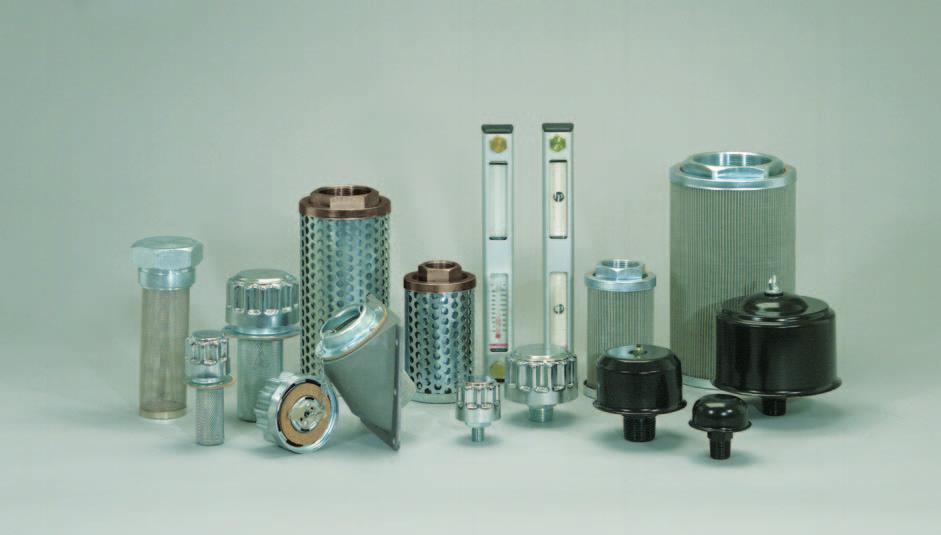
1 Hydraulic Filters Reservoir Accessories


2 Pictorial Index Hydraulic Filters RIF-10 INLINE SPIN-ON FILTERS 1.1/4 S PAGES PAGES RTI AND RFI TANK TOP FILTERS PAGES S: 1.1/4 BSPP MAX. PRESSURE: 10 bar/150 psi FILTRATION: 10 & 25 MIC ABS 10 & 25 MIC NOM FLOW RATES: to 170 LPM RIF-06 INLINE SPIN-ON FILTERS 3/4 S S: 3/4 BSPP MAX. PRESSURE: 10 bar/150 psi FILTRATION: 10 & 20 MIC ABS 10 & 25 MIC NOM FLOW RATES: to 70 LPM RIF-FA INLINE SPIN-ON FILTERS 3/8 S PAGE 363 RG & REI CLOGGING INDICATORS PAGE 370 S: 3/8 BSPT MAX. PRESSURE: 7 bar/100 psi FILTRATION: 15, 20, 32 MICRON FLOW RATES: to 18 LPM S: 1/2 to 1.1/4 BSPP MAX. PRESSURE: 10 bar/150 psi FILTRATION: 10 & 25 MICRON FLOW RATES: to 110 LPM RETURN LINE AND SUCTION LINE GAUGES AND ELECTRICAL INDICATORS RIF-12 INLINE SPIN-ON FILTERS 1.1/2 S PAGES PAGE 362 RHF HEAVY DUTY INLINE FILTERS PAGES S: 1.1/2 BSPP & SAE CODE 61 MAX. PRESSURE: 10 bar/150 psi FILTRATION: 10 & 25 MIC ABS 10 & 25 MIC NOM FLOW RATES: to 290 LPM RIF14-1 INLINE SPIN-ON FILTER 1 S RCF COMBINATION FILTERS PAGES PAGE 371 S: 1 BSPT MAX. PRESSURE: 7 bar/100 psi FILTRATION: 32 MICRON FLOW RATES: to 60 LPM S: 1/2 to 1.1/2 BSPP MAX. PRESSURE: 20 bar/290 psi FILTRATION: 10, 25 & 149 MIC FLOW RATES: to 150 LPM S: 1/2 to 1.1/2 BSPP 2.1/2 SAE CD 61 MAX. PRESSURE: 20 bar/290 psi FILTRATION: 10, 25 & 149 MIC FLOW RATES: to 540 LPM RIF15 INLINE SPIN-ON WATER TRAP FILTER S: 1 BSPT MAX. PRESSURE: 7 bar/100 psi FILTRATION: 15 MICRON FLOW RATES: to 60 LPM Page 352 QUALITY FILTERS AND ACCESSORIES


, and 10 Micron filtration (10).")

3 Pictorial Index Reservoir Accessories RLG & RLGT LEVEL AND TEMPERATURE GAUGES PAGE 372 RD DIFFUSERS PAGE 374 LENGTHS: 76 mm,127 mm & 254 mm (3, 5 & 10 ) S: 3/4 to 2 BSPP FLOW RATES: 100 to 480 LPM RFSB FILLER CAP/STRAINER/AIR BREATHERS PAGE 376 FILTERS TECHNICAL SECTION TWO SIZES. BAYONET CAP, METAL STRAINER BASKET FILTRATION: 10 & 40 MICRON DISPLACEMENT: 90 to 720 LPM RSCN SUCTION STRAINERS PAGE 373 PAGE 375 R381 PUSH-ON BREATHER/R365 FILLER STRAINER PAGE 377 S: 1/4 to 3 BSPP FILTRATION: 149 MICRON FLOW RATES: 12 to 600 LPM R60 AND R300 AIR BREATHER FILTERS S: 1/4 to 2.1/2 BSP, 3/4 UNO FILTRATION: 10, 27, 40, 149 MIC DISPLACEMENT: 90 to 4000 LPM R381: PUSH-ON BREATHER CAP R365: 2 BSP CAP, METAL STRAINER BASKET PAGE NEED FOR FILTRATION, HOW FILTERS WORK WHAT IS A MICRON?, PRESSURE DROP, BYPASS VALVES SELECTION OF FILTER SIZE, FLOW RATES FILTRATION, BETA RATINGS, ABSOLUTE FILTRATION PRESSURE DROP FLOW GRAPHS FOR FILTERS & 383 WARNINGS and FILTER SELECTION GUIDELINES & 385 EFFECT OF TEMPERATURE and VISCOSITY ON FLOW RATE and PRESSURE DROP & 387 CROSS REFERENCE FOR RYCO RIF-E and RIF-EA SPIN-ON FILTERS & 389 INSTRUCTIONS FOR CHANGING FILTER ELEMENTS IMANT NOTE ON DASH SIZES: Dash Sizes for Ports of Hydraulic Filters and Reservoir Accessories are in EIGHTHS of an inch (not SIXTEENTHS); -06 = 6/8 = 3/4 inch except that R362, R356 and R358 Series Air Breathers are sized in SIXTEENTHS of an inch. Reference is made to Filter Series in several manners in this manual. For example, an RIF-RP1210 Filter assembly is a: RYCO Inline Filter with Spin-On Canister (RIF), 1,0 bar Bypass for Return Lines (R), two parallel Canisters and BSPP Ports (P), 1.1/2 Ports (12), and 10 Micron filtration (10). It could be referred to/included in the following Filter Series groups: as an RIF Filter includes all RYCO Inline Filters with Spin-On Canisters, all types & sizes as an RIF-12 Filter includes all RYCO Inline Filters, Spin-On Canisters, 1.1/2 Ports (SAE or BSPP) as an RIF-R Filter includes all RYCO Inline Filters, Spin-On Canisters, Return Line as an RIF-RP Filter as an RIF-R12 Filter includes all RYCO Inline Filters, Return Line, two parallel Spin-On Canisters & BSPP Ports includes all RYCO Inline Filters with Spin-On canisters, Return Line, 1.1/2 SAE Code 61 or BSPP Ports Filters Accessories Adaptors Couplings Hose Intro Technical HIGHER TECHNOLOGY EQUALS GREATER PERFORMANCE Page 353
.")
 mostly have BSPP Threads. Canisters from USA ( American standard ) mostly have UNF Threads.")
4 Information about RYCO RIF-E and RIF-EA Spin-On Filters There are two series (RIF-E and RIF-EA) and two sizes (3/4 and 1.1/4 ) of Spin-On Canisters shown on pages 356 to 359. (The size 3/4 and 1.1/4 refers to the Port size of the Filter Head). These yellow Spin-On Canisters, and the Filter Heads they are used with, are sized and threaded the same as other internationally available Canisters and Heads: Canisters from Europe ( European standard ) mostly have BSPP Threads. Canisters from USA ( American standard ) mostly have UNF Threads. RYCO have Spin-On Filter Canisters and Filter Heads using both the BSPP European and the UNF American system. 3/4 SPIN-ON FILTERS PAGES For 3/4 Canisters and Heads, Post and Canister Threads are either BSPP 3/4-14 TPI or UNF 1-12 TPI. The Thread Diameters are almost the same, but the pitch of the threads is different. The Top Plates and Gaskets of the Canisters look similar. In both BSPP and UNF canisters, the Gasket is supplied fitted in a groove in the Canister. It is essential to use a BSPP Canister with a BSPP Filter Post, and a UNF Canister with a UNF Filter Post. RYCO have 3/4 Spin-On Filter Series using both the BSPP European and the UNF American system: RIF-E0610 and RIF-E0625 Spin-On Canisters have BSPP Threads RIF-EA0810 and RIF-EA0825 Spin-On Canisters have UNF Threads. BSPP European standard RIF-RH06 Filter Head 3/4-14 TPI BSPP Post Thread RIF-E0610 and RIF-E0625 Spin-On Canister 3/4-14 TPI BSPP Canister Thread Gasket is supplied fitted in Canister and seals against Gasket Seating area of Filter Head. UNF American standard A in part number denotes UNF Threads RIF-RHA06 Filter Head 1-12 TPI UNF Post Thread RIF-EA0810 and RIF-EA0825 Spin-On Canister 1-12 TPI UNF Canister Thread Gasket is supplied fitted in Canister and seals against Gasket Seating area of Filter Head. NOTE: NOTE: The last two digits of Part Number of RIF-E06 and RIF-E10 Series Canisters are the ABSOLUTE filtration rating. The last two digits of Part Number of RIF-EA08 and RIF-EA12 Series Canister are the filtration rating. See pages 378 to 381 for more information on ABSOLUTE and filtration ratings. 1. ABSOLUTE means at least 98.7% of particles of the micron size and above are removed. 2. means approximately 50% of particles of the micron size and above are removed. Part Numbers for Filter Heads on pages 354 and 355 are for Return Line Filter Heads. For Suction Line Filter Heads, replace R after dash with S, eg RIF-SH06. For Blocked Bypass Filter Heads, replace R after dash with B, eg RIF-BHA06. Page 354 QUALITY FILTERS AND ACCESSORIES
 mostly have BSPP Threads. Canisters from USA ( American standard ) mostly have UNF Threads. RYCO have 1.")


5 Information about RYCO RIF-E and RIF-EA Spin-On Filters 1.1/4 SPIN-ON FILTERS PAGES Similarly to 3/4 Spin-On Filters, for 1.1/4 Spin-On Filters: Canisters from Europe ( European standard ) mostly have BSPP Threads. Canisters from USA ( American standard ) mostly have UNF Threads. RYCO have 1.1/4 Spin-On Filter Series using both the BSPP European and the UNF American system: RIF-E1010 and RIF-E1025 Spin-On Canisters have BSPP Threads. RIF-EA1210 and RIF-EA1225 Spin-On Canisters have UNF Threads. The Top Plate of BSPP Canisters are shaped so the thread is close to the top of the Canister. The Top Plate of UNF Canisters are dished, with the thread below the top of the Canister. This difference allows the use of a Dual Post Thread on the Filter Head. BSPP 1.1/4-11 TPI Canister threads onto the top part of a Dual Post Thread. UNF 1.1/2-16 TPI Canister threads onto the bottom part of a Dual Post Thread. RYCO RIF-RH10, RIF-SH10 and RIF-BH10 1.1/4 Filter Heads, on pages 356 and 357, have dual BSPP and UNF Post Threads, to allow the use of both types of Canisters. RYCO RIF /2 Filter Heads on pages 358 and 359, using two 1.1/4 Canisters, also have Dual Post Threads. The Gasket also seals differently in the two systems, BSPP and UNF, and there are two Gasket seating areas in a Dual Post Head. The BSPP Canister Gasket is supplied fitted in a groove in the Canister. The UNF Canister Gasket is supplied loose, to be fitted into the groove in the Filter Head. BSPP European standard RIF-RH10 Filter Head 1.1/4-11 TPI BSPP post Thread RIF-E1010 and RIF-E1025 Spin-On Canister 1.1/4-11 TPI BSPP Canister Thread Gasket is supplied fitted in Canister and seals against inner Gasket Seating area of Filter Head. UNF American standard A in part number denotes UNF Threads RIF-RH10 Filter Head 1.1/2-16 TPI UNF Post Thread RIF-EA1210 and RIF-EA1225 Spin-On Canister 1.1/2-16 TPI UNF Canister Thread Gasket is supplied loose and seals against outer Gasket Seating area of Filter Head. Additionally, there are different types of Gaskets used by various manufacturers of UNF Threaded Filter Heads. Two Gaskets are supplied with RYCO RIF-EA1210 and RIF-EA1225 UNF Threaded Spin-On Canisters (only one is to be used). RIF-EA12GW wide L-Section Gasket for use with RYCO Filter Heads and other heads with similar (wide) groove. Filters Accessories Adaptors Couplings Hose Intro RIF-EA12GM square-section Gasket with green stripe for use with Filter Heads with narrow groove. Photo shows a Filter Head with single UNF Post Thread and single Gasket Seating area only. WARNING: The Gasket must be a tight fit in the groove of the Head. Use of incorrect Gasket prevents sealing, and may cause damage. Refer to pages 357, 388 and 389; and RYCO Hydraulics Technical Department for further information. Technical CONNECTING PARTNERSHIPS Page 355
, and high flow rates enable these Filters to be utilised in a wide range of applications. FEATURES OF RYCO SPIN-ON S & HEADS: Disposable Spin-On Canisters.")


6 RIF-10 Inline Spin-On Filters 1.1/4 Ports RECOMMENDED FOR: RYCO RIF-10 Series Filters are designed for installation in return lines or suction lines of both stationary and mobile hydraulic equipment. Working pressures up to 10 bar (150 psi), and high flow rates enable these Filters to be utilised in a wide range of applications. FEATURES OF RYCO SPIN-ON S & HEADS: Disposable Spin-On Canisters. Changing of filter elements is quick and simple. High efficiency. Multi layer filtration media. Available in two different Absolute filtration ratings, and two different Nominal filtration ratings. High working pressures. Specially moulded Gaskets. Rolled seam on Canisters. High collapse resistance inner core. High quality cast Aluminium Head. Tapped mounting holes. Easy to install. BSPP threaded Ports. Inlet and Outlet Ports are clearly identified. Flow direction arrow. RYCO RIF-RH10, RIF-SH10 and RIF-BH10 Filter Heads are Dual Threaded on the Filter Post giving worldwide compatibility of Spin-On Canisters. RYCO RIF-RH10, RIF-SH10 and RIF-BH10 Filter Heads can be used with both RIF-E10 and RIF-EA12 Series Spin-On Canisters. See page 385 for more information. Bypass Valve in the Aluminium Head allows the flow of oil to bypass the Canister if the Filter becomes blocked with contaminant. Two different Bypass Valve cracking pressures are available to suit Return Lines or Suction Lines, plus Blocked Bypass for special applications. Clogging Indicators available, see page 370. Tapped and Plugged Ports for Clogging Indicator. Both Positions on Inlet Port are tapped and plugged for Return Line filters. Both Positions on Outlet Port are tapped and plugged for Suction Line filters. All four Positions are tapped and plugged for Blocked Bypass filters. TECHNICAL DATA Filter Head: Cast Aluminium. Spin-On Canister Housing: Powder coated steel casing. Pressed steel top plate. Gasket: Nitrile (Buna N) oil resistant rubber. Filtration Media: Cellulose with reinforced synthetic fibres, folic impregnated resin; extensively pleated to maximise surface area available to trap contaminants, and maximise dirt holding capacity. Filtration Ratings: RIF-E1010: 10 Micron Absolute (3 Mic Nom). ß10 75, ß3 2. RIF-E1025: 25 Micron Absolute (10 Mic Nom). ß25 75, ß10 2. RIF-EA1210: 10 Micron Nominal (27 Mic Abs). ß27 75, ß10 2. RIF-EA1225: 25 Micron Nominal (36 Mic Abs). ß36 75, ß25 2. Maximum Working Pressure/Vacuum: 10 bar/150 psi in Return Line applications. 635 mmhg/25 inhg in Suction Line applications. 5,5 bar/80 psi for Return Line applications with Blocked Bypass Valve. Operating Temperature: 80 C (176 F) maximum continuous working temperature. Fluid Compatibility: Mineral/petroleum based hydraulic oils. Bypass Valve Position: In Filter Head. Bypass Valve Differential Cracking Pressure: RIF-R Series for Return Lines 1,0 bar/14.5 psi. RIF-S Series for Suction Lines 0,2 bar/2.9 psi. RIF-B Series Blocked Bypass for special applications. Clogging Indicators: RGR Gauge for return lines. Colour coded Green & Red sectors for quick visual inspection. RGS Gauge calibrated with negative pressures (for suction lines) and positive pressures (for return lines). RGS02 Gauge, Stainless Steel, calibrated with negative pressures for Suction Lines. REIR and REIS Electrical Indicators. See page 370 for more information on Clogging Indicators. Nominal Flow Rates: As shown, cause a clean element pressure drop of 0,5 bar (7.3 psi) for RIF-R and 0,03 bar (0.5 psi) for RIF-S with 30 centistoke viscosity oil (see page 380 for more detail). The actual flow rate will vary if the oil is of a different viscosity. See also page 382 for Pressure Drop Flow Graphs, pages 384 and 385 for Warnings and Filter Selection Guidelines and pages 386 and 387 for Effect of Temperature and Viscosity on Flow Rate and Pressure Drop. MOUNTING OPTIONS RYCO RIF-10 Series Filter Heads can be mounted to equipment by means of two tapped mounting holes in head. Filter Heads can be mounted directly between rigid pipes, provided that the pipes are anchored to ensure that no undue stress is placed on the Filter Head casting. Allow 35 mm (1.35 ) clearance below Spin-On Canister to allow Canister to be changed. Instructions for changing Canister are branded on the Canister, and are also shown on page 390. Page 356 QUALITY FILTERS AND ACCESSORIES
7 RIF-10 Inline Spin-On Filters 1.1/4 Ports PART NUMBERS AND SPECIFICATIONS BSPP THREADS, LAST 2 DIGITS ARE THE ABSOLUTE RATING COMPLETE FILTER BSPP FLOW MAXIMUM WORKING PRESSURE/VACUUM ABSOLUTE FILTRATION FILTRATION REPLACEMENT SPIN-ON SERIES PART NO INCH LPM MICRON MICRON PART NO PART NO Return Filter RIF-R / bar 150 psi 10 3 RIF-E1010 RIF-RH10 1,0 bar Bypass RIF-R / bar 150 psi RIF-E1025 RIF-RH10 Suction Filter RIF-S / mmhg 25 inhg 10 3 RIF-E1010 RIF-SH10 0,2 bar Bypass RIF-S / mmhg 25 inhg RIF-E1025 RIF-SH10 Blocked RIF-B / RIF-E1010 RIF-BH10 Bypass Filter RIF-B / RIF-E1025 RIF-BH10 PART NUMBERS AND SPECIFICATIONS UNF THREADS, LAST 2 DIGITS ARE THE RATING COMPLETE FILTER BSPP FLOW MAXIMUM WORKING PRESSURE/VACUUM ABSOLUTE FILTRATION FILTRATION REPLACEMENT SPIN-ON SERIES PART NO INCH LPM MICRON MICRON PART NO PART NO Return Filter RIF-RA / bar 150 psi RIF-EA1010 RIF-RH10 1,0 bar Bypass RIF-RA / bar 150 psi RIF-EA1025 RIF-RH10 Suction Filter RIF-SA / mmhg 25 inhg RIF-EA1010 RIF-SH10 0,2 bar Bypass RIF-SA / mmhg 25 inhg RIF-EA1025 RIF-SH10 Blocked RIF-BA / RIF-EA1010 RIF-BH10 Bypass Filter RIF-BA / RIF-EA1025 RIF-BH10 DIAMETER OVERALL HEIGHT HEIGHT DIMENSIONS WIDTH ACROSS S THREAD BSPP MOUNTING HOLE CENTRES MOUNTING HOLE THREADS HEAD HEAD ONLY HEAD ONLY TOTAL Filters Accessories Adaptors Couplings Hose Intro D mm H mm L mm W mm A inch X mm kg kg kg /4 48 M8 X 1,25 0,96 1,08 2,04 CROSS REFERENCE INFORMATION The Posts on RYCO RIF-RH10, RIF-SH10 and RIF-BH10 Series Heads are Dual Threaded to allow the use of both common types of Spin-On Canisters. RYCO RIF-E1010 and RIF-E1025 and European standard Canisters have Top Plate with 1.1/4-11 TPI BSPP thread to screw onto the upper part of the Dual Post Thread. RYCO RIF-EA1210 and RIF-EA1225 and American standard Canisters have a dished Top Plate with 1.1/2-16 TPI UNF thread to screw onto the lower part of the Dual Post Thread. HIGHER TECHNOLOGY EQUALS GREATER PERFORMANCE RYCO RIF-E1010 and RIF-E1025 Canisters, threaded 1.1/4-11 TPI BSPP, can be used on standard BSPP or Dual Threaded Post Filter Heads. RYCO RIF-EA1210 and RIF-EA1225 Canisters, threaded 1.1/2-16 TPI UNF, can be used on standard UNF or Dual Threaded Post Filter Heads. For Cross Reference information, please see pages 354 and 355, and pages 388 and 389. Page 357 Technical

. Disposable Spin-On Canisters. Changing of filter elements is quick and simple. High efficiency.")
8 RIF-12 Inline Spin-On Filters 1.1/2 Ports RIF-V12 RIF-V12 RIF-P12 RIF-C12 RECOMMENDED FOR: RYCO RIF-12 Series Filters are designed for installation in return lines or suction lines of both stationary and mobile hydraulic equipment. Working pressures up to 10 bar (150 psi), and high flow rates enable these Filters to be utilised in a wide range of applications. FEATURES OF RYCO SPIN-ON S & HEADS: RIF-V12 series with BSPP Ports. RIF-P12 series with BSPP Ports. RIF-C12 series with SAE Code 61 Ports (with UNC Bolt Holes). Disposable Spin-On Canisters. Changing of filter elements is quick and simple. High efficiency. Multi layer filtration media. Available in two different Absolute filtration ratings, and two different Nominal filtration ratings. High working pressures. Specially moulded Gaskets. Rolled seam on Canisters. High collapse resistance inner core. High quality cast Aluminium Head. Tapped mounting holes. Easy to install. RYCO RIF-12 Filter Heads are Dual Threaded on the Filter Post giving world wide compatibility of Spin-On Canisters. RIF-12 Filter Heads can be used with both RIF-E10 and RIF-EA12 Series Spin-On Canisters. See page 355 for more information. For Cross Reference information, see information on bottom of page 357; the same Spin-On Canisters are used. See also pages 354 and 355, and 388 and 389. Bypass Valve in the Aluminium Head allows the flow of oil to bypass the Canister if the Filter becomes blocked with contaminant. Two different Bypass Valve cracking pressures are available to suit Return Line or Suction Lines, plus Blocked Bypass for special applications. Clogging Indicators available, see page 370. Tapped and Plugged Ports for Clogging Indicator. For RIF-V12 Series, there are two Positions, one each for Return Line and Suction Line applications. Both are tapped and plugged. For RIF-P12 and RIF-C12 Series, both Return Line Positions on Inlet side for Return Line filters are tapped and plugged. Both Suction Line Positions on Outlet side for Suction Line filters are tapped and plugged. TECHNICAL DATA Filter Head: Cast Aluminium. Spin-On Canister Housing: Powder coated steel casing. Pressed steel top plate. Gasket: Nitrile (Buna N) oil resistant rubber. Filtration Media: Cellulose with reinforced synthetic fibres, folic impregnated resin; extensively pleated to maximise surface area available to trap contaminants and maximise dirt holding capacity. Filtration Ratings: RIF-E1010: 10 Micron Absolute (3 Mic Nom). ß10 75, ß3 2. RIF-E1025: 25 Micron Absolute (10 Mic Nom). ß25 75, ß10 2. RIF-EA1210: 10 Micron Nominal (27 Mic Abs). ß27 75, ß10 2. RIF-EA1225: 25 Micron Nominal (36 Mic Abs). ß36 75, ß25 2. Maximum Working Pressure/Vacuum: 10 bar/150 psi in Return Line applications. 635 mmhg/25 inhg in Suction Line applications. 5,5 bar/80 psi for Return Line applications with Blocked Bypass Valve. Operating Temperature: 80 C (176 F) maximum continuous working temperature. Fluid Compatibility: Mineral/petroleum based hydraulic oils. Bypass Valve Position: In Filter Head. Bypass Valve Differential Cracking Pressure: RIF-R Series for return lines 1,0 bar/14.5 psi. RIF-S Series for suction lines 0,2 bar/2.9 psi. RIF-B Series Blocked Bypass for special applications. Clogging Indicators: RGR Gauge for Return Lines. Colour coded Green & Red sectors for quick visual inspection. RGS Gauge calibrated with negative pressures (for Suction Lines) and positive pressures (for Return Lines). RGS02 Gauge, Stainless Steel, calibrated with negative pressures for Suction Lines. REIR and REIS Electrical Indicators. See page 370 for more information on Clogging Indicators. Nominal Flow Rates: As shown, cause a clean element pressure drop of 0,5 bar (7.3 psi) for RIF-R and 0,03 bar (0.5 psi) for RIF-S with 30 centistoke viscosity oil (see page 380 for more detail). The actual flow rate will vary if the oil is of a different viscosity. See also page 382 for Pressure Drop Flow Graphs, pages 384 and 385 for Warnings and Filter Selection Guidelines, and pages 386 and 387 for Effect of Temperature and Viscosity on Flow Rate and Pressure Drop. MOUNTING OPTIONS RYCO RIF-12 Series Filter Heads can be mounted to equipment by means of two or four tapped mounting holes in head. Filter Heads can be mounted directly between rigid pipes, provided that the pipes are anchored to ensure that no undue stress is placed on the Filter Head casting. Allow 35 mm (1.35 ) clearance below Spin-On Canister to allow Canister to be changed. Instructions for changing Canister are branded on the Canister, and are also shown on page 390. Page 358 QUALITY FILTERS AND ACCESSORIES
9 RIF-12 Inline Spin-On Filters 1.1/2 Ports PART NUMBERS AND SPECIFICATIONS BSPP THREADS, LAST 2 DIGITS ARE THE ABSOLUTE RATING COMPLETE FILTER PART NUMBERS AND SPECIFICATIONS UNF THREADS, LAST 2 DIGITS ARE THE RATING COMPLETE FILTER BSPP FLOW MAXIMUM WORKING PRESSURE/VACUUM ABSOLUTE FILTRATION FILTRATION REPLACEMENT SPIN-ON SERIES PART NO INCH LPM MICRON MICRON PART NO PART NO RIF-RVA /2 BSPP bar 150 psi RIF-EA1210 RIF-RVH12 RIF-RVA /2 BSPP bar 150 psi RIF-EA1225 RIF-RVH12 Return Filter RIF-RPA /2 BSPP bar 150 psi RIF-EA1210 RIF-RPH12 1,0 bar Bypass RIF-RPA /2 BSPP bar 150 psi RIF-EA1225 RIF-RPH12 RIF-RCA /2 CD bar 150 psi RIF-EA1210 RIF-RCH12 RIF-RCA /2 CD bar 150 psi RIF-EA1225 RIF-RCH12 Suction Filter 0,2 bar Bypass Blocked Bypass Filter DIMENSIONS RIF P12/C12 SERIES BSPP FLOW MAXIMUM WORKING PRESSURE/VACUUM ABSOLUTE FILTRATION FILTRATION REPLACEMENT SPIN-ON SERIES PART NO INCH LPM MICRON MICRON PART NO PART NO RIF-RV /2 BSPP bar 150 psi 10 3 RIF-E1010 RIF-RVH12 RIF-RV /2 BSPP bar 150 psi RIF-E1025 RIF-RVH12 Return Filter RIF-RP /2 BSPP bar 150 psi 10 3 RIF-E1010 RIF-RPH12 1,0 bar Bypass RIF-RP /2 BSPP bar 150 psi RIF-E1025 RIF-RPH12 RIF-RC /2 CD bar 150 psi 10 3 RIF-E1010 RIF-RCH12 RIF-RC /2 CD bar 150 psi RIF-E1025 RIF-RCH12 Suction Filter 0,2 bar Bypass Blocked Bypass Filter HEAD ONLY RIF-SV /2 BSPP mmhg 25 inhg 10 3 RIF-E1010 RIF-SVH12 RIF-SV /2 BSPP mmhg 25 inhg RIF-E1025 RIF-SVH12 RIF-SP /2 BSPP mmhg 25 inhg 10 3 RIF-E1010 RIF-SPH12 RIF-SP /2 BSPP mmhg 25 inhg RIF-E1025 RIF-SPH12 RIF-SC /2 CD mmhg 25 inhg 10 3 RIF-E1010 RIF-SCH12 RIF-SC /2 CD mmhg 25 inhg RIF-E1025 RIF-SCH12 RIF-BV /2 BSPP 10 3 RIF-E1010 RIF-BVH12 RIF-BV /2 BSPP RIF-E1025 RIF-BVH12 RIF-BP /2 BSPP 10 3 RIF-E1010 RIF-BPH12 RIF-BP /2 BSPP RIF-E1025 RIF-BPH12 RIF-BC /2 CD RIF-E1010 RIF-BCH12 RIF-BC /2 CD RIF-E1025 RIF-BCH12 HEAD ONLY RIF-SVA /2 BSPP mmhg 25 inhg RIF-EA1210 RIF-SVH12 RIF-SVA /2 BSPP mmhg 25 inhg RIF-EA1225 RIF-SVH12 RIF-SPA /2 BSPP mmhg 25 inhg RIF-EA1210 RIF-SPH12 RIF-SPA /2 BSPP mmhg 25 inhg RIF-EA1225 RIF-SPH12 RIF-SCA /2 CD mmhg 25 inhg RIF-EA1210 RIF-SCH12 RIF-SCA /2 CD mmhg 25 inhg RIF-EA1225 RIF-SCH12 RIF-BVA /2 BSPP RIF-EA1210 RIF-BVH12 RIF-BVA /2 BSPP RIF-EA1225 RIF-BVH12 RIF-BPA /2 BSPP RIF-EA1210 RIF-BPH12 RIF-BPA /2 BSPP RIF-EA1225 RIF-BPH12 RIF-BCA /2 CD RIF-EA1210 RIF-BCH12 RIF-BCA /2 CD RIF-EA1225 RIF-BCH12 Filters Accessories Adaptors Couplings Hose Intro RIF V12 SERIES RYCO FILTER HEAD TOTAL Technical SERIES kg kg kg RIF-V12 1,00 1,08 3,16 RIF-P12 & RIF-C12 2,60 1,08 4,76 CONNECTING PARTNERSHIPS Page 359
, and high flow rates enable these Filters to be utilised in a wide range of applications. FEATURES OF RYCO SPIN-ON S & HEADS: Disposable Spin-On Canisters.")

10 RIF-06 Inline Spin-On Filters 3/4 Ports RECOMMENDED FOR: RYCO RIF-06 Series Filters are designed for installation in return lines or suction lines of both stationary and mobile hydraulic equipment. Working pressures up to 10 bar (150 psi), and high flow rates enable these Filters to be utilised in a wide range of applications. FEATURES OF RYCO SPIN-ON S & HEADS: Disposable Spin-On Canisters. Changing of filter elements is quick and simple. High efficiency. Multi layer filtration media. Available in two different Absolute filtration ratings, and two different Nominal filtration ratings. High working pressures. Rolled seam on Canisters. High collapse resistance inner core. High quality cast Aluminium Head. RYCO RIF-RH06, RIF-SH06 and RIF-BH06 Filter Heads have BSPP threaded post and are used with RIF-E0610 and RIF-E0625 Spin-On Canisters. RYCO RIF-RHA06, RIF-SHA06 and RIF-BHA06 Filter Heads have UNF threaded post and are used with RIF-EA0810 and RIF-EA0825 Spin-On Canisters. See page 354 for more information. Tapped mounting holes. Easy to install. BSPP threaded Ports. Inlet and Outlet Ports are clearly identified. Flow direction arrow. Bypass Valve in the Aluminium Head allows the flow of oil to bypass the Canister if the Filter becomes blocked with contaminant. Two different Bypass Valve cracking pressures are available to suit return or suction lines, plus Blocked Bypass for special applications. Clogging Indicators available, see page 370. Tapped and Plugged Ports for Clogging Indicator. Both Positions on Inlet Port are tapped and plugged for Return Line filters. Both Positions on Outlet Port are tapped and plugged for Suction Line filters. All four Positions are tapped and plugged for Blocked Bypass filters. TECHNICAL DATA Filter Head: Cast Aluminium. Spin-On Canister Housing: Powder coated steel casing. Pressed steel top plate. Gasket: Nitrile (Buna N) oil resistant rubber; rectangular section. Filtration Media: Cellulose with reinforced synthetic fibres, folic impregnated resin; extensively pleated to maximise surface area available to trap contaminants and maximise dirt holding capacity. Filtration Ratings: RIF-E0610: 10 Micron Absolute (3 Mic Nom). ß10 75, ß3 2. RIF-E0625: 25 Micron Absolute (10 Mic Nom). ß20 75, ß10 2. RIF-EA0810: 10 Micron Nominal (25 Mic Abs). ß25 75, ß10 2. RIF-EA0825: 25 Micron Nominal (32 Mic Abs). ß32 75, ß25 2. Maximum Working Pressure/Vacuum: 10 bar/150 psi in Return Line applications. 635 mmhg/25 inhg in Suction Line applications. 5,5 bar/80 psi for Return Line applications with Blocked Bypass Valve. Operating Temperature: 80 C (176 F) maximum continuous working temperature. Fluid Compatibility: Mineral/petroleum based hydraulic oils. Bypass Valve Position: In Filter Head. Bypass Valve Differential Cracking Pressure: RIF-R Series for Return Lines 1,0 bar/14.5 psi. RIF-S Series for Suction Lines 0,2 bar/2.9 psi. RIF-B Series Blocked Bypass for special applications. Clogging Indicators: RGR Gauge for return lines. Colour coded Green & Red sectors for quick visual inspection. RGS Gauge calibrated with negative pressures (for suction lines) and positive pressures (for return lines). RGS02 Gauge, Stainless Steel, calibrated with negative pressures for Suction Lines. REIR and REIS Electrical Indicators. See page 370 for more information on Clogging Indicators. Nominal Flow Rates: As shown, cause a clean element pressure drop of 0,5 bar (7.3 psi) for RIF-R and 0,03 bar (0.5 psi) for RIF-S with 30 centistoke viscosity oil (see page 380 for more detail). The actual flow rate will vary if the oil is of a different viscosity. See also page 382 for Pressure Drop Flow Graphs, pages 384 and 385 for Warnings and Filter Selection Guidelines, and pages 386 and 387 for Effect of Temperature and Viscosity on Flow Rate and Pressure Drop. MOUNTING OPTIONS RYCO RIF-06 Series Filter Heads can be mounted to equipment by means of two tapped mounting holes in head. Filter Heads can be mounted directly between rigid pipes, provided that the pipes are anchored to ensure that no undue stress is placed on the Filter Head casting. Allow 25 mm (1 ) clearance below Spin-On Canister to allow Canister to be changed. Instructions for changing Canister are branded on the Canister, and are also shown on page 390. Page 360 QUALITY FILTERS AND ACCESSORIES
11 RIF-06 Inline Spin-On Filters 3/4 Ports PART NUMBERS AND SPECIFICATIONS BSPP THREADS, LAST 2 DIGITS ARE THE ABSOLUTE RATING COMPLETE FILTER DIMENSIONS BSPP FLOW MAXIMUM WORKING PRESSURE/VACUUM ABSOLUTE FILTRATION FILTRATION REPLACEMENT SPIN-ON SERIES PART NO INCH LPM MICRON MICRON PART NO PART NO Return Filter RIF-R0610 3/ bar 150 psi 10 3 RIF-E0610 RIF-RH06 1,0 bar Bypass RIF-R0625 3/ bar 150 psi RIF-E0625 RIF-RH06 Suction Filter RIF-S0610 3/ mmhg 25 inhg 10 3 RIF-E0610 RIF-SH06 0,2 bar Bypass RIF-S0625 3/ mmhg 25 inhg RIF-E0625 RIF-SH06 Blocked RIF-B0610 3/ RIF-E0610 RIF-BH06 Bypass Filter RIF-B0625 3/ RIF-E0625 RIF-BH06 PART NUMBERS AND SPECIFICATIONS UNF THREADS, LAST 2 DIGITS ARE THE RATING COMPLETE FILTER BSPP FLOW MAXIMUM WORKING PRESSURE/VACUUM ABSOLUTE FILTRATION FILTRATION REPLACEMENT SPIN-ON SERIES PART NO INCH LPM MICRON MICRON PART NO PART NO Return Filter RIF-RA0610 3/ bar 150 psi RIF-EA0810 RIF-RHA06 1,0 bar Bypass RIF-RA0625 3/ bar 150 psi RIF-EA0825 RIF-RHA06 Suction Filter RIF-SA0610 3/ mmhg 25 inhg RIF-EA0810 RIF-SHA06 0,2 bar Bypass RIF-SA0625 3/ mmhg 25 inhg RIF-EA8625 RIF-SHA06 Blocked RIF-BA0610 3/ RIF-EA0810 RIF-BHA06 Bypass Filter RIF-BA0625 3/ RIF-EA0825 RIF-BHA06 DIAMETER OVERALL HEIGHT HEIGHT WIDTH ACROSS S THREAD BSPP MOUNTING HOLE CENTRES MOUNTING HOLE THREADS HEAD HEAD ONLY HEAD ONLY TOTAL Filters Accessories Adaptors Couplings Hose Intro D mm H mm L mm W mm A inch X mm kg kg kg /4 38 M6 x 1 0,36 0,48 0,84 CROSS REFERENCE INFORMATION The Posts on RYCO RIF-RH06, RIF-SH06 and RIF-BH06 Filter Heads have 3/4-14 TPI BSPP thread. RYCO RIF-E0610 and RIF-E0625 and European standard Canisters have 3/4-14 TPI BSPP thread. The Posts on RYCO RIF-RHA06, RIF-SHA06 and RIF-BHA06 Filter Heads have 1-12 TPI UNF thread. RYCO RIF-EA0810 and RIF-EA0825 and American standard Canisters have 1-12 TPI UNF thread. RYCO RIF-E0610 and RIF-E0625 Canisters can be used on standard BSPP threaded post Filter Heads. RYCO RIF-EA0810 and RIF-EA0825 Canisters can be used on standard UNF threaded post Filter Heads. For Cross Reference information, please see page 354, and pages 388 and 389. Technical HIGHER TECHNOLOGY EQUALS GREATER PERFORMANCE Page 361
12 RIF14-1 Inline Spin-On Filters 1 Ports RECOMMENDED FOR: RYCO RIF14-1 Filters are designed for installation in mineral and petroleum based hydraulic oil return lines, to maximum working temperature 80 C (176 F) and maximum working pressure 7 bar/100 psi. FEATURES: Disposable Spin-On Canisters. Changing of filter element is quick and simple. Cast Aluminium Head with tapped mounting holes. Easy to install. 1 inch BSPT threaded Ports. Inlet and Outlet Ports are clearly identified by flow direction arrow. Bypass Valve in the Aluminium Head allows the flow of oil to bypass the Canister if the Filter becomes blocked with contaminant. TECHNICAL DATA Filter Head: Cast Aluminium. Spin-On Canister Housing: Painted steel casing. Pressed steel top plate. Gasket: Nitrile (Buna N) oil resistant rubber. TECHNICAL DATA (CONTINUED) Filtration Media: Cellulose with synthetic fibres added, phenolic resin impregnated, and silicone treated for water resistance; extensively pleated to maximise surface area available to trap contaminants, and maximise dirt holding capacity. Filtration Rating: 32 Micron Nominal. Maximum Working Pressure: 7 bar (100 psi). Not suitable for Suction Line applications. Operating Temperature: 80 C (176 F) maximum continuous working temperature. Fluid Compatibility: Mineral/petroleum based hydraulic oils. Bypass Valve Position: In Filter Head. Bypass Valve Differential Cracking Pressure: 0,7 bar (10 psi) Nominal Flow Rates: As shown, cause a clean element pressure drop of 0,3 bar (4.4 psi) with 30 centistoke viscosity oil (see page 380 for more detail). The actual flow rate will vary if the oil is of a different viscosity. See also page 383 for Pressure Drop Flow Graphs, pages 384 and 385 for Warnings and Filter Selection Guidelines, and pages 386 and 387 for Effect of Temperature and Viscosity on Flow Rate and Pressure Drop. PART NUMBERS AND SPECIFICATIONS COMPLETE FILTER BSPP FLOW MAXIMUM WORKING PRESSURE FILTRATION REPLACEMENT SPIN-ON PART NO INCH LPM bar psi MICRON PART NO RIF R14 DIMENSIONS DIAMETER OVERALL HEIGHT HEIGHT WIDTH ACROSS S THREAD BSPT MOUNTING HOLE CENTRES MOUNTING HOLE THREADS HEAD TOTAL D mm H mm L mm W mm A inch X mm kg kg kg ,3 3/8-16 0,49 0,48 0,97 MOUNTING OPTIONS RYCO RIF14-1 Series Filter Heads can be mounted to equipment by means of two tapped mounting holes in head. Filter Heads can be mounted directly between rigid pipes provided, that the pipes are anchored to ensure that no undue stress is placed on the Filter Head casting. Allow 15 mm (0.6 ) clearance below Spin-On Canister to allow Canister to be changed. Instructions for changing Canister are shown on page 390. Page 362 QUALITY FILTERS AND ACCESSORIES

13 RIF-FA Inline Spin-On Filters 3/8 Ports RECOMMENDED FOR: RYCO RIF-FA9 and RIF-FA10 Filters are designed for installation in mineral and petroleum based hydraulic oil return lines. RYCO RIF-FA8 and RIF-FA39 Filters are designed for petrol and diesel fuel filtration. Not suitable for aviation applications. FEATURES: Disposable Spin-On Canisters. Changing of filter elements is quick and simple. Cast Aluminium Head with tapped mounting holes. Easy to install. 3/8 BSPT threaded Ports. Inlet and Outlet Ports are clearly identified by a flow direction arrow. Filter Head dimensions are the same for all RIF-FA Series. Bypass Valve built into the Canister of RIF-FA9 and RIF-FA10 allows the flow of oil to bypass the Canister if the Filter becomes blocked with contaminant. RIF-FA8 and RIF-FA39 have no Bypass Valve. Spin-On Canisters must be replaced at regular intervals, before clogging occurs. Allow 20 mm (3/4 ) clearance below Spin-On Canister to allow Canister to be changed. Instructions for changing Canister are shown on page 390. PART NUMBERS AND SPECIFICATIONS COMPLETE FILTER BSPP FLOW TECHNICAL DATA Filter Head: Cast Aluminium. Spin-On Canister Housing: Painted steel casing. Z39 Canister is also zinc passivated inside and out for extra corrosion resistance. Pressed steel top plate. Gasket: Nitrile (Buna N) oil resistant rubber. Filtration Media: Cellulose, phenolic resin impregnated and silicone treated for water resistance, extensively pleated to maximise surface area available to trap contaminants, and maximise dirt holding capacity. Maximum Working Pressure: See table below. Not suitable for Suction Line applications. Operating Temperature: 80 C (176 F) maximum continuous working temperature. Bypass Valve Differential Cracking Pressure & Location: RIF-FA9 and RIF-FA10: 1,0 bar (14.5 psi) in Canister. RIF-FA8 and RIF-FA39: no Bypass Valve. Nominal Flow Rates: As shown below cause a clean element pressure drop as follows: with 30 centistoke viscosity oil; 0,5 bar (7.3 psi) for RIF-FA9 and RIF-FA10 (see page 380 for more detail). The actual flow rate will vary if the oil is of a different viscosity. with petrol and diesel fuel; 0,3 bar (4.4 psi) for RIF-FA8 and RIF-FA39. See also page 383, pages 384 and 385, and pages 386 and 387 for more information. MAXIMUM WORKING PRESSURE FILTRATION REPLACEMENT SPIN-ON PART NO INCH LPM bar psi MICRON PART NO RIF-FA10 3/ Z89A RIF-FA9 3/ Z9 RIF-FA8 3/8 18 5, Z8 RIF-FA39 3/8 18 5, Z39 Filters Accessories Adaptors Couplings Hose Intro DIMENSIONS COMPLETE FILTER DIAMETER OVERALL HEIGHT HEIGHT WIDTH ACROSS S THREAD BSPT MOUNTING HOLE CENTRES MOUNTING HOLE THREADS HEAD TOTAL PART NO D mm H mm L mm W mm A inch X mm BSW kg kg kg RIF-FA /8 38,1 5/ ,33 0,41 0,74 RIF-FA /8 38,1 5/ ,33 0,46 0,79 RIF-FA /8 38,1 5/ ,33 0,48 0,81 RIF-FA /8 38,1 5/ ,33 0,39 0,72 Technical CONNECTING PARTNERSHIPS Page 363
 and high flow rates enable these Filters to be used in a wide range of applications.")

14 RHF Heavy Duty Inline Filters RECOMMENDED FOR HEAVY DUTY: RYCO RHF Series Heavy Duty Inline Filters are designed for installation in return lines or suction lines of both stationary and mobile hydraulic equipment. Heavy duty design, maximum working pressures up to 20 bar (290 psi) and high flow rates enable these Filters to be used in a wide range of applications. They may also be used for low pressure delivery applications. There are three sizes: RHF-05, RHF-10 and RHF-20; with RHF-10 and RHF-20 models each available with two different Port sizes. In addition to standard Filter Elements, 149 Micron Stainless Steel Mesh Filter Elements are available. They are especially suitable for Suction Line use, as they are easier to service than an in-tank Suction Strainer. FEATURES: All Aluminium Cast Construction. One Piece castings for Filter Head and Bowl. Tapped mounting holes. Easy to install. BSPP threaded Ports. Inlet and Outlet Ports are clearly identified. Sealing of Filter Head and Bowl is by O Ring located in groove in Bowl. Bypass Valve in the Aluminium Head. Two different Bypass Valve cracking pressures are available to suit Return Lines or Suction Lines, plus Blocked Bypass for special applications. Drain Plug on RHF-10 and RHF-20 sizes allows Filter to be drained prior to changing Filter Element. Clogging Indicators available, see page 370. Tapped and Plugged Port for Clogging Indicator. Position 3 on Inlet Port is tapped (for Return Line Filters). If required, Positions 1, 4 or 6 can also be tapped. TECHNICAL DATA Filter Head and Bowl: Cast Aluminium. Gasket: Nitrile (Buna N) oil resistant rubber O Ring between Filter Head and Bowl. Filtration Ratings: 10 Micron Nominal; 25 Micron Nominal; and 149 Micron Absolute. Filtration Media: 10 and 25 Micron Nominal are Cellulose, phenolic resin impregnated; 149 Micron is Stainless Steel Mesh. All are extensively pleated to maximise surface area available to trap contaminants, and maximise dirt holding capacity. Maximum Working Pressure/Vacuum: 20 bar/290 psi in Return Line applications. 635 mmhg/25 inhg Maximum Vacuum in Suction Line applications. Recommended use for suction lines is Stainless Steel Mesh Filter Element, Cellulose not recommended. 5.5 bar/80 psi for Return Line applications with Blocked Bypass Valve. Operating Temperature: 80 C (176 F) maximum continuous working temperature. Fluid Compatibility: Mineral/petroleum based hydraulic oils. Bypass Valve Position: In Filter Head. Bypass Valve Differential Cracking Pressure: RIF-R Series for return lines 1,0 bar/14.5 psi. RIF-S Series for suction lines 0,2 bar/2.9 psi. RIF-B Series Blocked Bypass for special applications. Clogging Indicators: RGR Gauge for Return Lines. Colour coded Green & Red sectors for quick visual inspection. RGS Gauge calibrated with negative pressures (for Suction Lines) and positive pressures (for Return Lines). RGS02 Gauge, Stainless Steel, calibrated with negative pressures for Suction Lines. REIR and REIS Electrical Indicators. See page 370 for more information on Clogging Indicators. Nominal Flow Rates: As shown, cause a clean element pressure drop of 0,5 bar (7.3 psi) or RHF-R and 0,03 bar (0.5 psi) for RHF-S with 30 centistoke viscosity oil (see page 380 for more detail). The actual flow rate will vary if the oil is of a different viscosity. See also page 383 for Pressure Drop Flow Graphs, pages 384 and 385 for Warnings and Filter Selection Guidelines, and pages 386 and 387 for Effect of Temperature and Viscosity on Flow Rate and Pressure Drop. MOUNTING OPTIONS RYCO RHF Series Filters can be mounted to equipment by means of two tapped mounting holes in head. Filters can be mounted directly between rigid pipes, provided that the pipes are anchored to ensure that no undue stress is placed on the Head casting. Allow length L of Bowl clearance below Bowl to allow Filter Elements to be changed. Instructions for changing filter elements are shown on page 390. Page 364 QUALITY FILTERS AND ACCESSORIES
15 RHF Heavy Duty Inline Filters PART NUMBERS AND SPECIFICATIONS DIMENSIONS COMPLETE FILTER BSPP FLOW MAXIMUM WORKING PRESSURE/VACUUM FILTRATION REPLACEMENT FILTER ELEMENT SERIES PART NO INCH LPM MICRON PART NO RHF-R / bar 290 psi 10 RHF-E0510 RHF-R / bar 290 psi 25 RHF-E0525 RHF-R / bar 290 psi 10 RHF-E1010 RHF-R / bar 290 psi 25 RHF-E1025 Return Filter RHF-R bar 290 psi 10 RHF-E1010 1,0 bar Bypass RHF-R bar 290 psi 25 RHF-E1025 RHF-R / bar 290 psi 10 RHF-E2010 RHF-R / bar 290 psi 25 RHF-E2025 RHF-R / bar 290 psi 10 RHF-E2010 RHF-R / bar 290 psi 25 RHF-E2025 Suction Filter 0,2 bar Bypass Blocked Bypass Filter RHF-S / mmhg 25 inhg 149 RHF-E05149 RHF-S / mmhg 25 inhg 149 RHF-E10149 RHF-S mmhg 25 inhg 149 RHF-E10149 RHF-S / mmhg 25 inhg 149 RHF-E20149 RHF-S / mmhg 25 inhg 149 RHF-E20149 RHF-B0504XX 1/2 XX RHF-E05XX RHF-B1006XX 3/4 REPLACE XX IN PART NUMBER XX RHF-E10XX RHF-B1008XX 1 WITH 10, 25 OR 149 MICRON XX RHF-E10XX RHF-B2010XX 1.1/4 AS REQUIRED. XX RHF-E20XX RHF-B2012XX 1.1/2 XX RHF-E20XX Filters Accessories Adaptors Couplings Hose Intro CASTING SIZE BOWL DIAMETER OVERALL HEIGHT BOWL HEIGHT WIDTH ACROSS S THREAD BSPP CENTRE TO TOP HEAD TOP TO GASKET MOUNTING HOLE CENTRES MOUNTING HOLE THREADS FILTER ELEMENT D mm H mm L mm W mm A inch C mm Z mm X mm kg kg RHF / M8 x 1,25 0,12 0,9 RHF /4 or M8 x 1,25 0,15 1,5 RHF /4 or 1.1/ M10 x 1,5 0,37 3,5 TOTAL Technical HIGHER TECHNOLOGY EQUALS GREATER PERFORMANCE Page 365


16 RTI and RFI Tank Top Filters RTI SERIES RFI SERIES RECOMMENDED FOR: RYCO RTI and RFI Series Tank Top Filters are designed for Return Line installation on the top of hydraulic oil reservoirs on earth moving, construction, agricultural and industrial equipment. They are compact and easy to mount, and only a small part of the Filter projects above the top of the reservoir. The Filter Element is replaceable by removing the Top Cover Plate. RTI Tank Immersed Series has Inlet Port above the top of the tank. RFI Fully Immersed Series has Inlet Port below the top of the tank. FEATURES: All Aluminium Cast Construction. One-Piece casting for Main Body Housing. Cast Top Cover Plate. Maximum Working Pressure 10 bar (150 psi) all sizes. Inlet Port (BSPP) is at side of Filter. NOTE: RTI-R10 has two Inlet ports. Both can be used, otherwise one must be plugged - plug not supplied. Outlet Port (BSPP) is at bottom of Filter. Easy installation of RYCO RD Series Diffuser onto Outlet Port, see page 374. Outlet Port can be extended below the level of the oil, to reduce foaming and aeration. O Ring seals Top Cover Plate to Main Body Housing. Bypass Valve built into the Filter Element. Flow of oil bypasses the Filter Element if the Filter becomes blocked with contaminant. Permanent magnet bonded to bottom of Top Cover Plate to catch coarse ferrous particles. Gauge Port tapped into Top Cover Plate. Clogging Indicators available, see page 370. Supplied with Gasket to seal Filter to Tank. RTI Series have O Ring located in groove in mounting flange, to seal filter housing to reservoir. RFI Series have Cork Gasket, to seal filter housing to reservoir. TECHNICAL DATA Main Body Housing and Top Cover Plate: Cast Aluminium. Gaskets: 1. Nitrile (Buna N) oil resistant rubber O Ring between Main Body Housing and Top Cover Plate. 2. RTI Series: O Ring supplied for seal between Main Body Housing and Tank. RFI Series: Cork Gasket supplied for seal between Main Body Housing and Tank. Filtration Media: Cellulose, phenolic resin impregnated; extensively pleated to maximise surface area available to trap contaminants, and maximise dirt holding capacity. Filtration Ratings: 10 Micron Nominal, and 25 Micron Nominal. Maximum Working Pressure: 10 bar/150 psi in Return Line applications. Not suitable for Suction Line applications. Operating Temperature: 80 C (176 F) maximum continuous working temperature. Fluid Compatibility: Mineral/petroleum based hydraulic oils. Bypass Valve Position: In Filter Cartridge. Bypass Valve Differential Cracking Pressure: 1,0 bar/14.5 psi. Clogging Indicators: RGR Gauge for Return lines. Colour coded Green & Red sectors for quick visual inspection. REIR Electrical Indicators. See page 370 for more information on Clogging Indicators. Nominal Flow Rates: As shown, cause a clean element pressure drop of 0,5 bar (7.3 psi) with 30 centistoke viscosity oil (see page 380 for more detail). The actual flow rate will vary if the oil is of a different viscosity. See also page 383 for Pressure Drop Flow Graphs, pages 384 and 385 for Warnings and Filter Selection Guidelines, and pages 385 and 386 for Effect of Temperature and Viscosity on Flow Rate and Pressure Drop. MOUNTING OPTIONS RYCO RTI and RFI Series Filters are mounted in the top of the reservoir. A circular hole is cut in the reservoir. Mounting bolt holes are drilled (and tapped if required) and the Filter Housing is bolted in place. The Filters can be mounted inline between rigid pipes, provided that the pipes are anchored to ensure that no undue stress is placed on the Housing casting, and the housing is supported. Instructions for changing Filter Element are shown on page 390. RTI RFI Page 366 QUALITY FILTERS AND ACCESSORIES
17 RTI and RFI Tank Top Filters PART NUMBER AND SPECIFICATIONS COMPLETE FILTER * NOTE: RTI-R10 has two Inlet Ports. Both can be used, otherwise one must be plugged - plug not supplied. NOTE: RTI-E and RFI-E Filter Elements are interchangeable (except RTI-E1010, RTI-E1025, RFI-E1010 and RFI-E1025). NOTE: RTI-R08 has 1 inch BSPP Inlet Port and 3/4 inch BSPP Outlet Port. DIMENSIONS RTI SERIES BSPP FLOW MAXIMUM WORKING PRESSURE RFI SERIES FILTRATION REPLACEMENT FILTER ELEMENT PART NO INCH LPM BAR psi MICRON PART NO RTI-R0410 1/ RTI-E0410 RTI-R0425 1/ RTI-E0425 RTI-R0610 3/ RTI-E0610 RTI-R0625 3/ RTI-E0625 RTI-R INLET 3/4 OUTLET RTI-E0810 RTI-R INLET 3/4 OUTLET RTI-E0825 RTI-R1010* 1.1/4* RTI-E1010 RTI-R1025* 1.1/4* RTI-E1025 RFI-R0410 1/ RFI-E0410 RFI-R0425 1/ RFI-E0425 RFI-R0610 3/ RFI-E0610 RFI-R0625 3/ RFI-E0625 RFI-R RFI-E0810 RFI-R RFI-E0825 RFI-R / RFI-E1010 RFI-R / RFI-E1025 RYCO FILTER SERIES THREAD BSPP BOWL DIAMETER INTO TANK HEIGHT HEIGHT WIDTH TO CENTRE CENTRE TO TOP HEAD TOP TO GASKET MOUNTING DIMENSIONS HOLE CIRCLE APERTURE DIAMETER HOLE DIAMETER MOUNTING HOLES RTI & RFI FILTER ELEMENT A inch E mm L mm D mm W mm C mm Z mm B mm X mm N mm kg kg RTI-R04 1/ ,6 x 2 0,10 0,72 RTI-R06 3/ ,2 x 2 0,16 1,42 RTI-R08 1 IN 3/4 OUT ,2 x 2 0,22 1,70 RTI-R10 1.1/ ,5 x 4 0,57 4,20 TOTAL RFI-R04 1/ ,0 x 2 0,10 0,73 RFI-R06 3/ ,0 x 2 0,16 1,10 RFI-R ,0 x 2 0,22 1,33 RFI-R10 1.1/ ,0 x 4 0,57 3,55 Technical Filters Accessories Adaptors Couplings Hose Intro CONNECTING PARTNERSHIPS Page 367


18 RCF Combination Filters RECOMMENDED FOR: RYCO RCF Series Combination Filters are designed for installation in both stationary and mobile industrial hydraulic equipment, and are suited to large systems. With 20 bar (290 psi) maximum working pressure; high flow rates; optional use of either, or both Inlet Ports; mounting options of either tank top or inline; 10, 25 and 149 Micron Cartridges for Return Line or Suction Line use; RCF Filters combine the advantages of RHF Heavy Duty and RTI Tank Top into a single Filter Range. FEATURES: All Aluminium Cast Construction. One-Piece casting for Main Body Housing. Cast Top Cover Plate. BSPP Ports up to 1.1/2. SAE Code 61 Ports for 2.1/2 size (with UNC Bolt Holes). Two Inlet Ports at side of Filter housing (both can be used, otherwise one must be plugged - plug not supplied). Outlet Port is at bottom of Filter. Easy installation of RYCO RD Series Diffuser, see page 374. Outlet Port can be extended below the level of the oil, to reduce foaming and aeration. Two different Bypass Valve cracking pressures are available to suit Return Line or Suction Lines, except RCF-04 size only available as Return Line Filter. Permanent magnet bonded to bottom of Top Cover Plate to catch coarse ferrous particles. Gauge Port tapped into Top Cover Plate. Clogging Indicators available, see page 370. TECHNICAL DATA Main Body Housing and Top Cover Plate: Cast Aluminium. Gaskets: 1. Nitrile (Buna N) oil resistant rubber O Ring between Main Body Housing and Top Cover Plate. 2. Cork Gasket supplied for seal between Main Body Housing and Tank. TECHNICAL DATA (CONTINUED) Filtration Media: 10 and 25 Micron Nominal are Cellulose, phenolic resin impregnated; 149 Micron is Stainless Steel Mesh. All are extensively pleated to maximise surface area available to trap contaminants and maximise dirt holding capacity. Filtration Ratings: 10 Micron Nominal, 25 Micron Nominal; and 149 Micron Absolute. 149 Micron not available in RCF-SP04149 size. Maximum Working Pressure/Vacuum: 20 bar/290 psi in Return Line applications. 635 mmhg/25 inhg Maximum Vacuum in Suction Line applications. Recommended use for Suction Lines is Stainless Steel Mesh Cartridges, Cellulose is not recommended. Operating Temperature: 80 C (176 F) maximum continuous working temperature. Fluid Compatibility: Mineral/petroleum based hydraulic oils. Bypass Valve Position: attached to Top Cover Plate; except RCF-04 size has Bypass Valve in Cartridge. Bypass Valve Differential Cracking Pressure: RHF-R Series for Return Lines 1,0 bar/14.5 psi. RCF-S Series for Suction Lines 0,2 bar/2.9 psi. Clogging Indicators: RGR Gauge for Return Lines. Colour coded Green & Red sectors for quick visual inspection. RGS Gauge, calibrated with negative pressures (for Suction Lines) and positive pressures (for Return Lines). RGS02 Gauge, Stainless Steel, calibrated with negative pressures for Suction Lines. REIR and REIS Electrical Indicators. See page 370 for more information on Clogging Indicators. Nominal Flow Rates: As shown, cause a clean element pressure drop of 0,5 bar (7.3 psi) for RCF-R and 0,03 bar (0.5 psi) for RCF-S with 30 centistoke viscosity oil (see page 380 for more detail). The actual flow rate will vary if the oil is of different viscosity. See also page 383 for Pressure Drop Flow Graphs, pages 384 and 385 for Warnings and Filter Selection Guidelines, and pages 386 and 387 for Effect of Temperature and Viscosity on Flow Rate and Pressure Drop. MOUNTING OPTIONS RYCO RCF Series Filters can be mounted in the top of the reservoir. A circular hole is cut in the reservoir. Mounting bolt holes are drilled (and tapped if preferred) and the Filter Housing is bolted in place. RCF Filters can be mounted inline directly between rigid pipes, provided that the pipes are anchored to ensure that no undue stress is placed on the Filter housing, and the Housing is supported. See page 390 for instructions on changing Filter Elements. Page 368 QUALITY FILTERS AND ACCESSORIES
19 RCF Combination Filters PART NUMBERS AND SPECIFICATIONS COMPLETE FILTER DIMENSIONS BSPP FLOW MAXIMUM WORKING PRESSURE/VACUUM FILTRATION REPLACEMENT FILTER ELEMENT SERIES PART NO INCH LPM MICRON PART NO RCF-RP0410 1/2 BSPP bar 290 psi 10 RCF-E0410 RCF-RP0425 1/2 BSPP bar 290 psi 25 RCF-E0425 RCF-RP0610 3/4 BSPP bar 290 psi 10 RCF-E0610 RCF-RP0625 3/4 BSPP bar 290 psi 25 RCF-E0625 Return Filter RCF-RP BSPP bar 290 psi 10 RCF-E0810 1,0 bar Bypass RCF-RP BSPP bar 290 psi 25 RCF-E0825 RCF-RP /2 BSPP bar 290 psi 10 RCF-E1210 RCF-RP /2 BSPP bar 290 psi 25 RCF-E1225 RCF-RC /2 CD bar 290 psi 10 RCF-E2010 RCF-RC /2 CD bar 290 psi 25 RCF-E2025 Suction Filter 0,2 bar Bypass RYCO FILTER SERIES RCF-SP /4 BSPP mmhg 25 inhg 149 RCF-E06149 RCF-SP BSPP mmhg 25 inhg 149 RCF-E08149 RCF-SP /2 BSPP mmhg 25 inhg 149 RCF-E12149 RCF-SP /2 CD mmhg 25 in Hg 149 RCF-E20149 INTO TANK HEIGHT HEIGHT WIDTH TO CENTRE CENTRE TO TOP HEAD TOP TO GASKET FLANGE DIAMETER MOUNTING DIMENSIONS APERTURE HOLE DIAMETER CIRCLE HOLE DIAMETER ELEMENT TOTAL A inch L mm D mm W mm C mm Z mm E mm mm X mm N mm kg kg RCF-04 1/2 BSPP ,6 x 4 OFF 0,10 0,82 RCF-06 3/4 BSPP ,6 x 4 OFF 0,16 2,06 RCF-08 1 BSPP ,6 x 4 OFF 0,22 3,60 RCF /2 BSPP ,2 x 4 OFF 0,49 6,40 RCF /2 CD ,2 x 4 OFF 0,92 14,40 Filters Accessories Adaptors Couplings Hose Intro Technical HIGHER TECHNOLOGY EQUALS GREATER PERFORMANCE Page 369


20 RG & REI Clogging Indicators RGS02 Rubber weather cover removed RGR RGS REI RECOMMENDED FOR: RYCO Clogging Indicators are designed for use with RYCO RIF-10, RIF-12, RIF-06, RHF, RTI, RFI and RCF Series Filters. They indicate the flow restriction across the Filter and allow quick visual inspection of the need to change the Filter Element, before it becomes clogged and the Bypass Valve opens, to avoid the risk of Element damage or collapse. Without a Clogging Indicator, it is not possible to visually determine if the Bypass Valve is open or closed. If the Bypass Valve is open, the flow of oil bypasses the Filter Element. The oil is not being filtered, and the hydraulic system is not being protected by the Filter. SPECIFICATIONS: GAUGES Part No RGR-40 Return Line Gauge Mounted in a Gauge Port on the Inlet Port of Return Line Inline Filter Heads*, or the Top Cover Plate of RTI/RFI Tank Top and RCF-R Combination Filters, to indicate the flow restriction. When the needle is in the GREEN zone, the flow restriction is less than 1,0 bar (14.5 psi) and the Bypass Valve is closed. All flow is filtered through the Element. When the needle is in the RED zone, the Bypass Valve is open and the flow is not filtered. Filter Elements require replacing before the needle enters the RED zone. Part No RGS-40 Suction Line Gauge Mounted in a Gauge Port on the Outlet Port of Suction Line Inline Filter Heads* and the Top Cover Plate of RCF-S Combination Filters, to indicate the flow restriction. The Gauge shows negative pressure readings. When the needle indicates -0,2 bar (-5.9 inhg) or beyond, the Bypass Valve is open and the flow is not being filtered. Filter Elements require replacing before the needle reaches -0,2 bar (-5.9 inhg). Part No RGS Stainless Steel, Glycerine filled, 50mm Suction Line Gauge Mounted in a Gauge Port on the Outlet Port of Suction Line Inline Filter Heads* # and the Top Cover Plate of RCF-S Combination Filters, to indicate the flow restriction. The Gauge shows negative pressure readings. When the needle indicates -0,2 bar (-5.9 inhg) or beyond, the Bypass Valve is open and the flow is not being filtered. Filter Elements require replacing before the needle reaches -0,2 bar (-5.9 inhg). SPECIFICATIONS: ELECTRICAL INDICATORS Part No REIR Return Line Electrical Indicator REIR Electrical Indicators are mounted in a Gauge Port on the Inlet Port of Return Line Inline Filter Heads* and the Top Cover Plate of RTI/RFI Tank Top Filters and RCF-R Combination Filters. They are designed to operate a warning buzzer or light when the flow restriction reaches 1,0 bar (14.5 psi), or other preset value. Part No REIS Suction Line Electrical Indicator REIS Electrical Indicators are mounted in a Gauge Port on the Outlet Port of Suction Line In Line Filter Heads* and the Top Cover Plate of RCF-S Combination Filters. They are designed to operate a warning buzzer or light when the flow restriction reaches -0,2 bar (-5.9 inhg), or other preset value. TECHNICAL DATA Electrical Micro Switch: Maximum 3A-250V AC. Operating Temperature: 85 C (185 F) maximum continuous working temperature. Test Pressure: 10 bar/150 psi. Maximum Working Pressure Range: REIR can be adjusted via screw to trigger at pressures from 0,5 to 2,0 bar (7.3 to 29 psi). REIS can be adjusted via screw to trigger at pressures from -0,15 to -0,4 bar (-2.2 to -5.8 psi). *NOTE: Not suitable for use with RIF14-1, RIF-FA Series, RIF15. # NOTE: Requires the use of S72N-0202 with RIF-SH10 filter head. Page 370 QUALITY FILTERS AND ACCESSORIES
, to remove solid particles and water from the fuel. Contact RYCO Hydraulics Technical Department for suitability with Ethanol Blend Fuels. Not suitable for aviation applications.")
21 RIF15 Inline Spin-On Water Trap Filter RECOMMENDED FOR: RYCO RIF15 Filters are designed for installation on petrol, kerosene, and diesel fuel storage tanks, with gravity feed or pressure to 7 bar (100 psi), to remove solid particles and water from the fuel. Contact RYCO Hydraulics Technical Department for suitability with Ethanol Blend Fuels. Not suitable for aviation applications. FEATURES: Disposable Spin-On Canister. Changing of Filter Element is quick and simple. Extremely fine Filter, silicone treated to resist water; removes dirt, rust, grit and water. Cartridge has tap at bottom to enable trapped water to be manually drained off at regular intervals. Cast Aluminium Head with tapped mounting holes. Easy to install. 1 BSPT threaded Ports. Inlet and Outlet Ports are clearly identified by a flow direction arrow. Bypass Valve is not fitted to RIF15 Filters. Flow of fluid through the Filter will slow as the Canister traps contaminants. Before the flow becomes too slow, the Canister should be drained of trapped water via the tap (turn off flow to the filter before draining). Slow flow of fuel after draining the trapped water indicates that the Canister has become blocked by contaminants and must be replaced. Spin-On Canister must be replaced at maximum intervals of twelve months, or earlier if it has become blocked. PART NUMBER AND SPECIFICATIONS COMPLETE FILTER BSPT FLOW TECHNICAL DATA Filter Head: Cast Aluminium. Spin-On Canister Housing: Painted steel casing. Pressed steel top plate. Gasket: Nitrile (Buna N) rubber; resistant to petrol, kerosene and diesel fuel. Filtration Media: Cellulose, phenolic resin impregnated, and silicone treated for water resistance; extensively pleated to maximise surface area available to trap contaminants, and maximise dirt holding capacity. Filtration Rating: 15 Micron Nominal. MAXIMUM WORKING PRESSURE FILTRATION REPLACEMENT SPIN-ON PART NO INCH LPM BAR psi MICRON PART NO RIF R15 DIMENSIONS DIAMETER OVERALL HEIGHT HEIGHT WIDTH ACROSS S THREAD BSPT Maximum Working Pressure: 7 bar (100 psi). Not suitable for Suction Line applications. Operating Temperature: 80 C (176 F) maximum continuous working temperature. Fluid Compatibility: Petrol, kerosene and diesel fuels. Contact RYCO Hydraulics Technical Department for suitability with Ethanol Blend Fuels. Nominal Flow Rates: At ambient temperature of 20 C (68 F), petrol and kerosene have viscosity of less than 1 centistoke; and diesel fuel has viscosity of less than 4 centistokes. Due to these low viscosities, nominal flow rate is not significantly affected by temperature except at large variance to 20 C (68 F). See pages 384 and 385 for Warnings and Filter Selection Guidelines. MOUNTING HOLE CENTRES MOUNTING HOLE THREADS HEAD TOTAL Filters Accessories Adaptors Couplings Hose Intro D mm H mm l mm W mm A inch X mm BSW kg kg kg ,5 3/8-16 0,47 0,52 0,99 RYCO RIF15 Series Filter Heads can be mounted to equipment by means of two tapped mounting holes in head. Filter Heads can be mounted directly between rigid pipes, provided that the pipes are anchored to ensure that no undue stress is placed on the Filter Head casting. MOUNTING OPTIONS Allow 15 mm clearance below Spin-On Canister to allow Canister to be changed. Instructions for changing Canister are shown on page 390. Technical CONNECTING PARTNERSHIPS Page 371

22 RLG & RLGT Level and Temperature Gauges RECOMMENDED FOR: RYCO RLG & RLGT Series Level Gauges are designed for installation on the outside of the oil reservoir. RLG Series are Level Gauge, RLGT Series are Level Gauge with Thermometer to reading 80 C and 180 F. Suitable for use on non-pressurised tanks only. Note: Due to aluminium shroud that has potential to spark if struck by steel, RLG and RLGT are not suitable for use in underground coal mines. FEATURES: Three sizes: 76, 127 and 254 mm bolt centres. (3 inch, 5 inch and 10 inch). Aluminium shroud protects the sight glass. O Ring type construction. TECHNICAL DATA Sight Glass: Shatter resistant clear polycarbonate. Shroud: RLG03, RLGT03 RLG05 & RLGT05: Diecast aluminium. RLG10 & RLGT10: Anodised aluminium Seals: Nitrile (Buna N) O Rings and flat washers. Thermometer: (RLGT Series only) dual scale to 80 C and 180 F. Alcohol filled bulb type. Operating Temperature: 80 C (176 F) maximum continuous working temperature. Fluid Compatibility: Mineral/petroleum based hydraulic oils. Recommended Bolt Torque: 3 Nm (2 ft.lbf) DIMENSIONS PART NUMBERS AND DIMENSIONS RLG SERIES RLGT SERIES BOLT CENTRE BOLT CENTRE LENGTH OVERALL LENGTH SIGHT GAUGE PART NO PART NO A mm A inch F mm B mm kg RLG-03 RLGT ,17 RLG-05 RLGT ,19 RLG-10 RLGT ,40 MOUNTING OPTIONS & MOUNTING INSTRUCTIONS RYCO RLG and RLGT Series Level Gauges are supplied with M12 bolts and nuts. They can be bolted through the tank wall using the nuts supplied, or can be mounted on holes tapped in the reservoir wall. If the reservoir wall is not thick enough to allow tapping, the nuts can be welded in position on the inside wall of the reservoir. If bolting through the wall, bolt clearance holes of 13 mm (0.51 ) diameter should be drilled. Maximum thickness of wall 8 mm (0.31 ). If tapping, threaded holes must be square to mounting face. Tolerance on bolt hole centres: +0,5 mm, -0,2 mm (+0.02, ). Page 372 QUALITY FILTERS AND ACCESSORIES
. Stainless steel mesh can be cleaned. BSPP threads.")
23 RSCN Suction Strainers RECOMMENDED FOR: RYCO RSCN Series Suction Strainers are designed to be installed on the Suction Line, inside the oil reservoir, below the level of oil; to protect the pump from large particle contamination. FEATURES: Sturdy, all metal construction, continuous epoxy bonded. Filtration 149 Micron (100 Mesh Size). Stainless steel mesh can be cleaned. BSPP threads. No Bypass Valve. Flow to pump will stop if Strainer becomes clogged. TECHNICAL DATA Filtration Media: Stainless Steel woven mesh, extensively pleated to maximise surface area thus maximising dirt holding capacity. Filtration Rating: 149 Micron Absolute. Threaded Cap: Aluminium. End Cap: Plated steel. Centre Tube: Plated steel. Operating Temperature: 80 C (176 F) maximum continuous working temperature. PART NUMBERS, SPECIFICATIONS AND DIMENSIONS PART NUMBER FLOW BSPP LENGTH OVERALL LENGTH DIAMETER SCREEEN AREA PART NO LPM A inch B mm L mm D mm sq. cm kg RSCN / ,10 RSCN / ,10 RSCN / ,10 RSCN / ,20 RSCN ,20 RSCN / ,30 RSCN / ,35 RSCN / ,40 RSCN ,55 RSCN ,60 RSCN / ,85 RSCN ,00 RSCN ,25 MOUNTING INSTRUCTIONS TECHNICAL DATA (CONTINUED) Fluid Compatibility: Mineral/petroleum based hydraulic oils, may also be used with lubricants and coolants. Nominal Flow Rates: Nominal flow rates shown below are for 30 centistoke viscosity oil, and include a factor to allow for normal viscosity changes due to temperature changes, and for normal flow restriction due to clogging between service intervals. Normal selection is to match nominal flow rate of strainer with pump flow rate. However, if regular very cold starts at below 0 C (32 F) are expected, or if extended service intervals are required, or if oil of more than 30 centistoke viscosity at normal system operating temperature is used; a larger size RSCN Suction Strainer should be specified. See pages 386 and 387 for Effect of Temperature and Viscosity on Flow Rate an Pressure Drop. Filters Accessories Adaptors Couplings Hose Intro Technical RYCO RSCN Series Suction Strainers are installed inside the oil reservoir, below the level of the oil. They should be installed at the opposite end of the reservoir to the oil return line, to allow the oil to cool, settle and de-aerate as much as possible before it returns to the pump. HIGHER TECHNOLOGY EQUALS GREATER PERFORMANCE Page 373

24 RD Diffusers RECOMMENDED FOR: RYCO RD Series Diffusers are designed to be installed on the return line, inside the oil reservoir, below the level of the oil. They minimise turbulence and foaming of the oil and help to reduce reservoir noise. They can prevent cavitation caused by flow disturbance at the pump inlet. The discharge velocity is reduced in two stages; as the oil passes through the holes in the inner baffle tube, and then the holes in the outer baffle tube located 180 opposite the inner baffle tube holes. FEATURES: Sturdy, all metal construction, continuous epoxy bonded. BSPP threads. TECHNICAL DATA Threaded Cap: Diecast aluminium. End Cap: Plated steel. Baffle Tubes: Plated steel. Operating Temperature: 85 C (185 F) maximum continuous working temperature. Fluid Compatibility: Mineral/petroleum based hydraulic oils, may also be used with lubricants and coolants. Nominal Flow Rates: Flow rates shown below are for 30 centistoke viscosity oil. If oil of other than 30 centistoke viscosity is used, flow rates will vary. See pages 386 and 387 for Effect of Temperature and Viscosity on Flow Rate and Pressure Drop. Pressure Drop: At Flow rates shown below, for 30 centistoke viscosity oil is, 0,03 to 0,04 bar (0.44 to 0.58 psi). PART NUMBERS, SPECIFICATIONS AND DIMENSIONS PART NUMBER BSPP FLOW LENGTH OVERALL LENGTH DIAMETER PART NO A inch LPM B mm L mm D mm kg RD-06 3/ ,34 RD ,38 RD / ,50 RD ,70 MOUNTING INSTRUCTIONS RYCO RD Series Diffusers are installed inside the oil reservoir, below the level of the oil and preferably in the lower third of the reservoir. They should be installed at the opposite end of the reservoir to the oil suction line, to allow the oil to cool, settle and de-aerate as much as possible before it returns to the pump. The holes in the outer baffle tube must discharge downwards; or if installed vertically, the discharge holes must face the opposite direction to the suction line. Page 374 QUALITY FILTERS AND ACCESSORIES


25 R60 and R300 Air Breather Filters R R R R60 R362 R356/R358 RECOMMENDED FOR: RYCO R60 Series Air Breathers and R300 Series Air Breather Filters are designed for installation on the oil reservoir, to filter contaminants from the air as it leaves and enters the reservoir due to changes in oil level as the system operates. FEATURES: Sturdy, metal construction. Nominal air filtration ratings of 10, 27, 40 and 149 Micron depending on model. 10 and 27 Micron elements are cellulose, 40 and 149 Micron elements are foam plastic. BSP threads, except R67 which is UNO. PART NUMBERS, SPECIFICATIONS AND DIMENSIONS PART NUMBER THREAD FILTRATION DIS- PLACEMENT DIAMETER MOUNTING OPTIONS TECHNICAL DATA Five Series, two with replaceable elements. 1. R350 Standard Air Breather. 2. R355 Pressurised Air Breather, complete with 0,34 bar (5 psi) relief valve. Pressurised reservoirs can reduce the risk of oil contamination and can assist feed of oil to suction side of pump. 3. R60 Domed Air Breather. 4. R362 Standard Pleated Element Air Breather. 5. R356 & R358 High Volume Pleated Element Air Breather. OVERALL HEIGHT CLEARANCE A/F HEX REPLACEMENT ELEMENT PART NO A inch MICRON LPM D mm B mm C mm mm kg PART NO R /4 BSPP ,11 R /4 BSPP ,11 R /4 BSPP ,25 R /4 BSPP ,25 R /4 BSPP ,13 R /4 BSPP ,25 R /4 BSPP ,25 R64 1/4 BSPT ,6 0,10 R62 3/8 BSPT ,6 0,10 R61 1/2 BSPT ,3 0,13 R60 3/4 BSPT ,16 R67 3/4 UNO ,3 0,12 R /4 BSPT ,30 A245 R BSPT ,33 A245 R /4 BSPT ,63 A5 R BSPT ,64 A5 R /4 BSPT ,5 0,72 A5 R /2 BSPT ,8 0,77 A5 R BSPT ,4 0,83 A5 R /2 BSPP ,30 E Technical Filters Accessories Adaptors Couplings Hose Intro RYCO Air Breathers are installed on the top of the oil reservoir. BSPP threaded should be installed with RL2I Bonded Seal. BSPT threaded should be installed with thread tape or thread sealant. HIGHER TECHNOLOGY EQUALS GREATER PERFORMANCE Page 375
 relief valve.")
26 RFSB Filler Cap/Strainer/Air Breathers RFSB-05 & RFSB-25 RFSB-25BM RFSB-25 RFSB-05 RFSB-25BM RECOMMENDED FOR: RYCO RFSB Series Filler Cap/Strainer/Air Breathers are designed for installation on unpressurised oil reservoirs. RYCO RFSB-P Series are available for pressurised tanks, complete with 0,34 bar (5 psi) relief valve. Pressurised reservoirs can reduce the risk of oil contamination and can assist feed of oil to suction side of pump. Filler Cap/Strainer/Air Breathers perform three functions: 1. The Filler Cap, with its quarter turn to release bayonet attachment, allows quick access to add oil to the reservoir. 2. The mesh Strainer basket prevents large particles from entering the reservoir. 3. The Breather filters air as it leaves and enters the reservoir, to compensate for changes in oil level as the system operates. FEATURES: Sturdy, all metal construction. Nominal air filtration ratings of 10 and 40 Micron depending on model. Two mounting styles: 1. Round flange/screws for mounting on top of reservoir 2. Square flange/bolts & nuts for mounting on side of reservoir. Gasket and mounting hardware supplied. Security Chain on Filler Cap. (RFSB-25) Strainer basket can be removed for cleaning by removing the mounting screws. TECHNICAL DATA Cap: Chrome plated steel. Basket: Plated Steel woven mesh. Flange/bayonet mount: Plated steel. Air Filtration Media: 40 Micron: foam plastic. 10 Micron: cellulose, resin impregnated. Gasket: Cork. Screws: Plated steel. Nuts and Bolts: Black steel. Security Chain: Plated steel. PART NUMBERS, SPECIFICATIONS AND DIMENSIONS PART NUMBER MOUNTING HOLES FILTRATION DIS- PLACEMENT DIAMETER OF CAP INSTALLED HEIGHT STRAINER DEPTH STRAINER DIAMETER PART NO MICRON LPM A mm B mm C mm D mm kg RFSB x PCD 41, ,10 RFSB x PCD 41, ,10 RFSB x PCD 71, ,29 RFSB x PCD 71, ,29 RFSB-2510P 6 x PCD 71, ,33 RFSB-2540P 6 x PCD 71, ,33 RFSB-2510BM 6 x 101, 6SQ x ,76 RFSB-2540BM 6 x 101, 6SQ x ,76 RFSB-05 RFSB-25 RFSB-25BM MOUNTING OPTIONS & MOUNTING INSTRUCTIONS RYCO RFSB-05 and RFSB-25 Series Filler Cap/Strainer/Air Breathers are installed on the top of the oil reservoir. RFSB-05 Series: Cut hole of 29 mm (1.142 ) diameter. Drill mounting holes 3 off 3,8 mm (0.15 ) diameter on 41,3 mm (1.626 ) P.C.D. RFSB-25 Series: Cut hole of 50 mm (1.97 ) diameter. Drill mounting holes 6 off 3,8 mm (0.15 ) diameter on 71,5 mm (2.815 ) P.C.D. RYCO RFSB-25BM Series: are installed on the vertical side of the oil reservoir. Cut hole 75 mm wide x 105 mm high (2.95 x 4.13 ). Drill mounting holes 6 off 7,0 mm (0.28 ) diameter as shown in diagram. Page 376 QUALITY FILTERS AND ACCESSORIES
 steel tubing, on the top of unpressurised oil reservoirs. The internal spring steel clip grips the inside of the steel tubing, and allows quick access to the reservoir for adding oil.")

27 R381 Push-On Filler Cap/Air Breather RECOMMENDED FOR: RYCO R Push-On Filler Cap/Air Breathers are designed for installation on 1.1/2 Outside Diameter (38.1 mm) steel tubing, on the top of unpressurised oil reservoirs. The internal spring steel clip grips the inside of the steel tubing, and allows quick access to the reservoir for adding oil. The Breather filters air as it enters and leaves the reservoir. FEATURES: Sturdy, all metal construction. Spring steel clip. Nominal air filtration rating of 40 micron. Positive stop, when tubing end meets raised locating flange inside body of R381-40, ensures correct installation. DIMENSIONS PART NUMBER DIAMETER OF CAP OVERALL HEIGHT Weld steel tubing to reservoir. Minimum length of tubing is 33 mm (1.3 ) to allow 10 mm (0.4 ) Minimum Recommended Clearance for air to enter underneath. TUBING SOCKET DEPTH R365 Filler Strainer TECHNICAL DATA Cap: Chrome plated steel. Clip: Spring steel. MOUNTING INSTRUCTIONS Air Filtration Media: 40 micron nominal foam plastic. Suitable steel tubing size: 1.1/2 OD x maximum 10 Gauge (0.128 ) wall thickness (38.1 mm OD x 31.6 mm minimum ID). NOTE: Do not use with smaller Outside Diameter tubing. Smaller tubing may enter past the raised locating flange inside the R381-40, reducing the air flow through the breather, and may cause damage to the spring steel clip. Do not use with 1.1/2 Outside Diameter steel tubing of more than 10 Gauge (0.128 ) wall thickness, this may cause damage to the spring steel clip. MINIMUM RECOM. CLEARANCE RECOMMENDED FOR: RYCO R365 Filler Strainer is designed for installation on the top of oil reservoirs. The collar is welded to the reservoir, and the steel mesh basket locates into the collar and is secured by the cap. The basket strains large particles, and can be removed for cleaning. MINIMUM INSTALLED HEIGHT PART NO D mm B mm L mm C mm H mm kg R ,25 Push R onto the tubing, ensuring that both ends of the spring steel clip are inside the tubing, until the internal raised flange locates against the end of the tubing. FEATURES: Plated steel mesh basket. Heavy hexagon steel cap, threaded 2 BSPP. Synthetic rubber O Ring inside cap seals when cap is screwed on to tank collar fitting. Weld-on collar fitting for tank. Filters Accessories Adaptors Couplings Hose Intro DIMENSIONS PART NUMBER DIAMETER OF CAP INSTALLED HEIGHT STRAINER DEPTH MOUNTING INSTRUCTIONS STRAINER DIAMETER OVERALL HEIGHT PART NO A mm B mm C mm D mm L mm kg R365 66,5 A/F ,50 Technical Cut hole of 55mm (2.16 ) diameter. Insert collar into hole, and weld around collar. Then install basket and cap. CONNECTING PARTNERSHIPS Page 377


28 Introduction to Filtration DEFINITION OF FILTRATION The process by which solid particles are separated from a fluid by passing the fluid through a permeable material that will not let the solid particles through. THE NEED FOR FILTRATION IN HYDRAULIC SYSTEMS The higher pressures and faster cycle times, and more consistent performance requirements in modern hydraulic circuits, has led to many high precision components being used in pumps, motors, control valves and actuators. Contamination can increase wear on these components, or cause them to jam or malfunction. To keep circuits operating for extended periods and avoid costly down time, it is important to ensure that contamination is removed from the hydraulic fluid as efficiently as possible. The cleaner the fluid, the longer the life system components will have, and the greater the time between breakdowns. HOW FILTERS WORK Oil containing contaminants enters via the inlet port, and flows around the outside of the filter element. As the oil passes through the filter element from the outside to the inside, particles of contaminant are trapped in the filter media. The cleaned oil flows through to the centre tube of the filter element and into the outlet port of the filter. Spin-On Canisters and Cartridge type filter elements both work in the same manner. SPIN ON FILTER CARTRIDGE TYPE FILTER The following electron microscope photographs show the trapping of contaminants in the layers of the filter media. Clean 10 micron filter Filter magnified 250 times Dirty 10 micron filter Filter magnified 250 times Page 378 QUALITY FILTERS AND ACCESSORIES
29 Introduction to Filtration WHAT IS A MICRON? A micron( (µm) is one millionth of a metre, or inches. As a comparison, a grain of table salt is about 100 microns, human hair is 70 microns, 40 microns is the smallest object able to be seen by unaided vision, talcum powder is 10 microns, red blood cells are 8 microns and bacteria are 1 to 2 microns micron = 1 millionth of a metre 70 µm 40 µm 1 micron = 1 thousandth of a millimetre 25 µm 10 1 micron = 39 millionths of an inch 2 µm µm µm 25.4 microns = 1 thousandth of an inch (.001 ) Magnified 250 times PRESSURE DROP The understanding of how pressure drop increases as the filter element traps more contaminant influences two important aspects of filter selection. The first is the selection of BYPASS VALVES, and the second is the selection of the SIZE OF FILTER. When the filter element is clean, there is a small pressure drop as the oil finds its way through the numerous microscopic passages in the filter element. As the filter element traps more and more contaminant, more and more of the microscopic passages become blocked, the flow rate through the remaining passages increases, thereby increasing the pressure drop across the filter element. Eventually, if the filter element is not changed, all the passages will become blocked (also known as plugged or clogged ), and very little oil will be able to flow through the filter element. The system may stop working due to oil starvation, or the filter may collapse or rupture. BYPASS VALVES In addition to the pressure drop due to contamination loading, other factors can also increase the pressure drop across the filter element. These include; increased viscosity of oil due to contamination, degradation or cold temperatures; and increased flow rates from system components, for example large cylinders retracting quickly, can easily double the normal flow rate of a system. To keep the system operating, and guard against element collapse or rupture due to any of these factors, many filters incorporate a BYPASS VALVE. The Bypass Valve opens when the pressure drop increases past a predetermined value, to allow flow of unfiltered oil to bypass the filter element. Normally, a Bypass Valve is a spring-loaded poppet set to crack open when the pressure drop reaches the predetermined value. It can be located in the filter head, or in the filter element. SPIN ON FILTER - BYPASS VALVE OPEN CARTRIDGE TYPE FILTER - BYPASS VALVE OPEN Filters Accessories Adaptors Couplings Hose Intro Many Return Line Filters have Bypass Valves with 0,7 or 1,0 bar (10 or 14.5 psi) cracking pressure, and many Suction Line Filters have Bypass Valves with 0,2 bar (2.9 psi) cracking pressure. Suction Line Filters require a lower Bypass Valve cracking pressure than Return Line Filters, to guard against the pump cavitation that may occur with a higher pressure drop. The flow rate for a filter used in a Suction Line application is lower than a similar filter in a Return Line application. Technical HIGHER TECHNOLOGY EQUALS GREATER PERFORMANCE Page 379
30 Selection of the Filter Size It is important to select an adequately sized filter; one that will not cause too great a pressure drop with the expected flow rate in a system; and one that will not become blocked quickly and require changing of the filter element too often. For each filter listed in this Product Technical Manual, a Pressure Drop versus Flow Rate graph is published on pages 382 and 383. It can be seen that pressure drop increases with flow rate. Nominal Flow Rates are published as a guide to the selection of a filter, based on these graphs, are calculated as follows: RETURN LINE FILTERS WITH BYPASS VALVE CRACKING PRESSURE OF 1,0 BAR (14.5 PSI): (includes the following Series: RIF-R06, RIF-R10, RIF-RV12, RIF-RP12, RIF-RC12, RIF-FA9, RIF-FA10, RHF-R, RTI-R, RFI-R, RCF-R). The Nominal Flow Rates specified will cause a pressure drop across a clean filter element of 0,5 bar (7.3 psi) with 30 centistoke viscosity oil. The filter element life will depend on the amount of contaminant trapped. Nominal Flow Rate conditions give rise to a Bypass Valve Cracking Pressure to Clean Element Pressure Drop ratio of approximately 2:1. 1,0 bar (14.5 psi) pressure drop is effectively the end of the life of the filter element because at that point the Bypass Valve cracks opens and the filter stops filtering. Filter elements must be changed prior to the pressure drop reaching Bypass Valve cracking pressure. RETURN LINE FILTERS WITH BYPASS VALVE CRACKING PRESSURE OF 0,7 BAR (10 PSI): (includes RIF14-1). The Nominal Flow Rate specified will cause a pressure drop across a clean filter element of 0,3 bar (4.4 psi) with 30 centistoke viscosity oil. The filter element life will depend on the amount of contaminant trapped. Nominal Flow Rate conditions give rise to a Bypass Valve Cracking Pressure to Clean Element Pressure Drop ratio of approximately 2:1. 0,7 bar (10 psi) pressure drop is effectively the end of the life of the filter element because at that point the Bypass Valve cracks opens and the filter stops filtering. SUCTION LINE FILTERS WITH BYPASS VALVE CRACKING PRESSURE OF 0,2 BAR (2.9 PSI): (includes the following Series: RIF-S06, RIF-S10, RIF-SV12, RIF-SP12, RIF-SC12, RHF-S, RCF-S). The Nominal Flow Rate specified will cause a pressure drop across a clean filter element of 0,03 bar (0.5 psi) with 30 centistoke viscosity oil. The filter element must be changed before the pressure drop increases to the Bypass Valve cracking pressure of 0,2 bar (2.9 psi) and the filter stops filtering. FILTERS WITHOUT BYPASS VALVE: RIF15, RIF-FA8 and RIF-FA39 filters are designed for petrol, kerosene, and diesel fuel filtration. They do not have a Bypass Valve fitted, and flow will stop when the filter element becomes clogged. Filter elements must be changed prior to becoming clogged. FILTERS WITH BLOCKED BYPASS VALVE: (includes the following Series: RIF-B06, RIF-B10, RIF-BV12, RIF-BP12, RIF-BC12, RHF-B). Filters with Blocked Bypass are available for special hydraulic oil filtration applications. Actual flow rates for Blocked Bypass Filters are dependent on system design. Filter elements must be changed prior to becoming clogged. WARNINGS: 1. The above information is only an aid for filter selection. Other factors may affect the performance of a filter. The system designer must consider all criteria when designing a system, and ensure that these criteria are satisfied. 2. Nominal Flow Rate information for each filter Series in the Specification tables, and thein the Pressure Drop Flow Graphs on pages 382 and 383, relate to oil of 30 centistoke viscosity. The actual flow rate will vary if the oil is of a different viscosity. See pages 386 and 387 for information on Effect of Temperature and Viscosity on Flow Rate. 3. See pages 384 and 385 for more information on Warnings and for Filter Selection Guidelines. Page 380 QUALITY FILTERS AND ACCESSORIES
31 Nominal Filtration, Beta Ratings, Absolute Filtration IMPROVED FILTRATION AT NO EXTRA COST RYCO Hydraulics leads the way by providing ABSOLUTE, BETA RATED Spin-On Canisters RIF-E0610, RIF-E0625, RIF-E1010 and RIF-E1025 (as shown on pages 356 to 361). These Spin-On Canisters also comply with the following ISO Hydraulic Fluid Power Filtration Standards: ISO 2941 Hydraulic fluid power - Filter elements - Verification of collapse/burst resistance ISO 2942 Hydraulic fluid power - Filter elements - Verification of fabrication integrity and determination of the first bubble point ISO 2943 Hydraulic fluid power - Filter elements - Verification of material compatibility with fluids ISO 4572 Hydraulic fluid power - Filters - Multi-pass method for evaluating filtration performance The table at the bottom of the page shows ISO 4572 Multi-Pass Test Results for these RYCO Spin-On Canisters. FILTRATION Many filters have a nominal filtration rating to indicate the size of particles the filter element will trap. For example, a filter with a nominal rating of 25 micron will trap approximately 50% of 25 micron (and larger) size particles. BETA RATINGS (β) With the development of improved filtration materials, the performance of filters has increased. Accordingly, new tests of filtering ability have been developed. One of these tests is the ISO 4572 Multi-pass test to determine the BETA ratio (β) of a filter. This test method counts the number of standard test particles per unit volume upstream of the filter, and compares it to the number of particles downstream after the fluid has passed through the filter. For example, if there are 50,000 particles of size 25 micron and larger upstream and 25,000 particles downstream after passing through the filter, the BETA ratio would be 2. 50,000 25,000 = 2 This is written as BETA ratio β25=2. Since the filter has removed 50% of the 50,000 particles, it has an efficiency of 50%. Therefore a filter with a BETA ratio of 2 for a certain micron size is similar to a filter with a Nominal rating for that micron size. ABSOLUTE FILTRATION A filter with a BETA ratio of 75 for a particles of size x microns (βx=75) is 98.7% efficient at removing particles of x micron and larger size. This efficiency level is often considered as removing ABSOLUTELY ALL the particles. It is generally considered that a filter with a BETA ratio of 75 or higher has an ABSOLUTE rating for that micron size. For example, if a filter has β15=75 (BETA ratio for 15 micron equal to 75), it will remove 98.7% of particles 15 micron or larger, and is termed to have an ABSOLUTE rating of 15 micron. PART NO MICRON RATING ABSOLUTE MICRON RATING β3 BETA RATING EFFICIENCY % This table shows some BETA ratios and the equivalent efficiency. β6 BETA RATING EFFICIENCY % BETA RATIO EFFICENCY % % 2 50% 5 80% 10 90% 20 95% % % % % MULTI-PASS TEST RESULTS TO ISO 4572 β10 β15 BETA RATING BETA RATING EFFICIENCY % EFFICIENCY % β20 BETA RATING EFFICIENCY % β25 BETA RATING EFFICIENCY % Filters Accessories Adaptors Couplings Hose Intro RIF-E % % % > % > % % RIF-E RIF-E % % % % % > % % > % > % % Technical RIF-E % % > % > % CONNECTING PARTNERSHIPS Page 381
32 Pressure Drop Flow Graphs for Filters The Pressure Drop Flow Graphs for each Filter Series on these two pages relate to oil of 30 centistoke kinematic viscosity, and Relative Density less than 0,9 (except where otherwise noted for RIF-FA and RIF15). The actual pressure drop will vary if the oil is of a different viscosity, or different relative density. See pages 384 and 385 for information on Warnings and Filter Selection Guidelines, pages 386 and 387 for Effect of Temperature and Viscosity on Flow Rate and Pressure Drop, and pages 379 and 380 for Bypass Valve options and Selection of Filter Size. 10 and 25 micron curves are labelled with the Return Line filter part number (usually R after dash in part number); the information also applies to Suction Line filters (S after dash) and Blocked Bypass Filters (B after dash) where available. 149 micron curves are labelled with the Suction Line filter part number. This information is supplied as an aid for filter selection. Other factors may affect the performance of a filter. The system designer must consider all criteria when designing a system, and ensure that these criteria are satisfied. RIF-10 SERIES 1.1/4 FILTERS RIF-12 SERIES 1.1/2 FILTERS Replace X in Part No with V, P or C. RIF-06 SERIES 3/4 FILTERS Page 382 QUALITY FILTERS AND ACCESSORIES
33 Pressure Drop Flow Graphs for Filters RIF14-1, RIF-FA SERIES, RIF15 RHF SERIES HEAVY DUTY FILTERS RTI AND RFI SERIES TANK TOP FILTERS RCF SERIES COMBINATION FILTERS RIF14-1 curve is for 30 cst oil. Use RIF14-1 curve for RIF15 with petrol and diesel fuel. RIF-FA9, RIF-FA10, curve is for 30 cst oil. RIF-FA8, RIF-FA39 curve is for petrol and diesel fuel. Replace XX in Part No with 06 (3/4 ) or 08 (1 ). Replace YY in Part No with 10 (1.1/4 ) or 12 (1.1/2 ). Use RTI-R0410 graph above for RCF-R0410. Use RTI-R0425 graph above for RCF-R0425. Use Line 1 for -R0610. Use Line 2 for -R0810 & -R0625. Use Line 3 for -S Use Line 4 for -R0825. Use Line 5 for -S Use Line 6 for -R1210. Use Line 7 for -R1225. Filters Accessories Adaptors Couplings Hose Intro Technical HIGHER TECHNOLOGY EQUALS GREATER PERFORMANCE Page 383
34 Warnings and Filter Selection Guidelines WARNINGS: 1. The information and specifications in this Product Technical Manual are only an aid for filter selection. Other factors may affect the performance of a filter. The system designer must consider all criteria when designing a system, and ensure that these criteria are satisfied. 2. Nominal Flow Rate information for each filter Series in the Specification tables, and in the Pressure Drop Flow Graphs on pages 382 and 383, relate to oil of 30 centistoke viscosity and less than 0,9 Relative Density. The actual flow rate will vary if the oil is of different viscosity and/or Relative Density. See pages 386 and 387 for information on Effect of Temperature and Viscosity on Flow Rate. 3. For Return Line Filters fitted with Bypass Valves; Nominal Flow Rates shown in the Specification tables for each filter series are based on a factor of the Bypass Valve cracking pressure. The Nominal Flow Rates shown will cause a pressure drop across a clean filter element of a maximum of 50% of the Bypass Valve cracking pressure, with 30 centistokes viscosity oil. In some applications (for example those involving wide operating temperature ranges, and/or large fluctuations in the expected flow rate of the system, and/or heavy contamination levels), the system designer must choose a Flow Rate that will cause a lower clean element pressure drop (for example 25% or 35% of the Bypass Valve cracking pressure). Conversely, it is not recommended to exceed clean element pressure drop of 50% of the Bypass Valve cracking pressure. 4. Cellulose filtration media can be affected by water. It can cause the media to swell and become plugged, especially Suction Line filters. If water from condensation of moist air within a reservoir or other sources is likely, the designer must consider this when selecting the filter. 149 Micron Stainless Steel mesh elements are available for some Series of Suction Line filters. 5. Some systems have wide variations in operating temperature and/or flow rates. Failure to allow for these when selecting filters may result in inadequate filtration or oil starvation. Under some conditions, if pressure within the filter becomes too great due to these wide variations, or other conditions (including restriction due to clogging), it is possible that the system may stop working due to oil starvation, or the filter element may collapse, or rupture, and release oil to the environment and/or allow contaminants to re-enter the oil, or the Bypass Valve may open prematurely. 6. Some systems are designed to allow for oil to Bypass the filter element via the Bypass Valve under cold start, or flow rate surge conditions, etc. Under these conditions, the designer must ensure that flow conditions do not exceed the flow capacity of the open Bypass Valve. This will cause pressure to build up in the filter, which may cause collapse or rupture. 7. For all filters fitted with Bypass Valves; if the designer requires that the Bypass Valve does not open under cold start (increased oil viscosity) conditions, all appropriate criteria must be considered and satisfied. 8. In some filters fitted with Bypass Valves, oil may flow over the surface of the filter element when the Bypass Valve opens. Under these circumstances, it is possible to wash trapped contaminants off the filter element back into the oil flow. 9. Filter elements must be changed prior to becoming blocked or plugged or clogged, otherwise oil flow may be reduced below required limits, or oil may not be adequately filtered. Clogging Indicators should be fitted wherever possible; if not possible the filter element must be changed regularly at predetermined intervals to ensure correct filtration and operation of the circuit. See page 390 for more information; Instructions for Changing Filter Elements. 10. Change filter elements whenever oil is changed. 11. Minimising oil surge conditions will increase the service life of filter elements. 12. Filters in this Product Technical Manual are unidirectional. Flow through a filter must be in the allowed direction only; from the specified inlet side to the specified outlet side. 13. Incorrect selection, fitment, design, application and/or maintenance of a filter can cause damage to equipment and/or personal injury or death. SOME OF THE MANY FACTORS TO CONSIDER WHEN CHOOSING FILTERS FOR MINERAL OIL BASED HYDRAULIC FLUIDS ARE: 1. Required cleanliness level. Manufacturers of the various hydraulic system components can advise the oil cleanliness level required to ensure that the component functions correctly. Appropriate micron rating filters should be chosen. Efficiency and capacity must be balanced. The system designer must select a filter that can remove a given percentage of contaminant particles over a particular size, with sufficient contaminant holding capacity so that it can protect the circuit over a reasonable service life. 2. Flow rate of the system. It is important to choose a filter that has a sufficient flow rate. Remember to allow for flow increases due to actuator movement. In some systems the rapid retraction of a cylinder can cause a flow rate from two to five times the normal pump flow rate. If this has not been allowed for, the sudden increase in the flow rate can cause the Bypass Valve to open and allow unfiltered oil through, or may result in filter collapse or rupture. 3. System Operating Pressure and Temperature. Filters must be able to operate at the design pressure and temperature of the circuit. 4. Viscosity of the oil. Pressure Drop charts in this catalogue assume viscosity of 30 centistokes. If the oil is of different viscosity, or if the viscosity of the oil is likely to change due to cold starts, the nominal flow rates should have a correction factor applied to avoid Bypass Valve opening. See pages 386 and Mounting space and maintenance requirements. The available space may dictate the choice of filter. Spin-On Canisters are generally quicker and easier to service than other designs. Page 384 QUALITY FILTERS AND ACCESSORIES
35 Warnings and Filter Selection Guidelines 6. Required intervals between change of Filter Elements. The required intervals between maintenance need to be considered. A small filter element will become more rapidly blocked with contaminants and require earlier changeout. If oil is expected to be heavily contaminated, specifying a larger filter extends filter element replacement intervals. 7. Likely presence of water condensation. Water condensation from moist air inside a reservoir can cause cellulose filter elements to swell and become plugged. 8. Critical Dependence and Operator Safety. If the system is of a critical nature, or there are safety issues to consider, it is often better to install extra filtration. 9. Component to be protected by the Filter. Placing a filter immediately upstream of the component helps to protect critical or sensitive components. 10. Bypass Valves. Selection of Bypass Valves or Blocked Bypass options needs to take the overall circuit design into consideration. RULES OF THUMB: The following information is provided to aid in the selection of appropriate filtration and reservoir accessories. The system designer must consider all operating parameters and operating conditions when choosing filters and reservoir accessories, and be sure that the selected system provides for those parameters and conditions. Return Line Filters Return Line filters must be located as close to the Reservoir as possible. Maximum line velocity: 4.5 metres per second (15 feet per second). Maximum pressure drop: no more than 50% of the filter Bypass Valve setting at normal operating temperature with a clean filter element. Maximum pressure drop of 50% of the filter Bypass Valve setting is the normal recommendation. Using a factor lower than 50% of the filter Bypass Valve setting results in lower flow rates than those at 50%. However, the life of the element is increased due to the increased amount of contaminant able to be held before the pressure drop causes the Bypass Valve to open. Suction Line Filters Maximum line velocity: 1.5 metres per second (5 feet per second). Maximum pressure drop: no more than 50% of the maximum allowable vacuum recommended by the pump manufacturer. Suction Line Filters should not be used if the pump manufacturer recommends against their use. Closed loop systems are recommended. If possible, use a sealed reservoir and a pressurised breather. WARNING: Do not use Suction Line Filters with cellulose filter elements where water contamination is possible. Suction Strainers Maximum line velocity: 1.5 metres per second (5 feet per second). Maximum pressure drop: 1 inhg (25 mmhg)/0,03 bar (0.44 psi) Diffusers Using tank diffusers helps to prevent air becoming entrapped in hydraulic oil. Air sucked into a pump with the hydraulic fluid can cause cavitation at the pump. Damage to the pump and other components in a system may occur as a result. Diffusers and suction strainers perform best when mounted in the bottom third of the reservoir. They should also face in opposite directions, or can be separated from one another by baffle plates to allow the oil to settle, cool and de-aerate. Clogging Indicators RYCO Hydraulics recommend the fitting of Clogging Indicators (see page 370) to filters wherever possible. Clogging Indicators provide visual indication of the restriction across the filter element. Filter elements must be changed before the filter Bypass Valve opens and allows unfiltered oil through the filter. If a Clogging Indicator is not fitted, filter elements must be changed on a regular basis so that they do not become plugged. Filters Accessories Adaptors Couplings Hose Intro Air Breathers Breather filtration should match the required hydraulic fluid filtration level. Breathers should be replaced regularly, to ensure that they do not become clogged. Pressurised filler breather caps can be used in conjunction with a fully sealed reservoir to increase oil supply to the pump inlet. Pressurised filler breather caps function best on reservoirs that have a fairly constant fluid level. Generally, the more pressure a pump has at the inlet, the quieter it will operate. Reservoirs Oil reservoirs must be fully sealed to prevent contaminants being sucked into the reservoir as the oil level changes. Air should only enter and leave the reservoir via filtered air breathers. Technical CONNECTING PARTNERSHIPS Page 385
36 Effect of Temperature and Viscosity on Flow Rate and Pressure Drop Viscosity is the resistance of a liquid to flow under an applied force. The viscosity of a fluid is low if it flows easily, and high if it flows with difficulty. Two units are commonly used: CENTISTOKES (cst) and SAYBOLT SECOND UNIVERSAL (SSU). Both are based on the time required for an amount of oil to flow through a specified orifice at one of two test temperatures. Test temperatures are usually 40 C (104 F) or 100 C (212 F) for centistokes, or 100 F (38 C) or 210 F (99 C) for SSU. Popular mineral oil based hydraulic fluids now commonly use the ISO Viscosity Classification, which uses the kinematic viscosity in centistokes at 40 C (104 F) test temperature. For example, ISO 46 hydraulic oil has kinematic viscosity of 46 centistokes at 40 C (104 F). Commonly used hydraulic oils have kinematic viscosities from 15 to 150 centistokes at 40 C (104 F) (ISO Viscosity Classifications 15 to 150). The higher the viscosity value is numerically; the thicker, or more viscous, the oil is. 100 centistoke oil is more viscous (greater resistance to flow) than 15 centistoke oil. It is important to specify the temperature of the test, because oil viscosity changes with temperature. The chart on page 387 shows how ISO grades of hydraulic oil typically change viscosity with temperature, assuming Viscosity Index of 100. (Viscosity Index is a measure of how viscosity changes with temperature). It can be seen that at differing temperatures, each grade can have kinematic viscosity of 30 centistokes. For example, ISO 68 oil (that is 68 centistokes at 40 C/104 F) has 30 centistokes viscosity at approximately 58 C (136 F). Centistokes and SSU are numerically related to each other, for example 30 centistokes at 40 C (104 F) is the same as 141,7 SSU at the same temperature 40 C (104 F), which in turn is approximately equal to 155 SSU at 37 C (99 F). Another common reference point is that 150 SSU at 37 C (99 F) is approximately equal to 28 centistokes at 40 C (104 F). In this Product Technical Manual, due to increasing acceptance of centistokes and the ISO Viscosity Classification, reference to SSU is not included. For each RYCO Filter Series, the Nominal Flow Rates in the Specification tables, and the Pressure Drop Flow Graphs on pages 382 and 383, assume a kinematic viscosity of 30 centistokes. They can be used for all ISO grades, using appropriate correction factors as discussed below. FLUID VISCOSITY AND FLOW CAPACITY AND PRESSURE DROP When selecting hydraulic fluid filters, knowledge of the viscosity of the fluid over the operating temperature range of the hydraulic system is the most critical variable. The pressure drop of the fluid as it flows through the filter is proportional to the viscosity of the fluid. At any nominated flow rate, a fluid of lower viscosity will have a lower pressure drop than a fluid of higher viscosity. For example, at the same Nominal Flow Ratings, the pressure drop of ISO 30 fluid would be approximately half that of ISO 60. Similarly, for a specified pressure drop, a fluid of lower viscosity will have a higher Nominal Flow Rate than a fluid of higher viscosity. ESTIMATING PRESSURE DROP AND FLOW CAPACITY The Pressure Drop Flow Graphs, and the Nominal Flow figures in the Specification tables for each Filter Series in this Product Technical Manual, are based on oil of kinematic viscosity 30 centistokes. If the fluid to be filtered in your application has kinematic viscosity 30 centistokes at the system s normal operating temperature, the pressure drop values can be taken directly from the graphs, or the Nominal Flow figures from the tables can be used without correction factors. If the viscosity of the fluid is not kinematic viscosity 30 centistokes, the formulae below can be used to estimate the pressure drop or flow capacity. viscosity of fluid in centistokes at pressure drop value Estimated pressure drop = ( ) X from graph system operating temperature 30 (These formulae will give an approximate result, but due to the usual conditions of turbulent flow in the housing and laminar flow through the filtration media, the result is not precise. Contact RYCO Hydraulics Technical Department if precise calculations are required. Also, if extremes of temperature are expected, for example extremely cold starts, these should be allowed for in the selection of the filter.) EXAMPLE ISO 68 oil is used in a system that normally operates at 65 C. What is the estimated flow capacity of an RIF-R1025 filter (for maximum 0,5 bar (7.3 psi) pressure drop across clean element)? From page 387 graph, ISO 68 at 65 C (149 F) will be approximately 24 centistokes. Nominal flow rate for RIF-R1025 from Specification table on page 357 or graph on page 382 is 135 litres per minute (for maximum 0,5 bar (7.3 psi) pressure drop across clean element). 30 Estimated flow capacity for ISO 68 oil at 65 C (149 F) for RIF-R1025 = 135 X = 169 litres per minute. 24 Page 386 Estimated flow = nominal flow value ( ) from table or graph X 30 viscosity of fluid in centistokes at system operating temperature QUALITY FILTERS AND ACCESSORIES
37 Effect of Temperature and Viscosity on Flow Rate and Pressure Drop ISO 150 ISO 100 ISO 68 ISO 46 ISO 32 ISO 22 ISO 15 Technical Filters Accessories Adaptors Couplings Hose Intro HIGHER TECHNOLOGY EQUALS GREATER PERFORMANCE Page 387
38 Cross Reference for RYCO RIF-E and RIF-EA Spin-On Filters If gasket dimensions and gasket sealing surfaces are compatible, the ability to use various Spin-On Filter Canisters on a particular filter head depends on the post thread of the filter head, and the thread of the Canister. This Cross Reference Information is presented as a general guide to the RYCO Spin-On Filter that can replace another manufacturer's Spin-On Filter when installed on that other manufacturer's filter head, for hydraulic filtration applications; based on: 1. Reasonable matching of filtration ratings 2. General dimensions 3. Threads of the canister and of the post of the filter head. 4. Gasket compatibility. The listings do not imply identical dimensions and identical performance. Prior to using products from different manufacturers, users must consider all criteria and satisfy themselves that the products will perform satisfactorily in their particular application. There are many variables to be considered; including, but not limited to, the following: Maximum Working Pressure and Vacuum ratings vary between manufacturers. Nominal Flow Rates and Clean Element Pressure Drops vary between manufacturers. Filtration ratings and efficiencies vary between manufacturers. Temperature ratings and fluid compatibilities vary between manufacturers. Replacing a Rated canister with an alternate Rated canister of the same micron size; and an ABSOLUTE Rated canister with an alternate ABSOLUTE Rated canister of the same micron size; will result in similar but not necessarily identical performance. Replacing a Rated canister with an ABSOLUTE Rated canister of the same micron size is not recommended, because it may result in a Nominal Flow Rate reduction, or increased Clean Element Pressure Drop. Replacing an ABSOLUTE Rated canister with a Rated canister of the same micron size is not recommended, because the level of filtration will not be as fine. Refer to pages 354 to 387 for Technical and other information about Pressure Drop, Warnings and Filter Selection Guidelines, and Effect of Temperature and Viscosity on Flow Rate and Pressure Drop on RYCO Hydraulics products. Due care has been taken in compiling the Cross Reference Information on page 389, but no liability of any kind whatsoever is accepted by RYCO Hydraulics Pty Ltd for any loss or damage sustained or incurred by the purchaser, or any other party in consequence of, resulting from the use of this information. MATCHING OF FILTRATION RATINGS RYCO Hydraulics Yellow Spin-On Filter Canisters shown on pages 354 to 361 have both ABSOLUTE and filtration ratings. This means, for example, RYCO RIF-E1025 is a cross reference for both 25 micron ABSOLUTE and 10 micron. See pages 378 to 381 for more information. Common filtration ratings are 3, 10 and 25 micron. A Rule of Thumb is: 3 Micron Nominal is approximately equal to 10 Micron Absolute 10 Micron Nominal is approximately equal to 20 to 27 Micron Absolute 25 Micron Nominal is approximately equal to 32 to 36 Micron Absolute The tables below show the ABSOLUTE and filtration ratings for each RYCO Canister. BSPP Threaded Canisters - last 2 digits of RYCO Part Number are the ABSOLUTE rating 3/4 S 3/4 BSPP THREADED 1.1/4 S 1.1/4 BSPP THREADED PART NO RIF-E0610 RIF-E0625 RIF-E1010 RIF-E1025 FILTRATION RATING 10 MIC ABS 20 MIC ABS 10 MIC ABS 25 MIC ABS 3 MIC NOM 10 MIC NOM 3 MIC NOM 10 MIC NOM UNF Threaded Canisters - last 2 digits of RYCO Part Number are the rating 3/4 S 1 UNF THREADED 1.1/4 1.1/2 UNF THREADED PART NO RIF-EA0810 RIF-E0825 RIF-EA1210 RIF-EA MIC ABS 32 MIC ABS 27 MIC ABS 36 MIC ABS FILTRATION RATING 10 MIC NOM 25 MIC NOM 10 MIC NOM 25 MIC NOM Page 388 QUALITY FILTERS AND ACCESSORIES
. 3.")
39 Cross Reference for RYCO RIF-E and RIF-EA Spin-On Filters HOW TO USE THIS TABLE 1. Locate the competitor part number in the chart. 2. The columns to the right of the part number show the competitor filtration rating and canister thread, as well as which RYCO Gasket to use (see note below). 3. Read back across to the RYCO details in the left hand columns. These show the RYCO Cross Reference part number, and the RYCO Canister's filtration rating and Canister thread. NOTE: If no part number is listed in the Gasket column in the competitor columns, the gasket is supplied already mounted in the RYCO Canister. For RYCO RIF-EA1210 and RIF-EA1225 Canister cross references only These Canisters are supplied with two Gaskets, only one is to be used, see page 355 for more information. If there is a part number listed in the Gasket column, use only this gasket. If Check is listed in the Gasket column, the gasket to be used must be determined at time of installation. See page 355 for more information. RIF-EA12GW RIF-EA12GM Abs Nom Thread Baldwin Rating Thread Gasket Fairey Arlon/Stauff Rating Thread Gasket RIF-E BSPP BT nom. BSPP RIF-E BSPP BT nom. BSPP SFC5710E 10 nom. BSPP RIF-EA UNF BT nom. UNF FA nom. UNF RIF-EA UNF FA35-CC25 25 abs. UNF RIF-EA UNF BT nom. UNF FA nom. UNF RIF-EA UNF BT nom. UNF RIF-EA12GM FA nom. UNF RIF-EA12GM RIF-EA UNF FA57-CC25 25 abs. UNF RIF-EA12GM FIF-EA UNF BT nom. UNF RIF-EA12GM FA nom. UNF RIF-EA12GM Abs Nom Thread Fleetguard Rating Thread Gasket Filpro Rating Thread Gasket RIF-E BSPP HF6173 BSPP SOE nom. BSPP RIF-E BSPP HF7983 BSPP RIF-E BSPP HF6177 BSPP SOE nom. BSPP RIF-E BSPP HF7980 BSPP RIF-EA UNF HF6056 UNF RIF-EA UNF HF6057 UNF RIF-EA UNF HF6710 UNF Check RIF-EA UNF LF680 UNF Check Abs Nom Thread Hydac Rating Thread Gasket LHA Rating Thread Gasket RIF-E BSPP 0080MG010P 10 nom. BSPP SPE nom. BSPP RIF-E BSPP 0160MG010P 10 nom. BSPP SPE nom. BSPP RIF-EA UNF 0080MA010P 10 nom. UNF SPE nom. UNF RIF-EA UNF 0080MA025P 25 nom. UNF SPE nom. UNF RIF-EA UNF 0160MA010P 10 nom. UNF Check SPE nom. UNF RIF-EA12GM RIF-EA UNF 0160MA025P 25 nom. UNF Check SPE nom. UNF RIF-EA12GM Abs Nom Thread OMT Rating Thread Gasket Price/Cross Rating Thread Gasket RIF-E BSPP RIF-E BSPP CS05AN 10 nom. BSPP RIF-E BSPP RIF-E BSPP CS10AN 10 nom. BSPP RIF-EA UNF FA10 10 nom. UNF RIF-EA UNF FA25 25 nom. UNF RIF-EA UNF FB10 10 nom. UNF RIF-EA12GW RIF-EA UNF FB25 25 nom. UNF RIF-EA12GW Filters Accessories Adaptors Couplings Hose Intro Abs Nom Thread Parker UCC Rating Thread Gasket Zinga Rating Thread Gasket RIF-E BSPP MXR abs. BSPP RIF-E BSPP MX abs. BSPP RIF-E BSPP MXR abs. BSPP RIF-E BSPP MX abs. BSPP RIF-EA UNF AE nom. UNF RIF-EA UNF AE nom. UNF RIF-EA UNF SE nom. UNF Check RIF-EA UNF SE nom. UNF Check Technical CONNECTING PARTNERSHIPS Page 389
hydroline filters and accessories
 hydroline filters and accessories 12 Hydroline Filters and Accessories SECTION 12 Prices Suction Strainer Filters Inline Spin on Filter Tank Immersed Gauge Indicators Level Gauge Sight Level Gauge Threaded
accessories Hydroline Filters and Accessories hydroline filters & 14 hydroline filters & accessories Filters Inline Spin on
 hydroline filters & accessories Hydroline Filters and Accessories hydroline filters & accessories Prices Sec:2 Suction Strainer Sec:4 Filters Inline Spin on Sec:5 Filter Tank Top Sec:9 Gauge Indicators
Low Pressure Filters. Low Pressure Filters LOW PRESSURE FILTERS
 Low Pressure Filters Low pressure filters are the most common type of filter found in hydraulic circuits used most often in return line applications. Low Pressure Filters Donaldson low pressure filters
[You may download this article at: https://fluidsys.org/downloads/ ]
![[You may download this article at: https://fluidsys.org/downloads/ ]](/thumbs/79/79065708.jpg "[You may download this article at: https://fluidsys.org/downloads/ ]") Fluidsys Training Centre, Bangalore offers an extensive range of skill-based and industry-relevant courses in the field of Pneumatics and Hydraulics. For more details, please visit the website: https://fluidsys.org
Fluidsys Training Centre, Bangalore offers an extensive range of skill-based and industry-relevant courses in the field of Pneumatics and Hydraulics. For more details, please visit the website: https://fluidsys.org
By-pass: 1,7 bar (24.6 psi) setting N.B. Cartridge with integrated bypass valve and antidrainback membrane
 setting N.B. Cartridge with integrated bypass valve and antidrainback membrane") HYDRAULIC FILTRATION Spin-on, tank top return filters Technical Information Pressure: Max working 12 bar (175 psi) (acc. to NFPA T 3.10.17) Burst 20 bar (290 psi) (acc. to NFPA T 3.10.17) Connection Ports:
HYDRAULIC FILTRATION Spin-on, tank top return filters Technical Information Pressure: Max working 12 bar (175 psi) (acc. to NFPA T 3.10.17) Burst 20 bar (290 psi) (acc. to NFPA T 3.10.17) Connection Ports:
High Pressure Filters. 15P/30P Series. MAX 200 I/min bar. High pressure filters
 P/3P Series MAX 2 I/min - 27 bar 9 High pressure filters P/3P Series Features & Benefits Features Compact aluminium housing Two head sizes and two bowl lengths Large ports and wide flow paths Microglass
12CS Series. Coreless Spin-on Filter Max. 75 l/min - 35 bar. Environmentally friendly alternative for spin-in filtration.
 12CS Series Coreless Spin-on Filter Max. 7 l/min - 3 bar Environmentally friendly alternative for spin-in filtration Lightweight, non-metallic element that can be incinerated The 12CS Series features a
Low Pressure Medium Pressure High Pressure Accessories Off-line Filtration
 Front Donaldson Cover DeliversHeadline Should HYDRAULIC Be Centered SERVICE PARTS & In ACCESSORIES This Color Box GUIDE Low Pressure Medium Pressure High Pressure Accessories Off-line Filtration Donaldson
HIGH PERFORMANCE FILTERS INDUSTRIAL HYDRAULIC AND LUBRICATION APPLICATIONS
 HIGH PERFORMANCE FILTERS INDUSTRIAL HYDRAULIC AND LUBRICATION APPLICATIONS Microfil III media are made from micro-fine glass fibers which are randomly laid into a multilayered web. The media are impregnated
12AT/50AT Series Spin-On Filters
 1 Applications for Mobile Equipment Hydrostatic Drives Industrial Power Units Reservoir Breathers Often, economic conditions dictate what type of filter is used on a piece of equipment. When costs are
Low Pressure Filters
 MF, MFD, MFDS Series Spin-On Filters 250 PSI up to 120 GPM Hydraulic Symbol /80/85/160/180 MF 90/95/190/195 A A B B Features MF Filters are manufactured with an aluminum head. Choice of NPT, SAE straight
22PD/32PD Series High Pressure Duplex Filters Max 260 l/min bar
 / Series Max 26 l/min - 21 bar A duplex design with a wide application capability Designed to offer continuous operation during element change The / Series utilizes a duplex design with integrated balancing
12AT/50AT Series. Spin-On Filters. Global Filtration Technology
 1AT/5AT Series Spin-On Filters Global Filtration Technology 1 1AT/5AT Series Applications for Spin-On Filters n Mobile Equipment n Hydrostatic Drives n Industrial Power Units n Reservoir Breathers Often,
HIGH PRESSURE FILTERS
 HIGH PRESSURE FILTERS Series DF & LF Pressures to 6 PSI Flows to 18 GPM APPLICATION HYDAC DF & LF In-line High Pressure Filters are designed for use on hydraulic power units, machine tools, plastics machinery,
Courtesy of CMA/Flodyne/Hydradyne Motion Control Hydraulic Pneumatic Electrical Mechanical (800)
") Features MF Filters are manufactured with an aluminum head. MF, MFD, MFDS Series Spin-On Filters Choice of NPT, SAE straight thread O-ring boss, BSPP, and SAE 4-bolt flange porting to allow easy installation
Features MF Filters are manufactured with an aluminum head. MF, MFD, MFDS Series Spin-On Filters Choice of NPT, SAE straight thread O-ring boss, BSPP, and SAE 4-bolt flange porting to allow easy installation
Pressure: Max working 8 bar (116 psi) (acc. to NFPA T ) Burst 16 bar (232 psi) (acc. to NFPA T ) Buna-N (FKM on request)
 (acc. to NFPA T ) Burst 16 bar (232 psi) (acc. to NFPA T ) Buna-N (FKM on request)") HYDRAULIC FILTRATION Return filters, tank top mounting, inside-to-outside filtration Technical Information Pressure: Max working 8 bar (116 psi) (acc. to NFPA T 3.10.5.1) Burst 16 bar (232 psi) (acc. to
HYDRAULIC FILTRATION Return filters, tank top mounting, inside-to-outside filtration Technical Information Pressure: Max working 8 bar (116 psi) (acc. to NFPA T 3.10.5.1) Burst 16 bar (232 psi) (acc. to
SPIN-ON FILTERS & ELEMENTS
 ABSOLUTE RATED (BETA SPIN ) & NOMINAL RATED SPIN-ON FILTERS & ELEMENTS Single and Twin Element Models Pressures to 20 psi Flows to 120 gpm APPLICATION HYDAC Spin-On Filters are for filtration of hydraulic
A Filtration Primer. Filter Elements. High Pressure Filters. Tank-Mounted, Return Line and Medium Pressure Filters. Water Service Filters
 A Filtration Primer Filter Elements High Pressure Filters Tank-Mounted, Return Line and Medium Pressure Filters Water Service Filters Section 6 Reservoir Accessories SCHROEDER INDUSTRIES 259 Principles
Threaded Adapters for Creating Tank Breathers. Element Attachment. Thread. O-Ring (Buna-N) Aluminum Construction. Male Pipe.
 Aluminum Construction. Male Pipe.") Reservoir Breathers Breathers are available in a variety of styles, materials and sizes. Breathers provide clean airflow into reservoirs and other storage containers where there is an exchange of air during
Reservoir Breathers Breathers are available in a variety of styles, materials and sizes. Breathers provide clean airflow into reservoirs and other storage containers where there is an exchange of air during
SPIN-ON FILTER - LOW PRESSURE LINE
 SERIES MSH SPIN-ON FILTER - LOW PRESSURE LINE Maximum working pressure 5 psi Flow rate to 8 GPM D e s c r i p t i o n MSH working pressure of 5 psi, with a peak pressure This filter MSH series utilises
PHONE: 937/ FAX:
 Magnetic Tank Cleaners Multi Magnet Standard or Heavy Duty Lenz magnetic tank cleaners pick up material that ordinary filters miss and thus maintain cleaner oil. The cleaner the oil; the less problems
Series RFL In-Line Filter
 APPLICATION Series RFL In-Line Filter Pressures 2 bar Flows to 400 l/min HYDAC RFL In-Line Filters are designed for in-line mounting. These filters can be used in hydraulic, flushing, and for extraction
Filtrec elements are tested according to ISO 2941, ISO 2942 and ISO 23181
 Common HYDRAULIC FILTRATION Side wall mounting suction filters Technical Information Connection Ports: 1-1 1/4-1 1/2 BSP (other thread options on request) 1 1/2 SAE J518-3000/M12 Housing Materials: Cover:
HIGH PRESSURE FILTERS Series HF2P
 HIGH PRESSURE FILTERS Series HF2P Pressures to 3000 psi Flows to 25 GPM Port Size 3/4 APPLICATION HYDAC HF2 Inline High- Pressure Filters are designed for use on hydraulic power units, machine tools, plastics,
KLT and KLS Series Tank Top Return Line Filters
 KLT and KLS Series Tank Top Return Line Filters 23 KLT/KLS Series Tank Top Return Line Filters Applications for KLT and KLS Filters Mobile Equipment Construction, Refuse Industrial Power Units Machine
MPS/MST SERIES SPIN - ON FILTER SUCTION - RETURN. Maximum working pressure 12 bar. Flow rates to 300 l/min
 MPS/MST SERIES SPIN - ON FILTER SUCTION - RETURN Maximum working pressure 12 bar Flow rates to 3 l/min D e s c r i p t i o n MPS/MST The spin-on filter series is a complete product range suitable, for
12CS/50CS Series Coreless Medium Pressure Filters
 12CS/5CS Series Coreless Medium Pressure Filters 65 12CS/5CS Series Applications Together we can Preserve the environment. Minimize waste and promote energy efficiency. Achieve worldwide filtration solutions.
12CS/50CS Series. Coreless Spin-on Filters
 12CS/5CS Series Coreless Spin-on Filters 65 12CS/5CS Series Applications Together we can Preserve the environment. Minimize waste and promote energy efficiency. Achieve worldwide filtration solutions.
HIGH PRESSURE FILTERS HF4P Series Inline Filters 5000 psi up to 120 gpm
 HIGH PRESSURE FILTERS HF4P Series Inline Filters 5000 psi up to 120 gpm Hydraulic Symbol A B Features Meets HF4 automotive standard Non-welded housing design reduces stress concentrations and prevents
THE IMPORTANCE OF AN EFFICIENT FILTRATION
 In line high pressure filters HF 745 / HF 748 series THE IMPORTANCE OF AN EFFICIENT FILTRATION The main cause of anomalies in hydraulic systems has to be attributed to the presence of contaminants in the
15/40/80CN Series Medium Pressure Filters Max. 600 I/min - 70 bar
 1/4/8CN Series Max. 6 I/min - 7 bar Premium performance for medium pressure applications FEATURING An economical multipurpose filter solution The CN Series utilizes a cast aluminium head and spin-on bowl
Medium Pressure Filters. 45M/45M Eco Series. MAX 260 I/min - 40 bar FEATURING. Medium pressure filters
 / Eco eries MAX 26 I/min - 4 bar FEATURING 8 Medium pressure filters / Eco eries Features & Benefits Features Cast iron head, steel bowl Reinforced Microglass III replacement elements Visual, electrical
Medium Pressure Filters
 Medium Pressure Filters Medium pressure filters can be used in applications up to psi (379 kpa). Donaldson offers both spin-on and in-line cartridge-style filters. Medium Pressure Filters Donaldson Duramax
Portable Hydraulic Filtration Systems. Guardian. MAX 15 I/min - 2 bar. Portable filtration systems
 Portable Hydraulic Filtration Systems Guardian MAX 5 I/min - 2 bar 37 Portable filtration systems Portable Hydraulic Filtration Systems Guardian Features & Benefits Features Portable and robust design
Moduflow Series IL2/RF2/CF2 Low Pressure Filters
 IL/RF/CF Low Pressure Filters 35 Applications for Moduflow Filters Power Unit Fabrication Off-line Filter Loops Mobile Equipment The Moduflow filter is widely considered the most versatile filter available
Medium Pressure Filters
 Medium Pressure Filters Medium pressure filters can be used in applications up to 2 psi (1379 kpa). Donaldson offers both spin-on and in-line cartridge-style filters. Medium Pressure Filters MEDIUM PRESSURE
SRK-COMBO. Return & Suction Filters Low Pressure Filter In-Tank up to 10 bar. Filter Elements Emergency Suction
 Return & Suction Filters Low Pressure Filter In-Tank up to 10 bar Technical Data Filter Elements Main Operating pressure up to 1000 kpa (10 bar). Static pressure testing up to 1500 kpa (15 bar). Back pressure
MPF filters within this range are suitable for flow rates up to 750 l/min.
 D e s c r i p t i o n MPF series filters are designed for return lines, and are installed semi-immersed in a reservoir. Continued Research & Development on both the filter bodies and the filter elements
LOW PRESSURE FILTERS MF, MFD, MFDS Series Spin-On Filters 250 PSI up to 120 GPM
 MF, MFD, MFDS Series Spin-On Filters 250 PSI up to 120 GPM Hydraulic Symbol MF 80/85/160/180 MF 90/95/190/195 A A (Standard) (Suction) B B Features MF Filters are manufactured with an aluminum head. Choice
LOW PRESSURE FILTERS MF, MFD, MFDS Series Spin-On Filters 250 PSI up to 120 GPM
 LOW PRESSURE FILTERS MF, MFD, MFDS Series Spin-On Filters 250 PSI up to 120 GPM Hydraulic Symbol MF 80/85/160/180 MF 90/95/190/195 A A (Standard) (Suction) B B Features MF Filters are manufactured with
PT Series Tank Top Filters
 Tank Top Filters 9 Applications Together we can Preserve the environment. Minimize waste and promote energy efficiency. Achieve worldwide filtration solutions. Build global confidence. Redefine new limits.
MEDIUM PRESSURE FILTERS
 Medium Pressure Filters 61-2999 psi Low-cost aluminum construction inline filters, provide flexibility for use in both mobile and industrial applications. Durable and light weight, these filters are ideal
Series RFLD Duplex In-Line Filter
 APPLICATION Series RFLD Duplex In-Line Filter Welded Pressures to 230 psi Flows to 3900 gpm HYDAC RFLD in-line filters are designed for in-line mounting and are mainly used in continuously operating systems.
OVERVIEW OF RESERVOIR ACCESSORIES
 OVERVIEW OF RESERVOIR ACCESSORIES Reservoir Accessories The reservoir of a hydraulic system can be a significant source of contamination. At the same time, the reservoir is an ideal location for correcting
Breathers. BF...3 & BF...4 Series INNOVATIVE FLUID POWER. ø D1 HEX. Specifications. Hydraulic Symbols. Model Code. Dimensions BF P 3 G 10 W 1.0 /.
 BF...3 & BF...4 Series Maximum flow rate - 31 scfm / 230 gpm at 0.04 bar Epoxy coated steel cap Zinc-plated internals Threaded connection Pressurized breather with relief valve (optional - BF3 only) Phenolic
10 Hydraulic Filters
 1 Hydraulic Filters Introduction................................... 1-3 HF65 Series................................. 1-9 HF66 Series................................ 1-15 HF67 Series................................
Filtrec elements are tested also according to ISO 2942, ISO and ISO 3968
 HYDULIC FILTTION F-1 series Spin-on filters Technical Information Pressure: Max working 12 bar (175 psi) (acc. to NFP T 3.10.17) Burst 20 bar (290 psi) (acc. to NFP T 3.10.17) Connection Ports: 3/4 1 1/2
Stainless Steel Pressure Filters
 Stainless Steel Pressure Filters Inline Filters up to 26,000 PSIG up to 35 GPM Description Process Filtration MPSSF / HPSSF/ ACSSF Series The pressure filters consist of two main sections: the filter head
LOW PRESSURE FILTERS RF Series In-tank / Inline Filters 360 psi up to 400 gpm
 LOW PRESSURE FILTERS RF Series In-tank / Inline Filters 36 psi up to 4 gpm Hydraulic Symbol A D2 Features RF 3 filters are constructed of polyamide plastic. RF 6-33 filters are constructed of aluminum
Connection Ports: 3/4 1 1/4 BSP (other thread options on request)
") HYDRAULIC FILTRATION Medium pressure, in line spin-on filters Technical Information Pressure: Max working (acc. to NFPA T 3.10.17): FA-4-1x: 34,5 bar (500 psi) FA-4-21: 24 bar (348 psi) Burst (acc. to
HYDRAULIC FILTRATION Medium pressure, in line spin-on filters Technical Information Pressure: Max working (acc. to NFPA T 3.10.17): FA-4-1x: 34,5 bar (500 psi) FA-4-21: 24 bar (348 psi) Burst (acc. to
Duplex Pressure Filters
 Duplex Pressure Filters Series DFDK Ball Valve Selector Pressures to 45 psi Flows to 9 gpm APPLICATIONS HYDAC DFDK Duplex Filters are ideal for use on hydraulic test equipment, robots, or other critical
Pressure: Max working 8 bar (116 psi) (acc. to NFPA T ) Burst 16 bar (232 psi) (acc. to NFPA T )
 (acc. to NFPA T ) Burst 16 bar (232 psi) (acc. to NFPA T )") HYDRAULIC FILTRATION Tank top return filters Technical Information Pressure: Max working 8 bar (116 psi) (acc. to NFPA T 3.1..1) Burst 16 bar (232 psi) (acc. to NFPA T 3.1..1) Housing Connection Ports:
HYDRAULIC FILTRATION Tank top return filters Technical Information Pressure: Max working 8 bar (116 psi) (acc. to NFPA T 3.1..1) Burst 16 bar (232 psi) (acc. to NFPA T 3.1..1) Housing Connection Ports:
AN INNOVATIVE GREEN FILTER FEATURING LEIF LEIF. Product Features:
 Max. I/min - bar When an all-in-one solution matters Reduction of reservoir accessories The Tanktopper Series features an integrated, micron Abs. air breather. Maximum pressure bar. Maximum flow l/min.
10 Hydraulic Filters
 1 Hydraulic Filters Introduction.... 1- HF65 Series.... 1-9 HF66 Series.... 1-15 HF67 Series.... 1-21 HF68 Series.... 1-1 Dual Spin-On Assembly.... 1-5 Introduction Hydraulic Filtration Systems Cummins
HIGH PRESSURE FILTERS
 APPLICATION HIGH PRESSURE FILTERS For Manifold Block Mounting Series DF...P Pressures to 4 psi Flows to 18 gpm HYDAC DF...P High Pressure Filters are designed to be mounted directly onto the manifold block
ES 134 ES 144 Tank top mounting Connection up to SAE 1½ Nominal flow rate up to 130 l/min
 Suction Filters ES 134 ES 144 Tank top mounting Connection up to SAE 1½ Nominal flow rate up to 130 l/min Description Application To be installed in the suction line of the pumps of hydraulic systems resp.
HIGH PRESSURE FILTERS
 APPLICATION HIGH PRESSURE FILTERS For Manifold Block Side Mounting Series DF...QE Pressures to 4 psi Flows to 18 gpm HYDAC DF...QE High Pressure Filters are designed to be side mounted directly onto the
Pressure: Max working 110 bar (1600 psi) (acc. to NFPA T ) Burst 330 bar (4800 psi) (acc. to NFPA T ) Wire mesh µm
 (acc. to NFPA T ) Burst 330 bar (4800 psi) (acc. to NFPA T ) Wire mesh µm") HYDRAULIC FILTRATION In line medium pressure filters Technical Information Pressure: Max working 110 bar (1600 psi) (acc. to NFPA T 3.10.5.1) Burst 330 bar (4800 psi) (acc. to NFPA T 3.10.5.1) Housing
HYDRAULIC FILTRATION In line medium pressure filters Technical Information Pressure: Max working 110 bar (1600 psi) (acc. to NFPA T 3.10.5.1) Burst 330 bar (4800 psi) (acc. to NFPA T 3.10.5.1) Housing
WESTERN FILTER. High Performance Filtration Systems. Spin-ons Intank Low Pressure Medium Pressure High Pressure Duplex
 WESTERN FILTER High Performance Filtration Systems Spin-ons Intank Low Pressure Medium Pressure High Pressure Duplex www.westernfilter.com Element Pak Offering* P R-P-W R-P-W R-P-W Max Flow GPM 10 20 30
BGT Series. Low Pressure Filters
 Low Pressure Filters 60 Applications - Flows to 640 GPM - 3 Micron Absolute to 120 Micron Absolute - Disposable or Recleanable Elements - Visual and Electrical Indicators - Microglass elements - Magnetic
MATERIALS CARTRIDGES PRESSURES VALUES TESTS CARRIED OUT ON FILTER ELEMENTS
 1 OIL FILTER DESCRIPTION Many years of in-field experience have shown the necessity of more and more efficient controls on the contamination level of hydraulic fluids and fuels. With this goal uppermost
ATZ 300 (2 1 /2 SAE FLANGE) Empty Housing Flow (US GPM) p (PSID) p (bar)
 Empty Housing Flow (US GPM) p (PSID) p (bar)") Pressure Drop Curves The recommended level of the initial pressure drop for suction filters is.3 bar. If the medium used has a viscosity different from 32cSt, pressure drop over the filter can be estimated
Pressure Drop Curves The recommended level of the initial pressure drop for suction filters is.3 bar. If the medium used has a viscosity different from 32cSt, pressure drop over the filter can be estimated
CUSTOM CLAMPS. Head Bolt Arrangements. Model Code B3-5 A1 B1 A1HB B1HB S1 HRSGBLPU 30 A1 373 ST
 Head Bolt Arrangements CUSTOM CLAMPS A1 B1 A1HB B1HB S1 Parts Legend 1 Hex Head Bolt 2 Socket Head Bolt 3 Steel Band 4 Band Profile 5 Swivel Sleeve 6 Hex Head Nut 7 H-Bolt 8 Locking Sleeve Series HRGBLPU
Oil Solutions. GA/BGAH Series Medium Pressure Filters. Global Filtration Technology. Filtration.
 Oil Solutions Medium Pressure Filters Filtration Global Filtration Technology www.oilsolutions.com.au Features/Applications for Medium Pressure Inline Filters GA Series Pressures to 750 PSI Flows to 100
12CS Series Coreless Spin-on Filter Max. 75 l/min - 35 bar
 Coreless Spin-on Filter Max. 75 l/min - 35 bar Environmentally friendly alternative for spin-in filtration Lightweight, non-metallic element that can be incinerated The features a Parker, re-usable coreless
LS 025 LS 035 In-line mounting Connection up to G¾ / -12 SAE Nominal flow rate up to 33 l/min / 8.7 gpm
 Suction Filters LS 025 LS 035 In-line mounting Connection up to G¾ / -2 SAE Nominal flow rate up to 33 l/min / 8.7 gpm Description Application To be installed in the suction line of the pumps of hydraulic
Pressure: Max working 280 bar (4000 psi) (acc. to NFPA T ) Burst 840 bar (12200 psi) (acc. to NFPA T )
 (acc. to NFPA T ) Burst 840 bar (12200 psi) (acc. to NFPA T )") HYDRAULIC FILTRATION In line medium pressure filters Technical Information Pressure: Max working 280 bar (4000 psi) (acc. to NFPA T 3.10.5.1) Burst 840 bar (12200 psi) (acc. to NFPA T 3.10.5.1) Housing
HYDRAULIC FILTRATION In line medium pressure filters Technical Information Pressure: Max working 280 bar (4000 psi) (acc. to NFPA T 3.10.5.1) Burst 840 bar (12200 psi) (acc. to NFPA T 3.10.5.1) Housing
HYDRAULIC AND LUBE OIL FILTERS RFM Series
 HYDRAULIC AND LUBE OIL FILTERS RFM Series Low Pressure In-Tank Return Line Filters psi up to gpm Technical Details Mounting Method 7/9///8 mounting holes - filter housing Features The compact and lightweight
HMK05/25 DURAMAX Spin-Ons
 100 gpm, 378 lpm /5 DURAMAX Spin-Ons Working Pressures to: Rated Static Burst to: 350 psi 413 kpa 4.1 bar 800 psi 550 kpa 55. bar Flow Range to: 50 gpm 100 gpm 189 lpm 378 lpm Features (single) and (double)
D e s c r i p t i o n
 e s c r i p t i o n MPH and MPI series filters are designed for returnline applications and provide various installation applications. The filters are installed semiimmersed (MPH) or totally immersed into
Low / Medium Pressure Duplex Filter Inline mounting. Type : 40/160-LD/LDN. Filters. Accumulators. Hydraulic Symbol. Technical Data
 Filters. Accumulators Low / Medium Pressure Duplex Filter Inline mounting Type : 0/60LD/LDN Hydraulic Symbol Technical Data Material of Construction Head : GGG50. Bowl : Carbon Steel. Seals : Nitrile /
FBK-FRCA. Return Line Filters Low Pressure Filters In-Line up to 10 bar. Mix&Match to Get What You Need
 Return Line Filters Low Pressure Filters In-Line up to 10 bar Mix&Match to Get What You Need Donaldson's Mix&Match system provides the great performance and functional advantages of custom-engineered filters
Moduflow. ILP and RFP Low Pressure Filters. Series
 Moduflow ILP and RFP Low Pressure Filters Series 27 Applications for Moduflow Filters Power Unit Fabrication Off-line Filter Loops Mobile Equipment The Moduflow filter is widely considered the most versatile
MPD Series. Medium Pressure Duplex
 Medium Pressure Duplex 89 Applications of MPD Circulating Lube Oil Systems Power Generation Control Systems Steel Mill Control Systems Pulp & Paper Control Systems Test Stands Automotive Stamping Presses
FILTERS, STRAINERS AND VALVES PRODUCT GUIDE
 FILTERS, STRAINERS AND VALVES PRODUCT GUIDE TEE FILTERS INLINE FILTERS BRASS FILTERS SPIN ON FILTERS OFF-LINE FILTRATION Y STRAINERS BASKET STRAINERS DUPLEX STRAINERS STRAINING ELEMENTS FRP STRAINERS DUAL
p (PSID) p (bar) p (PSID) p (bar) p (PSID) p (bar) Seals Element length Media rating (µ)
 p (bar) p (PSID) p (bar) p (PSID) p (bar) Seals Element length Media rating (µ)") Pressure Drop Curves The recommended level of the initial pressure drop is ma.8 bar. If the medium used has a viscosity different from 3 cst, pressure drop over the filter can be estimated as follows:
Pressure Drop Curves The recommended level of the initial pressure drop is ma.8 bar. If the medium used has a viscosity different from 3 cst, pressure drop over the filter can be estimated as follows:
MB SERIES SMB SERIES MINIATURE TANK BREATHERS MINIATURE TANK BREATHERS ACCCESSORIES. Phone (608) Fax (608)
 Fax (608)") G1 MB SERIES MINIATURE TANK BREATHERS 10 Micron Filtration (Nominal) Shatter Resistant Plastic Construction Temperatures Up to +225 F Model A B Number Thread Size Overall Height MB-02-10 1/4 NPT 1.8 MB-03-10
G1 MB SERIES MINIATURE TANK BREATHERS 10 Micron Filtration (Nominal) Shatter Resistant Plastic Construction Temperatures Up to +225 F Model A B Number Thread Size Overall Height MB-02-10 1/4 NPT 1.8 MB-03-10
Contents. Quality Hydraulic Components from the Webtec Range. Introduction. Hydraulic Flow Control Valves
 Quality Hydraulic Components from the Webtec Range Contents Description Section Webtec Products Ltd Introduction 1 Hydraulic Flow Control Valves 2 Hydraulic Directional Control Valves and Check Valves
AGS/MPN Series. Medium Pressure Filters. Global Filtration Technology
 Medium Pressure Filters Global Filtration Technology 63 Features/Applications for Medium Pressure Inline Filters AGS Series Rated Working Pressure 1000 PSI Rated Static Pressure 1500 PSI Flows to 25 GPM
FPK04 Max Flow: 100 gpm (379 lpm)
") HIGH PRESSURE FILTERS In-Line Cartridge Filters Working Pressures to: 4350 psi 30,015 kpa 300 bar Rated Static Burst to: Flow Range To: 9135 psi 63,000 kpa 630 bar 100 gpm 379 lpm Features The T-type ported
HIGH PRESSURE FILTERS In-Line Cartridge Filters Working Pressures to: 4350 psi 30,015 kpa 300 bar Rated Static Burst to: Flow Range To: 9135 psi 63,000 kpa 630 bar 100 gpm 379 lpm Features The T-type ported
22PD/32PD Series. High Pressure Duplex Filters. A duplex design with a wide application capability. Product Features: Contact Information:
 / Series High Pressure Duplex Filters A duplex design with a wide application capability Designed to offer continuous operation during element change The / Series utilizes a duplex design with integrated
WASP Fuel Filter Catalogue. Rev 1501
 WASP Fuel Filter Catalogue Rev 1501 WASP Fuel Filters For applications which require fuel straining or high or small flow filtration devices, such as coarse pre-filters (eg 300 micron) or heating oil filtration,
Low Pressure Filters
 In-Tank Return Line Filters PSI up to GPM Hydraulic Symbol: INLET INLET Bypass Valve Pop-up Breather Bypass Valve Pop-up TANK OUTLET TANK OUTLET TANK OUTLET Features: The compact and lightweight design
D e s c r i p t i o n
 D e s c r i p t i o n 250 The SF2 series suction filter are designed for reservoir side-wall applications. This completely new design of filter allows the filter within the filter preventing oil loss from
SCHROEDER INDUSTRIES 335. Section 9:
 SCHROEDER INDUSTRIES 335 Section 9: Section 9 Reservoir Accessories Reservoir Accessories Page 337 SAE Weld Flanges 353 Suction Separators and Strainers 353 Oil Sight Glasses 355 Schroeder Reservoir Accessories
Fluid Cooling Industrial COLW Series
 Fluid Cooling Industrial COLW Series 0916 COPPER & STEEL CONSTRUCTION Performance Notes Ideal for independent cooling and filtering of system oils Utilizes a high efficient EK series shell & tube (finned
MEDIUM PRESSURE FILTERS MFX Series Inline Filters 725 psi up to 35 gpm Hydraulic Symbol
 MFX Series Inline Filters 725 psi up to 35 gpm Hydraulic Symbol A B Features Eco-friendly, cost-effective alternative to spin-on filters Integrated retrofit protection Longer service life of the filter
12CS Series. Coreless Spin-on Filter Max. 75 l/min - 35 bar. Environmentally friendly alternative for spin-on filtration.
 Coreless Spin-on Filter Max. 75 l/min - 35 bar Environmentally friendly alternative for spin-on filtration Lightweight, non-metallic element that can be incinerated The features a Parker, replaceable coreless
HY-PRO FILTRATION. FSL Filter Unit Flow rate up to 22 gpm (83 lpm)
") FSL HY-PRO FILTRATION Materials of Construction Assembly Frame: Painted Steel Drip Pan: Painted Steel Filter Assembly: Epoxy coated steel 25 or 50 psid bypass available True differential pressure indicator
FSL HY-PRO FILTRATION Materials of Construction Assembly Frame: Painted Steel Drip Pan: Painted Steel Filter Assembly: Epoxy coated steel 25 or 50 psid bypass available True differential pressure indicator
HIGH PRESSURE FILTERS
 APPLICATION HIGH PRESSURE FILTERS For Manifold Block Mounting Series DF...P Pressures to 45 psi Flows to 18 gpm HYDAC DF...P High Pressure Filters are designed to be mounted directly onto the manifold
LECTURE 30 to 31 ACCESSORIES USED IN FLUID POWER SYSTEMS FREQUENTLY ASKED QUESTIONS
 LECTURE 30 to 31 ACCESSORIES USED IN FLUID POWER SYSTEMS FREQUENTLY ASKED QUESTIONS 1. Explain the two types of the leakages in hydraulic system. In what way do they affect the performance of a fluid system?
IFP S.A.E. 4 BOLT FLANGE FITTINGS
 3¼ 4 5 IFP S.A.E. 4 BOLT FLANGE FITTINGS 2-214 2-218 2-222 2-225 2-228 2-232 2-237 Supplied complete with mounting hardware (O-ring, Socket Head Cap Screw & Hi- Collar Lock Washer ) J 1.2 IFP FILLER /
TTF/BGTS Series. Return In-Tank Filters. Global Filtration Technology
 Return In-Tank Filters Global Filtration Technology 25 Features/Applications for Tank Top Return Flow Filters Flows to 640 GPM 3 Micron Absolute to 120 Micron Absolute Disposable or Recleanable Elements
LF/LFM - Low Pressure High Flow Assemblies LF flow rate to 560 lpm, 150 gpm / LFM flow rate to lpm, 4500 gpm.
 HY-PRO FILTRATION LF/LFM - Low Pressure High Flow Assemblies LF flow rate to 560 lpm, 150 gpm / LFM flow rate to 16875 lpm, 4500 gpm Features, Benefits, Advantages Carbon steel construction standard (304
Pressure: Max working F280 D12x port size 1/2 & 3/4 : 420 bar (6000 psi) Burst F280 D12x port size 1/2 & 3/4 : 1260 bar (18000 psi)
 Burst F280 D12x port size 1/2 & 3/4 : 1260 bar (18000 psi)") HYDRAULIC FILTRATION F8-D1 series In line medium pressure filters Technical Information Housing Pressure: Max working F8 D1x port size 1/ & 3/4 : 4 bar (6 psi) F8 D1x port size 1 : 3 bar (4 psi) F8 D14x:
HYDRAULIC FILTRATION F8-D1 series In line medium pressure filters Technical Information Housing Pressure: Max working F8 D1x port size 1/ & 3/4 : 4 bar (6 psi) F8 D1x port size 1 : 3 bar (4 psi) F8 D14x:
PRESSURE FILTERS FOR MODULAR STACKING. Series DF-Z Pressures to 4500 psi Flows to 10 gpm APPLICATION PRODUCT FEATURES FILTER ELEMENTS
 PRESSURE FILERS FOR MODULAR SACKING Series DF-Z Pressures to 4500 psi Flows to 10 gpm APPLICAION DF...Z Pressure filters are designed for modular stacking and can be mounted directly to the component to
LOW PRESSURE FILTERS RFM Series In-Tank Return Line Filters 145 psi up to 224 gpm
 LOW PRESSURE FILTERS RFM Series In-Tank Return Line Filters 145 psi up to 4 gpm Technical Specifications Mounting Method 75/9/15/165/185 mounting holes - filter housing D5 Features The compact and lightweight
FILTER ELEMENTS. Overview of Elements PN# / / FIL
 Overview of Elements C1 Overview of Elements Optimicron Elements ON - code designation Glass fiber, multi-layered with support Collapse rating - 29 psid (2 bar) 1, 3, 5, 1, 15, 2 micron Filtration Rating
In line high pressure filters. HF 725 series
 In line high pressure filters HF 725 series THE IMPORTANCE OF AN EFFICIENT FILTRATION The main cause of anomalies in hydraulic systems has to be attributed to the presence of contaminants in the fluid.
HIGH PRESSURE FILTERS DFFX Series Reverse Flow Differential Pressure Optimized Filters 6090 psi up to 160 gpm
 HIGH PRESSURE FILTERS DFFX Series Reverse Flow Differential Pressure Optimized Filters 6090 psi up to 160 gpm Hydraulic Symbol or DFFX FILTER REVERSE FLOW CIRCUIT P Indicator Reverse Flow Valve BY-PASS