M Series Pin and Socket Connectors Catalog Revised 3-01
|
|
|
- Harriet Elliott
- 5 years ago
- Views:
Transcription

1
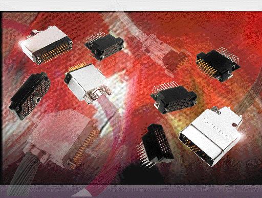
2 M Series Connectors Product Facts Most connectors intermateable with connectors made to MIL-C requirements Wide range of connector styles and sizes: standard c o n n e c t o r s (unloaded), posted c o n n e c t o r s ( p r e l o a d e d ) and special application connectors (unloaded) Complete line of accessory hardware for fastening, protecting, guiding, shielding, strain relief and keying A variety of contacts: signal, power, coaxial and posted versions many are interchangeable and can be intermixed in the same connector housing Full complement of application tooling for wire crimp and posted terminations hand tools, semiautomatic tooling and fully automatic machines provide highly reliable, low cost terminations to meet production requirements Need More Information? Call the Technical Support Center:. The Center is staffed with specialists well versed in all AMP products and application tooling. The Center can provide you with: Technical Support Catalogs Technical Documents Product Samples AMP FAX Service Product Information Faxed Immediately Authorized Distributor Locations Consult Tyco Electronics Corporation for latest design specifications. 1968, 1970, 1972, 1974, 1978, 19 85, , and 2001 by Tyco Electronics Corporation. All Rights Reserved. AMP, AMP FAX, AMPOMATOR, AMP-O-LECTRIC, AMP-O-MATIC, AMP-TAPETRONIC, CERTI-CRIMP, COAXICON, LGH, POWERBAND, PRO-CRIMPER, RAYCHEM, TERMI-POINT and TYCOare trademarks. Standard Housings Posted Connectors Special Application Connectors Other products, logos, and company names mentioned herein may be trademarks of their respective owners. 2
3 Table of Contents Product Facts Introduction , 5 Material Specifications Current Carrying Capabilities , 8 How to Use this Catalog Connector/Hardware Selection Guide (for Typical Applications) Cable-to-Cable Cable-to-Panel Contacts (Description of Types) Signal Contacts Type II, Crimp, Snap-In Type III+, Crimp, Snap-In; Posted; Solder Versions Power Contacts Type I, Crimp, Snap-In High Current Type II and Type III+ (Screw Machine, Crimp, Snap-In) Type XII, Crimp, Snap-In High Current Type XII (Screw Machine, Crimp, Snap-In) Coaxial Contacts Subminiature, Crimp, Snap-In, Size , 41 Miniature, Crimp, Snap-In, Size , 43 Standard Housings Introduction , 14, and 20-Positions , 34 and 36-Positions , and 50-Positions , and 104-Positions CF Positions (with Center Fastener) CF Positions (with Center Fastener) Posted Connectors Introduction , 14, 20 and 26-Positions , and 50 Positions , and 104-Positions and 160 CF Positions (with Center Fastener) , 59 15, 36 and 50 Positions (.200 [5.08] Grid) , 60 Special Application Connectors Introduction V.35 Special Application Connectors Introduction , 63 V.35 Printed Circuit Board Connectors V.35 Cable Connectors Positions, High Current Connector (UL Voltage Rating: 1800 V) CF Position Connector with Mixed Contacts (with Center Fastener) Positions, Connector with Mixed Contacts Positions, High Voltage Connector (UL Voltage Rating: 1800 V) Positions, High Voltage Connector (UL Voltage Rating: 1800 V) and 34-Positions, Grounding Blocks and Fastening Hardware Hardware Fastening Hardware Guiding Hardware Protective Hardware Strain Relief Hardware Keying Hardware Application Tooling , 91 Technical Documents , 93 Part Number Index , 95 3
4 Introduction AMP M Series connectors are one of the most versatile and complete pin and socket connector lines available today. From the basic molded plastic housing, a connector can be built up with a wide choice of contacts and hardware to serve in applications ranging from sophisticated computers, medical instrumentation and military ground support equipment to rugged truck transmissions. How this M Series catalog is divided The M Series catalog is divided into six categories: Application section Contacts/Tooling Standard Connector Housings Posted Connector Housings Special Application Connector Housings Hardware Following is a brief summary of each of the six categories. Knowing what you need to meet your application is made easy Eight applications have been illustrated with selection charts from pages 10 through 25. These charts will assist you to select the appropriate connector housing as well as the necessary hardware. Each base part number is listed in the numerical index on pages 94, 95 in order to find complete information about a particular part. Contacts of various types provide different functions in M Series connector housings Included are contacts for signal and power applications, for coaxial cable and posted versions for backpanel wiring. A full complement of application tooling is available to meet any production requirement for terminating the crimptype contacts and wiring posted contacts. A description of each contact type is presented on pages 26 through 29. Application tooling for these contacts is described on pages 90 and 91. Standard connectors Standard connectors are comprised of unloaded housings that accept a variety of crimp, solder and posted contacts. All standard connector housings will accept pins and/or sockets, permitting various combinations of contact loading. Standard connectors are described on pages 44 through 51. Posted connectors Posted connectors are preloaded with post-type contacts that accept TERMI-POINT Clip or wrap-type terminations. All posted connectors are described on pages 52 through 60. Special Application connectors Connectors for special application are available in the following configurations: V.35 High Current Mixed Contact Connectors High Voltage RFI/EMI Shielded Grounding Blocks Special Application Connectors are described on pages 61 through 77. The right hardware for the entire M Series connector line Hardware is available to provide fastening, protection, shielding, guiding, strain relief and keying capabilities for the entire M Series connector line. Application charts for properly selecting hardware are presented on pages 10 through 25. Detailed information on hardware is located on pages 78 through 89. 4
5 Introduction (Continued) What makes the M Series connector line so versatile and special for a wide variety of applications? Compatibility Most connectors intermateable with connectors made to M I L - C requirements. Wide range Choice of connector styles and sizes: standard connectors (unloaded), posted connectors (preloaded) and special application connectors. Complete line Full line of accessory hardware for fastening, protecting, guiding, strain relief and keying. Variety of contacts S i g n a l, power, coaxial, and posted versions many are interchangeable and can be intermixed in the same connector housing. Full complement of application tooling For wire crimp and posted terminations hand tools, semiautomatic tooling and fully automatic machines provide highly reliable, low cost terminations to meet production requirements. How to choose the appropriate connector/contact/ hardware combination Choosing the appropriate connector/contact/hardware combination is essential to the proper function of any AMP M Series connector. First, a customer must evaluate each individual application with regards to: wire size(s); number of circuits; available space; fastening methods; and needs for protection, shielding, guiding, strain relief and keying. Then, the customer must consider the following factors to make the appropriate selection of M Series connectors and related components. A Determine Connector Type This decision is based on the selected contact types, circuit density requirements and, if posted connectors are desired, in-plant production capabilities for wiring connectors using hand tools or semiautomatic tooling. Detailed specifications of the various M Series connectors are presented on the following pages: Standard connectors (pages 44 through 51), Posted connectors (pages 52 through 60), Special Application connectors (pages 61 through 77). B Determine Hardware This decision is based on the selected connector types, and the individual application requirements for fastening, protection, shielding, guiding, strain relief and keying. To assist customers in determining the proper hardware to use, hardware selection information has been formulated for each connector type. This information is located on pages 10 through 25. Complete specifications of each hardware component are presented in the Hardware section of the catalog (pages 78 through 89). C Determine Contact Type This decision is based on wire size(s) and reliability and cost requirements of an application, as well as the customer s in-plant production capabilities. Complete specifications, including accepted wire sizes and available platings of all pin and socket contacts, are presented in the Contacts section of the catalog (pages 30 through 43). Application tooling for crimp- and post-type contacts is presented on pages 90 and 91). 5
6 Material Specifications C o n t a c t s The material composition and construction of AMP contacts encompass varying price ranges and performance characteristics. Specific materials and available platings and plating thicknesses of each contact type are provided on individual contact pages in the Contact section (pages 30 thru 43). A brief description of each contact type is presented on pages 26 through 29. Also, typical performance data of M Series connectors and contacts is shown below. H o u s i n g s M Series connector housings are made of either diallyl phthalate (blue), general purpose phenolic (black) or polyester (black). Diallyl phthalate housings are molded of material per MIL-M-14, Type SDG. These housings are ideally suited for use where adverse environmental conditions are an important factor. Their advantages include exceptional stability; excellent resistance to acids, alkalies and solvents; low moisture absorption; and good dielectric strength. Phenolic housings are molded of material per MIL-M-14, Type CFG. The performance characteristics of these housings make them an excellent choice for applications in which exceptional resistance to acids, alkalies or solvents is not of prime concern. Polyester housings are molded from a high temperature thermoplastic material per ASTM D3220. Polyester housings provide the high temperature characteristics of diallyl phthalate and phenolic, but with a higher impact strength. H a r d w a r e A variety of materials such as plated steel, stainless steel and aluminum, are used in the construction of M Series connector hardware. This provides for the proper operation and durability of each hardware component, while offering a choice of economies to satisfy particular application requirements. The materials of each hardware component are specified on the individual hardware component pages in the Hardware section (pages 78 through 89). Performance Data Temperature Rating: Phenolic Housings, 55 C to +150 C Diallyl Phthalate Housings, 65 C to +125 C Polyester, 55 C to +130 C Flammability Ratings: UL94V-0 Dielectric Withstanding Voltage (at sea level): Type II Contacts, 1500 VAC, RMS Type III+ Contacts, 900 VAC, RMS Durability (Mating/Unmating): Types II and III+ Contacts, Gold Plated: 500 cycles; Types II and III+ Contacts, Bright Tin-Lead Plated: 50 cycles; Type I Contacts, Gold Plated: 100 cycles Note: For detailed information on the above performance data and further information on other performance data such as Insulation Resistance, Thermal Shock, Moisture Resistance, Vibration and Physical Shock, request AMPProduct Specification No Recognized under the Component Program of Underwriters Laboratories Inc. for 250 volts, File No. E28476 Certified by Canadian Standards Association, File No. LR
7 Current Carrying Capabilities The total current capacity of each contact in a given connector is dependent upon the heat rise resulting from the combination of electrical loads of the contacts in the connector arrangement and the maximum ambient temperature in which the connector will be operating. Caution must be taken to ensure that this combination of conditions does not cause the internal temperature of the connector to exceed the maximum operating temperature of the housing material. Several variables which must be considered when determining this maximum current capability for your application are: CONTACT CURRENT GUIDE Maximum Current (Amperes) Type XII Upgrade Size 8 Upgrade.125 POWERBAND Contact Size 8 Type XII Type I, Type II/III+ Upgrade Type III+, Type II, Type III+ Posted Size 20 Upgrade 20 DF Wire Size Larger wire will carry more current since it has less internal resistance to current flow and generates less heat. The wire also conducts heat away from the connector. Connector Size In general, with more circuits in a connector, less current per contact can be carried. Current Load Distribution Spreading those lines with greater current loads throughout the connector, particularly around the outer perimeter, will enhance heat dissipation. Ambient Temperature With higher ambient temperatures, less current can be carried. Current Rating Verification Can a contact rated at 10 amps carry 10 amps? Maybe yes, but probably not. The reason lies in the test conditions used to rate the contact. If these conditions do not adequately reflect the application conditions, the actual allowable current levels may be lower than specified levels. For example, many manufacturers, including Tyco, test a single contact in air. This gives an accurate measure of the basic current-carrying capacity of the contact. Use the contact alone in air and it can certainly carry 10 amperes. Use it in a multiposition connector surrounded by other current-carrying contacts or in high ambient temperatures, and the contact should carry less current. Similarly, as the contact ages and stress relaxation, environmental cycling, and other degradation factors take their toll, the contact s currentcarrying capacity decreases. A prudent design must set current levels for such end-ofdesign-life (EODL) conditions. Practical current-carrying capacity is not an absolute, but an application-dependent condition. New Method Simplifies Ratings To help the designer set the appropriate current level, Tyco has developed a method of specifying current-carrying capacity. This method takes into account the various application factors that influence current rating. The method can be summarized as follows: The contact is aged to EODL conditions by durability cycling, thermal cycling, and environmental exposure. The contact s resistance stability is verified. The current necessary to p r oduce the specified temperature rise is measured. This T-rise is usually 30 C. A rating factor is determined to allow derating of multiple contacts in the same housing and for different conductor sizes. Temperature One other factor influencing current levels is the maximum operating temperature, for example, 105 C. If the application has a high ambient temperature (over 75 C) the contact s T-rise is limited by the maximum operating temperature. For example, an application temperature of 90 C limits the contact T-rise to 15 C. Since current produces heat (the I 2 R law), the current must be lowered to limit the T-rise. A contact s T-rise depends not only on its I 2 R Joule heating, but also on its ability to dissipate the heat. Consider a contact in a multi-contact housing. Joule heating in multiple contacts will raise the local ambient temperature. Since the contact will not be able to dissipate its own heat as well by convection, the maximum T-rise will be realized at a lower current level. Consequently, the allowable current level must be lower to maintain an acceptable T-rise. For a given connector, the current level will be set by the loading density. A connector containing 50% current-carrying contacts will permit higher currents (per contact) than a connector will at 75% loading. The loading percentage assumes an even distribution of contacts within the housing. If all 10 contacts are grouped together in one section of a 20-position connector, the loading density may approach 100%. The Importance of EODL As stated, T-rise in a contact depends on both resistance and current. As it ages, a contact s resistance will increase. The contact designer will specify a maximum resistance for the contact, this level is the end-ofdesign-life resistance. Before the contact is tested for current, Tyco subjects it to a sequence of tests that exercises the major failure mechanisms and thereby simulates EODL conditions. Conditioning includes mating cycling, industrial mixed-flowing gases, humidity and temperature cycling, and vibration to sequentially introduce wear, corrosion, stress relaxation, and mechanical disturbance. 7
. This represents the maximum current capacity of the contact. The curve is usually flat up to 75 C ambient and then drops off.")
.")

8 Presentation Example of New Current Rating Format The presentation of currentcarrying capacity in AMP product specifications includes two parts: First, a base curve showing current levels versus T-rise for a single circuit and the largest wire size (See figure 1). This represents the maximum current capacity of the contact. The curve is usually flat up to 75 C ambient and then drops off. Up to 75 C, the 30 C T-rise limits the amount of current, and above 75 C the current must be reduced to keep the combination of ambient temperature and T-rise from exceeding the maximum operating temperature of 105 C. Next are rating factors; a table of multipliers to account for connector loading and for smaller wire sizes (See figure 2). The designer first determines the base current for the ambient conditions of the application; then multiplies this base current by the rating factors to find the current level for the application s loading factor and wire size. Practical Values The current-rating method gives designers practical values applicable to their applications. While the specified current levels for a contact may be lower than for other testing methods, they are more realistic and simplify the system design process. Spec-manship is replaced by a realistic assessment of the current-carrying capacity of a Connector/Contact Acceptability As previously stated, choosing the appropriate connector/contact combination is fundamental to the successful function of all connectors. The Selection Chart, shown at right, is designed to simplify your choice of connectors and their acceptable contacts. Once you have selected the wire size, currentcarrying capacity need, number of positions required, and the type of contacts needed in your choice of connector, refer to this matrix for a quick look at exactly what is acceptable in a given connector type. Note: Data is not typical of a specific M Series connector configuration. For specific current rating information based on % connector loading, contact Tyco Electronics. To demonstrate the method of specifying current, consider the following application conditions; an ambient temperature of 65 C, a 50% loading of contacts in the housing, and 20 AWG [0.6mm 2 ] wire. From Figure 1, the base current rating is 14 ampere with 18 AWG [0.8mm 2 ] wire. Figure 2, the rating factor for 50% loading and 20 AWG [0.6mm 2 ] wire is The specific rating for this applic a t i o n is the product of the base rating and the rating factor: 14 x 0.68 = 9.5 ampere Each of the contacts can carry 9.5 ampere. However, if the ambient temperature is 80 C the allowable T-rise becomes 25 C. The base current must be lowered to 12.8 ampere so that the 105 C maximum operating temperature is not exceeded. The current rating then becomes: 12.8 x 0.68 = 8.7 a m p e r e. contact under varying conditions of temperature, connector loading, and wire size. Specific current-carrying data based on EOL and % loading is available from Tyco Electronics Corporation. Please contact your local Sales Engineer or call Tyco Electronics Corporation. Contact Selection Chart Figure 1 Graph shows the relationship between base current, ambient temperature, and contact T-rise. Figure 2 Rating factors allow the base current to be adjusted for various connector loading and wire sizes. Connector High Current Posted High Current Sub-Mini Type Type I Type II Type II/III+ Type III+ Type III+ Type XII Type XII Mini-Coax Coax M Series M Series Special 8
9 How to Use the M Series Connector Catalog The information in this catalog has been arranged to assist the customer in selecting the connector and associated hardware that best satisfies their requirements. Four cable-to-cable and four cable-to-panel applications utilizing the various types of fastening, guiding and protective hardware have been illustrated on pages 10 through 25. After selecting the appropriate application to fit a particular requirement, refer to the indicated pages for component selection. Posted connectors and Special Application connectors can be substituted for Standard Connectors where indicated. Noted under each Special Application Connector is the standard size hardware used for that connector. Substitute into the appropriate column of the component selection charts. The main portion of the catalog is divided into five basic sections: contacts, standard connectors, posted connectors, special application connectors and hardware. These sections contain brief descriptions, dimensions and other technical information. The remainder of the catalog contains application tooling information, a technical documents list and a numerical index which references pages covering all cataloged part numbers. 9
10 Cable-to-Cable Application A Locking Springs Featured Hardware Strain Relief Clamps Locking Springs Pin Hoods Guide Hardware Pin Hoods Pins Housings Sockets Guide Hardware Strain Relief Clamps Component Description Number of Positions Plug Block Receptacle Block Phenolic STANDARD Plug Block HOUSINGS Receptacle Block Diallyl Phthalate Pages 44 to 51 Plug Block Polyester Receptacle Block STRAIN Long Nickel Plated Steel RELIEF Short CLAMPS Long Page 88 Stainless Steel Short Center Male GUIDE Center Female HARDWARE Stainless Steel Page 81 Corner Male Corner Female Male Nickel Plated Spring Steel LOCKING SPRINGS1 Page 80 Female Stainless Steel (Single Spring) Internal Open End Nickel Plated Steel PIN HOODS Internal Closed End Nickel Plated Steel Pages 82 and 83 External Closed End Al Iridite External Closed End Nickel Plated Steel 1Each part number contains two locking springs. Order one male and one female for each mated pair of connectors. 10
11 Cable-to-Cable (Continued) 1. Confirm that Application A (at left) most closely meets your requirements. (Other applications are shown on pages 12 through 25.) 2. Find the appropriate column for the number of positions required. 3. Select part numbers required for the application listed in the column below the number of positions. 3. If a part number is not listed for a particular item, it is not available. 3. If more than one part number is listed for a particular hardware item, choose the one which best fits your application. Special application housings may be substituted for these standard housings. See Special Application Section. This cable-to-cable application utilizes locking springs, strain relief clamps, a pin hood for pin protection and guide hardware. The 34 and 50 position connectors can be used with either center or corner guide hardware. If center guide hardware is used, an additional four 4-40 screws, nuts and lockwashers are required to secure the locking springs. Corner guides require four guide pins and four guide sockets for each mated pair of connectors. 4. Dimensional information is available on the indicated pages under description column. 5. Select Contacts: Type II (page 30), Type III+ (pages 31 through 35) or Subminiature Coaxial (pages 40, 41). Number of Positions CF 160 CF Component Description Plug Block Receptacle Block Phenolic Plug Block STANDARD Diallyl Phthalate Receptacle Block HOUSINGS Pages 44 to Plug Block Polyester Receptacle Block Long Nickel Plated Steel STRAIN Short RELIEF Long CLAMPS Stainless Steel Short Page Center Male Center Female GUIDE Stainless Steel HARDWARE Corner Male Page Corner Female Male Nickel Plated Spring Steel LOCKING SPRINGS Female Stainless Steel Page 80 Internal Open End Nickel Plated Steel Internal Closed End Nickel Plated Steel PIN HOODS External Closed End Al Iridite Pages 82 and 83 External Closed End Nickel Plated Steel 11
12 Cable-to-Cable (Continued) Application B Sockets Featured Hardware Strain Relief Clamps Pin Hoods Jackscrews Guide Hardware Guide Hardware Pin Hoods Pins Jackscrews Housings Strain Relief Clamps Component Description Number of Positions Plug Block Receptacle Block Phenolic STANDARD Plug Block HOUSINGS Receptacle Block Diallyl Phthalate Pages 44 to Plug Block Polyester Receptacle Block STRAIN Long Nickel Plated Steel RELIEF Short CLAMPS Long Page 88 Stainless Steel Short Fixed Male Stainless Steel Fixed Female Long-Long Male JACKSCREWS1 Long-Long Female Tip: Pages 78 and 79 Long Male Stainless Steel Long Female Body: Short-Short Male Die Cast Zinc Short-Short Female Center Male GUIDE Center Female HARDWARE Stainless Steel Page 81 Corner Male Corner Female Internal Open End Nickel Plated Steel PIN HOODS Internal Closed End Nickel Plated Steel Pages 82 and 83 External Closed End Al Iridite External Closed End Nickel Plated Steel 1Listed Jackscrews have 6-32 single lead threads. For corresponding Jackscrews with 6-32 double lead threads, refer to pages 78 and
13 Cable-to-Cable (Continued) 1. Confirm that Application B (at left) most closely meets your requirements. (Other applications are shown on pages and 14 through 25.) 2. Find the appropriate column for the number of positions required. 3. Select part numbers required for the application listed in the column below the number of positions. 3. If a part number is not listed for a particular item, it is not available. 3. If more than one part number is listed for a particular hardware item, choose the one which best fits your application. Special application housings may be substituted for these standard housings. See Special Application Section. This cable-to-cable application utilizes jackscrews, strain relief clamps and guide hardware. A pin hood is provided for pin protection. Sizes 6, 14, 20, 26, and 41 do not use guide hardware with this application. 4. Dimensional information is available on the indicated pages under description column. 5. Select Contacts: Type II (page 30), Type III+ (pages 31 through 35) or Subminiature Coaxial (pages 40, 41). Number of Positions CF 160 CF Component Description Plug Block Phenolic Receptacle Block STANDARD Plug Block Diallyl Phthalate HOUSINGS Receptacle Block Pages 44 to Plug Block Polyester Receptacle Block Long Nickel Plated Steel STRAIN Short RELIEF Long CLAMPS Stainless Steel Short Page Fixed Male Fixed Female Stainless Steel Long-Long Male Long-Long Female Tip: JACKSCREWS1 Long Male Stainless Steel Pages 78 and 79 Long Female Body: Short-Short Male Die Cast Zinc Short-Short Female Center Male Center Female GUIDE Stainless Steel HARDWARE Corner Male Page Corner Female Internal Open End Nickel Plated Steel Internal Closed End Nickel Plated Steel PIN HOODS External Closed End Al Iridite Pages 82 and External Closed End Nickel Plated Steel 13
14 Cable-to-Cable (Continued) Application C Locking Springs Sockets Featured Hardware Housings Shields (One-piece) Pin Hoods Locking Springs Guide Hardware Pin Hoods Pins Guide Hardware Shields Component Description Number of Positions Plug Block Receptacle Block Phenolic STANDARD HOUSINGS Plug Block Diallyl Phthalate Pages 44 to 51 Receptacle Block Plug Block Polyester Receptacle Block Two- Piece Long Al Anodized Zinc Plated Steel 180 Two- Piece Short Al Anodized Zinc Plated Steel Zinc Plated Cast Al SHIELDS 90 Two-Piece Long Pages 84 to Two-Piece Short 45 Two-Piece Short Nickel 45 Two-Piece Deep Plated 180 One-Piece Long Steel One-Piece Short One-Piece Short Center Male GUIDE Center Female HARDWARE Stainless Steel Page 81 Corner Male Corner Female LOCKING SPRINGS1 Male Nickel Plated Spring Steel Page 80 Female Stainless Steel Internal Open End Nickel Plated Steel PIN HOODS Internal Closed End Nickel Plated Steel Pages 82 and 83 External Closed End Al Iridite External Closed End Nickel Plated Steel 1Each part number contains two locking springs. Order one male and one female for each mated pair of connectors. 14
15 Cable-to-Cable (Continued) 1. Confirm that Application C (at left) most closely meets your requirements. (Other applications are shown on pages and 16 through 25.) 2. Find the appropriate column for the number of positions required. 3. Select part numbers required for the application listed in the column below the number of positions. 3. If a part number is not listed for a particular item, it is not available. 3. If more than one part number is listed for a particular hardware item, choose the one which best fits your application. 4. Dimensional information is available on the indicated pages under description column. 5. Select Contacts: Type II (page 30), Type III+ (pages 31 through 35) or Subminiature Coaxial (pages 40, 41). Special application housings may be substituted for these standard housings. See Special Application Section. This cable-to-cable application utilizes locking springs, one-piece shields, a pin hood for pin protection and guide hardware. The shields are available with both 180 and 90 cable exits. The 180 shields are available in a long version which provides pin protection in lieu of a pin hood. A short shield and a pin hood or a long shield can be used on one side only of a mated pair of connectors. The mating connector must use a short shield. The 34 and 50 position connectors can be used with either center or corner guide hardware. If center guides are used, an additional four 4-40 screws are required to secure the locking springs. If corner guides are used, an additional two 4-40 screws will be required to attach the shield. Corner guides require four guide pins and four guide sockets for each mated pair of connectors. Number of Positions CF 160 CF Component Description Plug Block Phenolic Receptacle Block STANDARD Plug Block Diallyl Phthalate HOUSINGS Receptacle Block Pages 44 to Plug Block Receptacle Block Polyester 180 Two- Al Anodized Piece Long Zinc Plated Steel Al Anodized 180 Two- Piece Short Zinc Plated Steel Zinc Plated Cast Al 90 Two-Piece Long SHIELDS 90 Two-Piece Short Pages 84 to Two-Piece Short Nickel 45 Two-Piece Deep Plated 180 One-Piece Long Steel 180 One-Piece Short One-Piece Short Center Male Center Female GUIDE Stainless Steel HARDWARE Corner Male Page Corner Female Male Nickel Plated Spring Steel LOCKING SPRINGS Female Stainless Steel Page 80 Internal Open End Nickel Plated Steel Internal Closed End Nickel Plated Steel PIN HOODS External Closed End Al Iridite Pages 82 and 83 External Closed End Nickel Plated Steel 15
16 Cable-to-Cable (Continued) Application D Sockets Featured Hardware Shields (Two-piece) Pin Hoods J a c k s c r e w s Strain Relief Clamps Guide Hardware Pin Hoods Pins Guide Hardware Strain Relief Clamps Jackscrews Housings Shields 16 Component Description Number of Positions Plug Block Receptacle Block Phenolic STANDARD Plug Block HOUSINGS Receptacle Block Diallyl Phthalate Pages 44 to 51 Plug Block Polyester Receptacle Block Two- Piece Long Al Anodized Nickel Plated Steel Two- Piece Short Al Anodized Nickel Plated Steel Nickel Plated Cast Al SHIELDS 90 Two-Piece Long Pages 84 to Two-Piece Short 45 Two-Piece Short Nickel 45 Two-Piece Deep Plated 180 One-Piece Long Steel 180 One-Piece Short 90 One-Piece Short STRAIN Long Nickel Plated Steel RELIEF Short CLAMPS Long Page 88 Stainless Steel Short Fixed Male Stainless Steel Fixed Female Long-Long Male JACKSCREWS1 Long-Long Female Tip: Pages 78 and 79 Long Male Stainless Steel Long Female Body: Short-Short Male Die Cast Zinc Short-Short Female Center Male GUIDE Center Female HARDWARE Stainless Steel Page 81 Corner Male Corner Female Internal Open End Nickel Plated Steel PIN HOODS Internal Closed End Nickel Plated Steel Pages 82 and 83 External Closed End Al Iridite External Closed End Nickel Plated Steel 1Listed Jackscrews have 6-32 single lead threads. For corresponding Jackscrews with 6-32 double lead threads, refer to pages 78 and 79.
17 Cable-to-Cable (Continued) 1. Confirm that Application D (at left) most closely meets your requirements. (Other applications are shown on pages and 18 through 25.) 2. Find the appropriate column for the number of positions required. 3. Select part numbers required for the application listed in the column below the number of positions. 3. If a part number is not listed for a particular item, it is not available. 3. If more than one part number is listed for a particular hardware item, choose the one which best fits your application. 4. Dimensional information is available on the indicated pages under description column. Special application housings may be substituted for these standard housings. See Special Application Section. This cable-to-cable application utilizes jackscrews, a twopiece short shield, a strain relief clamp, a pin hood for pin protection and guide hardware. Do not use a pin hood in combination with the shield for sizes 20, 26 and 41. A long shield may be used in lieu of pin hood for pin protection for all sizes except the 20 position. Shields are available with 180 cable exit and for the 50 through 104 position connectors, a 90 cable exit. Select the appropriate jackscrew length for the type of shield chosen as indicated by symbol ( ). 5. Select Contacts: Type II (page 30), Type III+ (pages 31 through 35) or Subminiature Coaxial (pages 40, 41). Number of Positions CF 160 CF Component Description Plug Block Phenolic Receptacle Block STANDARD Plug Block Diallyl Phthalate HOUSINGS Receptacle Block Pages 44 to Plug Block Polyester Receptacle Block Two- Al Anodized Piece Long Nickel Plated Steel Al Anodized Two- Piece Short Nickel Plated Steel Nickel Plated Cast Al Two-Piece Long SHIELDS Two-Piece Short Pages 84 to Two-Piece Short Nickel 45 Two-Piece Deep Plated 180 One-Piece Long Steel 180 One-Piece Short 90 One-Piece Short Long Nickel Plated Steel STRAIN Short RELIEF Long CLAMPS Stainless Steel Short Page Fixed Male Fixed Female Stainless Steel Long-Long Male Long-Long Female Tip: JACKSCREWS Long Male Stainless Steel Pages 78 and Long Female Short-Short Male Short-Short Female Center Male Center Female Corner Male Body: Die Cast Zinc GUIDE Stainless Steel HARDWARE Page Corner Female Internal Open End Nickel Plated Steel Internal Closed End Nickel Plated Steel PIN HOODS External Closed End Al Iridite Pages 82 and External Closed End Nickel Plated Steel 17
18 Cable-to-Panel Application E Locking Springs Featured Hardware Strain Relief Clamps Locking Springs Pin Hoods Guide Hardware Pin Hoods Guide Hardware Sockets Pins Housings Panel Strain Relief Clamps Component Description Number of Positions Plug Block Receptacle Block Phenolic STANDARD Plug Block HOUSINGS Receptacle Block Diallyl Phthalate Pages 44 to 51 Plug Block Polyester Receptacle Block STRAIN Long Nickel Plated Steel RELIEF Short CLAMPS Long Page 88 Stainless Steel Short Center Male GUIDE Center Female HARDWARE Stainless Steel Page 81 Corner Male Corner Female LOCKING SPRINGS1 Male Nickel Plated Spring Steel Page 80 Female Stainless Steel Internal Open End Nickel Plated Steel PIN HOODS Internal Closed End Nickel Plated Steel Pages 82 and 83 External Closed End Al Iridite External Closed End Nickel Plated Steel 1Each part number contains two locking springs. Order one male and one female for each mated pair of connectors. 18
19 Cable-to-Panel (Continued) 1. Confirm that Application E (at left) most closely meets your requirements. (Other applications are shown on pages and 20 through 25.) 2. Find the appropriate column for the number of positions required. 3. Select part numbers required for the application listed in the column below the number of positions. 3. If a part number is not listed for a particular item, it is not available. 3. If more than one part number is listed for a particular hardware item, choose the one which best fits your application. Special application housings and posted housings may be substituted for these standard housings. See Special Application and Posted Connectors Sections. This cable-to-panel application utilizes locking springs, strain relief clamps, a pin hood for pin protection and guide hardware. The 34 and 50 position connectors can be used with either center or corner guide hardware. If center guide hardware is used, an additional four 4-40 screws, nuts and lockwashers are required to secure the locking springs. Corner guides require four guide pins and four guide sockets for each mated pair of connectors. 4. Dimensional information is available on the indicated pages under description column. 5. Select Contacts: Type II (page 30), Type III+ (pages 31 through 35) or Subminiature Coaxial (pages 40, 41). Number of Positions CF 160 CF Component Description Plug Block Phenolic Receptacle Block STANDARD Plug Block Diallyl Phthalate HOUSINGS Receptacle Block Pages 44 to Plug Block Polyester Receptacle Block Long Nickel Plated Steel STRAIN Short RELIEF Long CLAMPS Stainless Steel Short Page Center Male Center Female GUIDE Stainless Steel HARDWARE Corner Male Page Corner Female Male Nickel Plated Spring Steel LOCKING SPRINGS Female Stainless Steel Page 80 Internal Open End Nickel Plated Steel Internal Closed End Nickel Plated Steel PIN HOODS External Closed End Al Iridite Pages 82 and 83 External Closed End Nickel Plated Steel 19
20 Cable-to-Panel (Continued) Application F Featured Hardware Strain Relief Clamps Pin Hoods Jackscrews Guide Hardware Pin Hoods Guide Hardware Pins Jackscrews Housings Sockets Panel Strain Relief Clamps Component Description Number of Positions Plug Block Receptacle Block Phenolic STANDARD Plug Block HOUSINGS Receptacle Block Diallyl Phthalate Pages 44 to 51 Plug Block Polyester Receptacle Block STRAIN Long Nickel Plated Steel RELIEF Short CLAMPS Long Page 88 Stainless Steel Short Fixed Male Stainless Steel Fixed Female Long-Long Male JACKSCREWS1 Long-Long Female Tip: Pages 78 and 79 Long Male Stainless Steel Long Female Body: Short-Short Male Die Cast Zinc Short-Short Female Center Male GUIDE Center Female HARDWARE Stainless Steel Page 81 Corner Male Corner Female Internal Open End Nickel Plated Steel PIN HOODS Internal Closed End Nickel Plated Steel Pages 82 and 83 External Closed End Al Iridite External Closed End Nickel Plated Steel 1Listed Jackscrews have 6-32 single lead threads. For corresponding Jackscrews with 6-32 double lead threads, refer to pages 78 and
21 Cable-to-Panel (Continued) 1. Confirm that Application F (at left) most closely meets your requirements. (Other applications are shown on pages and 22 through 25.) 2. Find the appropriate column for the number of positions required. 3. Select part numbers required for the application listed in the column below the number of positions. 3. If a part number is not listed for a particular item, it is not available. 3. If more than one part number is listed for a particular hardware item, choose the one which best fits your application. Special application housings and posted housings may be substituted for these standard housings. See Special Application and Posted Connectors Sections. This cable-to-panel application utilizes jackscrews, strain relief clamps and guide hardware. A pin hood is provided for pin protection. Sizes 6, 14, 20, 26, and 41 do not use guide hardware for this application. 4. Dimensional information is available on the indicated pages under description column. 5. Select Contacts: Type II (page 30), Type III+ (pages 31 through 35) or Subminiature Coaxial (pages 40, 41). Number of Positions CF 160 CF Component Description Plug Block Phenolic Receptacle Block STANDARD Plug Block Diallyl Phthalate HOUSINGS Receptacle Block Pages 44 to Plug Block Polyester Receptacle Block Long Nickel Plated Steel STRAIN Short RELIEF Long CLAMPS Stainless Steel Short Page Fixed Male Fixed Female Stainless Steel Long-Long Male Long-Long Female Tip: JACKSCREWS1 Long Male Stainless Steel Pages 78 and 79 Long Female Short-Short Male Short-Short Female Center Male Center Female Corner Male Body: Die Cast Zinc GUIDE Stainless Steel HARDWARE Page Corner Female Internal Open End Nickel Plated Steel Internal Closed End Nickel Plated Steel PIN HOODS External Closed End Al Iridite Pages 82 and External Closed End Nickel Plated Steel 21
22 Cable-to-Panel (Continued) Application G Featured Hardware Shields (One-piece) Pin Hoods Locking Springs Guide Hardware Pin Hoods Pins Locking Springs Guide Hardware Sockets Housings Panel Shields Component Description Number of Positions Plug Block Receptacle Block Phenolic STANDARD Plug Block HOUSINGS Receptacle Block Diallyl Phthalate Pages 44 to 51 Plug Block Polyester Receptacle Block Two- Piece Long Al Anodized Nickel Plated Steel 180 Two- Piece Short Al Anodized Nickel Plated Steel Nickel Plated Cast Al SHIELDS 90 Two-Piece Long Pages 84 to Two-Piece Short 45 Two-Piece Short Nickel 45 Two-Piece Deep Plated 180 One-Piece Long Steel One-Piece Short One-Piece Short Center Male GUIDE Center Female HARDWARE Stainless Steel Page 81 Corner Male Corner Female LOCKING SPRINGS1 Male Nickel Plated Spring Steel Page 80 Female Stainless Steel Internal Open End Nickel Plated Steel PIN HOODS Internal Closed End Nickel Plated Steel Pages 82 and 83 External Closed End Al Iridite External Closed End Nickel Plated Steel 1Each part number contains two locking springs. Order one male and one female for each mated pair of connectors. 22
23 Cable-to-Panel (Continued) 1. Confirm that Application G (at left) most closely meets your requirements. (Other applications are shown on pages and 24, 25.) 2. Find the appropriate column for the number of positions required. 3. Select part numbers required for the application listed in the column below the number of positions. 3. If a part number is not listed for a particular item, it is not available. 3. If more than one part number is listed for a particular hardware item, choose the one which best fits your application. 4. Dimensional information is available on the indicated pages under description column. Special application housings and posted housings may be substituted for these standard housings. See Special Application and Posted Connectors Sections. This cable-to-panel application utilizes locking springs, one-piece shields, a pin hood for pin protection and guide hardware. The shields are available with both 180 and 90 cable exits. The 180 shields are available in a long version which provides pin protection in lieu of a pin hood. Do not select a long shield and a pin hood. The 34 and 50 position connectors can be used with either center or corner guide hardware. If center guides are used, an additional four 4-40 screws are required to secure the locking springs. If corner guides are used, an additional two 4-40 screws will be required to attach the shield. Corner guides require four guide pins and four guide sockets for each mated pair. 5. Select Contacts: Type II (page 30), Type III+ (pages 31 through 35) or Subminiature Coaxial (pages 40, 41). Number of Positions CF 160 CF Component Description Plug Block Phenolic Receptacle Block STANDARD Plug Block Diallyl Phthalate HOUSINGS Receptacle Block Pages 44 to Plug Block Polyester Receptacle Block 180 Two- Al Anodized Piece Long Nickel Plated Steel Al Anodized 180 Two- Piece Short Nickel Plated Steel Nickel Plated Cast Al 90 Two-Piece Long SHIELDS 90 Two-Piece Short Pages 84 to Two-Piece Short Nickel 45 Two-Piece Deep Plated 180 One-Piece Long Steel 180 One-Piece Short 90 One-Piece Short Center Male Center Female GUIDE Stainless Steel HARDWARE Corner Male Page Corner Female Male Nickel Plated Spring Steel LOCKING SPRINGS Female Stainless Steel Page 80 Internal Open End Nickel Plated Steel Internal Closed End Nickel Plated Steel PIN HOODS External Closed End Al Iridite Pages 82 and 83 External Closed End Nickel Plated Steel 23
24 Cable-to-Panel (Continued) Application H Sockets Featured Hardware Shields (Two-piece) Pin Hoods Guide Hardware Jackscrews Pin Hoods Pins Guide Hardware Jackscrews Housings Panel Shields Component Description Number of Positions Plug Block Receptacle Block Phenolic STANDARD Plug Block HOUSINGS Receptacle Block Diallyl Phthalate Pages 44 to 51 Plug Block Polyester Receptacle Block Two- Piece Long Al Anodized Nickel Plated Steel Two- Piece Short Al Anodized Nickel Plated Steel Nickel Plated Cast Al SHIELDS 90 Two-Piece Long Pages 84 to Two-Piece Short 45 Two-Piece Short Nickel 45 Two-Piece Deep Plated 180 One-Piece Long Steel 180 One-Piece Short 90 One-Piece Short Fixed Male Stainless Steel Fixed Female Long-Long Male JACKSCREWS1 Long-Long Female Tip: Pages 78 and 79 Long Male Stainless Steel Long Female Body: Short-Short Male Die Cast Zinc Short-Short Female Center Male GUIDE Center Female HARDWARE Stainless Steel Page 81 Corner Male Corner Female Internal Open End Nickel Plated Steel PIN HOODS Internal Closed End Nickel Plated Steel Pages 82 and 83 External Closed End Al Iridite External Closed End Nickel Plated Steel 1Listed Jackscrews have 6-32 single lead threads. For corresponding Jackscrews with 6-32 double lead threads, refer to pages 78 and
25 Cable-to-Panel (Continued) 1. Confirm that Application H (at left) most closely meets your requirements. (Other applications are shown on pages 10 through 23.) 2. Find the appropriate column for the number of positions required. 3. Select part numbers required for the application listed in the column below the number of positions. 3. If a part number is not listed for a particular item, it is not available. 3. If more than one part number is listed for a particular hardware item, choose the one which best fits your application. 4. Dimensional information is available on the indicated pages under description column. Special application housings and posted housings may be substituted for these standard housings. See Special Application and Posted Connectors Sections. This cable-to-panel application utilizes jackscrews, a twopiece short shield, a strain relief clamp, a pin hood for pin protection and guide hardware. Do not use a pin hood in combination with the shield for sizes 20, 26 and 41. A long shield may be used in lieu of pin hood for pin protection for all sizes except the 20 position. Shields are available with 180 cable exit and for the 50 thru 104 position connectors, a 90 cable exit. 104 CF has 90 and 45 cable exits. 160 CF has 45 cable exit. Select the appropriate jackscrew length for the type of shield chosen as indicated by symbol ( ). 5. Select Contacts: Type II (page 30), Type III+ (pages 31 through 35) or Subminiature Coaxial (pages 40, 41). Number of Positions CF 160 CF Component Description Plug Block Receptacle Block Phenolic Plug Block STANDARD Diallyl Phthalate Receptacle Block HOUSINGS Pages 44 to Plug Block Polyester Receptacle Block Two- Al Anodized Piece Long Nickel Plated Steel Al Anodized Two- Piece Short Nickel Plated Steel Nickel Plated Cast Al Two-Piece Long SHIELDS Two-Piece Short Pages 84 to Two-Piece Short Nickel Two-Piece Deep Plated 180 One-Piece Long Steel 180 One-Piece Short 90 One-Piece Short Fixed Male Fixed Female Stainless Steel Long-Long Male Long-Long Female Tip: JACKSCREWS Long Male Stainless Steel Pages 78 and Long Female Short-Short Male Short-Short Female Center Male Center Female Corner Male Body: Die Cast Zinc GUIDE Stainless Steel HARDWARE Page Corner Female Internal Open End Nickel Plated Steel Internal Closed End Nickel Plated Steel PIN HOODS External Closed End Al Iridite Pages 82 and External Closed End Nickel Plated Steel 25
26 Signal Contacts Type III+, Crimp, Snap-In, Size 16 Precision formed pin and socket contacts in Size 16. They are used in M Series, Special M Series, G Series, Metrimate, Metrimate Drawer, and CPC Series 1 and 4 connectors. Contacts feature a high normal force which provides a low resistance in significant applications such as dry circuit signal conditions. Mating entry is closedended to prevent damage from stubbing due to misalignment. Stainless steel spring provides superior normal force and retention in the housing. AMP proprietary gold plating process is designed so that specified plating thicknesses are controlled on the inside of the socket, which is the critical contact mating area. The contacts are formed from brass. Single contact rating is 13 amperes at 30 C T-Rise. See page 31 for product details. Type III+, Solder Type, Size 16 As with the crimp snap-in Type III+, these precision formed solder-type contacts are also used in M Series, Special M Series, Metrimate, Metrimate Drawer, and CPC Series 1 and 4 connectors. Contacts feature a high normal force which provides a low resistance in significant applications, such as dry circuit conditions. A preformed wire barrel accepts both stranded and solid wire, while the preformed insulation barrel provides strain relief for various wire insulation thicknesses. Mating entry is closed-ended to prevent damage from stubbing due to misalignment. A stainless steel spring provides superior normal force and retention in the housing. AMP proprietary gold plating process is designed so that specified plating thicknesses are controlled on the inside of the socket, which is the critical contact area. Single contact current rating is 13 amperes at 30 C Temperature Rise. See pages 34 and 35 for product details. Type III+, Solder Tab, Size 16 A companion contact style to the crimp snap-in and soldertype, the Type III+ Solder Tab is compatible with the same AMP connector families, and features high normal forces to provide a low resistance in significant applications. A precrimped solder tab with slot accepts various sizes of solid and stranded wire. Mating entry is closed-ended to prevent stubbing due to misalignment. A stainless steel spring provides superior normal force and retention in the housing. AMP proprietary gold plating process is designed so that specified plating thicknesses are controlled on the inside of the socket, which is the critical contact area. Single contact current rating is 13 amperes at 30 C Temperature Rise. See page 35 for product details. 26
27 Signal Contacts (Continued) Type III+, Posted Version, Size 16 The last member of the Type III+ family of contacts, the posted version is compatible with M Series, Special M Series, Metrimate, Metrimate Drawer, and CPC Series 1 connectors. Precision formed, they are pre-crimped to various post configurations including those that accept TERMI-POINT Clip or wire-wrap type terminations. Contacts feature high normal force which provides a low resistance in significant applications. Mating entry is closed-ended to prevent damage from stubbing due to misalignment. A stainless steel spring provides superior normal force and retention in the housing. AMP proprietary gold plating process is designed so that specified plating thicknesses are controlled on the inside of the socket, which is the critical contact mating area. Contacts are formed from brass. Single contact current rating is 13 amperes at 30 C Temperature Rise. See page 32 for product details. Type II, Crimp, Snap-In, Size 16 Precision screw-machined pin and socket contacts, they are used in M Series, Special M Series, G Series, Metrimate, Metrimate Drawer, and CPC Series 1 and 4 connectors. Contacts feature high normal force which provides a low resistance in significant applications such as dry circuit signal conditions. Mating entry is closedended to prevent damage from stubbing due to misalignment. A stainless steel spring provides superior normal force and retention in the housing. The contact bodies are machined from solid brass. Single contact current rating is 13 amperes at 30 C Temperature Rise. See page 30 for product details. 27
28 Power Contacts Type I, Crimp, Snap-In, Size 12 Precision screw-machined pin and socket, Size 12 contacts, they are used in Special M Series and G Series connectors, and are inserted into the same cavities as Miniature Coaxial contacts. These contacts feature a high normal force which provides a low resistance in significant applications. Mating entry is closed-ended to prevent damage from stubbing due to misalignment. Beryllium copper springs are used to provide contact normal force and are assisted by a stainless steel hood which provides anti-overstress assurance. Single contact current rating is 23 amperes at 30 C Temperature Rise. See page 36 for product details. Type XII, Crimp-Type Precision formed male and female contacts used in CPC Series 3 and 4, Special M Series and G Series connectors, these contacts offer a low cost power option which provides additional applied cost savings when terminated with semiautomatic application equipment. The contact body is made from 100% copper, which provides for excellent conductivity. Spring characteristics are derived from a captive stainless steel spring which assists the dual cantilever spring members of the female contact. Single contact current rating is 35 amperes at 30 C Temperature Rise. See page 38 for product details. High Current Upgrades Precision screw-machined pin and socket contacts have increased current capability. All upgraded contacts use the high amperage Louvertac contact band. The design of this contact allows for increased current in the same form factor. For example, Type II/Type III+ upgraded contacts increase the current from 13 amperes free air to 23 amperes free air at a 30 C Temperature Rise. See pages 37 and 39 for product details. 28
29 Coaxial Contacts Subminiature, Crimp, Snap-In, Size 16 Precision screw-machined pin and socket, Size 16 contacts, they are used in M Series, Special M Series, and CPC Series 1 and 4. They provide cost effective solutions in applications where mixtures of signal, power, and coaxial cable terminations are desired. The contact outer shell is made from brass, while the center pin conductor is beryllium copper, and the socket is brass. Both the pin and socket center conductor are gold plated for maximum corrosion resistance and minimum contact resistance. The retention spring is stainless steel, while the ferrule is tin-lead plated copper. Contact design offers application of coaxial cable, shielded conductors, and twisted pair wire with a voltage rating of up to 200 VRMS, and a current rating of 1.0 ampere at 30 C Temperature Rise. See pages 40 and 41 for product details. Miniature, Crimp, Snap-In, Size 12 Precision screw-machined, Size 12 pin and socket contacts, they are used in Special M Series and G Series connectors. They provide cost effective solutions in applications where a mixture of signal, power, and coaxial cable terminations is desirable. Contact body and center wire conductor are made from brass, and are gold plated for maximum corrosion resistance and minimum contact resistance. The retention spring is beryllium copper, and the ferrule is tin-lead plated copper. Contact design offers application of coaxial cable, shielded conductors, and twisted pair wire with a voltage rating of up to 325 VRMS, and a current rating of 7.5 amperes at 30 C Temperature Rise. See pages 42 and 43 for product details. 29
30 Signal Contacts Type II, Crimp, Snap-In 1.087±.010 [27.61±0.25] Pin.472± [11.99±0.13].062±.001 [1.57±0.03] Dia..107 [2.72] Max. Dia. Pin Spring Pin Body Socket Material Contact Body Brass Retention Spring Stainless steel Spring.795±.010 [20.19±0.25] Finish Contact Body [ ] gold over [ ] nickel. Gold thickness controlled on socket O.D. Socket Body Socket Technical Documents Product Specification Application Specification Contact Size 16 Pin Diameter.062 [1.57] (Test Current, 13 Ampere) Tooling Part No. Wire Size Ins. Tape Mounted Loose Piece Contact Tape Mounted Loose Piece Range Dia. Contact No.2 Contact No. Color Dies for Dies for AWG [mm2] Range1 Pin Socket Pin Socket Code AMP-TAPETRONIC Pneumatic Hand Machine Tool Tool* * Red/Red -1* ** or ** Red/Red 1* ** Yellow/Red 1* ** Yellow/Red or ** No. Ins. (Two) (Two) Support Blue ** or ** ** or ** Blue/Blue No. Ins. ** ** Support, ,6 Blue/Blue or ** Violet/Blue No. Ins. ** ** Support,6, ,6, or ** 1Overall insulation crimp diameter, including crimp barrel, must not exceed.125 [3.18]. 2For AMP-TAPETRONIC Machine No , order contacts by Tape Mounted Contact No., plus packaging code IM REEL (5000 parts per reel). 3Grounding pin is used to provide a make-first/break-last condition when mating and unmating connector halves. 4Use turret TH502 ( ) with hand tool Use turret TH501 ( ) with hand tool Pin length is.630±.005 [16.002±.127] on these two pins. *Use hand actuated Power Unit Part No or foot actuated Power Unit Part No Both units require C Head Die Set Adapter Part No and an Adapter Holder Part No (with ratchet) or Part No (without ratchet). Request Catalog for more information on the 626 Pneumatic Tool System. **Commercial PRO-CRIMPERII Hand Tool for field repair use only. Does not use Hand Tool Single contact, free-air test current is not to be construed as contact rating current. Use only for testing. Refer to contact current carrying capability information on page 7. Insertion Tool Part No (for insulation diameters.070 [1.78] or less). Extraction Tool Part No (Instruction Sheet ) 30
![Signal Contacts (Continued) Type III+, Crimp, Snap-In [.0625.0020 +.0010 [1.588 +0.025 Dia. 0.051] Pin Body Spring, Stainless Steel Spring, Stainless Steel Pin.390 [9.91] Min.](/docs-images/82/84892652/images/31-1.jpg "Ferrule, Brass, Nickel Flash.113 [2.87] Max. Dia. Material Contact Body Brass or phosphor bronze Retention Spring Stainless steel Finish See chart.")
31 Signal Contacts (Continued) Type III+, Crimp, Snap-In [ [ Dia ] Pin Body Spring, Stainless Steel Spring, Stainless Steel Pin.390 [9.91] Min. Ferrule, Brass, Nickel Flash.113 [2.87] Max. Dia. Material Contact Body Brass or phosphor bronze Retention Spring Stainless steel Finish See chart. Socket Pin Related Product Data Application Tooling Pages 90, 91 Technical Documents Application Specification Product Specification Contact Size 16 Pin Diameter.062 [1.57] (Test Current, 13 Ampere).530±.010 [13.46±0.25] Wire Size Ins. Strip Form Loose Piece Tooling Part No. Range Dia. Contact Contact No. Contact No. Finish Loose Piece Strip Form AWG mm 2 Range Pin Socket Pin Socket Hand Tool A p p l i c a t o r s Gold/Nickel *** or *** Sel. Gold/Nickel or *** Bright Tin-Lead Gold/Nickel *** Sel. Gold/Nickel Gold/Nickel Sel. Gold/Nickel *** Bright Tin-Lead *** Gold/Nickel or or Sel. Gold/Nickel * *** Sel. Gold/Nickel Bright Tin-Lead *** Gold/Nickel or or Sel. Gold/Nickel * *** Sel. Gold/Nickel Bright Tin-Lead *** Sel. Gold/Nickel or *** Sel. Gold/Nickel or *** Bright Tin-Lead Gold/Nickel *** or or Sel. Gold/Nickel *** Sel. Gold/Nickel Bright Tin-Lead S or *** Gold/Nickel or or Sel. Gold/Nickel * *** Sel. Gold/Nickel Bright Tin-Lead *** Gold/Nickel or *** Sel. Gold/Nickel Sel. Gold/Nickel *** Bright Tin-Lead or Sel. Gold/Nickel *** 1Overall insulation crimp diameter, including crimp barrel, must not exceed.125 [3.18] [ ] gold in the mating area over [ ] min. nickel [ ] gold in the mating area, with gold flash on remainder, over [ ] min. nickel [ ] gold in the mating area, with gold gradient on remainder, over [ ] min. nickel. 5Contacts can only be used in Metrimate, Series 1 (Arr ), Series 4 (Arr M, 23-16M, 23-22M), and VDE connectors. 6To use with the 626 Pneumatic Tool System: remove the crimping head from the Straight Action Hand Tool (SAHT) Assembly, order SAHT Adapter Part No , Adapter Holder Part No (with ratchet) or (without), and Power Unit PartNo (hand actuated) or (foot actuated). SStandard reeling of strip form contacts. *Commercial PRO-CRIMPER II hand tool for field repair only. Note: Die Set can be adapted for use with the 626 Pneumatic Tool System. Socket Single contact, free-air test current is not to be construed as contact rating current. Use only for testing. Refer to contact current carrying capability information on page 7. Insertion Tool Part No (for insulation diameters.070 [1.78] or less), No (for insulation diameters.090 [2.29] max.). Extraction Tool Part No (Instruction Sheet ) ***Call the at for Automatic Machine Applicator Part Numbers. 31
![Signal Contacts (Continued) Type III+, Posted (Replacement Contacts, See Note Below).062 [1.58] Dia. Ref. Pin.025 [0.64] Point of Gold Plating Thk. Measurement.100 [2.54] Pin Spring Stainless Steel.](/docs-images/82/84892652/images/32-0.jpg "025±.001 [0.64±0.03] Material Socket Contact Body and Post Brass Retention Spring Stainless steel Body Brass.525 [13.34] Post Brass Finish See chart. Socket Contact Size 16 Pin Diameter.062 [1.")
32 Signal Contacts (Continued) Type III+, Posted (Replacement Contacts, See Note Below).062 [1.58] Dia. Ref. Pin.025 [0.64] Point of Gold Plating Thk. Measurement.100 [2.54] Pin Spring Stainless Steel.025±.001 [0.64±0.03] Material Socket Contact Body and Post Brass Retention Spring Stainless steel Body Brass.525 [13.34] Post Brass Finish See chart. Socket Contact Size 16 Pin Diameter.062 [1.57] (Test Current, 13 Ampere) Loose Piece Contact No. Termination Post Contact Method Configuration Finish 3 Termination High Post 2 Termination High Post 1 Termination High Post Pin Socket Pin Socket Pin Socket Sel. Gold/Nickel x.025 Gold/Nickel x 0.64 Bright Tin-Lead Wrap-Type.045 x.045 Sel. Gold/Nickel x 1.14 Bright Tin-Lead x x 1.57 TERMI-POINT.031 x.062 Clip 0.79 x 1.57 Sel. Gold/Nickel Sel. Gold/Nickel Gold flash over [ ] nickel on entire contact, with [ ] gold to a distance of.200 [5.08] from mating end. Gold thickness controlled on socket O.D [ ] gold over [ ] nickel on contact body. Gold thickness controlled on socket O.D. Posts plated tin-lead over copper. Extraction Tool Part No (Instruction Sheet ) Insertion Tool Part No Note: These contacts are used as replacement contacts for all posted connectors. Single contact, free-air test current is not to be construed as contact rating current. Use only for testing. Refer to contact current carrying capability information on page 7. 32
33 Signal Contacts (Continued) Type III+, Crimp, Snap-In Contact Size 16 Pin Diameter.062 [1.57] Grounding Pin (make first - break last) Material and Finish Contact Body Copper alloy, plated tin or gold Spring Stainless steel Related Product Data Application Tooling Pages 90, 91 Wire Size Range Ins. Grounding Pin Part No. Strip Form Loose Piece Dia. Contact Applicator Hand Tool [mm2] AWG Finish Range1 Strip Form Loose Piece Part No. Part No Tin-Lead or Sel. Gold/Nickel * Bright Tin-Lead *** or or or Sel. Gold/Nickel *** * Tin-Lead *** or or or Sel. Gold/Nickel *** * 1Overall insulation crimp diameter, including crimp barrel, must not exceed.125 [3.18]. 4Gold flash over [ ] min. nickel on entire contact, with [ ] gold in contact area. 5To use with the 626 Pneumatic Tool System: remove the crimping head from the Straight Action Hand Tool (SAHT) Assembly, order SAHT Adapter Part No , Adapter Holder Part No (with ratchet) or (without), and Power Unit Part No (hand actuated) or (foot actuated). *Commercial PRO-CRIMPER II hand tool for field repair only. Note: Die Set can be adapted for use with the 626 Pneumatic Tool System. ***Call the at for Automatic Machine Applicator Part Numbers. Extraction Tool Part No
34 Signal Contacts (Continued) Type III+, Solder Versions Solder-Type (with Preformed Wire Barrel/Insulation Support) Spring, Stainless Steel 3.90 [9.91] Min [ ] Dia [1.588 ] Pin Body, Brass [27.56] Max. Pin Localized Plate Area.200 [5.08] Min. Pin Socket.825 [20.96] Max. Material Contact Body and Tab Brass Retention Spring Stainless steel Finish See chart on Page ±.010 [13.46±0.25] Socket 34
35 Signal Contacts (Continued) Type III+, Solder Versions (Continued) Spring, Stainless Steel Solder Tab.390 [9.91] Min. Pin [ ] [1.588 ] Pin Body, Brass.794±.010 [20.17±0.25].020 [0.51] Localized Plate Area.200 [5.08] Min [28.24] Max..365 [9.27] Max. Pin Socket Spring Stainless Steel.120 [3.05].058 [1.47] Ferrule, Brass, Nickel Flash Body Brass Solder Post Brass.105 [2.67].865 [21.97].365 [9.27] Max. Material Contact Body and Tab Brass Retention Spring Stainless steel Finish See chart..530±.010 [13.46±0.25] Socket Contact Size 16 Pin Diameter.062 [1.57] (Test Current, 13 Ampere) Wire Size Loose Piece Range Contact Contact No. Finish AWG [mm2] Pin Socket Gold/Nickel Gold/Nickel Solder Duplex Tab Bright Tin-Lead [ ] gold in mating area over [ ] nickel. 2Duplex plated [ ] gold in mating area over [ ] nickel on contact body; bright tin-lead on solder tab. 3Bright tin-lead on entire contact. Note: These contacts can be used in Multimate contact cavities of all connector housings. Single contact, free-air test current is not to be construed as contact rating current. Use only for testing. Refer to contact current carrying capability information on page 7. Extraction Tool Part No (Instruction Sheet ) 35
![Power Contacts Type I, Crimp, Snap-In.150 [3.81] Dia..953 [24.21] Ref..663 [16.84] Max..449 [11.40] Pin.222 Dia. Max. [5.64] Pin.094 ±.001 [2.39 ±.025 ] Dia..150 [3.81] Dia..560 [14.25] Max.](/docs-images/82/84892652/images/36-1.jpg "Socket Accommodates.094±.001 [2.39±.025] Dia. Pin.222 Dia. Max. [5.64].843 [21.41] Ref. Socket Material Contact Body Bronze Retention Spring Beryllium copper Finish Contact Body.000030 [0.")
![00076] gold over.000050 [0.00127] nickel. Gold thickness controlled on socket O.D.](/docs-images/82/84892652/images/36-2.jpg "Retention Spring Nickel plated Related Product Data Application Tooling Pages 90, 91 Technical Documents 108-10108 Product Specification 114-10037 Application Specification Size 12 Pin Diameter.")
36 Power Contacts Type I, Crimp, Snap-In.150 [3.81] Dia..953 [24.21] Ref..663 [16.84] Max..449 [11.40] Pin.222 Dia. Max. [5.64] Pin.094 ±.001 [2.39 ±.025 ] Dia..150 [3.81] Dia..560 [14.25] Max. Socket Accommodates.094±.001 [2.39±.025] Dia. Pin.222 Dia. Max. [5.64].843 [21.41] Ref. Socket Material Contact Body Bronze Retention Spring Beryllium copper Finish Contact Body [ ] gold over [ ] nickel. Gold thickness controlled on socket O.D. Retention Spring Nickel plated Related Product Data Application Tooling Pages 90, 91 Technical Documents Product Specification Application Specification Size 12 Pin Diameter.094 [2.39] (Test Current, 23 Ampere) Wire Size Loose Piece Tooling Part No. Range Contact No. Dies for Hand AWG [mm2] Pin Socket Pneumatic Tool Tool* *Use hand actuated Power Unit Part No or foot actuated Power Unit Part No Both units require C Head Die Set Adapter Part No and an Adapter Holder Part No (with ratchet) or Part No (without ratchet). Request Catalog for more information on the 626 Pneumatic Tool System. Single contact, free-air test current; not to be construed as contact rating current. Use only for testing. Refer to contact current carrying capability information, page 7. Extraction Tool Part No (Instruction Sheet ) 36
, CMC (Circular Metal-Shell Connector), G Series, M Series, Econoseal Metrimate Square Grid and Drawer Connector housings.")
37 High Current Upgrade Type II and Type III+, Size 16 The Multimate features of the High Current Size 16 contact have been designed to fit into the existing AMP Connectors such as CPC (Circular Plastic Connector), CMC (Circular Metal-Shell Connector), G Series, M Series, Econoseal Metrimate Square Grid and Drawer Connector housings. An initial T-Rise test in free air has shown a 23 amp capability with a 30 T-Rise. The contact may be crimped onto 14 AWG wire with an AMP hand tool P/N Use turret TH502 ( ) for the pin and turret TH501 ( ) for the socket. Power Contacts (Continued) Standard Type II Socket (Page 30) Standard Type III + Socket (Page 31) High Current Size 16 Socket Part No Standard Type II Pin (Page 30) Standard Type III + Pin (Page 31) High Current Size 16 Pin Part No Material Pin Body Leaded brass Socket Body Copper alloy Louvertac Band Beryllium copper Retention Spring Stainless steel Finish Body Silver Louvertac Band Gold Current Rating for 30 C Temperature Rise 100% Energized 6 Circuit Connector (Wire-to-Wire) Extraction Tool Part No (Instruction Sheet ) Current-Carrying Capacity. The graph shows current-carrying capacity versus temperature rise for a fully energized 6 position Metrimate Square Grid plug P/N and receptacle P/N These initial representative amperage ratings were conducted with 14 AWG wires that were 2 feet long. Notes: 1. High Current contacts with Louvertac bands are not intermateable with any other contact. 2. Additional information on CPC and CMC connectors is available in Tyco Electronics Catalog No Additional information on G Series connectors is available in Tyco Electronics Catalog No Additional information on M Series connectors is available in Tyco Electronics Catalog No Additional information on Metrimate connectors is available in Tyco Electronics Catalog No Additional information on Econoseal connectors is available in Tyco Electronics Catalog No Additional information on LGH connectors is available in Tyco Electronics Catalog No
![Power Contacts (Continued) Type XII, Precision Formed, Crimp, Snap-In.615 [15.62] Material Copper.230 [5.84] Max. Finish A Tin-lead B.000030 [0.00076] selective gold over.000030 [0.00076] nickel C.](/docs-images/82/84892652/images/38-0.jpg "000100 [0.00254] silver plated contacts with lubricant added Male.230 [5.84] Max..978 [24.84] Ref. Test Current Rating Silver or Gold 35 amperes Tin Lead 15 amperes.287±.006 [7.29±0.152] Male.027 [0.")
![686] Ref. Single contact, free-air test current; not to be construed as contact rating current. Use only for testing. Refer to contact current carrying capability information, page 7..637 [16.18].](/docs-images/82/84892652/images/38-3.jpg "185 [4.7] Related Product Data Application Tooling Pages 90, 91 Technical Documents Pages 92, 93.085 [2.16].200 [5.08] Min..287 [7.29].230 [5.84] Max. 1.500 [38.1] Ref. Female.230 [5.84] Max..027 [0.")
38 Power Contacts (Continued) Type XII, Precision Formed, Crimp, Snap-In.615 [15.62] Material Copper.230 [5.84] Max. Finish A Tin-lead B [ ] selective gold over [ ] nickel C [ ] silver plated contacts with lubricant added Male.230 [5.84] Max..978 [24.84] Ref. Test Current Rating Silver or Gold 35 amperes Tin Lead 15 amperes.287±.006 [7.29±0.152] Male.027 [0.686] Ref. Single contact, free-air test current; not to be construed as contact rating current. Use only for testing. Refer to contact current carrying capability information, page [16.18].185 [4.7] Related Product Data Application Tooling Pages 90, 91 Technical Documents Pages 92, [2.16].200 [5.08] Min..287 [7.29].230 [5.84] Max [38.1] Ref. Female.230 [5.84] Max..027 [0.686] Ref [32.18] Ref..015 [0.38] Cutoff (Loose Piece Only) Extraction Tool Part No Female Strip Form Contact Part Nos. Loose Piece Tooling Wire Size Ins. Heavy Duty Contact Heavy Duty Die Set for Range1 Dia. Contact Standard*** Miniature*** Part Nos. Miniature Hand Tool Range Finish Male Female Applicator or 626 Pneumatic AWG mm2 Male Female Male Female Tool System A ,7 and and B *** and ,7 5C A B *** C Wire strip length.281 [7.14]. 2Ground contact. 3Die insert PartNo is for crimping 16 AWG [ mm2] wire. 4Die insert PartNo is for crimping AWG [2-3 mm2] wire. 5Recommended for high current/vibration applications where fretting corrosion is a problem. 7Die Set requires C Head Adapter Part No ; Adapter Holder Part No (with ratchet) or (without); and Power Unit Part No (hand actuated) or (foot actuated). Extraction Tool Part No ***Call the at for Automatic Machine Applicator Part Numbers. 38
, CMC (Circular Metal-Shell Connector), G Series, and M Series housings. An initial T-Rise test in free air has shown a 60 amp capability with a 30 T-Rise with 8 gage wires.")
 Cable-to-Cable Standard Type XII Socket")
39 High Current Upgrade Type XII, Crimp, Snap-In The Multimate features of the High Current Type XII contact have been designed to fit into the existing AMP Connectors such as CPC (Circular Plastic Connector), CMC (Circular Metal-Shell Connector), G Series, and M Series housings. An initial T-Rise test in free air has shown a 60 amp capability with a 30 T-Rise with 8 gage wires. The contact may be crimped onto 8 AWG wire with a Daniels Hand Tool M310 or AMP P/N and Positioner TP1068S or AMP P/N Material Body Copper alloy Louvertac Band Beryllium copper Retention Spring Stainless steel Finish Body Silver Louvertac Band Gold Power Contacts (Continued) Cable-to-Cable Standard Type XII Socket (Page 38) High Current Type XII Socket Part No Current Rating for 30 C Temperature Rise 100% Energized 3 Circuit Connector (Wire-to-Wire) Standard Type XII Pin (Page 38) High Current Type XII Pin Part No Extraction Tool Part No Current-Carrying Capacity. The graph shows current-carrying capacity versus temperature rise for a fully energized 3 position CPC plug P/N and receptacle P/N These initial representative amperage ratings were conducted with 8 AWG wires that were 3 feet long. Notes: 1. High Current contacts with Louvertac bands are not intermateable with any other contact. 2. Additional information on CPC and CMC connectors is available in Tyco Electronics Catalog No Additional information on G Series connectors is available in Tyco Electronics Catalog No Additional information on M Series connectors is available in Tyco Electronics Catalog No Additional information on LGH connectors is available in Tyco Electronics Catalog No
40 Coaxial Contacts Subminiature, Crimp, Snap-In, Size [25.65] Ref. Pin Pin.650 [16.51] Ref. Socket [ ] Dia..250 [6.35] A ±.003 ±.076 Dia. Socket 0.112±.005 [2.845±.127] Dia. Ferrule Part No A [3.05].120 Dia. Part No [5.969] Max. Ferrule Part No A.123 [3.12] Dia [2.134] [2.184] Dia..250 ±.008 [6.35 ±.203 ] Ferrule Part No ±.003 [2.82 ±.076 ] Dia. 40 Material Outer Shell Brass per MIL-C-50 Center Conductor Beryllium copper per QQ-C-533 (Pin); Brass per QQ-B-626 (Socket) Inner Dielectric Polypropylene Retention Spring Stainless steel per QQ-S-766 Ferrule Copper per QQ-C-576 or ASTM-B-152 ( ) Finish Outer Shell, Center Conductor See charts Ferrule Tin-lead per MIL-T Selection Chart for Coaxial Cable Loose Piece Cable Size Contact Contact No. (RG/U) Finish Pin Socket 178, 196 Gold/Nickel Gold/Copper Gold/Nickel Gold/Copper Gold/Nickel 196 Gold/Copper (Double Braid) Gold/Nickel Gold/Copper , 188, 316 Gold/Nickel Gold/Copper Gold/Nickel Gold/Copper Gold/Nickel 174 Gold/Copper (Double Braid) Gold/Nickel Gold/Copper , 187 Gold/Nickel Gold/Copper Gold/Nickel Gold/Copper Gold/Nickel 187 Gold/Copper (Double Braid) Gold/Nickel Gold/Copper Gold/Nickel Gold/Copper Gold/Nickel Gold/Copper Ferrule Part No. Tooling Part No. Die Inserts for Hand Tool Hand or Pneumatic Tool* Tool *Use hand actuated Power Unit Part No or foot actuated Power Unit Part No Both units require C Head Die Set Adapter Part No and an Adapter Holder Part No (with ratchet) or Part No (without ratchet). Request Catalog for more information on the 626 Pneumatic Tool System. Extraction Tool Part No
41 Coaxial Contacts (Continued) Subminiature, Crimp, Snap-In, Size 16 (Continued) Selection Chart for Twisted Pair and Shielded Wire AWG Wire Size [mm2] Contact Finish Tooling Part No. Loose Piece Contact No. Ferrule Die Inserts for Part No. Hand Tool Hand Pin Socket or Pneumatic Tool* Tool Gold/Nickel (Twisted Pair, Solid) Gold/Copper Gold/Nickel (Twisted Pair, Solid) Gold/Copper (Twisted Pair, Stranded 7 Str.,.0050 [0.13] Dia.) (Twisted Pair, Solid or Stranded 7 Str [0.16] Dia.) Gold/Nickel Gold/Copper1 Gold/Nickel1 Gold/Copper Gold/Nickel Gold/Copper1 (Shielded,.075 [1.91] Max. O.D.) Gold/Nickel Gold/Copper or or [ ] gold over [ ] nickel outer shell and socket center conductor; [ ] gold over [ ] copper pin center conductor [ ] gold over [ ] nickel outer shell and socket center conductor; [ ] gold over [ ] copper pin center conductor. *Use hand actuated Power Unit Part No or foot actuated Power Unit Part No Both units require C Head Die Set Adapter Part No and an Adapter Holder Part No (with ratchet) or Part No (without ratchet). Request Catalog for more information on the 626 Pneumatic Tool System. Note: A ferrule is required for each pin and socket. Extraction Tool Part No
![Coaxial Contacts (Continued) Miniature, Crimp, Snap-In, Size 12.865 [21.97] Ref..005 [0.127] Max..231 Ref. Dia. [5.87].171±.005 [4.35±0.127] Dia..199 [5.05] Dia. Pin 1.118 [28.](/docs-images/82/84892652/images/42-0.jpg "4] Ref. Pin Socket.040±.002 [1.02±0.05].226 Ref. Dia. [5.75] Over Sleeve.199 [5.05] Dia. Ferrule Dust Cap Retention Spring Part No.")

42 Coaxial Contacts (Continued) Miniature, Crimp, Snap-In, Size [21.97] Ref..005 [0.127] Max..231 Ref. Dia. [5.87].171±.005 [4.35±0.127] Dia..199 [5.05] Dia. Pin [28.4] Ref. Pin Socket.040±.002 [1.02±0.05].226 Ref. Dia. [5.75] Over Sleeve.199 [5.05] Dia. Ferrule Dust Cap Retention Spring Part No Socket Material Outer Shell Brass per MIL-C-50 Center Conductor Brass per QQ-B-626 Inner Dielectric Polymethylpentene Retention Spring Beryllium copper per QQ-C-533 Ferrule Copper per QQ-C [10.80] Ref. Ferrule Finish Outer Shell, Center Conductor See charts on next page Retention Spring Nickel per QQ-N-290 Ferrule Tin-lead per MIL-T Extraction Tool Part No
43 Coaxial Contacts (Continued) Miniature, Crimp, Snap-In, Size 12 (Continued) Selection Chart for Coaxial Cable Cable Size (RG/U) Contact Finish Loose Piece Contact No. Pin Socket Ferrule Part No. Tooling Part No. Die Inserts for Hand Tool Hand or Pneumatic Tool* Tool 55, 55A, 55B Gold/Nickel , 142, 223 Gold/Copper , 58A, 58B, 58C Gold/Nickel Gold/Copper , 179A, 187, Gold/Nickel Gold/Copper , 180A, 195, Gold/Nickel Gold/Copper , 178A, 196 Gold/Nickel Gold/Nickel Gold/Copper Gold/Nickel Double Braid Gold/Nickel Double Braid Gold/Copper Special.125,.100,.066,.012DB Gold/Nickel Selection Chart for Twisted Pair Wire Size AWG [mm2] Max. Loose Piece Tooling Part No. Ins. Dia. Contact Contact No. Ferrule Die Inserts for (Two Wires Finish Part No. Hand Tool Hand Combined) Pin Socket or Pneumatic Tool* Tool Gold/Nickel1 (Solid) Gold/Nickel (Stranded) Gold/Copper Gold/Nickel1 (Solid or Stranded) Selection Chart for Shielded Wire Shielded Wire AWG No. 22 NAS-702, Class A 22 MIL-C-7078A, Type II 22 NAS-702, Class B Contact Finish Loose Piece Contact No. Pin Socket Ferrule Part No. Tooling Part No. Die Inserts for Hand Tool Hand or Pneumatic Tool* Tool Gold/Nickel Gold/Nickel Gold/Copper Selection Chart for Various Manufacturers Cables Cable Size Dielectric Cable Contact O.D. (Max.) O.D. Range Braid Finish Type/AWG [mm2] Loose Piece Contact No. Pin Socket Ferrule Part No. Tooling Part No. Die Inserts for Hand Tool Hand or Pneumatic Tool* Tool Brand-Rex T209A AWG Single Gold/Nickel Brand-Rex Gold/Nickel T5788A Single 26 AWG Gold/Copper RAYCHEM 0030D1314 Army Ord Single Gold/Nickel AWG [ ] gold over [ ] nickel [ ] gold over [ ] copper. *Use hand actuated Power Unit Part No or foot actuated Power Unit Part No Both units require C Head Die Set Adapter Part No and an Adapter Holder Part No (with ratchet) or Part No (without ratchet). Request Catalog for more information on the 626 Pneumatic Tool System. Note: A ferrule and retention spring ( ) are required for each pin and socket. 43
44 Standard Housings Standard connectors are furnished as unloaded housings that have Multimate contact cavities for accepting Type II, Type III+, and subminiature COAXICON crimp-type contacts, as well as Type III+ solder-type and posted contacts. All Multimate contacts are interchangeable in the same housing cavity. Standard connector housings are available in sizes ranging from 6 thru 160 positions. They mate with each other, as well as posted connectors of a corresponding size for hand tool and semiautomatic machine wiring. See Posted Connector section. 44
45 Standard Housings (Continued) 6 Position.688 [17.48].054 [1.37].580 [14.73].412 [10.46].206 [5.23].016 [0.41] R. 1.00±.020 [25.40±0.51] [ ].131±.002 Dia. [3.33±0.05].365 [9.27].915 [23.24].093 [2.36] R 4 Plc..120 [3.05] Dia. 2 Holes.548± [13.92±0.25] [17.48].130 [3.30] Dia. Recommended Panel Cutout Plug Housing Phenolic Part No Diallyl Phthalate Part No ±.015 [4.75±0.38] Receptacle Housing Phenolic Part No Diallyl Phthalate Part No Position.937 [23.8].054 [1.37].829 [21.06].472 [11.99].236 [5.99].016 [0.41] R ± [ ± 0.51].168 [4.27] Ref..220±.005 [5.59±0.13].300 [7.62].133 [3.38].129 [3.28] Dia..915 [23.24].120 [3.08] Dia. 2 Holes.937 [23.80].440±.010 [11.18±0.25].075 [1.91].150 [3.81].130 [3.30] Dia. Recommended Panel Cutout Plug Housing Phenolic Part No Position.130 [3.30].365 [9.27] Receptacle Housing Phenolic Part No Diallyl Phthalate Part No [1.37].472 [11.99].236 [5.99].440±.010 [11.18±0.25].300 [7.62].915 [23.24].093 R [2.36].016 [0.41] R [31.75] [29.01] 1.560±.020 [39.62±0.51] [31.75] ±.010 [28.19 ±0.25 ].130 [3.30] Dia. Recommended Panel Cutout Plug Housing Phenolic Part No Diallyl Phthalate Part No Receptacle Housing Phenolic Part No Diallyl Phthalate Part No Notes: 1. All housings accept Type II, Type III+, and Subminiature COAXICON contacts. 2. Pins and/or sockets may be used in any housing. 3. Dimensions are ±.005 [0.127]. 4. Housing cavity identification are mirror image. 45
46 Standard Housings (Continued) 26 Position.592 [15.04].296 [7.52].016 [0.41] R..560±.010 [14.22±0.25].365 [9.27].915 [23.24].075 [1.91] A [ ] 1.630±.020 [41.40±0.51].131 [3.33].129 [3.28] B.150 [3.81].100 [2.54].130 [3.30] Dia. Recommended Panel Cutout Plug Housing (Shown).130 [3.30] 34 Position.118 [3.00].790 [20.01].161 [4.09].468 [11.89].131 [3.33].129 [3.28].915 [23.24].750±.010 [19.05±0.25].016 [0.41] R. A [36.83] B 2.000±.020 [50.80±0.51].130 [3.30] Dia. (4 Holes).468 [11.89] Recommended Panel Cutout.130 [3.3] Dia. or.218 [5.54] Dia. is required when jackscrews are used. Plug Housing (Shown).365 [9.27] 2 Plc. 36 Position.177 [4.48].016 [0.41] R..468 [11.89].130 [3.30] Dia. (4 Holes).780 [19.81].365 [9.27] 2 Plc..915 [23.24].468 [11.89].010 [0.25] ±.020 [65.91 ±0.51 ] [51.43] A [57.94] 1.983±.010 [50.37±0.25] [10.43].790 [20.07].128 [3.25] Recommended Panel Cutout R Plug Housing (Shown)
47 Standard Housings (Continued) 26, 34 and 36 Positions (Continued) Related Product Data Dimensions Page Position.550 [13.97] No. of Housing Plug Dimension Receptacle Dimension Pos. Material Part Number A Part Number B 26 Phenolic Diallyl Phthalate Phenolic (Modified) (Modified) Polyester Diallyl Phthalate Phenolic Notes: 1. All housings accept Type II, Type III+, and Subminiature COAXICON contacts. 2. Pins and/or sockets may be used in any housing. 3. Dimensions are ±.005 [0.127]. 4. Housing cavity identification are mirror image. 5. Versions also available with notch for robotic assembly. Contact Tyco Electronics Corporation..275 [6.99].016 [0.41] R..915 [23.24].120 [3.05] Dia..440±.010 [11.18±0.25] [58.98] [55.88] [58.72].133 [3.38].129 [3.28] Dia ±.020 [68.25±0.51] [1.55] [3.30] Dia. Recommended Panel Cutout Plug Housing Phenolic Part No Diallyl Phthalate Part No ±.020 [6.10±0.51].365 [9.27] Receptacle Housing Phenolic Part No Diallyl Phthalate Part No Position.128 [3.25].161 [4.09].790 [20.01].395 [10.03].016 [0.41] R..750 ±.010 [19.05 ±0.25 ].365 [9.27].915 [23.24].468 [11.89] [57.94] [51.44] ±.020 [65.91 ±0.51 ].133 [3.38].129 [3.28] Dia [ ].130 [3.3] Dia..130 or [3.30] Dia..218 [5.54] Dia. (4 Holes).468 is required when [11.89] jackscrews are used. Recommended Panel Cutout Plug Housing Phenolic Part No Diallyl Phthalate Part No Receptacle Housing Phenolic Part No Diallyl Phthalate Part No
48 Standard Housings (Continued) 50 Position.327 [8.31].500 [12.70].140 [3.56].011±.001 [0.28±0.03].365 [9.27].468 [11.89] [51.44] [57.94] Mating Face [50.37] ±.008 [57.94 ±0.20 ] 2.595±.010 [65.91±0.25].016 [0.41] R..156±.005 [3.96±0.13] Dia..195 [4.95].766 [19.46] [29.34] Recommended Panel Cutout.128 [3.25].766 ±.008 [19.46 ±0.20 ].915 [23.24] Plug Housing Phenolic Part No (Mating face contact cavities numbered left to right.) 50 Position.327 [8.31].500 [12.70].140 [3.56].011±.001 [0.28±0.03].365 [9.27].766±.008 [19.46±0.20] [57.94] Mating Face ±.008 [57.94 ±0.20 ] [51.44] [50.37] 2.595±.010 [65.91±0.25].016 [0.41] R..156±.005 [3.96±0.13] Dia..195 [4.95].766 [19.46] [29.34] Recommended Panel Cutout.128 [3.25] 1.110±.010 [28.19±0.25].915 [23.24] Plug Housing Phenolic Part No (Mating face contact cavities numbered right to left.) 48
49 Standard Housings (Continued) 75 Position.327 [8.31] [ ].156 [3.96] Dia. (4 Holes).766 [19.46].365 [9.27].915 [23.24] 1.110±.010 [28.19±0.25].016 [0.41] R [57.94] [51.44].128 [3.25] 2.595±.020 [65.91±0.51].133 [3.38].129 [3.28] Dia [57.94].195 [4.95].766 [19.46] [29.34].140 [3.56].120 [3.05] Dia. Recommended Panel Cutout Plug Housing Phenolic Part No Diallyl Phthalate Part No Receptacle Housing Phenolic Part No Diallyl Phthalate Part No Position.130 [3.30] Dia. or.218 [5.54] Dia [40.13] [ ].438 [11.13].016 [0.41] R..875 [22.22] Ref..365 [9.27] [ ].375±.015 [9.53±0.38] R [60.32] [54.99] 2.750±.010 [69.85±0.25].133 [3.38].129 [3.28] Dia [60.32].105 [2.67].353 [8.97].875 [22.22].156 [3.96] Dia. (4 Holes).218 [5.54] diameter is required when jackscrews are used. Recommended Panel Cutout Plug Housing Phenolic Part No Receptacle Housing Phenolic Part No Notes: 1. All housings accept Type II, Type III+, and Subminiature COAXICON contacts. 2. Pins and/or sockets may be used in any housing. 3. Dimensions are ±.005 [0.127]. 4. Housing cavity identification are mirror image. 49
50 Standard Housings (Continued) 104 CF Position (with Center Fastener) [29.77].812 [20.62].150±.005 [3.81±0.13].915±.020 [23.24±0.51].230±.005 [5.84±0.13] 1.130±.010 [28.70±0.25].812 [20.62].150 [3.81] [73.02] [63.5] [55.58].172 [4.37] R..812 [20.62].281 [7.14] Dia..531 [13.49] [31.75] 2.83±.010 [71.86±0.25] 2.50 [63.50].075 [1.31].175 [4.44].500 [12.70].143 [3.63] Dia. (4 Holes) [63.50].165 [4.19].130 [3.30] Recommended Panel Cutout Plug Housing [31.62] [32.13] [63.50].350±.020 [8.89±0.51] (Deep from Back Face) 1/4-26UNF-2B [74.68] [75.18].133 [3.38].129 [3.28] Dia..895 [22.73].935 [23.75] Receptacle Housing Plug Housing Part No. Receptacle Housing Part No. Center Fastener Diallyl Diallyl Description Length Phenolic Phthalate Polyester Phenolic Phthalate Polyester T Handle Slotted Hex Slotted Hex Notes: 1. All housings accept Type II, Type III+, and Subminiature COAXICON contacts. 2. Pins and/or sockets may be used in any housing. 3. Dimensions are ±.005 [0.127]. 4. Housing cavity identification are mirror image. 50
51 Standard Housings (Continued) 160 CF Position (with Center Fastener) [47.42] [29.82].500 [12.70] [105.56] Ref..915 [23.24].365 [9.27] 1.826±.010 [46.38±0.25] [70.99] [60.30] [53.21].125 [3.18] R ±.010 [60.30±0.25].165 [4.19] Ref ±.010 [69.85±0.25] Recommended Panel Cutout.155 [3.94] Dia. (4 Holes).010 [0.25].012 [0.31] Plug Housing Phenolic Part No Diallyl Phthalate Part No ±.010 [46.38±0.25] 2.750±.010 [69.85±0.25] 2.374±.010 [60.30±0.25].365 [9.27].915 [23.24] Receptacle Housing Phenolic Part No Diallyl Phthalate Part No Notes: 1. All housings accept Type II, Type III+, and Subminiature COAXICON contacts. 2. Pins and/or sockets may be used in any housing. 3. Dimensions are ±.005 [0.127]. 4. Housing cavity identification are mirror image. 51
52 Posted Connectors Posted connectors are furnished preloaded with Size 16, posted contacts (as shown on page 32) and are specifically designed to be wired with hand tools and semiautomatic machines. The cavity centerline spacing is too close to accommodate the heads and mandrels of fully automatic machines. Post configurations of the preloaded contacts are available for accepting TERMI-POINT Clip and wrap-type terminations. Posted connector housings are made of black phenolic or diallyl phthalate and are available in sizes ranging from 6 thru 104 positions. They will mate with correspondingly sized standard connector (except.200 [5.08] grid) housings loaded with Size 16 crimptype contacts. It is not recommended to mate two posted connectors. Since the preloaded posted contacts are rigid in the housing, mating two posted connectors, particularly of the larger sizes, would be difficult. Posted connectors can be substituted for standard connectors in the Connector/ Hardware Selection Charts, pages 10 to 25. Tyco does not recommend the use of shields or strain relief clamps with posted connectors because of the potential of shorting. 52
53 Posted Connectors (Continued) 6 Position.054 [1.37].412 [10.46].206 [5.23].365 [9.27] A.016 [0.41] R [14.73] [17.48] 1.000±.020 [25.40±0.51].130 [3.30] Dia. Recommended Panel Cutout.915 [23.24] Plug Assembly 14 Position.054 [1.37].472 [11.99].236 [5.99].258 [6.55] A [21.06] [23.80].016 [0.41] R ±.020 [31.75±0.51].130 [3.30] Dia. Recommended Panel Cutout.300 [7.62] 2 Plc..915 [23.24].440±.010 [11.18±0.25] Plug Assembly Receptacle Assembly 20 Position.472 [11.99].054 [1.37].236 [5.99].016 [0.41] R..258 [6.55] A [31.75] [29.01] ± [ ± ].130 [3.30] Dia. Recommended Panel Cutout.390 [7.62] 2 Plc..915 [23.24] Plug Assembly 53
54 Posted Connectors (Continued) 26 Position.592 [15.04].296 [7.52].016 [0.41] R. A [33.32] [28.24] 1.630±.020 [41.40±0.51] [3.30] Dia..300 [7.62] [2.54].915 [23.24] Recommended Panel Cutout Plug Assembly ± [ ± ] A 1.630±.020 [41.40±0.51].300 [7.62].915 [23.24] Receptacle Assembly ± [ ± ] Plug and Receptacle Assemblies No. of Termination Post A Contact Plug Assembly Receptacle Assembly Pos. Method Configuration Dimension Finish Part No. Part No. 6 Wrap Type.025 x x Sel. Gold/Nickel Wrap Type x Sel x Gold/Nickel Wrap Type.025 x x Sel. Gold/Nickel TERMI-POINT Clip.031 x x Sel. Gold/Nickel Gold flash over [ ] nickel on entire contact, with [ ] gold to a distance of.200 [5.08] from mating end. Posts are plated tin-lead over copper. Notes: 1. Posted connectors listed above have black phenolic housings. 2. Replacement contacts are shown on page These posted connectors mate with standard connector housings shown on pages
55 Posted Connectors (Continued) 34 Position.468 [11.89].915 [23.24].750 ±.010 [19.05 ±0.25 ].075 [1.91] [42.85] 2.000±.020 [50.80±0.51].150 [3.81] Plug Assembly.365 [9.27] 2 Plc. A.790 [20.07].395 [10.03].118 [3.00].161 [4.09].468 [11.89].365 [9.27] A [42.84] ±.020 [50.80 ±0.51 ].275 [6.99].016 [0.41] R [23.24] Dia. [ ] -.000] Holes [.468 [11.89] [ or ] Receptacle Assembly.750 ±.010 [19.05 ±0.25 ].218 [5.54] diameter is required when jackscrews are used. Recommended Panel Cutout 55
56 Posted Connectors (Continued) 50 Position.128 [3.25].161 [4.09].790 [20.01].395 [10.03] A.016 [0.41] R [57.94] [51.44] 2.593±.020 [65.86±0.51].130 [3.30] Dia. (4 Holes).468 [11.89].130 [3.30] Dia. or.218 [5.54] Dia..915 [23.24] Plug Assembly A.750±.010 [19.05±0.25] Recommended Panel Cutout.218 [5.54] diameter is required when jackscrews are used ±.020 [65.91 ±0.51 ] Plug and Receptacle Assemblies.250 [6.35] 4 Plc..915 [23.24] Receptacle Assembly.750±.010 [19.05±0.25] 56 No. of Termination Post A Contact Plug Assembly Receptacle Assembly Pos. Method Configuration Dimension Finish Part No. Part No. 34 Wrap Type x Sel. Gold/Nickel x Sel. Gold/Nickel Wrap Type x Sel. Gold/Nickel x Sel. Gold/Nickel Gold flash over [ ] nickel on entire contact, with [ ] gold to a distance of.200 [5.08] from mating end. Posts are plated tin-lead over copper. Notes: 1. Posted connectors listed above have black phenolic housings. 2. Replacement contacts are shown on page These posted connectors mate with standard connector housings shown on pages 46 and 47.
57 Posted Connectors (Continued) 75 Position [29.34].766 [19.46] [19.46] [4.95].365 [3.56] [9.27] A [57.94] [51.44] 2.750±.010 [69.85±0.25].016 [0.41] R..327 [8.31].500 [12.70].156 [3.96] Dia. (4 Holes) Recommended Panel Cutout.128 [3.25].218±.015 [5.54±0.38].915 [23.24] Receptacle Assembly 1.110±.010 [28.19±0.25] 104 Position.130 [3.30] Dia. or.218 [5.54] Dia..156 [3.96] Dia. (4 Holes) [40.13].790 [20.01] A.016 [0.41] R [60.32] [54.99] 2.750±.010 [69.85±0.25].105 [2.67].353 [8.97].875 [22.22] Recommended Panel Cutout.438 [11.13].300 [7.62] 2 Plc..915 [23.24] 1.110±.010 [28.19±0.25].218 [5.54] diameter is required when jackscrews are used. Receptacle Assembly Receptacle Assemblies No. of Termination Post A Contact Receptacle Assembly Pos. Method Configuration Dimension Finish Part No. 75 Wrap-Type.025 x x Sel. Gold/Nickel Wrap-Type.025 x x Sel. Gold/Nickel Gold flash over [ ] nickel on entire contact, with [ ] gold to a distance of.200 [5.08] from mating end. Posts are plated tin-lead over copper. Notes: 1. Posted connectors listed above have black phenolic housings. 2. Replacement contacts are shown on page These posted connectors mate with standard connector housings shown on page
![Posted Connectors with Center Fastener 104 CF Position (with Center Fastener) 1.172 [29.77].812 [20.62] A.172 [4.37] R. 2.875 [73.02] 2.500 [63.50] 2.188 [55.58] 2.950±.010 [74.93 ±0.25].365 [9.27].](/docs-images/82/84892652/images/58-1.jpg "150 [3.81].500 [12.70] Recommended Panel Cutout.143 [3.63] Dia. (4 Holes) 1.250 ±.010 [31.75 ±0.25].915 ±.020 [23.24 ±0.")
58 Posted Connectors with Center Fastener 104 CF Position (with Center Fastener) [29.77].812 [20.62] A.172 [4.37] R [73.02] [63.50] [55.58] 2.950±.010 [74.93 ±0.25].365 [9.27].150 [3.81].500 [12.70] Recommended Panel Cutout.143 [3.63] Dia. (4 Holes) ±.010 [31.75 ±0.25].915 ±.020 [23.24 ±0.51] Receptacle Assembly (With Posted Socket Contacts) 104 CF Position (with Center Insert).812 [20.62].143 [3.63] Dia. (4 Holes) [31.75].150 [3.81].230 [5.84] A [73.02] [55.58].172 [4.37] R [63.50] ±.010 [74.93±0.25].365 [9.27] 2.500±.015 [63.50±0.03] 160 CF Position (with Jackscrew Socket) [29.77].500 [12.70] ±.010 [46.38 ±0.25].365 [9.27].915 [23.24].276 ±.010 [7.01 ±0.25] Plug Assembly (With Posted Pin Contacts) A [29.82] ±.015 [69.97 ±0.38] 2.375±.010 [60.32±0.25] 58 Receptacle Assembly (With Posted Pin Contacts)
59 Posted Connectors, with Center Fastener (Continued) Receptacle Assembly No. of Pos. Termination Method Post Configuration.025 x.025 (Black) CF Wrap-Type 0.64 x CF Wrap-Type Housing Receptacle Mating Plug Material A Contact Assembly Assembly (Color) Dimension Finish Part No. Part No..659 Phenolic Sel. Gold/Nickel Page 50 Sel. Gold/Nickel Diallyl Phthalate.261 (Blue) x.025 Diallyl Phthalate x 0.64 (Blue) 6.63 Sel. Gold/Nickel Sel. Gold/Nickel (Page 51) 1Gold flash over [ ] nickel on entire contact, with [ ] gold to a distance of.200 [5.08] from mating end. Posts are plated tin-lead over copper. 2Gold flash over [ ] nickel on entire contact, with [ ] gold to a distance of.250 [6.53] from mating end. Posts are plated tin-lead over copper. Extraction Tool Part No Note: Replacement contacts (Type III+ posted) are shown on page 32. Posted Connectors,.200 [5.08] Grid 15 Position.365 [9.27] Related Product Data Part Number See chart on Page ±.010 [27.43±0.25].256 [6.52].200 [5.08] [33.33] [41.40].200 [5.08].915 [23.24].215 [5.46] When Fully Seated Forward Plug Assembly (With Posted Pin Contacts).285 [7.24].570 [14.48] 59
60 Posted Connectors,.200 [5.08] Grid (Continued) 36 Position.468 [11.89].173 [4.39].016 [0.41] R 4 Plc ] or [ [ ].300 [7.62].780 [19.81] [51.44] [57.94] 2.595±.020 [65.91±0.51] [ Plc. ] Dia. R.407 [10.34].815 [20.70].218 [5.54] diameter is required when jackscrews are used..365 [9.27].915 [23.24] Recommended Panel Cutout Plug Assembly (With Posted Pin Contacts) 50 Position.327 [8.31].500 [12.70].140 [3.56].300 [7.62] 1.110±.010 [28.19±0.25].016 [0.41] R [57.94] [51.44] 2.595±.020 [65.91±0.51] [ ] Dia. 4 Holes.195 [4.95].766 [19.45] [29.33].128 [3.25] Recommended Panel Cutout Plug Assemblies.365 [9.27].915 [23.24] Plug Assembly (With Posted Pin Contacts) 60 Material and Finish Housing Phenolic per MIL-M-14, Type CFG; color, black Contacts Brass per MIL-C-50; selective [ ] gold over [ ] nickel plated (gold plating per MIL-G-45204, nickel plating per QQ-N-290) No. of T e r m i n a t i o n P o s t P o s t C o n t a c t Plug Assembly Mates with Receptacle Assembly P o s. M e t h o d C o n f i g u r a t i o n L e n g t h F i n i s h Part Number Part Number 1 5 W r a p - T y p e.025 x Sel. Gold/Nickel x T E R M I - P O I N T.031 x Sel. Gold/Nickel C l i p 0.79 x Gold flash over [ ] nickel on entire contact with [ ] gold to a distance of.200 [5.08] from mating end. Posts are plated tin-lead over copper. Post length will accommodate up to 3 terminations. Extraction Tool Part No Refer to page 32 for contact specifications (Type III+, Size 16). Mating receptacle block using crimp, snap-in contacts for 36-Position Plug Assembly, order Part No Mating receptacle block using crimp, snap-in contacts for 50-Position Plug Assembly, order Part No Refer to the appropriate column of Application Chart for Hardware Selection Page 10 through Page 25. N o t e : 36 position connector uses standard 50 position hardware. 50 position connector uses standard 75 position hardware.
61 Special Application Connectors Special Application Connectors are available in the following configurations: V.35 Shallow Block High Current Mixed High Voltage RFI/EMI Shielded Grounding Blocks V.35 Connector The 34 position V.35 Connector is fully assembled and ready for placement on a printed circuit board. They are also available in kit form for cable assembly. These AMP V.35 connectors meet the requirements of for CCITT V.35 interfacing. High current connectors a r e designed for applications requiring up to 25 amperes of current. They are available in 12-position male and female housings which have rectangular contact cavities for accepting Type XII c o n t a c t s. Mixed connectors a r e d e s i g n e d for applications that require intermixing signal, power and/or coaxial circuits in the same connector housing. Housings are available in 15-, 16-, 29 CF (center fastener) and 42-position sizes and, depending upon the specific configuration, will accept Multimate contacts, Type I and Miniature, Standard and Twin Standard COAXICON contacts. The rectangular contact cavities accept Type XII contacts. High voltage connectors a r e designed for high voltage applications using Multimate contacts. The cavity centerline spacings and the silo construction of the contact cavities increase the current creepage path for higher voltage ratings. Housing sizes include 20 and 28 positions. RFI/EMI shielding kits provide shielding capabilities a g a i n s t radio frequency and electromagnetic interferences. Special 104-position h o u s i n g s accept Multimate contacts and are especially designed for use with shielding hardware. These shielding kits cannot be used with the standard 104-position connector housings. Grounding blocks are ideally suited for aircraft applications, where shielded cable is to be grounded to an airframe. The ground wires of shielded cables are pigtailed off with ferrules and are crimped to Size 16 s o c k e t contacts. The contacts are loaded into a standard 14- or p o s i t i o n connector housing. This connector then can be mated to the grounding block which is fastened to the aircraft frame. Grounding blocks have Size 16 screw-machined p i n contacts which are staked, r i v- eted and soldered into the L-shaped metal bracket. The bracket has fixed jackscrew receptacles that will accept the special turnable jackscrews fastened to the mating socket connector half. 61


62 M Series V.35 Special Application Connectors Product Facts Meets requirements of for CCITT V.35 interface Pcb connectors fully assembled, right-angle and vertical mount Mounting bracket secures pcb connector to board Pcb connectors preloaded with Size 16 contacts Right-angle connector features true position location wafer Intermateable with comparable M Series connectors Cable connector kits available with 1-piece stamped and formed shield or new, more durable die cast 2-piece shield Cable connectors accept Size 16, Type III+ strip form or loose piece contacts Housings made of UL 94V-0 rated flame retardant material Recognized under the Component Program of the Underwriters Laboratories Inc. for 250 volts, File No. E28476 Certified by Canadian Standards Association, File No. LR7189 The 34-position V.35 includes both printed circuit board mount and cable mount configurations. The pcb connectors are fully assembled and ready for placement on printed circuit boards. Available in vertical or right-angle mount versions, they offer dependable, convenient assembly in high-speed data transmission applications. Connectors are preloaded with economical, dependable Size 16 precision stamped and formed contacts. Contact posts feature a chamfered lead-in that eases assembly to the pc boards. A mounting bracket for securing the connector to the pc board is standard equipment. Right-angle pcb connectors feature true position, location wafers that provide for the exact location of each post. Both the right-angle and vertical mount pcb connectors are fully mateable with comparable M Series connectors. Cable connector assemblies are offered in kit form. Each kit contains: a 34-position housing; one-piece or twopiece shield; two, one-piece turnable jackscrews; strain relief clamp; and necessary mounting screws. Shields are offered in an economical one-piece stamped and formed version or a more durable two-piece die cast version. A choice of die cast zinc, nickel plated or stainless steel turnable jackscrews are available. Cable connectors accept Size 16, Type III+ pin and socket contacts. (Contacts sold separately, see page 31.) AMP M Series V.35 Special Application Connectors meet the requirements of ISO 2593 for CCITT V.35 interface. Technical Documents Product Specifications M Series Connectors Type III+ Contacts Application Specification Type III+ Contacts Instruction Sheet M Series V.35 Cable Connector Kits 62
63 M Series V.35 Special Application Connectors (Continued) Material Specifications Contacts The material composition and construction of AMP Type III+ contacts encompasses varying price ranges and performance characteristics. Specific materials and available plating thicknesses of each contact are provided. Housings M Series V.35 connector housings are made of general purpose phenolic (black) or polyester (black). Phenolic housings are molded of material per MIL-M-14, Type CFG. The performance characteristics of this material makes the connector an excellent choice in applications where exceptional resistance to acids, alkalies, or solvents is not a prime factor. Hardware A variety of materials such as plated steel, stainless steel, zinc (nickel plated) and aluminum are used in the manufacture of M Series V.35 connector hardware. This provides for the proper operation and durability of each hardware component, while offering a choice of economies to satisfy particular application requirements. Current Carrying Capabilities The total current capacity of each contact in any given M Series connector is dependent upon the heat rise resulting from the combination of electrical loads of all contacts in the connector arrangement and the maximum ambient temperature in which the connector will be operating. Caution must be taken to insure that this combination of conditions does not cause the internal temperature of the connector to exceed the maximum operating temperature of the housing material. Several variables which must be considered when determining this maximum current capability for your application are: a) Wire Size - Larger wire will carry more current since it has less internal resistance to current flow and generates less heat. The wire also conducts heat away from the connector. b) Connector Size - In general, with more circuits in a connector, less current per contact can be carried. c) Current Load Distribution - Spreading those lines with greater current loads throughout the connector, particularly around the outer perimeter, will enhance heat dissipation. d) Ambient Temperature - With higher ambient temperature, less current can be carried. Performance Data Temperature Rating Phenolic Housings, -55 C to +150 C Polyester Housings 55 C to +130 C Flammability Rating Phenolic Material, UL 94V-0 Dielectric Withstanding Voltage (at sea level) Type III+ Contacts, 900 VAC, RMS Durability (Mating/Unmating) Contacts, Gold plated 500 cycles; Contacts, Bright tin-lead plated 50 cycles Note: For detailed information on the above performance data and further information on other performance data such as Insulation Resistance, Thermal Shock, Moisture Resistance, Vibration and Physical Shock, request AMP Product Specification No
![M Series V.35 Printed Circuit Board Connectors Right-Angle Receptacle Assembly 1.565 [39.75].468 [11.89] 2 Plc. 2.000±.020 [50.80±0.51].275 [6.98] 2 Plc. 1.687 [42.](/docs-images/82/84892652/images/64-0.jpg "85] Material and Finish Housing Flame retardant phenolic or polyester, black Contacts Brass, plated: a).000030 [0.00076] gold min. in mating area,.000050 [0.00127] nickel min.")
 64 PCB No.")
64 M Series V.35 Printed Circuit Board Connectors Right-Angle Receptacle Assembly [39.75].468 [11.89] 2 Plc ±.020 [50.80±0.51].275 [6.98] 2 Plc [42.85] Material and Finish Housing Flame retardant phenolic or polyester, black Contacts Brass, plated: a) [ ] gold min. in mating area, [ ] nickel min. underplating overall Contact Spring Stainless steel Contact Post Brass, tin-lead plated Mounting Bracket Brass, tin-nickel plated or zinc, nickel plated Boardlocks Copper alloy, tin-lead plated Location Wafer Phenolic Nuts and Lockwashers Steel, zinc plated Jackscrews Stainless steel.375 [9.52] Ref..750 [19.05].365 [9.27] 2 Plc. (For Recommended PC Board Hole Pattern see page 65) 64 PCB No. of Mounting Dimensions Housing Part Pos. Bracket Boardlocks Material Select Load Pattern Number A B * No Phenolic Fully Loaded Brass, Tin-Nickel * No Phenolic B, C, D, E, F, H, P, R, S, T, V, X, Y, AA Plated.555 A, B, C, D, E, F, H, J, P, R, S, T, U, V, W, X, Y, * No Phenolic AA, BB, CC, DD, FF, HH, JJ, KK, LL, NN Yes Phenolic Fully Loaded Yes Phenolic A, B, C, D, E, F, H, P, R, S, T, U, V, W, X, Y, AA Zinc, A, B, C, D, E, F, H, J, K, L, N, P, R, S, T, U, V, W, X, Y, 23 Nickel Yes Phenolic AA, BB, NN Plated Yes Phenolic A, B, C, D, E, F, H, K, L, N, P, R, S, T, U, V, W, X, Y, AA, BB, NN Yes Phenolic A, B, C, D, E, F, H, J, L, N, P, R, S, T, U, V, W, X, Y, AA, HH, NN PCB No. of Mounting Dimensions Housing Part Pos. Bracket Boardlocks Material Select Load Pattern Number A B 34 Brass, Tin-Nickel Plated * No Polyester Fully Loaded None * No Polyester Fully Loaded Brass, Tin-Nickel Plated * No Polyester A, B, C, D, E, F, H, J, L, P, R, S, T, U, V, W, X, Y, AA Hardware Supplied Unassembled None * Polyester A, B, C, D, E, F, H, K, P, R, S, T, U, V, W, X, Y, AA No Hardware Supplied Zinc, Nickel Plated Yes Polyester Fully Loaded Zinc, Nickel Plated Yes Polyester A, B, C, D, E, F, H, J, K, L, N, P, R, S, T, U, V, W, X, Y, AA, BB, NN Zinc, Nickel Plated Zinc, Nickel Plated Yes Polyester A, B, C, D, E, F, H, J, L, N, P, R, S, T, U, V, W, X, Y, AA, HH, KK, NN Yes Polyester A, B, C, D, E, F, H, P, R, S, T, U, V, W, X, Y, AA *The mounting bracket has an elongated slot for a 4-40 screw that will accommodate a.330 [8.38] or.347 [8.81] footprint. Note: Other select loaded configurations can be made available; consult Tyco Electronics Corporation.
![M Series V.35 Printed Circuit Board Connectors (Continued) Right-Angle Plug Assembly 1.565±.020 [39.75±0.51].275 [6.98] 2 Plc..468 [11.89] 2 Plc. 2.000±.020 [50.80±0.51] 1.687 [42.](/docs-images/82/84892652/images/65-0.jpg "85] Material and Finish Housing Flame retardant phenolic or polyester, black Contacts Brass, plated: a).000030 [0.00076] gold min. in mating area,.000050 [0.00127] nickel min.")


65 M Series V.35 Printed Circuit Board Connectors (Continued) Right-Angle Plug Assembly 1.565±.020 [39.75±0.51].275 [6.98] 2 Plc..468 [11.89] 2 Plc ±.020 [50.80±0.51] [42.85] Material and Finish Housing Flame retardant phenolic or polyester, black Contacts Brass, plated: a) [ ] gold min. in mating area, [ ] nickel min. underplating overall Contact Spring Stainless steel Contact Post Brass, tin-lead plated Mounting Bracket Brass, tin-nickel plated or zinc, nickel plated Boardlocks Copper alloy, tin-lead plated Location Wafer Phenolic Nuts and Lockwashers Steel, zinc plated Jackscrews Stainless steel.375 [9.52].750 [19.05].365 [9.27] 2 Plc. Recommended PC Board Hole Pattern (All dimensions typical) Note: Pc board layouts and connector dimensions illustrated above serve as a guide only; they are not to be used for actual design or construction of customer equipment. Consult AMP customer drawings for latest detailed pc board layout and connector dimension requirements. No. of Mounting Dimensions Pos. Bracket A B Boardlocks Housing Material Select Load Pattern Part Number 34 Brass, Tin Nickel Plated * No Phenolic Fully Loaded Zinc, Nickel Plated Yes Phenolic Fully Loaded *The mounting bracket has an elongated slot for a 4-40 screw that will accommodate a.330 [8.38] or.347 [8.81] footprint. Note: Other select loaded configurations can be made available; consult Tyco Electronics Corporation. No. of Mounting Dimensions Housing Part Pos. Bracket Boardlocks A B Material Select Load Pattern Number 34 Zinc, Nickel Plated Yes Polyester Fully Loaded No Hardware Supplied Polyester A, B, C, D, E, F, H, K, P, R, S, T, U, V, W, X, Y, AA Note: Other select loaded configurations can be made available; consult Tyco Electronics Corporation. 65
![M Series V.35 Printed Circuit Board Connectors (Continued) Vertical Receptacle Assembly.915 [23.24].468 [11.89] 2 Plc. 2.000±.020 [50.80±0.51] 1.686 [42.](/docs-images/82/84892652/images/66-1.jpg "82] Material and Finish Housing Flame retardant phenolic or polyester, black Contacts Brass, plated: a).000030 [0.00076] gold min. in mating area,.000050 [0.00127] nickel min.")
![underplating overall Contact Spring Stainless steel Contact Post Brass, tin-lead plated Nuts and Lockwashers Steel, zinc plated Spacers Stainless steel Jackscrews Stainless steel.750 [19.05].365 [9.](/docs-images/82/84892652/images/66-2.jpg "27] 2 Plc.")

66 M Series V.35 Printed Circuit Board Connectors (Continued) Vertical Receptacle Assembly.915 [23.24].468 [11.89] 2 Plc ±.020 [50.80±0.51] [42.82] Material and Finish Housing Flame retardant phenolic or polyester, black Contacts Brass, plated: a) [ ] gold min. in mating area, [ ] nickel min. underplating overall Contact Spring Stainless steel Contact Post Brass, tin-lead plated Nuts and Lockwashers Steel, zinc plated Spacers Stainless steel Jackscrews Stainless steel.750 [19.05].365 [9.27] 2 Plc. Recommended PC Board Hole Pattern (All dimensions typical) Note: Pc board layouts and connector dimensions illustrated above serve as a guide only; they are not to be used for actual design or construction of customer equipment. Consult AMP customer drawings for latest detailed pc board layout and connector dimension requirements. No. of Pos. Mounting Hardware Housing Material Select Load Pattern Part Number None Phenolic Fully Loaded Phenolic Spacers Polyester Fully Loaded Nuts & Lockwashers Phenolic B, C, D, E, F, P, R, S, T, V, X, Y, AA Note: Other select loaded configurations can be made available; consult Tyco Electronics Corporation. 66
![M Series V.35 Printed Circuit Board Connectors (Continued) Vertical Plug Assembly.915 [23.24].468 [11.89] 2 Plc. 2.000±.020 [50.80±0.51] 1.686 [42.](/docs-images/82/84892652/images/67-0.jpg "82] Material and Finish Housing Flame retardant phenolic, black Contacts Brass, plated: a).000030 [0.00076] gold min. in mating area,.000050 [0.00127] nickel min.")
![underplating overall Contact Spring Stainless steel Contact Post Brass, tin-lead plated Nuts and Lockwashers Steel, zinc plated Spacers Stainless steel Jackscrews Stainless steel.750 [19.05].365 [9.](/docs-images/82/84892652/images/67-2.jpg "27] 2 Plc.")

67 M Series V.35 Printed Circuit Board Connectors (Continued) Vertical Plug Assembly.915 [23.24].468 [11.89] 2 Plc ±.020 [50.80±0.51] [42.82] Material and Finish Housing Flame retardant phenolic, black Contacts Brass, plated: a) [ ] gold min. in mating area, [ ] nickel min. underplating overall Contact Spring Stainless steel Contact Post Brass, tin-lead plated Nuts and Lockwashers Steel, zinc plated Spacers Stainless steel Jackscrews Stainless steel.750 [19.05].365 [9.27] 2 Plc. Recommended PC Board Hole Pattern (All dimensions typical) Note: Pc board layouts and connector dimensions illustrated above serve as a guide only; they are not to be used for actual design or construction of customer equipment. Consult Tyco Electronics customer drawings for latest detailed pc board layout and connector dimension requirements. No. of Mounting Select Load Pattern Part Pos. Hardware Number 19 Spacers* A, B, C, D, E, F, K, L, N, P, R, S, T, U, V, W, X, Y, AA Nuts & Lockwashers B, C, D, E, F, H, J, P, R, S, T, U, V, W, X, Y, AA *Jackscrews and spacers are provided unassembled. Note: Other select loaded configurations can be made available, consult Tyco Electronics Corporation. 67
![M Series V.35 Cable Connectors Cable Connector Kits, 34 Position, Phenolic 2.050±.030 [52.07±0.76] Plug.828±.030 [21.03±0.76] 1.620±.040 [41.15±1.02] A ±.0400 [±1.](/docs-images/82/84892652/images/68-3.jpg "02] Receptacle Material and Finish Housing Flame retardant phenolic, black Shield Anodized aluminum Screws Steel, zinc plated Jackscrews Stainless steel Cable Clamp Steel, nickel plated Kits include:")
68 M Series V.35 Cable Connectors Cable Connector Kits, 34 Position, Phenolic 2.050±.030 [52.07±0.76] Plug.828±.030 [21.03±0.76] 1.620±.040 [41.15±1.02] A ±.0400 [±1.02] Receptacle Material and Finish Housing Flame retardant phenolic, black Shield Anodized aluminum Screws Steel, zinc plated Jackscrews Stainless steel Cable Clamp Steel, nickel plated Kits include: Housing One-piece shield One-piece turnable jackscrews Strain relief clamp Mounting screws Notes: 1. Plug and receptacle connector kits come partially assembled. 2. Plug connector kits are available with long and short shields, (long shield provides pin protection) and two different size cable clamps. 3. Housings are keyed to fix the proper location of the male and female jackscrew as defined by Short shield kits, Part No available with all accessories listed above except housing block and jackscrews. Part number for blocks are found on page Pin and socket contacts sold separately. Size 16, Type III+ contacts are listed on page 31. Shield Cable Dia. Housing Dimension Kit Part Numbers Size Range Material A Receptacle Plug Short Phenolic Short Phenolic Long Phenolic Long Phenolic Short Phenolic Short Phenolic Short Phenolic Short Phenolic
![M Series V.35 Cable Connectors (Continued) Cable Connector Kits, 34 Position, Polyester (Continued) 2.050±.030 [52.07±0.76] Plug.828±.030 [21.03±0.76] 1.620±.040 [41.15±1.](/docs-images/82/84892652/images/69-3.jpg "02] Receptacle Material and Finish Housing Flame retardant polyester, black Shield Anodized aluminum Screws Steel, zinc plated Jackscrews Stainless steel or zinc, nickel plated Cable Clamp Steel,")
69 M Series V.35 Cable Connectors (Continued) Cable Connector Kits, 34 Position, Polyester (Continued) 2.050±.030 [52.07±0.76] Plug.828±.030 [21.03±0.76] 1.620±.040 [41.15±1.02] Receptacle Material and Finish Housing Flame retardant polyester, black Shield Anodized aluminum Screws Steel, zinc plated Jackscrews Stainless steel or zinc, nickel plated Cable Clamp Steel, nickel plated Kits include: Housing One-piece shield One-piece turnable jackscrews Strain relief clamp Mounting screws Notes: 1. Plug and receptacle connector kits come partially assembled. 2. Two different size cable clamps. 3. Housings are keyed to fix the proper location of the male and female jackscrew as defined by Pin and socket contacts sold separately. Size 16, Type III+ contacts are listed on page 31. Packaging Bulk Individual Individual Individual Individual Bulk Individual Individual Individual Individual Cable Dia. Housing Jackscrew Kit Part Numbers Range Material Type Receptacle Plug **Housing not included in Kit No **Long Shield, Assembled Length 1.620±.040 [41.15±1.20] Polyester Stainless Steel Polyester Stainless Steel Polyester Zinc * Zinc Polyester Zinc Polyester Stainless Steel ** Polyester Stainless Steel ** Polyester Zinc ** Polyester Zinc ** Polyester Zinc ** 69
70 M Series V.35 Cable Connectors (Continued) Cable Connector Kits, 34 Position, Phenolic (Continued) Long Screw (2) Material and Finish Housing Flame retardant phenolic, black Shield Zinc, nickel plated Screws Steel, zinc plated Jackscrews Stainless steel or zinc, nickel plated Cable Clamp Steel, nickel plated Male Jackscrew Cable Clamp Kits include: Housing Two-piece shield One-piece turnable jackscrews Two cable clamp inserts Mounting screws Pin Hood Two-Piece Shield Notes: 1. Plug and receptacle connector kits come partially assembled. 2. Plug connector kits are available with or without pin hoods. 3. Housings are keyed to fix the proper location of the male and female jackscrew as defined by Choice of stainless steel or zinc die cast one-piece jacksrews. 5. Pin and socket contacts sold separately. Size 16, Type III+ contacts are listed on page 31. Short Screw (4) Connector Housing Female Jackscrew Pin Cable Dia. Jackscrew Kit Part Numbers Hood Range Type Receptacle Plug No Zinc No Zinc Yes Zinc Yes Zinc No Stainless Steel No Zinc No Zinc No Stainless Steel No Zinc Yes Zinc No Zinc
71 Heading M Series V.35 Cable Connectors (Continued) Cable Connector Kits, 34 Position, Polyester (Continued) Long Screw (2) Material and Finish Housing Flame retardant polyester, black Shield Zinc, nickel plated Screws Steel, zinc plated Jackscrews Zinc, nickel plated Cable Clamp Steel, nickel plated Male Jackscrew Cable Clamp Kits include: Housing Two-piece shield One-piece turnable jackscrews Two cable clamp inserts Mounting screws Pin Hood Two-Piece Shield Notes: 1. Plug and receptacle connector kits come partially assembled. 2. Plug connector kits are available with or without pin hoods. 3. Housings are keyed to fix the proper location of the male and female jackscrew as defined by Pin and socket contacts sold separately. Size 16, Type III+ contacts are listed on page 31. Short Screw (4) Connector Housing Female Jackscrew Pin Cable Dia. Kit Part Numbers Hood Range Receptacle Plug No No Yes Yes No No No Yes No
72 Special Application Connectors High Current 12 Position UL Voltage Rating: 1800 V Material and Finish Housing Phenolic, 94V-O rated, black Contacts must be ordered separately..327 [8.31].500 [12.70].140 [3.56] 1.110± [28.19±0.25] [ ] [9.80] [9.27].016 [0.41] R [51.44] [57.94] 2.595±.020 [65.91±0.51] ±.010 [50.37 ±0.25 ].450 [11.43].156 [3.96] Dia. 4 Holes.195 [4.95].766 [19.46] [29.34].128 [3.25] Recommended Panel Cutout.120 [3.05] Dia. Plug Housing 1.110±.010 [28.19±0.25] [38.10].365 [9.27] ±.020 [65.91 ±0.51 ] 1.983±.010 [50.37±0.25] [57.94].120 [3.05] Dia. Receptacle Housing Phenolic Contacts Accepted Housing Part No. Plug Receptacle Quantity Contact Type Page Ref Type XII 38, 39 Note: 12 position connector uses Standard 75 Position Hardware. Refer to appropriate column of Application Charts for Hardware Selection pages 10 through
73 Special Application Connectors (Continued) Mixed 29 CF Position (with Center Fastener) Material and Finish Housing Phenolic, 94V-O rated, black Contacts must be ordered separately..190 [4.83] [29.13].766 [19.46] 1.110±.010 [28.19±0.25] [26.04].365 [9.27] [51.44].156 [3.96] Dia. 4 Holes.323 [8.20].015 [0.38] R.200 [5.08].500 [12.70] [57.96] [3.25] 2.595±.020 [65.91±0.51].213±.015 [5.41±0.38] Plug Housing.148 [3.76] Dia..152 [3.86].095 [2.41] R 1.983±.010 [50.37±0.25] Recommended Panel Cutout 1.110±.010 [28.19±0.25].365 [9.27] [36.58] [57.96] [65.91] [50.37].148 [3.76] Dia..152 [3.86] Receptacle Housing Plug Phenolic Housing Part No. Receptacle *Quantity may be all of the same type, or a combination of those types listed. See Hardware Section for appropriate hardware for this connector. See pages Contacts Accepted Quantity Contact Type Page Ref. Type II 30 Type III *14* Subminiature COAXICON 40, Type XII 38, 39 2 Standard COAXICON Type I 36 1 Miniature COAXICON 42, 43 73
74 Special Application Connectors (Continued) Mixed 42 Position Material and Finish Housing Phenolic, black or diallyl phthalate, blue, 94V-O rated Contacts must be ordered separately..790 [20.01].395 [10.03].161 [4.09].065 [1.65] R or.109 [2.77] R.750±.010 [19.05±0.25].915 [23.24].365 [9.27] 2 Plc..016 [0.41] R.120 [3.05] Dia. 2 Plc [57.94] [51.44] 2.593±.020 [65.86±0.51] [57.96].128 [3.25].130 [3.30] Dia. 4 Holes.468 [11.89].130 [3.30] Dia. or.218 [5.54] Dia..218 [5.54] diameter is required when jackscrews are used..120 [3.05] Dia. 4 Plc..218 [5.54] Dia. 4 Plc. Recommended Panel Cutout Plug Housing Receptacle Housing Phenolic Diallyl Phthalate Contacts Accepted Housing Part No. Housing Part No. Plug Receptacle Plug Receptacle Quantity Contact Type Page Ref. Type II 30 Type III * Subminiature COAXICON 40, 41 Type I 36 6* Miniature COAXICON 42, 43 *Quantity may be all of the same type, or a combination of those types listed. Note: 42 position connector uses Standard 50 Position Hardware. Refer to appropriate column of Application Charts for Hardware Selection pages 10 through
75 Special Application Connectors (Continued) High Voltage 20 Position UL Voltage Rating: 1800 V Material and Finish Housing Diallyl phthalate, 94V-O rated, blue Contacts must be ordered separately..157 [3.99].234 [5.94].782 [19.86].468 [11.89].119 [3.02].750 [19.05].093 [2.36] R [42.82] [36.78] [50.80] [35.84].078 [1.98] R.155 [3.94] Dia. 4 Holes.375 [9.53].960 [24.38].090 [2.29] R 4 Plc. Recommended Panel Cutout Plug Housing Receptacle Housing Plug Housing Wiring Side Receptacle Housing Wiring Side Plug Diallyl Phthalate Housing Part No. Receptacle * Contacts Accepted Quantity Contact Type Page Ref. Type II 30 Type III Subminiature COAXICON 40, 41 *Quantity may be all of the same type, or a combination of those types listed. Note: 20 Position connector uses Standard 34 Position Hardware. Refer to appropriate column of Application Charts for Hardware Selection pages 10 through
76 Special HeadingApplication Connectors (Continued) High Voltage 28 Position UL Voltage Rating: 1800 V Material and Finish Housing Phenolic, 94V-O rated, black Contacts must be ordered separately..327 [8.31].500 [12.70].140 [3.56].365 [9.27] [33.15].156 [3.96] Dia. 4 Plc..015 [0.38] R [47.94] [51.44] 2.595±.020 [65.91±0.51] 1.983±.010 [50.37±0.25].195 [4.95].156 [3.96] Dia. 4 Holes.766 [19.46] [29.34].128 [3.25] Plug Housing.120 [3.05] Dia. 4 Plc ±.010 [28.19±0.25] Recommended Panel Cutout.766 [19.46].365 [9.27].915 [23.24].156 [3.96] Dia. 4 Holes 2.595±.020 [65.91±0.51] 1.983±.010 [50.37±0.25].120 [3.05] Dia. 4 Plc ±.010 [28.19±0.25] Receptacle Housing Plug Phenolic Housing Part No. Receptacle * Contacts Accepted Quantity Contact Type Page Ref. Type II 30 Type III Subminiature COAXICON 40, 41 *Quantity may be all of the same type, or a combination of those types listed. Note: 28 Position connector uses Standard 75 Position Hardware. Refer to appropriate column of Application Charts for Hardware Selection Pages 10 through
77 Special Application Connectors (Continued) Grounding Blocks Material and Finish Plate Brass, tin plated Clinch Nuts Stainless steel Pin Contacts Phosphor bronze, gold over nickel plated.620 [15.75].062 [1.57] Dia..059 [1.50] R.060 [1.53].937 [23.80].492 [12.50] 1.250±.020 [31.75±0.51] 14-Position, Part No *.930 [23.62] [42.82].062 [1.57] Dia..492 [12.50].060 [1.53].059 [1.50] R 2.000±.020 [50.80±0.51] 34-Position, Part No * Grounding blocks mate with standard 14 and 34 position receptacle housings. Note: Use referenced turnable jackscrews on mating housings when mating to grounding blocks. *CSA Certification pending. Fastening Hardware For use in connector housings to mate with grounding blocks Jackscrews Material and Finish Jackscrew Body Die cast zinc, (clear chromate) conversion coating Jackscrew Tip, Roll Pin Stainless steel [27.89] Short Turnable Jackscrew, Male Part No (2 Req d.).562 [14.27] Short-Short Turnable Jackscrew, Male Part No (2 Req d.) 77
78 Fastening Hardware Jackscrews Turnable Jackscrews Material and Finish Turnable Jackscrew Body Die cast zinc, chromate conversion coating Turnable Jackscrew Tip Stainless steel Roll Pin Stainless steel For Fixed Jackscrews Lockwasher Steel Hex Nut Steel, zinc plated Roll Pin [83.44] (Assembled) Roll Pin [83.95] (Assembled) Roll Pin [58.04] (Assembled) Roll Pin [58.55] (Assembled) Jackscrews are used as an aid in mating and unmating connectors and for holding mated connectors together, mostly larger sizes (34-position and up). They can also be used for polarization. Turnable jackscrews are free to rotate in a connector housing and are always used opposite mating fixed jackscrews. Where provided, roll pins are used to hold a male or female tip onto the turnable jackscrew body. AMP Assembly Tool No (shown below) is available for properly assembling the turnable jackscrews on a connector housing. Fixed jackscrews can be readily assembled to a connector housing with the Nut Driver Tool (also shown below). AMPAssembly Tool Part No (for Roll Pins) Nut Driver Part No (4-40) Male Female Male Female Long-Long Roll Pin [41.84] (Assembled) Long Male Female Male Female Short Roll Pin [42.42] (Assembled) Flat Washer [29.97] (Assembled*) Short-Short [30.48] (Assembled*) *Assembled dimension includes metal thickness of Pin Hood or Strain Relief Clamp. Remove washer when both Pin Hood and Strain Relief Clamp are used. Turnable Jackscrews Roll Pin Flat Washer Jackscrew Part No. Connectors Used on (No. of Positions) Style 6-32 [M3.5 x 0.6] 6-32 [M3.5 x 0.6] Special Application Double Lead Single Lead Standard Posted High High Thread Thread Current Mixed Voltage Long-Long Male1 50 (90 shield only), Long-Long and 104 Female1 Long Male , 26, 34, 41, 20, 26, 34, 41, 15, Long and 50 and and 42 and 28 Female Short Male , 14, 20, 26, 6, 14, 20, 26, 34, 15, , 41, 50, 34, 41, 50, 12 Short and 42 and 28 Female and and 104 Short-Short Male , 14, 20, 26, 6, 14, 20, 26, 34, 15, , 41, 50, 34, 41, 50, 12 Short-Short, and 42 and 28 Female and and 104 1Long-Long Turnable Jackscrews are used only with Two-Piece Shields on the connector sizes listed. Notes: 1. Turnable Jackscrews mate with any Fixed Jackscrew listed below having the same thread size. 2. Special Turnable Jackscrews for use in connector housings to mate with Grounding Blocks are presented on page 77. Notes: 3. Single-lead versions are designed to mate with competitive Jackscrews. Roll pins for turnable jackscrews, Long-Long, Long, Short Part No , Short-Short Part No Roll Pin 78
79 Fastening Hardware (Continued) Fixed Jackscrews 4-40 Hex Nut Lock Washer 4-40 Hex Nut Lock Washer.815 [20.7].840 [21.34] Male Female Fixed Jackscrews Jackscrew Part No. Type 6-32 [M3.5 x 0.6] Double Lead 6-32 [M3.5 x 0.6] Single Lead Thread Thread Male Female Notes: 1. Fixed Jackscrews mate with any Turnable Jackscrew listed above having the same thread size. Notes: 2. Single-lead versions are designed to mate with competitive Jackscrews. Notes: 3. Double-Lead Thread and Single-Lead Thread Jackscrews can NOT be mixed; i.e., Double-Lead must mate with Double, Single- Lead with Single. Notes: 4. Double-Lead Thread has two leads in the same revolution versus one lead for Single-Lead Thread. Therefore, Double-Lead Thread will pick up twice as fast. 79
80 Fastening Hardware (Continued) Locking Springs Material and Finish Male (Spring Member) Spring steel, nickel plated Female (Latching Member) Stainless steel For Housings with Single Mounting Hole.375 [9.53] Male A Max. (Assembled) Locking Springs are used to hold mated connectors together. Although Locking Springs can be used on connectors up to 50 positions, they are primarily used on smaller size connectors (less than 34 positions)..375 [9.53].620 [15.75] In all applications, a Male (Spring Member) is used opposite a Female (Latching Member). They can be secured to a connector housing using Guide Pins and Sockets or 4-40 x.250 [6.35] fillister head screws and nuts. Locking Springs can be used with all hardware, except Closed-End Pin Hoods. A Max. (Assembled) For Housings with Three Mounting Holes Female.320 [8.13].375 [9.53] Male A Max. (Assembled).375 [9.53] Standard Connector Size* A Max *A dimension also applies to other comparably sized connector types listed in the chart at the right. A Max. (Assembled) Female.320 [8.13].620 [15.75] Locking Spring Part No. Connectors Used On (No. of Positions) Male Female Special Application (Spring (Latching Standard Posted High High Member) Member) Current Mixed Voltage , 14, 20 and 41 6, 14, 20 and * and and and *Single female latch, two must be ordered per assembly. 80
81 Heading Guiding Hardware Sub Guide Head Pins and Sockets Sub-Sub Material and HeadFinish Housing Guide Pins and Sockets Stainless Contact steel Lockwashers Stainless steel Hex Nuts Steel, zinc plated Sub-Sub Head Housing Contact Guiding hardware is used to align connector halves during mating. This hardware can also be used for keying connectors to provide for proper mating. Guiding hardware can be readily secured to connector housings using the Nut Driver Tool shown b e l o w. Center Guide Pins and Sockets are used primarily in housings having a single mounting hole, but can also be used in the centermost hole of housings having 3 or 4 mounting holes. Corner Guide Pins and Sockets are used in the corner holes of housings having 2, 3 or 4 mounting holes. They cannot be used in center mounting holes which are slightly deeper than corner mounting holes to accept J a c k s c r e w s Hex Nut Lock Washer.840 [21.34] Spacer Lock Washer 6-32 Hex Nut [27.86] 4-40 Hex Nut.780 [19.81] Spacer 6-32 Hex Nut Lock Washer.625** [15.88] 6-32 Hex Nut (75, 104, 160CF Pos.) 4-40 Hex Nut (34 & 50 Pos.) Lock Washer Pin Socket Pin Pin Center Guide Lock Washer Socket Corner Guide (104 CF).830 [21.08] Corner Guide Lock Washer 6-32 Hex Nut 4-40 Hex Nut (34 & 50 Pos.) [29.36] Long Pin Lock Washer Socket 6-32 Hex Nut (75, 104, 160CF Pos.).795* [20.19] Nut Driver Part No (4-40) Part No (6-32) Connectors Used On (No. of Positions) Guide Pins and Sockets Special Application Type Part No. Standard Posted High High Current Mixed Voltage Center Pin Center Socket , 14, 20, 26, 34, 6, 14, 20, 26, 34, 41, 50, 75 and , 50, 75 and * , 16 and and 28 Corner Pin Corner Socket and and and * Corner Pin Corner Socket , 104 and 160 CF 75, 104 and 160 CF * Corner Pin Corner Socket CF 104 CF ** Long Pin Two Long Pins are to be installed in diagonal corners. Use without Guide Sockets. 2Hex Nut Stainless Steel. 3Without Spacer. **These Corner or Center Guide Sockets (.880 [22.35] long) are to be used when housings are loaded with Subminiature COAXICON contacts. * *Corner Socket, Part No (.838 [21.29] long), is to be used when housings are loaded with Subminiature C O A X I C O Nc o n t a c t s. 81
82 Protective Hardware Pin Hoods, Internal Open-End and Closed-End C C Material and Finish See charts Pin Hoods are used to protect pin contacts that protrude from a connector housing. When contacts are mixed (pins and sockets in both housings), an Internal Pin Hood is used on one housing and an External Pin Hood (page 83) is used on the other housing. Or a Long Shield is used on one housing and an External Pin Hood must be used on the other housing. When a housing is loaded with all pin contacts, an Internal or External Pin Hood may be used no Pin Hood is required on the mating half. External Open-End Pin Hoods with flanges (page 83) are used primarily for mounting a connector with pin contacts to a panel. All Pin Hoods may be secured to connector housings using other appropriate hardware, such as Jackscrews and Guide Pins and Sockets. B A Internal Open-End Pin Hoods, Internal Open-End B Internal Closed-End Note: Typical Internal Open-End and Closed-End Pin Hoods are illustrated. Slight differences in configuration exist for various sizes. The mounting holes and/or slots in each Pin Hood match the mounting hole pattern of the connector housing on which the Pin Hood is used. Connectors Used On (No. of Positions) Dimensions Pin Hood Special Application Material A B C Part No. Standard Posted High High Current Mixed Voltage Nickel Plated Steel Nickel Plated Steel Nickel Plated Steel Nickel Plated Steel A Pin Hoods, Internal Closed-End Connectors Used On (No. of Positions) Dimensions Pin Hood Special Application Material A B C Part No. Standard Posted High High Current Mixed Voltage Nickel Plated Steel Nickel Plated Steel Nickel Plated Steel Nickel Plated Steel Nickel Plated Steel CF160 CF CF160 CF 82
83 Protective Hardware (Continued) Pin Hoods, External Closed-End and Open-End (with Flanges) C C Material and Finish See charts A A B B External Closed-End External Open-End with Flanges Note: Typical External Closed-End and Open-End (with Flanges) Pin Hoods are illustrated. Slight differences in configuration exist for various sizes. The mounting holes and/or slots in each Pin Hood match the mounting hole pattern of the connector housing on which the Pin Hood is used. Pin Hoods, External Closed-End Connectors Used On (No. of Positions) Dimensions Pin Hood Special Application Material A B C Part No. Standard Posted High High Current Mixed Voltage Aluminum Iridite Aluminum Iridite Nickel Plated Steel Nickel Plated Steel Nickel Plated Steel Nickel Plated Steel CF104 CF CF104 CF Nickel Plated Steel CF160 CF CF160 CF Pin Hoods, External Open-End with Flanges Connectors Used On (No. of Positions) Dimensions Pin Hood Special Application Material A B C Part No. Standard Posted High High Current Mixed Voltage Nickel Plated Steel Nickel Plated Steel Nickel Plated Steel
84 Protective Hardware (Continued) Shields, Two-Piece, 180 and 90 Cable Exit Material and Finish Shields See charts Cable Clamp Steel, nickel plated Screws Steel, zinc plated A (Assembled) These Two-Piece Shields are used to protect connectors from dust, dirt and physical damage and to provide strain relief for the contacts. They feature integral cable clamps formed at 180 and 90 and are available in long and short versions. Long versions offer pin protection as well as connector protection and strain relief. Short versions may be used in combination with Pin Hoods to provide pin protection. C (Short, C Assembled) (Long, Assembled) 180 Cable Exit B D D (Short) (Long) For shielding and fastening applications, Two-Piece Shields are used with Jackscrews. They may be secured to a connector housing using other appropriate hardware such as Guide Pins and Sockets. Two-Piece Shields with cable clamps formed at 45 are available, see page 87. C (Assembled) A (Assembled) Tyco does N O T r e c o m m e n d the use of shields with posted connectors because of the potential of shorting. D D (Short) (Long) B 90 Cable Exit Note: Typical 180 and 90 Cable Exit Shields are illustrated. Slight differences in configuration exist for various sizes. 84
85 Protective Hardware (Continued) Two-Piece Shields, 180 Cable Exit (Long and Short) Dimensions Shield Part No. Max. Material Cable A B C D Long Short Dia. Connectors Used On (No. of Positions) Special Application Standard High High Current Mixed Voltage Nickel Plated Steel Anodized Aluminum Nickel Plated Steel Nickel Plated Steel Anodized Aluminum Nickel Plated Steel Anodized Aluminum Nickel Plated Steel Nickel Plated Steel Anodized Aluminum Nickel Plated Steel Anodized Aluminum Nickel Plated Steel Nickel Plated Steel Nickel Plated Steel Nickel Plated Cast Aluminum Two-Piece Shields, 90 Cable Exit (Long and Short) Dimensions Shield Part No. Max. Cable A B C D Long Short Dia Notes: 1. All parts are packaged unassembled. 2. Material: nickel plated steel. Connectors Used On (No. of Positions) Special Application Standard High High Current Mixed Voltage CF104 CF 85
86 Protective Hardware (Continued) Shields, One-Piece, 180 and 90 Cable Exit Material and Finish Shields and Cable Clamps Steel, nickel plated Screws Steel, zinc plated One-Piece Shields are used to protect connectors from dust, dirt and physical damage and to provide strain relief for the contacts. They feature integral cable clamps formed at 180 and 90 and are available in long and short versions. Long versions offer pin protection as well as connector protection and strain relief. Short versions may be used in combination with Pin Hoods to provide pin p r o t e c t i o n. For shielding and fastening applications, One-Piece Shields are used with Locking Springs. They cannot be used with Jackscrews. O n e -Piece Shields may be secured to a connector housing using other appropriate hardware such as Guide Pins and Sockets. Tyco does N O T r e c o m m e n d the use of shields with posted connectors because of the potential of shorting. C (Short, Assembled) C (Long, Assembled) B A D (Short) D (Long) 180 Cable Exit 90 Cable Exit Note: Typical 180 and 90 Cable Exit Shields are illustrated. Slight differences in configuration exist for various sizes. One-Piece Shields, 180 Cable Exit (Long and Short) Dimensions Shield Part No. A B C D Long Short Max. Cable Dia C (Assembled) B A D (Short) Connectors Used On (No. of Positions) Special Application Standard Mixed High Voltage One-Piece Shields, 90 Cable Exit (Short) Dimensions Shield Part No. Max. Cable A B C D Short Dia Note: All parts are packaged unassembled. Connectors Used On (No. of Positions) Special Application Standard High Mixed Voltage
87 Protective Hardware (Continued) Shields,Two-Piece, 45 and 30 Cable Exit Material and Finish Shields and Cable Clamps Steel, nickel plated Screws Steel, zinc plated A Assembled These Two-Piece Shields are used to protect connectors from dust, dirt and physical damage and to provide strain relief for the contacts. They feature integral cable clamps formed at 45 and are specifically designed for use with 104 CF and 160 CF position standard connectors; 30 exit shield is available for 29 CF position connectors. These Shields may be used with Pin Hoods to provide pin protection. These Two-Piece Shields may be secured to a connector housing using other appropriate hardware such as Guide Pins and Sockets. Tyco does NOT recommend the use of shields with posted connectors because of the p o t e n t i a l of shorting. C B 45 Cable Exit Note: A typical 45 Cable Exit Shield is illustrated. Slight differences in configuration exist between sizes. Two-Piece Shields, 45 Cable Exit Dimensions Max. Connectors Used On Shield Part No. Cable (No. of Positions) A B C Dia. Standard CF CF Note: All parts are packaged unassembled. Two-Piece Shield, 30 Cable Exit Dimensions Max. Connectors Used On Shield Part No. Cable (No. of Positions) A B C Dia. Standard CF 87
88 Strain Relief Hardware Strain Relief Clamps Material and Finish Clamp Steel, nickel plated Hex Nuts Steel, zinc plated U Bolt Stainless steel Sleeves Black plastic (neoprene) Bracket See chart L Cable Opening W B A Strain Relief Clamps are used to relieve the stress of the wires on the contacts and to group the wires where they enter a connector. Both long and short versions are available. The long versions are normally used for all applications and provide a greater distance between the wire bundle and the connector for operating Jackscrews without interference. The short versions are ideally suited for applications where space is limited. Tyco does NOT recommend the use of Strain Relief Clamps with posted connectors because of the p o t e n t i a l of shorting. Shown for 180 Cable Exit C (Assembled) Shown for 90 Cable Exit Note: A typical Strain Relief Clamp is illustrated. Slight differences in configuration exist for various sizes. Cable Clamps (Long and Short) Cable Connectors Used On (No. of Positions) Strain Relief Bracket Dimensions Opening Clamp Part No. Special Application Material A B C L x W Long Short Standard High Mixed High Current Voltage x x 3.94 Steel, Nickel Plated.530 x x Stainless x.335 Steel x x x Steel, Nickel x x Plated x x x x 10.8 Stainless x.360 Steel x x x Steel, x.550 Nickel Plated x Stainless x.925 Steel x x.800 Steel, x Nickel Plated x x Notes: All parts are packaged unassembled
89 Keying Hardware Keying Plug (for Multimate Contact Cavities) Material Natural color nylon This cylindrical keying plug is used in Multimate contact cavities that accept Type II, Type III+ and Subminiature COAXICON socket contacts. The plug protrudes from the mating face of a connector and will prevent connector halves from being mated by butting against the pin contact. The mating pin contact must be removed to provide for proper mating [25.4] Part No Male Contact Cavities Pin Style [43.94] Part No Keying Plugs (for Type XII Contact Cavities) Material For Gray nylon For Natural color nylon Two versions of rectangular keying plugs are available for Type XII contact cavities. A pin style is used in cavities that accept Type XII male contacts, and a plug style is used in cavities that accept Type XII female contacts. These keying plugs perform the same as the cylindrical keying plug described above. The mating contact must also be removed to provide for proper connector m a t i n g. Female Contact Cavities Plug Style [44.45] Part No


90 Application Tooling Crimp Quality Monitor (CQM) This unique system provides complete on-the-fly crimp inspection. It measures the crimp height of each termination, and evaluates the quality of each crimp. If a crimp is questionable, the monitor alerts the operator with both visual and audible alarms. It also provides ports for printing and networking. When used with AMP-O-LECTRIC Model G Termination Machines, the monitor is mounted to the machine. When used with A M P O M A T O R CLS IV Lead-Making Machines, it is integrated into the machine s operating system. For complete information, request Catalog AMPOMATOR CLS IV+ Lead-Making Machine Fully-automatic machines that measure, cut, strip and terminate single leads. Microprocessor-controlled, and programmed and operated using an easy-tofollow, menu-driven touchscreen. Features include direct-drive terminating units with precision crimp height adjustment, fully programmable setups, wire runout and splice detection, and motorized pre-feed with wire straightener. Crimp quality monitoring is also available. For more information, request Catalog AMP-O-MATIC Stripper- Crimper Machine Semiautomatic bench crimping machines that also strip the wire, and are therefore used for terminating jacketed cable. Feature manual precision adjustment of crimp height, keyed strip blades for faster, more accurate setups, and an efficient scrap removal system. All adjustments can be made from the front of the machines without special tools. Available with crimp quality monitoring. For complete information, request Catalog Quick-Change Applicators Featuring a quick-change design, these various applicators can be changed in a matter of minutes to afford maximum flexibility and minimum production downtime for a wide range of AMP automatic machines. Crimp height for a given wire size is simply dialed in. For complete information, see specific AMP automatic machine catalog. Need More Information? Semiautomatic bench machines for crimping reeled terminals and contacts, featuring a quiet and reliable direct motor drive, microprocessor controls for ease of setup and operation, and guarding and lighting designed for operator convenience. All models are equipped with either For further information specifically about AMP tooling, call the at. AMP-O-LECTRIC Model G Terminating Machine manual or automatic precision adjustment of crimp height. Machine-mounted sensors are available for crimp quality monitoring using conventional miniature-style aplicators. For complete information, request Catalog

91 Application Tooling (Continued) Application Tooling/Technical Document Cross Reference Part No. Instruction Sheet PRO-CRIMPER II Hand Tool, Part No Commercial grade hand tool for crimping various products. Features ratchet control to provide complete crimp cycle. Accepts both pinned- and shouldered-style die sets. Locators are provided with pinned-style die sets for proper contact and wire positioning, and to help minimize contact rotation and bending during crimping. Approximate weight 1.3 lb [0.60 kg]. For complete information, request Catalog C E R T I - C R I M P Hand Tools These premium tools are ideal for small production, prototype and experimental applications. They are used for terminating pin and socket contacts to wire and feature the CERTI-CRIMP ratchet device to provide for properly formed crimps. 626 Pneumatic Tool, Part No (Power Unit ONLY) For various contacts, see pages 30 thru 43. Straight Action Hand Tool For Type III+ contacts, see page 31. C Head Straight Action Hand Tool, Part No For subminiature coaxial contacts, see pages 40 & 41. Tooling Numerical Index Part No. Page Part No. Page Part No. Page Part No. Page , , , ,40,41, , , ,31,33,36, 38,40,41, ,31,33,36, 38,40,41, ,31,33, 36,38,40,41, ,31, , ,31,32,35 36,37,40,41,42,59, ,36,38,40,41, ,31,33,36, 38,40,41, , , , ,
 Distributed by: www.jameco.com 1-800-831-4242 The content and copyrights of the attached material are the property of its owner. M Series RoHS Ready M Series Connectors Product Facts Most connectors intermateable
AMPLIMITE* HDP- 20 and Economy
 AMPLIMITE* HDP- 20 and Economy Application Specification Crimp Snap Subminiature D 114-40030 Commercial s 05 MAY 11 Rev D NOTE i All numerical values are in metric units [with U.S. customary units in brackets].
Amphenol 67 and 165 Series Miniaturized Standard Connectors
 Amphenol 67 and 165 Series Miniaturized Standard Connectors 12-023-6 Amphenol Table of Contents Page No. Amphenol 67 Series Minni E General Information, Design Characteristics, Customer Options.........................
AMPLIMITE.050 Series Cable Assemblies, Series III
 Cable Assemblies, Series III To meet Standard Applications the following 106 ohm, black jacketed cable assemblies are available. For AMPLIMITE Series cable assemblies that meet other impedance requirements
Connection Systems. Bulls-Eye Subminiature Circular Connectors
 Connection Systems Bulls-Eye Subminiature Circular Connectors Connection Systems Bulls-Eye Subminiature Circular Connectors Hit the target every time with our high density connectors that provide high
800 Pin Receiver and ITA Modules and Contacts 2
 TABLE OF CONTENTS 800 Pin Signal Module 800 Pin Receiver and ITA Modules and Contacts 2 Interface Devices (IDs) CASS Receiver 4 Light Weight CASS Receiver 5 80 Series Receiver 6 CASS Connector Module Configuration
PRODUCT SPECIFICATION
 of 3 C Section : For the 200222, 2002323, 2002444, 20025, 200252, 200252, 20026, 200262, 200262, 20028, 200283, 200284, 2002822, 2002824, 200283, 2002832, 2002833, 2002834 and 2002835 series parts..0 GENERAL
MMC RTX series EN3716
 MMC RTX series EN3716 7 CONTENTS Page Introduction... 7-4 Application 7-4 Features... 7-4 Product overview... 7-5 Electrical characteristics... 7-6 Mechanical & environmental characteristics... 7-6 Products
FAKRA-Comliant SMB 50-Ohm Inline Connectors 27 JUN 11 Rev E
 Application Specification 114-13069 FAKRA-Comliant SMB 50-Ohm Inline Connectors 27 JUN 11 NOTE i All numerical values are in metric units [with U.S. customary units in brackets]. Dimensions are in millimeters
3M Connector System 0.050" x 0.100" Pitch. 3M Tripolarized Wiremount Socket - Series 820 3M 4-Wall, Tripolarized Header - Series 810
 1 of 9 3M Connector System 0.050" x 0.100" Pitch 3M Tripolarized Wiremount Socket - Series 820 3M 4-Wall, Tripolarized Header - Series 810 Product Specification 78-5110-0074-0 Released: 10-1-10 2 of 9
Quick Reference Guide AMP CT Connector Series
 Quick Reference Guide The AMP CT connectors are a miniature wire-to-board and wire-to-wire interconnect solution. The AMP CT connector series has proven performance in its harness making capability. A
Fuse & Switch. BUCHANAN Terminal Blocks. Product Facts High Density Blocks. Fuse Blocks. Switch Blocks. Common Features of 300 & 0300 Series
 Fuse & Switch Product Facts High Density n Fuse and Switch rated 15A and 300V. n High Density 0.36" [9.14] centerline spacing saves panel space; at least 33 circuits per foot. Fuse n Provide in-line circuit
Varicon. Series " x.130" x.150" Grid Pattern FEATURES TECHNICAL SPECIFICATIONS
 Series 8016.075" x.130" x.150" Grid Pattern FEATURES Available in five sizes: 20, 38, 56, 90 and 120 contacts Insertable / removable Varilok contacts Crimp, solder, solderless wrap, and taper tab terminations
Varicon. Series " x.130" x.150" Grid Pattern FEATURES TECHNICAL SPECIFICATIONS
 Series 8016.075" x.130" x.150" Grid Pattern FEATURES Available in five sizes: 20, 38, 56, 90 and 120 contacts Insertable / removable Varilok contacts Crimp, solder, solderless wrap, and taper tab terminations
Amphenol /Matrix MS/Standard MIL-C-5015 Cylindrical Connectors
 Amphenol /Matrix MS/Standard MIL-C-5015 Cylindrical Connectors 12-026-2 Crimped Rear Release Qualified for Environmental and Firewall Applications Amphenol This catalog covers the Amphenol /Matrix MIL-C-
AMPLIMITE Cable Connector Accessories
 MPLIMITE Cable Connector ccessories Quick Reference Guide We offer one of the broadest, most versatile portfolios of Dsubminiature connectors in the market with unrivaled engineering support to address
Standard Timer Connectors
 Standard Timer Connectors Application Specification 114-49003 22 FEB 12 NOTE i All numerical values are in metric units [with U.S. customary units in brackets]. Dimensions are in millimeters [and inches].
DIM. A (+ 0,05 0,51) .437 ±.020 (11,10 ± 0,51) DIM. F ±.015 (0,38) INTEGRAL ASSEMBLY NUT, DO NOT REMOVE
 .437 ±.020 (11,10 ± 0,51) DIM. F ±.015 (0,38) INTEGRAL ASSEMBLY NUT, DO NOT REMOVE") Multi-Deck SERIES,, and " Diameter, Amp, Standard, Military SR0 FEATURES Rugged Construction Insures Switch Operation for the Life of Your Equipment Many Circuitry Options MIL Qualified Versions MIL-S-/0
Multi-Deck SERIES,, and " Diameter, Amp, Standard, Military SR0 FEATURES Rugged Construction Insures Switch Operation for the Life of Your Equipment Many Circuitry Options MIL Qualified Versions MIL-S-/0
3M Three-Wall and Four-Wall Headers. Series 3XXX
 1 of 7 M Three-Wall and Four-Wall Headers Series XXX Product 78-10-0008-0 Released: 0-0-11 of 7 Table of Contents Section Page 1. Scope........ M Customer Documents....... Performance and Test Descriptions...
Jun06 Rev D
 Product Specification High Speed Serial Data 2 Connector 108-1965 27Jun06 Rev D 1. SCOPE 1.1. Content This specification covers performance, tests and quality requirements for the Tyco Electronics High
Coaxial Snap-Lock Connectors
 Coaxial Snap-Lock Connectors Application Specification 114-13010 11 APR 13 NOTE NOTE i All numerical values are in metric units [with U.S. customary units in brackets]. Dimensions are in millimeters [and
THREADED & BAYONET CONNECTORS FOR DEMANDING ENVIRONMENTS
 MILITARY AND COMMERCIAL AVIATION MIL - DTL - 83723 SERIES III THREADED & BAYONET CONNECTORS FOR DEMANDING ENVIRONMENTS CONNECTORS FOR DEMANDING ENVIRONMENTS THREADED AND BAYONET MILITARY AND COMMERCIAL
37T Series Moisture Resistant Temperature Controls
 37T Series Moisture Resistant Temperature Controls Moisture Resistant Temperature Control The 37T series of 3/4 (19mm) bimetal disc temperature controls from Therm-O-Disc offers proven reliability in a
Series 80 Mighty Mouse Technical Reference Complete Product Specification
 Summary Performance Specifications Current Rating (Maximum): Size #23 Contact: 5 A., Size #20 contact: 7.5 A., Size #16 contact: 13 A., Size #12 contact: 23 A. Test Voltage (Dielectric Withstanding Voltage)
Application Specification.062 Diameter Pin and Socket Contacts and Housings 21 MAR 11 Rev E
 Application Specification.062 Diameter Pin and Socket 114-1013 Contacts and Housings 21 MAR 11 Rev E i All numerical values are in metric units [with U.S. customary units in brackets]. Dimensions are in
Power Double Lock Connector System
 Power Double Lock Connector System Application Specification 114-5175 26 AUG 18 Rev M NOTE All numerical values are in metric units [with U.S. customary units in brackets]. Dimensions are in millimeters
SMB Connectors Specifications Flexible Cable Bulkhead PCB Mount... 66
 Section Index Connectors Specifications... 62 Flexible Cable... 64 Bulkhead... 65 PCB Mount... 66 Other Information Assembly Instructions... 176 Cable Assembly... 166 Cable Information... 168 Numerical
May08 Rev C
 Product Specification 0.64 mm Generation Y Terminal 108-2296 20May08 Rev C 1. SCOPE 1.1. Content This specification covers performance, tests and quality requirements for the Tyco Electronics 0.64 mm Generation
Amphenol-Tuchel Electronics 44 Series
 44 Series Amphenol-Tuchel Electronics 44 Series Cost-effective environmental sealing Amphenol Tuchel 44 series connectors offer cost-effective performance for applications requiring environmental sealing.
SPECIFICATION AND PERFORMANCE TABLE OF CONTENT. 1. Scope Reference Documents Material and Components... 2
 TABLE OF CONTENT 1. Scope... 2 2. Reference Documents.. 2 3. Material and Components...... 2 4. Design and Construction..... 2 5. Rating.. 2 6. Performance and Test Descriptions. 2 7. Test Requirements
Fuseholders PAGE. Fuseholders.
 PAGE International Shock-Safe (Panel Mount).......................................................................... 467-468 Flip-Top Shock-Safe (Panel Mount)..................................................................................
SMB Amphenol. 50 ohm Coaxial Connectors Specifications 36 Plugs 37 Jacks 38 Bulkhead Receptacles PCB Receptacles 41-43
 Description The name derives from SubMiniature B (the second subminiature design). The was developed in the 1960 s. is a smaller version of the SMA with snap-on coupling. Amphenol s connectors conform
Fine Pitch SMT Stacking Connectors (Parallel Board-to-Board) Fine Pitch SMT Stacking Connectors (Parallel Board-to-Board) Stacking Height mm inch
 Fine Pitch SMT Stacking Connectors (Parallel Board-to-Board) Stacking Height mm inch") Fine Pitch SMT Stacking Stacking Height Guide for Parallel Board-to-Board Applications Fine Pitch SMT Stacking Stacking Height Guide for Parallel Board-to-Board Applications (Continued) Stacking Height
Fine Pitch SMT Stacking Stacking Height Guide for Parallel Board-to-Board Applications Fine Pitch SMT Stacking Stacking Height Guide for Parallel Board-to-Board Applications (Continued) Stacking Height
Mini50 Unsealed Connector System 2.00mm Pitch
 USCAR Mini50 approved interface delivers 50% space savings over traditional USCAR 0.64mm connectors, with smaller terminals to fit more lowcurrent electrical circuits in interior, unsealed, transportation-vehicle
Card Edge Connectors Catalog Issued 7-03
 Catalog 1654080 Issued 7-03 Introduction This catalog contains product descriptions of MP Card Edge Connectors. These connectors are presented in three groups: Solder Type Board-to- Board, Press-fit Board-to-
D-subminiature Backshells - Two-Piece D*H Series
 Backshells - Two-Piece D*H Series Standard two-piece construction available in plastic, metallized plastic, or diecast zinc versions with 180 straight cable entry. Fits standard metal shell D-subminiature
CONEC provides reliable and effective solutions to OEM, EMS and cable houses.
 CONEC CANADA USA CONEC designs and manufactures products in modern facilities. The products are made in accordance to the highest quality standards and industry specifications. CONEC provides reliable
Electric Technologies Panel Meeting Philadelphia, PA Low Voltage Quick Connector Evaluation Status Update
 Electric Technologies Panel Meeting Philadelphia, PA Low Voltage Quick Connector Evaluation Status Update Presented by: Gregory D. Stevens General Dynamics, Bath Iron Works April, 3 rd, 2014 Approved for
CONNECTORS & RECEPTACLES
 60 HEX NUT Used in mounting rear or front of panel receptacles LOCK WASHER Prevents rear or front of panel receptacle from working loose when installed TYPICAL SL172F REAR MOUNT RECEPTACLE THREADED BUSHING
MIL-DTL QPL'D 2 and 3 Row Printed Circuit Board Connectors
 MIL-DTL-55302 QPL'D 2 and 3 Row Printed Circuit oard Connectors 17, 29, 33, 41, 53, 62, 65, 72, 80.1, 84, 96, 98, 120, 126, 160 and 160.4 General Specifications Number 17, 29, 33, 41, 53, 62, 65, 72, 80.1,
Amphenol 348 Series High Density Connectors
 348 Series High Density Connectors 12-093-6 348 Series I, II Table of Contents 348 Series Page No. High Density Connectors........................................................................ 1 Specifications.................................................................................
Mipco Connections for Refrigerated Containers. No One Does It Like Mipco. The Mipco. Advantage. Reliability. Safety. Easy Installation & Service
 No One Does It Like Mipco Mipco Interlocked Reefer Power Outlets are used extensively in port terminals and shipboard applications to provide a safe, watertight electrical connection for refrigerated containers.
TABLE OF CONTENTS. Amphenol Aerospace is a Certified ISO 9001 Manufacturer.
 This catalog covers the Amphenol /Matrix MIL-C- 83723, Series III Connectors. These connectors incorporate crimp rear release contacts. There is great diversity within this cylindrical family, with the
DATA-CON-X : SEALED USB TYPE A & B CONNECTORS
 FEATURES & BENEFITS Sealed to IP67 & IP68 NEMA 250 (6P) (when mated) Feed-thru termination on the panel for easy field installation Field installable design is easy to assemble Quick connect bayonet or
Picoflex. 1.27mm IDT Connector System for Ribbon Cable Applications
 Picoflex 1.27mm IDT Connector System for Ribbon Cable Applications Picoflex Markets & Applications The versatile Picoflex IDT connector system is ideal for a broad range of applications across all market
R49 & R24 PRODUCT GUIDE
 PRODUCT GUIDE Amphenol EEC, Inc. 4050 N Rockwell St Chicago IL 60618 USA P 773.463.8343 F 773.463.8344 W eecchicago.com 2 4 5 6 7 8 9 10 11 12 13 14 15 16 17 18 19 20 21 Product Overview Features Spotlight
How to Order CONTACT TYPE FLANGE TYPE MOUNTING CONTACT TERMINATION
 hermetically sealed connectors are designed to meet environmental conditions of extreme pressure differential. These connectors are part of the ITT Cannon D Subminiature series and are qualified to MIL-C-24308
C&K 7000 Series Miniature Toggle Switches
 Miniature Switches eatures/benefits Multi-pole and multi-position Wide variety of actuator and termination options Epoxy sealed terminals prevent contamination during soldering Typical Applications Telecommunications
7000 Series Miniature Toggle Switches
 Miniature Switches eatures/benefits Multi-pole and multi-position Wide variety of actuator and termination options Epoxy terminal-seal compatible with bottom wash cleaning RoHS complaint models available
R49 SERIES TABLE OF CONTENTS
 PRODUCT GUIDE R49 SERIES TABLE OF CONTENTS 3 Product Overview 4 Features Spotlight 5 Code Logic 6 Panel Mount Receptacle Female 7 Panel Mount Receptacle Male 8 Cable Mount Receptacle 9 Bulkhead Mount Receptacle
APPLICATION INFORMATION APPLICATION INFORMATION
 RECOMMENDED BULKHEAD PANEL CUT-OUTS SCSI Fine Pitch Vertical PCB Mount NUMBER OF PANEL CUT-OUT DIMENSION TABLE POSITIONS B G H 26 31.2 (1.230) 29.8 (1.175) 27.6 (1.085) 40 40.1 (1.580) 38.7 (1.525) 36.5
DIN WIRE APPLICATIONS Housings for wire applications are delivered without contacts. Contacts have to be ordered separately.
 /Trim trio Description The PI 43 series is a 43 position two part plug and receptacle connector system designed to style C dimensions. It can be use in wire applications as well as in board applications
7000 Series Miniature Toggle Switches
 Miniature Switches eatures/benefits Multi-pole and multi-position Wide variety of actuator and termination options Epoxy terminal-seal compatible with bottom wash cleaning RoHS complaint models available
Amphenol. eries SJT. Series SJT. VG 96912, Series 1 PAN JN 1003
 Amphenol eries SJT Series SJT VG 96912, Series 1 PAN 6433-2 JN 1003 Ordering information Ordering example: SJT G 06 RT 14-35 P A 014 Series (p. 9, 15, 18) SJT Scoop proof (100% scoop-proof) Junior (Miniature
WILDCAT CONNECTORS
 UTSCH WILCAT 38999 CONNCTORS Higher contact densities in a familiar MIL-TL-38999 form factor AROSPAC, FNS & MARIN /// UTSCH WILCAT 38999 CONNCTORS 60 0 80 36 65 88 5 5 8 0 90 70 UTSCH WILCAT 38999 CONNCTORS
SERIES BMA, SUBMINIATURE BLIND MATE CONNECTORS
 SERIES, SUBMINIATURE BLIND MATE CONNECTORS DESCRIPTION CONTENTS PAGE HUBER+SUHNER blind mate connectors open up special dimensions in microwave applications up to 18 GHz. HUBER+SUHNER offers a range of
POWER TRIPLE LOCK* Connector System
 POWER TRIPLE LOCK* Connector System Application Specification 114-106118 23 MAY 18 Rev J NOTE All numerical values are in metric units [with U.S. customary units in brackets]. Dimensions are in millimeters.
Serial Attached SCSI (SAS) Connector
 Connector") Product 108-51053 Specification DR: Stanley Huang 24 Oct 2013 Rev G APVD: Vincent Peng Serial Attached SCSI (SAS) Connector 1.0 SCOPE This specification covers the requirements for product performance,
Product 108-51053 Specification DR: Stanley Huang 24 Oct 2013 Rev G APVD: Vincent Peng Serial Attached SCSI (SAS) Connector 1.0 SCOPE This specification covers the requirements for product performance,
PRODUCT SPECIFICATION
 MultiCat TM In-line Power Connector System WIRE-TO-WIRE AND WIRE-TO-BOARD MALE CRIMP CONTACT (201845-00X0) FEMALE CRIMP CONTACT (201846-00X0) PLUG HOUSING (201840-00XX) RECEPTACLE HOUSING (201841-00XX)
Position Cat6 Shielded. Modular Plug Connectors. Application Specification
 Application Specification 114-93006 28/Apr/2008 Rev D 8-Position Cat6 Shielded. Modular Plug Connectors NOTE All numerical values are in metric units [with U.S. customary units in brackets]. Dimensions
FUSE TECHNOLOGY Ambient temperature
 This fuse technology guide will discuss basic fuse operating, application, and selection criteria concepts. The intended purpose of this section is to aid designers with the operation and characteristics
AP-3 Electrical Termination & Mounting Configurations of UltraVolt HVPSs
 Electrical Termination & Mounting Configurations of UltraVolt HVPSs As with any precision electronic device, proper mounting and electrical termination is necessary for trouble-free and reliable operation
C&K 1000 Series Miniature Slide Switches
 Miniature Switches Features/Benefits Variety of actuators and terminations Panel mount tabs available Epoxy terminal seal compatible with bottom-wash cleaning RoHS compliant Typical Applications Test &
SERIES MHV (H4) HIGH VOLTAGE CONNECTORS
 HIGH VOLTAGE CONNECTORS") SERIES MHV (H4) HIGH VOLTAGE CONNECTORS DESCRIPTION CONTENTS PAGE HUBER+SUHNER MHV connectors are coaxial miniature high voltage (MHV = Miniature High Voltage) connectors with 5 kv rms test voltage (mated
SERIES MHV (H4) HIGH VOLTAGE CONNECTORS DESCRIPTION CONTENTS PAGE HUBER+SUHNER MHV connectors are coaxial miniature high voltage (MHV = Miniature High Voltage) connectors with 5 kv rms test voltage (mated
 Distributed by: www.jameco.com 1-800-831-4242 The content and copyrights of the attached material are the property of its owner. Connectors Features Snap-on interface facilitates assembly Conforms to CECC
Amphenol. Amphenol /Matrix MIL-C-83723, Series III Connectors. Bayonet, Threaded or Quick-Disconnect Coupling Connectors for Demanding Environments
 Amphenol /Matrix MIL-C-, Series III Connectors -0- Bayonet, Threaded or Quick-Disconnect Coupling Connectors for Demanding Environments Amphenol This catalog covers the Amphenol /Matrix MIL-C-, Series
8500 Series Subminiature Pushbutton Switches
 Subminiature Switches Features/Benefits Pre-travel or over-travel models available Ratings up to 3 AMPS Reliable contact design RoHS compliant Typical Applications Detection Telecommunications and networking
Wedge in Plugs Stock No
 Amphenol Connectors Description Plugs Stock No. Receptacles Stock No. 2-way 38170 38171 3-way 38172 38173 4-way 38174 38175 6-way 38176 38177 8-way 38178 38179 12-way 38180 38181 Wedge in Plugs Stock No.
Quick Reference Guide 1.5 mm AMP Mini CT Connector Series
 Quick Reference Guide The AMP Mini CT connectors are miniature wire-to-board and wire-to-wire connectors. Like the standard AMP CT connector series, these connectors are tailored for improved harness productivity
Series 110 MK III, Series 187 MK II and MK III, Series 250 MK II, MK III, and RAST 5 & 7
 Series 110 MK III, Series 187 MK II and MK III, Series 250 MK II, MK III, and RAST 5 & 7 Application Specification 114-2074 13 JAN 17 Rev L All numerical values are in metric units [with U.S. customary
onlinecomponents.com
 eatures/benefits Multi-pole and multi-position Wide variety of actuator and termination options Epoxy terminal-seal compatible with bottom wash cleaning RoHS complaint models available Typical Applications
Test Group Description. Total Number. Figure 1. Unless otherwise stated, the following environmental conditions prevailed during testing:
 Qualification Test Report 26 November 12 Rev A1 SL Series Jacks, Category 6 1. INTRODUCTION 1.1. Purpose 1.2. Scope Testing was performed on AMP NETCONNECT* SL Series Category 6 Jacks to determine their
1000 Series Miniature Slide Switches
 Miniature Switches Features/Benefits Variety of actuators and terminations Panel mount tabs available Epoxy terminal seal compatible with bottom-wash cleaning RoHS compliant Typical Applications Test &
EPIC CIRCON M23 Series
 M23 Series EPIC EPIC CIRCON M23 Series Application Advantage Rugged nickel-plated, die-cast zinc body Positive vibration protection for use with motor drives and moving assemblies Integral EMC cable gland
SERIES 100 SWITCHES TOGGLE SWITCHES - MINIATURE. Phone: Fax: SPECIFICATIONS MATERIALS
 TACT SERIES 100 - MINIATURE SPECIFICATIONS Contact Rating: Life Expectancy: Contact Resistance: Insulation Resistance: Dielectric Strength: See contact material options 40,000 make-and-break cycles at
HIGH SPEED MEZZANINE PRODUCT SPECIFICATION
 OARD TO OARD CONNECTOR 75005 Receptacle Assembly 75003 Plug Assembly Table of Contents 1.0 Scope 2.0 Product Description 3.0 Applicable Documents and Specifications 4.0 Ratings 5.0 Performance 5.1 Qualification
SEP 2016 Rev D2
 Product Specification 108-2112 28 SEP 2016 Rev D2 VAL-U-LOK* Connectors 1. SCOPE 1.1. Content This specification covers performance, tests and quality requirements for VAL-U-LOK* Connectors. 1.2. Qualification
Jun 20,2014 Rev A
 Product Specification 108-115067 Jun 20,2014 Rev A DDR4 DIMM Through-hole Memory Socket 1. SCOPE 1.1. Content This specification covers performance, tests and quality requirements for the TE Connectivity
LV Bushing Oil to Air Dry Insulation PTAB-SLV832
 LV Bushing Oil to Air Dry Insulation PTAB-SLV832 Technical Guide 600 V, 30 kv BIL, 600-2500 A 5/8" Integral Flange Bushing 1.0" Integral Flange Bushing 1.25" Bushing General Description The ABB low voltage
about us In 2011, Switchcraft was acquired by HEICO Corporation and became part of their Electronic Technologies Group.
 table of contents 2 about us 3 custom products circular connectors & cable assemblies 6 en2 0.53 [13mm] od - 2-7 contacts 10 micro-con-x 0.53 [13mm] od - 2-7 contacts 16 en3 0.71 [18mm] od - 2-18 contacts
COIN CELL PC BATTERY HOLDERS
 COIN CELL PC BATTERY HOLDERS 20mm to 30mm Sizes 12mm to 16mm & 1/3 N Sizes SINGLE CELL HOLDER (3-VOLT) DUAL CELL HOLDER (6-VOLT) Single and Dual Printed Circuit Cell Holders for Lithium Coin Cells. Designed
PLASTI-GRIP* Terminals and Splices
 PLASTI-GRIP* s and Splices Application Specification 114-2161 29 MAR 16 Rev G All numerical values are in metric units [with U.S. customary units in brackets]. Dimensions are in millimeters [and inches].
circuit protection & wiring accessories
 circuit protection & wiring accessories CIRCUIT BREAKERS P1 P BLOCKS & BUSBARS TERMINAL BLOCKS P2 P3 CONNECTORS, TERMINALS & FUSES P4 CLAMPS, CLEATS, CLIPS & TIES P5 P1 circuit protection & wiring accessories
STRAIGHT DIP SOLDER PLUG
 STRAIGHT DIP SOLDER PLUG 8051 SERIES SERIES. For PCB Solder. Centronic Connector # Available in 14, 24, 36 and 50 circuits # Shell: Steel, tin plated as standard # Insulator Material: Glass filled polyester
- (90 - f (GHz)) db (.05 SQT(f(GHz))) db
) db (.05 SQT(f(GHz))) db") TNC Specifications to MIL-C-39012 The specifications below are general specifications for all TNC connectors. Specific Data for VSWR, Insertion Loss, R.F. leakage, etc., are available from the factory
TNC Specifications to MIL-C-39012 The specifications below are general specifications for all TNC connectors. Specific Data for VSWR, Insertion Loss, R.F. leakage, etc., are available from the factory
Amphenol 97 Series MIL-DTL-5015
 Amphenol 97 Series MIL-DTL-5015 MATES WITH ALL THREADED MIL-DTL-5015 CONNECTORS The 97 series is a durable, cost-effective MIL-DTL-5015 available in a variety of shell styles, sizes, contacts, and layouts.
MDM MDM MIL-DTL STYLE MIL-DTL STYLE. Applications. Features
 MDM Applications Features MIL-DTL-83513 STYLE As the result of the miniaturization of today s sophisticated electronics where more and more electronics are being packed into smaller and lighter electronic
INSTALLATION AND OPERATION MANUAL
 INSTALLATION AND OPERATION MANUAL Document Number: 570-0049 Revision - 2-WIRE REMOTE SWITCH INTERFACE 455-0032 AND ELT INTERFACE 455-0041 INSTALLATION Artex Aircraft Supplies, Inc. 14405 Keil Road NE Aurora,
CONTENTS HMK SERIES X.100 CONNECTORS
 HMK SERIES CONTENTS HMK SERIES -.100 X.100 CONNECTORS PAGE 5 Introduction 6 Specifications 7 Ordering Chart - 2 & 3 Row 2 ROW UNINTERRUPTED (17-65 CONTACTS) 8 FC, FD, FS, FW, SC, SD, SS, SW- Socket, Straight
PRODUCT SPECIFICATION
 MICRO-FIT BMI FLOATING CONNECTOR SYSTEM 1.0 SCOPE This Product Specification covers the 3.00 mm (.118 inch) centerline (pitch) connector system terminated with 20 to 30 AWG wire using crimp technology
Shell material Insulator Contacts Sealing Temperature Mating Protection
 Technical Data Shell material Machined components: die cast components: Shell plating: Cable entry: Copper-Zinc alloy (CuZn) Zinc (GD-Zn) Nickel (Ni) plated max. 10 mm Insulator Connector inserts: Polyamid
Industrial Control Transformers
 6 Industrial Control Transformers Section 6 Industrial Control Transformers provide a low and safe control voltage for the operation of electromagnetic devices, such as motor starters, contactors, solenoids
Features and Application
 MIL-DTL-38999 Features and Application Series II Features and Application MIL-DTL-38999 Series II connectors feature a bayonet coupling mechanism with lower profile design and rear-removable crimp contact
D-Sub Connectors. Catalog E /09 Edition 3
 www.erni.com Catalog E 074573 11/09 Edition 3 www.erni.com www.erni.com Catalog E 074573 11/09 Edition 3 www.erni.com Table of Contents General..............................................................................................2
Directory chapter 08. InduCom Robust and EMI protected D-Sub interfaces
 Directory chapter 08 Robust and EMI protected D-Sub interfaces New Page General information.............................................. 08.02 Mounting details................................................
SGM Series. Size 22 Contacts. Qualified to MIL-DTL IEC Publication HIGH DENSITY RECTANGULAR CONNECTORS with FIXED CONTACTS
 Size 22 Contacts Qualified to MI-DT-28748 IEC Publication 807-1 Telecommunication U.. File #E140980 MIITARY SPECIFICATIONS: Qualified to MI-DT-28748/7 and MI- DT-28748/8. INTERNATIONA STANDARDS: IEC 807-1
Rockers Product Selection Guide
 s Product Selection Guide Series 7000 E ET T 9000 DA D Switch Type Subminiature Subminiature & Lever andle Poles/Throws,, 3PDT, 4PDT,, 3PDT,, DPST, Max. Current 5 Amps 7.5 Amps 3 Amps 3 Amps 4 Amps Washable
Russellstoll. Electrical Interconnection Systems. Computer System Plugs, Connectors and Receptacles. Quick Selection Chart. TüV
 More than 30 years ago, Russellstoll offered the first pin and sleeve connectors that met the demanding needs of the Data Processing industry, and we ve been leading the way ever since. The expanding technology
-Original Multi-purpose High-pin-count Miniature Waterproof Connectors
 -Original Multi-purpose High-pin-count Miniature Waterproof Connectors RM-W Series ssembly type (straight plug/rm5w) 5 Ø.5 Ø.5 Mar..0 Copyright 0 HIROSE ELECTRIC CO., LTD. ll Rights Reserved. Ø Overview
NTC Thermistor Assemblies
 FEATURES Standard and custom assemblies are available in a variety of configurations Assemblies can conveniently attach to or be an integral part of any system to monitor or control temperature No added