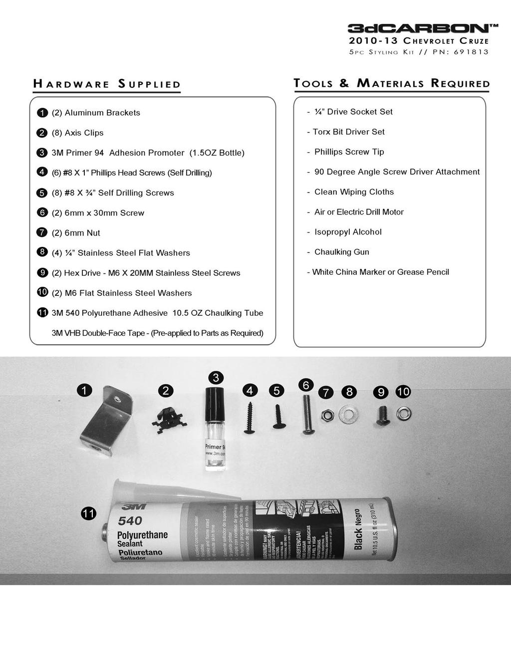
Double-check to ensure that all of the parts are included in your shipment. Please immediately contact 3dCarbon if you are missing any part.
|
|
|
- Annis Lucy Robertson
- 5 years ago
- Views:
Transcription

1
2 5 Pc. Kit Includes QTY 3D PN. DESCRIPTION CRUZE FRONT AIR DAM POLYURETHANE PRE-PRIMERED CRUZE SIDE SKIRT RH POLYURETHANE PRE-PRIMERED CRUZE SIDE SKIRT LH POLYURETHANE PRE-PRIMERED CRUZE REAR LOWER SKIRT POLYURETHANE PRE-PRIMERED CRUZE FLUSH DECK LID SPOILER POLYURETHANE PRE-PRIMERED Double-check to ensure that all of the parts are included in your shipment. Please immediately contact 3dCarbon if you are missing any part. Important Notice Vehicle Prepping Prior to Installation The procedure for installing the 3dCarbon Cruze Body kit involves three types of installation procedures Mechanical Screws - 3M VHB Tape and 3M 540 Polyurethane adhesive. It is critical that the paint surface of the vehicle be room temperature - no less than 70 deg F. The paint surface must be clean and free of any contamination: IE: dirt, road salt, moisture and wax. The procedure for cleaning the paint surface will include using wax and grease remove for any areas that have wax. Isopropyl alcohol on the paint surfaces where the VHB Tape and 3M 540 adhesive will come in contact. The wet out and curing time for the 3M Tape and 540 Adhesive is 24 Hours. Keep the vehicle dry and at room temperature for 24 hours after the installation to allow the wet out of the tape and curing of the 540 adhesive. For removal and reinstallation of any component of the body kit contact 3dCarbon for step-by-step technical support and reinstallation materials. The body kit components are pre-primered and ready for painting follow your paint suppliers recommendation for painting parts that have been primered. These parts are available pre painted in all factory colors from 3dCarbon CAUTION!!!! IF A HEATED SPRAY BOOTH IS USED FOR BAKING THE PRIMER OR PAINT. DO NOT BAKE OR CURE GREATHER THAN 120 F DEGREES FARENHEIT. THE PARTS CAN BE DISTORTED AND PERMANENTLY DAMAGED. SEE PREPPING & PAINTING INSTRUCTIONS FOR MORE INFO.
3

4 INSTALLATION STEPS // / FRONT AIR DAM Step 1) HARDWARE SUPPLIED 2 ALUMINUM BRACKETS RIGHT & LEFT WHEEL WELLS 2 M6 X 20MM STAINLESS STEEL SCREWS RIGHT & LEFT WHEEL WELLS 2 M6 FLAT STAINLESS STEEL WASHERS RIGHT & LEFT WHEEL WELLS 2 #8 X ¾ SELF DRILLING SCREWS UNDER FRONT CENTER AIR DAM 3M VHB DOUBLE-FACE TAPE PRE-APPLIED TO THE PARTS AS REQUIRED 3M 540 POLYURETHANE ADHESIVE CHAULKING TUBE Place the air dam on the front factory bumper and check the fit. The front center section should fit flush inside the opening on the bumper. Once the desired fit is achieved, use a white china marker, or grease pencil, to draw a reference line around the top of the part. Step 2) Step 3) Remove the part from the car. Using isopropyl alcohol on a clean wiping cloth, thoroughly wipe the paint surface where the 3M tape will attach. Be careful not to remove the grease pencil marks. Using the adhesion promoter supplied, apply the 3M 94 Adhesion Promoter to the paint surface where the tape will attach. Peel back a small piece of the red plastic protective liner from the tape, making a tail that can be pulled when the air dam is installed. IMAGE #1 Step 4) Using 3M 540 Polyurethane adhesive provided, apply a bead of the polyurethane in the channel located on the back of the air dam below the pre-applied 3M Tape (See Image #1). Do not apply the 540 Adhesive over the red plastic protective liner. Place the air dam on the car, positioning it using the grease pencil marks previously made as a reference. Starting with the center section, pull the red backing tail and press the air dam to the paint surface to ensure good adhesion of the double-face tape. IMAGE #2
 Locate and remove the original factory Torx drive screw from the bottom of the right and left front splash panel.")
 Locate the pre drilled hole on the bottom of the air dam using the (2) Hex Drive M6 X 20mm Stainless Steel screws and flat washers provided secure the air dam to the threaded insert")
5 Step 5) Step 6) Place one of the supplied Axis Clip s inside the right front wheel well, behind the pre-drilled hole, and secure with the #8 X 1 Phillips Head Screws. Repeat for left side. (See Image #2 on Previous Page) Locate and remove the original factory Torx drive screw from the bottom of the right and left front splash panel. Using the original screws removed secure the Aluminum brackets provided. (See Image #4) Locate the pre drilled hole on the bottom of the air dam using the (2) Hex Drive M6 X 20mm Stainless Steel screws and flat washers provided secure the air dam to the threaded insert on the aluminum bracket (See Image #5) IMAGE #4 IMAGE #5 Step 7) Using the #8 x ¾ self-tapping screws provided, secure the bottom center of the air dam to the factory splash panel.
 Check fit of the side skirts on the car.")
6 INSTALLATION STEPS S // SIDE SKIRTS HARDWARE SUPPLIED 2 ALUMINUM BRACKETS PRE-ATTRACTED TO THE SIDE SKIRTS ( R/L) 1 3M 540 POLYURETHANE ADHESIVE 4 AXIS CLIPS 3M VHB DOUBLE-FACE TAPE PRE-APPLIED TO THE PARTS AS REQUIRED 4 #8 X ¾ SELF DRILLING SCREWS 4 #8 X 1 PHILLIPS HEAD SCREWS Step 1) Check fit of the side skirts on the car. Step 2) Using isopropyl alcohol on a clean wiping cloth, thoroughly wipe the paint surface where the 3M tape will attach. Using the adhesion promoter supplied, apply the 3M 94 Adhesion Promoter to the paint surface where the tape will attach. Step 3) IMAGE #6 Peel back a small piece of the red plastic backing from the tape, making a tail that can be pulled when the side skirt is installed. (See Image #6) Step 4) Using 3M 540 Polyurethane adhesive provided, apply a bead of the polyurethane in the channel located on the back of the side skirt below the pre-applied 3M Tape. (See Image #6) Do not apply the 540 Adhesive over the red plastic protective liner. IMAGE #7 Step 5) Place one of the supplied Axis Clips inside the wheel well, behind the pre drilled hole, and secure with the #8 X 1 Phillips Head Screws. Repeat for the other hole. (See image #7)


 IMAGE #8 IMAGE #9")
7 Step 6) Apply a small amount of the 3M 540 Adhesive inside the aluminum bracket (See images #6, 8 and 9) Using a rubber mallet lightly tap the aluminum bracket onto the pinch weld (See image #10) IMAGE #8 IMAGE #9 IMAGE #10
 Step 2) Step 3) Check fit the rear lower wrap on the rear factory bumper, using the bodyline")
8 INSTALLATION STEPS // REAR LOWER HARDWARE SUPPLIED 2 AXIS CLIPS 4 #8 X 1 PHILLIPS HEAD SCREWS (MODIFIED TRUSS) 3M VHB DOUBLE-FACE TAPE PRE-APPLIED TO THE PART AS REQUIRED 2 ¼ x 20 x 1 HEX BOLT 2 ¼ X 20 X 1 HEX BOLT 2 ¼ X 20 X 1 STAINLESS STEEL WASHERS 1 3M 540 POLYURETHANE ADHESIVE CHAULKING TUBE Step 1) Step 2) Step 3) Check fit the rear lower wrap on the rear factory bumper, using the bodyline as a reference. Using a china marker or grease pencil, draw a line around the top edge of the part, so that you have a reference to line the part up during the final installation. Remove the part from the car. Using isopropyl alcohol on a clean wiping cloth, thoroughly wipe the paint surface where the 3M tape will attach. Be careful not to remove the grease pencil marks. Using the adhesion promoter supplied, apply the 3M 94 Adhesion Promoter to the paint surface where the tape will attach. Using 3M 540 Polyurethane adhesive provided, apply a bead of the polyurethane in the channel located on the back of the rear lower below the pre applied 3M Tape (See Image #11) Do not apply the 540 Adhesive over the red plastic protective liner. Peel back a small piece of the red plastic backing from the tape making a tail that can be pulled when the rear lower is installed (See Image #11) Place the rear lower back on the car, positioning it using the grease pencil marks as a reference. Starting with the either side right or left pull the red plastic tail and press the rear lower to the paint surface to insure adhesion of the double face tape. IMAGE #11 Step 4) Place one of the supplied Axis Clip s inside the wheel well behind the pre drilled hole and secure with the #8 X 1 Phillips Head Screws. Repeat for the other hole (See Image #12) IMAGE #12


9 Step 5) Using the 6mm x 30mm Screws and 6mm washers nuts, secure the rear lower to the bumper, as shown in image #13. Step 6) Locate the two pre-drilled holes in the rear lower. Using a screw gun, secure the rear lower to the bumper with the #8 x 1 screws, as shown in image #14 IMAGE #13 IMAGE #14

10 INSTALLATION STEPS S // FLUSH DECK LID SPOILER ER HARDWARE SUPPLIED 3M VHB DOUBLE FACE TAPE PRE-APPLIED TO PART 3M 540 POLYURETHANE ADHESIVE Step 1) Check fit spoiler on the deck lid. Align the spoiler right to left and front to rear. Check the measurement from the front leading edge of the deck lid to the front edge of the spoiler. The measurement should be 9 3/8. Using a china marker or grease pencil, draw a line along the edge of the part and make reference line that can be a couple hash marks on the glass and the spoiler, so that you have a reference to line the part up during the final installation. Step 2) Remove the part from the car. Using isopropyl alcohol on a clean shop towel clean the paint surface where the spoiler will attach. Be careful not to remove the grease pencil marks. Using the 3M 94 adhesion promoter supplied, apply the adhesion promoter to the paint surface where the tape will attach. IMAGE #15 Step 3) Peel back a small piece of the red plastic backing from the tape; making a tail that can be pulled when the rear spoiler is installed. (See Image #15) Using a chalking gun, apply the 3M 540 Adhesive to the channel on the bottom of the spoiler as shown in image # 16 Carefully place the rear spoiler back on the car, positioning it using the grease pencil marks as a reference. Press the spoiler firmly to the paint surface with a minimum of (15) Lbs. of force Starting with the either side right or left pull the red plastic tails and press the rear spoiler to the paint surface to insure adhesion of the double face tape. (See Image #16) IMAGE #16 3DCARBON BODY KITS CAR BODY KITS
QTY 3D PN. FCS PART NUMBER DESCRIPTION
 Rev.05-08 QTY 3D PN. FCS PART NUMBER DESCRIPTION 1 691224 A6ZEP-17B635-AAPLN MKZ FRONT AIR DAM 1 691202 A6ZEP-5410154-AAPLN MKZ SIDE SKIRT RH 1 691203 A6ZEP-5410155-AAPLN MKZ SIDE SKIRT LH 1 691225 A6ZEP-17E957-AAPLN
QTY 3D PN. FCS PART NUMBER DESCRIPTION
 QTY 3D PN. FCS PART NUMBER DESCRIPTION 1 691544 A8FOC-17B635-APL FOCUS FRONT AIR DAM 1 691549 A8FOC-17E957-APL FOCUS REAR LOWER 1 691548 A8FOC-10154-APL FOCUS RIGHT SIDE SKIRT 1 691547 A8FOC-10155-APL
QTY 3D PART NO. FORD SERVICE PN DESCRIPTION VAA6Z A FIESTA 5 DOOR (4) PC. KIT
 PC. KIT") Rev. 08-4 - 2010 QTY 3D PART NO. FORD SERVICE PN DESCRIPTION 1 691620 VAA6Z-5820049-A 2011- FIESTA 5 DOOR (4) PC. KIT HARDWARE SUPPLIED 12 #8 X ¾ SELF DRILLING SCREWS 220 / 18.5 3M VHB DOUBLE FACE TAPE
Rev. 08-4 - 2010 QTY 3D PART NO. FORD SERVICE PN DESCRIPTION 1 691620 VAA6Z-5820049-A 2011- FIESTA 5 DOOR (4) PC. KIT HARDWARE SUPPLIED 12 #8 X ¾ SELF DRILLING SCREWS 220 / 18.5 3M VHB DOUBLE FACE TAPE
QTY 3D PART NO. DESCRIPTION
 QTY 3D PART NO. DESCRIPTION 1 691032 V6 FRONT AIR DAM 1 691023 SIDE SKIRT RIGHT 1 691024 SIDE SKIRT LEFT 1 691566 V6 DUAL EXHAUST REAR LOWER SKIRT- 8 3M 94 3M ADHESION PROMOTER 24 #8 X ¾ SELF DRILLING
Expedition Front Bumper Instructions
 Expedition Front Bumper Instructions QTY 3D PN. FCS PART NUMBER DESCRIPTION 1 691256 A 8 E X D - 1 7 B 635-AAPLN FRONT BUMPER REPLACEMENT HARDWARE SUPPLIED 10 SELF TAPING SCREWS -10 for Front Bumper PLASTIC
Rev TOOLS & MATERIALS REQUIRED QTY 3D PART NO. DESCRIPTION
 Rev. 04-10 QTY 3D PART NO. DESCRIPTION 1 691609 FRONT BUMPER REPLACEMENT 1 691610 RIGHT SIDE SKIRT 1 691611 LEFT SIDE SKIRT 1 691612 REAR LOWER SKIRT 4 3M 94 3M ADHESION PROMOTER 16 #8 X ¾ SELF DRILLING
REV READ BEFORE INSTALLATION OF KIT:
 REV. 05-08 QTY 3D PN. FCS PART NUMBER DESCRIPTION 1 691509 A7EDG-7820049-AAPLN EDGE BODY KIT- V6 B PCS & EXH TIPS 1 691256 A 7 E D G - 7 8 20049-BAPLN EDGE BODY KIT- V6 8PCS & EXH TIPS W/HITCH 1 691501
INSTALLATION INSTRUCTIONS
 INSTALLATION INSTRUCTIONS Accessory Application Publications No. BII 24813 UNDER 2004 TSX Issue Date APRIL 2003 PARTS LIST Rear under spoiler 2 Short step bolts TOOLS AND SUPPLIES REQUIRED Phillips screwdriver
INSTALLATION INSTRUCTIONS
 INSTALLATION INSTRUCTIONS Accessory Application Publications No. BII 44686 2011 RL P/N 08R04-SJA-201 Issue Date DEC 2010 PARTS LIST INSTALLATION NOTE: Door visor (front left) These instructions show the
PART #137 & # DODGE DAKOTA HOODS
 Rev. 11/03 PART #137 & #138 97-04 DODGE DAKOTA HOODS Prefit Before Painting! STEP 1: Adjust hood until proper alignment with matching panels is achieved. STEP 2: Adjust primary latch until it fits into
INSTALLATION INSTRUCTIONS
 INSTALLATION INSTRUCTIONS Accessory Application Publications No. AII 27955 SIDE 2005 CIVIC SI Issue Date AUG 2004 PARTS LIST Left side under spoiler Right side under spoiler 6 Plates 8 Clips Template INSTALLATION
GENUINE REAR SPOILER
 GENUINE REAR SPOILER IMPORTANT POINTS IN PAINTING PART NAME: REAR SPOILER PART NUMBER: 0000-8Y-H50/GHK1 V4 920/G44B V4 920 VEHICLE: MAZDA6 1 PAINT AREAS SURFACE TREATMENT a : Paint same as body color b
INSTALLATION INSTRUCTIONS
 INSTALLATION INSTRUCTIONS Accessory Application Publications No. S P/N 08P21-STX-200 2008 MDX BII 37680 Issue Date AUG 2007 PARTS LIST Left bracket A Left front fender flare Left bracket B Left front bumper
INSTALLATION INSTRUCTIONS
 INSTALLATION INSTRUCTIONS Accessory Application Publications No. BII 41770 2010 RL P/N 08R04-SJA-201 Issue Date JUNE 2009 PARTS LIST INSTALLATION NOTE: Door visor (front left) These instructions show the
 INSTALLATION INSTRUCTIONS Accessory S P/N 08R04-SWA-100 Application 2010 CR-V Publications No. AII 42599 Issue Date AUG 2009 NOTE: Visors may not be legal in all states. Please check the laws of your state
INSTALLATION INSTRUCTIONS
 INSTALLATION INSTRUCTIONS Accessory Application 2011 CIVIC 4-DOOR Si Publications No. AII 44423 Issue Date AUG 2010 PARTS LIST Template Front under spoiler TOOLS AND SUPPLIES REQUIRED 4 Self-tapping screws
INSTALLATION INSTRUCTIONS
 INSTALLATION INSTRUCTIONS Accessory Application Publications No. FENDER FLARES P/N 08P21-S3V-200 2003 MDX BII 24553 Issue Date SEP 2002 PARTS LIST Right rear fender flare Left front fender flare Right
INSTALLATION INSTRUCTIONS
 INSTRUCTIONS Accessory Application Publications No. SIDE 2008 CIVIC 4-DOOR All 37741 Issue Date AUG 2007 PARTS LIST Left side under spoiler Right side under spoiler 2 Side lower brackets The side lower
INSTALLATION INSTRUCTIONS
 INSTALLATION INSTRUCTIONS Accessory Application Publications No. AII 24081 ACCORD 2-DOOR Issue Date SEP 2002 PARTS LIST INSTALLATION NOTE: Rear under spoiler Be careful not to damage the rear bumper and
REMOVAL AND INSTALLATION
 501-11-1 Glass, Frames and Mechanisms 501-11-1 REMOVAL AND INSTALLATION Windshield Glass Special Tool(s) Rotunda Pneumatic Knife with Offset Blade 107-R1511 or equivalent The Pumper 164-R2459 or equivalent
INSTALLATION INSTRUCTIONS
 INSTALLATION INSTRUCTIONS Accessory Application Publications No. BII 33322-36889 UNDER 2007 TL Issue Date MAY 2007 PARTS LIST Front under spoiler Left bracket (Marked L ) Right bracket (Marked R ) 8 Self-tapping
INSTALLATION INSTRUCTIONS
 INSTALLATION INSTRUCTIONS Accessory Application Publications No. UNDER 2007 CIVIC SI All 33529 Issue Date AUG 2006 PARTS LIST Rear under spoiler Clip Rubber washer 6 Flange bolts 6 Flange nuts TOOLS REQUIRED
GENUINE REAR SPOILER
 GENUINE REAR SPOILER INSTALLATION INSTRUCTIONS Thank you for purchasing a genuine Mazda accessory. Before removal and installation, be sure to thoroughly read these instructions. Please read the contents
 INSTALLATION INSTRUCTIONS Accessory Application Publications No. 2009 CIVIC HYBRID All 40191 Issue Date AUG 2008 PARTS LIST Rear under spoiler 2 Step bolts 4 Self-tapping screws TOOLS REQUIRED Phillips
SALEEN SPEEDLAB ROCKER PANELS KIT
 = SALEEN SPEEDLAB ROCKER PANELS KIT INSTALLATION MANUAL: 2005 to 2009 Mustang P/N: 10-8002-C12166C Saleen Performance, Inc. 1225 East Maple Rd. Troy, MI 48083 248-743-4800 www.saleen.com IF YOU ARE NOT
GENUINE PARTS INSTALLATION INSTRUCTIONS
 GENUINE PARTS INSTALLATION INSTRUCTIONS DESCRIPTION: APPLICATION: PART NUMBER: KIT-CARBON FIBER REAR SPOILER INFINITI Q50 T99J1 J5000 KIT CONTENTS: Item A B C D Qty. 1 4 1 1 Part Description Spoiler Assembly
FORD - F TOOLS CHECK LIST INSTALLATION MANUAL READ CAREFULLY BEFORE INSTALLATION FLOOR LINERS SET F ALL TYPE OF CABS
 FORD - F-250 2017 FLOOR LINERS SET F-250 2017 PART # : 1140NNTJFO23A12 LH ALL TYPE OF CABS RH NOT DESIGNED OR RECOMMENDED FOR MODELS EQUIPPED WITH VINYL FLOORING TOOLS ONLY SUPER CREW CAB PART # : 1140DNTUFO23A13
INSTALLATION INSTRUCTIONS
 INSTALLATION INSTRUCTIONS Accessory Application Publications No. SPOILER (LOW) 2011 CIVIC 4-DOOR All 44416 Issue Date AUG 2010 PARTS LIST Trunk spoiler Right trunk spring (marked red) Left trunk spring
Side Rocker Installation Instructions
 Side Rocker Installation Instructions Guidelines + Trial fit all parts prior to painting + Do not use the side rockers as an attachment point for tie downs + Every 3-6 months, make sure all fasteners are
Installation Instructions
 Option Code CSB Installation Instructions Accessory Deck Lid Spoiler 8W5-071-641 A- 3Q0 Fiber Mirror caps 8W0-072-530-A - 3Q0 (with side assist) Application 2017+ A4 Sedan Publication No. V 1.0 Installation
Roush Side Rocker Panel Splitters (10-13 All)
") Required tools: Jack stands (2) Floor jack (1 is required but 2 is preferred) Pliers Small Phillips screw driver Drill ¼ Drill bit T15 Torx bit (for some models of vehicle) Hacksaw (for some models of
Required tools: Jack stands (2) Floor jack (1 is required but 2 is preferred) Pliers Small Phillips screw driver Drill ¼ Drill bit T15 Torx bit (for some models of vehicle) Hacksaw (for some models of
INSTALLATION INSTRUCTIONS
 INSTALLATION INSTRUCTIONS Accessory SIDE S P/N 08F04-SZT-1T0 Application 2011 CR-Z Publications No. AII 43563 Issue Date AUG 2010 PARTS LIST Left side under spoiler Illustration of the Side Spoilers Installed
INSTALLATION INSTRUCTIONS
 INSTALLATION INSTRUCTIONS Accessory Application Publications No. SPOILER (LOW) CIVIC 4-DOOR All 30833 Issue Date SEP 2005 PARTS LIST Trunk spoiler Right trunk spring (marked red) Left trunk spring (marked
SUBARU FORESTER - SIDE STEP DIESEL VERSION INSTALLATION INSTRUCTIONS
 SUU FORESTER - SIDE STEP DIESEL VERSION INSTALLATION INSTRUCTIONS SS00 VEHICLE DESCRIPTION: PART NUMBER: SUU FORESTER SACC00 R 9 L 0 Care Instructions: Clean Side Steps with a mild detergent and water
INSTALLATION INSTRUCTIONS
 INSTALLATION INSTRUCTIONS Accessory Application Publications No. SPOILER (DECK LID) ACCORD 4-DOOR AII 24063 Issue Date AUG 2002 PARTS LIST Trunk spoiler Right trunk spring (marked green) Left trunk spring
DODGE RAM WITHOUT FENDER FLARES FRONT MUD GUARD INSTALLATION INSTRUCTIONS
 DODGE RAM WITHOUT FENDER FLARES FRONT MUD GUARD INSTALLATION INSTRUCTIONS PART NO: 5817 Please read instructions thoroughly before installation. Tools Required Short Phillips screwdriver Center punch Drill
INSTALLATION INSTRUCTIONS
 INSTALLATION INSTRUCTIONS Accessory SPOILER (LOW) P/N 08F10-TA0-100 Application 2009 ACCORD 4-DOOR Publications No. AII 40062 Issue Date JULY 2008 PARTS LIST Trunk spoiler Right trunk spring (marked red)
INSTALLATION INSTRUCTIONS
 INSTALLATION INSTRUCTIONS Accessory Application Publications No. SPOILER (LOW) ACCORD 4-DOOR AII 30276 Issue Date AUG 2005 PARTS LIST Trunk spoiler Right trunk spring (marked green) Left trunk spring (marked
INSTALLATION INSTRUCTIONS
 INSTRUCTIONS Accessory Application Publications No. 2011 CIVIC AII 44380 S 2-DOOR Issue Date AUG 2010 NOTE: The side under spoilers cannot be installed on a vehicle equipped with splash guards. PARTS LIST
 INSTRUCTIONS Accessory Application Publications No. 2006-2008 CIVIC AII 37696 SIDE 2-DOOR Issue Date AUG 2007 NOTE: Cannot be installed with splash guards. PARTS LIST Left side under spoiler Right side
JK8 Body Kit KIT CONTENTS 1 K
 JK8 Body Kit KIT CONTENTS A B C 1 K6861352 D E G F H 2 K6861352 I M N J K L O P Q R S 3 K6861352 T U V W X Y CALL OUT PART NUMBER DESCRIPTION QUANTITY A P5156021 HARDTOP 1 B P5155997 BULKHEAD 1 C 1PH98/9TZZAE
Aggressive Chin Spoiler CDC#
 Note: 2005-2009 Aggressive Chin Spoiler CDC# 110021 Read installation instructions before starting and test fit component before painting. Chin Spoiler is a molded Urethane part. To ensure the quality
INSTALLATION INSTRUCTIONS
 INSTALLATION INSTRUCTIONS Accessory P/N 08P48-TZ5-200 Application 2014 MDX Publications No. BII 48832 Issue Date MAY 2013 PARTS LIST Rear bumper applique Applicator INSTALLATION NOTE: Do not damage the
Wheel Arch Trim Set. Installation Manual. This section covers installation of the wheel arch trim set.
 Wheel Arch Trim Set FORESTER Wheel Arch Trim Set EN PART # E20SSG000 This section covers installation of the wheel arch trim set. Installation Manual Note: Before performing installation, be sure to read
INSTALLATION INSTRUCTIONS
 INSTALLATION INSTRUCTIONS Accessory Application Publications No. AII 24642 BODY SIDE CLADDING 2003 CR-V P/N 08P21-S9A-100 Issue Date OCT 2002 PARTS LIST Right rear bumper piece Right front fender piece
INSTALLATION INSTRUCTIONS
 INSTALLATION INSTRUCTIONS Accessory (WITH TEMPLATE) Application 2010 TL Publications No. BII 42533-44799 Issue Date AUG 2010 PARTS LIST Right rear under spoiler 4 Self-tapping screws 10 Seals Left rear
GENUINE PARTS INSTALLATION INSTRUCTIONS
 GENUINE PARTS INSTALLATION INSTRUCTIONS DESCRIPTION: APPLICATION: PART NUMBER: Hood Bug Deflector Pathfinder T99D5 9PJ0A KIT CONTENTS: Item Qty. A 2 Inner Clip A B 2 Outer Clip B C 2 Wing Clip C D 1 Hood
INSTALLATION INSTRUCTIONS
 INSTALLATION INSTRUCTIONS Accessory Application Publications No. All 30482 S 2006 PILOT Issue Date P/N 08F23-S9V-100A SEP 2005 PARTS LIST Left front trim piece Right front trim piece Left rear trim piece
PRELIMINARY INSTALLATION INSTRUCTIONS. PARTS LIST Left front trim piece
 INSTALLATION INSTRUCTIONS Accessory Application Publications No. All 30482 S 2006 PILOT Issue Date P/N 08F23-S9V-100A SEP 2005 PARTS LIST Left front trim piece Right front trim piece Left rear trim piece
Included in Hardware Kit. Rear Corners 2-Door. Jeep JK Trail Armor. Set Part #14009 Rev STEP 1 - PRIOR TO INSTALLATION
 Jeep JK Trail Armor Set Part #14009 Rev-2 02-23-11 A) B) C) STEP 1 - PRIOR TO INSTALLATION Bushwacker only approves installing the trail armor according to these written instructions with the hardware
INSTALLATION INSTRUCTIONS PARTS LIST. SUPPLIES REQUIRED Isopropyl alcohol Shop towel Masking tape Tape measure. Door visor (front left) INSTALLATION
 INSTALLATION") INSTALLATION INSTRUCTIONS Accessory Application Publications No. All 13348 2013 RIDGELINE P/N 08R04-SJC-100 Issue Date SEP 2012 PARTS LIST Door visor (front left) SUPPLIES REQUIRED Isopropyl alcohol Shop
INSTALLATION INSTRUCTIONS Accessory Application Publications No. All 13348 2013 RIDGELINE P/N 08R04-SJC-100 Issue Date SEP 2012 PARTS LIST Door visor (front left) SUPPLIES REQUIRED Isopropyl alcohol Shop
INSTALLATION INSTRUCTIONS
 INSTALLATION INSTRUCTIONS Accessory Application Publication No. After 13 TRX420 All MII 15067 KIT (except 14 TRX420FA/FPA) Issue Date P/N 08T71-HR3-A20 After 13 TRX500 All (except 14 TRX500FA/FPA) September
Volkswagen New Beetle Body - Exterior 53 Body - Rear (Page GR-53)
") 53 Body - Rear (Page GR-53) Body, rear Rear end, assembly overview Rear fender, assembly overview Transparent foil protection for rear fenders Body, rear (Page 53-1) Rear end, assembly overview Note: The
53 Body - Rear (Page GR-53) Body, rear Rear end, assembly overview Rear fender, assembly overview Transparent foil protection for rear fenders Body, rear (Page 53-1) Rear end, assembly overview Note: The
DRAWING NO WI APPROVAL ISSUER: ENGINEERING: PRODUCTION/MATERIAL: QA APPROVAL: REV 2 DATE BAS BAS WRC
 Installation Instruction Tr/IPSNET Door Sensor DRAWING NO WI 005-184-501 APPROVAL ISSUER: ENGINEERING: PRODUCTION/MATERIAL: QA APPROVAL: REV 2 DATE BAS BAS WRC WRC REVISION HISTORY LTR DESCRIPTION DATE
INSTALLATION INSTRUCTIONS
 Accessory Application Publication No. INSTALLATION INSTRUCTIONS HEATED GRIPS ATTACHMENT KIT P/N 08T70-MJL-D30 2014-2015 NC700X/XD Honda Dealer: Please give a copy of these instructions to your customer.
Installation: 2008 Scion XD
 ONLINE For a free PDF download of the 2008 Scion XD glass removal and replacement instructions, visit GlassMagazine.com. Vehicle information A5 Vehicle type: Four-door hatchback NAGS numbers*: Windshield
Rear Spoiler Installation Instructions
 Rear Spoiler Installation Instructions Guidelines For complete instructions in color, please go to our website at www.ivsauto.com If your Camaro did not come with an OEM spoiler, IVS kit # 9006-1013-01
INSTALLATION INSTRUCTIONS
 Accessory Application Publications No. INSTALLATION INSTRUCTIONS SIDE S 2013 TSX BII 13496 Issue Date SEP 2012 PARTS LIST 4 Screws Left side under spoiler Right side under spoiler 2 Clamps TOOLS AND SUPPLIES
INSTALLATION INSTRUCTIONS
 INSTALLATION INSTRUCTIONS Accessory REAR SPOILER Application 2011 CR-Z MUGEN Publications No. AII 45919 Issue Date APRIL 2011 PARTS LIST Right wing bracket Rear wing Left wing bracket Right wing base Right
POLY TIP-DOWN WINDSHIELD KIT
 POLY TIP-DOWN WINDSHIELD KIT P/N 2883261 APPLICATION Verify accessory fitment at Polaris.com. BEFORE YOU BEGIN Read these instructions and check to be sure all parts and tools are accounted for. Please
INSTALLATION INSTRUCTIONS
 INSTALLATION INSTRUCTIONS Accessory S P/N 08R04-TP6-100 Application 2010 ACCORD CROSSTOUR Publications No. AII 41956 Issue Date NOV 2009 PARTS LIST Left front door visor Illustration of the Door Visors
INSTALLATION INSTRUCTIONS
 INSTALLATION INSTRUCTIONS Accessory LED BRAKE LIGHT P/N 08U76-MKC-A00 Application GL1800/D/DA GL1800B/BD Honda Dealer: Please give a copy of these instructions to your customer. Publication No. MII 16426
INSTALLATION INSTRUCTIONS
 INSTALLATION INSTRUCTIONS Accessory Application Publications No. 2007 CIVIC SI AII 33461 SIDE Issue Date AUG 2006 PARTS LIST Left side under spoiler PARTS LIST Left side sticker (Sold separately) Right
INSTALLATION INSTRUCTIONS
 INSTALLATION INSTRUCTIONS Accessory Application Publications No. 2006 CIVIC AII 30895 SIDE 2-DOOR Issue Date SEP 2005 PARTS LIST PARTS LIST Left side sticker Left side under spoiler Right side sticker
INSTALLATION INSTRUCTIONS
 INSTALLATION INSTRUCTIONS Accessory Application 2012 CIVIC 4-DOOR Publications No. AII 45625-46263 Issue Date MAY 2011 PARTS LIST Trunk spoiler Left trunk spring (marked yellow) Template 4 Clip grommets
INSTALLATION INSTRUCTIONS
 INSTALLATION INSTRUCTIONS Accessory SIDE UNDER S Application 2013 CIVIC 2-DOOR Publications No. AII 13069 Issue Date NOV 2012 PARTS LIST 4 Flare nuts Left spoiler 2 Washer-nuts Right spoiler 2 Screws 2
INSTALLATION INSTRUCTIONS
 INSTALLATION INSTRUCTIONS Accessory Application Publications No. AII 25852 PILOT Issue Date AUG 2003 PARTS LIST INSTALLATION NOTE: Door visor (Front left) These instructions show the left door visors being
3 PIECE HARD TONNEAU COVER INSTALLATION INSTRUCTIONS
 3 PIECE HARD TONNEAU COVER INSTALLATION INSTRUCTIONS VEHICLE DESCRIPTION: NISSAN NAVARA D0 DUAL CAB 3 Pce Tonneau Cover with OEM Sports Bar 3 Pce Tonneau Cover with EGR Sports Bar PLACE THESE INSTRUCTIONS
2011 Cadillac CTS Coupe EGX Exhaust Tip & Rear Valance Mesh Accent Kit Part #: Complete E
 BILLET GRILLS IMPORTANT: PLEASE KEEP THIS INSTRUCTION MANUAL FOR FUTURE REFERENCE! 2011 Cadillac CTS Coupe EGX Exhaust Tip & Rear Valance Mesh Accent Kit Part #: Complete 5122-1900-11E TOOLS REQUIRED Automotive
INSTALLATION INSTRUCTIONS
 Accessory Application Publication No. INSTALLATION INSTRUCTIONS HEATED GRIP ATTACHMENT P/N 08T70-MJE-D00 CBR650F/FA MII 14960 Issue Date April 2014 PARTS LIST HEATED GRIP Sold separately (1) (2) (4) (2)
INSTALLATION INSTRUCTIONS
 INSTALLATION INSTRUCTIONS Accessory Application Publications No. All 28593 2006 RIDGELINE P/N 08F23-SJC-100 Issue Date FEB 2005 PARTS LIST Center front bumper trim (Not used if the vehicle is equipped
(6) Universal Mounting Brackets (NOTE: same bracket used for left or right side installation) Driver/left Running Board (example only)
 Universal Mounting Brackets (NOTE: same bracket used for left or right side installation) Driver/left Running Board (example only)") PARTS LIST: Qty Description Qty Description 6 Universal Left/Right Mounting Brackets 12 6-1.0mm x 20mm T-Bolts 12 8-1.25mm Clip-On Nuts 12 6mm x 22mm OD x 2mm Flat Washers 12 8-1.25mm x 25mm Hex Bolt 12
PARTS LIST: Qty Description Qty Description 6 Universal Left/Right Mounting Brackets 12 6-1.0mm x 20mm T-Bolts 12 8-1.25mm Clip-On Nuts 12 6mm x 22mm OD x 2mm Flat Washers 12 8-1.25mm x 25mm Hex Bolt 12
INSTALLATION INSTRUCTIONS
 INSTALLATION INSTRUCTIONS Accessory Application Publications No. AII 44415 2011 CIVIC 4-DOOR Issue Date AUG 2010 PARTS LIST Trunk spoiler 2 Cap nuts 2 Screws Left trunk spring (marked yellow) Right trunk
Ground Effects, P/N: (V6), (V8)
, (V8)") , P/N: 92248596 (V6), 92248560 (V8) 3. Open trunk and remove 3 scrivets per side. Retain. Remove LH and RH tail lamp access cover. Retain. Refer to Figure 1. NOTE: Installation is made easier with the
, P/N: 92248596 (V6), 92248560 (V8) 3. Open trunk and remove 3 scrivets per side. Retain. Remove LH and RH tail lamp access cover. Retain. Refer to Figure 1. NOTE: Installation is made easier with the
OVERVIEW: This bulletin involves removing and installing the deck lid spoiler.
 NUMBER: 23-041-05 GROUP: Body DATE: September 9, 2005 This bulletin is supplied as technical information only and is not an authorization for repair. No part of this publication may be reproduced, stored
GENUINE PARTS INSTALLATION INSTRUCTIONS
 GENUINE PARTS INSTALLATION INSTRUCTIONS 1. 2. 3. 4. DESCRIPTION: Front Protector Kit APPLICATION: G Sedan Sports PART NUMBER: K6010-1NH** (XX Designates color) KIT CONTENTS: Item Qty. Description Part
Vehicle and all installation material temperatures must be within the following range before and during installation: 60 F [15 C] and 100 F [43 C].
![Vehicle and all installation material temperatures must be within the following range before and during installation: 60 F [15 C] and 100 F [43 C].](/thumbs/90/101815149.jpg "Vehicle and all installation material temperatures must be within the following range before and during installation: 60 F [15 C] and 100 F [43 C].") INSTALLATION INSTRUCTIONS DESCRIPTION: BODY SIDE MOLDING KIT, DEALER Vehicle and all installation material temperatures must be within the following range before and during installation: 60 F [15 C] and
INSTALLATION INSTRUCTIONS DESCRIPTION: BODY SIDE MOLDING KIT, DEALER Vehicle and all installation material temperatures must be within the following range before and during installation: 60 F [15 C] and
INSTALLATION INSTRUCTIONS
 Accessory Application Publication No. INSTALLATION INSTRUCTIONS ATTACHMENT P/N 08T70-MGZ-D80 CB500X/XA MII 14565 Issue Date May 2013 PARTS LIST KIT Sold separately (1) (2) (4) (2) (1) (3) BOOT (1 piece.)
3PC TONNEAU COVER WITH SPORTS BAR INSTALLATION INSTRUCTIONS
 3PC TONNEAU COVER WITH SPORTS BAR INSTALLATION INSTRUCTIONS TC00d / Vehicle Description: NISSAN NAVARA D0 DUAL CAB 3-PIECE TONNEAU COVER PARTS LIST NO. PART NAME QTY. NO. PART NAME QTY. NO. PART NAME QTY.
INSTALLATION INSTRUCTIONS
 INSTALLATION INSTRUCTIONS Accessory S P/N 08R04-TK6-100A Application 2012 FIT Publications No. AII 45990 Issue Date AUG 2011 PARTS LIST Door Visors cannot be installed on a vehicle equipped with the accessory
VOLKSWAGEN AMAROK 3 PIECE HARD TONNEAU COVER INSTALLATION INSTRUCTIONS
 VOLKSWAGEN AMAROK 3 PIECE HARD TONNEAU COVER INSTALLATION INSTRUCTIONS Care Instructions: Clean Tonneau Cover with a mild detergent and water solution. Do not use abrasive cleaners or solvents. Place these
SECTION Glass, Frames and Mechanisms
 501-11-i Glass, Frames and Mechanisms 501-11-i SECTION 501-11 Glass, Frames and Mechanisms CONTENTS PAGE Windshield Glass... 501-11-2 501-11-2 Glass, Frames and Mechanisms 501-11-2 Windshield Glass Special
LANCER EVOLUTION (2008 ) MUD FLAP MZ531356EX (Black with aluminum plate) MZ531357EX (Black standard) INSTALLATION AND HANDLING INSTRUCTIONS
 MUD FLAP MZ531356EX (Black with aluminum plate) MZ531357EX (Black standard) INSTALLATION AND HANDLING INSTRUCTIONS") LANCER EVOLUTION (2008 ) MUD FLAP MZ531356EX (Black with aluminum plate) MZ531357EX (Black standard) INSTALLATION AND HANDLING INSTRUCTIONS Black with aluminum plate -MZ531356EX Black standard -MZ531357EX
LANCER EVOLUTION (2008 ) MUD FLAP MZ531356EX (Black with aluminum plate) MZ531357EX (Black standard) INSTALLATION AND HANDLING INSTRUCTIONS Black with aluminum plate -MZ531356EX Black standard -MZ531357EX
(2012 Production Onwards) INTEGRATED SIDE STEP INSTALLATION INSTRUCTION. 60 Minutes
 INTEGRATED SIDE STEP INSTALLATION INSTRUCTION. 60 Minutes") NISSAN DUALIS (2012 Production Onwards) INTEGRATED SIDE STEP INSTALLATION INSTRUCTION Accessory Part No. STEP0004 60 Minutes Approx Product Weight: 15kg/33 lb IMPORTANT - PLEASE READ INSTRUCTIONS BEFORE
NISSAN DUALIS (2012 Production Onwards) INTEGRATED SIDE STEP INSTALLATION INSTRUCTION Accessory Part No. STEP0004 60 Minutes Approx Product Weight: 15kg/33 lb IMPORTANT - PLEASE READ INSTRUCTIONS BEFORE
INSTALLATION INSTRUCTIONS
 INSTALLATION INSTRUCTIONS Accessory WELL P/N 08P21-STX-200A Application 2012 MDX Publications No. BII 46618 Issue Date OCT 2011 PARTS LIST Left front fender trim Bracket A-L Left front bumper trim Bracket
2015+ Mustang Rear Valance Installation Instructions P/N: (R F953) (R F953BS)
 (R F953BS)") 2015+ Mustang Rear Valance Installation Instructions P/N: 421894 (R1315-17F953) 421919 (R1315-17F953BS) 39555 Schoolcraft Rd, Plymouth MI, 48170 800.59.ROUSH 2015+ Mustang Rear Valance Kit Installation
2015+ Mustang Rear Valance Installation Instructions P/N: 421894 (R1315-17F953) 421919 (R1315-17F953BS) 39555 Schoolcraft Rd, Plymouth MI, 48170 800.59.ROUSH 2015+ Mustang Rear Valance Kit Installation
INSTALLATION INSTRUCTIONS
 INSTALLATION INSTRUCTIONS PARTS LIST Accessory Application Publications No. MII 13038 GL1800 P/N 08E75-MCA-100K Issue Date November 2009 Honda Dealer: Please give a copy of these instructions to your customer.
ASX / OUTLANDER SPORT SHIFT KNOB MZ525507EX INSTALLATION AND HANDLING INSTRUCTIONS
 ASX / OUTLANDER SPORT SHIFT KNOB MZ55507EX INSTALLATION AND HANDLING INSTRUCTIONS Thank you for purchasing the Mitsubishi Genuine Accessory. To install and use the product correctly with proper knowledge
INSTALLATION INSTRUCTIONS
 Accessory Application Publication No. INSTALLATION INSTRUCTIONS S ATTACHMENT KIT P/N 08T70-MJW-D90 After 15 CB500X/XA Honda Dealer: Please give a copy of these instructions to your customer. MII 15802
INSTALLATION INSTRUCTIONS
 INSTALLATION INSTRUCTIONS Accessory Application Publications No. Bll 37371 SPOILER 2008 TL Issue Date JUN 2007 PARTS LIST Trunk spoiler Left trunk spring (marked yellow) Template A TOOLS AND SUPPLIES REQUIRED
POLY TIP-DOWN WINDSHIELD KIT
 POLY TIP-DOWN WINDSHIELD KIT P/N 2881919 APPLICATION Verify accessory fitment at Polaris.com. BEFORE YOU BEGIN Read these instructions and check to be sure all parts and tools are accounted for. Please
INSTALLATION INSTRUCTIONS
 INSTALLATION INSTRUCTIONS Accessory Application Publications No. SPOILER (LOW) 2005 ACCORD 4-DOOR AII 27503 Issue Date AUG 2004 PARTS LIST Trunk spoiler Right trunk spring (marked green) Left trunk spring
INSTALLATION INSTRUCTIONS
 INSTALLATION INSTRUCTIONS Accessory Application Publications No. 3RD ROW P/N 08R12-SHJ-100 2006 ODYSSEY AII 30563-31117 Issue Date OCT 2005 PARTS LIST Left side rear sunshade Driver s Side 1. Remove the
GENUINE ILLUMINATED SCUFF PLATE
 GENUINE ILLUMINATED SCUFF PLATE INSTALLATION AND USER S INSTRUCTIONS Thank you for purchasing a Genuine Mazda Accessory. Before removal and installation, please thoroughly read these instructions. For
 INSTALLATION INSTRUCTIONS www.collegehillshonda.com Accessory P/N 08P21-SZA-100 Application 2009 PILOT Publications No. AII 39455 Issue Date MAY 2008 NOTE: The fender trim cannot be installed on vehicles
INSTALLATION INSTRUCTIONS
 INSTALLATION INSTRUCTIONS Accessory Application Publications No. Bll 30250 UNDER SPOILER 2006 RSX Issue Date JULY 2005 PARTS LIST Rear under spoiler 5 Stepped bolts 2 Bolts 7 Flange nuts, 6 mm 3 Square
INSTALLATION INSTRUCTIONS
 INSTALLATION INSTRUCTIONS Accessory P/N 08P48-T3L-100 Application 2013 ACCORD 2-DOOR Publications No. AII 13018 Issue Date OCT 2012 PARTS LIST Rear bumper applique Illustration of the Rear Bumper Applique
INSTALLATION INSTRUCTIONS
 INSTALLATION INSTRUCTIONS Accessory DECK LID SPOILER Application 2014 RLX Publications No. BII 13399 Issue Date JAN 2013 PARTS LIST Trunk spoiler Left trunk spring (marked yellow) Right trunk spring (marked
Mini Cooper Mini Cooper. Vehicle Type: Two-Door Hatchback. Windshield. AutoGlass Field Guide 53
 Vehicle Type: Two-Door Hatchback NAGS number:* FW02305GTY (Heat) (Rain Sensor) or FW02304GTY. Original-equipment-manufacturer part numbers are 51311505850 (Heat) (Rain Sensor), or 51311505875. FD21652-53
INSTALLATION INSTRUCTIONS
 Accessory Application Publication No. INSTALLATION INSTRUCTIONS CHROME TRUNK RACK P/N 08L70-MKC-A00 GL1800/D/DA GL1800B/BD Honda Dealer: Please give a copy of these instructions to your customer. MII 16426