Model Number Nomenclature
|
|
|
- Austin Singleton
- 6 years ago
- Views:
Transcription

1


2
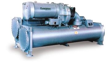
3 Model Number Nomenclature DJ S 52 Description -High Efficiency Hermetic Centrifugal Liquid Chiller Motor Voltage Code 52-(380V-3PH-50HZ) 55-(6300V-3PH-50HZ) Cooler Size 30, 31, 32 35, 36, 37 40, 41, 42 45, 46, 47 50, 51, 52 55, 56, 57 60, 61, 62 65, 66, 67 70, 71, 72 75, 76, 77 80, 81, 82 85, 86, 87 Condenser Size 30, 31, 32 35, 36, 37 40, 41, 42 45, 46, 47 50, 51, 52 55, 56, 57 60, 61, 62 65, 66, 67 70, 71, 72 75, 76, 77 80, 81, 82 85, 86, 87 Motor Efficiency Code S JStandard Efficiency H JHigh Efficiency Motor Code CD DC EH CE DD EJ CL DE EK CM DF EL CN DG EM CP DH EN CQ DJ EP Compressor Code First Digit Indicates Compressor Frame Size Note:carrier is dedicated to continuous product development.components list will vary to meet different demands 1
4 Features Designed specifically for chlorine-free HFC-134a refrigerant (the environmentally preferred HFC-134a refrigerant with zero-ozone-depletion potential) Chlorine-free HFC-134a Chlorine-free HFC-134a refrigerant protects the ozone layer. The positive pressure design reduces the chiller size by up to 35% compared to low-pressure designs. The smaller size minimizes the need for valuable mechanical room floor space. In addition, positive-pressure designs eliminate the need for the costly low-pressure containment devices. Key chiller components design uses advanced jet engine technology. Reliability Several safety measures greatly improve operating reliability of chiller Aerodynamically contoured impellers - Impellers that use high back sweep main blades with low-rent and are smaller and lighter than profile intermediate splitter blades are aerodynamically contoured to improve compressor full-load and part-load operating efficiency. Efficiency Key chiller components design ensures high efficiency of chiller with advanced jet engine technology Convenience LCD in English simplifies the interaction between chiller and user Variable inlet guide vanes - The guide vanes are connected with air-water piping, reducing installation craft-quality cable and controlled by a precise electronic actuator. The vanes regulate inlet flow to provide high efficiency through a wide operating range. High performance tubing - Tubing with internally and externally enhanced fins improves chiller performance by reducing the overall resistance to heat transfer. The newly designed heat exchanger reduces refrigerant charge, cutting expenses. The AccuMeter TM system regulates refrigerant flow according to load conditions, providing a liquid seal at all operating conditions and eliminating unintentional hot gas bypass. The optimized piping design reduces refrigerant flow pressure loss, ensuring chiller efficiency. 2
5 Single-stage design - This increases product reliability by eliminating the additional moving parts associated with multiple stage chillers. Refrigerant-cooled oil cooler-refrigerant cooling eliminates field water piping, reducing installation expense. Cooler and condenser are designed and manufactured in accordance with the Standard of Pressure Vessel of China. The unit isolation valves make the heat exchangers into a liquid containers and the pump out system is also provided to output refrigerant, which provides ease of maintenance. Mix-match capability - The chillers provide a complete line of compressors, motors and heat exchangers, ensuring the best combination of chiller components regardless of tonnage, lift, and efficiency specifications. Water boxes are equipped with standard flanges, which facilitate the field installation and protect temperature sensor. International Chiller Visual Control (ICVC) -a large English LCD (liquid crystal display) features 4 menu-specific soft keys. The default display offers all in one glance review of key chiller operation data, simplifying the interaction between chiller and user. Direct digital Product Integrated Control (PIC II)- Automated controls test can be executed prior to start-up to verify that the entire control system is functioning properly. Carrier's PIC II integrates directly with the Carrier Comfort Network (CCN) via dataport module, providing a system solution to controls applications. 3
6 Selection Table Model CLS 336CMS 347CNS 356CPS 386CQS 385CQS 447DFS 447DGS 457DHS 467DHS 467DJS DJS 545EHS 555EKS ELS 585EMS 595ENS 595EPS 505EPS Nominal Cooling kw 1,055 1,231 1,406 1,582 1,758 1,934 2,110 2,285 2,461 2,637 2,813 3,059 3,164 3,516 3,868 4,218 4,571 4,922 5,274 Chiller Capacity Tons Full load ikw/kw Performance Power Supply 380V-3Ph-50Hz Power Motor Rated Current Locked Rotor Current kw A A Flow Rate I/s 50.4 Cooler Pressure Drop kpa 84.1 Nozzle Size mm Flow Rate I/s 60.8 Condenser Drop Pressure kpa 67 Nozzle Size mm Length mm 4172 Dimensions Width mm 1707 Height mm DN DN200 DN250 DN300 DN350 DN300 DN DN200 DN250 DN300 DN350 DN300 DN Operating kg Weight Rigging R134a Charge kg kg Notes: 1. The above selection is made based on the In/Out temperature of CW being 12/7 o C, and that of CDW being 32/37 o C; the fouling factor of cooling water side being m2 o C/kW, and that of chilled water side being m2 o C/kW. 2. Carrier will select specific models using computer on different requests for tonnage, lift, and efficiency. For details, please contact local agencies. 3. The above selection is made based on the voltage being 380V. For details, please contact local agencies. 4
7 Elecrical Date Motor Motor Electrical 380V Electrical Data Motor Motor Electrical 380V Electrical Data Size Characteristics Max Ikw(kw) Amps(A) Size Characteristics Max Ikw(kw) Amps(A) CDS CES CLS CMS CNS CPS CQS DCS DDS DES DFS DGS DHS DJS Motor Size Motor Electrical Characteristics 380V Electrical Data Max Ikw(kw) Amps(A) Motor Size Motor Electrical Characteristics 380V Electrical Data Max Ikw(kw) Amps(A) EHS EJS EKS ELS EMS ENS EPS EHH EJH EKH ELH EMH ENH EPH Notes: 1. Legend: -Rated Load Amps, -Locked Rotor Y Amps, -Locked Rotor Delta Amps. 2. For other details, please contact local agencies. 5
8 Chiller Dimensions Tube Removal Clearance for Either End Motor Service Clearance 1219mm Recommended Overhead Service Clearance 915mm(Frame 3-4 Compressor) 1524mm(Frame 5 Compressor) C A Min 362 mm B Service Clearance Min 610 mm Heat Exchanger Size A-Length mm(2 passes) B-Width mm C-Height mm D-Tube Removal Space for Either End mm 30 ~ ~ ~ ~ ~ ~ ~ ~ ~ ~ ~ ~ Notes: 1.A-length includes flanges with both cooler and condenser having two passes and nozzles being at the same end (compressor end for standard units) 2. The above dimensions are based on the waterside pressure being 1.0Mpa. A-length will vary while the waterside pressure increases. Starter Dimensions (380V-3Ph-50Hz ) Starter Type Rated Current(A) Width(mm) Y- Y- Y ~ ~ Notes: The wiring of starter enters and exits from the bottom. Depth(mm) Height(mm)
9 Nozzle Dimensions Frame 3 Frame 4-8 Drive End (Type A) For C of Cooler Waterbox: 5 in and 6 out For R of condenser Water box:7 in and 8 out Compressor End (Type B) For D of Cooler Waterbox: 3 in and 4 out For S of condenser Water box:1 in and 2 out Heat Exchanger Size 30 ~ 32 Frame 3 35 ~ 37 A B C D E F G H ØP (mm) DN200 Heat Exchanger Size A B C D ØE ØF H I 40 ~ 42 Frame 4 Frame 5 Frame 6 Frame 7 Frame 8 45 ~ ~ ~ ~ ~ ~ ~ ~ ~ DN200 DN200 DN250 DN300 DN350 DN200 DN250 DN250 DN300 DN Notes: 1. Nozzles of standard units are at the compressor end (Type B). Type A is also available on request. 2. The above dimensions are based on the waterside pressure being 1.0Mpa. Dimensions will vary while the waterside pressure increases. 7
10 Typical Piping and Wiring 1 Air Switch 2 Freestanding Compressor Motor Starter 3 Compressor Motor Terminal Box 4 Oil Pump Controller 5 6 Vents 7 Pressure Gauges 8 Chilled Water Pump 9 Cooling Water Pump 10 Control Panel Chilled Water Pump Starter 11 Cooling Water Pump Starter 12 Cooling Tower Fan Starter 13 Air Switch 14 Oil Pump Switch Line 1 # 4 # 5 # 6 # 7 # 8 # 9 # 10 # Purpose Main power to Starter: To Cooling Tower Fan Starter: To Cooling Tower Water Pump Starter: To Chilled Water Pump Starter: To Oil Heater Contactor: To Oil Pump Contactor: To Lube System Power Panel: To Motor: Specification 380V AC: 3 phases, 1 neutral, and 1grounding Or 6300V AC: 3 phases, 1 grounding (medium voltage) 2 control lines (optional) 2 control lines (optional) 2 control lines (optional) 115V AC: 2 power lines, 1 grounding 380V AC power line, 3 phases 5A 8 control shielding lines, 600V, 80oC, grounding in starter 380V AC: 6 leads (Minimum ampacity per conductor = x ), 2 grounding Or 6300V AC: 3 leads, 1 grounding (medium voltage) Piping and Wiring Requirements: 1. The installer must get all pipes and wires in place and mark the ends. 2. Filter must be installed in cooling water and chilled water pipes. 3. Thermometer (0-50 o C) and pressure gauge (0~1Mpa or 2MPa) must be installed at inlet and outlet of the pipes. 4. The installer must install the relief valve vent to outdoors with a steel pipe.(outer diameter 42mm, thickness 4mm) 5. It is suggested that an oxygen content monitor be installed in the machine room for safety, which will give an alarm when the oxygen content is less than 19.5%. 8
11 Types of Base Isolation Location Of Isolator Condenser Center Accessory Soleplate Cooler Center Standard Isolation Support Plate See Note 1 THK(25)H.R.S. Soleplate Tube Sheet Jacking Screw See Note#2 Level Base Line See Note#3 Support Plate Elastomeric Pad Jacking Screw(s) Soleplate View X-X Leveling Pad Leveling Pad(s) Simplified Isolation Tube Sheet Support Plate Elastomeric Pad Notes: 1. Accessory soleplate package includes 4 soleplates, 16 jacking screws, and 16 leveling pads. 2. Jacking Screws should be removed after the grout has set 3. Thickness of grout will vary, depending on the View Y-Y amount necessary to level chiller. Heat Exchanger Size A B C D E F G H J Frame 3 30~32 35~ Frame 4 40~42 45~ Frame 5 50~52 55~ Frame 6 60~62 65~ Frame 7 70~72 75~ Frame 8 80~82 85~
12 Option Specifications Waterside Pressure of condenser: the standard pressure is 1.0Mpa. 2.0Mpa is also available if necessary. Waterside Pressure of cooler: the standard pressure is 1.0Mpa. 2.0Mpa is also available if necessary. Spring Isolator: the standard isolator is made of elastomeric rubber. Spring Isolator is also available for further isolation if necessary. Noise Reduction Covering for Vent-pipe: this helps reduce the noise by 1~2dB (A) (For details, please contact local agencies.) Dimension Selection for Selected Model Centrifugal Chillers can be configured according to customers' requirements. Dimensions of chiller, piping and base correspond to the heat exchanger and can be identified in the table listed in the catalog. Take as an example CQS, of which the size of cooler and condenser is 41 and 42 respectively: See Chiller Dimension Table on Page 6, the Heat Exchanger 40~42 Line for length, width, height of the chiller as follows: A-Length B-Width C-Height D-Tube Removal Space Heat Exchanger Size mm mm mm mm 40 ~ See Nozzle Dimensions Table on Page 7, the Heat Exchanger 40~42 Line for dimensions of main nozzles and flanges as follows: Heat Exchanger Size A B C D ØE ØF H I 40 ~ DN200 DN See Base Dimensions Table on Page 9, the Heat Exchanger 40~42 Line for base dimensions as follows: Heat Exchanger Size 40 ~ 42 A 3931 B 1829 C 92 D 387 E 229 F 540 G 464 H 254 J
.")
13 Microprocessor Controls Microprocessor controls provide the safety, interlock, and indications necessary to operate the chiller in a safe and efficient manner. In addition, the program logic ensures proper starting, stopping, and recycling of the chiller and provides a communication link to the Carrier Comfort Network (CCN). The microprocessor control on each Carrier centrifugal system is factory mounted, wired, and tested to ensure machine protection and efficient capacity control. Control system Safety cutouts Display LCD with Language Pre-programmed for Chinese Component Test and Diagnostic Check Programmable Recycle Allows Chiller to Recycle at Optimum Loads for Decreased Operating Costs Menu-Driven Keypad Interface for Status Display, Set Point Control, and System Configuration CCN Compatible Primary and Secondary Status Message Individual Start/Stop Schedules for Local and CCN Operation Modules Recall of Up to 25 Alarm/Alert Messages with Diagnostic Help Two Chiller Lead/Lag with Third Chiller Standby is Standard in the PIC II Software Optional Soft Stop Unloading Closes Guide Vanes to Unload the Motor to the Configured Amperage Level Prior to Stopping Bearing Oil High Temperature* Motor High Temperature*+ Refrigerant (Condenser) High Pressure*+ Refrigerant (Cooler) Low Pressure*+ Lube Oil Low Pressure Compressor (Refrigerant) Discharge Temperature* Under Voltage** Over Voltage** Oil Pump Motor Overload Cooler and Condenser Water Flow Motor Overload+ Motor Acceleration Time Intermittent Power Loss Compressor Starter Faults Compressor Surge Protection* Low Level Ground Fault Low Level-phase to phase and phase to ground Chiller Operation Status Message Power-On Pre-Start Diagnostic Check Compressor Motor Amps Pre-Alarm Alert++ Alarm Contact for Remote Alarm Safety Shutdown Messages Elapsed Time (Hours of Operation) Chiller Input kw Capacity Control Leaving Chilled Water Control Entering Chilled Water Control Soft Loading Control by Temperature or Load Ramping Guide Vane Actuator Module Hot Gas Bypass Valve Power (Demand) Limiter Interlocks Manual/Automatic Remote Start Starting/Stopping Sequence Pre-lube/Post-Lube Pre-Flow/Post-Flow Compressor Starter Run Interlock Pre-Start Check of Safeties and Alerts Low Chilled Water (Load) Recycle Monitor/Number Compressor Starts and Run Hours Manual Reset of Safeties Notes: These can be configured by users to provide alert indication at user-defined limit. Override Protection: Causes compressor to first unload and then, if necessary, shut down. Will not require manual reset or cause an alarm if auto-restart after power failure is enabled. By display code only. 11
14 !" Field Wiring Typical Field Wiring With Free-Standing Starter (380V-3Ph-50HZ) 12
15 !!"!"! 13
16 Field Wiring Typical Field Wiring With Free-Standing Starter (Medium Voltage) 14
17 15
18 Field Wiring Specifications General 1. Starters shall be designed and manufactured in accordance with Carrier Engineering Requirement Z All field-supplied conductors, devices, and the field-installation wiring, termination of conductors and devices, must be in compliance with all applicable codes and job specifications. 3. The routing of field-installed conduit and conductors and the location of field-installed devices must not interfere with equipment access or the reading, adjusting, or servicing of any component. 4. Equipment installation and all starting and control devices, must comply with details in equipment submittal drawings and literature. 5. Contacts and switches are shown in the position they would with the circuit deenergized and the chiller shut down. 6. WARNING - Do not use aluminum conductors. 7. Installer is responsible for any damage caused by improper wiring between starter and machine. Power Wiring to Starter 1. Circuit breaker is to be used to disconnect power to starter. 2. Unit-mounted starter power conductor rating must meet minimum nameplate voltage and compressor motor. 3. Lug adapters may be required if installation conditions dictate that conductors be sized beyond the minimum ampacity required. 4. Flexible conduit should be used for the last few feet of the power conductor to start enclosure to provide unit vibration isolation. 5. Compressor motor and controls must be grounded by using equipment-grounding lugs provided inside unit mounted starter enclosure. 6. Unit-mounted starters with "Rated Load Amps" () greater than 700 (Benshaw) or 935 (Cutler Hammer) require the assembly and the installation of a "Top Hat" (located inside enclosure) to provide the required wire bending space for incoming power leads. Control Wiring 1. Field supplied control conductors should be at least 1 mm 2 or larger. 2. Optional ice build start/terminate device contacts, optional remote start/stop device contacts and optional spare safety device contacts, must have 24 VAC rating. MAX current is 60 MA, nominal current is 10 MA. Switches with gold plated bifurcated contacts are recommended. 3. Remove jumper wire between J2-1 and J2-2 before connecting auxiliary safeties between these terminals. 4. ISM contact outputs can control cooler and condenser pump and tower fan motor contactor coil loads (VA) rated 5 Amps at 115 VAC up to 3 Amps at 277 VAC. Do not use starter control transformer as the power source for contactor coil loads. 5. Do not route control wiring carrying 30 v or less within a conduit which has wires carrying 50 v or higher or along side wires carrying 50 v or higher. 6. Control wiring between free-standing starter and power panel must be separate shielded cables with minimum rating of 600 v, 80 C ground shield at starter. 7. If optional oil pump circuit breaker is not supplied within the starter enclosure as shown, it must be located within sight of the chiller with wiring routed to suit. 16
19 Power Wiring Between Free-Standing Starter and Compressor Motor 1. Low voltage (600 v or less) compressor motors have (6) 5/8 terminal studs (lead connectors not supplied by Carrier). Either 3 or 6 conductors must be run between compressor motor and starter, depending on the type of motor starter employed. If only 3 leads are utilized, jumper motor terminals as follows : 1 to 6, 2 to 4, and 3 to 5. Center to center distance between terminals is 8mm.Compressor motor starter must have nameplate stamped as to conform with Carrier Engineering Requirement Z Medium voltage [over 600 volts] compressor motors have (3) terminals. Connections are 9/16-threaded stud. Compressor motor starter must have nameplate stamped as to conform with Carrier Engineering requirement "Z-415." 3. Power conductor rating must meet compressor motor. When (3) conductors are used: Minimum ampacity per conductor = 1.25 x compressor When (6) conductors are used: Minimum ampacity per conductor = x compressor 4. When more than one conduit is used to run conductors from starter to compressor motor terminal box, three leads from each phase (conductor) must be in each conduit to prevent excessive heating (e.g., conductors to motor terminals 1, 2, & 3 in one conduit, and those to 4, 5, & 6 in another). 5. Compressor motor power conductors may enter terminal box through top, bottom or right side using holes cut by contractor to suit conduit. Flexible conduit should be used for the last few feet to the terminal box for unit vibration isolation. 6. Compressor motor frame should be grounded in accordance with the National Electrical Code (NFPA-70) and applicable codes. Means for grounding compressor motor is a #4 AWG-500 MCM pressure connector, supplied and located in the lower left side corner of the compressor motor terminal box. 7. Do not allow motor terminals to support weight of wire cables. Use cable supports and strain relieves as required. 8. Use backup wrench when tightening lead connectors to motor terminal studs. Torque to 45 lb-ft max. 9. Motor terminals and wire connectors must be insulated with insulation putties and tapes attached to chillers to prevent moisture condensing and electrical arc. 17

20
30GX AIR-COOLED LIQUID CHILLER
 30GX-4SB 30GX080-265 AIR-COOLED LIQUID CHILLER PERFORMANCE DATA FIELD WIRING DIAGRAM 1997 Carrier Corporation Syracuse, New York 13221 Form 30GX-4SB Supersedes 30GX-3SB Printed in U.S.A. 12-97 Catalog
30GX AIR-COOLED LIQUID CHILLER
 30GX-5SB 30GX080-265 AIR-COOLED LIQUID CHILLER PERFORMANCE DATA FIELD WIRING DIAGRAM 1998 Carrier Corporation Syracuse, New York 13221 Form 30GX-5SB Supersedes 30GX-4SB Printed in U.S.A. 5-98 Catalog No.
 CENTRIFUGAL CHILLER TECHNICAL DATA SHEET Job Name: Mt Healthy Junior Senior HS Date: 6/25/2009 Version: 06.12 Submitted By: Mary Wilking Unit Description: McQuay Model Number: WSC100MBJ72R/E4212-CE-3**/C3612-BLYY-2*****/R134-BAABM
SECTION MOTORS AND VARIABLE FREQUENCY DRIVES
 PART 1 GENERAL 1.1 RELATED DOCUMENTS A. Related Sections: 1. Section 15050 - Basic Mechanical Requirements. 2. Section 15051 - Motors. 3. Section 15185 - Hydronic Pumps. 4. Section 15625 - Centrifugal
Liebert CSU3000 DISCONTINUED PRODUCT. CSI Mainframe Cooling Systems. CT(Three Module) Model 20, 30 & 37 ton Mainframe Chiller
 Model 20, 30 & 37 ton Mainframe Chiller") DISCONTINUED PRODUCT CSI 15621 - Mainframe Cooling Systems 1.1 SUMMARY Liebert CSU3000 CT(Three Module) Model 20, 30 & 37 ton Mainframe Chiller GUIDE SPECIFICATIONS 1.0 GENERAL These specifications describe
DISCONTINUED PRODUCT CSI 15621 - Mainframe Cooling Systems 1.1 SUMMARY Liebert CSU3000 CT(Three Module) Model 20, 30 & 37 ton Mainframe Chiller GUIDE SPECIFICATIONS 1.0 GENERAL These specifications describe
SECTION MOTOR CONTROL
 SECTION 26 24 19 MOTOR CONTROL PART 1 - GENERAL 1.1 SECTION INCLUDES A. Manual motor starters B. Magnetic motor starters C. Combination magnetic motor starters D. Solid-state reduced voltage motor starters
CWP-CO / CWP-RC / CWP-HP 02 to 35
 Water Cooled Water Chillers Cooling Only, Condenserless and Heat Pump Versions - / - / - 02 to 35 8 to 136 9 to 164 Technical Brochure TM -N.4GB Date : March 2006 Supersedes : TM -N.3GB/05.04 Technical
University of Houston Master Construction Specifications Insert Project Name SECTION ELECTRONIC VARIABLE SPEED DRIVES PART 1 - GENERAL
 SECTION 23 04 10 ELECTRONIC VARIABLE SPEED DRIVES PART 1 - GENERAL 1.1 RELATED DOCUMENTS: A. The Conditions of the Contract and applicable requirements of Division 1, "General Requirements", and Section
Product Catalog. NQ Series. Portable and Remote Air-Cooled Condenser Chillers 4 to 43 Tons
 Product Catalog NQ Series Portable and Remote Air-Cooled Condenser Chillers 4 to 43 Tons Page Intentionally Blank Contents Standard Features...1 Available Options...3 Oversized Pumps... 3 High Flow Unit
FIELD CONNECTIONS MODEL YK CHILLERS (STYLE F AND G) WITH VARIABLE SPEED DRIVE
 WITH VARIABLE SPEED DRIVE") Supersedes: 160.54-PW6 (513) Form 160.54-PW6 (816) WIRING DIAGRAM CONTRACTOR ORDER NO. YORK CONTRACT NO. YORK ORDER NO. FIELD CONNECTIONS MODEL YK CHILLERS (STYLE F AND G) WITH VARIABLE SPEED DRIVE PURCHASER
Supersedes: 160.54-PW6 (513) Form 160.54-PW6 (816) WIRING DIAGRAM CONTRACTOR ORDER NO. YORK CONTRACT NO. YORK ORDER NO. FIELD CONNECTIONS MODEL YK CHILLERS (STYLE F AND G) WITH VARIABLE SPEED DRIVE PURCHASER
UD SERIES COMPRESSORS
 UD SERIES COMPRESSORS INDUSTRIAL AIR COMPRESSOR 40-400 HP UPDRAFT MODELS Electric Motor - 460/575/3/60 standard (208/230/3/60 optional on most models) Motor Starter - 460 volt, full voltage magnetic starter
RCD Air Cooled Condensing Unit (50/60 Hz)
") Environment friendly Easy to access components More efficient air cooled condenser coils Easy to install and maintain The Saudi Factory for Air Conditioning Units RCD Air Cooled Condensing Unit (50/60
Environment friendly Easy to access components More efficient air cooled condenser coils Easy to install and maintain The Saudi Factory for Air Conditioning Units RCD Air Cooled Condensing Unit (50/60
Chiller. AQL/AQH 40 to 75. Air Cooled Water Chillers Cooling Only and Heat Pump Engineering Data Manual to 77.2 kw to 75.
 Chiller AQL/ to 75 Air Cooled Water Chillers Only and Heat Pump Engineering Data Manual.0 to 75.8 kw 39.9 to 77.2 kw Outstanding Strength Points R410A Refrigerant. New simpler refrigerant circuit layout.
6. Document tasks performed during visit and report any observations to the appropriate
 Chiller Annual Maintenance RFP Attachment B Services Required Tasking: Vibration Analysis 1. All work shall be performed in accordance with safety policies 2. Check with appropriate customer representative
PRODUCT DRAWING WIRING DIAGRAM FIELD CONNECTIONS MILLENNIUM MODEL YT CHILLERS (STYLE J) WITH ELECTRO-MECHANICAL STARTER JOB DATA:
 WITH ELECTRO-MECHANICAL STARTER JOB DATA:") Supersedes: 160.55-PW4 (1199) FORM 160.55-PW4 (600) PRODUCT DRAWING YORK INTERNATIONAL CORPORATION P.O. Box 1592, YORK, PA 17405 CONTRACTOR ORDER NO. YORK CONTRACT NO. YORK ORDER NO. WIRING DIAGRAM FIELD
Supersedes: 160.55-PW4 (1199) FORM 160.55-PW4 (600) PRODUCT DRAWING YORK INTERNATIONAL CORPORATION P.O. Box 1592, YORK, PA 17405 CONTRACTOR ORDER NO. YORK CONTRACT NO. YORK ORDER NO. WIRING DIAGRAM FIELD
CWP. Cooling Only Version (CO) Condenserless Version (RC) Heat Pump Version (HP) Models 02 to 35. Engineering Data Manual. Water Cooled Water Chillers
 Condenserless Version (RC) Heat Pump Version (HP) Models 02 to 35. Engineering Data Manual. Water Cooled Water Chillers") Engineering Data Manual Water Cooled Water Chillers Cooling Only Version () Condenserless Version () Heat Pump Version () Models 02 to 35 8 to 136 9 to 164 N IRWELL GROUP MPNY Specifications General The
Engineering Data Manual Water Cooled Water Chillers Cooling Only Version () Condenserless Version () Heat Pump Version () Models 02 to 35 8 to 136 9 to 164 N IRWELL GROUP MPNY Specifications General The
OTEC Transfer switch open transition
 Specification sheet OTEC Transfer switch open transition 40 1200 amp Description OTEC transfer switches are designed for operation and switching of electrical loads between primary power and Standby generator
Co m f o r t Li n k N A V I G A T O R F F
 TIME EWT LWT SETP Co m f o r t Li n k N A V I G A T O R 1 2.58 5 4. 6 F 4 4. 1 F 4 4. 0 F M O D E Alarm Status Run Status Service Test Temperatures Pressures Setpoints Inputs Outputs Configuration Time
Air-Cooled Liquid Chiller with integrated hydraulic module
 Air-Cooled Liquid Chiller with integrated hydraulic module Cooling only: CGAN 200-250 - 300-400 - 450-490 - 500-600 - 700-800 - 900-925 Reversible: CXAN 200-250 - 300-400 - 450-490 - 500-600 - 700-800
Air Cooled Water Chillers. CLS 182 to to 150 kw. Technical Brochure TM CLS-W.3GB Date : October 2004 Supersedes : TM CLS-W.2GB/07.
 Air Cooled Water Chillers CLS 182 to 602 41 to 150 kw Technical Brochure TM CLS-W.3GB Date : October 2004 Supersedes : TM CLS-W.2GB/07.04 R Specifications General characteristics The CLS air cooled water
Transfer switch OTEC and OTECSE open transition
 Specification sheet OTEC and OTECSE open transition 125-600 Amp Description OTEC transfer es are designed for operation and ing of electrical loads between primary power and standby generator sets. They
Air Cooled Condensing Units - Technical Catalog. Featuring CopelandTM Compressors 404A and 507 Refrigerants
 N SERIES Air Cooled Condensing Units - Technical Catalog Featuring CopelandTM s 404A and 507 Refrigerants 4492 Hunt St - Pryor, OK 74361-918.825.7222 - Fax 800.264.5329 - www.century-refrigeration.com
Product Catalog TSE Series Scroll Central Chillers
 Product Catalog TSE Series Scroll Central Chillers Contents Features...1 Available Options...3 Hot Gas Bypass Valve... 3 Rotary Non-Fused Disconnect Switch... 3 Integral Reservoir and Pumping System...
SECTION DOMESTIC-WATER PACKAGED BOOSTER PUMPS
 SECTION 221123.13 - DOMESTIC-WATER PACKAGED BOOSTER PUMPS PART 1 - GENERAL 1.1 RELATED DOCUMENTS A. Drawings and general provisions of the Contract, including General and Supplementary Conditions and Division
Defender Mini Online Emergency Central Lighting Inverter (CLI) Technical Specifications
 Technical Specifications") Defender Mini Online Emergency Central Lighting Inverter (CLI) Technical Specifications PART 1 GENERAL 1.1 SUMMARY A. The Defender Mini CLI specification describes a single phase, online, solid state Lighting
Defender Mini Online Emergency Central Lighting Inverter (CLI) Technical Specifications PART 1 GENERAL 1.1 SUMMARY A. The Defender Mini CLI specification describes a single phase, online, solid state Lighting
VLH 504 to Air-to-Water Reverse Cycle Heat Pumps. 126 to 294 kw. 133 to 307 kw
 Air-to-Water Reverse Cycle Heat Pumps VLH 504 to 1204 126 to 294 kw 133 to 307 kw Technical Brochure TM VLH-N.3GB Date : June 2005 Supersedes : TM VLH-N.2GB/07.04 Specifications Advantages Range extension
LSE kw. Outdoor packaged unit. Air/water chillers and heat pumps LSE PLUS
 Air/water chillers and heat pumps LSE Outdoor packaged unit LSE 60-00 kw Multi-scroll solutions for reliability and high efficiency at partial loads Scroll compressor PLUS R-0A R-0A refrigerant Cooling
Fortress 1 Outdoor Emergency Central Lighting Inverter (CLI) Technical Specifications
 Technical Specifications") Fortress 1 Outdoor Emergency Central Lighting Inverter (CLI) Technical Specifications PART 1 GENERAL 1.1 SUMMARY A. This specification describes a single phase, on-line, double conversion, solid state
Fortress 1 Outdoor Emergency Central Lighting Inverter (CLI) Technical Specifications PART 1 GENERAL 1.1 SUMMARY A. This specification describes a single phase, on-line, double conversion, solid state
Cobra 3 Stand-By Emergency Central Lighting Inverter (CLI) Technical Specifications
 Technical Specifications") Cobra 3 Stand-By Emergency Central Lighting Inverter (CLI) Technical Specifications PART 1 GENERAL 1.1 SUMMARY A. This specification describes a stand-by, three-phase, solid state Lighting Inverter System
Cobra 3 Stand-By Emergency Central Lighting Inverter (CLI) Technical Specifications PART 1 GENERAL 1.1 SUMMARY A. This specification describes a stand-by, three-phase, solid state Lighting Inverter System
Sample Specifications 2110_KA.DOC KOBELCO KNW SERIES 1 OF 10 AIR-COOLED, OIL FREE AIR COMPRESSOR Frame 0, 1, HP
 KOBELCO KNW SERIES 1 OF 10 1. SPECIFICATIONS SCOPE 1.1 This specification covers the requirement for supply of a packaged oil-free rotary screw air compressor, Kobelco KNW Series model. 1.2 Any and all
MECHANICAL AND ELECTRICAL COORDINATION SECTION MECHANICAL AND ELECTRICAL COORDINATION PART 1 - GENERAL
 13686.00 MECHANICAL AND ELECTRICAL COORDINATION 230002-1 SECTION 230002 MECHANICAL AND ELECTRICAL COORDINATION 1.1 WORK INCLUDED PART 1 - GENERAL A. Work Included in This Section: Materials, equipment,
Product Catalog TSE Series Scroll Central Chillers
 Product Catalog TSE Series Scroll Central Chillers Contents Features...1 Hot Gas Bypass Valve... 2 Rotary Non-Fused Disconnect Switch... 2 Integral Reservoir and Pumping System... 3 Remote Condenser Coil
Sample Specifications 2111_A00.doc 01/18/06 KOBELCO KNWA00 SERIES 1 of 8 AIR-COOLED, OIL FREE AIR COMPRESSOR Frame HP
 KOBELCO KNWA00 SERIES 1 of 8 1. SPECIFICATION SCOPE 1.1 This specification covers the requirement for supply of a packaged oil-free rotary screw air compressor, Kobelco KNW Series model. 1.2 Any and all
ROGERS MACHINERY COMPANY, INC
 KOBELCO KNW SERIES Sample Specifications AIR-COOLED, OIL-FREE AIR COMPRESSOR Frame 0, 1, 2 50 500 HP ROGERS 2110_KA.doc Effective: 03-24-17 Supersedes: 04-06-15 Page 1 of 9 1. SPECIFICATIONS SCOPE 1.1
AIR COOLED CHILLERS WATER COOLED CHILLERS
 AIR COOLED CHILLERS WATER COOLED CHILLERS STANDARD UNIT SPECIFICATIONS OF COMMERCIAL AIR COOLED CHILLERS General Description & Assembly Air Cooled Chillers are commercial packaged systems complete with
CAS. Product Specifications. COMMERCIAL SPLIT SYSTEMS CONDENSING UNITS R 410A, 6 to 20 TONS BUILT TO LAST, EASY TO INSTALL AND SERVICE
 COMMERCIAL SPLIT SYSTEMS CONDENSING UNITS R 410A, 6 to 20 TONS BUILT TO LAST, EASY TO INSTALL AND SERVICE Single stage cooling capacity control on all 0 241 models Two stage cooling capacity control on
YCUJ Millennium TM AIR COOLED CONDENSING UNIT
 YCUJ Millennium TM AIR COOLED CONDENSING UNIT REFRIGERANT R407C COOLING CAPACITIES 348 kw to 760 kw The YCUJ range of Condensing Units are designed for direct expansion cooling and are usually used in
PERFORMANCE DATA TYPICAL FIELD WIRING CERTIFIED DIMENSION PRINTS CERTIFIED ROOF CURB DIMENSION PRINTS
 50FP-1SB 50FP034, 038, 044, 048, 054, 064, 074 SINGLE-PACKAGE COOLING UNITS CONSTANT/VARIABLE VOLUME PRODUCT INTEGRATED CONTROLS CARRIER COMFORT NETWORK COMPATIBLE FACTORY-INSTALLED OPTIONAL ELECTRIC HEAT
abc CPD7948/075 Rotors, rotor shafts and rotor casings are coated with an anti-corrosive and anti wear coating to prolong element life and efficiency.
 CPD7948/075 Specification Oil-Free, Air Cooled, Rotary Screw Compressors - Dryclon Range Models D75, D90, D110, D132, D150 (50Hz) D55, D75, D90, D110, D150 (60Hz) COMPRESSOR PACKAGE An enclosed two stage
Advantage-D. Operating Instructions and Maintenance Manual. Central Vacuum Systems (Expandable/Modular Models) (Ver.
 (Ver.") Advantage-D Series 3 Central Vacuum Systems (Expandable/Modular Models) (Ver. 8/05) Operating Instructions and Maintenance Manual DESCRIPTION The Becker Advantage-D and Advantage-L central vacuum systems
Advantage-D Series 3 Central Vacuum Systems (Expandable/Modular Models) (Ver. 8/05) Operating Instructions and Maintenance Manual DESCRIPTION The Becker Advantage-D and Advantage-L central vacuum systems
Air-Cooled Screw Compressor Chiller
 Installation, Operation and Maintenance Manual IOMM ALS Group: Chiller Part Number: 070774401 Date: February 1998 Supersedes: IM 548-3 Air-Cooled Screw Compressor Chiller ALS 070A through 425A 60 Hertz
Power Lynx 3 Uninterruptible Power System (UPS) Technical Specifications
 Technical Specifications") Power Lynx 3 Uninterruptible Power System (UPS) Technical Specifications PART 1 GENERAL 1.1 SUMMARY A. This specification describes a three phase, on-line, double conversion, solid state Uninterruptible
Power Lynx 3 Uninterruptible Power System (UPS) Technical Specifications PART 1 GENERAL 1.1 SUMMARY A. This specification describes a three phase, on-line, double conversion, solid state Uninterruptible
Single-Phase Step Voltage Regulators
 Voltage Regulators Catalog Data CA225001EN Supersedes March 2017 COOPER POWER SERIES Single-Phase Step Voltage Regulators Contents GENERAL....2 STANDARD FEATURES....4 OPTIONAL ACCESSORIES...4 ARRESTERS....4
DENVER PUBLIC SCHOOLS DESIGN AND CONSTRUCTION STANDARDS This Standard is for guidance only. SECTION MOTORS, STARTERS & DRIVES
 PART 0 DESIGN STANDARDS 0.01 GENERAL DESIGN GUIDELINES A. Coordinate starter needs for mechanical equipment prior to 50% CD and confirm again for 100% CD submittal. B. Coordinate temperature controls requirements
SCROLL - AIR COOLED PACKAGED & SPLIT SYSTEM ICE CHILLERS
 SCROLL - AIR COOLED PACKAGED & SPLIT SYSTEM ICE CHILLERS 1 to 40 Nominal Tons Rev-01 TABLE OF CONTENTS Page: Description 3 4 5 6 7 8 9 10 11 12 13 14 15 16 17 18 19 20 Product Nomenclature Air Cooled Chiller
ROGERS MACHINERY COMPANY, INC
 KOBELCO KNW SERIES Sample Specifications ROGERS MACHINERY COMPANY, INC WATER-COOLED, OIL-FREE AIR COMPRESSOR Frame 00 20-50 HP 2110_00.doc Effective: 03/24/17 Supersedes: 10-11-13 Page 1 of 8 1. SPECIFICATION
FIELD CONNECTIONS FOR YK CHILLER (STYLE G) OPTIVIEW CONTROL CENTER WITH REMOTE MEDIUM VOLTAGE SSS
 OPTIVIEW CONTROL CENTER WITH REMOTE MEDIUM VOLTAGE SSS") Supersedes: 160.75-PW2 (508) Form 160.75-PW2 (311) FIELD CONNECTIONS FOR YK CHILLER (STYLE G) OPTIVIEW CONTROL CENTER WITH REMOTE MEDIUM VOLTAGE SSS WIRING DIAGRAM CONTRACTOR ORDER NO. YORK CONTRACT NO.
Supersedes: 160.75-PW2 (508) Form 160.75-PW2 (311) FIELD CONNECTIONS FOR YK CHILLER (STYLE G) OPTIVIEW CONTROL CENTER WITH REMOTE MEDIUM VOLTAGE SSS WIRING DIAGRAM CONTRACTOR ORDER NO. YORK CONTRACT NO.
 Standard Features 200-600V, 50/60Hz input power supply Built-in run rated (AC1) By-pass contactor up to 820 A * Rated 450% current Conformal coated circuit board Voltage ramp or current limit start modes
SLH 1202 to Air-to-Water Reverse Cycle Heat Pumps. With Screw Compressors. 261 to 775 kw. 287 to 853 kw
 Air-to-Water Reverse Cycle Heat Pumps SLH 1202 to 3804 With Screw Compressors 261 to 775 kw 287 to 853 kw Technical Brochure TM SLH-A.2GB Date : November 2004 Supersedes : TM SLH-A.1GB/05.04 Design Features
Fortress 3 Harsh. Harsh Environment. Emergency Central Lighting Inverter (CLI) Technical Specifications
 Technical Specifications") Fortress 3 Harsh Emergency Central Lighting Inverter (CLI) Technical Specifications PART 1 GENERAL 1.1 SUMMARY A. This specification describes a three phase, on-line, double conversion, solid state Lighting
Fortress 3 Harsh Emergency Central Lighting Inverter (CLI) Technical Specifications PART 1 GENERAL 1.1 SUMMARY A. This specification describes a three phase, on-line, double conversion, solid state Lighting
PH120. Rooftop Packaged. R410a Refrigerant PERFORMANCE DATA OUTDOOR COIL ENTERING TEMPERATURE 0 C
 PH120 R410a Refrigerant Rooftop Packaged INDOOR COIL ENTERING AIR TEMP 0 c DB WB 21 23 25 27 29 31 PERFORMANCE DATA OUTDOOR COIL ENTERING TEMPERATURE 0 C 30 35 40 45 Cap Cap Cap Cap 17 115.3 70.7 11.5
2.1 Warnings & Agency Approvals Electrical Connections - Specifications Standard Wiring Configurations...2 4
 CHAPTER ELECTRICAL 2 INSTALLATION Contents of this Chapter... 2.1 Warnings & Agency Approvals..................2 2 2.1.1 Isolation..............................................2 2 2.1.2 Electrical Power
RVS-DN Digital Reduced Voltage Motor Starter
 RVS-DN Digital Reduced Voltage Motor Starter Specification Guide Specification Guide Contents 1.0 Introduction 2.0 Specifications 2.1 Standard Performance Features 2.2 Standard Protection Features 2.3
PROJECT MANUAL GUIDE SPECIFICATIONS FOR: PFANNENBERG SERIES EB COMPACT PACKAGED CHILLERS PART 1 GENERAL
 PROJECT MANUAL GUIDE SPECIFICATIONS FOR: PFANNENBERG SERIES EB COMPACT PACKAGED CHILLERS PART 1 GENERAL 1.1 SUMMARY A. Packaged Chillers offer a self-contained means of producing cooling liquid primarily
Centrifugal Chiller. PF/PFH Size: 063. Replacement Parts List No Revision V 05/2012
 Replacement Parts List No. 057113900 Revision V 05/2012 Centrifugal Chiller PF/PFH Size: 063 To find your Daikin McQuay parts distributor, call 1-800-377-2787 or visit www.daikinmcquay.com Contents Parts
High efficiency industrial type semi-hermetic twin helical screw compressor.
 YCAS AIR COOLED SCREW CHILLER R407C REFRIGERANT COOLING CAPACITIES 260 kw to 1194 kw The YCAS range of chillers are designed for water or water-glycol cooling. Models are available with 2, 3 and 4 refrigerant
Transfer switch OTEC open or delayed transition
 Transfer switch OTEC open or delayed transition 40-1000 Amp Description OTEC transfer switches are designed for operation and switching of electrical loads between primary power and standby generator sets.
Application Engineering
 Application Engineering February, 2009 Copeland Digital Compressor Controller Introduction The Digital Compressor Controller is the electronics interface between the Copeland Scroll Digital Compressor
The Enclosed Altistart 22 Soft Start/Soft Stop Motor Controller
 The Enclosed Altistart 22 Soft Start/Soft Stop Motor Controller A pre-engineered solution with an integrated circuit breaker disconnect and an Altistart 22 soft start in a stand-alone enclosure Make the
Wiring Diagrams DIAGRAM INDEX
 30HK040-060;30HL050,060;30HW018-040 Reciprocating Liquid Chillers with ComfortLink Controls 50/60 Hz Wiring Diagrams DIAGRAM INDEX UNIT 30 VOLTAGE DIAGRAM TYPE FIGURE LABEL DIAGRAM All Component Arrangement
SeasonPak Packaged Air-Cooled Water Chiller
 Installation Manual IM 676 Group: Chiller Part Number: 594920Y Date: July 1996 Supersedes: None SeasonPak Packaged Air-Cooled Water Chiller Models ALR 032E Through 185E 1996 McQuay International Table
MODELS YCRL0064, 0074, 0084, 0096, 0118, 0126, 0156, 0177, 0198, 0200, 0230, 0260, 0300, 0345, 0385, 0445, 0530 and YCRL0610 STYLE "A"
 WATER-COOLED LIQUID CHILLERS HERMETIC SCROLL RENEWAL PARTS Supercedes: 150.7-RP1 (709) Form: 150.7-RP1 (810) MODELS YCRL0064, 0074, 0084, 0096, 0118, 016, 0156, 0177, 0198, 000, 030, 060, 0300, 0345, 0385,
CHILLER MODEL NO. YS SOLID STATE STARTER, MODEL NO. SSS, L B OPTIONAL FACTORY INSTALLED DISCONNECT SWITCH AMPS OR
 WIRING DIAGRAMS CONTRACTOR ORDER NO. JCI CONTRACT NO. JCI ORDER NO. Supersedes: 160.80-PW4 (1099) Form: 160.80-PW4 (215) FIELD CONNECTIONS ROTARY SCREW CHILLER WITH GRAPHIC CONTROL CENTER AND YORK MOD
PERFORMANCE DATA TYPICAL FIELD WIRING CERTIFIED DIMENSION PRINT CERTIFIED ROOF CURB DIMENSION PRINTS
 50FN-1SB 50FNX,FNY078,088,104 SINGLE-PACKAGE COOLING UNITS CONSTANT/VARIABLE AIR VOLUME PRODUCT INTEGRATED CONTROLS CARRIER COMFORT NETWORK COMPATIBLE WITH INTEGRAL ECONOMIZER AND HIGH-CAPACITY MODULATING
CTi Automation - Phone: Fax: Web:
 CTi Automation - Phone: 800.894.0412 - Fax: 208.368.0415 - Web: www.ctiautomation.net - Email: info@ctiautomation.net The control & protection you expect in an innovative soft starter design... Flexibility
WARREN COUNTY, N.Y. M/E REFERENCE A. Submit manufacturer's product data on all motors and adjustable speed drives.
 SECTION 230513 - MOTORS AND ADJUSTABLE SPEED DRIVES PART 1 - GENERAL 1.1 DESCRIPTION A. Provide labor, materials, equipment and services as required for the complete installation designed in Contract Documents.
INSTALLATION INSTRUCTIONS FOR SYMCOM'S MODEL 777-HVR-SP ELECTRONIC OVERLOAD RELAY
 CONNECTIONS INSTALLATION INSTRUCTIONS FOR SYMCOM'S MODEL 777-HVR-SP ELECTRONIC OVERLOAD RELAY BE SURE POWER IS DISCONNECTED PRIOR TO INSTALLATION!! FOLLOW NATIONAL, STATE AND LOCAL CODES! READ THESE INSTRUCTIONS
Chiller. VLC 524 to Air Cooled Condensing Units Engineering Data Manual. 154 to 347 kw
 Chiller VLC 524 to 1204 Air Cooled Condensing Units Engineering Data Manual 154 to 347 kw Outstanding Strength Points Units with R410A refrigerant (it will be the real replacement of R22). As near azeotropic
Product Data. Features/Benefits. 30GUN,GUR Air-Cooled Reciprocating Liquid Chillers (HFC-134a) with ComfortLink Controls 50/60 Hz
 with ComfortLink Controls 50/60 Hz") Product Data 30GUN,GUR Air-Cooled Reciprocating Liquid Chillers (HFC-134a) with ComfortLink Controls 50/60 Hz Nominal Capacities: 25 to 280 Tons 88 to 985 kw Features/Benefits ComfortLink control Your
Product Data 30GUN,GUR Air-Cooled Reciprocating Liquid Chillers (HFC-134a) with ComfortLink Controls 50/60 Hz Nominal Capacities: 25 to 280 Tons 88 to 985 kw Features/Benefits ComfortLink control Your
Quick Start Guide TS 910
 Quick Start Guide TS 910 DANGER HAZARD OF ELECTRICAL SHOCK, EXPLOSION, OR ARC FLASH Read and understand this quick start guide before installing and operating the transfer switch The installer is responsible
Wiring Diagrams DIAGRAM INDEX. POWER SCHEMATICS Figure Number. Label Diagram No. 30HX ALL ALL
 Wiring Diagrams 30HXA, 30HXC Condenserless and Fluid-Cooled Chillers 50/60 Hz DIAGRAM INDEX POWER SCHEMATICS Unit 30HXA,C Voltage Figure Number Label Diagram No. 30HX 076-186 ALL 1 500141 206-271 ALL 2
Vission 20/20 micro-controller. Operation and service manual
 Vission 20/20 micro-controller Operation and service manual Section Title Table of Contents Section Number How To Use This Manual...TOC-8 Section 1 Operational Flow Charts Requirements to Start Compressor...1-1
A. Provide variable frequency drives to operate variable torque loads as shown on the Drawings and as specified herein.
 DIVISION 23 HEATING, VENTILATING, AND AIR CONDITIONING (HVAC) SECTION 23 90 71 PART 1 GENERAL 1.01 DESCRIPTION A. Provide variable frequency drives to operate variable torque loads as shown on the Drawings
Bombardier Challenger Auxiliary Power Unit
 GENERAL A Honeywell 36 150(CL) constant-speed gas turbine auxiliary power unit (APU) is installed within a fire-resistant compartment in the aft equipment bay. The APU drives a generator, providing AC
Application Engineering
 Application Engineering March 2011 Copeland Digital Compressor Controller Introduction The Digital Compressor Controller is the electronics interface between the Copeland Scroll Digital compressor or the
SPECTRACOOL Slim Fit Air Conditioners (Surface-Mount Units Only) Quick Start Operation Guide
 Quick Start Operation Guide") SPECTRACOOL Slim Fit Air Conditioners (Surface-Mount Units Only) Quick Start Operation Guide Rev. D 2018 nvent PH 763 422 2211 nvent.com NOTE: Refer to the instruction manual for all other installation
SPECTRACOOL Slim Fit Air Conditioners (Surface-Mount Units Only) Quick Start Operation Guide Rev. D 2018 nvent PH 763 422 2211 nvent.com NOTE: Refer to the instruction manual for all other installation
Chiller. SWS/SWR 1602 to Water Cooled Chillers Cooling Only and Condenserless Versions Engineering Data Manual.
 Chiller SWS/SWR 1602 to 4802 Water Cooled Chillers Only and Condenserless Versions Engineering Data Manual 272 to 1118 kw Specifications General The SWS water cooled screw chillers are equipped with high
CENTRIFUGAL CHILLER. Lubrication System Pull oil sample for spectroscopic analysis.
 CENTRIFUGAL CHILLER Annual Inspection Refrigerant Circuit Check and record refrigerant level Inspect for leak results Calculate refrigerant lass and report to the customer. Repair minor leaks as required
technical catalogue tetris KW Chiller and heat pumps air/water
 technical catalogue tetris 110 930 KW Chiller and heat pumps air/water > TETRIS Water chiller > TETRIS /HP Reversible heat pump > TETRIS /ST Water chiller with storage tank and pumps > TETRIS /DC Unit
Single-phase step voltage regulators
 Voltage Regulators Catalog Data CA225001EN Supersedes 225-10 February 2014 COOPER POWER SERIES General Eaton's Cooper Power series VR-32 singlephase step voltage regulators are tap-changing autotransformers.
TECHNICAL SPECIFICATION FOR A 10 TO 50 KVA THREE PHASE, UNINTERRUPTIBLE POWER SYSTEM WaveRider III
 TECHNICAL SPECIFICATION FOR A 10 TO 50 KVA THREE PHASE, UNINTERRUPTIBLE POWER SYSTEM WaveRider III 1. SCOPE A. The Central Lighting Inverter shall be a solid-state three phase system designed to provide
SECTION MOTOR REQUIREMENTS for HVAC
 PART 1 GENERAL 1.1 SECTION INCLUDES A. Single-phase electric motors B. Three-phase electric motors 1.2 REFERENCES SECTION 23 05 13 MOTOR REQUIREMENTS for HVAC A. ABMA 9 - Load Ratings and Fatigue Life
SmartOnline S3MX Series 3-Phase 380/400/415V 60kVA 54kW On-Line Double-Conversion UPS
 SmartOnline S3MX Series 3-Phase 380/400/415V 60kVA 54kW On-Line Double-Conversion UPS MODEL NUMBER: S3M60KX Highlights Best-in-class footprint and power density minimize space requirements for up to 60kVA
GUIDE SPECIFICATIONS CE Series Two Stage R-410A
 GUIDE SPECIFICATIONS CE Series Two Stage R-410A GENERAL Units shall be performance certified to ISO standard 13256-1 for Water Loop Pump, Ground Water Pump and Ground Loop Pump applications. Units shall
Quick Start Guide TS 910 & TS 920
 Quick Start Guide TS 910 & TS 920 DANGER HAZARD OF ELECTRICAL SHOCK, EXPLOSION, OR ARC FLASH Read and understand this quick start guide before installing and operating the transfer switch The installer
Product Data. Features/Benefits. 30GXN,R ECOLOGIC Air-Cooled Chiller with ComfortLink Controls 50/60 Hz. 80 to 450 Tons (267 to 1511 kw)
") Product Data 30GXN,R080-450 ECOLOGIC Air-Cooled Chiller with ComfortLink Controls 50/60 Hz 80 to 450 Tons (267 to 1511 kw) ECOLOGIC 30GXN,R air-cooled chillers are designed from the ground up to meet the
Product Data 30GXN,R080-450 ECOLOGIC Air-Cooled Chiller with ComfortLink Controls 50/60 Hz 80 to 450 Tons (267 to 1511 kw) ECOLOGIC 30GXN,R air-cooled chillers are designed from the ground up to meet the
SECTION DOMESTIC-WATER PACKAGED BOOSTER PUMPS
 SECTION 22 1123.13 DOMESTIC-WATER PACKAGED BOOSTER PUMPS PART 1 - GENERAL 1.1 RELATED DOCUMENTS A. Drawings and general provisions of the Contract, including General and Supplementary Conditions and Division
SmartOnline SVTX Series 3-Phase 380/400/415V 20kVA 18kW On-Line Double-Conversion UPS, Tower, Extended Run, SNMP Option
 SmartOnline SVTX Series 3-Phase 380/400/415V 20kVA 18kW On-Line Double-Conversion UPS, Tower, Extended Run, SNMP Option MODEL NUMBER: SVT20KX Highlights On-line double-conversion topology, VFI operation
Product Data. Features/Benefits. 30GTN,GTR Air-Cooled Reciprocating Liquid Chillers with ComfortLink controls 50/60 Hz
 Product Data Air-Cooled Reciprocating Liquid Chillers with ComfortLink controls 50/60 Hz Nominal Capacities: 36 to 410 Tons 127 to 1445 Features/Benefits ComfortLink control Your link to a world of simple
LUI / LUO. Condensing Units
 UI / UO Condensing Units Standard Construction Cabinet: The rugged cabinet is constructed of heavy gauge, mill galvanized steel. Easily removable top and personnel screen are provided for convenient component
B BASIC HEAT TREATMENT CONSOLE
 Maritime Stress PO Box 2898, 30 Estates Road Dartmouth, NS, B2W 4Y2, Canada Toll Free: 1-877-468-1781 Phone: (902) 468-7873 Fax: (902) 468-2304 Website: E-mail: info@maritimestress.com OPERATION MANUAL
Features and Benefits. Control Features
 Features and Benefits AC induction motors have become increasingly dominant in industrial facilities worldwide. Manufacturers faced with increasing pressure to control costs have recognized that motor
TWA S/K/P. Incorporating. R410A Air cooled water chillers with axial fans and scroll compressors from 189 kw to 1007 kw
 TWA 212-1102 S/K/P Incorporating R410A Air cooled water chillers with axial fans and scroll compressors from 189 kw to 1007 kw The complete solution to all your cooling needs TWA 212-1102 S/K/P Index
Submittal 30 [762] 36 [914] 40 [1016] 50 [1270] 60 [1524] 70 [1778]
![Submittal 30 [762] 36 [914] 40 [1016] 50 [1270] 60 [1524] 70 [1778]](/thumbs/85/92244975.jpg "Submittal 30 [762] 36 [914] 40 [1016] 50 [1270] 60 [1524] 70 [1778]") FCU-THBP-1.0 08-22-18 THBP Horizontal Low Profile Plenum Return Top View (Drain Pan Omitted) Bottom View Front View Left hand unit shown. All dimensions are inches [millimeters]. Side View Unit Size A
FCU-THBP-1.0 08-22-18 THBP Horizontal Low Profile Plenum Return Top View (Drain Pan Omitted) Bottom View Front View Left hand unit shown. All dimensions are inches [millimeters]. Side View Unit Size A
Burden Fuse Rating Resistor SAF / SAK6 1NM 10mm M8 12NM SAF / SAK10 2NM 16mm M8 12NM
 Contents Section Page 1.0 Introduction 1 2.0 Specification 1-4 3.0 Installation 5-8 4.0 Programming 9-10 5.0 Menus 10-12 6.0 Fault Finding/Diagnostics 12-13 7.0 Communication 13 8.0 Setting Up 13-16 1.0
XFE. The cost effective starter for all AC induction motors from 4A 2800A The choice for small to medium industrial applications
 The cost effective starter for all AC induction motors from 4A 2800A The choice for small to medium industrial applications The XFE Soft Starter range provides a combination of competitive prices, flexible
VTZ variable speed Reciprocating compressors
 MAKING MODERN LIVING POSSIBLE Application guidelines VTZ variable speed Reciprocating compressors R404A, R507, R407C, R134a www.danfoss.com CONTENT VARIABLE SPEED COMPRESSORS... 4 Speed control...4 Advantages
Reversible air-to-water heat pump HEAT PUMP HEATING (30/35 C 40/45 C)
") Simple, reliable efficient heat pump! Equipped with µconnect controller HFC R410A CERTITA CERTIFIED * Cooling capacity: 5 to 16.5 kw Heating capacity: 6 to 19 kw *except 75HT OPTION HEAT PUMP HEATING (30/35
Simple, reliable efficient heat pump! Equipped with µconnect controller HFC R410A CERTITA CERTIFIED * Cooling capacity: 5 to 16.5 kw Heating capacity: 6 to 19 kw *except 75HT OPTION HEAT PUMP HEATING (30/35
SmartOnline SUT Series 3-Phase 208/120V 220/127V 20kVA 20kW On-Line Double- Conversion UPS, Tower, Extended Run, SNMP Option
 SmartOnline SUT Series 3-Phase 208/120V 220/127V 20kVA 20kW On-Line Double- Conversion UPS, Tower, Extended Run, SNMP Option MODEL NUMBER: SUT20K Highlights On-line double-conversion topology, VFI operation
Product Data. Features/Benefits
 Product Data 30,,HW Reciprocating Liquid Chillers with COMFORTLINK Controls 50/60 Hz Nominal acities: 30HW 15 to 40 Tons (53 to 141 ) 30 40 to 60 Tons (141 to 210 ) 30 50 and 60 Tons (176 and 210 ) 30,S