Submittal 30 [762] 36 [914] 40 [1016] 50 [1270] 60 [1524] 70 [1778]
|
|
|
- Gervais Hood
- 5 years ago
- Views:
Transcription
1 FCU-THBP THBP Horizontal Low Profile Plenum Return Top View (Drain Pan Omitted) Bottom View Front View Left hand unit shown. All dimensions are inches [millimeters]. Side View Unit Size A [8] 26 [6] C 21 [533] 27 [686] 31 [787] 41 [1041] 51 [1295] 61 [1549] D 22 [559] 28 [711] 32 [813] 42 [1067] 52 [1321] 62 [1575] E 19 [483] [635] 29 [737] 39 [991] 49 [1245] 59 [1499] F 36 [914] 70 [1778] 1. All dimensions are Inches [millimeters]. All dimensions ± ¼ [6mm]. Metric values are soft conversion. 2. Left hand unit shown, right hand unit opposite. 3. Standard control enclosure is mounted on unit side opposite cooling coil connections. Unit casting includes (2) knockouts on each side. Provide sufficient clearance to access electrical controls and comply with applicable codes and ordinances. 4. Optional bottom control enclosure with hinged cover replaces standard side mounted enclosure and includes (2) additional knockouts on bottom of unit, on left side. 5. Standard externally foam coated galvanized steel drain pan has 7/8" ODM copper outlet. Stainless steel drain pan has ¾ MPT galvanized steel outlet. 6. Aux. drain outlet is 5/8" ODM copper or 3/8" MPT galvanized steel respectively. 7. See coil connection drawings for coil connection sizes and locations
2 THBP Horizontal Low Profile Plenum Return with Electric Heat Submittal FCU-THBP Top View (Drain Pan Omitted) Bottom View Front View Side View Left hand unit shown. All dimensions are inches [millimeters]. Unit Size A [8] 26 [6] C 21 [533] 27 [686] 31 [787] 41 [1041] 51 [1295] D 22 [559] 28 [711] 32 [813] 42 [1067] 52 [1321] E 19 [483] [635] 29 [737] 39 [991] 49 [1245] F 36 [914] 1. All dimensions are Inches [millimeters]. All dimensions ± ¼ [6mm]. Metric values are soft conversion. 2. Left hand unit shown, right hand unit opposite. 3. Standard control enclosure is mounted on unit side opposite cooling coil connections. Unit casting includes (2) knockouts on each side. Provide sufficient clearance to access electrical controls and comply with applicable codes and ordinances. 4. Standard externally foam coated galvanized steel drain pan has 7/8" ODM copper outlet. Stainless steel drain pan has ¾ MPT galvanized steel outlet. 5. Aux. drain outlet is 5/8" ODM copper or 3/8" MPT galvanized steel respectively. 6. See coil connection drawings for coil connection sizes and locations 61 [1549] 62 [1575] 59 [1499] 70 [1778]
3 FCU-THBP THBP Horizontal Low Profile Plenum Return THBP - Heating Only Option 1R Coil 2R Coil 3R Coil 4R Coil Top View Bottom View Front View Side View Left hand unit shown. All dimensions are inches [millimeters]. Unit Size A [8] 26 [6] C 21 [533] 27 [686] 31 [787] 41 [1041] 51 [1295] D 22 [559] 28 [711] 32 [813] 42 [1067] 52 [1321] E 19 [483] [635] 29 [737] 39 [991] 49 [1245] F 28 3/8 [721] 28 3/8 [721] 28 3/8 [721] 28 3/8 [721] 28 3/8 [721] 1. All dimensions are Inches [millimeters]. All dimensions ± ¼ [6mm]. Metric values are soft conversion. 2. Left hand unit shown, right hand unit opposite. 3. Standard control enclosure is mounted on unit side opposite cooling coil connections. Unit casting includes (2) knockouts on each side. Provide sufficient clearance to access electrical controls and comply with applicable codes and ordinances. 4. Optional bottom control enclosure with hinged cover replaces standard side mounted enclosure and includes (2) additional knockouts on bottom of unit, on left side. 5. See coil connection drawings for coil connection sizes and locations 61 [1549] 62 [1575] 59 [1499] 28 3/8 [721]
4 FCU-THBP THBP Horizontal Low Profile Plenum Return THBP with Electric Heat Only Bottom View Top View Front View Side View Left hand unit shown. All dimensions are inches [millimeters]. Unit Size A [8] 26 [6] B 21 [533] 27 [686] 31 [787] C 19 [483] [635] 29 [737] D 22 [559] 28 [711] 32 [813] 1. All dimensions are Inches [millimeters]. All dimensions ± ¼ [6mm]. Metric values are soft conversion. 2. Left hand unit shown, right hand unit opposite. 3. Standard control enclosure is mounted on unit side opposite cooling coil connections. Unit casting includes (2) knockouts on each side. Provide sufficient clearance to access electrical controls and comply with applicable codes and ordinances. 41 [1041] 39 [991] 42 [1067] 51 [1295] 49 [1245] 52 [1321] 61 [1549] 59 [1499] 62 [1575]
5 FCU-THBP THBP Horizontal Low Profile Plenum Return THBP with 6" Round Outside Air Top View (Drain Pan Omitted) Bottom View Front View Left hand unit shown. All dimensions are inches [millimeters]. Side View Unit Size A [8] 26 [6] C 21 [533] 27 [686] 31 [787] 41 [1041] 51 [1295] 61 [1549] D 22 [559] 28 [711] 32 [813] 42 [1067] 52 [1321] 62 [1575] E 19 [483] [635] 29 [737] 39 [991] 49 [1245] 59 [1499] F 36 [914] 70 [1778] 1. All dimensions are Inches [millimeters]. All dimensions ± ¼ [6mm]. Metric values are soft conversion. 2. Left hand unit shown, right hand unit opposite. 3. Standard control enclosure is mounted on unit side opposite cooling coil connections. Unit casting includes (2) knockouts on each side. Provide sufficient clearance to access electrical controls and comply with applicable codes and ordinances. 4. Optional bottom control enclosure with hinged cover replaces standard side mounted enclosure and includes (2) additional knockouts on bottom of unit, on left side. 5. Standard externally foam coated galvanized steel drain pan has 7/8" ODM copper outlet. Stainless steel drain pan has ¾ MPT galvanized steel outlet. 6. Aux. drain outlet is 5/8" ODM copper or 3/8" MPT galvanized steel respectively. 7. See coil connection drawings for coil connection sizes and locations 8. Outside air inlet is unfiltered, and may be located on left or right side of unit.
6 FCU-THBP THBP Horizontal Low Profile Plenum Return THBP with 6" Round top O.A. Inlet Top View (Drain Pan Omitted) Bottom View Front View Left hand unit shown. All dimensions are inches [millimeters]. Side View Unit Size A [8] 26 [6] C 21 [533] 27 [686] 31 [787] 41 [1041] 51 [1295] 61 [1549] D 22 [559] 28 [711] 32 [813] 42 [1067] 52 [1321] 62 [1575] E 19 [483] [635] 29 [737] 39 [991] 49 [1245] 59 [1499] F 36 [914] 70 [1778] 1. All dimensions are Inches [millimeters]. All dimensions ± ¼ [6mm]. Metric values are soft conversion. 2. Left hand unit shown, right hand unit opposite. 3. Standard control enclosure is mounted on unit side opposite cooling coil connections. Unit casting includes (2) knockouts on each side. Provide sufficient clearance to access electrical controls and comply with applicable codes and ordinances. 4. Optional bottom control enclosure with hinged cover replaces standard side mounted enclosure and includes (2) additional knockouts on bottom of unit, on left side. 5. Standard externally foam coated galvanized steel drain pan has 7/8" ODM copper outlet. Stainless steel drain pan has ¾ MPT galvanized steel outlet. 6. Aux. drain outlet is 5/8" ODM copper or 3/8" MPT galvanized steel respectively. 7. See coil connection drawings for coil connection sizes and locations 8. 6" [152] round O.A. inlet is unfiltered.
7 FCU-THBP THBP Horizontal Low Profile Plenum Return THBP with Bottom Filter and Rear O.A. Inlet Top View (Drain Pan Omitted) Bottom View Front View Left hand unit shown. All dimensions are inches [millimeters]. Side View Unit Size A [8] 26 [6] C 21 [533] 27 [686] 31 [787] 41 [1041] 51 [1295] 61 [1549] D 22 [559] 28 [711] 32 [813] 42 [1067] 52 [1321] 62 [1575] E 19 [483] [635] 29 [737] 39 [991] 49 [1245] 59 [1499] F 36 [914] 70 [1778] 1. All dimensions are Inches [millimeters]. All dimensions ± ¼ [6mm]. Metric values are soft conversion. 2. Left hand unit shown, right hand unit opposite. 3. Standard control enclosure is mounted on unit side opposite cooling coil connections. Unit casting includes (2) knockouts on each side. Provide sufficient clearance to access electrical controls and comply with applicable codes and ordinances. 4. Optional bottom control enclosure with hinged cover replaces standard side mounted enclosure and includes (2) additional knockouts on bottom of unit, on left side. 5. Standard externally foam coated galvanized steel drain pan has 7/8" ODM copper outlet. Stainless steel drain pan has ¾ MPT galvanized steel outlet. 6. Aux. drain outlet is 5/8" ODM copper or 3/8" MPT galvanized steel respectively. 7. See coil connection drawings for coil connection sizes and locations 8. 6" [152] round O.A. inlet is unfiltered. 9. Optional reducer for applications with a 4" [102] round O.A. requirement.
8 FCU-THBP THBP, with Solid Bottom Access Panel Front View Side Views Bottom View Unit Size A 38 1/8 [968] STANDARD PANEL B C 14 ½ [368] 1. All dimensions are Inches [millimeters]. All dimensions ± ¼ [6mm]. Metric values are soft conversion. 2. Left hand unit shown, right hand unit opposite. 3. ¼ Turn latch, (2) qty for standard sizes, (3) qty for sizes /8 [1121] 46 [1168] 17 ½ [445] 48 1/8 [1222] 19 ½ [368] 58 1/8 [1476] 24 ½ [622] 68 1/8 [17] 70 [1778] 29 ½ [749] 78 1/8 [1984] 80 [32] 34 ½ [876]
9 FCU-THBP THBP Telescoping Bottom Panel Assembly Front Views Side Views Bottom View Unit Size A 38 1/8 [968] 44 1/8 [1121] 48 1/8 [1222] B 46 [1168] STANDARD PANEL C 14 ½ [368] 17 ½ [445] 19 ½ [368] D 4 ¼ [108] 3 ¼ [83] 3 ¼ [83] E 27 ½ [699] 35 ½ [902] 39 ½ [1003] 1. All dimensions are Inches [millimeters]. All dimensions ± ¼ [6mm]. Metric values are soft conversion. 2. Left hand unit shown, right hand unit opposite. 3. Portion of the inlet louver not directly below unit inlet may require covering in the field on applications where infiltration of ceiling plenum air into space is undesired. 4. Telescoping skirt and collar assembly must be field adjusted to assure a proper fit between filter frame and louvered inlet panel assembly. 5. ¼ Turn latch, (2) qty for standard sizes, (3) qty for sizes /8 [1476] 24 ½ [622] 4 ¼ [108] 47 ½ [17] 68 1/8 [17] 70 [1778] 29 ½ [749] 3 ¼ [83] 59 ½ [1511] 78 1/8 [1984] 80 [32] 34 ½ [876] 4 ¼ [108] 67 ½ [1715]
10 FCU-THBP THBP, Telescoping Bottom Panel Typical Installation Instructions Side View Suspended Grid/Tile Ceiling System Stud/Drywall Ceiling System Inlet Collar Installation 1. All dimensions are Inches [millimeters]. All dimensions ± ¼ [6mm]. Metric values are soft conversion. 2. All drawing subject to change without prior notice. 3. Left hand unit shown, right hand unit opposite. 4.Mounting hardware not provided. Mounting holes must be located and drilled to suit individual job requirements. 5. Remove solid louvered bottom panels before mounting frame assembly. 6. Frame assembly must be installed flat and square. Failure to do so may result in poor bottom panel fit and improper airflow pattern. Shim frame to support as required. 7. Telescoping skirt assembly must be field adjusted to assure close fit of filter rack to louvered bottom panel. 8. Attach standard filter rack assembly to bottom of telescoping skirt, after final adjustment of skirt location. Filter removal direction is optional. 9. Portion of the inlet louver not directly below unit inlet may require covering in the field on applications where infiltration of ceiling plenum air into space is undesired.
11 FCU-THBP THBP Horizontal Low Profile Plenum Return External Feature Space Requirements Left hand unit shown. All dimensions are inches [millimeters]. VA. PKG. SIZE 24 2-WAY VALVE PKG. CODES WAY VALVE PKG. CODES 37 41, 53 ½ 15 ½ [394] 19 7/8 [5] 17 [432] 13 ¼ [336] 17 ¾ [451] 15 [381] 13 1/8 [333] ¾ 12 [4] ¾ [527] 18 ¼ [463] 14 ¼ [362] 18 7/8 [479] 16 5/8 [397] 14 ¼ [362] 1. All chilled water piping that projects beyond the condensate pan or the optional auxiliary drip pan must be field insulated by others. 2. Auxiliary drip pan shown above is optional, and is mounted on the outlet end of the drip pan. 3. Drain pan is installed with the outlet tube(s) on cooling coil connection end of coil on 4-pipe units with optional opposite end connection. 4. Dimensions shown on this drawing apply to standard CW and HW valve packages. Refer to the Piping Package Catalog for valve package code details. Contact factory for details on valves packages using non-standard or customer furnished components. 5. Some valve package appurtenances may extend slightly above top of unit. 6. Dimension L is ±1" [mm] due to multiple source components dimensional variations. Dimensions shown above should be used to approximate space requirements only, and should not be used for piping rough in purposes. 7. Unions and/or adapter couplings add up 1" [mm] to dimension L. 8 Valve packages with optional strainer will interfere with the optional auxiliary drip pan. Strainer cleanout valve may extend below the bottom of the unit slightly. 9. Provide sufficient clearance to access electrical components and comply with all applicable codes and ordinances. Standard side mounted control enclosure is replaced by the bottom hinged control enclosure on units with optional door interlocking disconnect switch.
12 FCU-THBP General Notes - Piping Packages 1. All the packages and components described in this brochure are optional, extra cost features. Consult your Titus sales representative for details. Not all components are available on all unit models. See valve package code charts. 2. All standard valve packages and piping components described in this catalog are for chilled and hot water applications. They may also be used with ethylene and propylene glycol solutions up to % concentration. 3. THB, THH, and TVB fan coil unit packages are factory assembled and shipped loose for field installation and wiring. All TVS fan coil unit packages are factory assembled, installed, and wired. 4. THB, THH and TVB unit valve packages are designed to mount directly onto the coil connections. 5. Control valve actuators are removable, and may be serviced or replaced without removal of the valve body. 6. Control valves are piped normally closed to the coil. For hot water coils, control valves are available normally open Way control valves are piped as mixing valves. 8. All ball isolation valves are furnished with an adjustable memory stop feature and may be used as a balancing valve. 9. When ordered, unions are installed at the water coil, and are available on all fan coil units except TVS. Unions must be ordered on both coils of 4 pipe units. Unions are not available separately. 10. All TVS units include two flexible stainless steel braided hoses and ball isolation valves per coil. This hose/valve combination provides a "union" type connection to allow coil removal. 11. Pressure/temperature (P/T) ports are located to monitor the pressure and temperature across the coil. 12. Automatic fixed flow controls (FC, FCN, FCS) are available in flow (GPM) ratings as follows: 1/2" = 0.5 to 4.0 GPM in 0.5 GPM increments >4.0 to 9.0 GPM in 1.0 GPM increments 3/4" = 3.0 to 4.0 GPM in 0.5 GPM increments >4.0 to 12.0 GPM in 1.0 GPM increments 1" = 5.0 to 10.0 GPM in 1.0 GPM increments >10.0 to.0 GPM in 2.0 GPM increments Individual coil GPM requirements must be specified at time of order. 13. Component performance ratings such as Cv, maximum close off pressure, operating temperature and pressure, are shown in Component Specifications. 14. Valve and component performance ratings shown are maximum values. Appearance and actual ratings may vary with individual vendor and component size. 15. Adjustable flow setter (AFS) is rated for full shut off and replaces the return line ball isolation valve on all products except the TVS fan coil unit Pipe "change over" units using a 2 way control valve and factory thermostat must be ordered with a ᄐ " "bleed" line to assure proper changeover thermostat (aquastat) operation. The ᄐ " "bleed" line is optional on 2 pipe "changeover" units with field provided thermostats. 17. Some piping packages may extend beyond the unit drain pan and/or factory auxiliary drip pan. Requirements for field furnished and installed valve package and piping insulation must be determined by others on an individual application basis. The valve package piping and component details shown in this catalog are for standard valves and components. The suitability of all valve packages and components must be determined by others based on individual application requirements. Titus assumes no responsibility for selection and/or application of valve packages and components. Modulating cooling valve control can increase part load space relative humidity. Titus does not encourage or endorse modulating valve control for fan coil cooling systems, and is not liable for high humidity problems that may result. Modulating heating valve control may result in low leaving air temperatures while the valve reduces flow and as setpoint is approached. Contact Titus for any requirements not shown in this catalog.
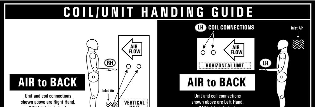
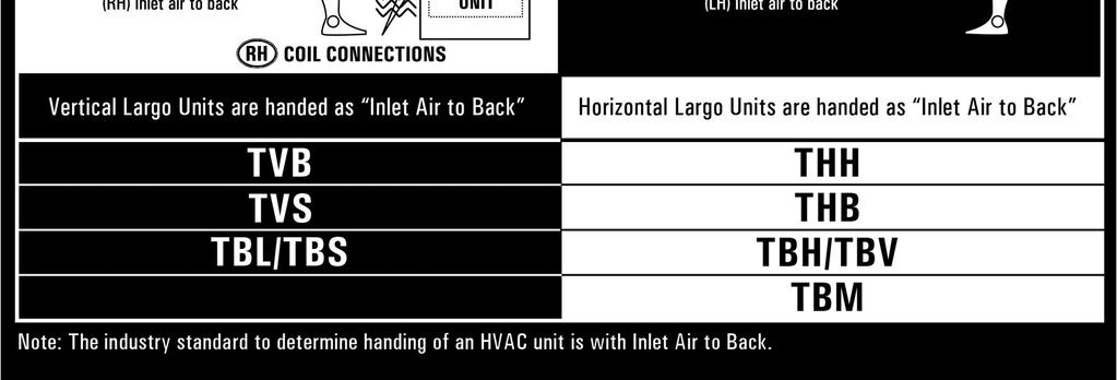
13 FCU-THBP Coil Handing

 Control Valve: 0 PSIG BPV: Balance Bypass Valve, 0 PSIG Y-STR W/ BDV: Y-Strainer NOTES: 1.")

14 FCU-THBP THBP, Piping Packages LEGEND, COMPONENT PRESSURE RATI NGS BVMS: Manual Ball Valves w/memory Stop, 0 PSIG FC: Fixed Flow Control, Device A = 0 PSIG; Device B = 0 PSIG AFS: Adjustable Flow Circuit Setter, 0 PSIG P/T Port: Pressure/Temperature Test Port, 0 PSIG Union: 1 PSIG (contact factory for 0 PSIG) Control Valve: 0 PSIG BPV: Balance Bypass Valve, 0 PSIG Y-STR W/ BDV: Y-Strainer NOTES: 1. All drawings subject to change without prior notice. 2. Diagrams show component position in relation to fluid flow. Actual valve package configuration varies with unit type, hand connection, pipe size and options. 3. 1/4" bleed line is required on 2-pipe cool and heat auto changeover systems with factory provided thermostats; optional for thermostats by others. 4. Unions provided as standard on all FW piping packages.
15 FCU-THBP THBP, Hydronic Coil Connections Right Hand 2 Pipe - Heating Only Left Hand Right Hand 2 Pipe Heating and/or Cooling Left Hand Right Hand 4 Pipe Heating & Cooling HW Coil in Re-Heat Left Hand Right Hand 4 Pipe Heating + Cooling HW Coil in Pre-Heat Left Hand Drain Outlet Detail NOTES: 1. All dimensions ± ½ [13mm]. See page 16 for dimension values. Metric valves are soft conversion. 2. All drawings subject to change without prior notice. 3. Model THBC unit shown, typical for THBP units. Connections shown are internal on THBE units. 4. Inlet and outlet connections are aligned vertically on each coil. 5. Standard externally foam coated galvanized steel drain pan has 7/8" ODM copper outlet. Stainless steel drain pan has ¾ MPT galvanized steel outlet. 6. Aux. drain outlet is 5/8" ODM cooper or 3/8" MPT galvanized steel respectively. Aux drain outlet is always on viewer s left when facing outlet end of drain pan, regardless of unit hand.


16 THBP, Hydronic Coil Connection Sizes Submittal FCU-THBP All drawings subject to change without prior notice. 2. Inlet and outlet connections are aligned vertically on each coil.

17 FCU-THBP THBP, Steam Coil Connections Right Hand 2 Pipe - Steam Only Left Hand Right Hand 4 Pipe Steam & Cooling Steam Coil in Re-Heat Left Hand Right Hand 4 Pipe Steam + Cooling Steam Coil in Pre-Heat Left Hand Drain Outlet Detail NOTES: 1. All dimensions ± ½ [13mm]. See page 18 for dimensional values. Metric valves are soft conversion. 2. All drawings subject to change without prior notice. 3. Model THBC unit shown, typical for THBP units. Connections shown are internal on THBE units. 4. Inlet and outlet connections are aligned vertically on each coil. 5. Standard externally foam coated galvanized steel drain pan has 7/8" ODM copper outlet. Stainless steel drain pan has ¾ MPT galvanized steel outlet. 6. Aux. drain outlet is 5/8" ODM cooper or 3/8" MPT galvanized steel respectively. Aux drain outlet is always on viewer s left when facing outlet end of drain pan, regardless of unit hand.


18 FCU-THBP THBP, Steam Coil Connection Sizes 1. All drawings subject to change without prior notice. 2. Inlet and outlet connections are aligned vertically on each coil.
19 FCU-THBP STANDARD FEATURES (High Performance Fan Coils) Construction All Units AHRI 4 certified and labeled Galvanized steel construction 1/2 thick fiberglass insulation 1 1/2 duct discharge collar Holes are provided at four points for hanging units Plenum units (THBP) Integral filter rack with 1 throwaway filter Integral rear ducted return Exposed units (THBE) Stamped louver supply and return air grilles Durable powder coat paint 18 gauge cabinet construction Coils Cooling - 3 to 5 row chilled water or 3 & 4 row DX, heat pump compatible Heating - 1 or 2 row hot water or steam reheat or preheat position 6 total rows of cooling and heating coils maximum 3/8" coil tube diameter 10 or 12 fins per inch High efficiency aluminum fin surface for optimizing heat transfer and air pressure drop Left or right hand, same or opposite side connections on four pipe systems Access to entering and leaving air sides for cleaning Removable for service Manual air vents Drain Pans Single wall, galvanized steel, externally insulated fire retardant and antimicrobial closed cell foam Double sloped to drain connection Removable 7/8 O.D. primary drain connection Fan Assemblies Forward curved, DWDI centrifugal type 115 volt, single phase, three tap PSC motors Quick disconnect motor connections Removable fan(s)/motor(s) for service Electrical cetlus listed for safety compliance Electrical junction box for field wiring terminations Bottom hinged electrical enclosure Electric Heat cetlus listed as an assembly for safety compliance Integral electric heat assembly with removable elements for easy service Automatic reset primary and back-up secondary thermal limits Single point power connection OPTIONAL FEATURES (High Performance Fan Coils) Construction All units Foil faced fiberglass insulation Elastomeric closed cell foam insulation Eco-Shield or Foil faced Eco-shield insulation Plenum units (THBP) Bottom return Rear Ducted return 1" Pleated filter (Merv 8) Spare 1 throwaway filters Telescoping Bottom Panels Exposed units (THBE) 1" Pleated filter (Merv 8) Single deflection bottom return grille Ducted supply and/or rear return Coils 1/2 O.D. seamless copper tubes 0.0 tube wall thickness Automatic air vents Stainless steel coil casings Drain Pans Stainless steel with external insulation 5/8 O.D. secondary drain connection Auxiliary drip pans, galvanized or stainless steel Fan Assemblies 8-2 & 277 volt, single phase, three speed PSC motors 115, 8-2 & 277 volt, single phase, three speed EC motors (THBP, THBE) 115, 8-2 & 277 volt, single phase, variable speed EC motors (THBE) Electrical SCR fan speed controller Fan relay packages / Silent solid state fan relays Toggle disconnect switch Condensate overflow switch (drain pan) Main fusing Unit and remote mounted three speed fan switches Electric Heat Manual reset secondary thermal limits Door interlocking disconnect switches Main fusing Silent relay/contactors Piping Packages Factory assembled shipped loose for field installation 1/2" and 3/4", 2 and 3 way normally closed, two position electric motorized valves Isolation ball valves with memory stop Fixed and adjustable flow control devices Unions and P/T ports Y- Strainers Floating point modulating control valves High pressure close-off actuators (1/2" = PSIG; 3/4" = PSIG) Thermostats Remote mounted analog, digital display or programmable 2 and 4 pipe control sequences Automatic and manual changeover Integral three speed fan switches
Submittal. Front View Side View
 RBHO Horizontal Low Profile Concealed Free Return Submittal FCU-RBHO-1.0 07-25-18 Top View (Drain Pan Omitted) Bottom View Front View Side View Left hand unit shown. All dimensions are inches [millimeters].
Submittal. RBHR Horizontal Low Profile Concealed with Plenum FCU-RBHR Top View (Drain Pan Omitted) Bottom View. Front View.
 Bottom View. Front View.") Horizontal Low Profile oncealed with Plenum FU-RBHR-1.0 05-11-17 Top View (rain Pan Omitted) Left hand unit shown. ll dimensions are inches [millimeters]. [8] 26 [6] 21 [533] 27 [686] 31 [787] 41 [1041]
Horizontal Low Profile oncealed with Plenum FU-RBHR-1.0 05-11-17 Top View (rain Pan Omitted) Left hand unit shown. ll dimensions are inches [millimeters]. [8] 26 [6] 21 [533] 27 [686] 31 [787] 41 [1041]
Submittal. THBP Horizontal Low Profile Plenum Return FCU-THBP Top View (Drain Pan Omitted) Bottom View. Front View.
 Bottom View. Front View.") U-THBP-.0 03-0-8 THBP Horizontal Low Profile Plenum Return Top View (rain Pan Omitted) Bottom View ront View Left hand unit shown. ll dimensions are inches [millimeters]. Side View [8] 26 [6] [06] [270]
U-THBP-.0 03-0-8 THBP Horizontal Low Profile Plenum Return Top View (rain Pan Omitted) Bottom View ront View Left hand unit shown. ll dimensions are inches [millimeters]. Side View [8] 26 [6] [06] [270]
Submittal 6 [152] 6 [152] 8 [203]
![Submittal 6 [152] 6 [152] 8 [203]](/thumbs/86/93178668.jpg "Submittal 6 [152] 6 [152] 8 [203]") TVSR Vertical High Rise Recessed Stand lone Fan Coil Unit (Do not Include Risers See note ) Submittal FCU-TVS-R-1.0 03-01- 2 - Pipe Top Views 4 - Pipe Unit Size 03 & 04 0 & 0 10 & 20 [50] 24 [10] 1 ½ [419]
TVSR Vertical High Rise Recessed Stand lone Fan Coil Unit (Do not Include Risers See note ) Submittal FCU-TVS-R-1.0 03-01- 2 - Pipe Top Views 4 - Pipe Unit Size 03 & 04 0 & 0 10 & 20 [50] 24 [10] 1 ½ [419]
RBV Sales Guide FAN COIL UNITS FLOOR-MOUNTED, VERTICAL
 RBV Sales Guide FAN COIL UNITS FLOOR-MOUNTED, VERTICAL RBVS RBVR RBVC www.superiorrex.com RBV Series: LOW POWER CONSUMPTION, ACCESSIBLE AND FLEXIBLE Owners Owners can choose between a standard or elevated
TVS/R FAN COIL UNITS HI-RISE, VERTICAL
 TVS/R FAN COIL UNITS HI-RISE, VERTICAL TVRM TVRP Riser TVRS TVSE TVSM TVSR TVSS Redefine your comfort zone. www.titus-hvac.com Redefine your comfort zone www.titus-hvac.com Model TVS/R: CONCEALED, HI-RISE
RAV Sales Guide FAN COIL UNITS HI-RISE, VERTICAL
 RAV Sales Guide FAN COIL UNITS HI-RISE, VERTICAL RAVS RARM RARS RAVE RAVM RAVL RARP RISER www.superiorrex.com RAV Series: VERTICAL HI-RISE CONCEALED SO TOUGH, WE GUARANTEE IT! www.superiorrex.com Model
FS Fan-Coil Units Hi-Rise, Vertical
 FS Fan-Coil Units Hi-Rise, Vertical FSC Concealed Dimensional Data 4-PIPE 2-PIPE TOP VIEWS Page Trims Short (5/8") Here! SIDE VIEW FRONT VIEW Dimensions Unit Size A B Single/Double Supply C D E 03 & 04
T VB FA N COIL U NIT S F LO OR -MOU NT E D, V E RT ICA L
 T VB FA N COIL U NIT S F LO OR -MOU NT E D, V E RT ICA L TVBA TVBC TVBF Redefine your comfort zone. www.titus-hvac.com Redefine your comfort zone www.titus-hvac.com Model TVB: LOW POWER CONSUMPTION, ACCESSIBLE
FW and FL Fan-Coil Units Floor-Mounted, Vertical STANDARD AND LOW PROFILE
 FW and FL Fan-Coil Units Floor-Mounted, Vertical STANDARD AND LOW PROFILE Low Power Consumption, Accessible, & FW and FL Fan-Coil Design Features Owners Owners can choose between a standard height (FW)
RBV Engineering Guide
 VERTICAL FLOOR-MOUNTED FAN COIL UNITS RBV Engineering Guide SO TOUGH, WE GUARANTEE IT. RBVS RBVC RBVR www.superiorrex.com Table of Contents Features and Benefits... 3 Construction Features... 4 Standard
Submittal DIMENSIONS SIZE FAN SIZE L W H C D E F G J K [406] [508] 25 [635] [406] 16 [406] 16 [406] 39-1/2 [1003] 44-1/2 [1130] 51 [1295] 59 [1499]
![Submittal DIMENSIONS SIZE FAN SIZE L W H C D E F G J K [406] [508] 25 [635] [406] 16 [406] 16 [406] 39-1/2 [1003] 44-1/2 [1130] 51 [1295] 59 [1499]](/thumbs/94/122284584.jpg "Submittal DIMENSIONS SIZE FAN SIZE L W H C D E F G J K [406] [508] 25 [635] [406] 16 [406] 16 [406] 39-1/2 [1003] 44-1/2 [1130] 51 [1295] 59 [1499]") BC--1.0 03-01-1 Belt Drive Blower Coil Unit, Basic Unit Discharge ARGT. 1 4. See page 1 for filter rack details. 5. Base rail is optional on he base unit. See page 13. Base rails must be used with mixing
BC--1.0 03-01-1 Belt Drive Blower Coil Unit, Basic Unit Discharge ARGT. 1 4. See page 1 for filter rack details. 5. Base rail is optional on he base unit. See page 13. Base rails must be used with mixing
New Fan Coil Piping Package. Redefine your comfort zone.
 New Fan Coil Piping Package PIPING PACKAGES Table of Contents General Notes and Legend...3 Piping Package Code Descriptions & Diagrams THB, THH and TVB Fan Coils...4 TVS Fan Coil, 2-Way...5 TVS Fan Coil,
New Fan Coil Piping Packages
 New Fan Coil Piping Packages SO BUILT TOUGH, TOUGH. WE BUILT GUARANTEE TO LAST. IT. www.superiorrex.com Piping Packages Table of Contents General Notes and Legend... 3 Piping Package Code Descriptions
PIPING PACKAGES For Chilled and Hot Water Fan Coil Units
 WWW.KRUEGER-HVAC.COM PIPING PACKAGES For Chilled and Hot Water Fan Coil Units PROVIDING YOU WITH AIR DISTRIBUTION AND EQUIPMENT SOLUTIONS TABLE OF CONTENTS General Notes... 4 Code Descriptions... 5 Guide
PIPING PACKAGES TABLE OF CONTENTS
 PIPING PACKAGES TABLE OF CONTENTS ITEM PAGE General Notes and Legend........................................................ 3 Piping Package Code Descriptions & Diagrams VAV Products and HL, HP, VF, and
FN Fan-Coil Units High-Performance, Horizontal
 FN Fan-Coil Units High-Performance, Horizontal Model FNX Exposed-Cabinet Dimensional Data Notes: 1. All dimensions are in inches [mm] and are +/- 1/8" [3 mm]. Metric values are soft conversions. 2. See
FH Fan-Coil Units Low-Profile, Horizontal
 FH Fan-oil Units Low-Profile, Horizontal FH Fan-oil Units: Innovative design simplifies installation and service Owners HRI Standard 440-certifi cation ensures exacting performance. The FH fan-coil unit
SBH / SBV Sales Guide BLOWER-COILS HORIZONTAL AND VERTICAL
 SO TOUGH, WE GUARANTEE IT. SBH / SBV Sales Guide BLOWER-COILS HORIZONTAL AND VERTICAL SBH SBV www.superiorrex.com SO TOUGH, WE GUARANTEE IT! www.superiorrex.com SBH / SBV Series: CONSTRUCTION FEATURES
RAH Engineering Guide
 FAN COIL UNITS FREE RETURN RAH Engineering Guide SO TOUGH, WE GUARANTEE IT. RAHC RAHO RAHR www.superiorrex.com Table of Contents Features and Benefits... 3 Construction Features... 4 Standard and Optional
MODULAR SINGLE AND DOUBLE WALL BELT DRIVE AIR HANDLER DX OR CHILLED WATER COOLING HOT WATER OR ELECTRIC HEATING
 MODULAR SINGLE AND DOUBLE WALL BELT DRIVE AIR HANDLER DX OR CHILLED WATER COOLING HOT WATER OR ELECTRIC HEATING SIZES FROM 600 TO 9,000 All Technical Specifications are Subject to Change without Notice.
FCVC Series VERTICAL FAN COILS
 VERTICAL FAN COILS The FCVC is designed for concealed, wall mounted installations with flexible heating/ cooling loads and minimal duct requirements. With a variety of options, such as fiber free insulation,
The Premium Quality Fan Coil Units for Horizontal Application Hydronic or Electric Heat
 Producing Quality Heating & Cooling Equipment For Over 50 Years CEA SERIES CEILING EPOSED HORIZONTAL FAN COIL UNITS The Premium Quality Fan Coil Units for Horizontal Application Hydronic or Electric Heat
Hi-Performance Series Fan Coil Technical Catalog
 Hi-Performance Series Fan Coil Technical Catalog HYB Horizontal Hideaway Furred-in with galvanized finish for ducted/high static applications in drop-ceilings or over-closets. (600-2000 CFM) HGC Horizontal
Horizontal Series Fan Coil Technical Catalog
 Horizontal Series Fan Coil Technical Catalog HCY Horizontal Hideaway 200 CFM to 200 CFM The Horizontal Hideaway (HCY) fan coil unit is designed specifically to meet the many varied requirements for a ceiling
VERTICAL SINGLE AND DOUBLE WALL BELT DRIVE AIR HANDLER DX OR CHILLED WATER COOLING WITH HOT WATER OR ELECTRIC HEAT
 VERTICAL SINGLE AND DOUBLE WALL BELT DRIVE AIR HANDLER DX OR CHILLED WATER COOLING WITH HOT WATER OR ELECTRIC HEAT SIZES FROM 600 TO 4,000 All Technical Specifications are Subject to Change without Notice.
HORIZONTAL SINGLE AND DOUBLE WALL BELT DRIVE AIR HANDLER DX OR CHILLED WATER COOLING WITH HOT WATER OR ELECTRIC HEAT
 HORIZONTAL SINGLE AND DOUBLE WALL BELT DRIVE AIR HANDLER DX OR CHILLED WATER COOLING WITH HOT WATER OR ELECTRIC HEAT MADE IN USA SIZES FROM 600 TO 9,000 All Technical Specifications are Subject to Change
Daikin McQuay. Large Capacity Fan Coil Direct Drive. HCDB, HHDB Design 1. Replacement Parts List No Revision B 03/2016
 Replacement s List 70002400 Revision B 03/206 Daikin McQuay Large Capacity Fan Coil Direct Drive HCDB, HHDB 06-20 Design To find your Daikin Applied parts distributor, call -800-377-2787 or visit www.daikinapplied.com
Daikin McQuay. Large Capacity Fan Coil Direct Drive. HCDB, HHDB Design 1. Replacement Parts List No Revision C 03/2018
 Replacement s List 700024100 Revision C 03/2018 Daikin McQuay Large Capacity Fan Coil Direct Drive HCDB, HHDB 06-20 Design 1 To find your Daikin Applied parts distributor, call 1-800-377-2787 or visit
SDL Single-Duct, Low-Height, VAV Terminals
 SDL -Duct, Low-Height, VAV Terminals SDL -Duct, VAV Terminals: Fit more comfort in less space Owners SDL terminals offer the typical benefits provided by single-duct units, while performing at extremely
Complete HVAC Capability
 Air Handling Units Brochure 1110 January 2006 Complete HVAC Capability MEA Horizontal Draw-Thru to Size 65 Vertical Draw-Thru to Size 50 1000 to 60,000 CFM Forward Curved or Airfoil Wheels Inlet Vane Option
Daikin McQuay. Large Capacity Fan Coil Belt Drive. HCBB, HHBB Design 1. Replacement Parts List No Revision E 03/2018
 Replacement s List No. 700024000 Revision E 03/2018 Daikin McQuay Large Capacity Fan Coil Belt Drive HCBB, HHBB 08-30 Design 1 To find your Daikin Applied parts distributor, call 1-800-377-2787 or visit
Product Data. Features/Benefits. 42BH System Fan Coil. 800 to 4000 Cfm
 Product Data 42BH System Fan Coil 800 to 4000 Cfm Satisfy All Your Design Requirements with Carrier s Versatile 42BH Fan Coil Unit A selection of 6 sizes covers capacities from 800 to 4000 cfm Choice of
ROOF TOP SINGLE AND DOUBLE WALL BELT DRIVE AIR HANDLER DX OR CHILLED WATER COOLING HOT WATER OR ELECTRIC HEATING
 ROOF TOP SINGLE AND DOUBLE WALL BELT DRIVE AIR HANDLER DX OR CHILLED WATER COOLING HOT WATER OR ELECTRIC HEATING MADE IN USA SIZES FROM 600 TO 9,000 All Technical Specifications are Subject to Change without
MODULAR SINGLE AND DOUBLE WALL BELT DRIVE AIR HANDLER DX OR CHILLED WATER COOLING HOT WATER OR ELECTRIC HEATING
 MODULAR SINGLE AND DOUBLE WALL BELT DRIVE AIR HANDLER DX OR CHILLED WATER COOLING HOT WATER OR ELECTRIC HEATING MADE IN USA SIZES FROM 600 TO 9,000 All Technical Specifications are Subject to Change without
Horizontal and Vertical BELT DRIVE AIR HANDLING UNITS
 Horizontal and Vertical BELT DRIVE AIR HANDLING UNITS TABLE OF CONTENTS H & V Features and Benefits...4 Coil and Filter Data, Static Pressure Data...7 Electric Resistance Heat Section...8 Coil Information
Horizontal Fan Coils 200-1,200 CFM
 Horizontal Fan Coils 200-1,200 CFM Table of Contents Williams Fan Coils & Air Handlers..................................................... 1 Horizontal Models......................................................................
BUILD YOUR REPUTATION ON OURS. Horizontal Series FAN COIL TECHNICAL CATALOG
 BUILD YOUR REPUTATION ON OURS Horizontal Series FAN COIL TECHNICAL CATALOG TABLE OF CONTENTS 2 Table of Contents 3-4 Portfolio 5 Features & Benefits Unit Model Key 7 Ratings & Listings 8 Air Delivery 9
HBC SERIES-PSC MOTOR HBCX SERIES-ECM MOTOR
 PRODUCT SPECIFICATIONS *HBC(X) *PHBC(X) *RHBC(X) *CHBC(X) Chilled Water/Hot Water 2-pipe/4-Pipe HBC SERIES- HBCX SERIES-ECM MOTOR Ceiling Concealed Horizontal -1 CFM Ceiling Concealed Ceiling Recessed
WE ARE PLEASED TO PROVIDE THE ENCLOSED SUBMITTAL FOR YOUR REVIEW AND APPROVAL
 PREPARED FOR: DATE: JOB NAME: WE ARE PLEASED TO PROVIDE THE ENCLOSED SUBMITTAL FOR YOUR REVIEW AND APPROVAL EQUIPMENT DETAILS ITEM TAG DESCRIPTION MODEL NUMBER 1 2 3 4 5 6 7 8 9 10 11 12 13 14 15 EQUIPMENT
ACTIVE CHILLED BEAM 6 1/4" HEATING 9 1/2" DISCHARGE DIRECTION. 1 7/8" u 1/4" NOZZLE SIZE:
 LINEAR 24" WIDE Submittal Sheet WATER COIL CONNECTIONS 9 1/2" 6 1/4" HEATING 9 3/8" COOLING PRIMARY AIR CONNECTION DISCHARGE DIRECTION 17 1/16" FACE WIDTH 23 3/4" 2-WAY SHOWN DISCHARGE DIRECTION MOUNTING
Product Data. 42D Ducted Fan Coil Air Conditioners cfm
 Product Data 42D Ducted Fan Coil Air Conditioners 600-2000 cfm Carrier s 42D series ducted fan coil units offer design and equipment location flexibility Choice of 5 models, each available in 8 sizes For
HBC SERIES-PSC MOTOR HBCX SERIES-ECM MOTOR
 PRODUCT SPECIFICATIONS *HBC(X) *PHBC(X) *RHBC(X) *CHBC(X) Chilled Water/Hot Water 2-pipe/4-Pipe HBC SERIES- HBCX SERIES-ECM MOTOR Ceiling Concealed Horizontal -1 CFM Ceiling Concealed Ceiling Recessed
FDCLP2 Constant Volume Series Flow, Low Profile
 The Price low profile series fan powered terminal unit is an ideal product for use in typical series fan powered applications with limited ceiling space. The is designed for constant air volume applications,
Submittal. Holder Construction Company. Reviewed. Reviewed as Noted. Rejected. 1. Updates per Bulletin #4
 Holder Construction Company 230 Peachtree Street NW, Suite 1250 Atlanta, GA 30303 Submittal Project Telephone #404.688.6233 Project Name: Submittal Number: Submittal Description: Submittal Review Date:
F SERIES. Floor Exposed Vertical Fan Coil Units. Nominal Sizes 200 thru 1200 CFM
 Producing Quality Heating & Cooling Equipment For Over 5 Years F SERIES Floor Exposed Vertical Fan Coil Units Nominal Sizes thru 1 CFM MAGIC AIRE F SERIES FAN COILS ARE ETL LISTED TO U.S. AND CANADIAN
SECTION AIR TERMINAL UNITS
 SECTION 23 36 00 AIR TERMINAL UNITS PART 1 - GENERAL 1.1 SUMMARY A. Section includes constant volume terminal units, variable volume terminal units, dual duct terminal units, fan powered terminal units,
A I R H A N D L E R S CB26UH-R. MERIT Series R-22 - Upflow / Horizontal P R O D U C T S P E C I F I C AT I O N S
 P R O D U C T S P E C I F I C AT I O N S A I R H A N D L E R S CB6UH-R MERIT Series R- - Upflow / Horizontal Bulletin No. 1067 April 01 Supersedes January 01 Nominal Capacity - 1.5 to 5 Tons Optional Electric
Vertical Stack Fan Coils 300-1,200 CFM
 Vertical Stack Fan Coils 300-1,200 CFM Table of Contents Williams Fan Coils & Air Handlers... 1 Vertical Stack Models... 2 Features & Benefits... 4 Equipment Options... 5 ARI Cooling Capacity... 6 Heating
B. Base occupied space sound level estimates on ARI 885. C. Terminal heating coils shall conform to ARI 410.
 PART 1 - GENERAL 1.01 Purpose: A. This standard is intended to provide useful information to the Professional Service Provider (PSP) to establish a basis of design. The responsibility of the engineer is
catalog SDL Single-Duct, Low-Height, VAV Terminals
 catalog SDL Single-Duct, Low-Height, VAV Terminals TABLE OF CONTENTS Features and Benefits.... 2 Controls.... 3 Construction Features... 4 Standard and Optional Features.... 5 Dimensional and Weight Data....
TSS Single-Duct VAV Terminals
 TSS Single-Duct VAV Terminals Model TSS construction features Standard Construction Mechanical-lock construction ensures lowest possible casing leakage Roll-formed inlet collar with integral stiffening
Chilled Water FCU. Horizontal Fan Coil 50hz CFM. A Series.
 Chilled Water FCU A Series 3-25 CFM Horizontal Fan Coil 5hz www.windind.com CONTENTS GENERAL CONSTRUCTION... 3 MODEL NUMBER NOMENCLA TURE... 4 DIMENSIONS... 5 FAN PERFORMANCE DATA... 7 GENERAL SPECIFICATIONS...
Precision Cooling For Business-Critical Continuity. Liebert CW. System Design Manual kW, 50 & 60Hz
 Precision Cooling For Business-Critical Continuity Liebert CW System Design Manual - 26-181kW, 50 & 60Hz TABLE OF CONTENTS LIEBERT CW MODEL NUMBER NOMENCLATURE....................................1 1.0
CFFWA Chilled/Hot Water Universal Mount Fan Coil 2-Pipe Heat / Cool Fan Coil 12,000-60,000 BTUH
 CFFWA Chilled/Hot Water Universal Mount Fan Coil 2-Pipe Heat / Cool Fan Coil 12,000-60,000 BTUH 207 CFFWA NOMENCLATURE BREAKDOWN 2-Pipe Heat/Cool Universal Mount Fan Coil CFFWA- XX - 1 - U 2-Pipe Heat/Cool
UNITAIRE IV FAN COIL UNITS. High Quality Engineered Fan Coils Since 1931
 UNITAIRE IV FAN COIL UNITS High Quality Engineered Fan Coils Since 1931 Table of Contents Design Features... 3 Nomenclature...4-5 Units...6-8 Construction Features...9 Physical Data and Motor Data... 10-11
A Division of Nailor International Inc. ECONOMY AIR HANDLERS
 A Division of Nailor International Inc. MODEL : ECONOMY AIR HANDLERS Thermal Model Standard Specification MODEL 800-4000 CFM AIR HANDLERS Description Model air handlers are designed for efficient and economical
catalog SDL Single-Duct, Low-Height, VAV Terminals
 catalog SDL Single-Duct, Low-Height, VAV Terminals Catalog: ET130.13-EG2 (708) TABLE OF CONTENTS Single-Duct, Low-Height VAV Terminals Features and Benefits....................... 2 Controls..................................
NORTHWESTERN UNIVERSITY PROJECT NAME JOB # ISSUED: 03/29/2017
 SECTION 23 3600 - AIR TERMINAL DEVICES PART 1 - GENERAL 1.1 SUMMARY A. Section Includes: 1. Fan-powered air terminal units/devices. 2. Shut off air terminal units/devices. 3. Dual duct terminal units/devices.
Consider The Possibilities...
 FS/FD Air-Cooled Fluid Cooler Catalog 710.1 Consider The Possibilities... Cools most any non-corrosive fluid Closed-circuit cooling avoids contamination Cold weather economizer for interior cooling loads
BVX SERIES VERTICAL DIRECT EXPANSION BLOWER COIL UNITS
 BVX SERIES VERTICAL DIRECT EXPANSION BLOWER COIL UNITS MAGIC AIRE BVX SERIES FAN COILS ARE ETLC LISTED IN ACCORDANCE WITH UL 1995 AND ARE ASSEMBLED TO ORDER FOR COMPETITIVE DELIVERY. UNITED ELECTRIC COMPANY,
HORIZONTAL HIGH CAPACITY FAN COIL UNITS DUCTED
 Direct Drive, Draw-through Design Model Series 3FH Filter 1" (2) throwaway (standard) 2" (1) MERV 8 or MERV 13 pleated (optional) Multiple coil options: 3, 4,, 6 row cooling or heating coils 1 or 2 row
Daikin McQuay. Thinline Horizontal Fan Coils and Cabinet Unit Heaters. FCHC, FCHH, FCHR FHHC, FHHH, FHHR 02, 03, 04, 06, 08, 10, 12 Design 1
 Replacement Parts List No. 700026400 Revision N 01/2018 Daikin McQuay Thinline Horizontal Fan Coils and Cabinet Unit Heaters FCHC, FCHH, FCHR FHHC, FHHH, FHHR 02, 03, 04, 06, 08, 10, 12 Design 1 To find
DECORATIVE FAN COIL UNIT DECORATIVE FAN COIL UNIT SPECIFICATIONS
 DECORATIVE FAN COIL SPECIFICATIONS UNIT CABINET Single skin or double skin casing (inner perforated sheet or flat sheet) made of powder coated galvanized steel assembled in aluminum extrusion profiles,
FAN TERMINAL UNITS Constant Volume (Series Flow), Standard Design
, Standard Design") FAN TERAL UNITS Constant Volume (Series Flow), Standard Design Models ACF w/o Coil ACW w/hot Water Coil ACE w/electric Coil The Carnes constant volume fan terminal unit provides constant air volume to
FAN TERAL UNITS Constant Volume (Series Flow), Standard Design Models ACF w/o Coil ACW w/hot Water Coil ACE w/electric Coil The Carnes constant volume fan terminal unit provides constant air volume to
DIRECT EXPANSION COMMERCIAL PACKAGED AIR HANDLING UNITS, 6 25 TONS
 Product Specifications DIRECT EXPANSION COMMERCIAL PACKAGED AIR HANDLING UNITS, 6 25 TONS BUILT TO LAST, EASY TO INSTALL AND SERVICE Multi position design for horizontal or vertical installation without
August PRODUCT DESIGN GUIDE Inteli-line Vertical Stack Fan Coil with Slide-Out Chassis
 August 2018 PRODUCT DESIGN GUIDE with Slide-Out Chassis Table of Contents with Slide-Out Chassis Cabinet Nomenclature 1 Chassis Nomenclature 2 AHRI Performance Rating 3 Features & Benefits 4 Physical Data
University of Delaware
 SECTION 23 36 00 _ SUMMARY PART 1 GENERAL 1.1 SUMMARY A. Section Includes: 1. Constant/Variable volume supply terminal units. 2. Fan powered terminal units. 3. Exhaust valves B. Related Sections: Section
DIRECT-DRIVE BLOWER FAN COIL AIR CONDITIONER ENGINEERING GUIDE
 DIRECT-DRIVE BLOWER FAN COIL AIR CONDITIONER ENGINEERING GUIDE Model: YSHW-DD 00784VIP Introduction YORK DIRECT DRIVE FAN COIL UNITS The YORK Fan Coil Unit is designed for many exposed and concealed applications.
Daikin. PreciseLine Horizontal Large Capacity Blower Coil. BCHD Design 1. Replacement Parts List No Revision A 03/2019
 Replacement Parts List No. 700053700 Revision A 03/2019 Daikin PreciseLine Horizontal Large Capacity Blower Coil BCHD 030-050 Design 1 To find your Daikin Applied parts distributor, call 1-800-377-2787
36CWA4-HW 4-Pipe Chilled & Hot Water Air Handler (120V) 4-Pipe Heat & Cool Fan Coil 36,000 BTUH
 4-Pipe Heat & Cool Fan Coil 36,000 BTUH") 36CWA4-HW 4-Pipe Chilled & Hot Air Handler (120V) 4-Pipe Heat & Cool Fan Coil 36,000 BTUH Rev. 1.2 HVAC Guide Specifications Chilled & Hot Multi-Position Fan Coil 4-Pipe Nominal Size: 36,000 BTUH Multiaqua
36CWA4-HW 4-Pipe Chilled & Hot Air Handler (120V) 4-Pipe Heat & Cool Fan Coil 36,000 BTUH Rev. 1.2 HVAC Guide Specifications Chilled & Hot Multi-Position Fan Coil 4-Pipe Nominal Size: 36,000 BTUH Multiaqua
"SPOAU" DEDICATED 100% OUTSIDE AIR UNITS Self Contained Single Package or Split System Units
 "SPOAU" DEDICATED 100% OUTSIDE AIR UNITS Self Contained Single Package or Split System Units Spinnaker Industries Inc. Model Series SPOAU 100% Outdoor Air Systems shall be factory assembled, wired and
24CWA4-HW 4-Pipe Chilled & Hot Water Air Handler (120V)
") 24CWA4-HW 4-Pipe Chilled & Hot Air Handler (120V) 4-Pipe Heat & Cool Fan Coil 24,000 BTUH Rev. 1.2 HVAC Guide Specifications Chilled & Hot Multi-Position Fan Coil 4-Pipe Nominal Size: 24,000 BTUH Multiaqua
24CWA4-HW 4-Pipe Chilled & Hot Air Handler (120V) 4-Pipe Heat & Cool Fan Coil 24,000 BTUH Rev. 1.2 HVAC Guide Specifications Chilled & Hot Multi-Position Fan Coil 4-Pipe Nominal Size: 24,000 BTUH Multiaqua
HOW TO SPECIFY SDV UNITS
 HOW TO SPECIFY SDV UNITS MODEL UNIT CONFIG LINER CASING OPTIONS CONST. SIDE INLET SIZE DISCHARGE OPTIONS CONTROL TYPE UNIT ACCESSORIES HEAT kw ELECTRIC HEAT ACCESSORIES SCR HEAT ACCESSORIES SDV 0 - Standard
McQuay. Seasonmaker Horizontal Fan Coil. TSC Vintage G. Last Manufactured: Replacement Parts List No Revision C 08/2016
 Replacement Parts List 057117500 Revision C 08/2016 McQuay Seasonmaker Horizontal Fan Coil TSC 021-121 Vintage G Last Manufactured: 1997 To find your Daikin Applied parts distributor, call 1-800-377-2787
FFW/FSW/FHW SERIES FLOOR EXPOSED VERTICAL FAN COIL UNITS
 FFW/FSW/FHW SERIES FLOOR EXPOSED VERTICAL COIL UNITS MAGIC AIRE FFW/FSW/FHW/FHW SERIES COILS ARE ETLC LISTED IN ACCORDANCE WITH UL 995 AND ARE ASSEMBLED TO ORDER FOR COMPETITIVE DELIVERY. UNITED ELECTRIC
OmegaAir Series Dedicated Outside Air Systems (DOAS) Engineering Guide
 Engineering Guide") Series Dedicated Outside Air Systems (DOAS) Engineering Guide Effective September 2017 Vertical and Horizontal Water-Cooled and Air-Cooled Contents Product Features...3 Options...4 Air-Cooled Indoor Ducted
Series Dedicated Outside Air Systems (DOAS) Engineering Guide Effective September 2017 Vertical and Horizontal Water-Cooled and Air-Cooled Contents Product Features...3 Options...4 Air-Cooled Indoor Ducted
MH1WC4W-08-1-B Chilled/Hot Water 1-Way Cassette Fan Coil
 MH1WC4W-08-1-B Chilled/Hot Water 1-Way Cassette Fan Coil 4-Pipe Heat / Cool Fan Coil 24,000 BTUH Rev. 1.11 HVAC Guide Specifications Chilled and Hot Water Cassette Fan Coil 4-Pipe Nominal Size: 24,000
DESCRIPTION ACCESSORIES FIELD INSTALLED SPLIT-SYSTEM EVAPORATOR BLOWERS KBBU060, KDBC090, KCBC120 & KCBC180 5 THRU 15 NOMINAL TONS SUPPLY AIR PLENUMS
 DESCRIPTION TECHNICAL GUIDE SPLIT-SYSTEM EVAPORATOR BLOWERS KBBU060, KDBC090, KCBC120 & KCBC180 5 THRU 15 NOMINAL TONS These completely assembled units include a well-insulated cabinet, a DX cooling coil
RERV & RERVX RERVLP. Rotary Energy Recovery Ventilators. Low Profile Indoor Rotary Energy Recovery Ventilators
 Version: Dec. 01, 2004 RERV & RERVX Rotary Energy Recovery Ventilators Indoor and Outdoor Installations 250 20,000 CFM Capacities RERVLP Low Profile Indoor Rotary Energy Recovery Ventilators Ideal for
Vertical Hi-Rise Fan Coil Unit (Model FS)
") Technical Bulletin Issue Date March 1, 2005 Vertical Hi-Rise Fan Coil Unit (Model FS) Model FS Vertical Hi-Rise fan coil units are designed to maximize flexibility of selection and installation. The units
Technical Bulletin Issue Date March 1, 2005 Vertical Hi-Rise Fan Coil Unit (Model FS) Model FS Vertical Hi-Rise fan coil units are designed to maximize flexibility of selection and installation. The units
 Issue 4 (Record Only) Job #: Innovent Submittal Date: October 30, 2012 Project: Location: Columbus, OH Innovent Job #: Submittal Issue: 4 (Record Only) Engineer: Contractor: Tag Innovent Model # AHU-BG-01
Air-Cooled Fluid Cooler
 Catalog KM-FSD-0313A FS/ FD Series Air-Cooled Fluid Cooler Consider The Possibilities Cools most any non-corrosive fl uid Closed-circuit cooling avoids contamination Cold weather economizer for interior
Climas y Proyectos Leyco, S.A. de C.V.
 GENERAL DESCRIPTION : FURNISH AND INSTALL MULTI COMPONENT ROOF MOUNTED LEYCO, MODEL CAH CUSTOM AIR HANDLER MADE SELF-CONTAINED, WEATHER RESISTANT, AIR HANDLING UNITS PER MODEL NUMBER, AND PERFORMANCE DATA
48CWA2-00 Chilled Water Fan Coil With or Without Electric Heat 2-Pipe Heat / Cool Fan Coil 48,000 BTUH
 48CWA2-00 Chilled Water Fan Coil With or Without Electric Heat 2-Pipe Heat / Cool Fan Coil 48,000 BTUH Rev. 1.3 HVAC Guide Specifications Chilled or Hot Water with Optional Electric Heat Multi-Position
ELITE SERIES R-410A Ready - Multi-Position
 PRODUCT SPECIFICATIONS AIR HANDLERS CBXM ELITE SERIES R-0A Ready - Multi-Position Bulletin No. 0 October 07 Supersedes June 0 Nominal Capacity -. to Tons Optional Electric Heat -. to 0 kw MODEL NUMBER
FAN POWERED TERMINAL UNITS
 Benefits: Fan powered terminals are typically used for heating and cooling of perimeter zones. Operating cost savings can be achieved through the use of waste heat recovery from the ceiling plenum and
PHCD-Series. Catalog
 PCD-Series Catalog odel: PCD Introduction PCD fan coil unit is designed for a fully concealed ceiling installation. The external static pressure(esp) is up to 75Pa. Owing to its low static and low noise,
MAH. Modular Air Handling Unit
 MA Modular Air andling Unit 500 to 11,000 CFM @ up to 6.00 TSP 2 and 4 double wall construction, perforated or solid lined 18 gauge G0 galvanized steel cabinet 26 standard cabinet sizes available Internally
Typical Applications. Horizontal Installation
 ENGINEERING DATA COILS COIL UNITS CB19 AND CBH19 SERIES UP-FLOW, DOWN-FLOW AND HORIZONTAL COIL UNITS *12,600 to 65,500 Btuh (3.7 to 19.2 kw) Cooling Capacity 11,500 to 60,000 Btuh (3.4 to 17.6 kw) Heat
This series of H/ERVs is highly customizable and purpose built for the project it was designed into. See the nomenclature details that follow.
 NU2540 ERV Specifications Available Options CUSTOMIZATION: This series of H/ERVs is highly customizable and purpose built for the project it was designed into. See the nomenclature details that follow.
High Performance Fan Coils FCHG Genesis Series Horizontal
 Dimensional Data 5 7 /8 (150) D 14 (356) 2 (51) Diverter - Slides Into Discharge Ductwork Optional: Second Drain Pan Connection E Coil Section X Dimensional Data - IP (in.) / SI [mm] Unit Fan Outlet Duct
BHH Product Specifications
 BHH Product Specifications HORIZONTAL BELT DRIVE DIRECT EXPANSION BLOWER COIL UNITS ALL S 3, 4, and 5 Ton 208/230 3 60 and 460 3 60 supply voltage Units are ETL listed to U.S. and Canadian safety standards
forward curved inline duct blowers
 Defining Innovation. forward curved inline duct blowers TYPE DBS (Single) DBT (Twin) BULLETIN 4220 January 2011 Duct Blowers General Information Twin City Fan s belt driven DBS (single) and DBT (twin)
FAN POWERED SERIES FCI-600 CONSTANT VOLUME FAN TERMINAL UNIT SPECIFIABLE FEATURES
 FAN TERMINAL UNIT SPECIFIABLE FEATURES Galvanized steel casing, mechanically sealed for low leakage construction NEMA TYPE 1 rated hinged control enclosure with standoff to prevent penetration of casing
VAHU Vertical Air Handling Unit
 500 to 5,400 CFM @ up to 6.00" TSP 2" double wall construction, perforated or solid lined 18 gauge G90 galvanized steel cabinet 4 standard cabinet sizes available Internally isolated direct drive plug
 Unit Sequence Tier 1 DP
 SINGLE PACKAGE AIR CONDITIONING WATER COOLED
 MODELS: CU060-300 5-25 TONS VERTICAL SINGLE PACKAGE AIR CONDITIONING WATER COOLED MODELS: CH060-5-10 TONS HORIZONTAL FOR DISTRIBUTION USE ONLY - NOT TO BE USED AT POINT OF RETAIL SALE TABLE OF CONTENTS
Product Data. Features/Benefits. 42C,D,S,V Series Fan Coil Air Conditioners 50/60 Hz. 150 to 2000 cfm
 Product Data 2C,D,S,V Series Fan Coil Air Conditioners 50/60 Hz 150 to 2000 cfm 2SH STACK 2CA HORIZONTAL 2DA DUCTED 2VB VERTICAL Carrier s 2C,D,S,V Series fan-coil units combine design flexibility with
A. NU2035 HRV Specifications NU2035
 A. NU2035 HRV Specifications NU2035 B. Available Options CUSTOMIZATION: This series of H/ERVs is highly customizable and purpose built for the project it was designed into. See the nomenclature details