Service Manual. APU Model MTS-T4-6
|
|
|
- Leonard Haynes
- 5 years ago
- Views:
Transcription


1 Service Manual APU Model MTS-T4-6
2
3 Table of Contents Introduction Section Page # Preface S0.1 Preface i Safety S0.2 Safety i Section 1 Specifications APU Dimensions S1.0 1 Fluid Capacities and Requirements S1.1 2 Air Conditioning Specifications S1.2 4 Other Technical Specifications S1.3 5 Section 2 Maintenance Introduction to Maintenance S2.0 6 Maintenance Schedule S2.1 7 Maintenance Checklist S2.2 8 Cross Reference Consumable Parts List S2.3 9 Serpentine Drive Belt S Fan Belt Removal and Adjustment S Oil Change S Replacing the Fuel Filter S Replacing the Air Filter S Breaker Reset Instructions S Cleaning Instructions S Cleaning the 120 Volt AC Generator S Cleaning the HVAC Filter S Section 3 Serpentine Drive Introduction to the A/C Compressor Serpentine Drive System S Remove/Replace Flywheel Pulley S Section 4 Frame and Enclosure Enclosure Introduction S Frame and Enclosure Main Components S Engine Mounting Bracket Assembly S Rubber Engine Mount Assembly Sequence S APU Side Panels S APU Cover and Latches S Bottom Cover and Oil Drain Plate S Frame and Enclosure (Outside) Parts List S Frame and Enclosure (Inside) Parts List S November 2015 RigMaster Power International Ltd. Table of Contents i
4 Table of Contents Section 5 General Engine Section Page # Introduction to Engine Repairs S Glow Plugs S Fuel Filter Assembly S Fuel Solenoid S Front and Rear Oil Seal Replacement S Starter Motor S Alternator S Timing Belt S Section 6 Fuel System Fuel System Introduction S Bleeding Procedure: Low Pressure Fuel System S Standard Fuel System Configuration S Fuel System Test Procedures S Section 7 Air Filter Air Filter S Removing and Replacing the Air Filter S Section 8 Exhaust System Engine Exhaust S Removing/Installing the Exhaust Flex Pipe S Horizontal Muffler Mounting S Diesel Particulate Filter (DPF) System S Section 9 DC Electrical Engine Electrical and Control System (General Information) S Operation of the Electronic Control System S Electronic Control Operation and Fault Codes S General Electrical System Information S Power Module Connections S System Schematics S Testing the Electric Coolant Control S Blower Motor Wiring S Alternator Charging S Sensors, Switches, and Sending Units S Battery Fuse S November 2015 RigMaster Power International Ltd. Table of Contents ii
5 Table of Contents Section Volt Generator Section Page # Generator Electrical System Specifications S Generator Mounting Diagrams S Generator Removal and Installation S Testing the Generator S Adjusting the Engine Idle S Generator Diagnostics Procedures S Generator Service Procedures S Generator Wiring Electrical Schematics S Cables and Outlets S Section 11 Air Conditioning System Air Conditioning System Overview S Air Conditioning System Operation and Specifications S Air Conditioning System Hoses and Components Diagram S Air Conditioning Hose Installation S Air Conditioning Diagnostics S New Installation and Compressor Replacement S Air Conditioning System Flushing Procedure S Section 12 Heating and Cooling Engine Cooling System Overview S Cooling System Draining, Flushing and Refilling S Cooling System Electrical Components S Troubleshooting a Coolant Leak S Heating System S Section 13 Troubleshooting Engine S Charging System S Fuel System S Cooling System S HVAC System S Volt Generator System S Serpentine Drive Belt S Digital Speed Sensor S Fault Codes S Additional Information for E28 Error Code Troubleshooting S November 2015 RigMaster Power International Ltd. Table of Contents iii
6 Preface S0.1 Preface Scopes and Purpose These are non-binding service procedures that are intended to support authorized RigMaster APU trained dealers and service personnel in the maintenance, installation and servicing of the Model MTS-T4-6 auxiliary power units. These instructions apply to all class 8 O.T.R. vehicles, unless technical modifications on the vehicle influence the serviceability. Depending on the version and vehicle equipment, changes in procedure and diagnosis may be required that are set outside this manual. In any event the directives in the service manual must be followed and acknowledged engineering conventions must be observed when performing service and maintenance work. It is expected that the technician have a comprehensive set of tools and experience suited to automotive diagnostic and service work. Definitions NOTE A NOTE describes important information necessary to properly complete a procedure, or information which will make the procedure easier to understand. CAUTION A CAUTION describes a special procedure or special steps which must be taken while completing a task. Disregarding a CAUTION may result in damage to the assembly. WARNING! A WARNING describes a special procedure or steps, which must be taken while completing the procedure where the warning is found. Disregarding a WARNING can result in serious personal injury or death. November 2015 RigMaster Power International Ltd. S0.1 Preface i
7 Preface Additional Publications Model MTS-T4-6 APU Owners Manual Model MTS-T4-6 APU Installation Manual Model MTS-T4-6 APU Warranty Handbook Visit for Engine KDW702 Owner & Service Manuals. Licensed dealerships may review and download additional publications by logging into their Dealer portal. NOTE Owner s manuals and APU Parts Lists are publicly accessible and downloadable: go to hold your cursor over the customer support tab and select support materials. This manual is divided into sections by engine and assembly systems, with a section dedicated to the preventative maintenance of the APU. For detailed information on installation please refer to the Model MTS-T4-6 APU Installation Manual. For detailed information on engine service please refer to the Kohler Service Manual. Read this entire manual prior to performing service and maintenance procedures. If you do not fully understand how to perform a process or procedure or require additional help please contact our Technical Support Department before proceeding. Technical Assistance Before calling for technical assistance please have ready the following: 1. Current MTS-T4-6 Service Manual 2. Model MTS-T4-6 Serial Number 3. Unit Hour Meter Reading 4. Service & Repair History (if available) Technical Support is available by Telephone: (888) or (416) Monday to Friday from 8:00 a.m. to 5:00 p.m. Eastern Standard Time and Website: (click: Customer Support, Support Materials, Technical Support) November 2015 RigMaster Power International Ltd. S0.1 Preface ii

8 Safety S0.2 Safety 1. Zero Energy State NOTE: ZERO ENERGY STATE To perform service, maintenance and repairs you must disconnect the RigMaster from its battery source. In the recommended installation configuration the RigMaster shares the battery bank with the vehicle's main engine. Unplug the J1 harness at the power module before disconnecting the battery cables. After disconnecting the battery cables, check the battery posts inside the RigMaster engine cabinet to confirm there is no voltage to the auxiliary power unit (APU). 2. Safety Cover Switch WARNING!: SAFETY COVER SWITCH It is critical that this safety cover switch is never bypassed; failure to comply may result in serious injury. Figure 0-1 Safety Cover Switch The safety cover switch (See Figure 0-1) is designed to prevent the RigMaster Power APU from starting when the engine cover is loose or has been removed. When the cover is down, the switch is in the closed position. When the cover is open or loose, the switch is in the open position. The switch is located at the very top of the unit enclosure on the surge tank bracket. 3. AutoStart Automatic Start/Stop Feature CAUTION: AUTOSTART FEATURE Remember that a properly functioning RigMaster is capable of starting independently of its operator. If the AutoStart feature is enabled, battery voltage, temperature, and time of day can all cause the RigMaster s engine to start. Please see the cabin controller operating instructions for further information on the AutoStart feature. You must deactivate this feature prior to refueling. 4. Engine Hoist Points NOTE: ENGINE HOIST POINTS The Kohler engine has hoist points that are useful for removal and reinstallation of the engine. It is advised that these hoist points should only be used if no other means of lifting the unit are available. November 2015 RigMaster Power International Ltd. S0.2 Safety i
9 Safety 5. Starting Aids WARNING! Do not use any type of starting aids such as ether. Such use could result in an explosion and personal injury, and will render the APU warranty null and void. 6. Starting with the Cover Off CAUTION Some installation or repair/diagnostic procedures require that the APU is started with the engine cover off. Do not deactivate or bypass the safety cover switch. Instead, have another individual assist by manually holding the safety cover switch down in the closed position for the duration of the procedure. 7. Inspection of the Safety Systems The safety systems on the RigMaster APU should be examined and tested prior to performing any service work and at 50 hour intervals to ensure that they are in good condition and proper working order. 8. Safe Working Practices Safe working practices are your responsibility. The use of protective safety equipment is mandatory when performing inspections, service, diagnostics and repairs on the RigMaster APU. Follow your local regulations and guidelines regarding occupational health and safety. 9. Contact Us If you do not fully understand this safety information contact RigMaster s Technical Support Department toll free at (888) before proceeding with the operation or service of this APU. November 2015 RigMaster Power International Ltd. S0.2 Safety ii


10 Specifications Section 1 Specifications Section Page APU Dimensions S1.0 1 Fluid Capacities and Requirements S1.1 2 Air Conditioning Specifications S1.2 4 Other Technical Specifications S1.3 5 S1.0 APU Dimensions APU Certified Weight Heating Capacity Air Conditioning Capacity DC Charging Capacity Figure 1-1 SPECIFICATIONS 410 lbs. 13,500 BTU 24,000 BTU 12 Volt, 60 Amp. ENGINE ENCLOSURE Width 25" Height 28½" Depth 25" Overall 28½" 25" Figure 1-2 HVAC UNIT See Figure ,000 BTU Width 15½" Height 8½" Depth 12½" Blower Motor 600 CFM November 2015 RigMaster Power International Ltd. Section 1 Specifications 1
11 Specifications S1.1 Fluid Capacities and Requirements OIL S.A.E./(S.I.) Volume 5 Liters / 5.3 US Quarts Type API CF4 - CG4 Oil Viscosity Variable: See Figure 1-3 NOTE Recommended Lubricant for Fuel with Low Sulfur Content: API CF4 - CG4 (Regions in which diesel normally has a low sulfur content: Europe, North America, and Australia). CAUTION Consult a RigMaster Dealer about the use of synthetic oil in your RigMaster. Service intervals for oil and oil filter replacements are 1000 hours. Synthetic oil is suitable for use; however, it is recommended that mineral-based oils are used for the break-in period. Oil Viscosity vs. Temperature Figure W30 and 15W40 are the most commonly used grades of oil. Low viscosity oil must be used in lower temperatures. ENGINE COOLANT Engine Coolant TYPE 50/50 mixture of ethylene glycol based, low silica, diesel specific antifreeze and distilled water. Use only coolants suitable for aluminum core radiators. Fuel Type Biodiesel FUEL SPECIFICATIONS Ultra Low Sulfur Diesel (ULSD) Tier 4 engines 20% R.M.E. November 2015 RigMaster Power International Ltd. Section 1 Specifications 2
12 Specifications Use of Biodiesel Fuel Fuels containing less than 20% methyl ester or B20, are suitable for use in this engine. Biodiesel fuels meeting the specification of BQ-9000, EN or equivalent are recommended. Additionally: No mixture above the listed percentage for the Tier 4 engine is acceptable, as this can result in filter blocking. Fuel storage must be to recommended standards, to avoid the absorption of water, and degradation. In any event, storage should not exceed twelve (12) months. Fuel degradation, if allowed to occur, can result in the corrosion of metallic components, and the premature failure of seals. RME is a powerful solvent. Damage may occur if it comes into contact with paint. CAUTION DO NOT use vegetable oil as a biofuel for this engine. No legal liability can be accepted for failure attributable to operating products with fuels for which the products were not designed, and no warranties or representations are made as to the possible effects of running these products with such fuels. Noncompliance of the fuel to agreed standards, whether being evident by appearance of the known degradation products of these fuels, or their effects within the fuel injection equipment, will render the manufacturer's guarantee null and void. If you require further information, please contact your local RigMaster Dealer. November 2015 RigMaster Power International Ltd. Section 1 Specifications 3
13 Specifications S1.2 Air Conditioning Specifications Quick Reference See Section 11 The RigMaster air conditioner is also fully automatic. A constant comfort zone is maintained with the temperature selector setting (see Cabin Controller Operating Instructions). The RigMaster air conditioner is an R134a system that is not integrated into the vehicle's existing air conditioning system. WARNING! ONLY CERTIFIED AIR CONDITIONING TECHNICIANS SHOULD SERVICE THE AIR CONDITIONER. HIGH PRESSURE VS. TEMPERATURE READINGS High temperatures and pressures are approximate. Readings within 10-15% (See Figure 1-4) will deliver acceptable performance. Air Conditioning Performance Figure 1-4 SUCTION PRESSURES LOW SIDE Usual low side pressure PSI depending on outside temperature and humidity. DISCHARGE PRESSURES HIGH SIDE Usual high side pressure PSI depending on outside temperature and humidity. AIR CONDITIONING Refrigerant Type Volume of Refrigerant (24,000 BTU HVAC) Compressor Oil Type Compressor Oil Capacity (already filled with 3.3 oz.; add an extra 2 oz. at time of charging) Evaporator Temperature Switch Binary Pressure Switch SPECIFICATIONS R134a 1.0 lb.; (16 oz.; 0.4 Kg.) SP46 to 100 PAG Compressor Oil 6.3 fl. oz.; (186.3 cc.; ml.) Range = 30 F to 42 F (-1 C to 7 C) Range = 28 to 450 psi November 2015 RigMaster Power International Ltd. Section 1 Specifications 4

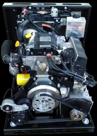
14 Specifications S1.3 Other Technical Specifications This section lists only basic information about the Kohler engine. Please see the Kohler Service Manual for detailed information on engine specifications. KOHLER ENGINE SPECIFICATIONS Cylinders Qty. 2 Bore 75 mm Stroke 77.6 mm Displacements 686 cm 3 Compression rate 22.8:1 APU HP 10.5 APU 2400 N 80/1269/CEE-ISO (17.0) Maximum Power NB ISO IFN 11.7 (16) NA ISO ICXN 10.7 (14.5) Maximum torque at NB power RPM Maximum Torque N o 3 PTO 3600 RPM 37@1800 Nm Specific fuel consumption referred to NB power 320 g/kwh Oil consumption measured at NA power 0,009 Kg/h Dry weight of engine 66 Kg (145.5 lbs.) Combustion air volume at 3600 RPM 1240 l./1' Cooling air volume at 3600 RPM 43 m 3 /mm Axial load allowed on crankshaft (both directions) 300 Kg Instant operation (up to 1 min.) 35 α Maximum Tilt Intermittent operation (up to 30 min.) 25 α Permanent operation Depends on application SENSORS/SWITCHES Quick Reference Oil Pressure Switch (Normally Open) Engine Temperature Switch (Normally Open) Safety Cover Switch Coolant Low Volume Float Switch (Normally Open) Evaporator Thermostatic Switch Binary Safety Pressure Switch SPECIFICATIONS Switch Open Normal Pressure Switch Closed Low Pressure (less than 5.7 psi) Switch Open Normal Temperature less than 230 F (110 C) Switch Closed High Temperature more than 230 F ± 5 F (110 C ± -15 C) Switch Open Cover is Off Switch Closed Cover is On Switch Open Coolant Full Switch Closed Coolant Low Switch Open Evaporator 31 F ± 2 F (-0.5 C ± -16 C) Switch Closed Evaporator 39.5 F ± 2 F (4 C ± -16 C) Closed between 28 and 450 psi Kohler Engine (KDW 702) Figure 1-5 November 2015 RigMaster Power International Ltd. Section 1 Specifications 5
15 Maintenance Section 2 Maintenance Section Page Introduction to Maintenance S2.0 6 Maintenance Schedule S2.1 7 Maintenance Checklist S2.2 8 Cross Reference Consumable Parts List S2.3 9 Serpentine Drive Belt S Fan Belt Removal and Adjustment S Oil Change S Replacing the Fuel Filter S Replacing the Air Filter S Breaker Reset Instructions S Cleaning Instructions S Cleaning the 120 Volt AC Generator S Cleaning the HVAC Filter S S2.0 Introduction to Maintenance The following service procedures describe the replacement of basic service components and general maintenance of the MTS-T4-6. The maintenance schedule must be adhered to in order to maintain the manufacturers warranties. Do not use unapproved cross-reference parts while performing maintenance or repair. The maintenance checklist S2.2 mentions service procedures for MTS-T4-6 s equipped with the optional Diesel Particulate Filter (DPF). These DPF maintenance items only apply to MTS-T4-6 units equipped with DPF s. November 2015 RigMaster Power International Ltd. Section 2 Maintenance 6
16 Maintenance S2.1 Maintenance Schedule The first oil change must be performed at 100 hours of service and at 1000 hour intervals thereafter. Please read the following chart for detailed information. The maintenance schedules are for Normal road conditions and the specific hour intervals must be adhered to in order to maintain the manufacturers warranties. For SEVERE conditions perform the scheduled maintenance sooner. SCHEDULED INTERVALS IN HOURS MAINTENANCE ITEMS X X X X Check coolant level. X First Engine Oil Change. X X X X Check APU for leaks/damage; repair if found. X Inspect Fan Belt Condition/Adjustment. X Inspect Serpentine Belt for wear. X X X X Check all Fasteners for tightness. X X X Valve Clearance Inspection. Intake and Exhaust valve clearance are both ". Vibration Mounts pry up on the engine mount plates, there should be less than 1" of upward movement. X Change Engine Oil and Filter. 1 X X Check HVAC unit filter; clean if necessary. X X X X Clean engine compartment, condenser, and radiator. Use compressed air or liquid degreaser. Check engine air filter; change if necessary. Check fuel filter; change if necessary. X X X Check fan belt; change if necessary. 2 X Check serpentine belt; change if necessary. 2 X Check coolant concentration; renew if necessary. *** 4000 Hrs. - Timing Belt Replacement *** NOTE The use of conditioner may extend the service life of belts; consult the belt manufacturer for more information on the maintenance belt. 1 Recommended Lubricant for Fuel with Low Sulfur Content: API CF4 - CG4 (Regions in which diesel normally has a low sulfur content: Europe, North America, and Australia). 2 The use of conditioner may extend the service life of belts; consult the belt manufacturer for more information on belt maintenance. November 2015 RigMaster Power International Ltd. Section 2 Maintenance 7
17 Maintenance S2.2 Maintenance Checklist Date: Model No: Serial No: Hours: Performed By: Work Order No. Change Oil and Filters Change oil and filter Change fuel filter Check air filter replace if needed Use compressed air to clean radiator and condenser Check for loose brackets, door seals and straps Compressor mounting bolts Alternator mounting bolts Check door seal and tie-down straps Adjust Drive Belts Fan/Alternator belt Serpentine belt Inspect the engine mounts for wear Check the engine mounts for wear Check Electrical Connections Positive and negative post studs at the backing plate on the RigMaster for loose connections or corrosion APU engine ground check for loose connections or corrosion Check wiring harness for damage/corrosion i.e. fuses, relays, and other points of connection Positive and negative cables at the truck's batteries for loose wires or corrosion Cooling System Run APU with heating set to 85 F (29 C): check for leaks Check coolant concentration HVAC Unit Clean HVAC filter Change the temperature on the controller and make sure the blower motor is blowing heat Change the temperature on the controller and make sure the blower motor is blowing cold air Check all cables at the HVAC unit making sure there is no stress on the cables Re-assemble and run the unit Check alternator output (max output DCV) Exhaust System Check for leaks, loose hardware loose brackets or physical damage to the filter itself Driver Comments Comments November 2015 RigMaster Power International Ltd. Section 2 Maintenance 8
18 Maintenance S2.3 RigMaster Power Approved Cross Reference Consumable Parts List BRAND OIL FILTER PART No. NOTES RigMaster K-002 Kohler ED S BRAND AIR FILTER PART No. RigMaster K-001 Kohler ED S BRAND FUEL FILTER PART No. RigMaster K-003 Kohler ED S BRAND SERPENTINE DRIVE BELT PART No. RigMaster KT8-001 Dayco FAN BELT BRAND RigMaster Dayco PART No. KT VX335 RECEIVER-DRIER ELEMENT BRAND RigMaster PART No. LG9-007K GLOW PLUGS BRAND PART No. RigMaster K-004 Kohler ED S November 2015 RigMaster Power International Ltd. Section 2 Maintenance 9
19 Maintenance S2.4 Serpentine Drive Belt RigMaster APU s are equipped with a serpentine drive belt that drives the air conditioning compressor and the generator from the flywheel of the engine. Figure 2-1 Serpentine Belt rotation is Counter-clockwise # COMPONENT PART # 1 Flywheel ED S 2 Auto Tensioner RP Compressor (includes pulley) LG Serpentine Belt KT Generator Pulley KT Flywheel Drive Pulley KL8-001 November 2015 RigMaster Power International Ltd. Section 2 Maintenance 10

20 Procedure to Replace Serpentine Belt WARNING! A diesel engine may start at any time when its crankshaft is turned. This includes turning by wrench or hand! Maintenance TOOLS REQUIRED 3 / 8 " Ratchet 1 / 2 " Socket Wrench 7 / 16 " Socket Wrench Figure 2-2 Flywheel Drive Pulley A/C Compressor Pulley 1. Remove front cover ensuring proper operation of the cover safety switch or disconnect battery prior to this step for your safety. 2. Remove belt guard with 7 / 16 " Socket Wrench or 12mm Socket Wrench. 3. Using a 3/8" ratchet; insert into tensioner bracket. 4. Lift up on the tensioner bracket while sliding the belt off the main engine pulley. Note: exercise caution in this step to prevent possible personal injury. 5. Remove belt from the flywheel drive pulley using the shaft of a wrench or screwdriver to help pry the belt over the edge of the pulley. 6. Remove the belt and inspect for wear and cracking. If the belt looks good, clean and re-install the belt. 7. If the belt is worn, install a new serpentine belt onto the A/C compressor pulley, then over the flywheel pulley. 8. Rotate the engine with a ratchet wrench and socket wrench to ensure that the belt is properly positioned on all pulleys before starting the engine. DO NOT USE YOUR HANDS OR A J-BAR! 9. Reinstall the belt guard. NOTE 120V generator and the A/C compressor are fixed in place and the auto tensioner is self adjusting. The serpentine belt requires NO adjustments. The A/C compressor is in a fixed location so there is no need for adjustment brackets. November 2015 RigMaster Power International Ltd. Section 2 Maintenance 11
21 Maintenance S2.5 Fan Belt Removal and Adjustment WARNING! A DIESEL ENGINE MAY START AT ANY TIME WHEN ITS CRANKSHAFT IS TURNED. THIS INCLUDES TURNING BY WRENCH OR BY HAND! Figure 2-3 Alternator Adjuster Lock Bolt and Nut Fan Belt Alternator Alternator Pivot Bolt TOOLS REQUIRED 17mm Wrench or Ratchet (x 2) 13mm Socket Wrench Procedure to Replace the Fan Belt 1. Remove the APU engine cover. 2. Loosen the alternator adjustment bolt and nut about 2 turns. 3. Loosen the alternator pivot bolt. 4. Slide the alternator down towards the engine and remove the belt. 5. Install the new fan belt and slide the alternator away from the engine using a 16-inch pry bar until the belt deflection is less than 6 mm. (1/4"). 6. When the fan belt is tensioned, tighten the alternator adjustment lock bolt and nut, and tighten the alternator pivot bolt to 19 ft/lbs. 7. Reinstall the engine cover. November 2015 RigMaster Power International Ltd. Section 2 Maintenance 12
22 Maintenance S2.6 Oil Change TOOLS REQUIRED 3 / 8 " Ratchet 22mm Socket Wrench 7 / 16 " Socket Wrench OIL S.A.E./(S.I.) Volume Type 5 Liters / 5.3 US Quarts API CF4 - CG4 Oil Viscosity Variable: See Figure 2-4 NOTE Recommended Lubricant for Fuel with Low Sulfur Content: API CF4 - CG4 (Regions in which diesel normally has a low sulfur content: Europe, North America, and Australia). CAUTION Consult a RigMaster Dealer about the use of synthetic oil in your RigMaster. Service intervals for oil and oil filter replacements are 1000 hours. Synthetic oil is suitable for use; however, it is recommended that mineral-based oils are used for the break-in period. Figure 2-4 Oil Viscosity vs. Temperature 10W30 and 15W40 are the most commonly used grades of oil. Low viscosity oil must be used in lower temperatures. ENGINE COOLANT Engine Coolant FUEL Fuel Type Biodiesel TYPE 50/50 mixture of ethylene glycol based, low silica, diesel specific antifreeze and distilled water. Use only coolants suitable for aluminum core radiators. Ultra Low Sulfur Diesel (ULSD) Tier 4 engines 20% R.M.E. SPECIFICATIONS November 2015 RigMaster Power International Ltd. Section 2 Maintenance 13
 from occurring. Figure 2-5 Oil Fill Cap Dipstick Oil Filter Replacement Procedure 1.")

23 Maintenance Replacing the Engine Oil and Oil Filter CAUTION It is important to follow the recommendations below when changing or filling the lubricating oil system. This will avoid the possibility of a hydraulic lock within the cylinder(s) from occurring. Figure 2-5 Oil Fill Cap Dipstick Oil Filter Replacement Procedure 1. Remove front cover ensuring proper operation of the cover safety switch or disconnect battery prior to this step for your safety. 2. Remove the oil fill cap. 3. Remove the oil dipstick from the dipstick tube and wipe clean; DO NOT REPLACE THE DIPSTICK AT THIS TIME. Figure 2-6 Bottom Cover of APU Oil Drain Plate attaches to the Bottom Cover of APU November 2015 RigMaster Power International Ltd. Section 2 Maintenance 14
24 Maintenance 4. Remove the oil drain plate using a 7 / 16 " socket wrench from the bottom plate of the engine enclosure. 5. Remove oil drain plug using a 22mm socket wrench and drain the oil. Re-install the oil drain plug and tighten. 6. Remove the oil filter. 7. Install new oil filter. 8. Inspect drain plug gasket and replace if needed. 9. Install and tighten drain plug using a 22mm socket wrench. 10. Fill the lubricating oil system with the recommended quantity of engine oil through the fill port. NOTE Make sure engine is stopped, on a level grade and cool so oil has time to drain into the sump. It is very important to use the correct grade of oil for the operating conditions in which the unit will be working. Improper oil grade selection can result in engine damage. Use only type CF4 - CG4 engine oil. 11. Replace the oil fill cap. 12. Run the engine until operating temperature has been reached (approximately 5 minutes). 13. Stop the engine and allow oil to drain down to the oil pan. 14. Check the oil level on the dipstick and add as necessary. NOTE Replace engine oil and filter every 1000 Hours. November 2015 RigMaster Power International Ltd. Section 2 Maintenance 15
25 Maintenance S2.7 Replacing the Fuel Filter If proper procedures are followed during filter service, a minimal amount of air bleeding is required after changing the filter. Figure 2-7 Fuel Supply Line to Engine Fuel Shut-Off Solenoid Fuel Return Line Fuel Filter Fuel Filter Replacement Procedure 1. Shut unit off and ensure unit will not start up automatically. 2. Remove fuel filter on unit. 3. If possible fill up new fuel filter with clean diesel fuel to ensure the least amount of air is allowed to enter the fuel system. 4. Re-install fuel filter. 5. Tighten filter. CAUTION The Rubber Seal (See Figure 2-8, #4) must be present when installing a fuel filter. Figure 2-8 Fuel Filter Air Relief Valve Bearing Cartridge Rubber Seal Filtering Element November 2015 RigMaster Power International Ltd. Section 2 Maintenance 16
26 Maintenance Fuel System Bleeding Procedure TOOLS REQUIRED 10mm Wrench Oil Filter Wrench NOTE The low-pressure system must be free of air as much as possible before starting the engine. Running the engine will remove the little bit of air that could still be in the fuel system. 1. Position a container or shop wipe under the fuel filter to contain any spilled fuel. 2. Using a 10mm wrench loosen the Air Relief Valve (See Figure 2-8, Location 1). 3. Prime the system using the manual lift pump lever located on the lift pump (See Figure 2-9). Since the pump is mechanical and has a diaphragm it may be necessary to manually turn the engine by hand so that the engine camshaft allows full stroke on the lift pump. 4. Continue to pump the lever until the air relief valve shows signs of fuel passing out of the bleed screw. 5. Tighten the air relief valve bolt. 6. Bleeding low pressure system is complete. WARNING! Do not use priming lever when engine is cranking or running. Only use priming lever when engine is off. Figure 2-9 Fuel Supply to Filter Priming Lever November 2015 RigMaster Power International Ltd. Section 2 Maintenance 17
27 Maintenance S2.8 Replacing the Air Filter NOTE The air filter should be inspected every 500 hours of operation. CAUTION This unit accepts ONLY the RigMaster P/N K-001 (Kohler P/N ED S) Air Filter. Do not use unapproved cross-referenced parts. Figure 2-10 Air Filter Box Procedure to Replace the Air Filter 1. Remove the cover from the air filter. 2. Remove the air filter element and clean the inside of the air cover. Allow the air cover to dry completely. 3. Replace air filter element. (Use only manufacturer-approved filters). 4. Reinstall the air filter cover and latches. NOTE Before test running the engine inspect the filter hoses for cracks or brittle sections. Damaged or deteriorating hoses should be replaced. S2.9 Breaker Reset Instructions Resetting the 20 Amp Breakers The RigMaster APU is equipped with a GFI breaker on the electrical outlet installed in your sleeper. Unplug all items from the electrical outlets before pressing the reset button. This will reset the breaker for the power going to these outlets. If resetting this breaker does not restore power, the main Generator breakers (located at the Generator itself) may also need to be reset (See Figure 2-12). November 2015 RigMaster Power International Ltd. Section 2 Maintenance 18

28 Maintenance WARNING! Correct the electrical overload prior to resetting either breaker. Figure 2-11 Figure 2-12 Electrical Outlet Breakers Reset Button Generator Reset Buttons The 20 Amp Main Generator breakers are located at the Generator, in the front of the APU. One breaker protects the circuit supplying the sleeper, the other protects the circuit supplying the block heater. Resetting Breakers 1. With the RigMaster APU turned OFF, remove the front cover of the RigMaster APU. 2. TO AVOID INJURY, CONFIRM THAT NONE OF THE RIGMASTER COMPONENTS ARE HOT. 3. Look to the right of the engine to find the Generator; on top of the Generator there will be a breaker box. On the side facing the electrical fan there are two (2) breakers sticking out. 4. Depress the Generator reset buttons. NOTE Generator reset buttons are spring loaded: - when set the breakers are pushed in about ¼"; - when tripped the breakers are sticking out about ½". S2.10 Cleaning Instructions The RigMaster Auxiliary Power Unit should be periodically inspected and any accumulation of road contaminants (such as: paper; plastic; dirt; oil; etc.) must be removed. The main components, as outlined on the next page, must be kept clean and free of contaminants and/or debris. November 2015 RigMaster Power International Ltd. Section 2 Maintenance 19
29 Maintenance NOTE The following parts are not shown in the picture, but make sure that the wire to the starter solenoid & the positive post on the alternator & starter is sprayed with battery spray. Apply dielectric grease to the low oil sensor, high temperature sensor & the binary switch. For all other connections, use a silicon-based spray product. Make sure the boots are installed back on to the sensors. Figure 2-13 Main Unit Battery Posts High Temperature Sensor Low Oil Pressure Sensor Glow Plugs Binary Switch Run Solenoid Main Unit General Cleaning 1. Wash the exterior of the main unit making sure that all louvered areas are clear (this is especially important so that air may easily enter and exit the APU). 2. Before washing the interior of the RigMaster APU, it is mandatory to cover the Generator s vented areas. The Generator exhaust vents are rectangular holes in the casting of the Generator body. They are located on both sides of the Generator body near the pulley. The rear exhaust vent and the vented black plastic Generator end cap are accessed from behind the APU by removing the Generator cover. These vents must be covered so that water will not be forced into the Generator interior during washing. If there is a possibility of water being present inside of the Generator, remove the black plastic vented end cap and dry the inside of the Generator before use. OPERATION OF THE GENERATOR UNIT WITH WATER INSIDE WILL CAUSE THE FAILURE OF THE GENERATOR UNIT THAT WILL NOT BE COVERED BY WARRANTY. November 2015 RigMaster Power International Ltd. Section 2 Maintenance 20
 to prevent")

30 Maintenance 3. Remove the front cover and gently wash the interior of the APU being careful to keep sprayer 2 feet (24 inches) from any component. 4. Before replacing the front cover of the RigMaster unit, all electrical components and connections must be protected with a dielectric product (similar to silicone spray or grease) to prevent corrosion. When the engine compartment is dry, spray all electrical connectors and sensors with dielectric spray, including: the positive and negative posts, glow plugs and run solenoid. Be sure to spray the following components that are not shown in the picture below: the green wire to the starter solenoid and the positive posts on the alternator and starter. Apply dielectric grease directly to the terminals of the low oil sensor, high temperature sensor and the binary switch on the A/C Receiver Drier. Check that the boots are installed back on the sensors. S2.11 Cleaning the 120 Volt AC Generator It is important to maintain the interior of the Generator in a clean and dry state. If there is any possibility that water or dirt has entered the interior of the Generator, from either washing or prolonged exposure to an extremely wet environment, it should not be operated without being cleaned and dried. OPERATION OF THE GENERATOR UNIT WITH DIRT OR WATER INSIDE WILL CAUSE FAILURE OF THE GENERATOR UNIT THAT WILL NOT BE COVERED BY WARRANTY. Procedure to Clean the Generator 1. Remove the APU engine cover. TOOLS REQUIRED 3 / 8 " Socket Wrench Phillips Screwdriver 2. Remove the Right hand side panel where the electrical fan is attached, using a 3 / 8 " socket wrench. Inspect the generator surrounding area for any accumulation of dirt or oil especially at the generator air inlet and outlet openings. 3. Using a compressed air line and nozzle, blow out the generator compartment. (This can be done by removing the plastic end cap of the generator, or it can be done with the cover still in place.) 4. Using a clean cloth, soak up any oil or other liquids. 5. Replace the side panel and secure using a 3 / 8 " socket wrench. Figure 2-14 Generator To clean generator: remove plastic end cap by unscrewing the two (2) bolts at the back. Figure 2-15 Plastic End Cap November 2015 RigMaster Power International Ltd. Section 2 Maintenance 21
. The HVAC filter does not need to be replaced unless it is damaged.")
 S2.")

31 Maintenance NOTE There are two models of the HVAC Box: with automotive-style heating (See Figure 2-16) and without automotive-style heating (See Figure 2-17). The HVAC filter does not need to be replaced unless it is damaged. The filter should be cleaned every 1000 hours of operation. Figure 2-16 Figure 2-17 Coolant Control Valve for HVAC Boxes with heating Coolant Control Valve for HVAC Box with Heat HVAC Box (No Heat) S2.12 Cleaning the HVAC Filter Figure Unscrew the two thumb nuts (See Figure 2-18) and remove the foam air filter from the HVAC box. 2. Wash the air filter using soapy water or blow clean with compressed air and allow filter to dry completely. 3. Reinsert the air filter and hand tighten the two thumb nuts. Thumb Nuts on HVAC Heating & Cooling Box November 2015 RigMaster Power International Ltd. Section 2 Maintenance 22

32 Serpentine Drive Section 3 Serpentine Drive Section Page Introduction to the A/C Compressor Serpentine Drive System S Remove/Replace Flywheel Pulley S S3.0 Introduction to the Air Conditioning Compressor Serpentine Drive System RigMaster APU s are equipped with a serpentine drive belt that drives the air conditioning compressor from the flywheel of the engine. Belt rotation is Counter-clockwise. Figure Serpentine Compressor Belt # COMPONENT PART # 1 Flywheel Drive Pulley KL Compressor LG Serpentine Belt KT8-001 November 2015 RigMaster Power International Ltd. Section 3 Serpentine Drive 23
, install the mounting bolts and torque them to 69 ft/lbs. (93 Nm).")
33 Serpentine Drive S3.1 Remove/Replace Flywheel Pulley Be sure that the flywheel and flywheel pulley are clean prior to installation; this will ensure that the flywheel drive pulley is not misaligned. Figure 3-2 Flywheel Drive Pulley Align the flywheel drive pulley with the four-point bolt pattern on the flywheel (See Figure 3-2), install the mounting bolts and torque them to 69 ft/lbs. (93 Nm). November 2015 RigMaster Power International Ltd. Section 3 Serpentine Drive 24
 Parts List S4.")

34 Frame & Enclosure Section 4 Frame & Enclosure Section Page Enclosure Introduction S Frame and Enclosure Main Components S Engine Mounting Bracket Assembly S Rubber Engine Mount Assembly Sequence S APU Side Panels S APU Cover and Latches S Bottom Cover and Oil Drain Plate S Frame and Enclosure (Outside) Parts List S Frame and Enclosure (Inside) Parts List S S4.0 Enclosure Introduction To perform many of the repair procedures in this manual it may be necessary to remove a portion of the enclosure to gain access to components. NOTE Due to the highly corrosive environment the MTS-T4-6 APU is exposed to, it is recommended that an anti-seize protection be applied to all hardware upon reassembly. It is also recommended that corrosion inhibitors be used on electrical and mechanical components as a preventative measure. S4.1 Frame and Enclosure Main Components Figure 4-1 Figure 4-2 Main Engine Mount Plate Right Engine Mount Plate APU Frame November 2015 RigMaster Power International Ltd. Section 4 Frame & Enclosure 25


 (Partially")
35 Frame & Enclosure S4.2 Engine Mounting Bracket Assembly The Main Engine Mount Plate and Right Engine Mount Plates are Mounted to the APU Frame using Nut, Bolt and a Rubber Mount Assembly in each corner of the Plate. Figure 4-3 Right Engine Mount Plate is shown here. Short side mount holes align with the Main Engine Mount Plate holes then Rubber Mount Assemblies are installed. Right Engine Mount Bracket Figure 4-4 Nut and Washer install on top of Rubber Mount Grommet Rubber Mount Assembly is shown here installed through both Mount Plates and sitting on top of APU Frame rail. Rubber Mount Grommet Rubber Mount Assembly inner Spacer Sleeve Right Engine Bracket sitting on Main Engine Mount Bracket with Grommet above and APU Frame Rail (Black) (Partially covered for illustration purpose) Engine Replacement Inspect engine mount grommets and brackets when replacing an engine. Damage to these components or fastening hardware can transmit shock and vibration forces and premature failure. Replace any worn parts found. November 2015 RigMaster Power International Ltd. Section 4 Frame & Enclosure 26

36 Frame & Enclosure S4.3 Rubber Engine Mount Assembly Sequence Figure 4-5 Nut Upper Washer Rubber Grommet Right Engine Mount Plate Main Engine Mount Plate Rubber Grommet with Spacer APU Frame Rail Rubber Mount Assembly Bolt and Washer install under APU frame rail pointing up. All other Rubber Mount Assembly Components and Engine Mount Plates install on bolt. November 2015 RigMaster Power International Ltd. Section 4 Frame & Enclosure 27


 November 2015 RigMaster Power")
37 Frame & Enclosure S4.4 APU Side Panels Figure 4-6 APU Frame Side Braces have 2 Mount Bolts on each side (Left and Right) APU Frame Rails Figure 4-7 Figure 4-8 The APU Side Panels are mounted to the APU Frame with ¼"-20 Bolts (x 12) November 2015 RigMaster Power International Ltd. Section 4 Frame & Enclosure 28

 may be fastened.")

38 Frame & Enclosure S4.5 APU Cover and Latches Figure 4-9 The back of the APU Cover has 2 holes that must first be installed over locating pins, after which, the Latches (See Figure 4-9) may be fastened. Figure 4-10 Latch Assembly Figure 4-11 Side Panel APU Cover Cover Latch Clip Cover Latch November 2015 RigMaster Power International Ltd. Section 4 Frame & Enclosure 29
 (See Figure 4-12).")

39 Frame & Enclosure Latch Assembly Components The cover latches should be examined frequently to ensure that they are in good condition. You may purchase the rubber tie downs in a kit (RP12-056K) (See Figure 4-12). You may also purchase a single latch and clip set under the part number RP (does not include hardware). Figure 4-12 Cover Latch Cover Latch Clip Spacer and Hardware S4.6 Bottom Cover and Oil Drain Plate Figure 4-13 APU Bottom Cover Oil Drain Plate Remove this cover to access Engine Oil Drain Plug November 2015 RigMaster Power International Ltd. Section 4 Frame & Enclosure 30
40 Frame & Enclosure S4.7 Frame and Enclosure (Outside) Parts List November 2015 RigMaster Power International Ltd. Section 4 Frame & Enclosure 31
41 Frame & Enclosure MTS-T4-6 Parts List Outside ITEM PART NUMBER DESCRIPTION QTY. 1 KT Frame Assembly 1 2 KT10-012K Frame Side Panel (Left) w. Louvers 1 3 KT10-013K Frame Side Panel (Right) w. Electric Fan 1 4 RP " Electric Fan 1 5 KT10-011K Aluminum Front Cover Kit 1 6 KT10-014K Aluminum Front Cover Access Panel Kit 1 7 RP K (RP for both) Cover Latch Clip 4 8 RP Latch Spacer 4 9 RP L (RP for both) Cover Latch 4 10 KT Bottom Plate 1 11 KL Bottom Plate Drain Hole Cover 1 12 LG Frame Grabber 4 13 LG Anchor 2 14 KL Nut Holder - Top (Left) 1 15 KL Nut Holder - Top (Right) 1 16 LG Spacer 2 17 LG Frame Side Support (Left) 1 18 KT R1 Back Panel 1 19 RP6-083 Exhaust Gasket 1 20 LG6-010 Exhaust Elbow 1 21 KT6-001 Muffler 1 22 Nut-013 ⅝" - 11 All Metal Stover 'G' Flange Lock Nut Zinc 4 23 Bolt-001/LG HCS ⅝" - 11 UNC - 7 YZ8 Bolt 4 November 2015 RigMaster Power International Ltd. Section 4 Frame & Enclosure 32
42 Frame & Enclosure S4.8 Frame and Enclosure (Inside) Parts List November 2015 RigMaster Power International Ltd. Section 4 Frame & Enclosure 33
43 Frame & Enclosure MTS-T4-6 Parts List Inside ITEM PART NUMBER DESCRIPTION QTY. 1 KT Frame Assembly 1 2 RP Elbow Brass Fitting (⅝" Hose) 1 3 RP5-011 Straight Brass Fitting (⅝" Hose) 1 4 KT7-001 Main Wiring Harness 1 5 KT R1 Bottom Radiator Bracket 1 6 KT R1 Top Radiator Bracket 1 7 ED S Fan Blade 1 8 KT R1 Left Side Fan Shroud 1 9 KT R1 Right Side Fan Shroud 1 10 LG Armour Plated Mounts 4 11 KT R1 Engine Assembly Bracket 1 12 KT Engine Mount 1 13 KDW702 Kohler Engine Alternator (60 Amp) 1 15 KT Alternator Bracket 1 16 KT8-003 V-Belt (Fan/Alternator Belt) 1 17 KT Belt Cover Brackets 2 18 KT Tensioner Bracket 1 19 RP8-106 Tensioner 1 20 KT Fuel Filter Bracket 1 21 K-003 Fuel Filter 1 22 KL8-001 Drive Pulley 1 23 RP7-019 Generator (6000W, 110 Volt) 1 24 RP8-002 Generator Pulley Bushing 1 25 KT R2 Generator Electric Box 1 26 LG9-004 Compressor 1 27 RP7-015A Cable Support 6 28 KL5-001 Top Radiator Hose 1 29 KL5-002 Bottom Radiator Hose (Big) 1 30 KT R1 Surge Tank Bracket 1 31 RP Surge Tank 1 32 RP C Surge Tank Cap 1 33 RP5-1011K Coolant Level Sensor Kit 1 34 RP Safety Cover Switch Bracket 1 35 LG9-407K Liquid Hose with Pressure Switch (Condenser to Frame #6) 1 36 KL Pressure Switch Bracket 1 37 LG9-405 Discharge Hose (Compressor to Condenser #8) 1 38 LG9-406 Suction Hose (Compressor to Frame #10) 1 39 KT8-001 Serpentine Belt (Compressor & Generator Belt) 1 40 KT R4 Belt Cover (Belt Guard) 1 41 KT6-002 Exhaust Flex Pipe 1 42 RP6-083 Exhaust Gasket 1 November 2015 RigMaster Power International Ltd. Section 4 Frame & Enclosure 34
44 Frame & Enclosure ITEM PART NUMBER DESCRIPTION QTY. 43 KL5-006 Air Filter Hose 1 44 LG7-011 Condenser Mount/Grommet 4 45 LG9-001 Condenser 1 46 LG5-003 Radiator 1 47 LG7-002 Fan Shroud 1 48 RP7-090 Breakers (20 Amp) 2 49 KT R2 Generator Electric Box Cover 1 50 RP7-022 Safety Cover Switch Sensor 1 51 KL5-003 Bottom Radiator Hose (Small) 1 52 LG5-004 Radiator Cap 1 53 KT8-002 Generator Pulley 1 54 KL2-001 ¼" Fuel Fitting 1 55 KL2-002 ⅛" Fuel Fitting 1 56 KT2-003 Pex Tee (1" x 1" x ¾") 1 57 KT5-002 ⅝" diameter Heater Hose (1.2 ft. length) 1 58 KT5-001 ⅝" diameter Heater Hose (2.25 ft. length) 1 59 KT2-001 Cast Aluminum Fitting 1 November 2015 RigMaster Power International Ltd. Section 4 Frame & Enclosure 35
45 General Engine Section 5 General Engine Section Page Introduction to Engine Repairs S Glow Plugs S Fuel Filter Assembly S Fuel Solenoid S Front and Rear Oil Seal Replacement S Starter Motor S Alternator S Timing Belt S CAUTION To perform service, maintenance and repairs you must disconnect the APU from its battery source. The APU shares the vehicle s battery(s) with the truck engine. Locate the RigMaster Power Module (usually mounted to the HVAC blower box under the bunk) and disconnect the J1 connector. After disconnecting the J1 connector, disconnect the vehicle s battery cables then check the battery posts inside the RigMaster engine cabinet to confirm there is no voltage to the auxiliary power unit (APU). WARNING! The engine manufacturers require dealer Technical Training Certification in order to perform warranty engine work, otherwise warranty may be voided by the manufacturer. Disregarding a WARNING can result in serious personal injury or death. S5.0 Introduction to Engine Repairs This section of the service manual outlines some basic engine repairs. The Kohler KDW 702 Repair Manual contains more detailed information on these procedures and should be used as the primary reference when performing engine service and repairs. There may be some APU assembly components that need to be removed in order to service the engine as outlined by Kohler. This section is intended to provide information about how to perform these engine repairs while it is installed in the APU. Please be aware that engine bolt sizes are metric, whereas the other APU components are fastened with SAE and Metric hardware. Be sure not to use impact guns to replace hardware on the engine. Always use a calibrated torque wrench and refer to the appropriate service and repair manual for torque specifications and proper installation methods. November 2015 RigMaster Power International Ltd. Section 5 General Engine 36

46 General Engine WARNING! A DIESEL ENGINE MAY START AT ANY TIME, disconnect J1 connection before beginning any engine repair. Disregarding a WARNING can result in serious personal injury or death. S5.1 Glow Plugs Figure 5-1 Sheath Primary Heating Coil Secondary Heating Coil Pre-Heating Glow Plug Nominal Voltage Current Absorption Sheath Surface Temperature Specifications 12.5 V 12 A 14 A after 5 seconds 850 C after 5 seconds NOTE For circuit description please reference the electrical diagrams in Section 9. Glow Plug Removal CAUTION Great care must be taken to ensure that contaminants do not enter the engines cylinders through the glow plug ports. 1. Remove the nuts and washers that secure the bus bar (bridge) to the glow plugs. 2. Remove the blue power supply wire from the glow plugs. 3. Remove the bus bar from the glow plugs. 4. Remove the glow plugs from the cylinder head. Glow Plug Installation 1. Install the glow plugs in the cylinder head and torque to 8.9 ft/lbs. (11.5 Nm). 2. Reinstall the bus bar on the glow plugs. 3. Reinstall the washers and the nuts on the glow plugs. 4. Reinstall the nuts to a torque of 11 in/lbs. (1.2 Nm) November 2015 RigMaster Power International Ltd. Section 5 General Engine 37
47 General Engine WARNING! A DIESEL ENGINE MAY START AT ANY TIME, disconnect J1 connection before beginning any engine repair. Disregarding a WARNING can result in serious personal injury or death. S5.2 Fuel Filter Assembly CAUTION The Rubber Seal (See Figure 5-2, #4) must be present when installing a fuel filter. Figure 5-2 Fuel Filter Air Relief Valve Bearing Cartridge Rubber Seal Filtering Element Cartridge Filtering Paper PF 905 Filtering Surface 2400 cm 2 Degree of Filtration 2 3 µ Maximum Operating Pressure 4 bar Specifications Figure 5-3 Push Rod Seal Ring Fuel Lift Pump Fuel Lift Pump The fuel pump is a membrane type. It is driven by a camshaft cam via a drive rod. It is equipped with an external manual fuel lever. With the control cam at 1500 RPM the delivery rate is 75 l/hours and the selfadjusting pressure is at 0.55 to 0.65 bar. November 2015 RigMaster Power International Ltd. Section 5 General Engine 38
48 General Engine Fuel Pump Drive Rod Projection Figure 5-4 Cam Drive Rod The protrusion A of the drive rod from the cylinder head surface is mm. The check must be carried out with the cam idle as in the figure. Block the two fuel pump fastening nuts simultaneously at 24 Nm. Check the length of the drive rod and if it is not the right size, replace it. Drive rod length = mm. Fuel Pump/Injector Unit Figure 5-5 The injection system includes two, three, four identical pumps/injector units; each one feeds a cylinder. Note: On pumps/injectors of recent construction, the pump has been slightly modified. (See Kohler Service Manual for details). November 2015 RigMaster Power International Ltd. Section 5 General Engine 39
49 General Engine Figure 5-6 Pump/Injector Components 1 Seeger Ring 2 Tappet 3 Stop Plate 4 Plunger 5 Spring 6 Screw 7 Bearing 8 Lever 9 Ring Nut 10 Plunger Guide O-Ring 11 Cylinder 12 Delivery Valve 13 Gasket 14 Spring 15 Filler 16 Pin 17 O-Ring 18 Non-Return Valve 19 O-Ring 20 Cap Screw (old type) 21 Metal Gasket (new type) A Ring Nut B O-Ring C Nozzle D Spacer E Pressure Rod F Spring G Spacer I Casing L Control Spiral M Plunger Guide Note: When remounting the injector tighten ring nut A at 70 Nm November 2015 RigMaster Power International Ltd. Section 5 General Engine 40
50 General Engine WARNING! A DIESEL ENGINE MAY START AT ANY TIME, disconnect J1 connection before beginning any engine repair. Disregarding a WARNING can result in serious personal injury or death. S5.3 Fuel Solenoid Figure 5-7 Fuel Shut-Off Solenoid Removal of the Fuel Solenoid 1. Remove the right side panel. 2. Remove the Fuel (Run) Solenoid wire spade connector. 3. Unscrew the banjo bolt holding the run solenoid in place. 4. Reinstallation is the reverse of removal. November 2015 RigMaster Power International Ltd. Section 5 General Engine 41
51 General Engine WARNING! A DIESEL ENGINE MAY START AT ANY TIME, disconnect J1 connection before beginning any engine repair. Disregarding a WARNING can result in serious personal injury or death. S5.4 Front and Rear Oil Seal Replacement Replacement of the Oil Seal 1. Carefully clean the housing. 2. Keep the ring immersed in engine oil for about half an hour. 3. Drive it into its housing with a buffer exercising a uniform pressure on the whole front surface. Be sure that the two surfaces A and B meet on the same level. 4. Refill the interior hollow with grease and lubricate the seal lip with thickened oil. CAUTION When refitting the flywheel backplate apply an RTV silicone sealant to the block and around the screw holes to improve the seal. An ambient temperature below -35 C may damage the rings. COMPONENT Flywheel hex bolts Back-plate bolts Flywheel Drive Pulley bolts TORQUE SPEC. 59 ft/lbs. (80 Nm) 12 ft/lbs. (16 Nm) 69 ft/lbs. (93 Nm) Figure 5-8 Crankshaft Front and Back Oil Seal Rings The front oil seal ring 1 inserted into the oil pump cover and the back one 2, in the flywheel side flange. If warped, hardened, or cracked, replace them. NOTE Before major engine overhaul, in case of oil leakage in the seal area of rings 3 and 4, you can remedy this by replacing the rings and pushing them about 2 mm deeper with respect to the previous ones. If the rings are black it means zones 3 and 4 of the crankshaft are tempered. In this case it is necessary to remount a ring of the same colour. If the rings are brown it means that zones 3 and 4 of the crankshaft are not tempered. In this case it is necessary to remount brown coloured rings. November 2015 RigMaster Power International Ltd. Section 5 General Engine 42

52 General Engine WARNING! A DIESEL ENGINE MAY START AT ANY TIME, disconnect J1 connection before beginning any engine repair. Disregarding a WARNING can result in serious personal injury or death. S5.5 Starter Motor Removal of the Starter Motor 1. Remove the APU front cover. 2. Remove right side panel. 3. Disconnect the blue wire from the spade terminal of the starter motor. 4. Disconnect the positive battery cable. 5. Using the Allen key, remove the two (2) socket head cap bolts that fasten the starter motor to the flywheel back plate and remove the motor. 6. Reinstallation is the reverse of removal. Figure 5-9 TOOLS REQUIRED 8mm Allen Key 1 / 2 " Socket Wrench 3 / 8 " Socket Wrench 7. Torque starter mounting bolts to 20 ft/lbs. (50 Nm) 8. Torque battery terminal bolt to 6 ft/lbs. (15 Nm) Figure 5-10 STARTER MOTOR - Bosch DW 12V 1,1 KW Rotation: Clockwise A = mm (distance from starter mounting flange to ring gear face) Upper Mounting Bolt Starter Motor Lower Mounting Bolt November 2015 RigMaster Power International Ltd. Section 5 General Engine 43
53 General Engine WARNING! A DIESEL ENGINE MAY START AT ANY TIME, disconnect J1 connection before beginning any engine repair. Disregarding a WARNING can result in serious personal injury or death. S5.6 Alternator Figure 5-11 Alternator Adjuster Lock Bolt and Nut Fan Belt Alternator Alternator Pivot Bolt COMPONENT Pivot Bolt Adjustment Bolt TORQUE SPEC. 19 ft/lbs. (25 Nm) 19 ft/lbs. (25 Nm) Removal of the Alternator 1. Disconnect power module J1 connector. 2. Disconnect vehicle battery positive cable. 3. Remove the engine cover. 4. Remove muffler, side panel and side support brace. 5. Remove the alternator plug connector and the positive battery cable that are attached to the alternator. 6. Remove the alternator pivot bolt, adjustment bolt and nut. 7. Remove the alternator. 8. Remove the fan belt. 9. Reinstallation is the reverse of disassembly. November 2015 RigMaster Power International Ltd. Section 5 General Engine 44
54 General Engine WARNING! A DIESEL ENGINE MAY START AT ANY TIME, disconnect J1 connection before beginning any engine repair. Disregarding a WARNING can result in serious personal injury or death. S5.7 Timing Belt Timing Belt Cover Figure Loosen the five screws and remove the cover. 2. When refitting tighten the screws at a torque of 10 Nm. 3. Check the peripheral rubber sealing gasket and the two dust protection rings of the two pulleys, if mounted. Component Timing Belt Cover Torque Spec ft/lbs. (10 Nm) Figure 5-13 Camshaft Pulley Timing Belt Coolant Pump Pulley Belt Tensioner Pulley Crankshaft Pulley November 2015 RigMaster Power International Ltd. Section 5 General Engine 45
55 General Engine WARNING! A DIESEL ENGINE MAY START AT ANY TIME, disconnect J1 connection before beginning any engine repair. Disregarding a WARNING can result in serious personal injury or death. Figure 5-14 Belt Tensioner Timing Belt Removal CAUTION When you remove the distributor belt, replace it even if its prescribed operation time has not expired yet. WARNING! Always check that the positive pole of the battery is insulated. 1. Remove the belt tensioner. 2. Remove the timing belt off the timing pulley. November 2015 RigMaster Power International Ltd. Section 5 General Engine 46
56 General Engine WARNING! A DIESEL ENGINE MAY START AT ANY TIME, disconnect J1 connection before beginning any engine repair. Disregarding a WARNING can result in serious personal injury or death. Figure 5-15 Tightening Pulley Components 1 Nut 2 Washer 3 Pulley 4 Bearing 5 Shaft Support 6 Mounting Plate 7 Tensioner Lever Figure 5-16 Crankshaft Timing Pulley Important: When reassembling, make sure that the key remains inserted in its place. 1. Reference mark 1 on the crankshaft timing pulley is a timing mark. 2. Reference mark 2 on the oil pump housing is a timing mark. 3. When aligned, No. 1 piston (flywheel side) is at TDC. November 2015 RigMaster Power International Ltd. Section 5 General Engine 47
57 General Engine WARNING! A DIESEL ENGINE MAY START AT ANY TIME, disconnect J1 connection before beginning any engine repair. Disregarding a WARNING can result in serious personal injury or death. Figure 5-17 Camshaft timing pulley Disassembly/Assembly Bolt Unscrew Bolt and remove the pulley. No extractor is needed. When refitting, tighten the screw at a torque of 80 Nm. Nut Assess any wear caused by the lip of the seal ring on the pulley tang. Figure 5-18 Camshaft Timing Pulley Reference Marks Timing Reference Mark on Cylinder Head Camshaft Pulley Timing Mark Camshaft Pulley Timing Mark November 2015 RigMaster Power International Ltd. Section 5 General Engine 48
58 General Engine WARNING! A DIESEL ENGINE MAY START AT ANY TIME, disconnect J1 connection before beginning any engine repair. Disregarding a WARNING can result in serious personal injury or death. Figure 5-19 Camshaft Timing Belt Reassembly Important: Remove the distributor toothed belt from its protective wrapping only when mounting it. 1. Make the connections for toothed belt and that of pulley fit together. See Figures 5-17 and Insert the belt (See Figure 5-19) taking account of the direction of the arrows A impressed on it (direction of rotation). 3. Tighten Nut 1 by hand until the belt tightener rests on surface of the crankcase. 4. Start by mounting the camshaft pulley belt, then mount crankshaft s pulley. Do not mount driven belts. Figure 5-20 Camshaft Timing Belt Tightening Tool Position belt preload tool (1) over the timing belt idler adjustment ear (2). See "Camshaft Timing Belt Tightening and Fastening" on next page. November 2015 RigMaster Power International Ltd. Section 5 General Engine 49
59 General Engine WARNING! A DIESEL ENGINE MAY START AT ANY TIME, disconnect J1 connection before beginning any engine repair. Disregarding a WARNING can result in serious personal injury or death. Figure 5-21 Camshaft Timing Belt Tightening and Fastening 1. Insert the torque wrench in the suitable tool so that the A axis of the key (See Figure 5-21) is at 90 to the B axis of the Tightening Tool (See Figure 5-20). 2. Tighten in clockwise direction at ft/lbs. (20 Nm.) 3. Remount the drive pulley. 4. Maintaining the belt tension, tighten nut 3 with another torque wrench at 29.5 ft/lbs. (40 Nm.) 5. Rotate the crankshaft a few times and check that the tension is as described above. 6. The check must be carried out with the appropriate Nippon. 7. Denso tension measuring instrument (halfway along the longest section of the belt), the value for a cold engine must be 15 ± 2 Kg. November 2015 RigMaster Power International Ltd. Section 5 General Engine 50

60 Fuel System Section 6 Fuel System Section Page Fuel System Introduction S Bleeding Procedure: Low Pressure Fuel System S Standard Fuel System Configuration S Fuel System Test Procedures S S6.0 Fuel System Introduction WARNING! Do not use aerosol types of starting aids such as ether. Such use could result in an explosion and personal injury, and will render the warranty null and void. The RigMaster incorporates a low/high pressure fuel system with fuel supply and return lines interconnected with the vehicle s fuel system. The engine lift pump supplies fuel to the filter assembly and then to the injection pump. When interconnected with the vehicle's fuel lines the APU s fuel supply line requires that a check valve be installed. If using the standard pick-up tube, a check valve is not necessary as the APU s fuel system is now independent of the vehicle. For additional information on fuel specifications, see Section 1 of this Manual. NOTE This type of fuel system de-aerates itself. There is an air bleed screw located on the filter assembly (See Figure 2-8 for location). Figure 6-1 Rear of Frame Connection Layout Wiring Harness Generator Cables to Bunk & Block Heater Fuel Supply (IN) Fuel Return (OUT) #10 A/C Line Connection Engine Coolant SUPPLY to HVAC Box #6 A/C Line Connection Engine Coolant RETURN to HVAC Box Battery Cables November 2015 RigMaster Power International Ltd. Section 6 Fuel System 51


61 Fuel System Figure 6-2 Engine Coolant SUPPLY from main unit RETURN to main unit NOTE When hooking up the engine coolant lines to the HVAC box it is very important to mark the lines and hook them up correctly. Improper connections will result in poor heating in the bunk. Radiator Filling and Purging 1. Using a radiator pressure tester, pressurize the system to 7 PSI. Figure 6-3 HVAC Box Bleed from the return side of the heater core. 2. At the HVAC box, loosen the lower hose clamp located on the heater core. 3. Carefully insert a flat screwdriver between the hose and tube until air starts escaping. 4. Bleed air until coolant escapes. 5. Tighten hose clamp. 6. Remove pressure tester, and top up radiator and coolant reservoir. 7. Repeat if necessary. 8. Start the engine and turn heat on high setting. 9. Run the engine for 15 minutes and then allow engine to cool. 10. Top up the coolant. NOTE When purging the air from the HVAC box use some lubricant on the screw driver to slide between the heater core tube and rubber hose. November 2015 RigMaster Power International Ltd. Section 6 Fuel System 52
62 Fuel System S6.1 Bleeding Procedure: Low Pressure Fuel System If there is air in the line between the fuel filter assembly and the injection pump continue bleeding the low pressure system by performing the following additional steps: Fuel System Bleeding Procedure: TOOLS REQUIRED 10mm Wrench Oil Filter Wrench NOTE The low-pressure system must be free of air as much as possible before starting the engine. Running the engine will remove the little bit of air that could still be in the fuel system. 1. Position a container or shop wipe under the fuel filter to contain any spilled fuel. 2. Using a 10mm wrench loosen the Air Relief Valve (See Figure 2-8, Location 1). 3. Prime the system using the manual lift pump lever located on the lift pump (See Figure 6-4). Since the pump is mechanical and has a diaphragm it may be necessary to manually turn the engine by hand so that the engine camshaft allows full stroke on the lift pump. 4. Continue to pump the lever until the air relief valve shows signs of fuel passing out of the bleed screw. 5. Tighten the air relief valve bolt. 6. Bleeding low pressure system is complete. WARNING! Do not use priming lever when engine is cranking or running. Only use priming lever when engine is off. Figure 6-4 Fuel Supply to Filter Priming Lever 1. Loosen the air bleed screw on the fuel filter assembly. 2. Operate the manual primer pump lever until a clear stream of fuel is seen coming from the fuel filter bleed screw. 3. Carefully tighten the bleed screw. CAUTION Do not over tighten this bleed screw as it has a hollow core and may break off. November 2015 RigMaster Power International Ltd. Section 6 Fuel System 53


63 Fuel System S6.2 Standard Fuel System Configuration A fuel pick-up tube is supplied with the APU. Figure 6-5 Fuel Pick-up Tube NOTE Since the fuel pick-up tube used for the RigMaster is independent of the trucks fuel pickup tube no check valve is necessary for this configuration. Installing a Fuel Pick-up Tube Fuel can be drawn from one tank without causing any large imbalances in the fuel levels. 1. Remove the vent on the diesel tank. 2. Install pick-up tube through vent hole on tank. 3. Re-install vent onto the top of the fuel pick-up tube. 4. Suitable sealant should be used on pick-up tube threads and when re-installing the vent. Optional Fuel Fittings Kit On some applications the same T system can be used for side draw fuel tanks and at dual valves generally located on top of the transmission. NOTE A check valve must be installed when tying into fuel supply lines shared with the vehicle. Figure 6-6 Fuel Pick-up Tube November 2015 RigMaster Power International Ltd. Section 6 Fuel System 54


 fuel hoses 2 Fuel line hose clamps 4 ¼\" female NPT to hose fitting 1 November 2015 RigMaster")
64 Fuel System Figure 6-7 Figure 6-8 To APU From APU Fuel Fittings at the Crossover Fuel Fittings at the Tank Figure 6-9 Fuel Fitting Hardware Check Valve Fuel Supply Fittings Fuel Return Fittings NOTE The check valve has an arrow indicating the correct direction of fuel flow. Try to keep the arrow on the valve in view; this will help when troubleshooting. DESCRIPTION QTY. ¼" check valve 1 ¼" male NPT to hose fittings 2 12 ft. (3.5m) fuel hoses 2 Fuel line hose clamps 4 ¼" female NPT to hose fitting 1 November 2015 RigMaster Power International Ltd. Section 6 Fuel System 55
65 Fuel System S6.3 Fuel System Test Procedures 1. Remove the fuel filter. If the components are full of water or there is sediment, the problem could be contaminated fuel or excessive water in the fuel. Replace filter. 2. Prime the low-pressure fuel lines. 3. Disconnect the fuel filter feed line from the feed pump (See Figure 6-10) and install a length of similar fuel hose long enough to reach into a can. 4. Start and run the engine. 5. Observe the output from the feed pump; the fuel should be free of air. 6. If air is still present, remove the supply hose from the feed pump and install a length of hose long enough to reach into a can (See Figure 6-10). 7. Insert both hoses into a can filled with diesel fuel and start the engine. 8. If there is no air present, check all the fuel hoses and connections between the fuel feed pump and the fuel tank. 9. If air bubbles are still present, replace the feed pump. Figure 6-10 Fuel Shut-Off Solenoid Fuel Return Line Fuel Supply Line to Engine Fuel Filter NOTE Lift Pump pressures should be between 4.4 and 10 psi (30 kpa - 69 kpa). Replace the lift pump if it produces a pressure less than 3 psi (21 kpa). November 2015 RigMaster Power International Ltd. Section 6 Fuel System 56

66 Air Filter Section 7 Air Filter Section Page Air Filter S Removing and Replacing the Air Filter S S7.0 Air Filter NOTE The air filter should be inspected every 500 hours of operation. S7.1 Removing and Replacing the Air Filter CAUTION This unit accepts ONLY the RigMaster P/N K-001 (Kohler P/N ED S) Air Filter. Do not use unapproved cross-referenced parts. Figure 7-1 Air Filter Box Procedure to Replace the Air Filter 5. Remove the cover from the air filter. 6. Remove the air filter element and clean the inside of the air cover. Allow the air cover to dry completely. 7. Replace air filter element. (Use only manufacturer-approved filters). 8. Reinstall the air filter cover and latches. NOTE Before test running the engine inspect the filter hoses for cracks or brittle sections. Damaged or deteriorating hoses should be replaced. November 2015 RigMaster Power International Ltd. Section 7 Air Filter 57
 System S8.3 61 S8.")

67 Exhaust System Section 8 Exhaust System Section Page Engine Exhaust S Removing/Installing the Exhaust Flex Pipe S Horizontal Muffler Mounting S Diesel Particulate Filter (DPF) System S S8.0 Engine Exhaust An inspection of the complete exhaust system should be performed regularly to find the condition of the flex pipe connecting the engine manifold and exhaust outlet tube and the condition of the muffler assembly. S8.1 Removing/Installing the Exhaust Flex Pipe 1. Exhaust heat blanket covering flex pipe is held with wire that can be undone. Figure Two bolts mount the 90 flange to the exhaust manifold. Figure Mounting Bolts November 2015 RigMaster Power International Ltd. Section 8 Exhaust System 58
. S8.")

68 Exhaust System 3. Fit the flange gasket, install the braided flex pipe flange (LG6-003) to the exhaust manifold. Torque the two (2) bolts to ft/lbs. (See Figure 8-3). Figure 8-3 Exhaust Manifold Flange Reusable Exhaust Flange Gasket 4. Install flex pipe exit flange to bulkhead with gasket. (See Figure 8-4). S8.2 Horizontal Muffler Mounting (KT6-001) Figure 8-4 The muffler flange mounts to 2 holes in the Bulkhead with Gasket (only 1 hole is shown) (See Figure 8-4) 90 Exhaust Pipe Flange Install the 2 mounting bolts from inside the APU. Insert them through all 5 components to be held: - Exhaust Flex Pipe Flange - Gasket - Bulkhead - Muffler Flange Gasket - Muffler Top Flange. Install Nuts onto the Bolts and torque to 11.5 ft/lbs. November 2015 RigMaster Power International Ltd. Section 8 Exhaust System 59
 Lower Muffler mounting tabs mount to bottom of APU frame. (See Figure 8-6). Bolt the Lower Muffler Mounting Tabs to the underside of the APU frame rail.")
 can be added to the exhaust system to direct the exhaust away from the sleeper.")
69 Exhaust System Figure 8-5 The Muffler Pipe Flange mountes with a Gasket onto 2 Bolts that are inserted through the Flex Pipe Flange and Bulkhead from inside the APU (See Figure 8-4, Figure 8-5, & Figure 8-6) Lower Muffler mounting tabs mount to bottom of APU frame. (See Figure 8-6). Bolt the Lower Muffler Mounting Tabs to the underside of the APU frame rail. Figure 8-6 Muffler Lower Mounting Tabs (See Figure 8-6) are bolted to the bottom of the Left-side APU Frame rail. Underside of MTS-T4-6 APU NOTE An Extension Pipe/Elbow (solid pipe, not a flex pipe) can be added to the exhaust system to direct the exhaust away from the sleeper. A maximum of 10 feet including the muffler can be added to the exhaust system without creating harmful back pressure. Ensure that any extension pipe is properly fastened with the correct hardware. November 2015 RigMaster Power International Ltd. Section 8 Exhaust System 60
. When installing this component use a 1½\" pipe clamp to ensure that the connection stays tight on the muffler. S8.")
70 Exhaust System Exhaust Tip Figure 8-7 The exhaust tip included in the packaging of a new APU is not a mandatory component in this exhaust system. It must be removed to add an extension tail pipe. (See NOTE above). When installing this component use a 1½" pipe clamp to ensure that the connection stays tight on the muffler. S8.3 Diesel Particulate Filter (DPF) System The MTS-T4-6 model is designed to accommodate a Diesel Particulate Filter as an optional upgrade. Refer to the Diesel Particulate Filter Installation Instructions that will be supplied with the DPF kit. NOTE For additional information please contact RigMaster Power International Ltd. November 2015 RigMaster Power International Ltd. Section 8 Exhaust System 61
71 DC Electrical Section 9 DC Electrical Section Page Engine Electrical and Control System (General Information) S Operation of the Electronic Control System S Electronic Control Operation and Fault Codes S General Electrical System Information S Power Module Connections S System Schematics S Testing the Electric Coolant Control S Blower Motor Wiring S Alternator Charging S Sensors, Switches, and Sending Units S Battery Fuse S S9.0 Engine Electrical and Control System (General Information) The MTS-T4-6 APU electronic control system consists of two main components, a Cabin Controller (CC) and a Power Module (PM), which are linked by an 8 wire, category 5e communication cable with (RJ-45) connectors at each end. The cabin controller is the interface sending user commands to the power module. The power module provides control intelligence to the unit by monitoring inputs and regulating outputs based on commands sent from the cabin controller and various engine sending units. The cabin controller displays a number of error messages intended to act as diagnostic aids. These error messages do not indicate a specific problem, but rather provide general guidelines to aid in the troubleshooting process. (See S9.2 for a list of troubleshooting codes). Pre-Start Inspection with the RigMaster TURNED OFF 1. Remove the cover. 2. Visually inspect the unit for evidence of oil or coolant leakage. 3. Check the oil and add oil if necessary. 4. Check the tension and wear of all belts. 5. Check the mounting bolts and tighten if necessary. 6. Check for broken, corroded, or loose connectors and/or wires. 7. Check the physical condition and tightness of all hoses and hose clamps. 8. Replace and secure the cover. November 2015 RigMaster Power International Ltd. Section 9 DC Electrical 62

72 DC Electrical S9.1 Operation of the Electronic Control System NOTE The cabin controller does not have any memory function to store codes. Once a button has been pushed the code will be cleared. Ensure you have the code written down prior to pressing a button as there is no way to retrieve the code once cleared. Cabin Controller Operating Instructions Before beginning the start-up procedure it is necessary to know how to operate the cabin controller. Controls The Cabin Controller consists of two sections: 1. LCD (Liquid Crystal Display) with basic control buttons. Figure Advanced control buttons. The LCD and basic control buttons are always visible to the user. The advanced control buttons are concealed behind a semi-circular cover. Open Cabin Controller Cover to Access Controls The controller also contains an LED indicator. When the LED is green, the system is active; if it glows red then the system is detecting a problem and an error message will scroll across the bottom of the LCD screen. The LED is turned off in low power mode. 1. Basic Controls and Functions Basic controls contain the following buttons: 1. Start system. 2. Stop system. 3. Up arrow (Red triangular button). 4. Down arrow (Blue triangular button). If the unit is in advanced mode, pressing any of the basic control buttons will return the unit to basic mode. Alternately, the control panel will return to basic mode after two minutes of inactivity. If the unit shows the current temperature, pressing either the up or down button will show the set point temperature without changing it. Once the set point is indicated, pressing up or down buttons will adjust the set point. The new set point takes effect only when display is returned to show internal temperature. November 2015 RigMaster Power International Ltd. Section 9 DC Electrical 63
73 DC Electrical 2. Advanced Controls and Functions The advanced controls are as follows: 1. Power button controls whether the module is active. In inactive mode all system functions including engine start, climate control and AutoStart are disabled. You can still see the temperature reading, current time and use the alarm clock function. 2. Fan button is used to change fan setting. Pressing the button cycles between auto, high, med, low, and off settings. 3. Clear button will take you back to the main screen without saving any information. 4. Clock button is used to set the time/date/day menu features. 5. Alarm button is used to set the alarm menu features. 6. AutoStart button is used to access and set AutoStart menu features. 7. Mode button is used to activate the different operational modes. Pressing the mode button will back you out of a menu mode, but does not save the information just entered. 8. Ext. Temp button will display the external temperature on the LCD when pressed. 9. Oprtg. Hours button will display the total hours of use. 10. Select button enters the data and advances the program to the next menu step. Pressing the select button will save the information when entering operational data. 11. Left scroll button ( ). 12. Right scroll button ( ). The left and right arrow buttons are used to locate the desired data and/or adjust those values. NOTE The operating hours of the APU are recorded within the cabin controller. Replacing the cabin controller will reset the operating hours to zero. There is no means of transferring the operating hours from the old controller to the new controller. November 2015 RigMaster Power International Ltd. Section 9 DC Electrical 64
74 DC Electrical Cabin Controller LCD Display The Cabin Controller LCD has a white backlight that turns on each time a user presses a button and will remain on for 2 minutes after the last button has been pushed. The backlight will turn red when there is an alarm condition. A fault code will be displayed if the unit shuts down or fails to start. The LCD displays 4 groups of information: 1. System information. 2. Temperature information. 3. Clock, day and alarm information. 4. Alphanumeric display for additional information. 1. System Information Figure 9-2 Cabin Controller LCD Display Controls SYSTEM ALARM symbol will flash if an alarm condition has occurred. The alphanumeric display along the bottom of the display screen will show more information about the alarm. (Red status LED will be on.) SYSTEM ON symbol will display if the unit is in ON mode. (Green status LED will be on.) ENGINE RUNNING symbol will display when the engine is running. AUTOSTART symbol will display and flash if temperature AutoStart is enabled (when engine is off). If the engine has been started through AutoStart, this symbol is constantly on while the engine is running. HEATING symbol will display when the system is in heating mode. COOLING symbol will display when the system is in cooling mode. FAN AUTO, FAN HIGH, FAN MED, or FAN LOW symbol will display depending on which setting has been selected. Nothing will display in this area if the fan is set to off. November 2015 RigMaster Power International Ltd. Section 9 DC Electrical 65
 temperature and can be programmed to display in either Celsius or Fahrenheit.")

75 DC Electrical 2. Temperature Information Figure 9-3 Cabin Controller LCD Display Temperature This area indicates the internal (or external) temperature and can be programmed to display in either Celsius or Fahrenheit. Internal temperature is shown if EXT TEMP and SET TEMP symbols are not illuminated. Pressing the Ext. Temp button will momentarily display the outside temperature. After 5 seconds, the display will default back to showing the internal temperature. EXT TEMP symbol will flash when showing external temperature. After a few seconds the display returns to show internal temperature. SET TEMP symbol appears (and the numeric temperature value will flash) whenever adjusting temperature set point. A few seconds after adjusting the temperature, the display returns to show internal temperature. 3. Clock and Alarm Figure 9-4 Cabin Controller LCD Display Clock & Alarm This is a 12:00 hour clock system with AM/PM symbols and 7 symbols indicating day of the week: MO, TU, WE, TH, FR, SA, SU. CLOCK symbol appears when the current time is showing. ALARM symbol appears to indicate that the alarm setting is showing. Pressing the alarm button allows you to set the alarm. The alarm symbol flashes when the alarm has been set. TIME AUTOSTART symbol appears if the display shows time AutoStart setting. It flashes if Time AutoStart is set. November 2015 RigMaster Power International Ltd. Section 9 DC Electrical 66

76 DC Electrical 4. Additional Information/Message Area Figure 9-5 Cabin Controller LCD Display Message Area This line is used to show extra information in the basic mode; error messages to provide interface when going through menus in advanced mode. Longer text lines are scrolled to the left on the display. Operation of the Cabin Controller (Functions) To Turn Power On Press the POWER button to activate the system. When the power switch is activated the LCD display will light and SYSTEM ON symbol will turn on (active mode). Press POWER button again for 2 seconds to switch the unit back to low power mode. Engine Start Press START button. The control panel will display the status of the operation as it occurs: Glow Plug and a countdown will display on the screen. Once the countdown is complete the display will read Cranking as the APU starts up and the ENGINE RUNNING symbol will blink. Once started the control will display Engine Running for 5 seconds (and ENGINE RUNNING symbol will turn on). Engine Stop Press STOP button. The screen will initially display Stopping and then change to Stopped once the operation is complete. The Engine Running symbol will turn off. Temperature Control Press UP or DOWN (red/blue) buttons to adjust temperature set point on the display. When editing the set point, the LCD display will show the set point instead of internal cabin temperature. The set point is stored without a need to press any other buttons. NOTE The manual temperature control ranges from 59ºF to 90ºF (15ºC to 32ºC). The system will remember the last set temperature when the APU is turned on. If the system is already running, the change will take effect a few seconds after the last UP or DOWN key is pressed and the display will switch back from set point to internal cabin temperature. November 2015 RigMaster Power International Ltd. Section 9 DC Electrical 67
77 DC Electrical Clock and Date Set-Up It is necessary to enter the time and date programming mode if the module has never been programmed or a different time zone is required. (SET symbol is flashing and CLOCK symbol is turned on during clock setup). 1. Press CLOCK button. (The display will read Set Clock.) 2. Press SELECT button to continue, MODE to exit. (Clock hour will start flashing.) 3. Press LEFT or RIGHT scroll button to adjust Clock hour. 4. Press SELECT button. (Clock hour will stop flashing and Clock minutes will start flashing.) 5. Press LEFT or RIGHT scroll button to adjust Clock minutes. 6. Press SELECT button. (Clock minutes will stop flashing and AM/PM will start flashing.) 7. Press LEFT or RIGHT scroll button to change. 8. Press SELECT button. (AM/PM will stop flashing and Day of week will start flashing.) 9. Press LEFT or RIGHT scroll button to change. 10. Press SELECT button. (Day of week will stop flashing and Month will start flashing.) 11. Press LEFT or RIGHT scroll button to change. 12. Press SELECT button. (Month will stop flashing and Date will start flashing.) 13. Press LEFT or RIGHT scroll button to change. 14. Press SELECT button to save settings and return to menu or press MODE to return to menu without saving. Set Alarm Clock 1. Press ALARM button. (The display will read Set Alarm.) 2. Press SELECT button to continue, MODE to exit. (Alarm Clock hour will start flashing.) 3. Press LEFT or RIGHT scroll button to adjust Alarm Clock hour. 4. Press SELECT button. (Alarm Clock hour will stop flashing and Alarm Clock minutes will start flashing.) 5. Press LEFT or RIGHT scroll button to adjust Alarm Clock minutes. November 2015 RigMaster Power International Ltd. Section 9 DC Electrical 68
78 DC Electrical 6. Press SELECT button. (Alarm Clock minutes will stop flashing and AM/PM will start flashing.) 7. Press LEFT or RIGHT scroll button to change. 8. Press SELECT button. 9. Press LEFT or RIGHT scroll button to turn Alarm clock on/off. 10. Press SELECT button to save settings and return to menu or press MODE to return to menu without saving. When enabled, ALARM symbol is flashing. Fan Speed Control 1. Press FAN button to adjust fan speed. 2. Press the FAN button to cycle through fan settings. (AUTO OFF, AUTO ON, FAN LOW, FAN MEDIUM, FAN HIGH, FAN OFF.) There is no need to press any other buttons to confirm. AUTO OFF is for heating efficiency during winter operation. AUTO ON is for air conditioning efficiency during summer operation. NOTE The air conditioning/heating system will only operate when the fan speed is in a setting other than OFF. To stop the operation of the air conditioning/heating system, the fan speed must be set to OFF. If the system was stopped by another method, the air conditioning/heating will start immediately when the system is restarted. AutoStart Features and Operation AutoStart Feature Time/Day Allows you to program a day and time for the APU to start automatically, up to 7 days in advance. This feature will run for three hours and shut down. At the end of the AutoStart program the cabin controller will display the error code #10, Run Timeout ; this is normal. Set Automatic Start-Up/Shut-Down Time/Day The user can adjust the time and day for the next timed AutoStart event. (SET symbol is flashing and TIME AUTOSTART symbol is turned on during alarm setup). 1. Press AUTOSTART button. (Time AutoStart will scroll across the screen.) 2. Press SELECT button to continue, MODE to exit. 3. Press LEFT or RIGHT scroll button to adjust AutoStart hour as required. November 2015 RigMaster Power International Ltd. Section 9 DC Electrical 69
79 DC Electrical 4. Press SELECT button. 5. Continue to set the AutoStart Minutes and AM/PM as you would set the clock. (See Section: Clock and Date Set-Up). 6. Press SELECT button after each entry. 7. Press LEFT or RIGHT scroll button to adjust AutoStart Day as required. 8. Press SELECT button. 9. Press LEFT or RIGHT scroll button to locate On/Off. 10. Press SELECT button to save settings or press MODE button to return to menu without saving. NOTE: When enabled, Time AutoStart symbol will be flashing. AutoStart Feature Temperature Allows you to program a comfortable temperature setting; the APU regulates the temperature giving you further fuel savings on extended absences from the cab. Set Automatic Start-Up/Shut-Down Temperature 1. Press AUTOSTART button twice. (Temp AutoStart will scroll across the screen.) 2. Press SELECT button to continue, MODE to exit. 3. Press LEFT or RIGHT scroll button to select mode of temperature control. (Mode options include OFF, AUTO, HEAT or COOL only.) 4. Press SELECT button to continue, MODE to exit. 5. Press LEFT or RIGHT scroll button to select AutoStart temperature set-point if HEAT or COOL have been selected. 6. Press SELECT button to save settings or press MODE to return to menu without saving. NOTE: When enabled, the AutoStart symbol will flash. AutoStart temperature start-up will engage when the inside temperature is more than 5 F (-15 C) lower or more than 5 F (-15 C) higher than the temperature control setting (in auto mode). It also engages at least 1 minute after enabling AutoStart temperature. AutoStart Feature Low Battery Automatically starts up the APU to charge the truck battery if it gets low. This option is always enabled in active mode. The voltage sensitivity of the low battery AutoStart feature can be adjusted; however, this is a Dealer programmable feature and must be performed at a RigMaster trained facility. November 2015 RigMaster Power International Ltd. Section 9 DC Electrical 70
80 DC Electrical Set Automatic Start-Up Low Battery Low Battery AutoStart does not require that it be set by the user in the same way as the time/date and temperature based AutoStart features. All that is necessary to ensure that low battery AutoStart functions is to leave the APU engine OFF and the cabin controller powered on (active mode). However, the battery voltage that the AutoStart engages at can be reset by a Dealer technician. The default voltage is 12V ± 0.2V. Version Display 1. Press MODE button. 2. Current version of the Power Module software will appear on the screen. 3. Press MODE or SELECT to return. November 2015 RigMaster Power International Ltd. Section 9 DC Electrical 71
81 DC Electrical S9.2 Electronic Control Operation and Fault Codes FAULT CODES The MTS-T4-6 s electronic control will display fault codes on the LCD display if the unit fails to start or shuts down. The following table contains fault codes and information on the cause and/or remedy. These fault codes will display one time only; if the code is cleared from the cabin controller, failure will have to reoccur for the code to be displayed again. For further troubleshooting and diagnostic information see Section 13 Troubleshooting for more explanation, tests, and remedies. CODE REMEDY/CAUSE REMEDY/COMMENT Error Code 1 Safety Cover Open Engine cover of APU unit is open. APU will not start or run until the cover is closed. Cover not seated. Damaged wiring. Failed cover switch. Switch out of adjustment. Error Code 2 Low Oil Pressure Low oil pressure. Low oil level. Wiring damaged. Faulty switch. Dirty oil filter. Error Code 3 Battery Low Voltage Low battery voltage. Start system immediately to charge batteries. Damaged or broken battery cables; failed battery. Excessive load on batteries. Faulty charging system. Error Code 4 Engine Run Failure Engine may have started but didn t run properly. AutoStart is disengaged; attempt manual starting with START button. Speed sensor adjustment (set air gap at 0.015"). Damaged speed sensor wiring. Failed speed sensor. Error Code 5 Low Coolant/ Engine Overheated Engine will not run until temperature becomes normal or coolant level is at full in surge tank. Low coolant or failed coolant level switch. High engine temperature or failed engine temperature sensor (top of water pump, has single wire). Damaged wire providing ground. Error Code 6 Module Failure Power Module is not responding. Failed power module. November 2015 RigMaster Power International Ltd. Section 9 DC Electrical 72
82 DC Electrical CODE REMEDY/CAUSE REMEDY/COMMENT Error Code 7 Engine Start Failure Error Code 8 No Communication Error Engine did not start. AutoStart is disabled until operator presses Select button. No communication between control panel and power module. Re-establish communication. Bad glow plugs or relay. Bad starter relay. Failed glow plug. Possible speed sensor issue. Cat5e communication cable possibly damaged (commonly available). Poor connection at terminal; try plugging in a few times. Error Code 9 Main Engine Running APU will not run if the Truck s main engine is already running. This feature is optional. If a switched 12 volt DC wire is connected to the J4, Pin #4 (red) wire at the power module, the APU will not run. This is optional. Error Code 10 Run Timeout APU shuts down at three (3) hours of running when the AutoStart Time/Day Setting is used. Engine will only run for three (3) hours when set on AutoStart Time/Day. Error Code 11 Check Power Module Fuse Very low battery voltage detected at the power module. Check 20 Amp. fuse and J1 connector at the power module (located under the bunk on the HVAC unit). Error Code 12 Battery Charging Failure Error Code 13 Battery Discharge Battery voltage still low two (2) minutes after cranking. Auto and manual starts can occur. Alarm system will enter low power mode. No starting options given. Faulty charging system; failed batteries; poor connection. Engine harness ground wires disconnected at the HVAC unit. Failed batteries or connection. Possible poor connection at power module. Error Code 14 Check External Temperature Sensor External temp. sensor may not be connected to the power module. External temperature sensor disconnected or failed. Connection loose or damaged. November 2015 RigMaster Power International Ltd. Section 9 DC Electrical 73
83 DC Electrical CODE REMEDY/CAUSE REMEDY/COMMENT Error Code 15 External Temp Disable Limit Error Code 16 Module Reset Set Clock Engine shut down due to external temperature outside the programmed range. Power to the cabin controller has been lost. The APU has been programmed not to start when the external temperature is outside a preprogrammed range. Reset clock. Error Code 17 Service Exhaust Filter (for unit equipped with Diesel Particulate Filters) Service exhaust filter if unit is DPF equipped; if not DPF equipped, then power module failure likely. See authorized Dealer for exhaust filter servicing or power module diagnosis/replacement. Error Code 18 Replace Exhaust Filter (for unit equipped with Diesel Particulate Filters) Error Code 19 Please Register Unit Replace exhaust filter if unit is DPF equipped; if not DPF equipped, then power module failure likely. Unit will run for four (4) hours after installation. Registration code must be entered into the cabin controller display keypad. See authorized Dealer for exhaust filter replacement or power module diagnosis/replacement. To obtain registration code, please call the APU Manufacturer ( ) with the serial # of your unit. There is no charge for this service. Error Code 20 Water Valve Overcurrent Electronic coolant control valve drawing excess amperage. Unplug J2 connector, turn POWER ON again. Code should not display when J2 is unplugged. Error Code 21 GP Overcurrent Glow plug relay drawing excess amperage. Glow plug relay operation is faulty or wire broken. November 2015 RigMaster Power International Ltd. Section 9 DC Electrical 74
84 DC Electrical CODE REMEDY/CAUSE REMEDY/COMMENT Error Code 22 Run or GP Overcurrent Error Code 23 Run Overcurrent Error Code 24 Start or Run Overcurrent Error Code 25 AC or Run Overcurrent Error Code 26 BH Overcurrent Run solenoid or glow plug relay drawing excess amperage. Run solenoid is drawing excess amperage. Starter relay or run solenoid drawing excess current. A/C clutch or run solenoid drawing excess current. Phantom Code block heater is not operated by power module output. (no output on J1 Pin #7). Unplug run solenoid; power with jumper wire; attempt again. If code returns, glow plug relay problem. Unplug run solenoid; power with jumper wire; attempt again; measure Amps. If code returns, broken wire. Unplug run solenoid; power with jumper wire; attempt again. If code returns, starter relay problem. Unplug run solenoid; power with jumper wire; attempt again. If code returns, A/C clutch problem. May indicate damage to power module circuit board. Possible solution: Unplug J1 connector for 30 seconds. Error Code 27 Power down to clear overcurrent Power must be turned off with the power button then turned back on. This message appears if engine start is attempted without turning POWER OFF. Turn power OFF then ON. Error Code 28 Output Overcurrent A power module output circuit sees a rise in amperage while trying to activate an electronic component. Output circuit shuts off to protect itself. Similar to a circuit breaker function; caused by a stuck or failed relay, solenoid or servo. Power OFF with controller for a minute and function will return. Test each power module output circuit for amperage draw. November 2015 RigMaster Power International Ltd. Section 9 DC Electrical 75

85 DC Electrical S9.3 General Electrical System Information WARNING! To perform maintenance and repairs you must disconnect the APU from its power source by first disconnecting the J1 connector at the Power Module. Disconnect the battery cables and check the battery posts inside the APU engine cabinet to confirm there is no voltage to the APU. The MTS-T4-6 APU has a 12-Volt DC Electrical system that is connected to the vehicle s Battery(s), which it and the Vehicle itself use as a power supply. When the APU is running, its alternator charges the vehicle battery. General Electrical Troubleshooting 1. Ensure proper grounding of the APU unit and the vehicles electrical system. 2. Check the APU s electrical connections including battery and vehicle connections; look for damaged wires and corrosion. 3. Check Fuses and Relays. (Starter and Glow Plugs). S9.4 Power Module Connections The power module has several connection points that are individually labeled on the face of the module itself. Please read the following section for detailed information on the function of these terminals. J1 Main Power Input, Relay Outputs, Air Conditioning Control J2 Electronic Coolant Control, Blower Motor Control J3 Cabin Control Power and Communication J4 Sensor Inputs J5 External Temperature Sensor Figure 9-6 J5 November 2015 RigMaster Power International Ltd. Section 9 DC Electrical 76
86 DC Electrical J1 Connector Main Power Input, Relay Outputs, Air Conditioning Control J1 TYPE PIN # 1 OUTPUT 2 OUTPUT COLOR White Engine Run Solenoid 12V=ON, 0V=OFF (Max current 2A) Green A/C Clutch Control 12V=ON, 0V=OFF (Max current 4A) 3 Not In Use 4 POWER Black Ground = 0V 5 POWER 6 OUTPUT 7 OUTPUT 8 OUTPUT Red/Black Stripe Positive Supply = 12V Brown Glow Plug Relay 12V=ON, 0V=OFF (Max current 200 ma) White Block Heater Relay NOT USED Yellow Starter Relay 12V=ON, 0V=OFF (Max 200mA) J POWER 10 POWER Red Positive Supply = 12V Red Positive Supply = 12V NOTE Pin output 7 is an option for a block heater for the engine and has a short white wire with a bullet connector. November 2015 RigMaster Power International Ltd. Section 9 DC Electrical 77
87 DC Electrical J2 Connector Electronic Coolant Control, Blower Motor Control Note: Cooling Only Systems will not have an Electric Coolant Control (Water) Valve J2 PIN # TYPE 1 INPUT 2 OUTPUT 3 OUTPUT 4 POWER 5 OUTPUT 6 OUTPUT 7 OUTPUT COLOR White Feedback Signal from Water Valve 12V = Valve Open, 0V = Valve Closed Black Fan Control Signal Max Current 9A, 12V=ON, 0V=OFF (output is 50% duty cycle for low speed) White Drive Motor to Open/Close Water Valve. (Max 2A) 12V=ON, 0V=OFF White Water Valve Control Power =12V (Max 7A) Black Fan Control Signal Max Current 9A, 12V=ON, 0V=OFF (output is 75% duty cycle for medium speed) Black Fan Control Signal Max Current 9A, 12V=ON, 0V=OFF (output is 100% duty cycle for high speed) White Drive Motor to Open/Close Water Valve. (Max 2A) 12V=ON, 0V=OFF J2 To Water Valve NOT IN USE Harness Pin Outs W1 W2 W3 W4 W5 W6 Power Module J2 Connection Point Water Valve Connection Point W1 J2 PIN 7 W2 J2 PIN 3 W3 NOT USED W4 J2 PIN 4 W5 J2 PIN 1 W6 TO GROUND November 2015 RigMaster Power International Ltd. Section 9 DC Electrical 78
88 DC Electrical J3 Connector Cabin Control Power and Communication J3 PIN # TYPE 1 INPUT/OUTPUT 2 INPUT/OUTPUT COLOR (--) RS485 TRANSCEIVER (half duplex) (+) RS485 TRANSCEIVER (half duplex) 3 POWER ==7V (LOGIC)7 4 POWER ==7V (LOGIC)7 5 GROUND ISOLATED GROUND 6 GROUND ISOLATED GROUND 7 NOT IN USE 8 SHIELD NON-ISOLATED GROUND J Contact Side NOTE The communication cable is a 28 AWG/Category 5 cable which uses the RJ-45 modular connector. The transceiver is half duplex and powered by 7VDC logic voltage. November 2015 RigMaster Power International Ltd. Section 9 DC Electrical 79
89 DC Electrical J4 Connector Sensor inputs J4 Pin # TYPE 1 INPUT 2 INPUT COLOR Green Oil Pressure Sensor 12V = Normal pressure, 0V = Low oil pressure Black Safety Cover Sensor 12V = Cover OFF 0V = Cover ON Green/Yellow Pickup Speed Sensor 3 3 INPUT 7-10V A/C = Engine ON 4 INPUT 5 INPUT 6 6 INPUT 0V A/C = Engine OFF Red Main Engine Running (Optional) 12V = Main engine ON 0V = Main engine OFF Orange Coolant Temperature Sensor 12V = normal temperature 0V = high temperature Blue/White DPF (Optional) 0V = Normal backpressure 12V Pulse = Level 1 Cleaning 12V Constant = Level 2 Cleaning 7 7 INPUT Red/Orange Pickup Speed Sensor Ground J Not in Use (Plugged) NOTE Main Engine Running is optional and is spliced to a truck ignition source near the HVAC box. The source is usually from the truck s factory HVAC box. When 12V ignition is applied to this input on Pin #4 it will NOT allow the MTS-T4-6 APU to start in any mode while the truck s main engine is running. NOTE The Speed Sensor uses pin 7 as a return ground. November 2015 RigMaster Power International Ltd. Section 9 DC Electrical 80

90 DC Electrical J5 Connector External Temperature Sensor J5 Pin # TYPE 1 INPUT 2 INPUT 3 GROUND COLOR Red Black Black (heavier gage wire) J Figure 9-7 Temperature Sensor NOTE The sensor hangs through the cabin floor with the other electrical wiring. November 2015 RigMaster Power International Ltd. Section 9 DC Electrical 81
91 DC Electrical S9.5 System Schematics Engine Sensor Schematic November 2015 RigMaster Power International Ltd. Section 9 DC Electrical 82
92 DC Electrical Starting and Charging Schematic 12V Battery 100A Inline 200 Amp. Inline Fuse Fuse Terminal Posts GND (-) 12VDC(+) Chassis GND (-) GND J1 BLK 4 WHT 7 GND Block Heater Relay (optional) Power Module Power RP Module RP Engine Run Solenoid PWR PWR PWR J WHT RD/BLK RD RD Starter Relay Engine Starter Solenoid 170 Amp. Alternator 60 Amp Alternator GND RD J4 4 Main Engine Running (optional) Starter Relay Glow Plugs Relay 8 6 YL Engine Run Solenoid Glow Plug Relay Glow plugs Z Z November 2015 RigMaster Power International Ltd. Section 9 DC Electrical 83
93 DC Electrical Water Valve Schematic November 2015 RigMaster Power International Ltd. Section 9 DC Electrical 84
94 DC Electrical Air Conditioning and Cooling Fan Schematic Air Conditioning Electrical Circuit LOCATION COMPONENT OPERATION A Cabin Controller Houses the climate control thermostat and sends signals to the power module to control the ON/Off cycle of the compressor. B Power Module Receives inputs from the cabin controller and outputs voltage through the J1 connection point (green wire, pin #2) to the evaporator thermostatic switch to power the A/C system. C Evaporator Thermostatic Switch Monitors the temperature of the evaporator and regulates power to the binary pressure switch to prevent the evaporator core from freezing. D E F G H I Binary Pressure Switch 7.5 Amp. Compressor Fuse Compressor A/C Controlled Fan Relay 1 35 Amp. Electric Fan Fuse A/C Controlled Fan Relay Allows voltage to pass to the compressor and A/C controlled fan relays when the pressure in the system is within an acceptable range (between 28 and 450 psi). Fuses the A/C compressor. Receives its power from the binary switch through 7.5 Amp. in-line fuse. Receives its signal from the power module whenever the air conditioning is in operation. Fuses the electric fan. Receives its signal from the power module whenever the air conditioning is in operation. November 2015 RigMaster Power International Ltd. Section 9 DC Electrical 85

95 DC Electrical S9.6 Testing the Electric Coolant Control To test the coolant control valve there are two things that need to be checked first. The male pins on the valve have to be straight. The connector on the J2 harness has 6 double pins holes. Make sure that the female connector pins on the J2 connector are plugged into the male pins on the valve. Note: See Figure 9-8 for the female connector. Make sure that the larger pin holes are facing to the outside of the water valve when making the connection. Figure 9-8 Water Valve Male Pins Water Valve Harness Female Pins Pin Number 1 on the power module is an input. This pin will tell you if the valve is open or closed. Put the red lead from the multi meter in pin number one on the power module connector and put the black lead from the multi meter to ground (the heater box is a good ground). If you have 0 volts ± then the valve is closed. If you have volts ± then the valve is open. CHECK TO MAKE SURE THE VALVE IS OPENING & CLOSING. Pin Number 2 on the power module is an output. This pin will have power when fan speed is LOW. To test the fan circuit, refer to Section S9.7. Pin Number 3 on the power module is an output. This pin indicates if there is power going to the valve. When the heat is needed the power module will send power to the valve to open it and let the coolant flow through the heater core. The voltage will be present when the valve is opening. When the valve is open the voltage will disappear. Pin Number 4 on the power module is a power wire. This pin has to provide power to the valve at all times (battery voltage ±). Pin Number 5 on the power module is an output. This pin will have power when the fan speed is MEDIUM. To test the fan circuit, refer to Section S9.7. Pin Number 6 on the power module is an output. This pin will have power when the fan speed is HIGH. To test the fan circuit, refer to Section S9.7. Pin Number 7 on the power module is an output. This pin indicates if there is power going to the valve. When the air conditioning is needed the power module will send power to the valve to close it & stop the coolant flow through the heater core. The voltage will be present when the valve is closing. When the valve is closed the voltage will disappear. November 2015 RigMaster Power International Ltd. Section 9 DC Electrical 86
.")

 is connected to a source of ground.")

96 DC Electrical Pin Number 8 on the power module is not used. Pin Number W6 on the water valve is the ground wire. The heater box is a good ground source. S9.7 Blower Motor Wiring The blower motor has three power input wires and a single black wire (See Figure 9-9). Power is supplied to the blower motor via the blower module. Each of the three power input wires will supply a different wattage to the blower module which will energize three relays corresponding to one of three fan speed settings. (See connector outputs for J2, S9.4). Only one of the three power input wires should be hot at any given time. The blower motor wire (black) is connected to a source of ground. Figure 9-9 Blower Power Connection Blower Ground Connection Remove and Replace the Blower Motor Assembly Figure Disconnect the power and neutral wires from the HVAC and J2 wiring harness. 2. Remove the ducting from the blower motor. 3. Remove the lid of the HVAC unit [six hex head screws]. (The hex head screws that secure the blower assembly are accessed from within the HVAC unit.) 4. Remove the fan assembly. 5. Reinstallation is the reverse of removal. Figure 9-11 Figure 9-12 Dual Blower shown front and side views. November 2015 RigMaster Power International Ltd. Section 9 DC Electrical 87
97 DC Electrical S9.8 Alternator Charging The MTS-T4-6 APU is equipped with an automotive style alternator that has a built in regulator. Figure 9-13 Alternator Adjuster Lock Bolt and Nut Fan Belt Alternator Alternator Pivot Bolt NOTE It is recommended that dielectric grease be used on electrical connections. Charging System Diagnostic Procedure BELT TENSION CHART Initial Belt Tension (new belt) Used Belt Tension (after 30 mins. use) 90 to 110 lbs. (400 to 489 N) 60 to 80 lbs. (267 to 356 N) 1. Check drive belt tension, ensure the alternator mounting bolts and adjusting belts are tight. 2. Check the positive and negative posts are in good condition and that all wiring connections are secure. 3. Check the positive cable between the alternator and the harness for a loose or damaged cable. 4. Before running the system, ensure the regulator power supply (white wire) has approximately 12V DC when system is on. 5. With the unit running check the charging output voltage at the battery. The battery reading should be approximately 13.5V DC. NOTE Check the condition and charge of the truck batteries prior to testing the alternator s output. Weak or discharged batteries will affect alternator output. Replace any failed batteries first. November 2015 RigMaster Power International Ltd. Section 9 DC Electrical 88

 The power module sends a signal to the oil pressure sensor from the J4 connector.")
98 DC Electrical S9.9 Sensors, Switches and Sending Units Speed Sensor (LG7-105 or LG7-105K for Assembly) The APU is equipped with a digital speed sensor which utilizes the signal from the alternator. The MTS-T4-6 APU will not operate if the speed sensor is disconnected, faulty or disabled. Figure 9-14 Digital Speed Sensor with LED Light NOTE Please see Section 13 for digital speed sensor troubleshooting. Oil Pressure Switch (See Engine Manufacturer Parts) The power module sends a signal to the oil pressure sensor from the J4 connector. When low oil pressure is detected, the oil pressure switch closes and grounds the signal to the engine. VOLTAGE AT SWITCH CONDITION Battery Voltage Normal Oil Pressure 0 Volts Low Oil Pressure The oil pressure switch screws into the engine block (See Figure 9-16). After reinstalling the switch it should be tightened to 13.3 ft/lbs. Ensure that thread sealant is used to prevent leaks. November 2015 RigMaster Power International Ltd. Section 9 DC Electrical 89
, switch closes and grounds the signal to the engine.")
. After reinstalling the switch it should be tightened to 20 ft/lbs. Ensure that thread sealant is used to prevent leaks.")
99 DC Electrical High Temperature Switch The power module sends a signal to the high coolant temperature sensor from the J4 connector. When high engine temperature is detected (230 F, 110 C), switch closes and grounds the signal to the engine. VOLTAGE AT SWITCH CONDITION Battery Voltage Normal Temperature 0 Volts High Temperature The high engine temperature switch screws into the thermostat housing (See Figure 9-15). After reinstalling the switch it should be tightened to 20 ft/lbs. Ensure that thread sealant is used to prevent leaks. Figure 9-15 Temperature Sensor Figure 9-16 Oil Pressure Switch November 2015 RigMaster Power International Ltd. Section 9 DC Electrical 90
 WARNING!")
100 DC Electrical NOTE Ensure that there is a rubber boot over the each switch to prevent corrosion and exposure to moisture which may cause the switches to malfunction. The use of dielectric grease is highly recommended at these points of connection. Safety Cover Switch (RP7-022K) WARNING!: SAFETY COVER SWITCH It is critical that this safety cover switch is never bypassed; failure to comply may result in serious injury. When the engine cover is in place the safety cover switch is closed and the signal travels to ground. 0 volts will be at the power module J4 Pin #2 when the cover is closed. Battery voltage will be at J4 Pin #2 when the door is open. Figure 9-17 Safety Cover Switch Low Coolant Sensor The low coolant sensor has a 30-second delay, so if coolant levels remain low for greater than 30 seconds, the APU will shut down. The low coolant sensor is connected to the same circuit as the high coolant temperature sensor. If low coolant and/or high temperatures are sensed the unit engine will shut down and display a fault code on the cabin controller. 12Volts normal volume, 0Volts low coolant volume. November 2015 RigMaster Power International Ltd. Section 9 DC Electrical 91

101 DC Electrical Surge Tank Assembly Figure 9-18 Surge Tank (LG5-1009) Low Coolant Sensor (RP5-1011K) NOTE The low coolant sensor (RP5-1011) and seal (RP5-1011K-1) are sold as a separate parts. S9.10 Battery Fuse WARNING! The following procedures present hazards which can result in injury or death. Only persons qualified to carry out electrical and mechanical servicing should undertake this work. A 200 Amp. in-line DC fuse must be installed on the MTS-T4-6 APU s positive (+) battery cable. The fuse assembly kit and individual part numbers are listed below: DESCRIPTION PART NUMBER Fuse Kit (Includes fuse holder with fuse, 18" Cable) LG7-085 Fuse Holder with Fuse LG Amp. Fuse only LG " positive battery cable RP7-038 NOTE The APU positive battery cable should be located on a separate battery than the negative cable. The APU positive battery cable should also be on an independent post (i.e. no other terminals connected to the same stud as the APU s positive battery cable). November 2015 RigMaster Power International Ltd. Section 9 DC Electrical 92


102 DC Electrical Installation of the Battery Fuse Figure 9-19 Fuse Housing (2) Nuts (2) Lock Washers Fuse Base Battery Fuse Hardware 1. Install the battery cables on the MTS-T4-6 APU engine compartment battery studs and route them to the battery box ensuring that the cables are protected from any hazards that may damage them. 2. Once the cables reach the battery box, find a suitable location to mount the in-line fuse base. Locate the fuse assembly in an area free of hazards and firmly secured (mounting hardware not included). NOTE Ensure that the 18 inch battery cable will reach the positive battery terminal and the fuse assembly prior to mounting the fuse assembly. 3. Cut back any excess cable that connects the MTS-T4-6 APU to the fuse assembly and secure the 5 / 16 " eye terminal. The use of shrink tube and dielectric grease on all points of connection is highly recommended. 4. Connect the fuse assembly to the positive battery terminal with the 18 inch positive battery cable prior to connecting the MTS-T4-6 APU s negative terminal. 5. Check for battery voltage to the main unit terminal posts and at the power module. November 2015 RigMaster Power International Ltd. Section 9 DC Electrical 93

103 120 Volt Generator Section Volt Generator Section Page Generator Electrical System Specifications S Generator Mounting Diagrams S Generator Removal and Installation S Testing the Generator S Adjusting the Engine Idle S Generator Diagnostics Procedures S Generator Service Procedures S Generator Wiring Electrical Schematics S Cables and Outlets S S10.0 Generator Electrical System Specifications The 6kW heavy-duty generator is located at the side of the RigMaster unit and is belt driven at 3600 RPM. The generator has two (2) factory supplied cords. One (1) block heater cord (complete with a plug), allows the vehicle's block heater to be plugged into the generator. This ensures that the vehicle's main engine will be warm when starting in cold weather. This provides a load on the RigMaster engine that allows the unit to run more efficiently and prolongs the RigMaster's service life. The block heater connection uses one (1) 20 AMP breaker. It is recommended that the RigMaster remain plugged into the vehicle's block heater throughout the winter months and unplugged for the spring and summer months. A second 20 AMP supply of 120V power is supplied for the driver s convenience. A multiple outlet cord is supplied and can be installed in the bunk area of the vehicle to provide power for 120V appliances. Figure 10-1 Generator NOTE Each 20 Amp Breaker has a capacity of 2400 Watts. November 2015 RigMaster Power International Ltd. Section Volt Generator 94
104 120 Volt Generator WARNING! The following procedures present hazards which can result in injury or death. Only qualified persons should do this work. Always disconnect the APU s power source prior to performing service work. Always wear safety goggles when cleaning the generator. Generator Electrical System Specifications Figure 10-2 Generator Generator Output Specifications Markon: Model BL 105E 6kW; 120 Volts [AC]; 60Hz The RigMaster APU powers an independent 120 Volt alternating current generator. The output frequency is approximately 60 Hz (load factor dependent). Under zero load, the generator will produce between AC volts. The generator must spin at the correct speed (~3600 RPM) in order for it to output within the acceptable range. NOTE The engine RPM must NOT be adjusted. November 2015 RigMaster Power International Ltd. Section Volt Generator 95

105 120 Volt Generator S10.1 Generator Mounting Diagrams Figure 10-3 A E LEGEND QTY. A Engine Mount Plate 1 B Generator Housing N/A C Bolts 3/8-16 x 1½ " 4 D Hardened Flat Washers 8 E Nylon Lock Nut ⅜" November 2015 RigMaster Power International Ltd. Section Volt Generator 96
106 120 Volt Generator S10.2 Generator Removal and Installation TOOLS REQUIRED 7 / 16 " Socket Wrench Removing the Generator Torque Wrench Voltage Meter 1. Remove the front aluminum cover. Hertz Meter 2. Remove the bottom plate using 7 / 16 " socket wrench (12 bolts). 3. Remove the serpentine belt following the procedures in Section Remove the junction box lid and remove the tape and wire nuts. 5. Disconnect safety cover switch quick disconnect and remove right-side panel using 7 / 16 " socket wrench (4 bolts). 6. Disconnect the 2 120V power cables from the junction box and remove the cables from the bulkhead. 7. Loosen and remove the 4 mounting bolts. 8. Remove generator from the engine mounting plate. 9. Remove the generator pulley with the woodruff key. Installing the Generator 1. Place generator on engine mount plate. 2. Install 4 mounting bolts and hardware and torque to 80 lbs. ft. 3. Install the power cords routing them back through the bulkhead connectors to the junction box connectors. 4. Wire the generator box using the wire nut connectors and secure with electrical tape. (See S10.7 for electrical diagram) 5. Install the junction box lid and screw. 6. Re-install the right-side panel using 7/16 socket wrench (4 bolts) and re-connect the safety cover switch. 7. Install the generator pulley and perform the pulley alignment procedure (See S3.1). 8. Install the serpentine belt (See S3.0). 9. Install the bottom plate using 7 / 16 " socket (12 bolts). 10. Re-install the front cover. 11. Test generator (See Testing the Generator below). CAUTION Dangerous AC voltages are present when the generator is running. Ensure care is taken not to ground wires when testing. S10.3 Testing the Generator 1. Using a voltage meter test both block heater and bunk outlets. Position the test leads between hot and neutral. AC voltage with a 1500 watt load should NOT be lower than 110 volts and without a load should NOT be higher than 120 volts. 2. Using a volt meter capable of measuring frequency in Hz. Position the test leads across the hot and neutral of the block heater circuit and measure the frequency. NOTE The output should be 61 Hz with a 1500 watt load. November 2015 RigMaster Power International Ltd. Section Volt Generator 97
107 120 Volt Generator S10.4 Adjusting the Engine Idle In order for the generator to produce the 6kW at 60 Hz, the generator must rotate at 3600 RPM. The proper method for setting this speed is to use a Hertz (Hz) meter to measure the alternating currents frequency. Measure the output at the receptacle by inserting the test leads into the hot and neutral openings. Ideally the generator should be tested under partial load (1500W) plugged into the block heater. Set the frequency to 61 Hz by adjusting the engine idle. S10.5 Generator Diagnostics Procedures Please read and understand this entire section prior to performing any work on the 120V generator. If the following tests fail to identify the cause of the generator failure (breaker, capacitor, field windings, outlet, wiring) the generator may need to be replaced. 1. If there is no power to the outlet, reset breakers on the generator. For the GFI (Ground Fault Interrupter) receptacle in the cabin, try to reset the breaker on the outlet before those on the generator. 2. See that the generator belt is in place and properly tensioned. (⅛" to ¼" deflection). 3. If breaker reset does not restore power to the receptacle, remove generator cover and junction box lid and see that there are no loose or broken connections. 4. Start engine. Test for 120V line power from the red lead T1 to neutral white lead T2 and brown lead T3 to neutral blue line T4. If there is continuous power through each breaker, but no power to the outlets, the cable or outlets may be the cause of the failure (See Figures 10-9 and 10-10). 5. If there is line power from the T1 and T3 to their respective breakers but no power on the load side, the breaker has either failed or requires that it be reset. Reset the power to the breakers. 6. If there is limited voltage to the breakers from leads T1 and T3, ensure that the RPM of the engine has not come out of adjustment. The generator should produce a hertz frequency of 61 Hz while under a 1500 watt load. If the generator produces less than this Hertz frequency, regardless of the voltage reading, the engine RPM must be confirmed between 2400 minimum and 2550 maximum. 7. If the hertz frequency is correct, remove the neutral line wire nut and measure the voltage across [red lead T1 and white lead T2] and between [brown lead T3 and the blue lead T4]; there should be a minimum voltage of 1.5 volts. If the reading is less than 1.5 Volts the capacitor may need to be flashed. (Refer to "Capacitor Flashing" below.) 8. If the voltage is less than 1.5 V check the insulation resistance of the windings. See below for the procedures. NOTE If the APU produces low voltage and/or has been stored or allowed to get damp or dirty, the insulation resistance of the windings should be checked. November 2015 RigMaster Power International Ltd. Section Volt Generator 98
 Volts (V) AC")
108 120 Volt Generator S10.6 Generator Service Procedures TOOLS REQUIRED Megger Tester 500V minimum capability [for testing field windings] Multi-meter capable of measuring the following in micro Farads (µf) Volts (V) AC Frequency Hertz (Hz) Capacitance [for testing voltage, generator RPM and capacitance] Removal and Installation of the Capacitor 1. Remove the generator wiring cover to gain access to the generator breakers and wiring; and then remove the two bolts on the inside of the box. (See Figures 10-6 and 10-7). 2. Remove generator end cap (by removing the 12 phillips head bolts) to gain access to the capacitor. Figure 10-4 A Generator Capacitor Location (A) Capacitor is located behind Generator End Cap End View (Cap Removed) 3. Remove the capacitor and refit new one. Install the capacitor holding clamp and install wire leads. 4. Mount hardware to the capacitor box. November 2015 RigMaster Power International Ltd. Section Volt Generator 99

109 120 Volt Generator Capacitor Flashing The capacitor is non-polar until charged. To determine the polarity of a used capacitor test the Voltage between post A and post B (See Figure. 10-5). If the voltage reading is a positive number the red test lead represents the positive terminal. If the voltage reading is a negative number the red lead represents the negative terminal. The terminals may be positive or negative depending on how they were initially charged (See Figure 10-5). When flashing the capacitor determine the polarity before applying battery voltage. Figure 10-5 Capacitor Terminals A (+ / -) B (+ / -) If the voltage is below 1.5 volts or there is no voltage, reconnect the capacitor leads to the original position. A 12 volt battery should then be instantaneously flashed (that is connected for only one second) across the capacitor. The auxiliary leads must still be connected to the capacitor. Run the generator and the output voltage should then build up to normal off load voltage of 120 volts 61 Hz. NOTE For further information see the Markon Generator Manual supplied with the 120V Generator from the manufacturer. Testing the Capacitor (40µF) To check the capacitor first remove the end cover, disconnect the leads to the capacitor and with a suitable meter check the level of capacitance across the terminals on top of the capacitor from terminal A to terminal B. This should read 40 µf ±5% (38-42 µf); if the capacitor is outside these limits it should be replaced. (See Figure 10-5). Insulation and Resistance Check (See Figure 10-5) 1. Disconnect the capacitor BEFORE carrying out this test. 2. The check should be carried out the stator windings between each winding group and the generator frame, and between the rotor windings and rotor core using a 500 volt tester or similar instrument. 3. The resistance value obtained should be at least one megaohm (one million Ohms Ω). 4. If the resistance is less than one mega ohm the windings should be cleaned of dirt by blowing with compressed air and dried out in a warm atmosphere. See section 2.10 for more information on this procedure. November 2015 RigMaster Power International Ltd. Section Volt Generator 100

 November 2015 RigMaster Power International Ltd.")
110 120 Volt Generator 5. If moisture is present within the generator the resistance values may be rechecked periodically until this value (1 MΩ) is obtained. S10.7 Generator Wiring Electrical Schematics Figure 10-6 D A D A C A B C D LEGEND Breakers Wires from Generator Output Connectors Breaker Resets C B Figure 10-7 Junction Box Wiring Schematic Figure 10-7 A B C D E F G LEGEND 20 Amp Breakers Small Wire Nut Twist On Large Wire Nut Twist On 120 Volt Electrical Cables Wiring from Generator Green Wires Grounded Using Existing Junction Box Mounting Bolt Breaker Interconnect Wire (Bridge) November 2015 RigMaster Power International Ltd. Section Volt Generator 101

")
![Black =120V [small prong] 2 (Neutral) White =0V [large prong] 3 (Ground) Green =0V [circle prong] NOTE AC voltage check: when measuring between black and green =120V; and when](/docs-images/80/81990856/images/111-2.jpg "measuring between white and green = 0V. (If a voltage is present between neutral and ground there may be a voltage leak to ground.) November 2015 RigMaster Power International Ltd.")
111 120 Volt Generator S10.8 Cables and Outlets 1. Using a multimeter check the output voltage at the block heater cord and the bunk outlet without a load. 2. Output should be 120 VAC. 3. Outlets should also be checked with a 1500W load on one outlet while checking the other, and then reverse the procedure to check the opposite outlet. 4. Output should be 120 VAC. CAUTION Vibrations can cause wire nuts to become loose or fall off. When wiring the generator it is important to use electrical tape to fully secure the wire nuts. Figure 10-8 Figure 10-9 Cabin AC Outlet Support Bracket Mounted Cabin AC Outlet 120 V Outlet Reset Switch Figure Block Heater Cord LEGEND Household Circuit Wiring 1 (Hot) Black =120V [small prong] 2 (Neutral) White =0V [large prong] 3 (Ground) Green =0V [circle prong] NOTE AC voltage check: when measuring between black and green =120V; and when measuring between white and green = 0V. (If a voltage is present between neutral and ground there may be a voltage leak to ground.) November 2015 RigMaster Power International Ltd. Section Volt Generator 102

112 Air Conditioning Section 11 Air Conditioning Section Page Air Conditioning System Overview S Air Conditioning System Operation and Specifications S Air Conditioning System Hoses and Components Diagram S Air Conditioning Hose Installation S Air Conditioning Diagnostics S New Installation and Compressor Replacement S Air Conditioning System Flushing Procedure S S11.0 Air Conditioning System Overview Figure 11-1 Electronic Coolant Control Valve Air Conditioning Expansion Valve HVAC Intake Filter HVAC Box (Top Removed) Dual Blower Motor: 600 CFM The MTS-T4-6 APU air conditioning system is similar to most automotive systems, so you may use commonly practiced automotive air conditioning diagnostic techniques. WARNING! This air conditioning system must be serviced by qualified personnel, familiar with air conditioning systems, refrigerants and the dangers of pressurized components. Do not breathe A/C refrigerants or lubricant vapor mist. Exposure may irritate eyes, nose and throat. To remove R134a from the system, use SAE j2210 certified equipment. If accidental discharge occurs, ventilate the area. CAUTION Cross contamination with other refrigerants will cause damage to this air conditioning system. The MTS-T4-6 requires a large volume of airflow to maintain operating temperatures. Running the APU without its cover will result in system overheating. November 2015 RigMaster Power International Ltd. Section 11 Air Conditioning 103
113 Air Conditioning NOTE Replace the receiver drier filter cartridge whenever air conditioning system components are replaced or if the system is breeched for a number of hours. If the system becomes contaminated, flush it using an air conditioning system flushing agent. WD-40 should be used to prevent corrosion between aluminum and steel fittings. The MTS-T4-6 is shipped with the air conditioning system sealed to prevent contamination which would occur during the storage of the unit. An aluminum condenser is used in the air conditioning system for optimum heat exchange. Great care must be taken when working with the air conditioning line fittings because of the Condenser s Aluminum construction. S11.1 Air Conditioning System Operation and Specifications The A/C compressor operates only when its electro-magnetic clutch is activated, engaging its drive shaft to the belt driven by the diesel engine. The EPA approved R-134a refrigerant is compressed into a high pressure gas that flows though the A/C system, removing heat and moisture from the sleeper cab of the truck. Compressing the R-134a refrigerant gas causes a great increase in its temperature. Compressed, heated gas is discharged from the compressor through a high pressure hose into the condenser that contains a receiver drier filter cartridge. Any moisture is removed from the refrigerant to prevent the freezing of the expansion valve, located further on in the system. An electric fan forces air through the body of the condenser removing heat from the compressed gas and condensing it into a high pressure liquid. The liquid refrigerant flows from the condenser through a high pressure hose to the expansion valve that is mounted to the evaporator core, inside the HVAC box in the cabin of the truck. The expansion valve separates the high and low pressure sides of the A/C system and allows a varying amount of refrigerant to flow through it. This chills the evaporator core to a regulated temperature between 30 and 42 F, which cools the cabin. The expansion valve controls refrigerant flow by varying the size of its internal orifice according to the temperature of the low pressure gas exiting it. This precise control ensures that the liquid refrigerant boils completely into a low pressure gas as it enters the evaporator. Room temperature air from the cabin is pulled into the HVAC box and through the evaporator core by the blower fan. Exposure of the refrigerant in the evaporator to the room temperature from the cabin air causes the low pressure liquid refrigerant to boil; giving off its coldness, absorbing heat from the cabin air and drawing water vapor onto the core where it condenses into liquid water. The refrigerant exits the evaporator and flows back to the compressor through the suction line as a cold, low pressure gas. November 2015 RigMaster Power International Ltd. Section 11 Air Conditioning 104
114 Air Conditioning Air Conditioning Electrical Circuit Diagram (Shows the supply of voltage to A/C compressor and electrical fan) Figure 11-2 ITEM COMPONENT OPERATION A Cabin Controller Has cabin temp. thermostat that controls power module engaging/disengaging of A/C compressor. B Power Module Processes cabin controller commands, provides voltage to A/C system (J1 connector, green wire). C D Evaporator Thermostatic Switch Binary Pressure Switch E 7.5 Amp. Fuse For A/C compressor. Controls voltage to the binary pressure switch by monitoring the temperature of evaporator, preventing the freezing of evaporator core. Provides voltage to compressor when the high side pressure is between 28 and 450 psi. Voltage from power module must pass through F Compressor switches C and D to engage compressor clutch. A/C Controlled Rad Power module supplies voltage to relay when A/C G Fan Relay (3 rd Relay) is selected, activating the radiator electric fan. H 35 Amp. Fuse For electric fan. Power module supplies voltage to relay when A/C A/C Controlled I Side Fan (4 th is selected, operates the engine cabinet side Relay) electric fan. NOTE For additional information on engine cooling refer to Section 12. November 2015 RigMaster Power International Ltd. Section 11 Air Conditioning 105
115 Air Conditioning Use of Pressure Gauges Connect pressure gauges and operate the A/C system for 10 minutes to confirm the customer complaint. Note the maximum high side pressure and minimum low side pressure. With the fan set to high, use a thermometer and record the air temperature coming out of the HVAC box vent. It should be 45 F to 50 F (7 C to 10 C) depending on the outside temperature. A quick check of the A/C system operation can be done by touching the high and low pressure lines for an indication of their temperatures: The high pressure lines should be hot and the low pressure lines will feel ice cold. Compare your gauge pressure readings of both, the high and low side of the A/C system, to those specified in the Service Manual. Note: Climate temperature and humidity affect A/C system pressures, causing higher pressures on hotter days than on cooler days. November 2015 RigMaster Power International Ltd. Section 11 Air Conditioning 106
116 Air Conditioning Match the recorded gauge pressures and temperature readings with the correct troubleshooting diagnostic sheet (Refer to S10.5) and the Air Conditioning Performance Chart below. WARNING! ONLY CERTIFIED AIR CONDITIONING TECHNICIANS SHOULD SERVICE THE AIR CONDITIONER. HIGH PRESSURE VS. TEMPERATURE READINGS High temperatures and pressures are approximate. Readings within 10-15% (See Figure 11-3) will deliver acceptable performance. Air Conditioning Performance Figure 11-3 SUCTION PRESSURES LOW SIDE Usual low side pressure PSI depending on outside temperature and humidity. DISCHARGE PRESSURES HIGH SIDE Usual high side pressure PSI depending on outside temperature and humidity. AIR CONDITIONING Refrigerant Type Volume of Refrigerant (24,000 BTU HVAC) Compressor Oil Type Compressor Oil Capacity (already filled with 3.3 oz.; add an extra 2 oz. at time of charging) Evaporator Temperature Switch Binary Pressure Switch SPECIFICATIONS R134a 1.0 lb.; (16 oz.; 0.4 Kg.) SP46 to 100 PAG Compressor Oil 6.3 fl. oz.; (186.3 cc.; ml.) Range = 30 F to 42 F (-1 C to 6 C) Range = 28 to 450 psi November 2015 RigMaster Power International Ltd. Section 11 Air Conditioning 107
117 Air Conditioning S11.2 MTS-T4-6 Air Conditioning System Hoses and Components Diagram The compressor within the RigMaster unit pumps the refrigerant gas through the condenser that dissipates the heat and changes the refrigerant from a gas to a liquid. The liquid refrigerant passes through a filter (receiver drier), and then through the evaporator core located in the bunk heater/air conditioner unit. The heater/air conditioner blower motor (fan) then activates, and cool dry air is forced into the bunk area. Figure 11-4 LEGEND PRESSURE PART # A Condenser High LG9-001 B Compressor High/Low LG9-004 C Receiver Drier High LG9-007K D Evaporator High LG9-002 E Thermostatic Switch High/Low RP9-113-R2 F Bulkhead Section of Frame N/A KT R2 G A/C Line Compressor to Condenser #8 High LG9-405 H A/C Line Condenser to Bulkhead #6 High LG9-407K I A/C Line Bulkhead to Evaporator High LG9-404 J A/C Line Evaporator to Bulkhead Low LG9-403 K A/C Line Bulkhead to Compressor #10 Low LG9-406 L Expansion Valve High/Low LG9-003 November 2015 RigMaster Power International Ltd. Section 11 Air Conditioning 108

118 Air Conditioning S11.3 Air Conditioning Hose Installation CAUTION Excess stress on air conditioning hoses will cause leaks and failures at fittings. Ensure that the hoses are not pinched in a way that restricts coolant or refrigerant flow. NOTE Fine particles of foreign matter can prevent an O-ring from sealing a connection properly. Install only clean O-rings and lubricate them to prevent damage during installation. Bulkhead to HVAC Evaporator Lines Note: Install all APU hoses and wiring with the cab air suspension inflated. Excess lengths must be secured but allow for movement of cab air suspension. 1. Route the #6 and #10 evaporator refrigerant hoses into the cabin and install the hose fittings into the expansion valve and install the 6mm clamping bolt only finger tight. Figure 11-5 Expansion Valve 2. Lubricate the O-rings on the bulkhead end of #6 (LG9-407K) and #10 (LG9-406) evaporator refrigerant hoses and install the hoses to the bulkhead fittings only hand tight. Figure 11-6 (Hose fittings are positioned for illustration purposes only). November 2015 RigMaster Power International Ltd. Section 11 Air Conditioning 109

119 Air Conditioning Figure Torque the 6mm clamping bolt holding the hoses on the expansion valve to 7 ft/lbs. Figure Torque the evaporator A/C hoses to the fittings at the bulkhead to ft/lbs. IMPORTANT: Be sure to prevent misalignment and hose damage when tightening hose fittings at the bulkhead by using a wrench on each fitting on either side of the bulkhead, one to tighten, one to steady the other fitting. Use wrenches in pairs, on all 4 of these fittings. 5. After installation, deflate the cab air suspension and inspect hoses for potential clearance problems. To avoid hose failures from damage, A/C hoses should not be under twisting or flexing stresses after installation. November 2015 RigMaster Power International Ltd. Section 11 Air Conditioning 110


120 Air Conditioning Compressor Hose Connections Figure 11-9 Lubricate O-rings and install A/C hose fittings into the compressor ports. Figure Torque the A/C hose clamp bolts to 7 ft/lbs. November 2015 RigMaster Power International Ltd. Section 11 Air Conditioning 111


121 Air Conditioning Engine Compartment Connections Compressor to Condenser Hose (LG9-405K) Note: Lubricate O-rings to prevent accidental tearing during installation. 1. Route the hose from compressor to condenser. Install the hose and clamping bolt finger tight in the compressor. Figure Install the condenser end of the hose and torque the clamping bolt to 7 ft/lbs. Figure Torque the hose clamping bolt at compressor port to 7 ft/lbs. Figure November 2015 RigMaster Power International Ltd. Section 11 Air Conditioning 112


122 Air Conditioning Condenser to Bulkhead #6 Hose (LG9-407K) 1. The condenser end of the LG9-407K condenser to bulk head hose is seen in these 2 pictures. They illustrate its shape and routing at the condenser end of the hose. Install and torque the clamping bolt to 7 ft/lbs. Figure Figure Route the LG9-407K hose from the condenser to the bulkhead along the path shown. 3. LG9-407K hose shown attached to bulkhead in the lower left position. IMPORTANT: Be sure to prevent misalignment and hose damage when tightening hose fittings at the bulkhead by using a wrench on each fitting on either side of the bulkhead, one to tighten, one to steady the other fitting. Figure LG9-407K Hose November 2015 RigMaster Power International Ltd. Section 11 Air Conditioning 113

123 Air Conditioning Bulkhead to Compressor Hose (LG9-406) Figure LG9-406 hose shown attached to bulkhead in the upper left position. IMPORTANT: Be sure to prevent misalignment and hose damage when tightening hose fittings at the bulkhead by using a wrench on each fitting on either side of the bulkhead, one to tighten, one to steady the other fitting. LG9-406 Hose Figure LG9-406 hose is shown routed from the compressor to the bulkhead. November 2015 RigMaster Power International Ltd. Section 11 Air Conditioning 114

124 Air Conditioning Receiver/Drier Element LG9-007K (Inside Condenser) The air conditioning system refrigerant must be recovered by vacuum equipment before the receiver drier cartridge can be removed. Note: The pictures in the steps below may not exactly match the appearance of the MTS-T4-6 as it is installed on a vehicle. Panels and other components may by missing to help show the process clearly. Figure The air conditioning system receiver drier cartridge (LG9-007K) is housed inside of the condenser assembly. Remove the cap and pull the cartridge out with needle nose pliers. LG9-001 Condenser Receiver Drier Cartridge (LG9-007K) Receiver Drier Cap November 2015 RigMaster Power International Ltd. Section 11 Air Conditioning 115


125 Air Conditioning Figure Remove the right side panel. 3. The receiver/drier plug location. 4. Receiver Drier plug is a hexagonal socket cap screw, requiring a 14mm Allen Key to remove. Figure The ties attaching the LG9-405 compressor to condenser hose must be unhooked and moved to the side to allow the receiver drier cap to be removed. 6. Loosen the receiver drier plug and remove the receiver drier cartridge from where the cap was located. 7. Assembly of receiver drier is opposite of disassembly steps. NOTE When replacing the receiver drier cartridge, receiver drier cap should also be replaced. November 2015 RigMaster Power International Ltd. Section 11 Air Conditioning 116


126 Air Conditioning Figure The back and side panels must be removed to attach hose. 9. Unbolt the LG9-405 hose at the condenser end and move it aside to allow the receiver drier plug to be removed. 10. Remove the 2 bottom muffler mounting bolts. 11. Remove the 12 bottom plate mounting bolts. 12. Remove the bottom plate. Remove 3 bolts Figure Loosen the receiver drier plug and remove it through the hole in the frame beneath it. Note: Assembly of receiver drier is opposite of disassembly steps. November 2015 RigMaster Power International Ltd. Section 11 Air Conditioning 117
127 Air Conditioning S11.4 Air Conditioning Diagnostics Gather information about service history of the unit if possible, including service records. 1. Operate the system to verify the customer s complaint. 2. Check and note proper operation of the system. Does the A/C compressor turn on? Touch both the suction and discharge lines. Are the discharge lines hot? Are the suction lines cold? Does the compressor cycle? Does the electric fan turn on? What is the temperature at the vents? 3. Check belt tension and possible seizing components such as compressor, etc. 4. Check around compressor clutch and surrounding area for signs of oil leaks and dirt. 5. Check the A/C lines for visible signs of leaks or cuts. 6. Check for loose or broken electrical connections. Check for broken or worn wiring. 7. Check the drain tube. If the hose is pinched or the duck bill is missing this will cause the evaporator core to freeze and the vent will blow warm air. 8. Check compressor clutch to ensure that it is engaging properly. 9. Follow diagnostic chart A. CAUTION If you must jump power to the A/C compressor to operate the system, doing so directly at the clutch may damage the compressor. Use the terminals at the thermostatic switch on the HVAC box. Jumping power to the circuit from this location will allow the binary switch to disable the compressor should system pressures exceed specifications. If bypassing the thermostatic switch, watch for frost build up on the expansion valve. This is a sign of the evaporator core freezing up. NOTE The most common air conditioning problem is leakage. If there is no obvious sign of leakage, test the system with either nitrogen or leak tracing dye. Diagnostic Selection Sheets Chart A No A/C compressor operation. Chart B Low side and high side pressure normal but outlet temperature too warm. Chart C Low side pressure is higher than spec., high side pressure within or below spec. Chart D Both low and high side pressure higher than spec. Chart E High side pressure greater than spec, low side pressure within or lower than spec. November 2015 RigMaster Power International Ltd. Section 11 Air Conditioning 118
128 Air Conditioning DIAGNOSTIC CHART A Symptom A/C compressor is inoperative. Possible Causes Possible faulty power module. Possible faulty thermostatic switch. Possible faulty binary switch. Low gas pressures. A/C clutch or compressor failure. Diagnostics 1. Check for voltage from the power module at connector J1, Pin #2 to the thermostatic switch. If no voltage is going to the switch, the power module is faulty. If no voltage is present after the switch, or if the compressor is short cycling on and off, the thermostatic switch is faulty and must be replaced. 2. If the power module and the thermostatic switch are ok, check for voltage at the binary switch on the LG9-407K hose (condenser to bulkhead). If no voltage is present on the blue wire to the binary switch, check for a broken wire or loose connection. If there is voltage to the binary switch on the blue wire but no power out of the switch, connect a set of pressure gauges to see if there is more than 28 psi pressure to close the binary switch. Use the chart below to determine static system pressure based on temperature. TEMPERATURE (ºF) PRESSURE (PSI) TEMPERATURE (ºF) PRESSURE (PSI) If more than 28 psi is needed to close the binary switch, then it is faulty and must be replaced. If the system has less than 28 psi, follow the procedure to check for leaks and reseal the system. 3. If both the thermostatic switch and the binary switch test ok, inspect the 7.5 Amp. fuse in the fuse holder. If the fuse is ok, disconnect the harness at the A/C compressor and using a test light, check if power is going to the compressor clutch. If no power is going to the compressor clutch, inspect the wiring in the harness for breaks or chaffed wire and loose or poor connections. If there is power at the A/C clutch, it is faulty and the compressor must be replaced. November 2015 RigMaster Power International Ltd. Section 11 Air Conditioning 119
129 Air Conditioning DIAGNOSTIC CHART B Symptom Low side and high side pressure normal but outlet temperature too warm. Possible Causes Poor or restricted air delivery. Low system charge. Contaminated refrigerant. Diagnosis 1. Check HVAC box and make sure air filter is not plugged. Check that the HVAC box has adequate air flow without blockage or restrictions. Check return air vent holes are not blocked or restricted. 2. Inspect and feel both high and low side A/C lines. The suction line should be cold to the touch. The discharge line should be hot. If you find that the: Discharge line is hot Suction line is cool or warm then it is an indication that the system refrigerant charge is low. Recover system refrigerant to determine how much is missing. Charge the system either with nitrogen or recharge with refrigerant and add leak dye to the oil to find the leak and repair it. Recharge the A/C system and proceed to step 3. If you find that the: Discharge line warm to hot Suction line cool to warm then it is an indication that the A/C system may have been contaminated with either foreign gas or possibly air. Using an A/C machine, test the refrigerant during recovery. If foreign gas is found, recover refrigerant to a scavenging tank. If the system has too much air simply recover and recharge, then proceed to step Run A/C system and check outlet temperatures. Outlet temperatures still too high. The A/C system has too much oil. Recover the system of refrigerant, drain the A/C compressor of all oil and replace filter/drier. Drain condenser of all oil. If it cannot be drained and cleared of oil, replace condenser. Vacuum A/C system and add 3.3 oz. of PAG oil to system then charge with refrigerant. November 2015 RigMaster Power International Ltd. Section 11 Air Conditioning 120
130 Air Conditioning DIAGNOSTIC CHART C Symptom Low side pressure is higher than spec., high side pressure within or below spec. Possible Causes System is under charged. Malfunctioning A/C compressor. Diagnosis 1. Touch the A/C discharge and suction lines. The suction line should be cold and the discharge line should be hot. If you find the: Discharge line warm to hot. Suction line cool to warm. then recover refrigerant from system using an A/C machine. If the system charge is low, check the system for leaks using either nitrogen or A/C leak dye. Repair leaks and recharge system. 2. If system charge is ok, the A/C Compressor is faulty and must be replaced. November 2015 RigMaster Power International Ltd. Section 11 Air Conditioning 121
131 Air Conditioning DIAGNOSTIC CHART D Symptom Both low and high side pressure higher than spec. Possible Causes Restricted condenser air flow. Inoperative cooling fan. Malfunctioning expansion valve. A/C system overcharged. Diagnostics 1. Start the A/C system and check for: Electric cooling fan operation. The power module supplies both electric fan relays directly. 2. Visually inspect condenser for: Damaged or missing fins. Blocked or restricted air flow. 3. Feel the high pressure liquid line both before and after the expansion valve. If the liquid lines on either side of the valve have similar temperatures, the expansion valve is faulty and must be replaced. If the high pressure liquid line on either side of the expansion valve has different temperatures, the A/C system is either overcharged or has air in the system. Recover system and recharge with correct amount of refrigerant. Operate the system to confirm repair. November 2015 RigMaster Power International Ltd. Section 11 Air Conditioning 122
132 Air Conditioning DIAGNOSTIC CHART E Symptom High side pressure greater than spec., low side pressure within or lower than spec. Possible Causes Restrictions in the lines. Debris in the system. Diagnosis 1. Follow along and feel the following high side components: Compressor discharge hose. Condenser. Liquid line between the condenser and expansion valve. Feel for an abrupt change in temperature throughout the lines. Any abrupt change in temperature would indicate a blockage. Remove the blockage or replace the component. If no abrupt change in temperature is felt then proceed to step Feel the liquid line at the expansion valve and inspect for: Extreme cold temperatures before the expansion valve. Warm temperatures after the expansion valve. Heavy frost buildup at the valve. If this condition is found, replace the receiver/drier and expansion valve and inspect for metal flakes. If present, remove compressor hoses and blow out with shop air. If large amounts of metal flakes are present, replace the condenser and back flush the A/C system. If not, proceed to step Feel the suction line from evaporator to compressor as well as compressor discharge hose and condenser. If any of these components are mildly warm check for a restriction or blockage at the compressor suction port. If debris is found in the port, a complete flush of the air conditioning system is needed and some components may require replacement. Back flush the A/C system and charge. November 2015 RigMaster Power International Ltd. Section 11 Air Conditioning 123

133 Air Conditioning S11.5 New Installation and Compressor Replacement This compressor does not pivot and the serpentine belt is tensioned with an auto tensioner. There is no need to tension the belt manually. When replacing a compressor on an APU, perform the following procedure. 1. Remove serpentine belt. 2. Disconnect the connector from the compressor. 3. Evacuate the refrigerant and note the amount of oil drained from recovery. 4. Remove the high and low pressure lines from the suction and discharge ports. 5. Remove the Compressor s four (4) mounting bolts, flat washers and lock-washers. 6. Remove the old compressor. 7. Drain the oil from the old compressor into a graduated container and measure the amount of oil. Make note of how much oil has been drained. 8. Drain all of the oil from the new replacement compressor. Using the measured amount of oil you recorded from the old compressor, add the same amount of clean oil back into the new compressor. 9. Install compressor and torque to 37 ft/lbs. (50 Nm). 10. Inspect and reinstall the serpentine belt. (See Section 3). 11. Reinstall the high and low pressure hoses. 12. Reconnect the wiring harness. 13. Vacuum and recharge pressure test if a leak is suspected. 14. Start the APU and test the air conditioning. Compressor Mounting Hardware Figure Compressor Mounting Bolts, 4 Lock Washers, 4 Flat Washers COMPONENT Compressor Bolts TORQUE SPEC. 37 ft/lbs. (50 Nm) November 2015 RigMaster Power International Ltd. Section 11 Air Conditioning 124
134 Air Conditioning S11.6 Air Conditioning System Flushing Procedure 1. If the air conditioning system becomes contaminated, all hoses, condenser, evaporator core, and expansion valve must be flushed separately. 2. Flush the system in the direction of refrigerant flow with either an A/C flushing agent or mineral spirits. Flush the component until the flushing agent flows from the opposite end. A flush kit or some other method may be necessary to get the flushing agent through the system correctly. 3. Using dry nitrogen, flush the system in the opposite direction of refrigerant flow to remove remaining flushing agent and moisture from the system. 4. Drain remaining oil from the compressor. NOTE Capture and measure the amount of oil drained from compressor. You will need to add the same amount of measured oil (using clean oil) back into the system prior to recharging. 5. Reassemble the air-conditioning system, replacing any components as well as the correct quantity and type of compressor oil. CAUTION If adding oil to the system, it is best to add oil to the low-pressure line at the expansion valve thereby reducing stress on the compressor. 6. Evacuate and recharge system to specified pressure. 7. Check for leaks and proper operation of the system. Leak Testing 1. Charge the system. (Nitrogen may also be used to charge the system if a large leak is suspected.) 2. Listen for hissing, use a soapy water solution to help identify leaks; look for bubbling. 3. If leaks are still not obvious, use a tracer dye, and operate the air conditioning normally to let the dye work its way through system. November 2015 RigMaster Power International Ltd. Section 11 Air Conditioning 125
135 Engine Heating and Cooling Section 12 Engine Heating and Cooling Section Page Engine Cooling System Overview S Cooling System Draining, Flushing and Refilling S Cooling System Electrical Components S Troubleshooting a Coolant Leak S Heating System S WARNING! Engine coolant is under pressure and can be extremely hot in both the supply and return lines. Before servicing any component in the radiator/heating system allow the engine to cool completely. S12.0 Engine Cooling System Overview The MTS-T4-6 APU uses an automotive style heating and engine cooling system. The radiator is on-board within the APU engine compartment and heater core is located in the HVAC box in the vehicle. There is a coolant control valve (water valve) located on the HVAC unit that continuously receives coolant from the APU s engine. If the coolant control valve is closed the coolant is directed back to the engine. The water valve is directional and the heating system will not function properly if the supply and return lines are connected in reverse at the water valve or engine bulkhead. The engine thermostat controls the supply of coolant to the radiator and is rated at 180ºF (82 C). Figure 12-1 Radiator Thermostat 82 C Heater Core Water Pump Engine Red High Temperature Supply Lines Blue Lower Temperature Return Lines November 2015 RigMaster Power International Ltd. Section 12 Engine Heating and Cooling 126
. 4.")
136 Engine Heating and Cooling S12.1 Cooling System Draining, Flushing and Refilling Draining and Flushing 1. Stop the engine and allow the engine to cool completely. 2. Loosen the radiator filler cap slowly in order to relieve any pressure. 3. Remove the drain plug on the engine. (See Figure 12-2). 4. Open the drain cock on the bottom of the radiator and allow it to drain. 5. Fill the system with a flushing agent, following the manufacturer s guidelines. 6. Drain the flushing agent by following previous steps 1 to Refill the cooling system with 50/50 mixed standard life glycol antifreeze suitable for use in aluminum radiators. Figure 12-2 Engine Coolant Drain Plug Radiator Filling and Purging 1. Using a radiator pressure tester, pressurize the system to 7 psi. 2. At the HVAC box, loosen the left hose clamp located on the top side of the electronic water valve. (See Figure 12-3). 3. Carefully insert a flat screwdriver between the hose and tube until air starts escaping. 4. Bleed air until coolant escapes. 5. Tighten hose clamp. 6. Remove pressure tester and top up radiator and coolant surge tank. 7. Repeat if necessary. 8. Start the engine and turn heat on high setting. 9. After the remaining air escapes from the system, allow engine to cool and then top up coolant. NOTE When purging the air from the HVAC box, use some lubricant on the screw driver to slide between the copper tube and rubber hose. November 2015 RigMaster Power International Ltd. Section 12 Engine Heating and Cooling 127


137 Engine Heating and Cooling Figure 12-3 Bleed from the return side of the heater core, above the Electronic Coolant Control Valve. S12.2 Cooling System Electrical Components WARNING! The Electric fan can engage even if the MTS-T4-6 unit has been turned off. Electric Fan Relay Locations Figure 12-4 Glow Plug Relay Starter Relay Air Conditioning Controlled Fan Relay Electric Fan Fuse NOTE The electric fan A/C controlled relay is located on the back wall of the APU Engine Cabinet. MTS-T4-6 APU activates its electric fan when air conditioning is selected, regardless of compressor clutch cycling. DESCRIPTION FUSE (RP7-074) RELAY (RP7-084) SPEC. 35 Amp. 40/50 Amp. (sealed) November 2015 RigMaster Power International Ltd. Section 12 Engine Heating and Cooling 128

138 Engine Heating and Cooling Electric Fan Connectors Figure 12-5 Electric Fan Connector to Harness S12.3 Troubleshooting a Coolant Leak WARNING! Do not remove the radiator cap or open the cooling system while the engine is hot or serious personal injuries will result. 1. Check for cooling system leaks. Loose hose clamps, damaged components or hoses may indicate the location of a leak. 2. Determine the amount of coolant loss from the system. Check if the expansion tank is losing just enough coolant to keep the float sensor in the closed position (coolant level under the add mark) or if the tank AND radiator are draining. a. If the tank and radiator are losing coolant, perform a cooling system pressure test to identify the cause of the leak. With the engine cold, connect the pressure testing equipment to radiator and pressurize to 16 psi. Wait 15 minutes, then inspect for leaks (pressure testing the cooling system will not help find an expansion tank leak). b. If the tank is only losing enough coolant to keep the float sensor in the closed position and there is some residual coolant in the tank, go to Step Check for residue around the coolant level sensor gasket. Inspect the gasket inside of the tank for poor sealing that might allow coolant to leak. 4. Inspect the tank for cracked seams or around any fittings. Replace the coolant surge tank (RP5-021) if any leaks are found. 5. Be sure that the cap is seated tightly on the tank; a loose cap might cause loss of coolant due to vehicle motion. November 2015 RigMaster Power International Ltd. Section 12 Engine Heating and Cooling 129
 with a 16 psi unit then you should allow the engine to cool, remove the radiator cap and pressure test it to")

. See Section S9.")
139 Engine Heating and Cooling 6. If there is no coolant leakage at the float sensor or the expansion tank cap install the radiator cap. 7. If there are any further leaks after replacing the radiator cap (LG5-004) with a 16 psi unit then you should allow the engine to cool, remove the radiator cap and pressure test it to ensure that it is working properly. The cap should hold a continuous 16 psi. Figure 12-6 Radiator Cap 1.1 Bar = 16psi Bar Rating S12.4 Heating System For heating, the APU s coolant flow is directed into the HVAC box mounted inside the bunk. A water valve mounted to the HVAC box regulates the flow of coolant through the heater core. Voltage at the J2 Connector Pin-1 on the power module will indicate if the water valve is open or closed. (Closed=0 volts / Open=12.4 volts). See Section S9.6 for further information on troubleshooting this valve. Figure 12-7 Figure 12-8 NOTE Notice the coolant flow when the valve is open. The coolant will travel to the HVAC box and then return on the opposite pipe. November 2015 RigMaster Power International Ltd. Section 12 Engine Heating and Cooling 130


140 Engine Heating and Cooling Electronic Coolant Control Valve The electronic coolant control valve motor shaft is a good indication if the valve is opening when changing temperature modes. Marking the shaft with a black marker which will make the shaft rotation more visible. When the valve is closed coolant will loop back to the engine. Figure 12-9 Figure Control Valve Motor Shaft Loop back to Engine November 2015 RigMaster Power International Ltd. Section 12 Engine Heating and Cooling 131
141 Troubleshooting Section 13 Troubleshooting Section Page Engine S Charging System S Fuel System S Cooling System S HVAC System S Volt Generator System S Serpentine Drive Belt S Digital Speed Sensor S Fault Codes S Additional Information for E28 Error Code Troubleshooting S S13.0 Engine Troubleshooting Technical Support is available by calling (888) or (416) (Monday to Friday from 8:00 a.m. to 5:00 p.m. Eastern Standard Time) Technical Support can also be accessed via the internet at (click: Customer Support, Support Materials, Technical Support) Troubleshooting Engine SYMPTOM PROBABLE CAUSE REMEDY/COMMENT Engine does not Crank 1. Low battery voltage. 2. Battery connections loose. 3. Starter relay problem. 4. Broken engine ground strap. 5. Starter motor faulty. 1. Check batteries. 2. Tighten connections. 3. Check for power at relay during starting sequence. 4. Replace strap. 5. Check for power at starter solenoid. Engine Cranks but does not Start Engine Hard to Start 1. Clogged air filter. 2. Clogged fuel filter. 3. Run solenoid not operating. 4. Glow plug or glow plug relay. 5. Lift pump faulty. 6. Governor Assembly. 1. Air filter clogged. 2. Fuel. 3. Glow plugs. 4. Injectors clogged. 1. Replace air filter. 2. Replace fuel filter. 3. Check 12V at run solenoid. 4. Check for power at the glow plugs and relay. 5. See fuel system section. 6. See Kohler Service Manual. 1. Replace air filter. 2. See fuel system section. 3. Check for power at the glow plugs. 4. Inspect/service fuel injectors. November 2015 RigMaster Power International Ltd. Section 13 Troubleshooting 132
142 Troubleshooting SYMPTOM PROBABLE CAUSE REMEDY/COMMENT Engine Cranks Slowly 1. Weak or bad batteries. 2. Damaged/corroded battery connections. 3. Faulty starter. 4. Faulty A/C Compressor. 5. Faulty generator. 6. Belt driven component problem. 1. Inspect batteries. 2. Replace or clean the battery connections. 3. Check starter connections. 4. Generator seized. 5. Compressor or other belt driven component seized. Engine Shuts Down Dark Gray/Black Smoke Engine Starts and Stalls White or Blue Smoke Engine Runs Rough Loss of Engine Oil 1. Clogged air filter. 2. Clogged fuel filter. 3. Blown fuses. 4. Damaged or loose wiring. 1. Engine over loaded. 2. Clogged air filter. 1. Speed sensor. 2. Clogged fuel filter. 3. Damaged or loose wiring connections. 4. Excessive load on the engine; generator; alternator; or A/C compressor. 1. Engine oil too full. 2. Coolant in combustion chamber. 1. Air filter clogged. 2. Fuel filter clogged. 3. Fuel leak. 4. Worn/clogged fuel injectors. 5. Engine in poor condition. 1. Oil seals leaking. 2. Leaking drain plug. 3. Pinched or clogged breather tube. 4. Engine worn or in poor condition. 1. Replace air filter. 2. Replace fuel filter. 3. Replace fuse. 4. Inspect condition of wiring and wiring connections. 1. Seized belt driven component. 2. Check and/or replace air filter. 1. Check speed sensor resistance and gap. 2. Replace fuel filter. 3. Unplug the block heater when using the A/C compressor. 4. Inspect wiring connection and connectors. 1. Inspect & correct oil level. 2. Possible failed head gasket. 1. Check air filter assembly. 2. Replace fuel filter. 3. Inspect all fuel hoses and clamps. 4. Inspect/service injectors. 5. Replace/rebuild the engine. 1. Replace crankshaft seals. 2. Replace oil pan plug gasket. 3. Repair or replace breather tube. 4. Replace and/or rebuild the engine. November 2015 RigMaster Power International Ltd. Section 13 Troubleshooting 133
143 Troubleshooting S13.1 Charging System SYMPTOM PROBABLE CAUSE REMEDY/COMMENT Batteries not Charging 1. Loose or broken belt. 2. Damaged or loose battery connection. 3. Poor battery condition. 4. Faulty alternator. 1. Tighten or replace belt. 2. Inspect and/or replace battery connections. 3. Test batteries. 4. Check voltage at alternator field coil wire and truck batteries. Batteries Overcharging 1. Faulty alternator. 1. Check alternator output. S13.2 Fuel System SYMPTOM PROBABLE CAUSE REMEDY/COMMENT Fuel Odor or Leak 1. Loose fuel fittings. 2. Damaged fuel line. 3. Damaged fuel filter. 4. Fuel lift pump leak. 1. Tighten clamps. 2. Replace fuel hose. 3. Replace fuel filter assembly. 4. Replace lift pump. No Start Condition (fuel getting to cylinders) Air in Fuel System 1. Dirty fuel. 2. Clogged fuel filter. 1. Worn or crack in fuel line. 2. Lose hose clamps. 3. If pick-up tube was installed in tank, may draw air if fuel too low. 1. Clean fuel system. 2. Replace fuel filter. (15% bio-diesel only) 1. Replace fuel line. 2. Tighten clamps. 3. Add fuel to tank so pick-up tube is submerged. November 2015 RigMaster Power International Ltd. Section 13 Troubleshooting 134
144 Troubleshooting S13.3 Cooling System SYMPTOM PROBABLE CAUSE REMEDY/COMMENT Engine Overheating 1. Coolant level low. 2. Engine fan belts loose. 3. Radiator fins blocked. 4. Electric fan. 5. Electrical fan temperature switch. 6. Faulty engine thermostat. 7. Engine overloading. 1. Add coolant and leak test system. 2. Tighten or replace fan belt. 3. Clean radiator fins. 4. Replace electric fan. 5. Replace switch. 6. Replace thermostat. 7. Seized belt driven component. Engine Overcooling Coolant Loss Poor Circulation 1. Check coolant mixture. 2. Faulty engine thermostat. 1. System over-filled. 2. External hose leak. 3. Internal hose leak. 4. Failed head gasket. 1. Water pump not operating properly. 2. Cooling system restricted. 1. Replace coolant. 2. Replace engine thermostat. 1. Check coolant level. 2. Check coolant hoses from main unit to the HVAC box. 3. Check coolant hoses inside the engine compartment. 4. Check/replace head gasket. 1. Check water pump and belt tension. 2. Check for weak or kinked hoses. S13.4 HVAC System Poor Air Flow SYMPTOM PROBABLE CAUSE REMEDY/COMMENT 1. HVAC filter clogged. 2. HVAC air intake obstructed. 3. Excessive duct hose. 4. Poor placement of vent. 5. Faulty blower motor. 6. Ducted through truck's ventilation system. 1. Clean filter. 2. Remove obstruction. 3. Reduce the hose length. 4. Relocate the vent. 5. Replace blower motor. 6. See Installation Manual for mounting methods. Little or No Hot Air 1. Insufficient engine load. 2. Low electronic coolant control valve faulty. 3. Low coolant or air lock. 4. Cooling system blocked. 5. Engine overcooling. 1. Check if main engine block heater is plugged in. 2. Check water valve operation. 3. Bleed system of air and fill. 4. Flush cooling system. 5. Faulty engine thermostat. November 2015 RigMaster Power International Ltd. Section 13 Troubleshooting 135
145 Troubleshooting SYMPTOM PROBABLE CAUSE REMEDY/COMMENT Little or No Cold Air 1. Cabin Controller not set to A/C mode. 2. No Output power to Pin #2 on connector J1. 3. A/C system leak. 4. Condenser/radiator dirty. 5. Compressor not working. 6. Evaporator core frozen. 7. Electric fan not operating. 8. Electronic coolant control valve faulty. 1. Set Controller temperature. 2. Check for 12V at A/C clutch control output. 3. Check system pressures. 4. Clean radiator/condenser. 5. Check the compressor and fuse. 6. Replace thermostatic switch. 7. Check fan relay and fuse. 8. Replace electronic coolant control valve. S Volt Generator System SYMPTOM PROBABLE CAUSE REMEDY/COMMENT No Power to Receptacles (Bunk and block heater) 1. Breakers tripped. 2. Wiring connections. 3. Faulty capacitor. 4. Internal damage to generator. 1. Reset breakers. 2. Repair connections. 3. Replace capacitor. 4. Replace generator Breaker/Breakers Trip Continually 1. Circuit overloaded. 2. Short circuit. 3. Faulty breaker. 1. Check rating of appliances. 2. Repair short. 3. Replace breaker. S13.6 Serpentine Drive Belt SYMPTOM PROBABLE CAUSE REMEDY/COMMENT Belt has Premature Wear 1. Use of incorrect belt. 2. Damage to pulleys. 3. Misalignment of pulleys. 1. Use correct belt. 2. Replace damaged pulleys. 3. Realign pulleys. Belt is Loose and/or comes off repeatedly during Operation Auto tensioner does not Tension Belt Fully 1. Use of incorrect belt. 2. Damage to pulleys. 3. Misalignment of pulleys. 4. Maladjusted Belt. 1. Use of incorrect belt. 2. Belt not seated on pulley properly. 3. Weak tensioner. 1. Use correct belt. 2. Replace damaged pulleys. 3. Realign pulleys. 4. Replace belt. 1. Use correct belt. 2. Reinstall belt. 3. Replace tensioner. For additional diagnostic and troubleshooting information, please visit and click on the Customer Support heading, Support Materials menu option. November 2015 RigMaster Power International Ltd. Section 13 Troubleshooting 136
146 Troubleshooting S13.7 Digital Speed Sensor Speed Sensor Module (SSM) LED Lights The Speed Sensor is a small plastic box with 4 wires attached to the wiring harness near the Power Module. This Sensor indicates to the Power Module whether the engine is cranking or running. An L.E.D. light on the side of the sensor indicates which function the sensor is performing. LIGHT COLOUR TYPE DENOTES Blue Blinking Cranking (Note: Begins blinking Blue then changes to Green) Green Solid Running Red Solid Problem with Voltage in Red/Orange wire from alternator The Speed Sensor interprets the voltage in the Red/Orange wire that is connected to the back of the alternator and the Sensor tells the Power Module if the engine is cranking or running by producing an AC voltage in the Green/Yellow wire. The voltage on the Red/Orange wire must rise from 0.5 DC volts when cranking to approximately 13.5 DC volts when running. The voltage on the Green/Yellow wire will change from 0.05 AC volts to about 5 AC volts when running. NOTE Alternator must function for the speed sensing system to work. Alternator and belt problems will affect the Speed Sensor s operation. Please ensure the belt is tensioned properly and not slipping. SYMPTOM REMEDY/CAUSE REMEDY/COMMENT Engine runs for 10 seconds with the starter motor engaged then shuts down. Engine cranks for a split second and stops. Engine starts and runs for 2 seconds then stops with no LED s illuminated. Engine cranks sporadically. Check volts on Red/Orange wire at speed sensor. Low battery volts possibly due to extremely cold climate. White wire connection at Speed Sensor. Power module ground interruption. Possible connection issue. Slipping Alternator Belt. Failing Alternator. Possible connection problem. Speed sensor failure. Check wire connections. Check ground. NOTE Alternator must provide a RISE in voltage on the Red/Orange wire during the starting process; simply jumping battery voltage into the Red/Orange wire does not produce running signal. November 2015 RigMaster Power International Ltd. Section 13 Troubleshooting 137
147 Troubleshooting S13.8 Fault Codes The APU s electronic control will display fault codes on the LCD display if the unit fails to start or shuts down. The following table contains fault codes and information on the cause and/or remedy. These fault codes will display one time only; if the code is cleared from the cabin controller, failure will have to reoccur for the code to be displayed again. For further troubleshooting and diagnostic information see Section 13 Troubleshooting for more explanation, tests, and remedies. CODE REMEDY/CAUSE REMEDY/COMMENT Error Code 1 Safety Cover Open Engine cover of APU unit is open. APU will not start or run until the cover is closed. Cover not seated. Damaged wiring. Failed cover switch. Switch out of adjustment. Error Code 2 Low Oil Pressure Low oil pressure. Low oil level. Wiring damaged. Faulty switch. Dirty oil filter. Error Code 3 Battery Low Voltage Low battery voltage. Start system immediately to charge batteries. Damaged or broken battery cables; failed battery. Excessive load on batteries. Faulty charging system. Error Code 4 Engine Run Failure Engine may have started but didn t run properly. AutoStart is disengaged; attempt manual starting with START button. Speed sensor adjustment (set air gap at 0.015"). Damaged speed sensor wiring. Failed speed sensor. Error Code 5 Low Coolant/ Engine Overheated Engine will not run until temperature becomes normal or coolant level is at full in surge tank. Low coolant or failed coolant level switch. High engine temperature or failed engine temperature sensor (top of water pump, has single wire). Damaged wire providing ground. Error Code 6 Module Failure Power Module is not responding. Failed power module. November 2015 RigMaster Power International Ltd. Section 13 Troubleshooting 138
148 Troubleshooting CODE REMEDY/CAUSE REMEDY/COMMENT Error Code 7 Engine Start Failure Error Code 8 No Communication Error Engine did not start. AutoStart is disabled until operator presses Select button. No communication between control panel and power module. Re-establish communication. Bad glow plugs or relay. Bad starter relay. Failed glow plug. Possible speed sensor issue. Cat5e communication cable possibly damaged (commonly available). Poor connection at terminal; try plugging in a few times. Error Code 9 Main Engine Running APU will not run if the Truck s main engine is already running. This feature is optional. If a switched 12 volt DC wire is connected to the J4, Pin #4 (red) wire at the power module, the APU will not run. This is optional. Error Code 10 Run Timeout APU shuts down at three (3) hours of running when the AutoStart Time/Day Setting is used. Engine will only run for three (3) hours when set on AutoStart Time/Day. Error Code 11 Check Power Module Fuse Very low battery voltage detected at the power module. Check 20 Amp. fuse and J1 connector at the power module (located under the bunk on the HVAC unit). Error Code 12 Battery Charging Failure Error Code 13 Battery Discharge Battery voltage still low two (2) minutes after cranking. Auto and manual starts can occur. Alarm system will enter low power mode. No starting options given. Faulty charging system; failed batteries; poor connection. Engine harness ground wires disconnected at the HVAC unit. Failed batteries or connection. Possible poor connection at power module. Error Code 14 Check External Temperature Sensor External temp. sensor may not be connected to the power module. External temperature sensor disconnected or failed. Connection loose or damaged. November 2015 RigMaster Power International Ltd. Section 13 Troubleshooting 139
149 Troubleshooting CODE REMEDY/CAUSE REMEDY/COMMENT Error Code 15 External Temp Disable Limit Error Code 16 Module Reset Set Clock Engine shut down due to external temperature outside the programmed range. Power to the cabin controller has been lost. The APU has been programmed not to start when the external temperature is outside a preprogrammed range. Reset clock. Error Code 17 Service Exhaust Filter (for unit equipped with Diesel Particulate Filters) Service exhaust filter if unit is DPF equipped; if not DPF equipped, then power module failure likely. See authorized Dealer for exhaust filter servicing or power module diagnosis/replacement. Error Code 18 Replace Exhaust Filter (for unit equipped with Diesel Particulate Filters) Error Code 19 Please Register Unit Replace exhaust filter if unit is DPF equipped; if not DPF equipped, then power module failure likely. Unit will run for four (4) hours after installation. Registration code must be entered into the cabin controller display keypad. See authorized Dealer for exhaust filter replacement or power module diagnosis/replacement. To obtain registration code, please call the APU Manufacturer ( ) with the serial # of your unit. There is no charge for this service. Error Code 20 Water Valve Overcurrent Electronic coolant control valve drawing excess amperage. Unplug J2 connector, turn POWER ON again. Code should not display when J2 is unplugged. Error Code 21 GP Overcurrent Glow plug relay drawing excess amperage. Glow plug relay operation is faulty or wire broken. November 2015 RigMaster Power International Ltd. Section 13 Troubleshooting 140
150 Troubleshooting CODE REMEDY/CAUSE REMEDY/COMMENT Error Code 22 Run or GP Overcurrent Error Code 23 Run Overcurrent Error Code 24 Start or Run Overcurrent Error Code 25 AC or Run Overcurrent Error Code 26 BH Overcurrent Run solenoid or glow plug relay drawing excess amperage. Run solenoid is drawing excess amperage. Starter relay or run solenoid drawing excess current. A/C clutch or run solenoid drawing excess current. Phantom Code block heater is not operated by power module output. (no output on J1 Pin #7). Unplug run solenoid; power with jumper wire; attempt again. If code returns, glow plug relay problem. Unplug run solenoid; power with jumper wire; attempt again; measure Amps. If code returns, broken wire. Unplug run solenoid; power with jumper wire; attempt again. If code returns, starter relay problem. Unplug run solenoid; power with jumper wire; attempt again. If code returns, A/C clutch problem. May indicate damage to power module circuit board. Possible solution: Unplug J1 connector for 30 seconds. Error Code 27 Power down to clear overcurrent Power must be turned off with the power button then turned back on. This message appears if engine start is attempted without turning POWER OFF. Turn power OFF then ON. Error Code 28 Output Overcurrent A power module output circuit sees a rise in amperage while trying to activate an electronic component. Output circuit shuts off to protect itself. Similar to a circuit breaker function; caused by a stuck or failed relay, solenoid or servo. Power OFF with controller for a minute and function will return. Test each power module output circuit for amperage draw. November 2015 RigMaster Power International Ltd. Section 13 Troubleshooting 141
151 Troubleshooting S13.9 Additional Information for E28 Error Code Troubleshooting The E28 Error Code is similar to a circuit breaker function. It protects the power module power outputs in the case of a large current draw from an electrical component that it is attempting to activate. E28 would also display if an output wire is shorted. The appearance of the E28 Code on the Cabin Controller display will coincide with the activation of the problem circuit. Note: Power Modules from late 2011 (p/n RP50-250, version 1.26) onwards will indicate the E28 Error Code problem circuit on the LCD display screen; previous versions will not. E28 CODE when Turning Power ON: When the APU is powered ON, the power module checks the position of the water valve (on the side of the HVAC box under the bunk hoses with hot coolant connect to it). It does this by rotating the valve and reading its position. If an E28 code appears during this process, it indicates a higher current in one of the circuits moving the valve which is likely binding or seized. To diagnose: - Put a mark on the white plastic rotor of the valve and observe its movement. - Unplug the water valve (J2 connector on power module) and turn power ON. E28 CODE when Attempting to Start Engine: 1. Power module activates the glow plug relay and then counts down. 2. Activation of the run or fuel solenoid. It produces a pronounced Click when it activates (which allows fuel delivery). 3. Power module activates the starter relay to crank the engine. Diagnostic Notes: The relays are positioned from left to right as follows: 1. Glow Plugs Relay 2. Starter Relay 3. Electric Fan Relay (activated by selecting Air. Cond.) 4. Another Electric Fan Relay (activated by selecting Air. Cond.) 5. Engine Temp. Electric Fan Relay. These relays are identical and may be swapped to aid diagnosis. The run solenoid does not have a relay it is wired directly to the power module. Unplug the run solenoid (or fuel solenoid) and put 12 volts directly to it to activate it. If a jumper wire activates the solenoid it could mean that a connection may be loose between the power module and the solenoid, or the run solenoid may be failing or sticking. The problem may not be limited to only these components. Note: The power module will crank the engine three (3) separate times while attempting the starting sequence. If the run solenoid is powered directly and the engine starts and runs in this state, the power module may still engage the starter two (2) more times. The run solenoid should only be jumped on the last cranking attempt to avoid possible damage to the starter motor. November 2015 RigMaster Power International Ltd. Section 13 Troubleshooting 142
152
153
 201-0040 Toll Free: 1 (800) 249-6222 Fax:")
154 RigMaster Power International Ltd Ellesmere Rd, Unit 1, Toronto, ON, Canada, M1P 2X9 Contact Technical Support Tel: (416) Toll Free: 1 (800) Fax: (416) November 2015 RigMaster Power International Ltd. Printed in Canada
Service Manual. APU Model LG200
 Service Manual APU Model LG200 Table of Contents Section Introduction Page # S0.1... Preface... Preface i S0.2... Safety... Safety i Section 1 Specifications S1.0... APU Dimensions... 1 S1.1... Fluid
Owner's Manual MTS-T4-6
 Owner's Manual MTS-T4-6 Preface Congratulations on your purchase of the RigMaster Auxiliary Power Unit. RigMaster is a totally self-contained, stand-alone Generator, Air Conditioner and Heater System.
Service Manual MTS T4-6
 Service Manual MTS T4-6 2012 RigMaster Power International Ltd. Printed in Canada Table of Contents Preface SM 1 Safety SM 2 Section 1 Specifications APU Dimensions 1 Fluid Capacities and Requirements
Owner's Manual MTS-T4-LG200
 Owner's Manual MTS-T4-LG200 Preface Congratulations on your purchase of the RigMaster Auxiliary Power Unit. RigMaster is a totally self-contained, stand-alone generator, Air Conditioner and Heater System.
Owner's Manual. Model: MTS-T4-6 Model: MTS-T4-V10
 Owner's Manual Model: MTS-T4-6 Model: MTS-T4-V10 Preface Congratulations on your purchase of the RigMaster Auxiliary Power Unit. RigMaster is a totally self contained, stand-alone generator, Air Conditioner
MTS-T4-6 APU Warranty SRT Time Guide (Caterpillar/Perkins Engines)
") MTS-T4-6 APU Warranty SRT Time Guide (Caterpillar/Perkins Engines) Air Conditioning System A/C Condenser Replacement RP9-011 A/C Condenser 2.5 RP9-027B Receiver/Dryer Filter 0.5 A/C Compressor Replacement
MTS-T4-6 APU Warranty SRT Time Guide (Caterpillar/Perkins Engines) Air Conditioning System A/C Condenser Replacement RP9-011 A/C Condenser 2.5 RP9-027B Receiver/Dryer Filter 0.5 A/C Compressor Replacement
RigMaster Power Service and Repair Manual Document # S400909
 Document # S400909 S4.0 Enclosure Parts Breakdown for 2005 and newer To perform many of the repair procedures in this manual it may be necessary to remove a portion of the enclosure to gain access to components.
Jeep Wrangler TJ. Complete Air Conditioning System. Slide Control Head. Installation instructions
 WWW.JEEPAIR.COM 1996-1998 Jeep Wrangler TJ Complete Air Conditioning System Slide Control Head Installation instructions Kit Information After 1994 every vehicle was designed for R134a refrigerant. The
This information covers the proper procedure for replacing the Volvo D16F engine in a VT or VNL chassis.
 Volvo Trucks North America Greensboro, NC USA Engine, Replacement DService Bulletin Trucks Date Group No. Page 10.2007 210 139 1(47) Engine, Replacement Volvo D16F VNL, VT W2005773 This information covers
GM LS Series Serpentine Drive System with & without Power Steering
 an ISO 9001:2015 Registered Company GM LS Series Serpentine Drive System with & without Power Steering 18865 Goll St. San Antonio, TX 78266 Phone: 800-862-6658 Sales: sales@vintageair.com Tech Support:
Jeep Wrangler TJ 4.0 LITER Installation instructions
 www.jeepair.com 2000-2001 Jeep Wrangler TJ 4.0 LITER Installation instructions Important information about your system, and warranty DO NOT ADD ANY OIL TO ANY PART OF THE SYSTEM. DO NOT USE THE SIGHT GLASS
Jeep Wrangler 4.0 Liter TJ Jeep Wrangler 2.5 Liter TJ Installation instructions
 TM www.jeepair.com 1999 Jeep Wrangler 4.0 Liter TJ 1999-2001 Jeep Wrangler 2.5 Liter TJ Installation instructions Kit Information After 1994 every vehicle was designed for R134a refrigerant. The Jeep kit
Small Block Ford Serpentine Drive System with & without Power Steering
 an ISO 9001:2008 Registered Company Small Block Ford Serpentine Drive System with & without Power Steering 18865 Goll St. San Antonio, TX 78266 Phone: 210-654-7171 Fax: 210-654-3113 www.vintageair.com
Jeep Wrangler TJ 4.0 LITER Installation instructions
 www.jeepair.com 2002-2004 Jeep Wrangler TJ 4.0 LITER Installation instructions Kit Information These directions are for 2002-2006 model Jeep Wranglers. After 1994 every vehicle was designed for R134a refrigerant.
Small Block Chevrolet Serpentine Drive System with & without Power Steering
 an ISO 9001:2008 Registered Company Small Block Chevrolet Serpentine Drive System with & without Power Steering 18865 Goll St. San Antonio, TX 78266 Phone: 210-654-7171 Fax: 210-654-3113 www.vintageair.com
Installation Manual. Model MTS T4-6
 Installation Manual Model MTS T4-6 RigMaster T4-6 Installation Manual Table of Contents This Installation Manual was written for T4-6 model RigMaster units built in 2009 Last Updated July 28, 2009 Safety
Installation Manual MTS-T4-LG200
 Installation Manual MTS-T4-LG200 RigMaster LG200 Installation Manual Table of Contents Safety Safety Information Preface Section 1 Introduction to Installation Introduction to Installation 1:1:0 Definitions
 Special Tools Needed: DrVanos.com Stage I Installation Instructions Camshaft locking tool TDC Crank pin Sprocket turning tool Tool rental is available with the purchase of a vanos kit *See website for
ENGINE 6G74 3.5L-SOHC-24 VALVE
 11A ENGINE General Information/Service Specifications ENGINE 6G74 3.5L-SOHC-24 VALVE GENERAL INFORMATION Items Specifications Type V-type, Over Head Camshaft Number of cylinders 6 Bore mm 93.0 Stroke mm
TC Series Cooling Systems
 TC Series Cooling Systems Table of Contents Table of Contents...1 List of Figures...1 Safety...2 Introduction...2 General Specifications...2 Types of Coolant...2 Routine Maintenance...2 Surge Tank Coolant
SPECIFICATIONS TEST AND ADJUSTMENT SPECIFICATIONS SPECIFICATIONS ENGINE FD620D, K SERIES
 ENGINE FD620D, K SERIES SPECIFICATIONS SPECIFICATIONS TEST AND ADJUSTMENT SPECIFICATIONS Engine Oil Pressure Sensor Activates............................... 98 kpa (14.2 psi) Oil Pressure While Cranking
FREE $15 Gift Card for every $100 spent on Ship To Home orders. Find Out How
 1 of 29 10/12/2011 5:05 PM FREE $15 Gift Card for every $100 spent on Ship To Home orders. Find Out How Ford Ranger/Explorer/Mountaineer 1991-1999 Intake Manifold REMOVAL & INSTALLATION Print The engines
Big Block Chevrolet Serpentine Drive System with & without Power Steering
 an ISO 9001:2008 Registered Company Big Block Chevrolet Serpentine Drive System with & without Power Steering 18865 Goll St. San Antonio, TX 78266 Phone: 210-654-7171 Fax: 210-654-3113 www.vintageair.com
Owner s Manual Model MTS T4-6
 Owner s Manual Model Congratulations on your purchase of the RigMaster Auxiliary Power Unit. RigMaster is a totally self contained, stand-alone AC generator, Air Conditioner and Heater System. The only
WATER PUMP INSTALLATION INSTRUCTIONS WEIAND WATER PUMPS ACTION PLUS & TEAM G APPLICATIONS FOR SMALL BLOCK & BIG BLOCK CHEVROLETS
 WATER PUMP INSTALLATION INSTRUCTIONS WEIAND WATER PUMPS ACTION PLUS & TEAM G APPLICATIONS FOR SMALL BLOCK & BIG BLOCK CHEVROLETS APPLICATIONS: Weiand Action Plus aluminum water pumps are designed for street/performance
Small Block Ford Serpentine Drive System with & without Power Steering
 an ISO 9001:2008 Registered Company Small Block Ford Serpentine Drive System with & without Power Steering 18865 Goll St. San Antonio, TX 78266 Phone: 210-654-7171 Fax: 210-654-3113 www.vintageair.com
SERVICE & OWNER S MANUAL
 1 of 10 SERVICE & OWNER S MANUAL Product Specifications 25 x 36 x 7 Weight: 47 lbs. Air Flow: 260 CFM Air Conditioner p/n: 1ACUNIT-G1 Fits with Curtis Roof Kit: Contact Curtis for Details. Fits with Curtis
PERFECT FIT SERIES IN-DASH HEAT/ COOL/ DEFROST 1969 CHEVROLET CAMARO/ FIREBIRD NOTE: INSTRUCTIONS DEPICT CAMARO
 specializing in AIR CONDITIONING, PARTS AND SYSTEMS for your classic vehicle PERFECT FIT SERIES IN-DASH HEAT/ COOL/ DEFROST 1969 CHEVROLET CAMARO/ FIREBIRD NOTE: INSTRUCTIONS DEPICT CAMARO CONTROL & OPERATING
Disconnect the APP sensor harness connector. See Fig. 4. Remove the accelerator pedal mounting nuts. Remove the APP assembly.
 ENGINE CONTROLS - REMOVAL, OVERHAUL & INSTALLATION - 6.6L DIESEL... Page 1 of 41 FUEL SYSTEMS ACCELERATOR PEDAL POSITION SENSOR Removal & Installation Disconnect the APP sensor harness connector. See Fig.
PERFECT FIT IN-DASH HEAT/ COOL/ DEFROST FORD FAIRLANE & CROWN VICTORIA
 PERFECT FIT IN-DASH HEAT/ COOL/ DEFROST 1955-56 FORD FAIRLANE & CROWN VICTORIA CONTROL & OPERATING INSTRUCTIONS The controls on your new Perfect Fit system, offer complete comfort capabilities in virtually
Preventive maintenance 4
 00 Series Preventive maintenance Preventive maintenance periods Use the procedures in this chapter to maintain your engine in accordance with the preventive maintenance schedule. Check the periods given
IMPORTANT INFORMATION
 Table of Contents IMPORTANT INFORMATION Section 1B - Maintenance MAINTENANCE 1 B Specifications........................... 1B-1 Special Tools........................... 1B-2 Mercury/Quicksilver Lubricants
SMALL BLOCK FORD SERPENTINE DRIVE SYSTEM WITH & WITHOUT POWER STEERING. an ISO 9001:2008 Registered Company
 an ISO 9001:2008 Registered Company SMALL BLOCK FORD SERPENTINE DRIVE SYSTEM WITH & WITHOUT POWER STEERING 904100 REV E 01/20/15, SBF FRONTRUNNER w & wo POWER STEERING INST PG 1 OF 10 PAGES 1. COVER 2.
SECTION 4 - FUEL/LUBRICATION/COOLING
 For Arctic Cat Discount Parts Call 606-678-9623 or 606-561-4983 SECTION 4 - FUEL/LUBRICATION/COOLING 4 TABLE OF CONTENTS Carburetor Specifications... 4-2 Carburetor Schematic... 4-2 Carburetor... 4-3 Cleaning
DrVanos.com Stage II Installation Instructions. Tool rental is available with the purchase of a vanos kit *See website for more info*
 DrVanos.com Stage II Installation Instructions Special Tools Needed: Camshaft locking tool TDC Crank pin Sprocket turning tool Tool rental is available with the purchase of a vanos kit *See website for
INSTALLATION INSTRUCTIONS FOR COZY CAB A-1 AIR CONDITIONING KIT
 INSTALLATION INSTRUCTIONS FOR COZY CAB A-1 AIR CONDITIONING KIT 05-11 INSTALLATION INSTRUCTIONS A-12235 Air Conditioner Kit Cab set up instructions; This air conditioning kit is designed to be used with
Dealer Notice MTSDNC
 To: All RigMaster Dealers Re: Part Changes and the Recommended Stock List In a continuous effort to improve the RigMaster product there have been many engineering changes made to the RigMaster T4 unit.
ENGINE COOLING SYSTEM
 B ENGINE A SECTION ENGINE COOLING SYSTEM CO C D CONTENTS E PRECAUTIONS... 2 Precautions for Supplemental Restraint System (SRS) AIR BAG and SEAT BELT PRE-TEN- SIONER... 2 Precautions for Liquid Gasket...
SPECIFICATIONS TEST AND ADJUSTMENT SPECIFICATIONS SPECIFICATIONS ENGINE FD620D, K SERIES
 TEST AND ADJUSTMENT Engine Oil Pressure Sensor Activates............................... 98 kpa (14.2 psi) Oil Pressure While Cranking (Minimum).......................... 28 kpa (4 psi) Oil Pressure.....................................
P844L3MS For Models: NL844L3.1MS1 and NL844L3.1MS2 PARTS CATALOG. Marine Generators Marine Diesel Engines Land-Based Generators
 P844L3MS For Models: NL844L3.1MS1 and NL844L3.1MS2 PARTS CATALOG Marine Generators Marine Diesel Engines Land-Based Generators CALIFORNIA Proposition 65 Warning: Diesel engine exhaust and some of its constituents
ENGINE LUBRICATION & COOLING SYSTEMS SECTIONLC CONTENTS. ENGINE LUBRICATION SYSTEM...2 Precautions...2
 ENGINE LUBRICATION & COOLING SYSTEMS SECTIONLC CONTENTS ENGINE LUBRICATION SYSTEM...2 Precautions...2 LIQUID GASKET APPLICATION PROCEDURE...2 Preparation...2 SPECIAL SERVICE TOOLS...2 Lubrication Circuit...3
& 76 CHEVROLET NOVA HEATER ONLY
 specializing in AIR CONDITIONING, PARTS AND SYSTEMS for your classic hi l PERFECT FIT IN-DASH HEAT/ COOL/ DEFROST 1969-74 & 76 CHEVROLET NOVA HEATER ONLY CONTROL & OPERATING INSTRUCTIONS The controls on
HOLLEY LS-SWAP WATER PUMPS WATER PUMP INSTALLATION INSTRUCTIONS FOR GM LS-ENGINE APPLICATIONS:
 HOLLEY LS-SWAP WATER PUMPS WATER PUMP INSTALLATION INSTRUCTIONS FOR GM LS-ENGINE APPLICATIONS: Holley LS- Swap cast water pumps are designed for street/performance applications and provide optimum performance
Section 10 Chapter 7
 Section 10 Chapter 7 24 Valve, 8.3 Liter Engine Troubleshooting Symptoms Identification Note: All coding used in the 8.3 Liter and 9 Liter engine manuals are Cummins engine codes. These engine codes have
Copper Sleeve, Unit Injector, Replacement
 Volvo Trucks North America Greensboro, NC USA This service bulletin replaces SB 237-46, Copper Sleeve, Unit Injector, Replacement dated 6.2007, publication no. PV776-20177417. DService Bulletin Trucks
TABLE OF CONTENTS INTRODUCTION 3. INSTALLATION PROCEDURES Air Conditioner Location 4. A/C Ducting Installation 5
 585474 1 TABLE OF CONTENTS SECTION PAGE INTRODUCTION 3 INSTALLATION PROCEDURES Air Conditioner Location 4 Air Conditioner Mounting 4 A/C Ducting Installation 5 Power Kit Installation (Batteries). 5 Separator...
BLACKBIRD INSTALLATION SUPPLEMENT
 BLACKBIRD INSTALLATION SUPPLEMENT FOR 2003-7 FORD 6.0 LITER DIESEL SINGLE ALTERNATOR F-350, F-450, F-550, EXCURSION VERSION 7-07 Parts Description Blackbird Wiring Manual Installation Supplement 6.0 Liter
SCION xb PERFORMANCE AIR INTAKE Section I Installation Preparation 2.4L I-4
 Section I Installation Preparation 2.4L I-4 Part Number(s): PTR03-52110 Kit Contents Item # Quantity Description Reqd. 1 1 TRD Inlet Tube 2 1 TRD Upper Air Box with HC Trap 3 1 Hump Hose Coupler 4 1 Hump
2017+ L5P Duramax 3 ½ Down Pipe & EGR Fix Kit
 2017+ L5P Duramax 3 ½ Down Pipe & EGR Fix Kit Covers installation of PN s: WCF100630, WCF100829 Note: This Kit is for off road competition use only! Off Road Competition Use Tuning & Exhaust System is
ENGINE TUNE-UP INSPECTION OF ENGINE COOLANT INSPECTION OF ENGINE OIL INSPECTION OF BATTERY. INSPECTION OF AIR FILTER (Paper Filter Type)
") ENGINE MECHANICAL - Engine Tune-Up EM-17 ENGINE TUNE-UP INSPECTION OF ENGINE COOLANT (See steps 1 and 2 on page CO-4) INSPECTION OF ENGINE OIL (See steps 1 and 2 on page LU-5) INSPECTION OF BATTERY (See
ENGINE MECHANICAL - Engine Tune-Up EM-17 ENGINE TUNE-UP INSPECTION OF ENGINE COOLANT (See steps 1 and 2 on page CO-4) INSPECTION OF ENGINE OIL (See steps 1 and 2 on page LU-5) INSPECTION OF BATTERY (See
18SP680Rev3 EPA04 MBE 4000 Car Hauler Low Pressure Fuel Lines
 8SP680Rev3 EPA04 MBE 4000 Car Hauler Low Pressure Fuel Lines KIT DESCRIPTION These service kits include all necessary parts to replace the low pressure fuel lines between the fuel filter housing and fuel
MANUAL CONTROL / SEMIAUTO TEMPERATURE CONTROL HEATING, VENTILATION AND AIR CONDITIONING SYSTEM
 SECTION 7C MANUAL CONTROL / SEMIAUTO TEMPERATURE CONTROL HEATING, VENTILATION AND AIR CONDITIONING SYSTEM CAUTION: Disconnect the negative battery cable before removing or installing any electrical unit
Subaru Front Mount Intercooler Kit STI Subaru Front Mount Intercooler Kit STI
 Subaru Front Mount Intercooler Kit STI 2008-2014 715500 Subaru Front Mount Intercooler Kit STI 2008-2014 Congratulations on your purchase of the Subaru Front Mount Intercooler Kit STI 2008-2014. The following
M-1115S Series Fuel Pump
 SAVE THESE INSTRUCTIONS M-1115S Series Fuel Pump Owner s Manual TABLE OF CONTENTS General Information...2 Safety Instructions...2 Installation...3 Operation...4 Maintenance...5 Repair...5 Troubleshooting...9
MOREHOUSE INSTRUMENT COMPANY, INC. 60,000 LBS CAPACITY AIRCRAFT PART NUMBER SCALE S FORCE CALIBRATION PRESS PART NO.
 INDEX 1. GENERAL SPECIFICATION AND DRAWING 804000-03... 2 2. ASSEMBLY INSTRUCTIONS... 5 3. OPERATING INSTRUCTIONS... 6 4. MAINTENANCE INSTRUCTIONS... 7 5. CERTIFICATE OF CAPACITY LOAD TEST AND OVERLOAD...
Cooling System. Table of Contents
 Sub-Headings Safety 2 s 2 Cautions 2 Notes 2 Introduction 2 General Specifications 2 Engine 2 Coolant 2 Routine Maintenance 2 Hose Connections 4 Radiator, Charge Air and Heater Cores 4 Cooling System Leaks
CHAPTER 21 ENVIRONMENT CONTROL. Section Title Page
 CHAPTER 21 ENVIRONMENT CONTROL Section Title Page 21-00 Description........................................ 21.1 21-10 Ventilation........................................ 21.3 21-11 Nose Vent................................
Installation Instructions Part Number
 Installation Instructions Part Number 84152143 Thank you for choosing Chevrolet Performance as your high performance source. Chevrolet is committed to providing proven, innovative performance technology
RigMaster Power Service and Repair Manual Document # S901009
 Document # S901009 WARNING The following procedures present hazards which can result in injury or death. Only persons qualified to carry out electrical and mechanical servicing should undertake this work.
Wiring diagrams on page 29 are for reference only. For detailed vehicle wiring refer to Navistar documents.
 1 10/2014 REV 7 !!Attention!! Before performing diagnostics: Wiring diagrams on page 29 are for reference only. For detailed vehicle wiring refer to Navistar documents. Check for Fault Codes using the
SECTION 4 - FUEL SYSTEMS AND CARBURETION
 SECTION - FUEL SYSTEMS AND CARBURETION FUEL SYSTEMS - - - - - - - - - - - - - - - - - - - - - - - - - - - - - - - - - - - - - - - - - - - - - - - - - - - - - - - - - - - - - -62 FUEL PUMP - - - - - - -
GROUP CONTENTS GENERAL DESCRIPTION RADIATOR SPECIAL TOOL THERMOSTAT ENGINE COOLING DIAGNOSIS...
 14-1 GROUP 14 CONTENTS GENERAL DESCRIPTION 14-2 SPECIAL TOOL 14-2 ENGINE COOLING DIAGNOSIS 14-3 INTRODUCTION 14-3 TROUBLESHOOTING STRATEGY 14-3 SYMPTOM CHART 14-3 SYMPTOM PROCEDURES 14-4 ON-VEHICLE SERVICE
Disconnect the breather tube from the air cleaner outlet duct.
 Disconnect the breather tube from the air cleaner outlet duct. Disconnect the IAT sensor harness connector. Remove the air cleaner outlet duct retaining wingnut. Separate the air cleaner outlet duct from
P843NSATS For Models: NL843N2, NL843NW2, and NL843NW3 PARTS CATALOG. Marine Generators Marine Diesel Engines Land-Based Generators
 P843NSATS For Models: NL843N2, NL843NW2, and NL843NW3 PARTS CATALOG Marine Generators Marine Diesel Engines Land-Based Generators CALIFORNIA Proposition 65 Warning: Diesel engine exhaust and some of its
FULL BORE PERFORMANCE EXHAUST MANIFOLDS F-150 ECOBOOST 3.5L
 2018-01-15 FORD F150 ECOBOOST 3.5L FULL BORE PERFORMANCE MANIFOLD SET (PART #500101X) 1 FULL BORE PERFORMANCE EXHAUST MANIFOLDS F-150 ECOBOOST 3.5L INSTALLATION INSTRUCTIONS 2011-2012 FORD F150 3.5L ECOBOOST
26 - COOLING SYSTEM CONTENTS ENGINE COOLING - DESCRIPTION... 3 ENGINE COOLING - OPERATION... 9 COOLING SYSTEM FAULTS... 1
 26 - COOLING SYSTEM CONTENTS Page LAND ROVER V8 DESCRIPTION AND OPERATION ENGINE COOLING - DESCRIPTION... 3 ENGINE COOLING - OPERATION... 9 FAULT DIAGNOSIS COOLING SYSTEM FAULTS... 1 REPAIR COOLANT - DRAIN
AIR CLEANERS Model MC 3000 OWNER S MANUAL CAUTION Read complete instructions before operating. Please file for future reference.
 AIR CLEANERS Model MC 3000 OWNER S MANUAL CAUTION Read complete instructions before operating. Please file for future reference. MODEL MC 3000 SPECIFICATION Input Volts: 208-230/430 VAC, 60Hz, 3 Phase
<4D5> ENGINE Click on the applicable bookmark to selected the required model year
 ENGINE 11B-2 ENGINE General Information GENERAL INFORMATION 11100010339 Items 4D56 Total displacement m 2,477 Bore x Stroke mm 91.1 x 95.0 Compression ratio 21 Combustion chamber Camshaft
Procharger Stage II Intercooled Supercharger System (11-14 GT)
") Procharger Stage II Intercooled Supercharger System (11-14 GT) Installation Time: Approximately one day. Installed on 2012 Mustang GT 5.0/Manual Required Tools 3/8 Socket Set (Standard and Metric) 1/2
Procharger Stage II Intercooled Supercharger System (11-14 GT) Installation Time: Approximately one day. Installed on 2012 Mustang GT 5.0/Manual Required Tools 3/8 Socket Set (Standard and Metric) 1/2
M-3025CB-AV Fuel Pump
 SAVE THESE INSTRUCTIONS M-3025CB-AV Fuel Pump Owner s Manual TABLE OF CONTENTS General Information... 2 Safety Instructions... 2 Installation... 3 Operation... 4 Maintenance... 4 Repair... 5 Troubleshooting...
RANGER 900 POWER STEERING KIT
 RANGER 900 POWER STEERING KIT P/N 2880083 APPLICATION MY14 AND NEWER RANGER XP 900 MODELS IMPORTANT It is strongly recommended that this kit be installed by an authorized Polaris dealer. NOTE Use of this
SLP Camaro ZL1 STAGE 3 (650 HP)
") SLP - 2012 Camaro ZL1 STAGE 3 (650 HP) PART #26002 PACKING LIST Before installation, use this check list to make sure all necessary parts have been included. ITEM QTY CHECK PART NUMBER DESCRIPTION 1. 1
SLP - 2012 Camaro ZL1 STAGE 3 (650 HP) PART #26002 PACKING LIST Before installation, use this check list to make sure all necessary parts have been included. ITEM QTY CHECK PART NUMBER DESCRIPTION 1. 1
INSTRUCTION PACKET TIER 3 ENGINE REPOWER KIT 762B SCRAPER
 PLEASE READ ALL INSTRUCTIONS THOROUGHLY BEFORE STARTING REPOWER INSTRUCTION PACKET TIER 3 ENGINE REPOWER KIT 762B SCRAPER WWW.BELLPOWER.COM Engine Prep 762B 1. Install (1) BELL1033 engine f/w adapter ring
Installation Manual v1.0: Twin CP3 Fuel Injection Kit Dodge 6.7L
 04/05/2012 Dodge 2010-2011 6.7L Twin CP3 701-900-2356-INST Installation Manual v1.0: Twin CP3 Fuel Injection Kit 2010-2011 Dodge 6.7L Figure 1 - Full Kit Photo 29 Figure 2 - Hardware Kit (800) 949-60002
PERFECT FIT SERIES IN-DASH HEAT/ COOL/ DEFROST MUSTANG
 specializing in AIR CONDITIONING, PARTS AND SYSTEMS for your classic vehicle PERFECT FIT SERIES IN-DASH HEAT/ COOL/ DEFROST 1969-70 MUSTANG CONTROL & OPERATING INSTRUCTIONS The controls on your new Perfect
BEFORE BEGINNING INSTALLATION
 COMPLETE CHASSIS FUEL LINE KITS For 1996-2000 Honda Civic Equipped with B-Series Engine INSTALLATION INSTRUCTIONS PLEASE study these instructions carefully before beginning this installation. Most installations
Installation Manual v1.0: Twin CP3 Fuel Injection Kit Dodge 5.9L
 Installation Manual v1.0: Twin CP3 Fuel Injection Kit 2004.5-2007 Dodge 5.9L Figure 1 - Full Kit Photo 25 Figure 2 - Hardware Kit Please read all instructions before installation. This kit is not emissions
14-6. TSB Revision ENGINE COOLING ON-VEHICLE SERVICE
 14-6 RADIATOR CAP DRAIN PLUG ENGINE COOLING ON-VEHICLE SERVICE When removing the radiator cap, use care to avoid contact with hot coolant or steam Place a shop towel over the cap and turn the cap counterclockwise
Quick Start Guide TK3/TK4 Thermal System Assembly and Fan Shroud Assembly
 Quick Start Guide TK3/TK4 Thermal System Assembly and Fan Shroud Assembly This Quick Start Manual is effective for Consumer installations of the part numbers listed in Table 1 and Table 2. OEM installers
Service Bulletin Published by Sudden Service, Inc.
 Service Bulletin Published by Sudden Service, Inc. Volume 18 / Number 2 / February 1, 2018 Louisville, Mississippi Preventative Maintenance (PM) Requirements for Diesel Engines Equipped With EPA Tier 4
Course Information Course Number: AMT 1003 Course Name: Automotive Foundations
 Course Information Course Number: AMT 1003 Course Name: Automotive Foundations Credit-By-Assessment (CBA) Competency List Written Assessment Competency List Electrical Describe the effects of temperature,
This information covers procedures for replacing the sealant for the crankshaft cover on the Volvo D16F engine.
 Volvo Trucks North America Greensboro, NC USA DService Bulletin Trucks Date Group No. Page 1.2008 216 50 1(17) Sealant Crankshaft Cover, Replacement D16F Sealant Crankshaft Cover, Replacement W2005773
Section 10 Chapter 17
 Section 10 Chapter 17 24 Valve, 8.3 Liter Engine Air Intake System Note: All coding used in the 8.3 Liter and 9 Liter engine manuals are Cummins engine codes. These engine codes have no meaning to New
Backpack Sprayer. Use and Care Manual
 Backpack Sprayer Use and Care Manual BACKPACK SPRAYER CAUTION: Read and follow all instructions Do Not Return This Backpack To The Store For Help, Information or Parts, Call : 1-800-311-9903 The Fountainhead
Installation Manual v2.2: Twin CP3 Fuel Injection Kit Dodge 5.9L
 12/13/11 ATS Twin CP3 Kit 701-900-2272-INST Installation Manual v2.2: Twin CP3 Fuel Injection Kit 2003-2004 Dodge 5.9L Figure 1 - Full Kit Photo 26 Figure 2 - Hardware Kit 1 Please read all instructions
IMPORTANT INFORMATION
 Table of Contents IMPORTANT INFORMATION Section 1B - Maintenance MAINTENANCE 1 B Specifications................................ 1B-1 Special Tools................................ 1B-2 Quicksilver Lubricant/Sealant..................
SECTION 3.00 WARNING WARNING ENGINE STARTUP AND SHUTDOWN PRESTART INSPECTION
 SECTION 3.00 ENGINE STARTUP AND SHUTDOWN PRESTART INSPECTION Be sure that the clutch, circuit breaker, or other main power transmission device is disconnected. Generators develop voltage as soon as the
440 & 443 Skid Steer
 Bobcat 440 & 443 Skid Steer THIS IS A MANUAL PRODUCED BY JENSALES INC. WITHOUT THE AUTHORIZATION OF BOBCAT OR IT S SUCCESSORS. BOBCAT AND IT S SUCCESSORS ARE NOT RESPONSIBLE FOR THE QUALITY OR ACCURACY
Caterpillar Engine 01.00
 Caterpillar Engine 01.00 Engine Port Diagrams Engine Port Diagrams Use the following diagrams to identify engine ports: For a Caterpillar CFE engine, see Fig. 1. For a Caterpillar C-7/C-9 and C-11/C-13
Porsche 928 with 16v LH-Jetronic Fuel System
 Porsche 928 with 16v LH-Jetronic Fuel System Toll-Free Tech Hot Line: 877-FOR-928M 877-367-9286 Please do not copy this manual and give copies to your friends. Our ability to bring you this supercharger
STERILMATIC DIGITAL ELECTRIC STERILIZER PARTS AND SERVICE MANUAL
 STERILMATIC DIGITAL ELECTRIC STERILIZER PARTS AND SERVICE MANUAL EFFECTIVE JULY 19, 2017 Superseding All Previous Parts Lists. The Company reserves the right to make substitution in the event that items
Fuel Pump ( ) Table of Contents. Summary. View Related Topic. Summary. General Information Test. Preparatory Steps. Remove.
 Table of Contents. Summary. View Related Topic. Summary. General Information Test. Preparatory Steps. Remove.") View Related Topic Fuel Pump (005-016) Table of Contents Summary General Information Test Without Electric Lift Pump With Electric Lift Pump Preparatory Steps Marine Applications Remove Rear Gear Train
View Related Topic Fuel Pump (005-016) Table of Contents Summary General Information Test Without Electric Lift Pump With Electric Lift Pump Preparatory Steps Marine Applications Remove Rear Gear Train
HYDRAULICS. TX420 & & lower. Hydraulic Tandem Pump Removal. 4. Remove the LH side panel (Fig. 0388).
.") TX420 & 425 240000299 & lower 4. Remove the LH side panel (Fig. 0388). Hydraulic Tandem Pump Removal Note: Cleanliness is a key factor in a successful repair of any hydraulic system. Thoroughly clean all
TX420 & 425 240000299 & lower 4. Remove the LH side panel (Fig. 0388). Hydraulic Tandem Pump Removal Note: Cleanliness is a key factor in a successful repair of any hydraulic system. Thoroughly clean all
PARTS MANUAL P For Models: NL773LW4 and NL773LW4E.
 PARTS MANUAL P773-4 For Models: NL773LW4 and NL773LW4E www.northern-lights.com CALIFORNIA Proposition 65 Warning: Breathing Diesel engine exhaust and some of its constituents are known to the State of
 Page 1 of 6 Section 03-01C: Engine, 7.5L MFI 1996 Bronco/F-Series Workshop Manual IN-VEHICLE SERVICE Procedure revision date: 06/19/2000 Cylinder Heads Removal SPECIAL SERVICE TOOL(S) REQUIRED Description
INSTALLATION & OWNER S MANUAL
 1 of 18 INSTALLATION & OWNER S MANUAL (*Not including cab & other accessories) A/C Alternator Kit: Yamaha Drive & Drive2 P/N: 1ACYDR2DRK Recommended it be installed with Curtis Cab: Sandstone (p/n 1GCYD1-A,
Installation and Commissioning of Auxiliary Power Unit
 Models PC6012 PC6013 PC6014 PC6015 PC6022 PC6023 PC6024 Installation and Commissioning of Auxiliary Power Unit 30-871-21 Rev. E Warning & Cautions Vehicles with longer wheel bases should have the APU mounted
Illustrated Parts List
 FORM MS 0670 3C 8/2001 REPLACES FORM MS 0670 2Q 11/2000 FILE IN SECT. 2 OF SERVICE MANUAL Illustrated Parts List Model Series TYPE NUMBERS 0042 through 1256. For Use On Engines Built Before Date Code 01070100.
JEEP WRANGLER (TJ), UNLIMITED (TJL), RUBICON MODELS BODY LIFT KIT INSTALLATION INSTRUCTIONS KIT# KIT# 973
, UNLIMITED (TJL), RUBICON MODELS BODY LIFT KIT INSTALLATION INSTRUCTIONS KIT# KIT# 973") JEEP WRANGLER (TJ), UNLIMITED (TJL), RUBICON MODELS BODY LIFT KIT INSTALLATION INSTRUCTIONS 1997-2006 2 KIT# 972 3 KIT# 973 WARNING Installation of a Performance Automotive Group body lift will change
JEEP WRANGLER (TJ), UNLIMITED (TJL), RUBICON MODELS BODY LIFT KIT INSTALLATION INSTRUCTIONS 1997-2006 2 KIT# 972 3 KIT# 973 WARNING Installation of a Performance Automotive Group body lift will change
Installation Manual F Body (TPI)
") Installation Manual 1986-87 F ody (TPI) Engine Compartment Upgrade Kit - 22-229 and 22-229D Congratulations... You have just purchased the highest quality, best performing /C system upgrade ever designed
Installation Manual 1986-87 F ody (TPI) Engine Compartment Upgrade Kit - 22-229 and 22-229D Congratulations... You have just purchased the highest quality, best performing /C system upgrade ever designed