Wiring diagrams on page 29 are for reference only. For detailed vehicle wiring refer to Navistar documents.
|
|
|
- Coral Sullivan
- 5 years ago
- Views:
Transcription

1 1 10/2014 REV 7
2 !!Attention!! Before performing diagnostics: Wiring diagrams on page 29 are for reference only. For detailed vehicle wiring refer to Navistar documents. Check for Fault Codes using the information display or Diamond Logics Builder! Before proceeding with any diagnostics please call for authorization. Opening the MaxxPower Unit without authorization could void your warranty! Technicians are responsible for verifying all truck batteries are in good condition and are properly charged. Do not proceed with any diagnostics without checking batteries and connections! Links: Current Approved Manufacturers and Websites for Additional Information; Exide Technologies / 2
3 Table of Contents 1) External Component Identification and Location Page A: F2 Fuse 60 Amp (Maxi)... 5 B: F7 Fuse 10 amp (Mini)... 5 C: F5 Fuse 20 amp (Mini)... 5 D: F6 Fuse 20 amp (Mini)... 5 E: Relays R1 R F: Fan and Temperature Control Display... 7 G: System Controller... 7 H Compressor Controller... 8 I: Linear Power Module... 8 J: Blend Door Actuator... 8 K: Inlet Temperature Air Sensor... 8 L: Discharge Temperature Sensor... 9 M: Evaporator Blower... 9 N: Condenser Fan ) Internal Components O: High Pressure Switch... 9 P: Compressor Q: Thermal Limit Switch Compressor R: Evaporator Inlet Filter ) Diagnostics Table... 11/12 3
4 Appendix A: Batteries B: LED Control Display Testing C: Relay Testing D: Pressure Switch Testing E: Fuses F: Discharge Temperature Sensor/Freeze Switch Testing G: Inlet Temperature Sensor H: Blend Door Actuator I: Compressor Thermal Limit Switch J: System Controller K: Compressor Controller L: Condenser Fan Testing M: Evaporator Blower/Linear Power Module Testing N: Compressor Rubber Mounts O: Discharge Sensor and Air Inlet Sensor Chart P: Navistar Fault Codes Chart Q: Pinout Chart R: MaxxPower Unit Wiring Diagrams
 This fuse provides short circuit protection for the unit controls.")
5 A: F2 Fuse 60 Amp (Maxi) This fuse provides short circuit protection for the compressor. Location: On the control center. NOTE: Compressor relay change as of June This change eliminates F2 compressor fuse B: F7 Fuse 10 Amp (Mini) This fuse provides short circuit protection for the unit controls. Location: On the control center C: F5 Fuse 20 Amp (Mini) This fuse provides short circuit protection for the evaporator blower. Location: On the control center F 2 F 6 F 5 F 7 D: F6 Fuse 20 Amp (Mini) This fuse provides short circuit protection for the condenser fan. Location: On the control center Navistar main system fuses Location: Inside battery box These fuses are identified on the wiring diagram as cube fuse/inline fuse. 5


6 E: Relays: Location: On the control center R1. This relay controls the voltage to the compressor controller. (ENGINE OFF MODE) NOTE: Compressor relay change as of June This change eliminates F2 compressor fuse R 1 R 4 R 3 R4. This relay controls the voltage to the condenser fan. (ENGINE OFF MODE) R3. This relay controls the voltage to the evaporator blower. (ENGINE OFF and ENGINE ON MODE) 6


7 F: Switches / Fan and Temp Control Display COOL / No Idle switch: Lights up and starts the MaxxPower A/C unit at default settings in the parked mode. Heat / No Idle switch: Lights up and starts the MaxxPower unit and auxiliary coolant heater at default settings in the parked mode. LED Display: Allows for temperature and Blower speed adjustment of the MaxxPower unit when operating in A/C or heat mode. Operates like standard Auxiliary HVAC when the engine is running. MaxxPower A/C Unit and Auxiliary Coolant Heater - stop when, engine is started, unit is shut off or batteries are depleted. G: System Controller: This device stores the operating program and controls the MaxxPower unit. 7


8 H: Compressor Controller: This device controls the output voltage to the variable speed compressor. It is located on the top/rear area under a plastic access cover. Units ending C92, C93 and C94 use flag terminals (A). Units ending in C95 and later use cluster block connection (B). B A I: Linear Power Module: This module controls the amount of voltage delivered to the evaporator blower creating variable blower speeds. J: Blend Door Actuator: This actuator operates the blend door, changing the air flow path through the MaxxPower evaporator coil and heater core. K: Inlet Temp Sensor: This sensor monitors the return air temperature in front of the evaporator coil. 8


9 L: Discharge Temperature Sensor - Freeze Switch: This sensor monitors the evaporator outlet temperature as it enters the vehicle duct system. M: Evaporator Blower: This blower pulls air through the evaporator coil or heater core and blows conditioned air into the interior of the sleeper. This blower operates with parked and engine driven systems. N: Condenser Fan: This blower draws air from outside the truck, through a section of the louvered door on the passenger side and pushes it through the condenser coil to cool the refrigerant flowing through the system. The hot air is exhausted out the same louver panel on the passenger side of the truck. INTERNAL COMPONENTS O: High Pressure Switch: This brazed pressure switch will open and prevent the operation of the compressor due to high internal pressure. It is NOT serviceable. 9


10 P: Compressor: This unit is part of the hermetically sealed refrigeration system. Compressor A uses flag terminals, Compressor B uses cluster block connections A B Q: Thermal Limit Switch on Compressor: This is a normally closed (auto reset) switch to protect the compressor from high temperature. R: Evaporator inlet filter: This filter protects the evaporator coil from dust and debris. It is washable and should be serviced every other month by washing dust and debris off with warm water. In environments with pets or dusty environments the filter may need more frequent washing. Failure to do so will affect the performance of the unit and could lead to drain tube clogging. 10
11 MaxxPower System Diagnostic Table Removing fuse F7 for 5-10 seconds will reset the main system controller to factory default settings. PROBLEM POSSIBLE CAUSE CORRECTIVE ACTION / SEE APPENDIX Test with Engine Off! Brakes SET - if Key on ACC! Unit Will Not Run or Turn On 1. Loose connection 2. No power is available at the unit. 3. Blown fuse or fuses 4. Check Voltage path to controller and switches 5. Defective Switch on Control panel. 6. System Controller defective. 7. Park brake switch defective or wrong logics 8. Broken wire or defective wire harness 9. Check for Fault code 1. Confirm all connections are tight, including ground lugs, and terminals crimped on wires and battery cables. 2. Check All batteries for Voltage. Low voltage disconnect Check all fuses. CUBE fuse/inline fuse are Navistar fuses in the battery box. See page 5 for photo. 4. Check for 12 volt through inline fuse continuing through control fuse F7 to R3 and R4 relay coils, pin 32 of the system controller and to the control panel switches as vbat. See appendix A,B, and J. 5. Check switch continuity. See appendix B. 6. Test System Controller. See Appendix J. 7. Only relevant if key is in ACC position. Always perform initial diagnostics. ENG Off/ KEY OFF See appendix J. 8. Inspect wiring harness and all ground wires. 9. View faults on the information display or check communication using Diamond Logic Builder. Test with Engine Off! Brakes SET - if Key in ACC! Unit Runs - But Does Not Blow Cold Air 1. Airflow blockage. 2. Compressor Fuse or Relay. 3. Compressor controller connections/ defective compressor. 4. System controller. 5. High pressure switch 6. Evaporator discharge temp sensor/freeze switch defective 7. Compressor thermal switch 8. Blend door position. 9. Evaporator blower 10. Loss of charge (refrigerant system not serviceable). 1. Clear any blockage from recirculation grill or louvers. Also check condenser inlet and outlet for restriction (outside truck). 2. Check F2 compressor fuse and R1 compressor relay. See appendix C, E and K. 3. Confirm all wire harness plugs are connected. Test compressor controller. See appendix K. 4. Check System Controller and compressor speed signal from System controller to the compressor controller. See appendix J and K. 5. Check high pressure switch and condenser fan. See appendix D and L. 6. Check sensor. See appendix F. 7. Check normally closed thermal switch. See appendix I. 8. Check blend door operation. See appendix H. 9. Check Evaporator blower and linear power module. See appendix M. 10. If all tests check OK, a loss of refrigerant charge may have occurred. NOTE. This unit has a dual core evaporator. It uses refrigerant from the engine driven compressor during engine running mode. If all electrical components work, including the electric refrigerant compressor and the unit does not cool, please call Navistar dealer. You can try operating the unit ENGINE running. ENGINE RUNNING MaxxPower unit Runs - But Does Not Blow Cold Air 1. Airflow blockage 2. Blend door 3. Engine driven system charge level. 1. Clear any blockage from recirculation filter, grill or louvers. Also check condenser inlet and outlet for restriction (outside truck). 2. Check blend door operation. See appendix H. 3. Check refrigeration charge level and engine driven compressor. 11
12 MaxxPower System Diagnostic Table PROBLEM POSSIBLE CAUSE CORRECTIVE ACTION / SEE APPENDIX Unit Cycles On And Off 1. Poor electrical connection. 2. Condenser fan inoperative. 3. Air flow blockage causing high pressure or freeze condition. 1. Check all electrical connections. 2. Check condenser fan. See appendix L. 3. Check for restricted airflow outside truck at condenser inlet and outlet and at louvers and recirculation grill. Check pressure switch, thermal limit and/or discharge temperature sensor. See appendix D, F and I. Unit Blows Cold Air, But Low Airflow 1. Check all duct work connections. 2. Air flow restricted 3. Evaporator Blower motor inoperative. 1. Make sure all ducts are connected, sealed and secure. 2. Check for airflow at louvers and recirculation grill. 3. Check evaporator blower motor and linear power module. See appendix M. Unit Runs Correctly, But Less Than Expected Run Time 1. Ground terminal(s). 2. Batteries weak or not charged correctly. 3. High amperage draw 1. Inspect and tighten ALL connections. 2. Check batteries for condition and state of charge. See appendix A. 3. Use DC ammeter to check amps when running. Excessive amperage could signal compressor or internal component issue. Amperage ranges 40 to 75 depending on conditions. Unit is Noisy or Vibrates 1. Evaporator Blower motor. 2. Condenser fan motor. 3. Compressor mounting. 4. Compressor internal. 1. Check evaporator blower. See appendix M. 2. Check condenser fan. See appendix L. 3. Check rubber compressor mounts. See appendix N. 4. If rubber compressor mounts check out acceptable, and compressor vibrates excessively, call Navistar Dealer. Unit runs but does not blow hot air 1. Heater power and ground 2. Heater fuse 3. Wiring harness 4. Heater enable signal 5. Blend Door 1. Check for power at the heater pins 1 & 2 2. Check heater fuse F3. See page 5 3. Check wiring harness connectors and physical condition 4. Check for heater enable 12V at heater pin 7 from system controller pin See appendix H NOTE: Heater diagnostics can be performed using Espar s EDITH diagnostics lap top based program. You must have the ISO cable adapter for the Espar Hydronic heater. This heater uses the standard 8 pin Hydronic 5 adapter. 12
13 Appendix A. Battery Condition and Performance: Battery Voltage is critical for system operation. Special attention should be given to both sets of batteries. Attention: Poor quality batteries or a weak alternator will have a negative impact on MaxxPower unit run time. Always maintain the best possible batteries and charging system. Standard alternator 320 Amp. Load test and maintain batteries as required by the manufacturer. B. LED Control Display and COOL - No Idle Switch Testing: Attention! Conduct the initial test with ENGINE OFF/ KEY OFF AND BRAKES SET!!! Turn the MaxxPower unit on by pressing the Cool No/Idle momentary switch. Pushing the COOL No Idle momentary switch will signal the MaxxPower unit to start. The led light in the switch will illuminate. At this time the display will also light up and the MaxxPower unit will start at its default setting and will indicate this by the rows of bars showing on the display. Pushing the temperature or blower speed buttons will increase or decrease these settings higher or lower. If, pushing the COOL No Idle momentary switch the unit doesn t start, check for 12 volts at the switch terminals. Wire (vbat) should have 12 volts. This voltage comes from the 10 amp F7 control fuse, through pin A1 of the 32 pin harness connector. Pushing the COOL No Idle momentary switch sends power from the switch, through pin B 13 of the 32 pin harness connector to pin 6 of the system controller. If you have 12 volts at pin 6 on the System controller and the unit does not start, you re system controller is defective. If you have 12 volts at pin 6 and the unit starts but the display does not come on, check for proper voltage at the LED display, pin connection 7 (pos) coming from fuse F5 through pin A11 of the 32 pin harness connector. Use pin 8 (neg) at the display, coming from chassis ground, through pin A2 of the 32 pin harness connector, to check for this voltage. You should have 12 volts. (continued next page) 13

14 Now check the dimmer to panel signal, pin 15 on the display. You should have 1.5V at the controller from pin 18 of the system controller passing through pin (a 12) of the 32 pin harness connector. If you do not have the dimmer signal you may have a bad system controller or harness. After a few seconds, the display will dim and the bars for temperature and blower speed will not show. As soon as you push the increase or decrease buttons the display will wake up. C. Relay Testing: NOTE: new 100 amp compressor relay (shown on page 6) relay coil is ohms With relay unplugged, confirm there is 12 VOLT on the sockets where 85 and 30 relay terminals are connected NOTE 30 If you do not have 12 VOLT here check fuses, wiring and battery connections. Now, with relay unplugged, check across terminals 85 and 86 of the relay, using an OHM meter. You should have 80 to 100 ohms. This is measuring the resistance through the relay coil. If you do not, replace relay. Starting the MaxxPower system as soon as you turn the COOL No Idle switch on, terminals 86 on R3, and R4 relays become connected to ground internally on the System controller pin 3. Also, R1 relay terminal 86 connects to ground internally at pin 2 on the system controller. When this happens the relays will pull in the contacts and allow voltage through the relays. You should now have 12 VOLT passing through the relays on spade terminals 87 of the relays. This provides power to fuses F5, F6 and F2, continuing to the evaporator blower, condenser fan and the compressor controlling section of the Compressor Controller Assembly. With relay plugged in: TURN THE UNIT ON. If you do not have 12 VOLT on terminal 87, check across terminals 85 (+) an 86 (-). You should have 12 VOLT. If you do not, you may have a defective harness or system controller. If you have 12 VOLT here and do not have 12 VOLT on terminal 87 your relay is defective. The internal coil of the relay is energized but the contacts are not closing. Replace the relay. 14
15 (continued next page) If you have 12 VOLT on terminal 87 and the compressor, condenser fan or evaporator blower does not run you could have a defective component such as evaporator blower, condenser fan or compressor controller. See testing evaporator blower Appendix M, Condenser Fan, Appendix L, Compressor / Controller, Appendix K. D. Pressure Switch Testing: You must remove the top compressor controller cover of the MaxxPower unit to access the switch. The brazed switch (see photo page 9) is not removable. This switch is normally closed. When the unit is off for a few minutes, unplug the System Controller and check between pins 28 and 17, you should always have continuity. If you do not, you may have a broken wire, bad connection, high pressure situation or defective switch. If the pressure, harness and connections are ok, the MaxxPower unit will have to be replaced. Call Navistar. E. Check continuity across fuse body (fuse does not look blown) Remove fuse from fuse holder. Using a meter, check for continuity across the fuse. You can check for voltage at and through the fuse using a dc volt meter, with the fuse installed. F. Discharge Temperature Sensor/Freeze Switch Testing: Location: Top of unit, at evaporator blower outlet. IF THE SENSOR OR CIRCUIT HAS A SHORT OR OPEN a fault code will be seen on J1939. IF THE SENSOR IS DEFECTIVE THE COMPRESSOR WILL NOT OPERATE! The freeze switch is a temperature sensor. To verify the condition you will need a Volt/OHM meter. If a freeze condition occurs, the unit will stop the compressor. If the freeze condition leaves, the compressor will restart and the MaxxPower unit will continue to run. 15
16 Check resistance (ohms) value at the system controller with the 32 pin connector disconnected. You should read a resistance across terminals 26 (pos) and17 (neg) within the range listed on the (continued next page) table page 21. If you cannot read the resistance, check at the sensor connection. If you read the resistance here, and it s within the range allowed, you have a defective harness. If you cannot read the resistance or it is not within the given range, your sensor is defective. G. Inlet Temperature Sensor: IF THE SENSOR OR CIRCUIT HAS A SHORT OR OPEN a fault code will be seen on J1939. IF THE SENSOR IS DEFECTIVE THE unit will default to a cab temperature of 70 F and operate accordingly. This sensor monitors the return air temperature. Check resistance (ohms) value at the system controller with the 32 pin connector disconnected. You should read a resistance across terminals 24 (pos) and 17 (neg) within the range listed on the table page 21. If you cannot read the resistance, check at the sensor connection. If you read the resistance here, and it s within the range allowed, you have a defective harness. If you cannot read the resistance or it is not within the given range, your sensor is defective. H. Blend Door Actuator: Physical inspection of the door can be seen through the top of the unit by removing the evaporator blower. Removing the F7 fuse will reset the unit and the blend door. This actuator motor drives the blend door. When in the heat mode the blend door will direct recycled air through the heater core as directed by the Digital Control Panel in order to maintain a preset temperature. The Espar Hydronic coolant heater will provide a constant flow of heated coolant through the heater core for internal bunk heat as well as engine heat. First, check for 12 volts (pos) on terminal 10 of the actuator, coming from fuse F5. Ground is terminal 7 on the actuator. If you do not have power here you may have a defective harness or system controller. If you have power here, check for the move signal at pin 8 on the actuator, coming from pin 25 of the system controller. This is a variable signal ranging 16
17 from 11 volts at max. cold to 0 volts full heat. If this voltage is not there or the voltage does not change, you have a defective system controller or harness. (continued next page) If this voltage is present and variable, and the door does not operate, you may have a defective actuator or inoperative blend door. I. Compressor Thermal Limit Switch: You must remove the top compressor controller cover of the MaxxPower unit to access the switch. This device is a normally closed switch. If the compressor gets too hot, the thermal limit switch will open and the compressor will stop. Checking with a meter you should always have continuity between the two terminals when it is cool. J. System Controller: Do not attempt to test the controller until you have completely eliminated all other possibilities. The MaxxPower System controller is the device that stores the operating program for the system and controls most input and output functions. This controller is powered through the F 7 control fuse to pin 32 on the controller. Pin 31 is the ground. If you have 12 volts here, the system controller is waiting for an input from the COOL or HEAT No Idle switch for startup. If you do not have 12 volts here, check cube fuses/inline fuses in battery box, also check for chassis ground. If you have 12 volts here and the unit will not run, check for the input from the COOL No Idle momentary switch at pin 6 on the system controller. If you have this 12 volt signal on pin 6 when the switch is depressed (this is a momentary switch) and the unit does not run, check the sensors, pressure switch, and compressor thermal high limit. Also check battery voltage (LVD). If all safety devices are ok, your controller is defective. Replace the controller. 17
18 K. Compressor Controller: This device controls the refrigerant compressor. When the MaxxPower system is powered up, the compressor controller is waiting for the system to call for conditioned air. Once the system calls for conditioned air, the system controller will connect relay R 1 terminal 86 to ground at pin 3 of the system controller. This will close R 1 relay contacts and allow main power through fuse F 7 to the compressor controller. Even though main power is sent to this controller, it will not start the compressor until it receives a speed signal at pin C16 from the system controller pin 1. Once it has received the speed signal the compressor controller will start the refrigerant compressor. The compressor will operate as long as the thermal limit on the compressor is closed and the system continues to call for conditioned air. Check for 12 VOLT from F2, 60 amp fuse, continuing through the packard connector to the compressor controller. If you have 12 volts here, check for the speed signal at pin C16. You should have a voltage here ranging from 3.2 on high to 3.9 volts on low. If you have this speed signal, you should have voltage out on the three wires connected to the compressor. Disconnect the three wires from the compressor. You will have to remove plastic cap from the top of compressor. Using a volt meter check each wire, positive on (blue, orange or yellow) negative to battery ground. If you do not have a 6 volt pulse voltage out on each wire, replace the controller. Pulse voltage means the controller will cycle to each colored wire. You should see the voltage appear and disappear continuously. If you do have a 6 volt pulse voltage out and the compressor does not run you have a defective compressor. Call Navistar dealer. 18

19 A B C Blue Orange Yellow Reconnecting the three wires you must connect blue to A, orange to B, and yellow to C. Wires must always be connected in this order and torqued to 10 inlbs (+ or -.89 inlb) L. Condenser Fan Motor Testing: First do a visual inspection of all blower parts. For condenser fan location see Navistar documents. Turn the MaxxPower unit on, you should have 12 volts across terminals A and B at the condenser fan connector. If you do not have 12 volt at the fan, check fuse F 6 and relay R4. If you have 12 VOLT main power, check for the signal voltage at the condenser fan connector pin C coming from pin 29 of the system controller. You should have between 3.1 volts on low speed and 4.8 volts on high. If all voltages are correct, (the plug needs to be connected in order to read the signal voltages) and the fan does not run, it is defective, and needs to be replaced Using a DC ammeter you can check the amperage draw of the blower. Normal amps approx. 6 to 10 Amps max. Caution: If attempting to connect blower to an outside power source, internal electronic components are sensitive to arcing or reverse polarity! Damage will occur!! 19
20 M. Evaporator Blower Motor and Linear Power Module Testing: First do a visual inspection of all blower parts. For evaporator fan location see Navistar documents. The evaporator blower speed is controlled by the LPM, Linear Power Module, item I page 8. Turn the MaxxPower unit on, you should have 12 volt at the LPM pins 6 (pos) and pin 5 (neg), if you do not, check fuse F 5 and relay R 3. If you have 12 VOLT main power, check for the speed signal voltage on the LPM at pin 3 coming from the system controller pin 30. You should have approx. 4.5V at low speed and approx. 2.5V at high speed. If all of these voltages are correct, (the plug needs to be connected in order to read the signal voltages) check the output voltage from the LPM pins 1 and 2 going to the blower. You should have approx 6.5V in low and 10.6V in high to the motor depending on the speed signal from the system controller. If all voltages are correct, reconnect the plug. If fan does not run, it is defective, and needs to be replaced. Using a DC ammeter you can check the amperage draw of the blower. Normal amps will range from 4 to 10 amps. Caution: If attempting to connect blower to an outside power source, internal electronic components are sensitive to arcing or reverse polarity! Damage will occur!! N. Compressor Rubber Mounts: Visual inspection of the compressor rubber mounts may be necessary if excessive vibration is present. Check for loose mounting nuts. If mounting nuts and captive studs are Ok, vibration could be from the internal part of the compressor. If so call Navistar dealer. 20
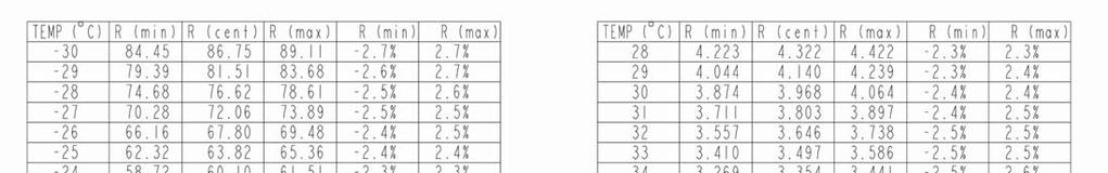
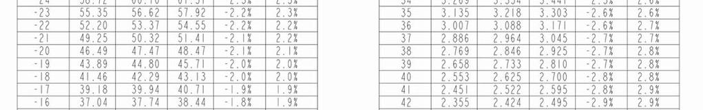
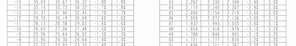
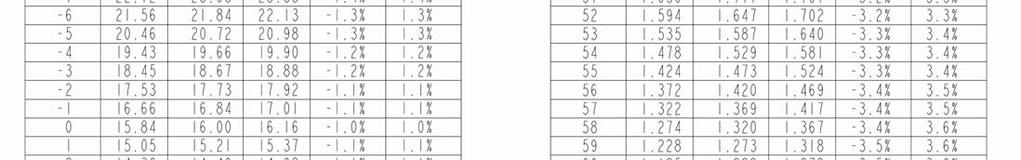
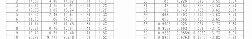
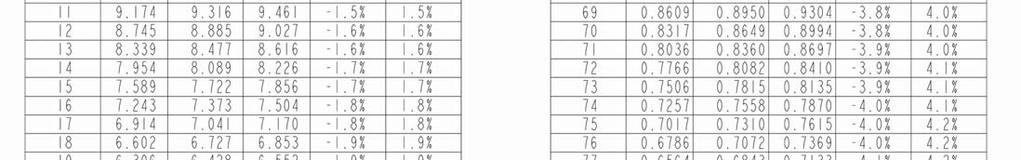
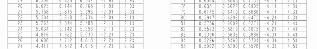
21 DISCHARGE SENSOR/AIR INLET SENSOR CHART 21
22 22

23 PIN OUT CHART 23
24 Wiring Diagram for Navistar Prior to 11/11/13 24
25 Wiring Diagram for Navistar Prior to 11/11/13 25
26 Wiring Diagram for Navistar After 11/11/2013 and prior to 6/23/
27 Wiring Diagram for Navistar After 11/11/2013 and prior to 6/23/
28 Wiring Diagram for Navistar as of 06/23/2014 * WIRING WITH REMOTE VOLTAGE SENSING WIRES ADDED (PINS A9 AND B9 ON MAIN 30-WAY CONNECTOR) 28
29 Wiring Diagram for Navistar as of 06/23/
SECOND GENERATION Use this guide with unit serial number prefix beginning with BWF using Terra Power separator.
 Technical Information and Diagnostic Guide for SECOND GENERATION Use this guide with unit serial number prefix beginning with BWF using Terra Power separator. This guide will assist you in becoming more
Third Generation NITE Phoenix
 Technical Information and Diagnostic Guide for Third Generation NITE Phoenix Use this guide with unit serial number prefix beginning with BYC, CAI built after 2-10-2012 and CCA, CDJ, CIA units after 6/25/2012
Technical Information and Diagnostic Guide
 Technical Information and Diagnostic Guide This guide will assist you in becoming more familiar with the working components of the NITE System and the proper steps and procedures to completely diagnose
Technical Information and Diagnostic Guide RestStar Use this guide with 5700XE RestStar Unit. Western Star 5700XE.
 Western Star 5700XE RestStar 4 10-2017 1 Technical Information and Diagnostic Guide RestStar Use this guide with 5700XE RestStar Unit 2390 Blackhawk Road P.O. Box 6007 Rockford, IL 61125 nitesystem.com
Technical Information and Diagnostic Guide for Freightliner ParkSmart Rev5/Split No Idle System for optimized idle - beginning March 2013
 Technical Information and Diagnostic Guide for Freightliner ParkSmart Rev5/Split No Idle System for optimized idle - beginning March 2013 Beginning 3/7/2016 all (NEW) trucks are built with the Optimized
A/C-HEATER SYSTEM - AUTOMATIC
 A/C-HEATER SYSTEM - AUTOMATIC 1988 Toyota Celica 1988 Automatic A/C-Heater Systems Celica * PLEASE READ THIS FIRST * CAUTION: When discharging air conditioning system, use only approved refrigerant recovery/recycling
ARTICLE BEGINNING * PLEASE READ THIS FIRST * DESCRIPTION OPERATION ATC COMPUTER BLEND-AIR DOOR ACTUATOR CONTROL PANEL
 A/C-HEATER SYSTEM - AUTOMATIC Article Text 1989 Chrysler LeBaron Sedan For m m m m m Copyright 1998 Mitchell Repair Information Company, LLC Thursday, July 03, 2003 10:15AM ARTICLE BEGINNING 1989 AUTOMATIC
A/C SYSTEM GENERAL DIAGNOSTIC PROCEDURES
 Article Text ARTICLE BEGINNING 1993 AIR CONDITIONING & HEAT A/C General Diagnostic Procedures Diagnosis is an important first step in A/C system servicing. To save time and effort, systems should be carefully
C.E. Niehoff & Co. C653/C653A and C625 Alternators Troubleshooting Guide NOTICE. Hazard Definitions. Battery Charge Volt and Amp Values
 C.E. Niehoff & Co. C653/C653A and C625 Alternators Troubleshooting Guide Hazard Definitions These terms are used to bring attention to presence of hazards of various risk levels or to important information
 Page 1 of 50 Section 412-00: Climate Control System General Information DIAGSIS AND TESTING 1997 Mark VIII Workshop Manual Climate Control System Special Service Tool(s) 73 Digital Multimeter 105-R0051
Modulating Furnace Information. Warning on Meter Setting - Read First!
 Modulating Furnace Information Pressure Transducer Pressure DC Volts 0.00" 0.25 0.20" 0.63 0.25" 0.72 0.30" 0.82 0.35" 0.91 0.40" 1.00 0.45" 1.09 0.50" 1.19 0.55" 1.28 0.60" 1.38 0.65" 1.47 0.70" 1.56
Electronic Refrigerator Diagnostics
 Electronic Refrigerator Diagnostics IMPORTANT SAFETY NOTICE The information in this presentation is intended for use by individuals possessing adequate backgrounds of electrical, electronic, & mechanical
EDITOR'S NOTE: This article replaces "Use PGM FI Data List to Help Troubleshoot Inoperative A/C," issued in June 2012.
 2001 Honda Civic 1.7L Eng LX TROUBLESHOOTING AN INOPERATIVE A/C TECHNICAL SERVICE BULLETIN Reference Number(s): 13 080J, Date of Issue: August, 2013 HONDA: '00 and later models with A/C APPLIES TO: '00
Sturdy Truck Body Poultry Shipping Truck - Operations Manual August 2003
 1.0 Introduction The Sturdy ventilation controller is designed to automatically control indoor air quality including: temperature, relative humidity, carbon dioxide and oxygen in the interior of the vehicle
Program IV: ProStar TM. Performance A/C International. Series. Study Guide Performance A/C Program IV: International ProStar Series TMT
 Performance A/C International A N AV I S TA R C O M PA N Y Program IV: ProStar TM Study Guide TMT-160701 Series Study Guide Performance A/C Program IV: International ProStar Series TMT-160701 2007 International
A/C-HEATER SYSTEM - AUTOMATIC
 A/C-HEATER SYSTEM - AUTOMATIC 1996 Subaru SVX 1995-96 AUTOMATIC A/C-HEATER SYSTEMS Subaru SVX * PLEASE READ THIS FIRST * WARNING: To avoid injury from accidental air bag deployment, read and carefully
C802/C802D/C802TD/C820 Alternators Troubleshooting Guide
 C802/C802D/C802TD/C820 Alternators Troubleshooting Guide Hazard Definitions These terms are used to bring attention to presence of hazards of various risk levels or to important information concerning
ENGINE COOLING FAN Toyota Celica ELECTRIC COOLING FAN RADIATOR COOLING FAN SYSTEM TEST ENGINE COOLING Toyota Engine Cooling Fans
 ENGINE COOLING FAN 1994 Toyota Celica 1994 ENGINE COOLING Toyota Engine Cooling Fans Celica 1.8L 4-Cyl ELECTRIC COOLING FAN NOTE: Electric cooling fan may be used for radiator or condenser. To verify electric
BRIVIS DUCTED INVERTER SERVICE MANUAL DRCi
 BRIVIS DUCTED INVERTER SERVICE MANUAL DRCi 1 TABLE OF CONTENTS TABLE OF CONTENTS... 2 IMPORTANT NOTE... 3 FAULT FINDING AND DIAGNOSTICS... 3 ABBREVIATIONS... 3 PCB S... 4 OUTDOOR MAIN PCB... 4 INDOOR PCB...
User s Manual. Automatic Switch-Mode Battery Charger
 User s Manual Automatic Switch-Mode Battery Charger IMPORTANT Read, understand, and follow these safety rules and operating instructions before using this battery charger. Only authorized and trained service
SECTION Climate Control System - General Information
 412-00-i Climate Control System - General Information 412-00-i SECTION 412-00 Climate Control System - General Information CONTENTS PAGE DIAGNOSIS AND TESTING Climate Control System... 412-00-2 Inspection
ELECTRICAL SYSTEM RP-7
 ELECTRICAL SYSTEM RP-7 This section of the manual does not include integral electrical components of the engine. Refer to section Engine RP-1 for details. This section of the manual is divided into three
DIAGNOSIS AND TESTING
 412-00-1 Climate Control System - General Information 412-00-1 DIAGNOSIS AND TESTING Climate Control System Refer to Wiring Diagrams Cell 54, Air Conditioning/Heater for schematic and connector information.
1. DO NOT HANDLE REFRIGERANT IN AN ENCLOSED AREA OR NEAR AN OPEN FLAME
 2006 Toyota 4Runner 4.0L Eng Limited 1Search AIR CONDITIONER REQUESTED INFORMATION PRECAUTION 1. DO NOT HANDLE REFRIGERANT IN AN ENCLOSED AREA OR NEAR AN OPEN FLAME 2. ALWAYS WEAR EYE PROTECTION Fig 1:
TABLE OF CONTENTS INTRODUCTION.. 3. A/C Ducting Installation. Power Kit Installation (Batteries)...5 OPERATION MANUAL 7-8 TOOLS LIST..
...5 OPERATION MANUAL 7-8 TOOLS LIST..") 585457 1 TABLE OF CONTENTS SECTION PAGE INTRODUCTION.. 3 INSTALLATION PROCEDURES Air Conditioner Location...4 Air Conditioner Mounting 4 A/C Ducting Installation...5 Power Kit Installation (Batteries)...5
585457 1 TABLE OF CONTENTS SECTION PAGE INTRODUCTION.. 3 INSTALLATION PROCEDURES Air Conditioner Location...4 Air Conditioner Mounting 4 A/C Ducting Installation...5 Power Kit Installation (Batteries)...5
Jeep Wrangler TJ 4.0 LITER Installation instructions
 www.jeepair.com 2000-2001 Jeep Wrangler TJ 4.0 LITER Installation instructions Important information about your system, and warranty DO NOT ADD ANY OIL TO ANY PART OF THE SYSTEM. DO NOT USE THE SIGHT GLASS
STANDARD AND GROUND SWITCHED APPLICATIONS
 SNOWDOGG LIGHT REFERENCE STANDARD AND GROUND SWITCHED APPLICATIONS GENERAL REFERENCE SNOWDOGG LIGHT REFERENCE GENERAL REFERENCE 3 TROUBLESHOOTING GUIDES/PROCEDURES 6 CONNECTOR REFERENCE 12 ADAPTER HARNESS
 Page 1 of 54 412-00 Climate Control System General Information and Diagnostics 2006 Crown Victoria/Grand Marquis DIAGNOSIS AND TESTING Procedure revision date: 12/23/2008 Climate Control System Printable
Subject Underhood G System Error Codes and Symptoms System or Parts affected
 System or Parts affected Index Underhood70G (V90Gxxx) System or Parts affected... 1 Overview... 1 Identifying your System... 1 Retrieving Logged Error Messages... 1 Error Messages... 3 Error Message Table...
INSTRUMENT PANEL AND GAUGES INSTRUMENT PANEL AND GAUGES XJ
 J INSTRUMENT PANEL AND GAUGES 8E - 1 INSTRUMENT PANEL AND GAUGES GROUP INDEX INSTRUMENT PANEL AND GAUGES XJ... 1 INSTRUMENT PANEL AND GAUGES YJ... 24 INSTRUMENT PANEL AND GAUGES XJ CONTENTS page DIAGNOSIS...
Idle Free Systems, Inc. Reference Guide System Component Information
 Idle Free Systems, Inc. Reference Guide System Component Information #68004 REV 3 #68004 REV 3 Idle Free Reference Sheets System Components & Trouble shooting Table of Contents RF # 101.0 102.0 103.0 104.0
SERVICE & OWNER S MANUAL
 1 of 10 SERVICE & OWNER S MANUAL Product Specifications 25 x 36 x 7 Weight: 47 lbs. Air Flow: 260 CFM Air Conditioner p/n: 1ACUNIT-G1 Fits with Curtis Roof Kit: Contact Curtis for Details. Fits with Curtis
 Page 1 of 29 Section 04-05: Suspension, Computer Controlled 1997 Town Car Workshop Manual DIAGNOSIS AND TESTING Procedure revision date: 05/16/2000 Suspension, Computer Controlled Inspection and Verification
6500DC Dual Motor Wireless Controller Kits
 6500DC Dual Motor Wireless Controller Kits READ ALL DIRECTIONS FIRST BEFORE PROCEEDING NOTE: SEE THE QUICK PROGRAM INSTRUCTIONS BEFORE OPERATING THE FIRST TIME. DO NOT REMOVE THE TRANSMITTER BATTERY Please
STARTING SYSTEMS 8B - 1 STARTING SYSTEMS CONTENTS
 TJ STARTING SYSTEMS 8B - 1 STARTING SYSTEMS CONTENTS page DESCRIPTION AND OPERATION STARTER MOTOR... 2 STARTER RELAY... 3 STARTING SYSTEM... 1 DIAGNOSIS AND TESTING STARTER MOTOR... 8 STARTER MOTOR NOISE
A/C-HEATER SYSTEM - AUTOMATIC
 A/C-HEATER SYSTEM - AUTOMATIC 1993 Toyota Celica 1993 Automatic A/C-Heater Systems Celica SPECIFICATIONS SPECIFICATIONS TABLE Application Specification Compressor Type 1.6L... Nippondenso 10PA15C 10-Cyl.
CHARGING SYSTEM 8C - 1 CHARGING SYSTEM CONTENTS
 ZG CHARGING SYSTEM 8C - 1 CHARGING SYSTEM CONTENTS page GENERAL INFORMATION OVERVIEW... 1 DESCRIPTION AND OPERATION BATTERY TEMPERATURE SENSOR... 2 CHARGING SYSTEM OPERATION... 1 ELECTRONIC VOLTAGE REGULATOR...
Troubleshooting Guide
 Troubleshooting Guide diesel - gasoline - LPG diesel - gasoline - LPG diesel - gasoline - LPG P/N 0191681 May, 1999 An ISO 9001 Registered Company P.O. Box 1160 St. Joseph, MO 64502-1160 1-800-255-0317
TABLE OF CONTENTS INTRODUCTION 3. INSTALLATION PROCEDURES Air Conditioner Location 4. A/C Ducting Installation 5
 585474 1 TABLE OF CONTENTS SECTION PAGE INTRODUCTION 3 INSTALLATION PROCEDURES Air Conditioner Location 4 Air Conditioner Mounting 4 A/C Ducting Installation 5 Power Kit Installation (Batteries). 5 Separator...
Phoenix Service Parts NITE Tech Support Line nitesystem.com
 Product Description 1 Phoenix 1000224398 Obsolete x x If you are replacing a SRT or BWF unit with a CSG Built after Service Unit 6/26/17 you will need to upgrade to a Phoenix Retro Kit 1001697266 ( 3699045)
A/C SYSTEM SPECIFICATIONS
 A/C SYSTEM SPECIFICATIONS SPECIFICATIONS Application Specification Compressor Type Matsushita Matsushita Rotary Sanden Sanden Scroll Compressor Belt Deflection (1) Used 5/16-7/16" (8-9.5 mm) New 9/32-5/16"
DESCRIPTION AND OPERATION
 Page 1 of 10 DESCRIPTION AND OPERATION AIR DELIVERY DESCRIPTION AND OPERATION The air delivery description and operation is divided into five areas: HVAC Control Components Air Speed Air Delivery Recirculation
ARC4000e 4 wheel compressor system w / 4 way Ride Pro controller
 350 S. St. Charles St. Jasper, In. 47546 Ph. 812.482.2932 Fax 812.634.6632 on the internet: www.ridetech.com ARC4000e 4 wheel compressor system w / 4 way Ride Pro controller 1 ARC5001 Compressor 1 CON6000
STANDARD OWNER S MANUAL
 WILLIE 1.0 STANDARD OWNER S MANUAL OPERATION, MAINTENANCE, & TROUBLESHOOTING STANDARD INSTRUCTIONS FOR ALL SYSTEMS DSE 3100 4/28/2011 Willis Power Systems 2950 N Martin Springfield, MO 65803 417.831.2520
2003 Explorer/Mountaineer Workshop Manual
 Page 1 of 11 SECTION 414-00: Battery and Charging System 2003 Explorer/Mountaineer Workshop Manual DIAGNOSIS AND TESTING Procedure revision date: 06/18/2002 Charging System Printable View (257 KB) Refer
Troubleshooting Guide
 Troubleshooting Guide P/N 0153180 July 1999 P.O. Box 1160 St. Joseph, MO 64502-1160 1-800-255-0317 Fax: 816-360-9379 www.snorkelusa.com GENERAL INFORMATION This manual contains procedures for locating
CONTROLLER DIAGNOSTIC GUIDE
 Proprietary tice: This document contains proprietary information which not to be reproduced, transferred, to other documents, disclosed to others, used for manufacturing or any other purpose without the
3 in 1 TRAIL CHARGER with LOCKOUT
 Owner s Manual P/N: 283821 500 3 in 1 TRAIL CHARGER with LOCKOUT 283821 01 Version 2.04 07/05/2011 Owners Manual Operation Installation Wiring Diagram Troubleshooting Parts Breakdown 1 GENERAL OPERATION
HP21 SERVICE SUPPLEMENT UNIT INFORMATION. TSC6 Two-Speed Control
 SERVICE UNIT INFORMATION SUPPLEMENT HP21 Corp. 9426 L10 Litho U.S.A. All HP21-4 and -5 units (single and three phase) are equipped with a TSC6 two-speed control. The TSC6 (A14) two-speed control contains
Series 1000 and Figure NOTE: The top terminals are showing normally closed at rest and the middle terminals are normally
 38.18.The red wire on the OCR plug carries battery voltage. Behavior: D.C. battery voltage should show-up on a volt meter when the red probe is touched to this terminal and the black probe is grounded,
2001 Dodge Caravan Sport MANUAL A/C-HEATER SYSTEMS Caravan, Town & Country, & Voyager
 SPECIFICATIONS NOTE: Information for Caravan includes the Grand Caravan. SPECIFICATIONS Application Specification Compressor Type Nippondenso 10S20H Compressor Belt Tension (1) System Oil Capacity (2)
DIAGNOSIS AND TESTING
 412-00-1 Climate Control System - General Information 412-00-1 DIAGNOSIS AND TESTING Climate Control System Refer to Wiring Diagrams Cell 54, Air Conditioner/Heater for schematic and connector information.
An ISO 9001:2008 Registered Company
 An ISO 9001:2008 Registered Company CVC501-A HVAC & Fast Idle CAN Vehicle Controller CVC502-A HVAC Control without Fast Idle 2011-2016 Ford F250-F550 (CVC501/502-A) 2017 Ford F-250-F550 (B-CVC501/502-A)
N1233 Series Troubleshooting Guide for N Alternator
 N1233 Series Troubleshooting Guide for N1233-2 Alternator Hazard Definitions These terms are used to bring attention to presence of hazards of various risk levels or to important information concerning
C.E. Niehoff & Co. N1601, N1602, N1603, and N1604 Alternator Troubleshooting Guide NOTICE. Hazard Definitions. Battery Charge Volt and Amp Values
 C.E. Niehoff & Co. N1601, N1602, N1603, and N1604 Alternator Troubleshooting Guide Hazard Definitions These terms are used to bring attention to presence of hazard(s) of various risk levels or to important
Battery Control Center - Diesel
 Service Manual CAUTION: All servicing of the Battery Control Center should be done only by a qualified Service Technician. Inadvertent shorts inside the Battery Control Center could result in severe damage
AIR CONDITIONING BLOWER CONTROL MODULE/BLOWER RESISTOR TEST G - BLOWER MOTOR OPERATES AT HIGH SPEED AT ALL SPEED SETTINGS
 1996 Ford Taurus 3.0L Eng LX AIR CONDITIONING BLOWER CONTROL MODULE/BLOWER RESISTOR TEST G - BLOWER MOTOR OPERATES AT HIGH SPEED AT ALL SPEED SETTINGS 1. Check Blower Operation Disconnect RCC module harness
Section 6. Electrical System
 Section 6 Electrical System Introduction. This machine incorporates a 12-volt DC electrical system. Optional equipment selected by the customer will determine the electrical equipment to be installed in
AUTOMATIC AIR CONDITIONER > COMPONENT DIAGNOSIS > BLOWER MOTOR CONTROL SYSTEM > SYSTEM DESCRIPTION > SYSTEM DESCRIPTION
 2008 Nissan Armada 5.6L Eng SE HEATER & AIR CONDITIONING CONTROL SYSTEM MOTOR CONTROL SYSTEM > SYSTEM DESCRIPTION > SYSTEM DESCRIPTION Component Parts Blower speed control system components are: A/C auto
English - Español - Français - Deutsch - Italiano
 English - Español - Français - Deutsch - Italiano INTRODUCTION Thank you for purchasing Power Probe products. The Power Probe is the best professional electrical tester for reducing diagnostic time in
EXTERNAL CONTROL VALVE (ECV) EQUIPPED VARIABLE A/C COMPRESSOR DIAGNOSIS PROCEDURE
 EQUIPPED VARIABLE A/C COMPRESSOR DIAGNOSIS PROCEDURE") Technical Service Bulletin GROUP DATE HVAC JUNE, 2017 NUMBER MODEL(S) 17-HA-002 Multiple Models EXTERNAL CONTROL VALVE (ECV) EQUIPPED VARIABLE A/C COMPRESSOR DIAGNOSIS PROCEDURE This bulletin supersedes
Technical Service Bulletin GROUP DATE HVAC JUNE, 2017 NUMBER MODEL(S) 17-HA-002 Multiple Models EXTERNAL CONTROL VALVE (ECV) EQUIPPED VARIABLE A/C COMPRESSOR DIAGNOSIS PROCEDURE This bulletin supersedes
37. FATC (FULL AUTO TEMP. CONTROL) CIRCUIT 6810
 CIRCUIT 6810") 5156 6810 37. FATC (FULL AUTO TEMP. CONTROL) CIRCUIT 6810 1) CONDENSOR FAN, AIR MIX MOTOR, SUN SENSOR, WATER TEMP SENSOR A. CONNECTOR INFORMATION 6810 5157 Connector Number (Pin Number, Color) Connecting
5156 6810 37. FATC (FULL AUTO TEMP. CONTROL) CIRCUIT 6810 1) CONDENSOR FAN, AIR MIX MOTOR, SUN SENSOR, WATER TEMP SENSOR A. CONNECTOR INFORMATION 6810 5157 Connector Number (Pin Number, Color) Connecting
N1240/N1243 Series Troubleshooting Guide for N1240-3/N Alternators
 N1240/N1243 Series Troubleshooting Guide for N1240-3/N1243-2 Alternators Hazard Definitions These terms are used to bring attention to presence of hazards of various risk levels or to important information
ZIP Economizer Fault Detection and Diagnostics (FDD) Table
 Table") Fault Detection and Diagnostics (FDD) Table Fault Detection Problem Diagnostic ction (in addition to alarm stored / transmitted) Potential Cause C Fault Code OT sensor predetermined range O damper returns
Fault Detection and Diagnostics (FDD) Table Fault Detection Problem Diagnostic ction (in addition to alarm stored / transmitted) Potential Cause C Fault Code OT sensor predetermined range O damper returns
Power Distribution System User s Manual. Model: PDS-100
 Power Distribution System User s Manual Model: PDS-0 Section Page Product Overview... 1 I) General Information... 2 II) Important Safety Information... 2 III) Installation... 3 A) Materials Provided...
MANUAL CONTROL / SEMIAUTO TEMPERATURE CONTROL HEATING, VENTILATION AND AIR CONDITIONING SYSTEM
 SECTION 7C MANUAL CONTROL / SEMIAUTO TEMPERATURE CONTROL HEATING, VENTILATION AND AIR CONDITIONING SYSTEM CAUTION: Disconnect the negative battery cable before removing or installing any electrical unit
WPS-104 Heater Installation Instructions For 500EFI, 700 XP, & Crew Applications
 WPS-104 Heater Installation Instructions For 500EFI, 700 XP, & Crew Applications ORDER OF INSTALLATION FOR A COMPLETE ENCLOSURE OF A RANGERWARE WPS (Weather Protection System) IS AS FOLLOWS: 1. Heater
AIR CONDITIONER SECTION AC CONTENTS AUTO
 AIR CONDITIONER SECTION AC CONTENTS AUTO PRECAUTIONS AND PREPARATION SRS Airbag Pretensioner Seatbelt... 4 A/C Refrigerant HFC134a Handling... 4 Compressor Oil... 4 Tube Connection... 4 O-Ring Part Number...
JLK-019. Jaguar Dealer. After renewing a fuse have the circuit checked by
 4-12 Roadside emergency service s and Boxes failure is signalled by an inoperative circuit. Do not fit a new fuse if damage to the wiring is found; contact a Jaguar Dealer. After renewing a fuse have the
eapu Reference Guide System Component Information (For serial numbers starting with 37)
") eapu Reference Guide System Component Information (For serial numbers starting with 37) #68004 REV B December 2018 Table of Contents Topic Battery Separator 3 DC Voltage 6 Thermostat 7 Power Converter
eapu Reference Guide System Component Information (For serial numbers starting with 37) #68004 REV B December 2018 Table of Contents Topic Battery Separator 3 DC Voltage 6 Thermostat 7 Power Converter
ADVANCED PID TROUBLESHOOTING
 ADVANCED PID TROUBLESHOOTING August 29, 2016 A KEY POINT If the drive is telling you something via a Fault, then the problem is probably not the drive. The drive is recognizing a fault and telling you
Computers and Control Systems: Symptom Related Diagnostic Procedures C Charts. Part 1 of 6. Chart C-1 (1 Of 6)
") 1993 Cadillac DeVille V8-300 4.9L Page 1 Computers and Control Systems: Symptom Related Diagnostic Procedures C Charts Part 1 of 6 Chart C-1 (1 Of 6) 1993 Cadillac DeVille V8-300 4.9L Page 2 Wiring Diagram.
1993 Cadillac DeVille V8-300 4.9L Page 1 Computers and Control Systems: Symptom Related Diagnostic Procedures C Charts Part 1 of 6 Chart C-1 (1 Of 6) 1993 Cadillac DeVille V8-300 4.9L Page 2 Wiring Diagram.
PERFECT FIT IN-DASH HEAT/ COOL/ DEFROST FORD FAIRLANE & CROWN VICTORIA
 PERFECT FIT IN-DASH HEAT/ COOL/ DEFROST 1955-56 FORD FAIRLANE & CROWN VICTORIA CONTROL & OPERATING INSTRUCTIONS The controls on your new Perfect Fit system, offer complete comfort capabilities in virtually
& 76 CHEVROLET NOVA HEATER ONLY
 specializing in AIR CONDITIONING, PARTS AND SYSTEMS for your classic hi l PERFECT FIT IN-DASH HEAT/ COOL/ DEFROST 1969-74 & 76 CHEVROLET NOVA HEATER ONLY CONTROL & OPERATING INSTRUCTIONS The controls on
Users Manual. Defender 1 8.0KW to 14.0KW Online Emergency Lighting Inverter. Technical Manual # Revision B
 Users Manual Defender 1 8.0KW to 14.0KW Online Lighting Inverter Technical Manual #018-0102-01 Revision B Phone: 1.877.DSPM.POWER 1.877.377.6769 Fax: 909.930.3335 Website: www.dspmanufacturing.com E-Mail:
Different oils are used in automotive A/C systems, based on the type of refrigerant. Polyalkylene Glycol (PAG) oil is used for R-134a refrigerant.
 oil is used for R-134a refrigerant.") Lubricants Automotive air conditioning lubricants are specially formulated because of how and where they operate. Air conditioning oils must be dry (having little or no water content) and mix with the
Lubricants Automotive air conditioning lubricants are specially formulated because of how and where they operate. Air conditioning oils must be dry (having little or no water content) and mix with the
Fault Code 34 - Weak Battery Voltage Supply
 Fault Code 34 - Weak Battery Voltage Supply Fault Isolation Procedures TRTS0930 Fault Code 34 - Weak Battery Voltage Supply J1587: MID 130 PID 168 FMI 14 J1939: SA 3 SPN 168 FMI 14 Overview This fault
1998 INDEX Sensors & Controls, Inc. All Rights Reserved
 ACPU CM-820 APAds ACPU Controller Product Description and Troubleshooting Manual 1998 INDEX Sensors & Controls, Inc. All Rights Reserved The information contained herein is proprietary data, and is not
Users Manual. Cobra Plus Stand-By Emergency Lighting Inverter. Technical Manual # Revision B
 Users Manual Cobra Plus Stand-By Lighting Inverter Technical Manual #018-0110-01 Revision B Phone: 1.877.DSPM.POWER 1.877.377.6769 Fax: 909.930.3335 Website: www.dspmanufacturing.com E-Mail: techsupport@dspmanufacturing.com
Installation Manual #
 Final 10/01/08 Installation Manual # 585416 T600, T800 and W900 Bergstrom, Inc. 2390 Blackhawk Road P.O. Box 6007 Rockford, IL 61125 www.nitesystem.com 1-866-204-8570 Table of Contents Introduction Before
TC Series Cooling Systems
 TC Series Cooling Systems Table of Contents Table of Contents...1 List of Figures...1 Safety...2 Introduction...2 General Specifications...2 Types of Coolant...2 Routine Maintenance...2 Surge Tank Coolant
SERIES 700/700E FACTORY KEYLESS UPGRADE INSTALLATION MANUAL
 SERIES 700/700E FACTORY KEYLESS UPGRADE INSTALLATION MANUAL Items Supplied with the System: Installation Instructions: Main unit 1. Mounting the module: Plug In LED Mount the module in a suitable location
INSTALLATION INSTRUCTIONS
 INSTALLATION INSTRUCTIONS Universal Air Series!! NOTE!! Covers the following model: 6000 Series 85-0100B-AZ Rev 0 5/07 To ensure that the system is installed properly, provide your electrician with these
Troubleshooting Guide
 Troubleshooting Guide diesel - gasoline - LPG P/N 0172021 June 1999 P.O. Box 1160 St. Joseph, MO 64502-1160 1-800-255-0317 Fax: 816-360-9379 www.snorkelusa.com GENERAL INFORMATION This manual contains
WARNING This manual should only be used by a qualified Service Technician. FinishPro 390/395 Airless/Air-Assisted Sprayer Repair Electrical Manual
 FinishPro 390/395 Airless/AirAssisted Sprayer Repair Electrical Manual First choice when quality counts. Rev. B 10/11 /07 FinishPro 395 3.00 ti9026a Red Yel Yel Air Hose Connection FinishPro 390 Exhaust
MD10. Engine Controller. Installation and User Manual for the MD10 Engine Controller. Full Version
 MD10 Engine Controller Installation and User Manual for the MD10 Engine Controller. Full Version File: MartinMD10rev1.4.doc May 16, 2002 2 READ MANUAL BEFORE INSTALLING UNIT Receipt of shipment and warranty
2002 Ford Explorer STARTING & CHARGING SYSTEMS' 'Generators & Regulators - Explorer & Mountaineer STARTING & CHARGING SYSTEMS
 DESCRIPTION 2002-03 STARTING & CHARGING SYSTEMS Generators & Regulators - Explorer & Mountaineer System consists of generator, regulator, battery, fuses, PCM and associated wiring. Generators have an electronic
Operator s Manual. TriPac EVOLUTION Diesel Particulate Filter (DPF) TK OP (Rev. 2, 03/16)
 TK OP (Rev. 2, 03/16)") Operator s Manual TriPac EVOLUTION Diesel Particulate Filter (DPF) TK 56295-19-OP (Rev. 2, 03/16) TriPac EVOLUTION with Diesel Particulate Filter (DPF) TK 56295-19-OP (Rev. 2, 03/16 Copyright 2013 Thermo
Operator s Manual TriPac EVOLUTION Diesel Particulate Filter (DPF) TK 56295-19-OP (Rev. 2, 03/16) TriPac EVOLUTION with Diesel Particulate Filter (DPF) TK 56295-19-OP (Rev. 2, 03/16 Copyright 2013 Thermo
Service Manual for Battery Control Center
 Service Manual for Battery Control Center P/N 82 E0071 00 (Ref. 81 1317) June, 1999 Battery Control Box Operation Charging Circuit This function charges the coach battery from the engine alternator while
HEATING & AIR CONDITIONING
 VA HEATING & AIR CONDITIONING 24-1 HEATING & AIR CONDITIONING TABLE OF CONTENTS page HEATING & AIR CONDITIONING DESCRIPTION...1 OPERATION...2 DIAGNOSIS AND TESTING A/C PERFORMANCE...3 HEATER PERFORMANCE
PERFECT FIT SERIES IN-DASH HEAT/ COOL/ DEFROST MUSTANG
 specializing in AIR CONDITIONING, PARTS AND SYSTEMS for your classic vehicle PERFECT FIT SERIES IN-DASH HEAT/ COOL/ DEFROST 1969-70 MUSTANG CONTROL & OPERATING INSTRUCTIONS The controls on your new Perfect
TECHNICAL SERVICE DEPARTMENT Technical Service Bulletin LowNOx Commercial Gas Electronic Spark Ignition Sequence
 The Universal TM gas LowNOx series water heaters contain an electronic spark ignition system. The heater is connected to a 120VAC power source required by the transformer. The transformer steps down the
an ISO 9001:2008 Registered Company 1964 CHEVY IMPALA WITHOUT FACTORY AIR REV C 7/8/14, 1964 IMPALA wo AC EVAP INST PG 1 OF 25
 an ISO 9001:2008 Registered Company 1964 CHEVY IMPALA WITHOUT FACTORY AIR 561064 903061 REV C 7/8/14, 1964 IMPALA wo AC EVAP INST PG 1 OF 25 903061 REV C 7/8/14, 1964 IMPALA wo AC EVAP INST PG 2 OF 25
ALTERNATOR REQUESTED INFORMATION. Vehicles With Dual Generator [ Engine Mount - LH ] 2007 Ford Pickup 6.0L Eng F350 Super Duty
![ALTERNATOR REQUESTED INFORMATION. Vehicles With Dual Generator [ Engine Mount - LH ] 2007 Ford Pickup 6.0L Eng F350 Super Duty](/thumbs/72/66590437.jpg "ALTERNATOR REQUESTED INFORMATION. Vehicles With Dual Generator [ Engine Mount - LH ] 2007 Ford Pickup 6.0L Eng F350 Super Duty") ALTERNATOR 2007 Ford Pickup 6.0L Eng F350 Super Duty REQUESTED INFORMATION Vehicles With Dual Generator [ Engine Mount - LH ] Fig 1: Rotating Drive Belt Tensioner Clockwise 1. Remove the accessory drive
ALTERNATOR 2007 Ford Pickup 6.0L Eng F350 Super Duty REQUESTED INFORMATION Vehicles With Dual Generator [ Engine Mount - LH ] Fig 1: Rotating Drive Belt Tensioner Clockwise 1. Remove the accessory drive
Terex Utilities. Issue: Action:
 Terex Utilities PRODUCT ADVISORY PA-1024-14 DATE: 7/21/14 REVISED: TO: Owners, Users, Dealers, and Installers Models Affected: Units with a 408V HyPower TM System Installed SUBJECT: 408V HyPower TM Systems
Installation Manual #
 FINAL 10/06/08 Installation Manual #1000067001 Cascadia Under Bunk Mounting Bergstrom, Inc. 2390 Blackhawk Road P.O. Box 6007 Rockford, IL 61125 www.nitesystem.com 1-866-204-8570 Table of Contents Introduction
2002 ENGINE PERFORMANCE. Self-Diagnostics - RAV4. Before performing testing procedures, check for any related Technical Service Bulletins (TSBs).
.") 2002 ENGINE PERFORMANCE Self-Diagnostics - RAV4 INTRODUCTION NOTE: Before performing testing procedures, check for any related Technical Service Bulletins (TSBs). To properly diagnosis and repair this
2002 ENGINE PERFORMANCE Self-Diagnostics - RAV4 INTRODUCTION NOTE: Before performing testing procedures, check for any related Technical Service Bulletins (TSBs). To properly diagnosis and repair this
6000DC Single 12V Motor Wireless Controller Kits With Extra Options
 6000DC Single 12V Motor Wireless Controller Kits With Extra Options READ ALL DIRECTIONS FIRST BEFORE PROCEEDING NOTE: SEE THE QUICK PROGRAM INSTRUCTIONS BEFORE OPERATING THE FIRST TIME. DO NOT REMOVE THE
Northwest RV Supply Manual Compliments of Printed From TROUBLESHOOTING
 TROUBLESHOOTING for the 5 BUTTON 3109228.001 COMFORT CONTROL CENTER SYSTEM INTRODUCTION The Comfort Control Center control system can be used to operate the following Duo-Therm Units: Roof Top Air Conditioners
Troubleshooting Guide
 Troubleshooting Guide RV-C System Layout BCM Pin Values Tanks Interior Lighting I/O Exterior Lighting I/O Pin Name BCM Function Note A DMM 1 Fresh 1 Tank In Input from Sending Unit 2 Fresh 2 Tank In Input