Flexible power and control cables
|
|
|
- Beverley Malone
- 6 years ago
- Views:
Transcription

1 Flexible power and control cables PROAD029 distributed by the Cavotec Group
2 Flexible power cables Flexible control cables The Cavotec Group Cavotec is the name of a group of companies specialized in power supply technology for cranes and other industrial equipment. It is formed by 5 manufacturing "Centres of Excellence" located in Canada, France, Germany, Italy and Sweden and by 5 local manufacturing units located in Australia, China, Germany, Sweden and USA. For distribution of their products and support to customers Cavotec has 22 sales companies which, together with a network of Distributors, serve more than 30 countries on five continents. Each manufacturing company, no matter where it is located, aims at being a market leader in its field by providing innovative and reliable products to Group customers. Although they manufacture different products in different countries, they are globally supported and coordinated by the Cavotec Group in their product development and marketing activities. Each sales company, and each distributor, has a policy aiming at better serving its local market with the full support of the Cavotec Group. Our aim is to be local everywhere Great emphasis is put in providing the highest quality not only in the selected products, but also in service and backing to their customers. Our philosophy in fact is to be local everywhere. Our fields of activity are Mining, tunnelling Steel Mills Airports Ports, Terminals Robots, Automation Our competence is power supply technology To be able to offer a comprehensive selection of high quality cables to our customers, the Cavotec Group decided to select specialised manufacturing partners sharing our philosophy concerning the quality level and the service to the customer. Concerning flexible cables our Group cooperates with partners like Amercable, Baude, Gore, Palazzo, Pirelli and Nexans. The range of cables sold and serviced includes control cables, power cables, fiber optic cables and Kevlar reinforced cables for high stress applications. Offshore Constructions 2
 - reinforced 15 Basketheavyflex 16 CraneMAX control cable 17 Goreflex 18 Semoflex 19 Buflex-TP 20 H07 RN-F 21 Medium Voltage Panzerflex -L 23 Panzerflex -L FO 24 Panzerflat 25")
3 Table of contents How to choose the right cable for the job 4 Low Voltage Panzerflex 1kV low voltage power cable 11 Panzerflex 1kV low voltage control cable 12 Panzerflex VS 13 Panzerlite 14 Cordaflex (SMK) - reinforced 15 Basketheavyflex 16 CraneMAX control cable 17 Goreflex 18 Semoflex 19 Buflex-TP 20 H07 RN-F 21 Medium Voltage Panzerflex -L 23 Panzerflex -L FO 24 Panzerflat 25 Protolon (SMK) 26 Protolon (SMK) LWL 27 CraneMAX power cable 28 CraneMAX power cable-fo 29 Comparison between metric cross-section and AWG numbers 31 PBELT022 3

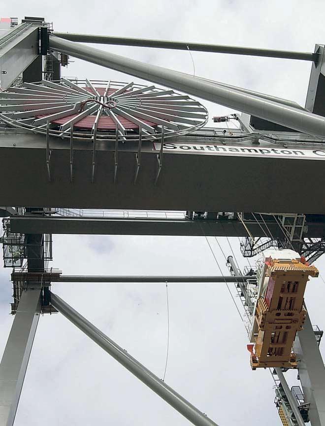
4 How to choose the right cable for the job. To illustrate possible questions that arise from using cables in different types of applications we have included below a case study from Palazzo Pirelli. This study is based completely on their technical calculations and experience and is not automatically applicable to other types or brands of cable. In order to be sure of the latest information and any possible changes always contact your cable manufacturer. CABLE003 A large, high speed Cavotec Specimas cable reel mounted on a coil handler running at 180 m/minute. Bending is not the only stress present with cables used for heavy duty applications. Mobile cables are subject to other stresses and strains (tensile, twisting etc.) resulting from forced guidance of the cable during the winding and unwinding phases. Consequently the correct choice is vital to ensure a long life of the cable. Naturally other factors of primary importance must also be taken into consideration. These are: Minimum bending radius Tensile stress Operating speed & acceleration Installation height & length Ambient Temperature The following paragraphs provide a detailed examination of these factors for accurate assessment of cable requirements. Main use Table 1: Palazzo type selection Suitable Not suitable TYPE OF CABLE TYPE OF CABLE APPLICATION Festoons Cable winding reels Cable tender systems Guide pulley system Pendant push buttons Cable chains Baskets with guide Cable laid on ground or in conduit Vertical cable Operating speed (m/min.max)* PANZERFLEX PANZERFLEX - FO (minimum temp C) PANZERFLEX - K (minimum temp C) PANZERFLEX - VS (minimum temp C) BASKETHEAVYFLEX (minimum temp C) Table
5 Bending radius and overall diameters Precise calculation of the bending radius is a determining factor for cable reliability. A decrease in minimum bending radius has a major effect on the life of a cable because it causes stretching and internal distortions. Another important factor is the frequency of the cable movements. If movement is slow and infrequent a tighter bending radius can be considered. Special attention should be taken for installations with pulleys or guide-rollers. Special attention should also be paid to installations where flexing and torsion is present due to the reels being parallel to the line of travel of the machine (see table 2). Tensile strength The maximum admissible continuous operating load is calculated by taking the sum of the cross sections of the power conductors (phases + earth of equal cross section) in the cable*. Greater loads will result in permanent elongation of the conductors, which would shorten the life of the cable considerably. For occasional or very infrequent stresses the calculated limit can be exceeded slightly. For control cables, where the resistant Table 2: Minimum bending radius OPERATING VOLTAGE Overall diameter of cable DE Fixed installation Anchoring reel cross section consists of numerous small conductors, special types of cables are available. In special cases, where the pulling strength exceeds the resistance of the conductors, cables are used fitted with strainers or other means such as Kevlar reinforcement. Operating speed All cables in this catalogue have been designed, manufactured and tested for the operating speeds commonly in use today. Of course these speeds are only possible if the recommendations made concerning the choice of cable have been observed. Please note that high acceleration in combination with high operating speeds should be taken into account when calculating the tensile stress in the cable. Coiling on cable reels Monospiral reels When using this type of reel the natural tendency of the cable is utilised. Alternatively it is also often possible to position the reel in order to eliminate the use of intermediate pulleys and any changes of direction. This increases the life of the cable and the operating speeds considerably. Festoons TYPE OF APPLICATION Cable reels Baskets Multi-spiral and multi-layer reels These types of reels are normally used in cases of long cable length and large diameter cables. With this type of installation, attention must be paid to minimising the use of intermediate pulleys. The current capacity must also be carefully calculated using correction factors for layers and winding. Spreader cables Some cables have specially designed to be collected in baskets. With these types of applications a correct design is not only important for good cable treatment but also to avoid operating malfunctions. High stress applications will typically involve long vertical lengths, high speeds combined with lateral movement and a presence of strong winds (typical port conditions). In these cases attention should be paid to ensure that the coiling diameter is no less than 1.5 mtr. and that a guide cone is located in the basket for even coiling of the cable. The shape of the basket and the size and shape of the opening are also important factors. A conical opening at a minimum height of 2 mtr. is recommended. Periodic lubrication of the surface of the cable is necessary to facilitate entry into the basket. Lubricating products that do not cause excessive accumulation of dirt should be used (figure 1 - page 6). Cable chains Cable tender systems Guide pulley systems Voltage 1000 V DE < 8.0 mm 3 x DE 3 x DE 5 x DE 4 x DE 7,5 x DE DE < 12.0 mm 3 x DE 4 x DE 5 x DE 4 x DE 7,5 x DE DE 20.0 mm 4 x DE 5 x DE 5 x DE 5 x DE 7,5 x DE DE > 20.0 mm 4 x DE 5 x DE 6 x DE 15 x DE 5 x DE 7,5 x DE Voltage > 1000 V 6 x DE 10 x DE 12 x DE 10 x DE 15 x DE * multiplied by the maximum allowed tensile strength factor 5
6 Other systems of cable movement The systems most frequently employed are perhaps cable tender systems, pulley systems and cable chains. The first two systems involve high tensile stress whereas the third on a whole does not. Particular attention must be paid to the minimum bending radius and to the distribution of loads between the cables and cable tenders. Cables with a greater cross section should bear the loads and not the control cables that may be present. Guide pulley and anchoring devices. When designing these components, care must be taken to observe the recommended minimum bending radius and also the following factors: Intermediate sheaves used for long cable lengths must be designed with a flat bottom profile in order to avoid torsion. Small, light-weight rollers are preferred to sheave pulleys or wheels. With twin directional cable guides it is preferable to use light-weight, low friction rollers with a rounded bottom profile, as these types of rollers guide the cable in the centre without developing torsion stresses. If possible reduce the number intermediate pulleys and keep changes of direction to a minimum. Where possible rollers instead of pulleys should be used as these have considerably less contact area with the cable. Should the route of the cable require more than one change of direction, the distance between two sheaves or rollers must be greater than 25 times the overall diameter of the cable. The anchoring systems must be designed to distribute the tensile stress over a wide area of the outer cable sheath. This is in order to prevent localised faults or damage. It is preferable to make the connections at both ends of the installation by using the same method normally adopted for installations with a central feeding point. Both the reel and the feeding point must have a few dead turns of cable before the cable joint. Mobile anchoring points usually consist of ordinary terminals or cable grips. In these cases it is recommended that the tensile load is distributed over a length of cable equal to times the overall diameter of the cable. It is also recommendable that an additional loop of cable be left before entry into the terminal box to allow movement. In any case it is absolutely essential for the design of the guide and pulley system to provide adequate protection and reduce effect of slacks and jerks during operation. The overall lifetime and reliability of the cable depends on these conditions being met. Figure 1. Shape of the basket and direction of coiling. Current carrying capacities for non-continuous operation In some cases electrical operation is not continuous. In these cases it is therefore advisable to check the values of the operating times so as to determine if the cross section of the cable can be reduced. A typical example of intermittent operating with hoisting equipment consists of repeated cycles where, for example, an operating period of 10 minutes of full load is followed by a longer period without load. These 10 minutes, taken as a percentage of the total duration (DT) of the cycle, provide the load factor. Load factor ED% = (10/DT min) x 100. In this case the current carrying capacity (as calculated in the preceding paragraph) can be increased using the factors given in table 4. For further information and advice please consult our technical department. Not recommended Correct Anticlockwise coiling 6
7 Table 3: Current carrying capacities for continuous operation Type of cable PANZERFLEX PANZERFLEX -PANZERFLAT Type of laying FLEXIFLAT PANZERFLAT BASKETHEAVYFLEX 1 cable in air 1 cable laid on the ground (for festoons) (for cable reels) Cross section Operating voltage Operating voltage Up to 10 kv Above 10 kv mm 2 A A A 1, , Insulation: EPR - Conductor temperature: 80 C Ambient temperature: 30 C Current carrying capacity correction factors For ambient temperatures other than 30 C Ambient temperature ( C) Correction factor 1,05 0,95 0,89 0,84 0,77 0,71 0,63 0,55 0,45 0,32 Reel type Multi-spiral reels Monospiral reels Number of layers on reel Various Various Correction factor 0,80 0,61 0,49 0,42 0,8 0,5 Type of cable Round cables Round cables Flat cables For multi-core cables Number of conductors loaded Correction factor 0,75 0,65 0,55 0,50 0,45 0,40 0,35 Table 4: Correction factors for intermittent operation Cross section of cable mm 2 1,5 2, Cycle duration Load factor-ed% Correction factors Load min. Total DT min % 1,00 1,00 1,00 1,00 1,03 1,07 1,10 1,13 1,16 1,18 1,20 1,21 1,22 1,23 1,24 1, % 1,00 1,00 1,03 1,04 1,09 1,16 1,23 1,28 1,34 1,38 1,42 1,44 1,46 1,48 1,49 1, % 1,00 1,02 1,05 1,13 1,21 1,34 1,45 1,53 1,62 1,69 1,74 1,78 1,81 1,82 1,85 1, % 1,00 1,04 1,11 1,18 1,31 1,45 1,59 1,69 1,79 1,87 1,93 1,97 2,01 2,04 2,10 2, % 1,00 1,08 1,19 1,27 1,44 1,62 1,79 1,90 2,03 2,13 2,21 2,26 2,30 2,32 2,36 2,39 7
8 Voltage drop The voltage drop should not only be checked for low voltage but also for medium voltage applications. The value is calculated by multiplying the factors K (mv/am) given in table 5 with the current capacity I (A) of the cable and by the length of the connection L (km). This calculation is valid with sufficient approximation for all voltages where: conductor temperature = 80C; cos ϕ 0,8; frequency = 50 Hz. Voltage drop (V) = I(A) x L (km) x K(mV/Am). The factors have been calculated using the formula: K(mV/Am) = 1,73 x (R cos ϕ X sen ϕ) where: R= Resistance of the conductor (Ω/km) at 50 Hz. X = cable reactance (Ω/km) at 50Hz. Values for electrical resistance R (80 C) and for reactance X (calculated for round cables, three phase cores plus earth, but it can also be applied to flat cables) are also given in table 5. It should be noted that for the conductor temperatures of 90 C the resistance R must be multiplied by 1,03 while for a frequency of 60 Hz the resistance X must be multiplied by 1,2 and the value for K (mv/am) recalculated. Table 5: Factors for calculation of voltage drop Nominal cross Operating electrical Reactance (x) at 50 Hz for three core+earth cables Voltage drop section of cable resistance (R) at operating voltage of: factor k at 80 C, A.C. 50 Hz 1 kv 3 kv 6 kv 10 kv 15 kv 20 kv (cosϕ = 0,8) mm 2 Ω / km Ω / km Ω / km Ω / km Ω / km Ω / km Ω / km mv / Am 1,5 16,95 0,107 23,5 2,5 10,15 0,101 14,2 4 6,29 0,097 8,80 6 4,20 0,091 5, ,41 0,087 0,098 3, ,54 0,083 0,096 0,109 0,121 2, ,986 0,082 0,091 0,104 0,114 0,127 1, ,700 0,079 0,087 0,099 0,108 0,121 0,131 1, ,490 0,078 0,083 0,094 0,103 0,114 0,123 0, ,345 0,076 0,080 0,090 0,098 0,108 0,113 0, ,260 0,075 0,079 0,088 0,094 0,104 0, ,205 0,074 0,077 0,085 0,091 0, ,163 0,074 0,076 0,083 0,089 0, ,134 0,073 0,074 0,081 0, ,101 0,072 0,074 0,22 Table 6: Short circuit current Nominal cross section 1 second THERMAL LIMIT for DYNAMIC LIMIT for three core cables operating voltage of: of cable all voltage 1 KV 3 KV 6 KV 10 KV 15 KV 20 KV (mm 2 ) ka (Indicative value) ka 1,5 0,2 2,5 0,32 4 0,51 6 0, , , , , , , , , , , ,0 80 8
9 Thermal limit in case of short circuit In accordance with VDE Standard 0250 c. 8/75 the admissible thermal limits for short circuit current in heavy cables must be calculated using the following reference values: Initial temperature: 80 C (cable under full load) final short circuit temperature: 200 C Kcc coefficient table The short circuit currents (thermal limit) given in table 6 have been calculated using these reference values and are valid for a base time of 1 second. For other time periods, taking into account the protection characteristics of the machine, the value in the table must be divided by the square root of the effective time (in seconds). For different initial and final temperatures (e.g. with 90 C and 250 C admissible according to the EPR norms) the short circuit current thermal limit can be calculated using the following formula: Icc (Ka) = kcc x cross section (mm 2 ) t (sec.) Where the coefficient kcc assumes the following values: Final S.C. temperature C Initial S.C. temperature (= of the conductor under normal operating condictions) 30 C 40 C 50 C 60 C 70 C 80 C 90 C Dynamic limit in case of short circuit The electro-dynamic forces generated during short circuit tend to separate single core cables or the cores of three/ four cables forcibly. To counteract these forces in single core cables, attention must be paid to the dimensions and spacing of cable brackets and supports. For multi-core cables, used more frequently for heavy duty applications, the cable itself ensures this. Handling of the cable Storing and handling the cables on their original drums is recommended in order to prevent any defects. If possible the drums should not be rolled; either on level or uneven ground. If the type of installation and working conditions allow, it is good to roll out the cable along the line of movement of the machine before installation. By doing this you can check if there are any torsions or twist in the entire length of the cable. Appropriate equipment (rollers or pulley devices) should be used taking into account the slight tendency of round cables (especially multi-core ones) to spiral. During this stage any longitudinal twists should be taken out using appropriate actions in order to make sure the cable rewinds correctly on the reel or is properly festooned. The longitudinal reference markings on the cable make this operation easier. Transfer onto reels If working conditions do not allow the previous described method, the cable should be transferred directly from the original drum to the cable reel. Undesired twists and torsions that have a negative effect on the cable should be eliminated during this operation. The transfer must be direct with no intermediate guides (rollers, pulleys, twin-directional rollers etc.) and with no changes of direction or inversions of the original direction of winding on the delivery drum (see figure 3). Most cables are manufactured with right-hand lay-up of the conductors (both for power and control cables). It is important to remember therefore that when winding onto multi-spiral reels the first turn must be with the cable against the right A Wrong method A B 5 m Figure 3. Transfer of cable from original delivery drum A to the cable winding reel B. A Right method B B flange of the reel. This will have the effect of exploiting the natural tendency of a cable under traction to move to the right and will keep subsequent turns close together (see figure 4). Installation in spreader-baskets With cables designed for installing in baskets, the right hand lay-up of the cores means that cables must be introduced into the bottom of the basket, coiling in an anticlockwise direction, unwinding from the outer layer of the original drum. In order to facilitate basket coiling and uncoiling operations, the outer surface of the cable should be periodically lubricated with a suitable product (such as silicone grease) designed to prevent any adhesion of dirt, dust or other matter. Wrong method Right method Figure 4. Winding of cable onto multi-spire reel. 9
10 10

11 Low Voltage Panzerflex 1kV; low voltage power cable Ratings and Specifications VDE 0250, Part 814 Rated and test voltages Rated voltage Uo/U 0,6/1 kv A.C. Max voltage Um 0,7/1,2 kv A.C. Max voltage Um 0,9/1,8 kv D.C. Test voltage 2,5 kv A.C. 20 C Minimum conductor temperature Panzerflex special flexible heavy duty power cables have been developed for use on moving installations where there are high torsional and tensile stresses, ambient conditions are harsh or there is danger of abrasion and crushing. Typical applications for Panzerflex are mobile installations on all types of harbour cranes, container cranes, shipunloaders, mobile harbour cranes, deck cranes, stacker & reclaimers, trippers, mining & tunnelling equipment and mobile generator sets PANZERFLEX 1 kv PANZERFLEX 1 Flexible tinned stranded copper conductor 2 EPR rubber compound insulation 3 Tape 4 Polychloroprene based compound inner sheath 5 Antitwisting protection of synthetic yarns 6 Black polychloroprene based compound outer sheath REP02009 PANZERFLEX 1 kv Number of Number of cable cores cable cores Nominal Max. Net Max. Net Max. Contin. cross overall weight overall weight Safe Reeling section diam. diam. Tension mm 2 mm kg/km mm kg/km N 1,5 14, ,5 17, , , , , , , (10)* 44, , (16)* 49, , (16)* 52, , * The cross section indicated in the brackets is that of each minor conductor of PANZERFLEX 1 kv Number of Number of cable cores cable cores Nominal Max. Net Max. Net Max. Contin. cross overall weight overall weight Safe Reeling section diam. diam. Tension mm 2 mm kg/km mm kg/km N 120 (25)* 59, , (25)* 61, , (35)* 67, , (50)* 76, (2,5)* 35 (2,5)* 35 (2,5)* 11
12 Low Voltage Panzerflex 1kV; low voltage control cable Ratings and Specifications VDE 0250, Part 814 Rated and test voltages Rated voltage Uo/o 0,6/1 kv A.C. Max voltage Um 0,7/1,2 kv A.C. Max voltage Um 0,9/1,8 kv D.C. Test voltage 2,5 kv A.C. 20 C Minimum ambient temperature during work Panzerflex special, flexible control cables have been developed for use on moving installations where there are high torsional and tensile stresses and ambient conditions are harsh. Panzerflex low voltage control cable has been especially designed for vertical reeling applications with high lifting heights. Typical applications for Panzerflex control cables are mobile installations on all types of harbour cranes, container cranes, ship-unloaders, stacker & reclaimers, trippers, mobile generator sets and mining & tunnelling equipment, while Panzerflex is especially suited for use on vertical reeling installations on mobile harbour cranes, ship-toshore container cranes and large bridge cranes PANZERFLEX 1kV (control) 1 Flexible tinned stranded copper conductor 2 EPR rubber compound insulation 3 Tape 4 Polychloroprene based compound inner sheath 5 Antitwisting protection of synthetic yarns 6 Black polychloroprene based compound outer sheath PANZERFLEX PANZERFLEX 1 kv Nominal Max. Net Max. Contin. cross section overall diam. weight Safe Reeling Tension n x mm 2 mm kg/km N 7 x 1,5 19, x 1,5 22, x 1,5 25, x 1,5 29, x 1,5 31, x 1,5 33, x 2,5 21, x 2,5 24, x 2,5 30, x 2,5 33, x 2,5 35, x 2,5 38, x 4 24, x 4 28, x 4 34, x 2,5+5 x 1 (C) 34, x 2,5+5 x 1,5 (C) 34, x 2,5+5 x 1,5 (C) 36,

13 Panzerflex VS; low voltage control cable vertical application Ratings and Specifications VDE 0250, Part 814 Rated and test voltages Rated voltage Uo/U 0,6/1 kv A.C. Max voltage Um 1,2 kv A.C. Max voltage Um 1,8 kv D.C. Test voltage 2,5 kv A.C. 20 C Minimum ambient temperature during work Panzerflex VS has been specially developed and designed in order to provide a specific solution for vertical applications where small dimensions and light weight are necessary. Typical applications for Panzerflex VS control cables are mobile installations on all types of harbour cranes, container cranes, ship unloaders, stackers & reclaimers, trippers, mobile generator sets and mining & tunnelling equipment. The Panzerflex VS is especially suited for use on vertical reeling installations on mobile harbour cranes, ship-to-shore container cranes and large bridge cranes. PANZERFLEX VS PANZERFLEX VS 1 Kevlar central strainer 2 Very flexible tinned stranded copper conductor 3 EPR rubber compound insulation 4 Tape 5 Polychloroprene based compound inner sheath 6 Antitwisting protection of synthetic yarns 7 Yellow polychloroprene based compound outer sheath PANZERFLEX VS Nominal Max. Net Max. Contin. cross section overall diam. weight Safe Reeling Tension n x mm 2 mm kg/km N 7 x 1,5 20, x 1,5 26, x 1,5 26, x 1,5 30, x 1,5 34, x 1,5 34, x 2,5 22, x 2,5 30, x 2,5 31, x 2,5 35, x 2,5 39, x 2,5 40, x 4 25, x 4 34, x 4 36, A typical application for specially designed vertical control cables such as Panzerflex VS. REELS052 13

14 Low Voltage Panzerlite ; low voltage control cable Rated and test voltages Rated voltage Uo/U 0,6/1 kv A.C. Max voltage Um 1,2 kv A.C. Max voltage Um 1,8 kv D.C. Test voltage 2,5 kv A.C. 30 C Minimum ambient temperature during work Panzerlite has been specially developed and designed in order to provide a specific solution for all different types of applications where small dimensions and light weight are an absolute necessity. Typical applications for Panzerlite control cables are mobile installations on all types of harbour cranes, container cranes, ship unloaders, stackers & reclaimers, trippers, mobile generator sets and mining & tunnelling equipment. PANZERLITE PANZERLITE 1 Kevlar central strainer 2 Extra flexible tinned stranded copper conductor 3 Insulation of special tecnopolymer 4 Tape 5 Inner sheath made of special polyurethane PUR 6 Antitwisting Kevlar braid 7 Yellow outer sheath made of special polyurethane PUR 8 Eatrh PANZERLITE Nominal Max. Net Max. Contin. cross section overall diam. weight Safe Reeling Tension n x mm 2 mm kg/km N 18 x 2,5 23, * 37 x 2,5 32, x 2,5 33, * available on request with 4000N CABLE006 Cable reeling installation using Panzerflex power and control cables at work on a stacker. 14
15 Cordaflex (SMK); low voltage control cable Ratings and Specifications VDE 250, Part 814 Rating and test voltages Rated voltage Uo/U 0,6/1 kv A.C. Max voltage Um 0,7/1,2 kv A.C. Max voltage Um 0,9/1,8 kv D.C. Test voltage 2,5 kv A.C. 35 C Minimum ambient temperature during work (flexible) 50 C Minimum ambient temperature during work (fixed) The CORDAFLEX (SMK) is a flexible reeling cable, specifically designed to address the high mechanical stress associated with high speed operation and/or multiple cable deflection in the cable payout. include monospiral reels, level wind reels, cable tenders, sheave guided systems etc. for use on container cranes, RMG s, magnet cranes, stacker/reclaimers and much more. This cable is also suited for use in mines on shuttle cars, excavators or other harsh applications. For vertical reeling applications we recommend a special design, CORDAFLEX (SMK)-V, which is available with an integrated central messenger increasing the maximum continuous safe reeling tension. CORDAFLEX (SMK) CORDAFLEX (SMK) 1 Conductor 2 Insulation 3 Inner sheath 4 Anti-torsion braid 5 Outer sheath CORDAFLEX (SMK) CORDAFLEX (SMK) Nominal Max. Net Max. Contin. cross overall weight Safe Reeling Tension mm 2 mm kg/km N 12 x 1,5 23, x 1,5 23, x 1,5 26, x 1,5 29, x 1,5 29, x 1,5 32, x 1,5 37, x 2,5 25, x 2,5 29, x 2,5 32, x 2,5 32, x 2,5 37, x 2,5 43, Note: Cordaflex (SMK) is also available in other control cable designs and in a full range of 1kV power cables CORDAFLEX (SMK)-V Reinforced Nominal Max. Net Max. Contin. cross overall weight Safe Reeling Tension mm 2 mm kg/km N 49 x 1 (20kN) 29, x 2,5 (20kN) 29, x 2,5 (20kN) 32, x 2,5 (20kN) 37, x 2,5 (20kN) 43, x 1,5 (50kN) 40, x 2,5 (50kN) 46,
16 Low Voltage Basketheavyflex ; low voltage control cable Rated and test voltages Rated voltage Uo/U 0,3/0,5 kv A.C. Max voltage Um 0,5 kv A.C. Max voltage Um 0,8 kv D.C. Test voltage 2 kv A.C. 20 C Minimum ambient temperature during work BasketHeavyFlex special, flexible control cables have been developed for use on spreader installations using baskets where there are high torsional stresses. Its particular design and the use of a rubber outer sheath makes the cable very suitable for these type of applications and gives a long life to the cable. Typical applications for BasketHeavyFlex control cables are spreader installations on all types of harbour cranes, container cranes, mobile harbour cranes and large bridge cranes BASKETHEAVYFLEX 1 BASKETHEAVYFLEX 1 Kevlar central strainer 2 Extrafine tinned stranded copper conductor 3 EPR rubber compound insulation 4 Three cores laid-up with fillers and tape 5 Tape around the core assembly with fillers 6 Black CSP based compound outer sheath DIMENSIONAL CONDUCTOR DATA CONDUCTOR Nominal Max D.C. Maximum Nominal Nominal cross electrical strands conductor insulation section resistance diameter diameter diameter at 20 C mm 2 Ohm/km mm mm mm 2,5 8,21 0,16 2,0 3,8 3,3 6,11 0,16 2,5 4,0 BASKETHEAVYFLEX CABLE Nominal Max. Net Max. Contin. cross overall diam. weight Safe Reeling -section Tension n x mm 2 mm kg/km N 8 x 3 x 2,5 41, x 3 x 2,5 44, x 3 x 2,5 50, x 3 x 2,5 51, x 3 x 3,3 41, x 3 x 3,3 44, x 3 x 3,3 50, x 3 x 3,3 51,

17 CraneMAX; low voltage control cable Ratings and Specifications ASTM B-172; ASTM B-33 Rated and test voltages Rated voltage Uo/U 0,6 kv A.C. Max voltage Um 0,6 kv A.C. Max voltage Um 0,9 kv D.C. Test voltage 3 kv A.C. 40 C Minimum ambient temperature during work AmerCable's CraneMax Spreader cables are designed to deliver safe trouble free performance on vertical cable reels at temperatures from -40 C to +50 C at speeds up to 250 m/min. These multi-conductor cables are especially designed for use with monospiral and level wind reels on container cranes, log handling cranes, gantry cranes, stacker/reclaimers and other similar lifting equipment. They are suitable for outdoor use in ports, shipyards, lumber mills, steel mills and mines. Please note that this cable is designed and built according to US standards. CRANEMAX SPREADER CRANEMAX 1 Conductor 2 Central Strength Member 3 Insulation 4 Inner sheath 5 Aramid reinforcement 6 Outer sheath 7 Ground CRANEMAX AWG Nominal Max. Net Max. Continuous cross overall weight Safe Reeling section diam. Tension n x mm 2 mm kg/km N x 2,5 25, x 2,5 28, x 2,5 32, x 2,5 35, x 4 27, x 4 30, x 4 34, x 4 38, A Cavotec Specimas cable reel working at ± 200 m/min on a P&H log-handling crane for Federal Paper Board, in Augusta USA. CABLE012 17

18 Low Voltage Goreflex; low voltage control cable Rating and test voltages Rated voltage Uo/U 0,6 kv A.C. Test voltage 3,5 kv D.C. 30 C Minimum ambient temperature during work Goreflex low voltage control cables for spreader applications are subjected to harsh operating conditions, extreme mechanical loading and very diverse ambient conditions. Goreflex spreader cables have an acceleration of 2,5 m/sec and a speed of > 200m/min. In addition they have a high tensile strength with an extreme low elongation (> 10 specific insulation resistance) while remaining very low in weight due to their innovative design. Goreflex cables are suited to a wide range of applications and are in use at ports and terminals worldwide GOREFLEX GOREFLEX 1 Flexible copper conductor 2 Inner sheath 3 Polymere braid 4 Outer sheath GOREFLEX* Nominal Max. Net Max. Continuous cross overall weight Safe Reeling section diam. Tension n x mm 2 mm kg/m N 18 x 2,5 23,5 0, x 2,5 27,5 1, x 2,5 29,5 1, x 2,5 31,8 1, * All standard bus cables can be implemented A typical application port for high strenght Goreflex cables. CABLE014 18
19 Semoflex; low voltage control cable Ratings and Specifications VDE 6510 Rating and test voltages Rated voltage Uo/U 0,6/1 kv A.C. Test voltage 4 kv A.C C Maximum conductor temperature 50 C Minimum ambient temperature during work The Semoflex Drum cable is ideally suited for use in dry and damp areas, explosive environments and for various heavy duty outdoor applications such as hoisting gears, transportation systems, motorised cable reels, rail traction motors and even agricultural machinery where high mechanical stresses are involved. SEMOFLEX SEMOFLEX 1 Flexible tinned stranded copper conductor 2 Semocore conductor insulation 3 Tape 4 Polyurethane inner sheath 5 Textile braids 6 Polyurethane outer sheath 7 Earth SEMOFLEX SEMOFLEX SEMOFLEX Nominal Max. Net Max. Contin. cross ovrall weight Safe Reeling section diam. Tension mm 2 mm kg/km N 4 x 2,5 11, x 2,5 12, x 2,5 14, x 2,5 20, x 2,5 21, x 2,5 24, x 2,5 27, x 2,5 28, x 2,5 31, x 2,5 34, Nominal Max. Net Max. Contin. cross overall weight Safe Reeling section diam. Tension mm 2 mm kg/km N 4 x 1,5 10, x 1,5 10, x 1,5 12, x 1,5 18, x 1,5 18, x 1,5 21, x 1,5 24, x 1,5 25, x 1,5 26, x 1,5 Bd 23, x 1,5 Bd 29, x 1,5 Bd 29, x 1,5 Bd 32, x 2,5 Bd 26, x 2,5 Bd 28, x 2,5 Bd 32, x 2,5 Bd 33, x 2,5 Bd 38, x 4 12, x 4 14, x 6 16, x 6 17, x 6 20, Nominal Max. Net Max. Contin. cross ovrall weight Safe Reeling section diam. Tension mm 2 mm kg/km N 4 x 10 19, x 10 20, x 10 25, x 16 23, x 16 25, x 25 27, x 35 30, x x 25/3 34, x x 35/3 39, x x 50/3 on request 3 x x 70/3 on request 4 x x 2,5 23, x 2,5 + 5 x (1,5)ec 25, x 2,5 + 5 x (1,5)ec 27,

20 Low Voltage Buflex - TP; low voltage power cable Rating and test voltages Rated voltage Uo/U 0,6/1 kv A.C. Max voltage Um 1,2 kv A.C. Test voltage 3,5 kv A.C. 30 C Minimumambient temperature during work Buflex-TP cables are designed for power supply connections to all types of mobile equipment and vehicles used in quarrying, open-cast mining and other large scale civil engineering operations. The unique Buflex cables diameter is achieved by splitting the earth conductor and laying it in the angles formed by the assembly of the three phase conductors. This original design results in a smaller diameter than a four cable conductors cable i.e. a cable 3 x 120 mm x 25 mm 2 (earth conductors) has the same diameter as a 4 x 95 mm 2 cable. T.P. - BUFLEX BUFLEX-TP 1 Conductor 2 XLPE or TPR insulation 3 Tape 4 PUR outer sheath BUFLEX-TP Nominal Max. Net Max. Contin. cross overall weight Safe Reeling section diam. Tension n x mm 2 mm kg/m N 3x 25+3 G6 23, x 35+3 G6 26, x 50+3 G10 30, x 70+3 G16 35,0 2, x 95+3 G16 41, x G25 44, x G25 50, x G35 54, x G50 62, Thanks to its high resistance to abrasion Buflex TP is used in many mining and tunneling applications. MININ011 20
21 H07 RN-F; flexible low voltage rubber cable Rating and test voltages Rated voltage Uo/U 0,5/0,8 kv A.C. Test voltage 2,5 kv A.C C Maximum conductor temperature 30 C Minimum ambient temperature during work 3 H07 RN-F 2 1 H07 RN-F 1 Flexible tinned stranded copper conductor 2 EPR rubber compound insulation 3 Black polychloroprene based compound sheath H07 RN-F Number of cores Max diameter Diameter Weight x cross section of wires of cable mm 2 mm mm kg/km 1 x 1,50 0,26 6, x 2,50 0,26 7, x 4 0,31 8, x 6 0,31 9, x 10 0,41 11, x 16 0,41 12, x 25 0,41 14, x 35 0,41 16, x 50 0,41 18, x 70 0,51 21, x 95 0,51 24, x 120 0,51 26, x 150 0,51 29, x 185 0,51 31, x 240 0,51 34, x 300 0,51 38, x 400 0,51 42, x 500 0,51 46, x 1,0 0,21 9, x 1,50 0,26 10, x 2,50 0,26 12, x 4 0,31 13, x 6 0,31 16, x 10 0,41 21, x 16 0,41 24, x 25 0,41 28, G1,0 0,21 10, G1,5 0,26 11, G2,5 0,26 13, G4 0,31 14, G6 0,31 17, G10 0,41 22, G16 0,41 26, G25 0,41 30, H07 RN-F Number of cores Max diameter Diameter Weight x cross section of wires of cable mm 2 mm mm kg/km 3G35 0,41 33, G50 0,41 39, G70 0,51 44, G95 0,51 49, G120 0,51 53, G150 0,51 60, G185 0,51 65, G240 0,51 73, G300 0,51 81, G1,0 0,21 11, G1,5 0,26 12, G2,5 0,26 14, G4 0,31 16, G6 0,31 19, G10 0,41 24, G16 0,41 28, G25 0,41 33, G35 0,41 37, G50 0,41 43, G70 0,51 48, G95 0,51 54, G120 0,51 59, G150 0,51 66, G185 0,51 71, G240 0,51 81, G300 0,51 90, G1,0 0,21 12, G1,5 0,26 13, G2,5 0,26 15, G4 0,31 17, G6 0,31 21, G10 0,41 27, G16 0,41 31, G25 0,41 37,
22 22

23 Medium Voltage Panzerflex -L; medium voltage power cable Ratings and Specifications VDE 0250 part 814 Rated and test voltages Rated voltage Uo/U 3,6/6 kv A.C. Max voltage Um 7,2 kv A.C. Test voltage 11 kv A.C. Rated voltage Uo/U 6/10 kv A.C. Max voltage Um 12 kv A.C. Test voltage 17 kv A.C. Rated voltage Uo/U 8,7/15 kv A.C. Max voltage Um 18 kv A.C. Test voltage 24 kv A.C. Rated voltage Uo/U 12/20 kv A.C. Max voltage Um 24 kv A.C. Test voltage 32 kv A.C. 25 C Minimum ambient temperature during work The new Panzerflex -L* medium voltage cable has been developed and designed to meet the ever increasing demanding needs of the market in terms of reliability, speed and performance. The increase of the lengths, speed and acceleration requires more robust and at the same time lighter cables, whilst the smaller dimension can result in savings on equipment costs, transport and operating space. Typical applications for this cable are mobile installations on all types of harbour cranes, container cranes, ship unloaders, stackers & reclaimers, trippers, mobile generator sets and mining & tunnelling equipment. PANZERFLEX -L PANZERFLEX - L 1 Phase conductor 2 Earth conductor 3 PCP inner sheath 4 Textile Anti-twisting braid 5 PCP outer sheath PANZERFLEX -L A.C. Rated voltage A.C. Rated voltage A.C. Rated voltage A.C. Rated voltage 6 kv 10 kv 15 kv 20 kv Nominal Max. Net Max. Net Max. Net Max. Net Max. Continuous cross overall weight overall weight overall weight overall weight Safe Reeling section diam. diam. diam. diam. Tension n x mm 2 mm 2 kg/km mm 2 kg/km mm 2 kg/km mm 2 kg/km N 3 x x 10 45, , , , x x 10 48, , , , x x 10 51, , , , x x 16 57, , , , x x 16 61, , , , x x 25 67, , , , x x 25 71, , x x 35 74, , * Old version of PANZERFLEX is available on request. CABLE013 23
24 Medium Voltage Panzerflex -L FO; medium voltage power cable with optical fibre Rating and test voltages Rated voltage Uo/U 6/10 kv A.C. Max voltage Um 12 kv A.C. Test voltage 17 kv A.C. Rated voltage Uo/U 8,7/15 kv A.C. Max voltage Um 18 kv A.C. Test voltage 24 kv A.C. Rated voltage Uo/U 12/20 kv A.C. Max voltage Um 24 kv A.C. Test voltage 32 kv A.C. 20 C Minimum ambient temperature during work Panzerflex -L FO medium voltage flexible power cables with optical fibres have been developed for use on moving installations where there are high torsional and tensile stresses ambient conditions are harsh and where there is a need to transmit data and signals through optical fibres. Typical applications for Panzerflex -L FO cables are reeling installations on ship-to-shore container cranes, ship-unloaders, stacker & reclaimers, heavy mining & tunnelling equipment and other large electrical machines. PANZERFLEX-L FO PANZERFLEX - L FO 1 Flexible tinned stranded copper conductor 2 Semiconducting tape or layer 3 EPR core insulation 4 Semiconducting layer 5 Fibre optic element* 6 Ground conductor 7 Tape 8 PCP Inner sheath 9 Textile braid 10 PCP outer sheath PANZERFLEX -L FO A.C. Rated voltage A.C. Rated voltage A.C. Rated voltage 10 kv 15 kv 20 kv Nominal Max. Net Max. Net Max. Net Max. Continuous cross overall weight overall weight overall weight Safe Reeling section diam. diam. diam. Tension mm 2 mm kg/km mm kg/km mm kg/km N 3 x x FO 50, , , x x FO 50, , , x x FO 54, , , x x FO 58, , , x x FO 62, , x x FO 68, , x x FO 73, , x x FO 77, , * Fibre optic elements are available in sizes 62,5/125 and 50/125 Note: attenuation on PANZERFLEX -L FO complete at 850 nm: 5 db/km 24
25 Panzerflat ; medium voltage flat reeling cable Rating and test voltages Rated voltage Uo/U 3 kv A.C. Max voltage Um 7,2 kv A.C. Test voltage 11 kv A.C. Rated voltage Uo/U 6 kv A.C. Max voltage Um 12 kv A.C. Test voltage 17 kv A.C. 20 C Minimum ambient temperature during work Panzerflat medium voltage flat flexible power and control cables have been especially designed for festooning and horizontal applications on mobile installations. Typical applications for Panzerflat medium voltage are harbour cranes, container cranes, festooning installations, shipunloaders, stackers and reclaimers, large mining and tunnelling equipment and reeling installations on all types of bridge cranes. PANZERFLAT PANZERFLAT 1 Tinned copper wire conductor 2 Semi-conductive layer 3 EPR compound insulation 4 Tinned copper braided screen on power cores 5 Rubber outer sheath PANZERFLAT Nominal Nominal Max DC Max. Net Max. Continuous cross conductor elec. resistence overall weight Safe Reeling section diameter at 20 C dimension* Tension n x mm 2 mm 2 Ohm/km mm kg/km N 3 kv 4 x 35 12,9 0, x x 50 14,2 0, x x 70 16,1 0, x kv 4 x 35 16,4 0, x x 50 17,7 0, x x 70 19,6 0, x 33, x 95 21,4 0, x kv + FO 4 x FO 16,4 0, x x FO 17,7 0,393 98,5 x Note: the 6FO type has a 62,5/125 fibre optic element. * Maximum overall dimensions are calculated within a tolerance of ± 2,5 25
26 Medium Voltage Protolon (SMK); medium voltage power cable Ratings and Specifications VDE 250, Part 813 VDE 0168/0118 Rating and test voltages Rated voltage Uo/U 3,6/6 kv A.C. Max voltage Um 4,2/7,2 kv A.C. Test voltage 11 kv A.C. Rated voltage Uo/U 6/10 kv A.C. Max voltage Um 7,2/12 kv A.C. Test voltage 17 kv A.C. Rated voltage Uo/U 8,7/15 kv A.C. Max voltage Um 10,4/18 kv A.C. Test voltage 24 kv A.C. Rated voltage Uo/U 12/20 kv A.C. Max voltage Um 13,9/24 kv A.C. Test voltage 29 kv A.C. 35 C Minimum ambient temperature during work (flexible) 50 C Minimum ambient temperature during work (fixed) The PROTOLON (SMK) is a medium voltage reeling cable, specifically designed to withstand extremely high mechanical stresses associated with high travel speed, dynamic tensile loads or torsional stresses. include container cranes, shiploaders, stacker/reclaimers, RMG s, log handling cranes and much more. PROTOLON (SMK) is also suitable for mining applications like bucket wheel excavators or tunneling equipment. If application parameters exceed specified values in the technical tables, please consult your local Cavotec office. PROTOLON (SMK) PROTOLON (SMK) 1 Conductor 2 Insulation 3 Outer semiconductive layer 4 Inner sheath 5 Anti-torsion braid 6 Outer sheath - Sandwich system PROTOLON (SMK) A.C. Rated voltage A.C. Rated voltage A.C. Rated voltage A.C. Rated voltage 3,6/6 kv 6/10 kv 8,7/15 kv 12/20 kv Nominal Max. Net Max. Net Max. Net Max. net Max. Contin. cross overall weight overall weight overall weight overall weight Safe Reeling section diam. diam. diam. diam. Tension mm 2 mm kg/km mm kg/km mm kg/km mm kg/km N 3 x x 25/3 41, , , , x x 25/3 43, , , , x x 25/3 47, , , , x x 50/3 53, , , , x x 50/3 57, , , , x x 70/3 61, , , , x x 70/3 66, , , x x 95/3 70, , , ,
27 Protolon (SMK) LWL; medium voltage power cable with optical fibre Ratings and Specifications VDE 0250 part 813 VDE 0168/0118 Rating and test voltages Rated voltage Uo/U 3,6/6 kv A.C. Max voltage Um 4,2/7,2 kv A.C. Test voltage 11 kv A.C. Rated voltage Uo/U 6/10 kv A.C. Max voltage Um 7,2/12 kv A.C. Test voltage 17 kv A.C. Rated voltage Uo/U 8,7/15 kv A.C. Max voltage Um 10,4/18 kv A.C. Test voltage 24 kv A.C. Rated voltage Uo/U 12/20 kv A.C. Max voltage Um 13,9/24 kv A.C. Test voltage 29 kv A.C. 35 C Minimum ambient temperature during work (flexible) 50 C Minimum ambient temperature during work (fixed) The PROTOLON (SMK) LWL is a medium voltage reeling cable, specifically designed to withstand extremely high mechanical stresses associated with high travel speed, dynamic tensile loads or torsional stresses. PROTOLON (SMK) LWL features an integrated fiber optic element consisting of 6 or 18 optical fibers for transmission of control signals, voice, video and other data signals. include container cranes, shiploaders, stacker/reclaimers, RMG s, log handling cranes and much more. PROTOLON (SMK) LWL is also suitable for mining applications like bucket wheel excavators and tunneling equipment. If PROTOLON (SMK) LWL cables are damaged they are easily repaired by qualified personnel, so it can be used again within its nominal parameters without restrictions. If application parameters exceed specified values in the technical tables, please consult your local Cavotec office. PROTOLON (SMK) LWL PROTOLON (SMK) LWL 1 Conductor 2 EPR cradle separator 3 Insulation 4 Outer semiconductive layer 5 Fibre-optic element* 6 Inner sheath 7 Anti-torsion braid 8 Outer sheath - Sandwich system A.C. Rated voltage A.C. Rated voltage A.C. Rated voltage A.C. Rated voltage 3,6/6 kv 6/10 kv 8,7/15 kv 12/20 kv Nominal Max. Net Max. Net Max. Net Max. Net Max. Contin. cross overall weight overall weight overall weight overall weight Safe Reeling section diam. diam. diam. diam. Tension mm 2 mm kg/km mm kg/km mm kg/km mm kg/km N 3 x x 25/2 + 6 LWL 43, , , , x x 25/2 + 6 LWL 45, , , , x x 25/2 + 6 LWL 49, , , , x x 35/2 + 6 LWL 55, , , , x x 50/2 + 6 LWL 60, , , x x 70/2 + 6 LWL 64, , , x x 70/2 + 6 LWL 68, , , , x x 95/2 + 6 LWL 73, , , , * Fibre optic elements are available in size 62,5/125µ, 50/125µ and E9/125µ PROTOLON (SMK) LWL 27
28 Medium Voltage CraneMAX; medium voltage power cable Ratings and Specifications ASTM B-172; ASTM B-33 Rating and test voltages Rated voltage Uo/U 1,2/2,1 kv to 9,0/15 kv A.C. Max voltage Um 1,2/2,1 kv to 9,0/15 kv A.C. Max voltage Um 1,5/3,2 kv to 11,3/22,5 kv D.C. Test voltage 18 to 27 kv A.C. 40 C Minimum ambient temperature during work AmerCable's High Speed Reeling Cables are designed to provide safe and optimum performance on cable reels operating worldwide at temperatures from -40 C to +50 C at speeds up to 305 m./min. These three conductor cables are specially designed for use with monospiral, level wind and random wind reels on gantry cranes, container cranes, log handling cranes, stacker/reclaimers and other similar lifting equipment. They are suitable for outdoor use in ports, shipyards, lumber mills, steel mills and mines. Please note that this cable is designed and built according to US standards. 6 CRANEMAX CRANEMAX 1 Filler 2 Conductor 3 Insulation & Extruded conductive shield 4 Inner jacket 5 Aramid reinforcement 6 Outer jacket 7 Ground (earth) 8 Ground check CRANEMAX A.C. Rated voltage A.C. Rated voltage A.C. Rated voltage 2,1/6 kv 6,1/10 kv 10,1/15 kv AWG /0 2/0 3/0 4/0 Nominal Max. Net Max. Net Max. Net Max. Continuous cross overall weight overall weight overall weight Safe Reeling section diam. diam. diam. Tension mm 2 mm kg/km mm kg/km mm kg/km N 21,5 38, , , ,6 42, , , ,4 45, , , ,5 47, , , ,4 50, , , , , , ,2 57, ,
29 CraneMAX FO; medium voltage power cable with optical fibre Ratings and Specifications ASTM B-172; ASTM B-33 Rating and test voltages Rated voltage Uo/U 1,2/2,1 kv to 9,0/15 kv A.C. Max voltage Um 1,2/2,1 kv to 9,0/15 kv A.C. Max voltage Um 1,5/3,2 kv to 11,3/22,5 kv D.C. Test voltage 18 to 27 kv A.C. 40 C Minimum ambient temperature during work AmerCable's High Speed Reeling Cables are designed to provide safe, optimum performance on cable reelers operating worldwide at temperatures from -40 C to +50 C at speeds up to 260 m/min. These cables are for the combined transmission of power and data and are specially designed for use with monospiral, level wind and random wind reelers on gantry cranes, container cranes, log handling cranes, stacker/ reclaimers and other similar lifting equipment. They are suitable for outdoor use in ports, shipyards, lumber mills, steel mills and mines. Please note that this cable is designed and built according to US standards. 6 CRANEMAX CRANEMAX 1 Filler 2 Fiber optic element 3 Insulation & Extruded conductive shield 4 Inner jacket 5 Aramid reinforcement 6 Outer jacket 7 Ground (earth) AWG /0 2/0 3/0 4/0 A.C. Rated voltage A.C. Rated voltage A.C. Rated voltage 2,1/6 kv 6,1/10 kv 10,1/15 kv Nominal Max. Net Max. Net Max. Net Max. Continuous cross overall weight overall weight overall weight Safe Reeling section diam. diam. diam. Tension mm 2 mm kg/km mm kg/km mm kg/km N 21,5 38, , , ,6 42, , , ,4 45, , , ,5 47, , , ,4 50, , , , , , ,2 57, , *Fibre optic elements are available in size 62,5/ fiber bundle is standard. 12 & 18 fiber bundles available on special order CRANEMAX FO 29
30 30


31 Comparison chart Metric cross-section AWG* numbers To ensure accurate translation between metric cross-sections and American Wire Gauge (AWG) numbers we have included this comparison chart. We do advise however to contact your local Cavotec office in the case of any uncertainty. Metric nominal cross-section AWG mm 2 mm 2 number / / / / MCM MCM MCM MCM MCM MCM MCM *AWG American Wire Gauge REELS065 CABLE002 31
INDEX PRODUCT RANGE TRATOSFLEX- NSHTÖU-JZ TRATOSFLEX- NSHTÖU-JZK TRATOSFLEX - NSHTÖU-J TRATOSFLEX- NSHTÖU-JK TRATOSFLEX-OCS NEW TRATOSFLEX-ES *
 october 2004 TRATOSFLEX 2 Selection of type of cable in relation to use Recommended Bending Radius INDEX Current carrying capacities for continuos operation Current carrying capacities for intermittent
CRANE, CONVEYOR, LIFT & REELING CABLES
 CRANE, CONVEYOR, LIFT & REELING CABLES F-PVC Series... 158 F-TPECY Series...160 P Series...161 PR Series...162 PRRT Series... 164 PRVS Series...166 Reeling/Trailing Cable Enquiry Form...168 P: (09) 264
LISTED. Applications. Features CORDAFLEX (SM) CORDAFLEX (SM)
 CORDAFLEX (SM)") CORDAFLEX (SM) Portable reel cable EP insulation, dual neoprene jacket with braid reinforcement, 90 C, 600 volts Rack and pinion elevators using sheave guided cables Container crane spreader reels Timber
CORDAFLEX (SM) Portable reel cable EP insulation, dual neoprene jacket with braid reinforcement, 90 C, 600 volts Rack and pinion elevators using sheave guided cables Container crane spreader reels Timber
PROTOLON(FL)-LWL (N)TSFLCGEWOEU 3,6/6 kv: medium voltage flat reeling cable with fibre-optics
-LWL (N)TSFLCGEWOEU 3,6/6 kv: medium voltage flat reeling cable with fibre-optics") PROTOLON(FL)-LWL (N)TSFLCGEWOEU 3,6/6 kv: medium voltage flat reeling cable with Application Flexible medium voltage reeling cable for high mechanical stresses (e.g. dynamic tensile loads, multiple changes
PROTOLON(FL)-LWL (N)TSFLCGEWOEU 3,6/6 kv: medium voltage flat reeling cable with Application Flexible medium voltage reeling cable for high mechanical stresses (e.g. dynamic tensile loads, multiple changes
Global data. Electrical parameters
 ()TSCGEWOEU TEAX TTS 3,6/6 kv: Application Flexible medium voltage reeling cable for application under high mechanical stresses, e.g. high travel speeds, dynamic loads, multiple changes of direction into
CORDAFLEX(SMK) (N)SHTÖU Tough Rubber-Sheathed Reeling Cables
 (N)SHTÖU Tough Rubber-Sheathed Reeling Cables") CORDAFLEX(SMK) (N)SHTÖU Tough Rubber-Sheathed Reeling Cables 3 SK1_1-001.tif 4 SK1_1-003.tif SK1_1-00.tif Selection and dimensioning criteria Refer to Section 4 for further details Ü Type CORDAFLEX(SMK)
CORDAFLEX(SMK) (N)SHTÖU Tough Rubber-Sheathed Reeling Cables 3 SK1_1-001.tif 4 SK1_1-003.tif SK1_1-00.tif Selection and dimensioning criteria Refer to Section 4 for further details Ü Type CORDAFLEX(SMK)
RHEYFIRM (RTS) R-(N)TSCGEWTOEUS 3x...+3x.../3 3.6/6 kv 20/35 kv adapted to DIN VDE 0250 part 813
 R-(N)TSCGEWTOEUS 3x...+3x.../3 3.6/6 kv 20/35 kv adapted to DIN VDE 0250 part 813") REELING CABLE RHEYFIRM (RTS) R-(N)TSCGEWTOEUS 3x...+3x.../3 3.6/6 kv 20/35 kv adapted to DIN VDE 0250 part 813 Contents: Letter code Construction details and voltage-classes Technical data 2016 RHEYFIRM(RTS)
REELING CABLE RHEYFIRM (RTS) R-(N)TSCGEWTOEUS 3x...+3x.../3 3.6/6 kv 20/35 kv adapted to DIN VDE 0250 part 813 Contents: Letter code Construction details and voltage-classes Technical data 2016 RHEYFIRM(RTS)
PANZERFLEX TUNNELFLEX C A B L E S
 PNZERFLEX andtunnelflex C B L E S Introduction UTV is an authorized PLZZO Prysmian distributor and it has been specialising in distributing special cables for seaports, steel industry, mines and tunnelling,
KAT E. Product Overview Motorized Cable Reels
 KAT7100-0001-E Product Overview Motorized Cable Reels Hot Stuff! Motor Cable Reel Sprinter with hose and cable on a transfer car in steel mill An all-round solution! Solutions for a moving world: Everywhere
OPTOFLEX G62,5/125: rubber cables with fiber optic
 OPTOFLEX G62,5/125: rubber cables with fiber Application Flexible fibre cable for signal and data transmission on cranes and material handling equipment; suitable for cable handling systems, such as reels,
Conductor: plain wire, fine stranding as per VDE 0295 class 6 from 50 mm² fine stranding according to VDE 0295 class 5
 Semoflex DRUM Description Application In dry and damp rooms, explosive security areas and also outdoors for heavy-duty units such as hoisting gears, transportation systems, motorized cable reels, rail
Crane Cables General Catalogue
 Crane Cables General Catalogue Crane Cables Special cables for cranes and material handling equipment General catalogue Linking the Future As the worldwide leader in the cable industry, Prysmian Group
Photo: HELUKABEL. Trailing Cables G 1
 Photo: HELUKABEL Trailing Cables G 1 Trailing Cables Trailing cables are used for high mechanical stress, especially for applications with frequent winding and unwinding with simultaneous tensile and torsional
Tratos reeling cables
 January 2013 Tratos reeling cables Cables for a moving world TRATOSFLEX www.tratos.eu Introduction TratosFlex: Reeling cables for moving applications Typical Applications Monospiral, multi-spiral and spreader
PROTOLON (SB) PROTOLON (SB) with Copper Core Shield Flexible Cables for Trailing Operation
 PROTOLON (SB) with Copper Core Shield Flexible Cables for Trailing Operation") PROTOLON (SB) PROTOLON (SB) with Copper Core Shield Flexible Cables for Trailing Operation 2 17 BUIS_003.tif 2 18 BUIS_004.tif Selection and dimensioning criteria Refer to Section 4 for further details
PROTOLON (SB) PROTOLON (SB) with Copper Core Shield Flexible Cables for Trailing Operation 2 17 BUIS_003.tif 2 18 BUIS_004.tif Selection and dimensioning criteria Refer to Section 4 for further details
C a b l e s o l u t i o n s at the core of material handling performance
 C a b l e s o l u t i o n s at the core of material handling performance Port of Ningbo, China Ship-To-Shore (STS) cranes ZPMC requires a customized flexible cable solution for 6 STS cranes in Ningbo,
OFFSHORE WIND FEASIBILITY STUDY APPENDICES Appendix C.2 Subsea Cable Data Sheets
 OFFSHORE WIND FEASIBILITY STUDY APPENDICES 10-7 10.3.2 Appendix C.2 Subsea Cable Data Sheets Design data for TFVA 36 kv 3x1x240 mm 2 KQ Metallic Laying up Inner sheath Bedding Armor Diameter of conductor
ENERGY. TECWATER EMV-FC S1BC4N8-F 0,6/1 kv. Screened Cable for Water Application
 ENERGY TECWATER EMV-FC S1BC4N8-F 0,6/1 kv Screened Cable for Water Application Technical Data Trademark Type designation Specification Application TECWATER EMV-FC S1BC4N8-F Design and tests according to
Connecting globally. TFCrane
 Connecting globally 1 Table of Contents TELE-FONIK Kable S.. 4 PPLICTION 6 dditional PramETErs 7 REELING CBLE - 0,6/1kV NSHTÖU -J/O 8 (N)SHTÖU -J + FO 15 2 3 REELING CBLE - 3,6/6kV, 6/10kV, 8,7/15kV, 12/20kV
DURAREEL TRAILING REELING CABLE
 Supplementary Technical Information Reeling and trailing material characteristics: A. Power core conductor Flexible strands tinned annealed copper complies with AS/NZS 1802, AS/NZS 2802, AS/NZS 1125, and
N C T (S) F. Insulation Rubber (EPR)
 F. Insulation Rubber (EPR)") Type Designation Cable H T P N C T (S) F Cable Type HT : High Tension Cable FC : Festoon Cable SC : Spreader Cable PNCTR : High Cable : NonShield (S) : Shield Cap Tire Rubber (CR) Rubber (EPR) F R : Flat
Type Designation Cable H T P N C T (S) F Cable Type HT : High Tension Cable FC : Festoon Cable SC : Spreader Cable PNCTR : High Cable : NonShield (S) : Shield Cap Tire Rubber (CR) Rubber (EPR) F R : Flat
Spring Cable Reels EXEL
 Spring Cable Reels EXEL Conductix - Wampfler designs and manufactures high-performance electrification systems for mobile equipment used in heavy industries such as iron and steel, food processing, cement
sa B-CABLES nv PROTOLON(ST) NTSCGEWOEU Medium Voltage Flexible Cables for Use In Water sa B-CABLES nv ENERGY
 NTSCGEWOEU Medium Voltage Flexible Cables for Use In Water sa B-CABLES nv ENERGY") PROTOLON(ST) NTSCGEWOEU Medium Voltage Flexible Cables for Use In Water ENERGY Technical Data Electrical Thermal Type Type designation PROTOLON(ST) NTSCGEWÖU Approvals/ standards DIN VDE 0250 part 813
PROTOLON(ST) NTSCGEWOEU Medium Voltage Flexible Cables for Use In Water ENERGY Technical Data Electrical Thermal Type Type designation PROTOLON(ST) NTSCGEWÖU Approvals/ standards DIN VDE 0250 part 813
General Industry & Automation
 General Industry & Automation An introduction Who we are Cavotec is a multi-national group of companies serving the following industries: mining and tunnelling, ports and maritime, steel and aluminium,
sa B-CABLES nv PROTOLON(ST) NTSCGEWOEU.../3E Medium Voltage Flexible Cables for Use in Water with Copper Core Shield sa B-CABLES nv ENERGY
 NTSCGEWOEU.../3E Medium Voltage Flexible Cables for Use in Water with Copper Core Shield sa B-CABLES nv ENERGY") PROTOLON(ST) NTSCGEWOEU.../3E Medium Voltage Flexible Cables for Use in Water with Copper Core Shield ENERGY Technical Data Electrical Thermal Type Type designation PROTOLON (ST) NTSCGECEWÖU.../3E Approvals/
PROTOLON(ST) NTSCGEWOEU.../3E Medium Voltage Flexible Cables for Use in Water with Copper Core Shield ENERGY Technical Data Electrical Thermal Type Type designation PROTOLON (ST) NTSCGECEWÖU.../3E Approvals/
Submarine Power Cables
 Submarine Power Cables Submarine Power Cables Since decades Nexans plant in Hannover is specialised in the design, production and installation of low and medium voltage submarine power cables required
Solutions for the mining industry. Special cables for highest demands in the mining sector
 Solutions for the mining industry Special cables for highest demands in the mining sector Solutions for the mining industry Special cables for highest demands in the mining sector General catalogue Linking
Cable and rope reels for on-board applications
 Cable and rope reels for on-board applications Highly durable cable reels for maritime demands Customised electrification solutions As a specialist in the development of powerful and robust cable reels
ENERGY. HYDROFIRM(T) EMV-FC S1BC4B-F 0,6/1 kv. Screened Cable for Drinking Water Application KTW/ACS
 EMV-FC S1BC4B-F 0,6/1 kv. Screened Cable for Drinking Water Application KTW/ACS") ENERGY HYDROFIRM(T) EMV-FC S1BC4B-F 0,6/1 kv Screened Cable for Drinking Water Application KTW/ACS Technical Data Trademark Type designation Specification Application HYDROFIRM(T) EMV-FC S1BC4B-F Design
ENERGY HYDROFIRM(T) EMV-FC S1BC4B-F 0,6/1 kv Screened Cable for Drinking Water Application KTW/ACS Technical Data Trademark Type designation Specification Application HYDROFIRM(T) EMV-FC S1BC4B-F Design
Power & Control Cables. U o. /U 0.6/1 kv - IEC
 Power & Control Cables U o /U 0.6/1 kv - IEC 60502-1 2 KERPEN GmbH & Co. KG 07.2005 Printing errors excepted. Subject to alteration List of Contents Introduction Page B1 Construction Page B3 Use Page B4
DNV-GL HH CE RoHS-II conform
 Armour: Extremely bending- and torsion-stable aramid braid Armour: Extremely bending- and torsion-stable aramid wrapping Outer jacket: Pressure extruded PUR mixture Fibre: FOC-fibre made out of glass Subcable
Data sheet chainflex CF10
 1. Outer jacket: Pressure extruded, halogen-free TPE mixture 2. Overall shield: Extremely bending-resistant braiding made of tinned copper wires 3. Inner jacket: Pressure extruded, gusset-filling TPE mixture
MATERIAL FOR FIBRE OPTIC LINES. General C-bracket HSU trunnion type, forged, for aluminium based OPGW conductors...
 153 Contents General.................................................................................................. 154 C-bracket.................................................................................................
An introduction. Who we are. Where we are. How we work. Our experience in the energy and offshore industry
 Energy & Offshore An introduction Who we are Cavotec is a multi-national group of companies serving the following industries: mining and tunnelling, ports and maritime, steel and aluminium, energy and
Data sheet chainflex CF8821
 1. Outer jacket: Pressure extruded, oil-resistant PVC mixture 2. Overall shield: Braiding made of tinned copper wires 3. Overall banding: Plastic foil 4. Core insulation: Mechanically high-quality TPE
H05BQ-F / H07BQ-F. The harmonized PUR cable with Europe wide registration according to HD S1 VDE Description.
 H05BQ-F, H07BQ-F The harmonized PUR cable with Europe wide registration according to HD 22.10 S1 VDE 0282 Description Application In dry, damp or wet areas for medium duty; e. g. for connection of industrial
VDE-registered oil-resistant PVC control cable with black outer sheath for a wide range of applications
 VDE-registered oil-resistant PVC control cable with black outer sheath for a wide range of applications - PVC control cable, VDE registered, oil resistant, flexible and UV-resistant for various applications,
CABLES FOR A MOVING WORLD TRATOS VDE MTO. for Mining and Tunnelling Applications. May 2014 Tt 18-14
 CABLES FOR A MOVING WORLD TRATOS VDE MTO for Mining and Tunnelling Applications Tt 18-14 TRATOS VDE MTO INDEX TRATOS VDE MTO Selection of cable type in relation to use... page 03 Standards and quality
Data sheet chainflex CF240
 1. Outer jacket: Pressure extruded, oil-resistant PVC mixture 2. Overall shield: Aluminum/Polyester tape and extremely bending-resistant braiding made of tinned copper wires. 3. Banding: Plastic foil 4.
Caring for cables. Types of installation
 Caring for cables Cable carriers guide and protect cables and hoses on moving machinery, and prevent tangling or damage from debris or contact with the machine itself. Proper use of a cable carrier extends
Data sheet chainflex CF210.UL
 For detailed overview please see design table 1. Outer jacket: Pressure extruded, oil-resistant PVC mixture 2. Overall shield: Bending-resistant braiding made of tinned copper wires. 3. Banding: Plastic
Data sheet chainflex CF6
 1. Outer jacket: Pressure extruded, oil-resistant PVC mixture 2. Overall shield: Extremely bending-stable braid made of tinned copper wires 3. Inner jacket: Pressure extruded, gusset-filling PVC mixture
Rolling Stock Cables Supplement to Prysmian Group General Catalogue (CEE Region)
") Rolling Stock Cables Supplement to Prysmian Group General Catalogue (CEE Region) Rolling Stock Cables Supplement to Prysmian Group General Catalogue (CEE Region) Linking the Future As the worldwide leader
Rolling Stock Cables Supplement to Prysmian Group General Catalogue (CEE Region) Rolling Stock Cables Supplement to Prysmian Group General Catalogue (CEE Region) Linking the Future As the worldwide leader
Industry Cables Special cables for industrial applications General Catalogue
 Industry Cables Special cables for industrial applications General Catalogue Industry Cables Special cables for industrial applications General catalogue Linking the Future As the worldwide leader in the
Global technology leader in the manufacture of wire and fibre rope solutions for the world s most demanding applications
 Oil and Gas Global technology leader in the manufacture of wire and fibre rope solutions for the world s most demanding applications Bridon Neptune Quay, a state-of-the-art manufacturing facility that
TRATOS OIL&GAS NEK606
 C A B L E S F O R A M O V I N G W O R L D TRATOS OIL&GAS NEK606 May 2013 Tt 08-13 TRATOS OIL&GAS NEK606 INDEX TRATOS OIL&GAS NEK606 Approvals, quality system and product certification..........................................................................
Product Overview Festoon-Systems for I-Beams
 Product Overview Festoon-Systems for I-Beams 2 Conductix-Wampfler Festoon-Systems Count on it! On the go! Cable trolley system program 0350 on a steel mill overhead bridge crane We move your business:
Energy Supply Systems
 Energy Supply Systems c Wampfler Cable Reels: A Wide Range of Reels with Versatile Accessories for Many Varied Applications Encapsulated Safety Springs Slip Ring Assembly: Spool Wampfler Cable Re els Advanced
Corporate Product Range. An overview of the Cavotec Group range of products.
 Corporate Product Range An overview of the Cavotec Group range of products. Corporate Product Range Who we are Cavotec is a multi-national group of companies serving the following industries: mining and
Any inquiries, please feel free to contact or Caledonian
 Caledonian Low Voltage cables to IEC 60502 Standard www.caledonian-cables.co.uk www.caledonian-cables.net 1 Addison Company Profile Caledonian. established in 1978.offers one of the most complete lines
Data sheet chainflex CF270.UL.D
 For detailed overview please see design table 1. Outer jacket: Pressure extruded PUR mixture 2. Overall shield: Bending-resistant braiding made of tinned copper wires. 3. Banding: Plastic fleece 4. Core
14 HH EAC/CTP CE RoHS-II conform
 Outer jacket: Pressure extruded PUR mixture Inner jacket: Pressure extruded, gusset filling PUR mixture 12 cores or more: Bundles with optimized pitch length and pitch direction Conductor: Fine-wire strand
SUSPENSION 04 CLAMPS
 SUSPENSION CLAMPS 04 4 SUSPENSION CLAMPS 57 Contents General... 58 Suspension clamp trunnion type, forged,... 63 Suspension clamp trunnion type, forged, with bigger angle of deflection, for aluminium based
SOOW 90 C. Portable Cord. Portable Cord 10.2 SOOW 90 C
 10 SOOW 90 C./;SOOW 90 C/11709 Index1.W&C Energy Products////600v Thermoset Jkt'd SOOW 90 C PR33307V2-240057.eps Synthetic rubber insulation Thermoset jacket 90 C, 600 V 1. CONDUCTOR: Bare, annealed copper
ÖLFLEX CLASSIC 110 CY
 Screened PVC control cable with transparent outer sheath - PVC control cable, VDE registered, screened, flexible and numbered for various applications, U 0 /U: 300/500V Info CPR: choice under www.lappkabel.com/cpr
Data sheet CFBUS.PVC PVC - e-chain - Bus cable for medium load requirements (class 4.3.2): shielded, oil-resistant as well as flame-retardant.
: shielded, oil-resistant as well as flame-retardant.") Overview Bus system Profibus CAN-Bus / Feldbus CC-Link Part. No..001.021 &.022.035 Example drawing Bus system Part. No. Ethernet (CAT5 / CAT5e / GigE / PoE).040,.045 &.049 Ethernet (CAT6 A / PoE).050 FireWire
Overview Bus system Profibus CAN-Bus / Feldbus CC-Link Part. No..001.021 &.022.035 Example drawing Bus system Part. No. Ethernet (CAT5 / CAT5e / GigE / PoE).040,.045 &.049 Ethernet (CAT6 A / PoE).050 FireWire
Data sheet chainflex CF140.UL
 1. Outer jacket: Pressure extruded PVC mixture 2. Overall shield: Bending-resistant braiding made of tinned copper wires 3. Inner jacket: Pressure extruded, gusset-filling PVC mixture 4. CFRIP: Tear strip
VAHLE MOTOR POWERED CABLE REELS
 VAHLE MOTOR POWERED CABLE REELS INDEX Page Introduction 2, 3 Cable selection 4 Typical applications 5 Questionnaire 6, 7 Model explanation 8 36 Reel selection charts monospiral wrap, horizontal payout
Data sheet chainflex CF886
 1. Outer jacket: Pressure extruded PVC mixture 2. Overall shield: Braiding made of tinned copper wires 3. Shield foil: Aluminium clad plastic foil 4. Banding: Plastic foil 5. Filling: Plastic yarns 6.
Corflex. Continuous Corrugated Aluminum Sheathed PL, MC and MV Industrial Cables. Introduction Applications... 3
 Corflex Continuous Corrugated Aluminum Sheathed PL, MC and MV Industrial Cables Introduction................................. 2 Applications................................. 3 Corflex PL 300V Instrumentation
Cables for cable carriers and reels SYSTEMS IN MOTION
 Cables for cable carriers and reels SYSTEMS IN MOTION 8e/en 2016 Content PVC flatform cables (H)07VVH6-F H07VVH6-F... 4 PVC flatform cables, shielded YCFLY... 6 Neoprene flatform cables NGFLGÖU UL... 8
Product Overview Motor Driven Reels
 Product Overview Motor Driven Reels An All Around Solution for Cable and Hose Management Where goods and people are in motion, you will find custom-engineered Motor Driven Reels designed and built by
PRODUCT INFORMATION ÖLFLEX HEAT 125 C MC. Info Improved characteristics in the event of a fire GL - Germanischer Lloyd approved
 Electron beam cross-linked cables for more demanding application requirements - halogen free shielded control cable with GL certificate, special fire performance, IEC 60332-3, suitable for +125 C Info
Crane Runway Products
 Crane unway Products GAT001 Manufactured by Gantrex 1 Gantrex Crane unway Products. The Cavotec Group Cavotec is the name of a group of companies specialized in power supply technology for cranes and other
Aircraft Connectors. Manufactured by Cavotec Fladung
 Aircraft Connectors Manufactured by Cavotec Fladung Aircraft Connectors Who we are Cavotec is a multi-national group of companies serving the following industries: mining and tunnelling, ports and maritime,
An introduction. Our major customers in this market segment are:
 Steel & Aluminium An introduction Who we are Cavotec is a multi-national group of companies serving the following industries: mining and tunnelling, ports and maritime, steel and aluminium, energy and
CF11.LC / CF11.LC.D CF14.CAT5
 TPE - e-chain - Bus cable for maximum load requirements (Class 6.6.4): shielded, oil- and biooil-resistant, PVC- and halogen-free as well as hydrolysis- and microbe-resistant. Overview Example drawing
Slipring Columns. Manufactured by Cavotec Alfo
 Slipring Columns Manufactured by Cavotec Alfo Slipring Columns Who we are Cavotec is a multi-national group of companies serving the following industries: mining and tunnelling, ports and maritime, steel
Power & Control Cables
 The Quality Connection Power & Control Cables U o /U 0.6/1 kv - IEC 60502-1 2 The Quality Connection www.leoni-industrial-projects.com The LEONI Group Cable expertise for the most various industrial markets.
Data sheet chainflex CF881
 1. Outer jacket: Pressure extruded PVC mixture 2. Overall shield: Braiding made of tinned copper wires 3. Banding: Plastic foil 4. Core insulation: Mechanically high-quality PVC mixture 5. Conductor: Stranded
Costs down service life up Cable carrier systems for cranes
 Costs down service life up Cable carrier systems for cranes TSUBAKI KABELSCHLEPP develops customized solutions for cable carrier systems in cranes. Our decades of experience across various industries with
2011 Ver Ph: Product Catalogue. Industrial Cables Hazardous area equipment Cable termination
 2011 Ver 1.1 Product Catalogue Industrial Cables Hazardous area equipment Cable termination KabEx Australia is a leading company specializing in the supply of cables, hazardous area equipment and associated
Data sheet chainflex CF340
 1. Outer jacket: Pressure extruded, halogen-free TPE mixture 2. Overall shield: Aluminum/Polyester tape and extremely bending-resistant braiding made of tinned copper wires. 3. Core insulation: Mechanically
HYDROFIRM(T) S1BB-F and S1BBH2-F 0,6/1 kv. Round and Flat Cables for Drinking Water Application KTW/DVGW W270/ACS/WRAS ENERGY
 S1BB-F and S1BBH2-F 0,6/1 kv. Round and Flat Cables for Drinking Water Application KTW/DVGW W270/ACS/WRAS ENERGY") HYDROFIRM(T) S1BB-F and S1BBH2-F 0,6/1 kv Round and Flat Cables for Drinking Water Application KTW/DVGW W270/ACS/WRAS ENERGY Technical Data Electrical Thermal Trademark Type designation Specification Application
HYDROFIRM(T) S1BB-F and S1BBH2-F 0,6/1 kv Round and Flat Cables for Drinking Water Application KTW/DVGW W270/ACS/WRAS ENERGY Technical Data Electrical Thermal Trademark Type designation Specification Application
Design specifications
 Design specifications Design To relevant standards: IEC, VDE, DIN, ISO, EN With squirrel-cage or slipring rotor Degree of protection IP 55 / IP 65 Cooling method IC511, suitable for both indoor and outdoor
CF270.UL.D.
 Outer jacket: Pressure extruded PUR mixture Overall shield: Bending-stable braid made of tinned copper wires Core insulation: Mechanically high-quality, especially low-capacitance TPE mixture Conductor:
TECSUN (UL) PV1-F Halogen - free TÜV + UL dual rated PV-Wire
 PV1-F Halogen - free TÜV + UL dual rated PV-Wire") TECSUN (UL) PV1-F Halogen - free TÜV + UL dual rated PV-Wire A brand of the Linking the future As the worldwide leader in the cable industry, Prysmian Group believes in the effective, efficient and sustainable
TECSUN (UL) PV1-F Halogen - free TÜV + UL dual rated PV-Wire A brand of the Linking the future As the worldwide leader in the cable industry, Prysmian Group believes in the effective, efficient and sustainable
Cable pulling technology
 Cable pulling technology Fish tapes/pulling rods 556 Polyester 556 Perlon 556 Nylon 556 Steel 557 Flex-O-Twist speed flex leader 557 Fibreglass cable pulling rods 557 Cable pulling systems 55 With Polyester
Solid PE Insulated & LAP Sheathed Air Core/Jelly Filled Cables to DIN VDE 0816
 Solid PE Insulated & LAP Sheathed Air Core/Jelly Filled Cables to DIN VDE 0816 APPLICATION The cables are designed for use as connection between central fices. The cables are suitable for installation
ÖLFLEX CLASSIC 115 CY
 Screened PVC control cable with small outer diameter - PVC control cable, screened and flexible for various applications, thin and light without inner sheath, U 0 /U: 300/500V Info CPR: choice under www.lappkabel.com/cpr
(N)SSHÖU O/J, (N)SSHÖU 3E, (N)SSHÖU 3E + ST 0.6/1kV Cable
SSHÖU O/J, (N)SSHÖU 3E, (N)SSHÖU 3E + ST 0.6/1kV Cable") ()SSHÖU O/J, ()SSHÖU 3E, ()SSHÖU 3E + ST 0.6/1kV Cable Eland Product Group: A7JS APPLICATIO Heavy duty tough rubber flexible cable with or without individually earth screened cores for dynamic or static
()SSHÖU O/J, ()SSHÖU 3E, ()SSHÖU 3E + ST 0.6/1kV Cable Eland Product Group: A7JS APPLICATIO Heavy duty tough rubber flexible cable with or without individually earth screened cores for dynamic or static
Rubber was the first insulant to be used in Electric Cable manufacture but gave way to other insulants like paper, PVC, XLPE etc.
 INTRODUCTION : Rubber was the first insulant to be used in Electric Cable manufacture but gave way to other insulants like paper, PVC, XLPE etc. Rubber is still considered the preferred insulation for
Data sheet chainflex CFSOFT1
 to 5 x d Highly flexible, soft design PVC outer jacket Oil-resistant Flame retardant 1. Outer jacket: Pressure extruded, oil-resistant PVC mixture 2. Core insulation: Mechanically high-quality TPE mixture
Data sheet chainflex CF886
 1. Outer jacket: Pressure extruded PVC mixture 2. Overall shield: Braiding made of tinned copper wires 3. Banding: Plastic foil 4. Core insulation: Mechanically high-quality PVC mixture 5. Conductor: Conductor
Data sheet chainflex CF5
 1. Outer jacket: Pressure extruded, gusset-filling, oilresistant PVC mixture 2. Core insulation: Mechanically high-quality TPE or PVC mixture 3. CFRIP: Tear strip for faster cable stripping 4. Conductor:
www. h itech controls.com (800) I (303) Click or Call for a Quotel Photo: HELUKABEL Robotic Cables C HELUKABEL
 I (303) Click or Call for a Quotel Photo: HELUKABEL Robotic Cables C HELUKABEL") Photo: HELUKABEL Robotic Cables Robotic Cables With over 30 years of experience with cables and lines, we also have the right solutions for the demands placed on the components to be installed by the applications
Photo: HELUKABEL Robotic Cables Robotic Cables With over 30 years of experience with cables and lines, we also have the right solutions for the demands placed on the components to be installed by the applications
T95 Load Cell Assembly for Silo, Tank & Vessel Weighing and Axle Weighing
 T95 Load Cell Assembly for Silo, Tank & Vessel Weighing and Axle Weighing Capacities 2t to 20t Stainless Steel Load Sensor OIML C3 approved Integrated Lift Off Prevention Load cell is always in Tension
EARTH WIRE FITTINGS 08
 EARTH WIRE FITTINGS 08 8 EARTH WIRE FITTINGS 119 Contents General... 120 C-bracket... 123 Suspension clamp with bolt, with straps, for steel and copper conductors... 123 Suspension clamp with bolt, with
Enerpac Integrated Solutions
 To close this document, click the button at the end of each page. Enerpac Integrated Solutions With more than 50 years of experience, Enerpac has gained unique expertise which is acknowledged by industrial
FLEXIBLE CABLES For Special Applications PRODUCT CATALOGUE
 www.suncables.co FLEXIBLE CABLES For Special Applications PRODUCT CATALOGUE www.suncables.co ABOUT SUN CABLES is a renowned brand owned by Nangalwala Industries (P) LTD (formely known as Nangalwala Impex
Design standards used : CMAA, CSA, AIST, AISE, OSHA, FEM, HMI, CWB, AWS, ANSI, ASME, ASTM, AGMA, NEC, NEMA, IEEE, UL, ISO
 Through innovation and cutting-edge technology, provide sound engineering solutions while improving equipment efficiency, reliability, and safety. Achieve the highest level of customer satisfaction throughout
Product Overview I-Beam Festoon Systems
 Product Overview I-Beam Festoon Systems Count on it! On the go! Program 0350 cable trolley system on a steel mill overhead bridge crane We move your business: where ever materials are being handled, you
LONG LENGTH DESIGN MANUAL CONTENTS PAGE. Introduction Long Length features & benefits... 2 Long Length belting programme... 7
 DESIGN MANUAL LONG CONTENTS PAGE LENGTH Introduction Long Length features & benefits... 2 Long Length belting programme... 7 Drive Design Belt drive selection procedure... 8 Belt pitch selection guides...
Cable systems We offer you the essential components for a future-oriented e-mobility.
 Range We are working for you worldwide. Cable systems We offer you the essential components for a future-oriented e-mobility. Individual items We start with your ideas, so you can make your vision of intelligent
Data sheet chainflex CF9
 1. Outer jacket: Pressure extruded, gusset-filling, halogenfree TPE mixture 2. CFRIP: Tear strip for faster cable stripping 3. Core insulation: Mechanically high-quality TPE mixture 4. Conductor: Stranded
Technical attributes
 Technical attributes Standards adapted to DIN VDE 0281 Conductor material Cu, bare Conductor type flexible Conductor standard IEC 60228 Conductor category 5 Core insulation Core s black, number-coded,
Bus system Profibus Ethernet (CAT 5e / GigE / PoE) ASinterface Part. No. CF CF CF & CF mm
 ASinterface Part. No. CF CF CF & CF mm") Overview Bus system Profibus Ethernet (CAT 5e / GigE / PoE) ASinterface Part. No. CF898.001 CF898.045 CF898.080 & CF898.081 Example drawing 34 mm Core design: Conductor: Core insulation: Core identification:
Overview Bus system Profibus Ethernet (CAT 5e / GigE / PoE) ASinterface Part. No. CF898.001 CF898.045 CF898.080 & CF898.081 Example drawing 34 mm Core design: Conductor: Core insulation: Core identification:
Conductor: Fine-wire strand consisting of bare copper wires (following DIN EN 60228). Mechanically high-quality TPE mixture. (see colour code table)
. Mechanically high-quality TPE mixture. (see colour code table)") Outer jacket: Pressure extruded PVC mixture Inner jacket: Pressure extruded, gusset filling PVC mixture Conductor: Fine-wire strand consisting of bare copper wires 6 1 Core insulation: Mechanically highquality
Outer jacket: Pressure extruded PVC mixture Inner jacket: Pressure extruded, gusset filling PVC mixture Conductor: Fine-wire strand consisting of bare copper wires 6 1 Core insulation: Mechanically highquality
High Voltage and Extra High Voltage Cables
 High Voltage and Extra High Voltage Cables GUIDE TO THE SELECTION OF EHV AND HV CABLES EHV and HV cables are specially designed on the basis of the project data. To determine appropriate design of a high
SPECIALISED RUBBER PRODUCTS. Donut Springs Spring Covers Rubber Bumpers Tensions Bands
 SPECIALISED RUBBER PRODUCTS Donut Springs Spring Covers Rubber Bumpers Tensions Bands NOTE: The material in this booklet is intended for guidance only and the information has been produced using AB Pneumatics