Rail System 4000 User Manual
|
|
|
- Harriet Walters
- 6 years ago
- Views:
Transcription
1 Rail System 4000 User Manual New Product & Part Sales Rail Alignment W 158th Olathe KS Warranty Service Center Laser Specialists W 156 th Olathe KS Copyright 2016 Rail Alignment LLC Olathe KS Version 3, Rev A-May16
2 Table of Contents Component Specifications 3 Set-up 4-15 Component Layout 4-5 Peripheral Cables 5-6 System Function Check 6-7 Motor Lead Orientation 7 Limit Switch Orientation 7 Servo/Sensor Setup 8-11 Sensor Ground Strap Panel Ground Strap Buggy/Cart Setup System Deployment Component Breakdown RS4000 Panel RS4000 Lightbar RS4000 Sensor RS4000 Laser/Cannon RS4000 Tripod/Laser Mount RS4000 Laser Cart/Buggy RS4000 Solar Cart/Buggy RS4000 Plasser Servo Assembly RS4000 Jackson Servo Assembly RS4000 Canron Servo Assembly Trouble Shooting Warranty 73 Care and Transport Calibration 74 Transportation 74 Storage 74 Cleaning and Drying Windows 74 Maintenance Safety Direction Laser Classification 75 FCC Statement 76 Copyright Information 76 2
3 Rail System 4000 Component Specifications RS VDC Panel---Part # Input Power Requirements: 24 VDC +/- 2 VDC RS VAC Panel---Part # Input Power Requirements: 127 to 150VAC +/- 2 VAC Sensor Power Output: +12 VDC & -12 VDC Servo Power Output: 24 VDC Lightbar Power Output: 12 VDC Dimensions: Weight: 14 lbs (6.35kg), Height: 6.38 (16.2cm), Width: 11.5 (29.2cm), Length: (34.9cm) Note: The updated RS4000 Panels are not backward compatible with the late model Sensor or Lightbar. If you replace a late model Panel with the updated RS4000 Panel, you must also replace your late model Sensor and Lightbar. WARNING: Using a Halogen Lightbar with the or Panel can result in catastrophic damage to the panel. RS4000 Lightbar---Part # Input Power Requirements: 12 VDC (supplied by the Panel) Dimensions: Weight: 21.5 lbs (9.75kg), Height: 3.5 (8.9cm), Width: 6.75 (17.1cm), Length: (153cm) Note: The updated RS4000 Lightbar is compatible with the late model panels. The updated Lightbar is required for use with the Panel. RS4000 Sensor---Part # Input Power Requirements: +12 VDC & -12VDC (supplied by the panel) Center Range:.25 (6.4mm) from center Sensor Detecting Range: 20 to (6m to 610m)* Dimensions: Weight: lbs (4.88kg), Height: 3.25 (8.2cm), Width: (28.5cm), Length: 6.75 (17.1cm) Note: The updated RS4000 Sensor is not backward compatible with the late model Panel. If you replace a late model Sensor with the updated Sensor, you must also replace your late model Panel and Lightbar. *Sensor Detection Range is affected by multiple environmental conditions and may vary. RS4000 Laser/Cannon---Part # & Input Power Requirements: 12 VDC +/- 2 VDC Beam Deflection: 1% from center or 1 per 100 (1m per 100m) Minimum Output Power: 1.8 mw on SP401 meter Beam Size:.8 at 20 (20mm at 6m) 2-4 at 2000 (50-100mm at 610m) Focal Distance: 300 (91m) Sweep Rate: pulses per second Dimensions: Weight: 9.25 lbs. (4.2kg), Height: 6 (15.2cm), Width 3 (7.6cm), Length: 26.5 (67.3cm) 3
4 RS4000 Setup Before you install the RS4000 system, check to ensure that nothing was damaged or lost during shipping. If anything is damaged or missing, contact your salesman immediately. Mount Components The Rail System 4000 is intended for use with several different models of equipment. Each piece of equipment will accommodate this system differently. This section of the manual is intended to be a general guide and is not specific to any one manufacturer. RS4000 Panel The Panel assembly is generally mounted on the large deployable buggy provided with the tamper. The Panel comes with a universal mounting kit that has multiple mounting positions. Choose the right location for your specific equipment that will allow easy access to the RS4000 Panel and will also allow the cables to be routed to the peripheral components without issue. RS4000 Lightbar The Lightbar assembly is generally mounted toward the front of the large deployable buggy provided with the tamper. It would be helpful to mount the Lightbar up high and as far forward on the buggy as possible. Ensure that nothing will be blocking the lights on either side of the Lightbar when the system is in operation. The five small round indicators should face the tamper operator when properly installed. Installation of the Universal Lightbar Mount, may not require all of the pieces provided. IMPORTANT: Ensure that the rubber isolators used in the mounts are perpendicular with the Lightbar once everything is installed. RS4000 Sensor and Servo The RS4000 Sensor is mounted directly to the top of the Servo that is used with your specific brand tamper. Any questions regarding how or where the Servo is installed should be referred to the tamper manufacturer. 4
5 RS4000 Buggy The RS4000 aluminum Buggy will need to unpacked and partially assembled. New from the factory the Buggy will not have the wheel/axel or the bias clamp assemblies installed. Those items, along with a Flag, Battery Box and Handle, will be located in the shipping box with the Buggy frame. (Buggy setup is laid out in the Setup section of this manual.) RS4000 Tripod The Tripod assembly gets installed onto the RS4000 Buggy. Ensure that the Tripod is oriented on the Buggy so that the red pointer, located at the bottom rear of the front mount clamp, is on the same side of the Buggy as the offset scale. (Tripod setup is laid out in the Setup section of this manual.) Route and Install Peripheral Cables Locate and un-box the cable set that was supplied with the RS4000 Panel. Panel Power Locate the power cable for the Panel. This will either be Part Number (3-Pin), Part Number (6-Pin) or Part Number (5-Pin) depending on how your system was configured. The connector end of the cable plugs into the bottom of the Panel in location C of the Panel Connection Diagram. Run the cable along the frame of the buggy back to the power source (24VDC for Panel Part Number and VAC for Panel Part Number 40504) Pin Out 40255/40295 Pin Out White = Power Red = Power Black = Ground Black = Ground Yellow = Toggle Left Brown = Toggle Ground Blue = Toggle Right Once the power cable is energized, turn the Panel on and ensure that it powers up. If the Panel does not turn on, troubleshoot before moving on to the next step. IMPORTANT: If your system was configured with Power Cord Part Number or but you are NOT using an external pendant to control Servo position, DO NOT REMOVE THE INSULATORS FROM THE ENDS OF THE YELLOW, BROWN AND BLUE WIRES DURING INSTALLATION. Limit Switches Locate the two limit switch cables, Part Number Mount the limit switches to the mount plates on the servo using the hardware provided with the Servo assembly (located in cloth bag tied to the Servo). The connector ends of the limit switch cables plug into the bottom of the Panel in locations E and F of the Panel Connection Diagram. 5
6 Lightbar Cable Locate the Lightbar cable, Part Number Plug the appropriate connector into the Lightbar. The connector on the opposite end of the cord plugs into the bottom of the Panel in location A of the Panel Connection Diagram. NOTE: This cable has similar 8 pin connectors on both ends. One is male and one is female. Ensure that the correct end is being connected to the intended components. Servo Power Locate the Servo motor power cable, Part Number Connect the bare cables to the terminal block with one of each of the two wires located across from one of each the wires from the motor. The connector plugs into the bottom of the Panel in location D of the Panel Connection Diagram. Sensor Cable Locate the Sensor cable, Part Number Plug the appropriate connector into the Sensor. The connector at the opposite end of the cord plugs into the bottom of the Panel in location B of the Panel Connection Diagram. NOTE: This cable has similar 8 pin connectors on both ends. One is male and one is female. Ensure that the correct end is being connected to the intended components. System Functions Check Panel Connection Diagram Lightbar Turn the Panel on and observe that each of the three high output LED lights on the Lightbar flash in sequence. To check the red limit indicators, have someone activate each of the two limit switches located on the Servo assembly. If the Lightbar does not appear to turn on, troubleshoot before moving on to the next step. Servo Motor Check to ensure that the Servo motor is responding. To do this use the Left/Right motor control switch on the face of the Panel. Ensure that a response is received for both directions. If the Servo does not appear to turn on, troubleshoot before moving on to the next step. 6
7 Sensor Check to ensure that the Sensor is watching for an input and communicating back to the Panel. To do this, use the Laser Simulator that was provided with the Sensor. Ensure that the Panel is in Standby mode. Place the Simulator up to the window of the Sensor (output Diode toward the window). Activate the Simulator by pressing the red button on the housing. Move the Simulator back and forth across the window of the Sensor and observe that both the lights on the Lightbar and the Panel are indicating an input from the Simulator. If the Panel and Lightbar do not respond to the sensor, troubleshoot this before moving on to the next step. Note: To ensure that the Simulator is functioning properly, simply look at the output diode while activating it. You should see a red flashing light being emitted from the diode. Motor Lead Orientation It is possible that the leads for the Servo motor were oriented backwards when the initial connections were made. It is simple and necessary to check. Place the Panel in Automatic mode. Place the Laser Simulator in front of the window of the Sensor and move it to either of the outside edges. Activate the Simulator causing the Servo Assembly to start moving. DO NOT MOVE THE SIMULATOR WITH THE SERVO. Instead observe that the Sensor is trying to center on the Simulator. If you are holding the Simulator to the right side of the Sensor window, the Servo should be traveling to the right. If the Servo is traveling to the left, then the leads to the Servo motor are backwards and need to be reversed. Limit Switch Orientation (Do this step only after you have completed the Motor Lead Orientation check above.) It is possible that the limit switches were oriented backwards during the initial setup. It is simple and necessary to check. Place the Panel in Automatic mode. With the Laser Simulator in hand, orient yourself around the Servo assembly so that you can reach the front of the Sensor and both limit switches. Place the Laser Simulator against the window of the Sensor and move it to either of the outside edges. Activate the Simulator causing the Servo Assembly to start moving. Active which ever limit switch the Servo is moving toward and ensure that the Servo travel stops. When the limit switch is released, the Servo travel should start again. If the limit switch that the Servo is traveling toward does not stop the Servo when it is activated, then the switches are probably REVERSED. Quickly check to see if the other switch causes the Servo to stop. If the switches are backward, simply disconnect the connections on the bottom of the panel in locations E and F and reconnect them in the opposite locations. 7


8 Servo/Sensor Setup IMPORTANT: Find and mark a section of level track with good gauge. Place the front of the Buggy with the Servo on that section of track. This same section of track will be used to setup the laser cart in a later step. Turn on the power to the Rail System Remove the vandal cover from the RS4000 Receiver and place it out of harms way (not on top of the Receiver for this process). Center the Servo assembly by using the Left/Right toggle switch on the RS4000 Control Panel. Using the mounting points for the flexible shields (indicated by the Red arrows in the picture to the left) on the servo as a reference, measure to verify that the distance on both sides is equal. The measurement should be roughly 10 7/8 11 on both the left and right side of the Servo assembly. Next, set pre-load tension spring or the reference/bias wheel for which ever rail you are going to start with. Next, tie a plumb bob to the lock stable on the top of the sensor mount. Align the string so that it is hanging directly through the center of the calibration plate on the face of the Sensor assembly as pictured to the left. Ensure that the string hangs far enough down to align the pointer and scale also. 8


9 NOTE: If you have not chosen level track, the measurement off of the plumb bob may not be accurate. Level track is critical for this process. Measure from the Reference Rail to the string and record the measurement. Next move the Servo Platform to the opposite rail and ensure that the string is above center mark. Measure from the gauge side of the opposite Reference rail to the string and record the second measurement. The two measurements should be the same, if not split the difference. For example, if one side is 28 and the other is 27 ¾, then you would move the whole Sensor assembly in its mount in the proper direction to achieve a measurement of 27 7/8 from the plumb bob to either rail. Photo to the left shows the location of two of the four bolts that hold the Sensor Mount. NOTE: In this example, record the final measurement of 27 7/8 as it will be used to set up the laser cart later. Adjust the pointer and scale so that the string runs through the center (Zero) of both pieces. Confirm that the string is still running through the center of the calibration plate on the Sensor as you do this process. 9


10 WARNING: The calibration plate between the two red arrows in the picture to the left is set at the factory for each specific Sensor assembly. This plate may not be in the same exact position for each individual Sensor. However, unless someone has changed the position of the plate or the Sensor is malfunctioning, it correctly indicates the true center for that specific Sensor and should not be changed. Do not attempt component calibration. Calibration should be performed only by a qualified individual that understands basic calibration principles. If you feel that your Sensor is not correctly calibrated, send it in for adjustment. 10
11 Replacement Sensor Installation and Adjustments When installing a secondary/replacement sensor into a system, it is necessary to double check the alignment of the replacement Sensor to the center of the Servo assembly. The process is simple. String a plumb bob through the center line on the calibration plate. If the plumb bob and string line up through the center of the pointer (bottom of Servo directly above the scale), then no adjustments are needed. If the plumb bob and string do not line up through the center of the pointer, then you must move the whole Sensor Mount in the necessary direction to align the pieces. centered, tighten the four hex head bolts. Loosen the four hex head bolts located on the bottom of the sensor mount directly below the Sensor. You can access two from each end of the mount opening as pictured to the left. With the bolts loose, move the sensor mount left or right as required to properly align the Sensor to the system. A 9/16 wrench is required to make the adjustment. Once the Sensor is properly The RS4000 Sensor and Servo are properly set up and ready for use. 11

 Qty 1, 5/16-18 x 1 ¼ Hex Cap Screw Qty 1, 5/16 Internal Tooth Lock Washer Tools needed for install: 1/2\" and 9/16")
 bolt and washers from the inside of the sensor mount (9/16 wrench). Remove the flat washer from the bolt, leaving the ext.")
12 Ground Straps In early 2011 we determined that our electronics would benefit from the addition of a ground strap on both the Panel and Sensor. We have been providing ground straps with our systems since Mar of If you system doesn t currently have ground straps on it, you can purchase them as a spare part and install them if desired. Below is all the information that you will need. Sensor Ground strap kit includes: Qty 1, 9 Braided Ground Strap (Part # 40288) Qty 1, 5/16-18 x 1 ¼ Hex Cap Screw Qty 1, 5/16 Internal Tooth Lock Washer Tools needed for install: 1/2" and 9/16 Wrenches If you are installing a ground strap onto an existing system, you will need to remove the sensor from its mount first (1/2 wrench). Then remove the right rear (as you are facing the servo and sensor) bolt and washers from the inside of the sensor mount (9/16 wrench). Remove the flat washer from the bolt, leaving the ext. tooth lock washer. Put the bolt through one end of the ground strap and then reinstall the flat washer. Install the bolt through the mount and back into the servo. Tighten the bolt with a 9/16 wrench ensuring that the strap is hanging straight out of the side of the sensor mount. 12


13 Next, install the sensor into the mount. Use the 5/16-18 x 1 ¼ Bolt provided with the kit to hold the strap in right rear position of the sensor as pictured above. Install the 5/16 internal tool lock washer onto the bolt, then the strap, then the flat washer that was originally provided. Tighten all four mounting bolts using a 1/2" wrench. Once the strap is installed correctly, the assembly should look like the photo to the left. 13


14 Panel Ground strap kit includes: Qty 1, 5 Braided Ground Strap (Part # 40287) Qty 2, 1/4 Internal Tooth Lock Washer Tools needed for install: 7/16 Wrench The ground strap for the panel is meant to ground the metal case of the panel to the metal mount that is attached to the front buggy of the tamper. It is recommended that any paint underneath where the strap will be installed be removed for best results. Choose any rubber mount in the corners of the panel. Remove the nylon lock nut from the panel side. Place the ground strap on the stud, then the 1/4" int. tooth lock washer and then replace the lock nut. Tighten the nut with a 7/16 wrench. 14


15 Next, remove the nylon lock nut off the back of the mount bar. Loop the ground strap over the bar from the front of the panel and land it on the stud. Place the second 1/4" internal tooth lock washer on the stud and then reinstall the nylon lock nut. Tighten the nut with a 7/16 wrench. Once the strap is installed correctly, the assembly should look like the photo to the left. 15
.")
. Measure and mark the rear bar of the buggy also. Tie a plumb bob on the center mark that you measured and marked.")

16 Buggy/Laser Cart Setup When setting up a brand new Buggy, you will need to insert the wheel/axel assemblies into the four mounting positions on the bottom corners of the buggy. Find a section of level track with good gauge. Place the Buggy on that section of track. If the Laser Tripod is mounted on the Buggy, it will need to be removed before you can proceed (old Buggies). Measure the width of the Buggy across the top of the frame where the Tripod would normally be sitting (Should be approximately 51 ½ ). Make a pencil mark in the center of the frame (approximately 25 ¾ ). Measure and mark the rear bar of the buggy also. Tie a plumb bob on the center mark that you measured and marked. Ensure that the offset scale is Zeroed to the center mark at this point. Measure the width of the track from the inside of the ball on one side to the inside of the ball on the opposite side. Mark the center of the measurement on a tie below the Buggy. Move the front of the Buggy with the plumb bob attached and hanging from your center mark over the center mark on the tie. Move the Buggy left or right as required to position the center of the Buggy over the center of the track. NOTE: Only worry about the front of the Buggy at this point since that is where the plumb bob is located. With the Buggy centered, move the wheel/axel assemblies on the front of the Buggy out to the ball of the track. Double check that the Buggy is still properly centered after you move the wheels. Tighten the set screws with a 3/16 allen wrench. 16


.")

17 Move the back of the Buggy up to the tie with your center mark for the track. Move your plumb bob to the center mark on the back of the buggy and repeat the procedure again. Once both the front and rear of the buggy have been centered it is a good idea to check everything a second time just to be sure. After you have set the wheel/axel assemblies there are a couple of places on each wheel that you can measure to help ensure that the Buggy is set up properly. Measure between the back of the wheel and the frame (red arrow) or measure the amount of the axel that is protruding from the axel mount (yellow arrow). All four assemblies should read very close to the same measurement. If you find that the four assemblies are not measuring out to be in the same position, it is very possible that the Buggy is not correctly set up. It is recommended that you repeat the setup procedure again. Install the Tripod back onto the Buggy. Ensure that the offset indicator located on the bottom front of the Tripod is Zeroed before securing the Tripod to the buggy. The RS4000 Buggy and Tripod are properly set up and ready for use. 17
18 Deploying the RS4000 System for Use The following instructions are for a typical set up when tamping existing track. If no offset is required, both the Sensor and the Laser should be positioned at a Zero setting on the offset scales. If an offset is required, make the appropriate adjustments at this point. Remove and secure the Vandal Covers from the RS4000 Panel and Sensor. Turn the Panel power on and ensure it is in Standby mode. With the Buggy/Laser Cart lowered down and setting on the track, place the Cannon/Laser into the Laser Mount on the Buggy with the Laser pointing toward the tamper. Place a fully charged deep cycle 12 Volt battery into position in the bottom of the Buggy. Push the Buggy ahead of the tamper to the desired distance. Working distance will vary depending on equipment condition, proper set up, and environmental conditions. It is possible to achieve working distances of more than a half mile with the new RS4000 systems. Make sure the Buggy is on a track with good line. It may be set at the beginning of a curve or at the edge of a fixed obstruction. If working in an area with multiple lines of track, keep in mind proper clearances and measure track centers. Secure the Buggy to the line rail that the tamper is set up for using the clamp assembly that is on the Buggy. Connect the battery leads from the Key Box cable to the deep cycle battery in the bottom of the Buggy. Then plug the Laser into the Key Box cable. Ensure that the Laser is emitting a beam. Level the Laser by rotating it left or right in the Tripod cradles until the bubble in the level vial is centered (level vial located on the rear of the Laser above the power cable). Aim the Laser toward the Receiver by adjusting the vertical and horizontal position with the Tripod until one of the three indicator lights on the Lightbar is activated. The two outside indicators on the Lightbar are Amber and indicate that you are on one of the outside edges of the Sensor. The center indicator is White. Adjust the Laser using the Tripod until you get the center white indicator to activate. When the center white light on the Lightbar starts flashing continuously, the Laser is Zeroed on the Receiver and the system can be placed into Automatic mode. 18
19 With the system in automatic mode, watch for a few seconds to ensure that the Sensor remains locked onto the Laser and hold its position. If it holds, the system is ready for use. If the receiver moves in one direction more then ¼ (Running), then the system is not correctly Zeroed. Switch the system back into to Standby mode, manually re-center the Servo using the Left/Right switch on the Panel and repeat the Zeroing process. With the RS4000 system properly set up, you are ready to begin tamping. 19

20 RS4000 Component Breakdown RS4000 Panel Kit---Part # & VDC Panel Kit VAC Panel Kit 20
21 40600 & Parts List Item No. Part Number Description RS VDC Panel Assembly RS VAC Panel Assembly Panel Mounting Kit Vandal Cover Not Pictured** Panel Cable Set ** Cable Set includes the following items: Quantity Part Number Description (5-Pin) Panel Power Cable 1 Alt (6-Pin) Panel Power Cable 1 Alt (3-Pin) Panel Power Cable Limit Cable Lightbar Cable Servo Power Cable Sensor Cable 21


22 RS4000 Panel---Part #
23 40500 Parts List Item No. Part Number Description Red LED Standby Indicator* Yellow LED L/R Indicator* White LED Center Indicator* Green LED Power Indicator* On/Off & Standby Toggle Switch Left/Right Toggle Switch Toggle Switch Boot* Lock Stable* Face Plate* (5-Pin) Power Connector w/ Wiring Harness 10 Alt (6-Pin) Power Connector w/ Wiring Harness 10 Alt (3-Pin) Power Connector w/ Wiring Harness Servo Connector w/ Wiring Harness Lightbar Connector w/ Wiring Harness Limit Connector w/ Wiring Harness Sensor Connector w/ Wiring Harness 15 Ref Only 4-40 x 3/4 Phillips Pan Head Screw Standoff 17 Ref Only 4-40 Nylon Lock Nut 18 Ref Only 8-32 x 3/8 Socket Head Cap Screw 19 Ref Only x 5/8 Pan Head Slot Screw Grommet 21 Ref Only 4-40 x 3/8 Pan Head Slot Screw 22 Ref Only 4-40 Hex Nut Main PCB Interface PCB * Will directly replace the original parts used in the Classic Panel Assembly Parts List (Additional items) Item No. Part Number Description Not Pictured VDC Converter Not Pictured (6-Pin) Power Connector w/ Wiring Harness 23

24 RS4000 Panel Mount Kit---Part #
25 40501 Parts List Item No. Part Number Description Mounting Brackets 2 Ref Only 1/4-20 Nylon Lock Nut 3 Ref Only 1/4 Split Lock Washer Threaded Shock Mount 25

26 RS4000 Lightbar Kit---Part #
27 40601 Parts List Item No. Part Number Description RS4000 LED Lightbar Assembly Lightbar Mounting Kit 27

28 RS4000 LED Lightbar---Part #
29 40510 Parts List Item No. Part Number Description Sun Shield Latch Red LED Limit Indicator Yellow LED L/R Indicator White LED Center Indicator Connector w/ Wiring Harness Light Indicator Grommet Yellow HO LED L/R Indicator White HO LED Center Indicator 10 Ref Only x 3/4 Pan Head Slot Screw 11 Ref Only 4-40 x 3/8 Pan Head Slot Screw 12 Ref Only 4-40 Hex Nut 13 Ref Only 1/4-20 x 1/2 Hex Head Bolt 14 Ref Only 1/4-20 Nylon Lock Nut 29

30 RS4000 Lightbar Mounting Kit---Part #
31 40511 Parts List Item No. Part Number Description Mount Pin T Bracket Hitch Pin Threaded Shock Mounts Adaptor Plate U Bracket 7 Ref Only ¼ Slit Lock Washer 8 Ref Only ¼-20 Nylon Lock Nut 9 Ref Only ¼-20 x ½ Hex Head Bolt 31

32 RS4000 Sensor Kit---Part #
33 40602 Parts List Item No. Part Number Description Vandal Cover RS4000 Sensor Assembly Sensor Mount Assembly Not Pictured Laser Simulator 33

34 RS4000 Sensor Mounting Kit---Part #
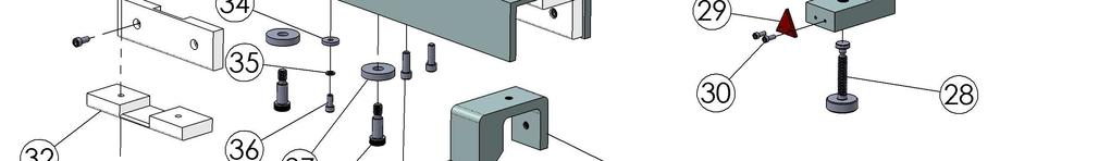
35 40522 Parts List Item No. Part Number Description Hitch Pin 2 Ref Only x 5/8 Hex Head Bolt 3 Ref Only #10 Split Lock Washer Mount Frame RS4000 Sensor Assembly Mount Grommet 7 Ref Only 5/16 x 3/4 OD Flat Washer 8 Ref Only 5/16-18 x 1 1/4 Hex Head Bolt Lock Stable 35
36 RS4000 Laser Kit---Part #
37 40603 Parts List Item No. Part Number Description Laser-Cannon w/ Scope* Key Box / Power Cable Case w/ Inserts * must be purchased with a case. 37
38 RS4000 Laser/Cannon---Part #
39 40530 Parts List Item No. Part Number Description Scope Assembly Scope Mount (Set of 2) Top Mount Base Vial Mount Ring Scope Mount Tube Vial Assembly 7 Ref Only 6-32 x 5/8 Pan Head Slot Screw Rear Cover Plate 9 Ref Only 6-32 x 3/4 Flat Head Slot Screw 10 Ref Only x 3/16 Knurled Tip Set Screw 11 Ref Only x 1/2" Knurled Tip Set Screw Power Cable Assembly Attenuator Knob 14 Ref Only 8-32 x 3/8 Flat Head Slot Screw 39

40 RS4000 Laser Kit --- Part #
41 40605 Parts List Item No. Part Number Description Laser-Cannon w/ Scope & Eye Bender* Key Box / Power Cable Case w/ Inserts * must be purchased with a case. 41

42 RS4000 Laser/Cannon --- Part #
43 40533 Parts List Item No. Part Number Description Scope Assembly Scope Mount (Set of 2) Top Mount Base Mount Ring Scope Mount Tube Eye Bender Mount 7 Ref Only 6-32 x 1/2" Button Head Screw Eye Bender Assembly 9 Ref Only 6-32 x 1/2" Socket Cap Screw 10 Ref Only x 3/16 Knurled Tip Set Screw 11 Ref Only x 1/2" Knurled Tip Set Screw 12 Ref Only x 3/16 Knurled Tip Set Screw 43


44 RS4000 Tripod/Laser Mount---Part #
45 40535 Parts List Item No. Part Number Description Front Support** Catch Block* 3 Ref Only 1/4-20 x 3/4 Socket Head Cap Screw 4 Ref Only 5/16-18 x 5/8 Soc Cup Point Set Screw Bumper* Clamp Assembly** 7 Ref Only 6-32 x 5/16 Socket Head Cap Screw Rear Support** 9 Ref Only x 1/2 Cone Point Set Screw 10 Ref Only 8-32 x 3/8 Socket Head Cap Screw Spring* 12 Ref Only 1/2-13 x 1/2 Socket Head Set Screw Plug* Rear Support Block* Teflon Washer* Wave Washer* Knob w/ Lock Insert* 18 Ref Only 3/8-5/16-18 x 3/4 S.H. Shoulder Bolt 19 Ref Only 8-32 x 3/8 Socket Head Cap Screw Line Adjustment Assembly* 21 Ref Only 5/16-18 x 1 Socket Head Cap Screw Spacer/Wear Plate* Wear Plate 24 Ref Only x 1/2 Socket Head Cap Screw Snap Ring Spacer/Wear Plate 27 Ref Only x ¼ Socket Head Cap Screw Knob Assembly w/ Swivel Pad Pointer 30 Ref Only 6-32 x 3/8 Socket Head Cap Screw 31 Ref Only x 9/16 Socket Head Cap Screw Spacer/Wear Plate 33 Ref Only x 1/2 Socket Head Cap Screw Spacer/Washer 35 Ref Only # 10 Split Lock Washer 36 Ref Only x 1/2 Socket Head Cap Screw Spacer/Washer Front Clamp Frame w/ Insert Rear Clamp Frame w/ Inserts Rear Support Assembly Complete Front Support Assembly Complete * Will directly replace the original parts used in the Classic Tripod Assembly. **40105 & must also include to repair an Classic Tripod Assembly. 45

46 RS4000 Cart/Buggy---Part # 40540, 40541, 40542, 40543, & Buggy Buggy Buggy Buggy Buggy Buggy 46
47 40540, 40541, 40542, 40543, & Parts List Item No. Part Number Description Wheel/Axel Assembly Complete 2 Ref Only 3/8-16 x 5/8 Socket Head Cap Screw Storage Pin Battery Box Universal Metric/Standard Scale 6 Ref Only 1/4-20 x 2 1/4" Hex Head Bolt 7 Ref Only 1/4" Flat Washer 8 Ref Only 1/4" Split Lock Washer 9 Ref Only 1/4-20 Hex Nut Whip Flag Handle Bias Clamp Assembly Complete Bias Clamp Bracket 14 Ref Only 5/16-18 x 3 Hex Head Bolt 15 Ref Only 5/16 Split Lock Washer 16 Ref Only 5/16-18 Hex Nut 47

48 RS Solar Cart/Buggy---Part # (Pg 1 of 2) 48

49 RS Solar Cart/Buggy---Part # (Pg 2 of 2) 49
50 40546 Parts List Item No. Part Number Description 1 Not Available 56.5 Solar Buggy Frame Wheel/Axel Assembly Complete 3 Ref Only 3/8-16 x 5/8 Socket Head Screw Solar Buggy Handle (Short) Storage Lock 5 Alt Storage Pin (Non-Locking) 6 Ref Only Chain Universal Metric/Standard Scale 8 Ref Only 1/4-20 x 2 1/4 Hex Head Bolt 9 Ref Only 1/4 Flat Washer 10 Ref Only 1/4" Split Lock Washer 11 Ref Only 1/4-20 Hex Nut Reflective Decal 13 Ref Only Rivet 14 Ref Only 1/4" Fender Washer Large Solar Panel Charge Control Housing V 55AH AGM Battery Electronics Mounting Panel 19 Ref Only 5/8-1/2-13x3/4 Shoulder Bolt Battery Holddown 21 Ref Only 1/4"-20 x 7 Carriage Bolt Battery Retainer 23 Ref Only 1/4"-20 x 3/4" Hex Head Bolt 24 Ref Only #10 Lock Washer 25 Ref Only x ½ Phillips Panhead Small Solar Panel Safety Light Safety Light Mount 29 Ref Only U-Nut, 1/4" Connector Blank 31 Ref Only 4-40 x 3/8 Phillips Panhead Grommet Standoff 34 Ref Only 1/4"-20 x 1 1/4" Hex Head Bolt Grommet Standoff Clamp Assembly Solar Panel Screen Protector, Large Solar Panel Screen Protector, Small 50
")
51 RS4000 Plasser Servo---Part # & (Pg 1 of 3) 51
52 RS4000 Plasser Servo---Part # & (Pg 2 of 3) 52
")
53 RS4000 Plasser Servo---Part # & (Pg 3 of 3) 53
54 40550 & Parts List (Pg 1 of 2) Item No. Part Number Description Plasser Servo Assembly w/o Motor Plasser Servo Assembly w/ RA Motor Wire Guide Assembly, Complete Hitch Pin Limit Switch Actuator Outer Bearing Shim Bearing Spacer Limit Switch Limit Switch Mounting Bracket Bearing Block Drive Support Plate Universal Standard Metric Scale Jack Screw* Support Rod Bellows/Flexible Shield w/ Clamps (SET) Sensor Plate Brass Nut* Nut Guide Pointer Bracket X5 Cast Housing Cover Plate Jack Screw Bearing Bearing Retainer Bearing Spacer Non-Metallic Washer/Shim Crank Shaft (For use w/ RA Motor)** Sleeve (For use w/ RA Motor)** Non-Metallic Shoulder Washer Terminal Block Motor Mounting Plate (For use w/ RA Motor)** RA 24VDC Servo Motor** RA Motor Arm** RA Servo Motor Assembly w/ Sleeve Motor Mount Plate (For use w/ Plsr Motor) 35 Ref Only 8-32 x 3/4" Flat Head Screw 36 Ref Only x 3/4" Pan Head Slot Screw 37 Ref Only #10 Split Ring Lock Washer** 38 Ref Only 1/4-20 x 4 Hex Head Screw 39 Ref Only 1/4 Flat Washer 40 Ref Only x 2 Pan Head Slot Screw 54
55 40550 & Parts List (Pg 2 of 2) Item No. Part Number Description 41 Ref Only #10 External Tooth Lock Washer 42 Ref Only 1/4-20 x 1/2" Hex Head Screw 43 Ref Only 1/4" External Tooth Lock Washer 44 Ref Only 1/4 Flat Washer 45 Ref Only 1/4-20 Hex Nut 46 Ref Only 1/4-20 x 3/4" Hex Head Screw 47 Ref Only 1/4" Internal Tooth Lock Washer 48 Ref Only 1/8 x 3/4" Spring Pin 49 Ref Only 1/2-20 x 5/8 Pan Head Slot Screw 50 Ref Only 1/4-20 x 1 Flat Head Screw 51 Ref Only 3/8-16 x 3/4" Hex Head Screw 52 Ref Only 3/8 External Tooth Lock Washer 53 Ref Only 3/8 Flat Washer 54 Ref Only x 3/4" Flat Head Screw 55 Ref Only 5/16-18 x 3 1/2" Hex Head Screw 56 Ref Only 5/16 Internal Tooth Lock Washer 57 Ref Only 1/4-20 x 3/4" Socket Head Screw 58 Ref Only 1/4-20 Split Ring Lock Washer 59 Ref Only 5/16-18 x 3 Hex Head Screw 60 Ref Only 5/16-18 Hex Nut 61 Ref Only 6-32 x 3/8 Pan Head Slot Screw 62 Ref Only #6 Split Ring Lock Washer 63 Ref Only x 5/8 Hex Head Screw 64 Ref Only Thd, 1 Long x 1/4" Dia. Shoulder Bolt** 65 Ref Only Hex Nut** 66 Ref Only 8mm-1.25 Serrated Flange Nut** 67 Ref Only 1/4-20 x 5/8 Button Head Screw** 68 Ref Only 1/4-20 x 1 Hex Head Screw 69 Ref Only x 3/16 Cup Point Set Screw Crank Shaft (For use w/ Plsr Motor) Sleeve (For use w/ Plsr Motor) *Updated Part-These parts must be replaced as a set in Yellow assemblies. ** For use with Rail Alignment standard servo motor and its parts only. This part will not work with the optional Plasser-Theurer motor or its parts. Available directly from Plasser: Plasser-Theurer Servo Motor --- Part # EL-T34.00P Plasser-Theurer Servo Motor Arm --- Part # EL-T34.03-SHORT 55

56 RS4000 Jackson Servo---Part # (Pg 1 of 3) 56

57 RS4000 Jackson Servo---Part # (Pg 2 of 3) 57

58 RS4000 Jackson Servo---Part # (Pg 3 of 3) 58
59 40551 Parts List (Pg 1 of 2) Item No. Part Number Description Jackson Servo Assembly Bearing Block Bearing Shim Bearing Spacer Lower Bearing Block Drive Support Plate Support Plate Spacer Universal Standard/Metric Scale Scale Spacer Limit Switch Mounting Bracket Limit Switch Jack Screw* Support Rod Bellows/Flexible Shield w/ Clamps (SET) Sensor Plate Brass Nut* Nut Guide Pointer Bracket Limit Switch Actuator X5 Cast Housing Cover Plate Jack Screw Bearing Bearing Retainer Bearing Spacer Non-Metallic Washer/Shim Crank Shaft Sleeve Non-Metallic Shoulder Washer Terminal Block Motor Mounting Plate VDC Servo Motor Motor Arm Servo Motor Assembly w/ Sleeve 35 Ref Only 8-32 x 3/4" Flat Head Screw 36 Ref Only x 3/4" Pan Head Slot Screw 37 Ref Only #10 Split Ring Lock Washer 38 Ref Only 1/4-20 x 3 Hex Head Screw 39 Ref Only 1/4" Flat Washer 40 Ref Only x 2 Pan Head Slot Screw 41 Ref Only #10 External Tooth Lock Washer 59
60 40551 Parts List (Pg 2 of 2) Item No. Part Number Description 42 Ref Only 1/4-20 x 1/2" Hex Head Screw 43 Ref Only 1/4-20 x 3/4 Pan Head Slot Screw 44 Ref Only 1/4" Flat Washer 45 Ref Only 1/4-20 Hex Nut 46 Ref Only 1/4-20 x 3/4" Hex Head Screw 47 Ref Only 1/4" Internal Tooth Lock Washer 48 Ref Only 1/8 x 3/4" Spring Pin 49 Ref Only 1/4-20 x 1 1/2" Hex Head Screw 50 Ref Only 1/4-20 x 1 Flat Head Screw 51 Ref Only 3/8-16 x 3/4" Hex Head Screw 52 Ref Only 3/8 External Tooth Lock Washer 53 Ref Only 3/8 Flat Washer 54 Ref Only x 3/4" Flat Head Screw 55 Ref Only 5/16-18 x 3 1/2" Hex Head Screw 56 Ref Only 5/16 Internal Tooth Lock Washer 57 Ref Only 1/4-20 x 3/4" Socket Head Screw 58 Ref Only 1/4" Split Ring Lock Washer 59 Ref Only 5/16-18 x 3 Hex Head Screw 60 Ref Only 5/16-18 Hex Nut 61 Ref Only 6-32 x 3/8 Pan Head Slot Screw 62 Ref Only #6 Split Ring Lock Washer 63 Ref Only x 5/8 Hex Head Screw 64 Ref Only Thd, 1 Long x 1/4" Dia. Shoulder Bolt 65 Ref Only Hex Nut 66 Ref Only 8mm-1.25 Serrated Flange Nut 67 Ref Only 1/4-20 x 5/8 Button Head Screw 68 Ref Only 1/4-20 x 1 Hex Head Screw 69 Ref Only x 3/16 Cup Point Set Screw Stabilizer Pad Beveled Wheel Assembly w/ Bearings Wheel Bushing 73 Ref Only 1/2-13 x 3 Hex Head Screw 74 Ref Only 1/2" Flat Washer 75 Ref Only 1/2-13 Hex Nut 76 Ref Only 1/8 x 1 1/4" Spring Pin Support Channel Weldment Slide Bar *Updated Part-These parts must be replaced as a set in Yellow assemblies. 60

61 RS4000 Jackson Servo Extension---Part #
62 40231 Parts List Item No. Part Number Description Extension Arm Assembly Knob Assembly Clamp Block Pointer Scale Pin Knob 8 Ref Only #10 Flat Washer 9 Ref Only #10 External Tooth Lock Washer 10 Ref Only x 1/2" Pan Head Slot Screw 11 Ref Only 1/4-20 x 3/8 Pan Head Slot Screw 12 Ref Only 1/4" External Tooth Lock Washer 13 Ref Only 1/4" Narrow Washer 14 Ref Only 3/8 Flat Washer 15 Ref Only 3/8-16 Lock Nut 62
 63")
63 RS4000 Canron Servo---Part # 40552, 40554, & (Pg 1 of 3) 63

64 RS4000 Canron Servo--- Part # 40552, 40554, & (Pg 2 of 3) 64

65 RS4000 Canron Servo--- Part # 40552, 40554, & (Pg 3 of 3) 65
66 40552, 40554, & Parts List (Pg 1 of 2) Item No. Part Number Description Canron Servo Assembly Outer Bearing Shim Bearing Spacer Bearing Block Mounting Bracket Drive Support Plate Universal Standard/Metric Scale Guide Rail Anchor Plate Limit Switch Mounting Bracket Limit Switch Jack Screw* Support Rod Bellows/Flexible Shield w/ Clamps (SET) Sensor Plate Brass Nut* Nut Guide Pointer Bracket Stop Block Hitch Pin Trip Block Standoff Plug Extension Arm X5 Cast Housing Cover Plate Jack Screw Bearing Bearing Retainer Bearing Spacer Non-Metallic Washer/Shim Crank Shaft Sleeve Non-Metallic Shoulder Washer Terminal Block Motor Mounting Plate VDC Servo Motor Motor Arm Servo Motor Assembly w/ Sleeve 40 Ref Only 1/4-20 x 4 Hex Head Screw 41 Ref Only 1/4" Flat Washer 66
67 40552, 40554, & Parts List (Pg 2 of 2) Item No. Part Number Description 42 Ref Only 1/4-20 Hex Nut 43 Ref Only 1/4" Split Ring Lock Washer 44 Ref Only 1/4-20 x 3/4" Hex Head Screw 45 Ref Only 1/4" Internal Tooth Lock Washer 46 Ref Only 1/8 x 3/4" Spring Pin 47 Ref Only 1/4-20 x 2 Hex Head Screw 48 Ref Only 1/4-20 x 5/8 Pan Head Slot Screw 49 Ref Only 1/4" Flat Washer 50 Ref Only 1/4" External Tooth Lock Washer 51 Ref Only 1/4-20 x 1/2" Hex Head Screw 52 Ref Only #10 External Tooth Lock Washer 53 Ref Only x 2 Pan Head Slot Screw 54 Ref Only x 3/4" Pan Head Slot Screw 55 Ref Only #10 Split Ring Lock Washer 56 Ref Only 6-32 x 3/8 Pan Head Slot Screw 57 Ref Only #6 Split Ring Lock Washer 58 Ref Only 1/4-20 x 3/4" Socket Head Screw 59 Ref Only 5/16-18 x 3 Hex Head Screw 60 Ref Only 5/16 Internal Tooth Lock Washer 61 Ref Only 5/16-18 Hex Nut 62 Ref Only 5/16-18 Flat Head Screw 63 Ref Only 5/16-18 x 3 1/2" Hex Head Screw 64 Ref Only x 1 1/2" Round Head Screw 65 Ref Only 3/8 Flat Washer 66 Ref Only 3/8 External Tooth Lock Washer 67 Ref Only 3/8-16 x 3/4" Hex Head Screw 68 Ref Only 1/4-20 x 1 Flat Head Screw 69 Ref Only x 5/8 Round Head Screw 70 Ref Only x 5/8 Hex Head Screw 71 Ref Only Thd, 1 Long x 1/4" Dia. Shoulder Bolt 72 Ref Only Hex Nut 73 Ref Only 8mm-1.25 Serrated Flange Nut 74 Ref Only 1/4-20 x 5/8 Button Head Screw 75 Ref Only 1/4-20 x 1 Hex Head Screw 76 Ref Only x 3/16 Cup Point Set Screw Beveled Wheel Assembly Not Pictured Beveled Wheel Assembly (42 Spec) Support Channel (39, 42 & 56.5 ) Slide Bar *Updated Part-These parts must be replaced as a set in Yellow assemblies. 67
68 RS4000 Canron Guide Wheel Assembly---Part # & Beveled Wheel Assembly Beveled Wheel Assembly 68
69 40297 & Parts List Item No. Part Number Description 1 Ref Only 3/8-16 x 1-3/4 Hex Head Bolt 2 Ref Only 5/16 Flat Washer Phenolic Isolator, Washer Phenolic Isolator, Cylinder UHMW Isolator Pad UHMW Isolator Pad (42 Spec) Wheel Mounting Bracket Wheel Mounting Bracket (42 Spec) 9 Ref Only 3/8-16 Nylon Lock Nut 10 Ref Only 5/8-11 x 2-1/4 Hex Head Bolt Wheel Washer Beveled Wheel w/ Bearing Wheel Bushing 14 Ref Only 5/8-11 Nylon Lock Nut 69
70 Troubleshooting Symptom The Laser/Cannon does not turn on. The Lasers working distance is reduced. The Sensor/Servo will not settle or it is constantly hunting. The Sensor is not responding to the laser. Possible Causes and Solutions Low or dead battery-charge Battery Dirty or corroded contacts-clean Contacts Damaged Keybox cable-replace Keybox Cable Damaged power cable on the Laser*-Send the Laser in for service *Never attempt to repair the laser on your own. This items contains High Voltage electronic componets. Personal injury or additional equipment damage could result. Low battery-charge Battery Enviornmental conditions are affecting the Laser- Heat shimmer, rain, snow, ice, fog, and dust are all examples of conditions that will affect the working distance of the equipment. Dirty or obstructed lens on the Laser and/or Sensor- Clean lenses Laser output is deminished-send Laser in for service The Laser was not properly aligned during set up- Check the Laser and Scope to ensure properly alignment. Send the unit in for calibration if necessary. Moisture is present on the Lenes of the Laser and/or Sensor-Ensure that the Lenes on the Laser and Sensor are dry and free from obstruction. System set up issues-it is essential for all of the componets of the system to be set up correctly. There are multiple components to include the Buggy, Tripod, Laser, and Servo that are either adjustable or have adjustable parts that must be correctly set up. Ensure that none of these items needs attention. The Sensor is responding to an alternate input-in most cases the Sensor will ignore white noise. However, it is possible that a Sensor facing the sun when it is low enough will incorrectly respond. Shade the Sensor from the sun if the situation applies. If this does not fix the problem, it may be necessary to send the Sensor in for repair. Environmental conditions are affecting the system- Ensure that the Lenes on the Laser and Sensor are dry and free from obstruction. Also ensure that nothing is blocking the sensor from seeing the Laser in the work area. Improper Laser Set-up-The Tripod that secures the Laser to the Buggy has multiple adjustments. Ensure that the Laser is correctly oriented toward the Sensor. Fuse Issue-Ensure that fuse F7, F10 and F11 in the Panel are not blown and are making good contact. Bad connection inside Panel-Ensure that the Sensor connection (J2) is properly seated and clean. Sensor Cable Damage/Failure- Replace the cable. Sensor Damage/Failure-Send the Sensor in for Service. 70
71 The Panel will not turn on. Panel power has been interrupted-ensure that the power cord from the power source to the Panel is not damaged and is properly attached to the power source and Panel. You can test for voltage in the power cord by using a voltage meter set for DC power. Pin A of the connector into the Panel should have 24 VDC, Pin B is the ground. Fuse Issue-Ensure that fuses F1 & F7 in the Panel are not blown and are making good contact. Bad connection inside Panel-Ensure that the 24 Volt Input (J4) connection below fuse F7 and the Switches (J5) connection are properly seated and clean. Panel Damage/Failure-Send the Panel in for repair. The Left and/or Right indicator lights on the panel will not turn off. The Left and/or Right indicator lights on the Lightbar will not turn off. Also, one or both of the Red Limit indicators is illuminated. The Left, Center or Right indicator lights on the Panel will not turn on. The Left, Center or Right indicator lights on the Lightbar will not turn on. Missing Limit Switch-The panel is looking for both of the limit switches located on the Servo. If the inputs from one or both of the switches is not present, the Panel will indicate this to you by turning on the corresponding indicator light. In addition the Panel will not function until this input is satisfied. Ensure that both of the limit switches are present, connected properly and are in good working condition. Limit Switch is engaged-ensure that the Servo is not completely to one end of travel activating one of the limit switches. Limit Switch or Cable Damage/Failure-It is also possible that if a limit switch has failed it will appear to be engaged. Replace the limit switch or the cable. Fuse Issue-Ensure that fuses F4, F5 & F6 in the Panel are not blown and are making good contact. Fuse Issue- Ensure that fuses F1, F2 & F3 in the Panel are not blown and are making good contact. Indicator Damage/Failure-Send the Panel in for repair. The Standby indicator light on the Panel will not turn on. The Power indicator light on the Panel will not turn on. The Limit indicator lights on the Lightbar will not turn on when the Servo reaches its limits. Fuse Issue- Ensure that fuse F12 in the Panel is not blown and is making good contact. Indicator Damage/Failure-Send the Panel in for repair Fuse Issue- Ensure that fuses F8 in the Panel is not blown and is making good contact. Indicator Damage/Failure-Send the Panel in for repair Fuse Issue- Ensure that fuses F6 in the Panel is not blown and is making good contact. Indicator Damage/Failure-Send the Panel in for repair 71
72 The Lightbar does not function. Lightbar power has been interrupted-ensure that the cord from the Lightbar to the Panel is not damaged and is properly attached to the Lightbar and Panel. Replace cable if damaged. Fuse Issue-Ensure that fuses F1, F2, F3 & F6 in the Panel are not blown and are making good contact. Bad connection inside Panel-Ensure that the Lightbar connection (J10) is properly seated and clean. Lightbar Damage/Failure-Send the Lightbar in for repair. The Servo does not function. Servo power has been interrupted-ensure that the cord from the Servo to the Panel is not damaged and is properly attached to the Servo and Panel. You can test for voltage in the power cord by using a voltage meter set for DC power. You should see +/- 24 VDC between the motor leads. Use the Manual Left/Right switch on the Panel to energize the circuit for this test. Motor Damage/Failure-Replace the servo motor. No signal from the Sensor-If the Servo responds to the manual Left/Right switch on the Panel, refer to The Sensor is not responding to the Laser above. Fuse Issue-Ensure the fuse F13 in the Panel is not blown and is making good contact. Bad connection inside the Panel-Ensure that the Motor connection (J3) is properly seated and clean. Servo Damage/Failure-Send the Servo in for repair. The Servo will not move in one direction. System acts Nervous all the time and I have swapped out serveral componets in an attempt to try and pin point the issue with no change in behavior from the system. Limit Switch is Activated-Check to ensure that the Servo is not at its travel limit in the direction you want it to move. If it is, you should have a Red Limit light illuminated on your Lightbar. If you are trying to get the servo to move off of a limit switch but it will not respond, it may be because the limit switches are reveresed. This is easily figured out by determaining if the Servo motor is still attempting to drive the Servo in the direction that the limit switch that appears to be activated. Activate the oposite side limit switch and see if the power to the motor is cut. Switch the limit switch connections on the Panel if this is the problem. No signal from the Sensor-If the Servo responds to the manual Left/Right switch on the Panel, refer to The Sensor is not responding to the Laser above. Fuse Issue-Ensure that fuses F4 and F5 in the Panel are not blown and are making good contact. Bad connection inside the Panel-Ensure that the Motor connection (J3) is properly seated and clean. Servo Damage/Failure-Send the Servo in for repair. Dirty Supply Power- We have found that with some tampers, there is a lot of noise in the supply power and/or traveling on the ground. If this noise is extremely bad, it can cause the RS4000 system to act very nervous. It may be nesecary to filter the supply power with a good line conditioner to correct this problem. 72
73 Product Indentification The Rail System 4000 product model numbers listed below each have an external identification label on them. Enter the serial numbers below along with the purchase dates. Retain this information for your records, refer to it when you need to contact us with questions or concerns. Serial # Purchase Date Panel Model # Lightbar Model # Sensor Model # Laser Model # 40530/3 Solar Cart Model # Warranty Rail Alignment LLC (Rail Alignment) warrants to the original end user (Customer) that this product will be free from defects in workmanship and materials under normal use, and provided any and all operating and maintenance instructions are strictly respected, in particular in case of extreme and/or continuous applications/use of the product. Any evidence of an attempt to repair a Rail System 4000 (RS4000) component by other than factory authorized personnel using Rail Alignment certified replacement parts will automatically void the warranty. Rail Alignments liability under this warranty is limited to repairing or replacing any product returned to a factory authorized service facility for that purpose. The foregoing states the entire liability of Rail Alignment in connection with the RS4000 components, and they shall not be held responsible for any consequential damage of any kind. The foregoing is in lieu of all other warranties expressed or implied. The user of the RS4000 components is expected to follow all operating instructions, periodically checking the components and the work as it progresses. Checking and ensuring the calibration of the system and/or its components is the responsibility of the user. Calibration and maintenance is not covered by the above warrany. Warranty Period: 12 months from date of purchase from Rail Alignment. Laser Specialists, Inc W 156 th St Olathe KS PH: FX: The only factory authorized service center for all of your Rail System 4000 components! 73
74 Calibration The RS4000 components are calibrated to the defined accuracy specifications at the factory, except where customer assembly is required. Is is recommended to check your RS4000 components for calibration periodically before using them to ensure calibration is maintained. If any factory set items require calibration, send them to your nearest authorized service center. Do not attempt component calibration unless you plan to change the calibration. Calibration should be performed only by a qualified individual that understands basic calibration principles. Transport When transporting the various components of the RS4000, always use the complete original Rail Alignment packaging (case and/or cardboard box). When transporting the Laser in the field, always make sure that you carry it in its carrying case. When transporting RS4000 components by rail, air, ship or motor vehicle, always use the complete original packaging (case and/or cardboard box), or its equivalent to protect it against damage from impact, shock and vibration. After transport, or after long periods of storage, inspect each RS4000 component for damage and proper functionality. Remove any RS4000 components from service and contact your service provider if you find that any of your equipment has been damaged or does not function properly. Storage Temperature Limits -40 to 158 F (-40 to 70 C). Respect the temperature limits when storing the components, particularly in summer if the components are in an none-climate controlled enclosure. Damp components must be unpacked. Dry the components, the case and any accessories at not more then 108 F and clean them. Do not repack until everything is completely dry. Cleaning and Drying Windows Never touch windows with your fingers. Use only a clean, soft, lint-free cloth for cleaning. If necessary, moisten the cloth with water or pure alcohol. Use no other liquids; these may attack the polymer components and cause failure. Maintenance Warning: Only Rail Alignment authorized workshops are entitled to repair these products. DO NOT ATTEMPT TO OPEN THE LASER ASSEMBLY. Continued next page 74
75 It is the user s responsibility each time the laser is set up, to visually inspect the laser housing to verify that it has not been damaged so as to allow access to laser light from the interior of the laser from any place other then its intended source. If damage to the laser or a malfuntion is present, discontinue use of the equipment and return it to your nearest service center for repair. Safety/Responsibilities Caution: Use of controls or adjustments or performance of procedures other then those specified herein may result in hazardous laser light exposure. Warning: HeNe laser power up to 4.75mW is emitted through the laser window. Rail Alignment is responsible for supplying the product, including the user manual and original accessories in a completely-safe condition. The manufucturers of non-rail Aligment accessories for any RS4000 components and or equipment controlled by the RS4000 system, are responsible for developing, implementing and communicating safety concepts for their products, and are also responsible for the effectiveness of those safety concepts in combination with Rail Alignment product. The person responsible for the RS4000 equipment must ensure that it is used in accordance with the instructions. This person is also accountable for the training and the deployment of personnel who use the instrument and for the safety of the equipment in use. The person in charge of the equipment has the following duties: To understand the safety instructions on the product and the instructions in the user manual. To inform Rail Aligment immediately if the equipment becomes unsafe. Warning: Adverse use can lead to injury, malfunction, and material damage. It is the task of the person responsible for the RS4000 equipment to inform the user about hazards and how to counteract them. The RS4000 equipment is not to be used until the user has been instructed how to work with it. All users must follow the safety directions given by the manufacturer and the directions of the person responsible for the equipment. Laser Classification Warning: Avoid possible exposure to laser light. Class 3R Laser: Class 3R lasers are considered safe if handled correctly, with restricted beam viewing and maintained in accordance with the instructions. Changes or modifications not expressly approved by Rail Alignment could void the user s authority to operate this equipment. 75


76 Illustration of the Safety Decals Affixed to the front of the Laser-- FCC Statement This equipment complies with limits for a Class A digital device, pursuant to part 15 of the FCC rules. This device complies with Part 15 of the FCC Rules. Operation is subject to the following conditions: (1) This device may not cause harmful interference, and (2) this device must accept any interference received, including interference that may cause undesired operation. Warning: Changes or modifications not expressly approved by Rail Alignment could void the user s authority to operate the equipment. Copyright Notice Copyright 2016 by Rail Alignment LLC. All rights reserved. Rail Alignment Proprietary Information NOTICE: The information/data contained herein is proprietary information of Rail Alignment LLC and is furnished for your controlled use, and shall not be copied or otherwise reproduced, nor in any manner disclosed to any third party, without Rail Alignment s prior written consent. Manual is subject to return on demand. The information in this manual supersedes all previous versions. 76
RS4000 Setup. Before you install the RS4000 system, check to ensure that nothing was damaged or lost during shipping.
 RS4000 Setup Before you install the RS4000 system, check to ensure that nothing was damaged or lost during shipping. If anything is damaged or missing, contact your salesman immediately. Mount Components
Assembly Instructions
 Assembly Instructions Part Number Description Model Approx. Assembly Time 99994-0903 Windshield Wiper Kit Mule SX 1 Hour WARNING Improper installation of this accessory could result in an accident causing
PARTS LIST CHARGER 2716 DB PLUS
 PARTS LIST CHARGER 2716 DB PLUS BASE ITEM PART NO. DESCRIPTION QTY. 101 6495511 CONTROL FRAME WELDMENT 1 102 9121390 11/32 I.D. X 11/16 O.D. X.051/.080 THICK SAE FLAT WASHER (5/16) 2 103 9121450 5/16-18
ProPass-200 Top Dresser
 Setup Manual Form No. 3365-184 Rev A ProPass-200 Top Dresser Model No. 44700-Serial No. 310000001 and Up Model No. 44701-Serial No. 310000001 and Up Model No. 44704 Model No. 44705 Model No. 44706 Model
PARTS LIST CHARGER 2020 AB CHARGER 2020 DB
 PARTS LIST CHARGER 2020 AB CHARGER 2020 DB 1 ITEM PART NO. DESCRIPTION QTY. 101 6495511 CONTROL FRAME WELDMENT 1 102 9121390 11/32 I.D. X 11/16 O.D. X.051/.080 THICK SAE FLAT WASHER (5/16) 2 103 9121450
PARTS LIST CHARGER 2716 DB PLUS
 PARTS LIST CHARGER 2716 DB PLUS BASE ITEM PART NO. DESCRIPTION QTY. 101 6495511 CONTROL FRAME WELDMENT 1 102 9121390 11/32 I.D. X 11/16 O.D. X.051/.080 THICK SAE FLAT WASHER (5/16) 2 103 9121450 5/16-18
INSTALLATION INSTRUCTIONS
 2807 INSTALLATION INSTRUCTIONS SECTION - AIR SPRING SECTION 2 - AIR ACCESSORY -6 ! IMPORTANT PLEASE DON T HURT YOURSELF, YOUR KIT OR YOUR VEHICLE. TAKE A MINUTE TO READ THIS IMPORTANT INFORMATION. This
PARTS LIST WRANGLER 2625 DB
 PARTS LIST WRANGLER 2625 DB 1 NOTES 2 BRUSH GEAR MOTOR ITEM PART NO. PART DESCRIPTION QTY. 2393001 COMPLETE MOTOR ASSEMBLY 1 101 3391221 NEGATIVE LEAD 1 102 3391201 1/4-20 X 7 3/4THRU BOLT 2 103 10-24
INSTALLATION INSTRUCTIONS
 28 INSTALLATION INSTRUCTIONS SECTION - AIR SPRING SECTION 2 - AIR ACCESSORY 2-5 ! IMPORTANT PLEASE DON T HURT YOURSELF, YOUR KIT OR YOUR VEHICLE. TAKE A MINUTE TO READ THIS IMPORTANT INFORMATION. This
PARTS LIST CHARGER 2025 AB CHARGER 2025 DB
 PARTS LIST CHARGER 2025 AB CHARGER 2025 DB 1 ITEM PART NO. DESCRIPTION QTY. 101 6495511 CONTROL FRAME WELDMENT 1 102 9121390 11/32 I.D. X 11/16 O.D. X.051/.080 THICK SAE FLAT WASHER (5/16) - PACK OF 10
Detroit Speed, Inc. Electric Headlight Door Kit Corvette P/N: &
 Detroit Speed, Inc. Electric Headlight Door Kit 1968-82 Corvette P/N: 122006 & 122007 The Detroit Speed Inc. Electric Headlight Door Kit replaces the stock vacuum actuated system on all 1968-82 Corvettes.
Safe-T-element Installation Instructions
 Safe-T-element Installation Instructions For: PTI STEZA (2x2 Burner Configuration) & PTI STEZB (3x1 Burner Configuration) Revision K (May. 3 2012) TABLE OF CONTENTS 1. PREPARATION... 3 1.1 General Safety
PARTS LIST WRANGLER 2625 DB
 PARTS LIST WRANGLER 2625 DB 1 NOTES 2 BRUSH GEAR MOTOR ITEM PART NO. PART DESCRIPTION QTY. 2393501 COMPLETE MOTOR ASSEMBLY 1 101 3391221 NEGATIVE LEAD 1 102 3391201 1/4-20 X 7 3/4THRU BOLT 2 103 10-24
PARTS LIST WRANGLER 26-VS
 PARTS LIST WRANGLER 26-VS ELECTRICAL WIRING ITEM PART NO. DESCRIPTION QTY. 1 2694161 UPPER WIRING HARNESS 1 2 2694171 LOWER WIRING HARNESS 1 3 2490811 BRUSH MOTOR WIRE ASSEMBLY 1 4 2396141 WIRE ASSEMBLY
Installation Instructions Table of Contents
 Installation Instructions Table of Contents Pre- Installation of Garage Storage Lift 2 Layout the Garage Storage Lift 3 Installing the strut Channels 3 Install the Drive Assembly 5 Install the Drive Shaft
Stay-IN-Play with Panic Stop Braking
 INSTALLATION INSTRUCTIONS TOWED VEHICLE BRAKING SYSTEM Stay-IN-Play with Panic Stop Braking SMI Manufacturing, Inc. P.O. Box 14040 Evansville, IN 47728 1-800-893-3763 www.smibrake.com SIP0906 Model SIP0603
Illustrated Parts & Packing List & Instructions 815 Rice Lake Street, Owatonna, MN 55060
 Illustrated Parts & Packing List & Instructions 815 Rice Lake Street, Owatonna, MN 55060 Great Plains Part #891-561C (Gandy Part #6245DS-GP) For Great Plains Turbo-Max 2400, 3000, 3500 & 4000 Models 45
Conflicts: Vehicles without a sunroof Vehicles with a single sunroof
 Toyota Sienna (Dual Sunroof) 2011-10.2 Overhead Video Part Number: 00016-00110 00016-00110-17 Fit Kit 00016-00120 00016-00120-17 Fit Kit Accessory Code: ED5 Conflicts: Vehicles without a sunroof Vehicles
SX1000 Service Manual SALES: CUSTOMER SERVICE:
 SX1000 Service Manual SALES: 800-278-3933 CUSTOMER SERVICE: 800-745-1373 Revision: August 1999 Table of Contents Section Page I. Overview 2 II. Troubleshooting Tables 3 III. Maintenance Procedures Procedure
Detroit Speed, Inc. Electric Headlight Door Kit Corvette P/N: &
 Detroit Speed, Inc. Electric Headlight Door Kit 1968-82 Corvette P/N: 122006 & 122007 The Detroit Speed Inc. Electric Headlight Door Kit replaces the stock vacuum actuated system on all 1968-82 Corvettes.
Advolution 2710 PARTS LIST MODELS , , /06 revised 5/09 FORM NO
 PARTS LIST MODELS 56422000, 56422002, 56422184 3/06 revised 5/09 06-3 09-5 TABLE OF CONTENTS 1 DESCRIPTION PAGE Body System... 2-3 Chassis System... 4-5 Decal System... 6-7 Electrical System... 8-9 Pad
TOYOTA FJ CRUISER / 4RUNNER COLD AIR INTAKE Section I Installation Preparation. 4.0L V6 (1GR) Roller Rocker Part Number(s): PTR
 Roller Rocker Part Number(s): PTR") Section I Installation Preparation Part Number(s): PTR03-89100 Kit Contents Item # Quantity Reqd. Description 1 1 Air Filter (P/N: PTR43-00083) 2 1 Upper Air Box 3 1 Lower Air Box 4 1 Hump Coupler 5 1
Section I Installation Preparation Part Number(s): PTR03-89100 Kit Contents Item # Quantity Reqd. Description 1 1 Air Filter (P/N: PTR43-00083) 2 1 Upper Air Box 3 1 Lower Air Box 4 1 Hump Coupler 5 1
WRANGLER 2016 WHEEL DRIVE, PAD ASSIST & ELECTRIC MODELS
 WRANGLER 2016 WHEEL DRIVE, PAD ASSIST & ELECTRIC MODELS BRUSH LIFT 101 9121960 3/8 EXTERNAL STAR LOCK WASHER 1 102 9122030 3/8-16 X 3/4 BUTTON HEAD SOCKET SCREW 1 103 2694261 CABLE 1 104 2391771 90 HOSE
RYOBI 10 in. SLIDING MITER SAW w/laser MODEL NO. TSS100L REPAIR SHEET
 RYOBI 10 in. SLIDING MITER SAW w/laser MODEL NO. TSS100L REPAIR SHEET 119 96 83 1 84 85 116 86 114 92 82 117 113 112 115 97 175 176 120 177 121 1 2 3 122 81 87 128 164 1 80 88 174 114 6 53 163 19 3 141
Installation Guide CLAAS Lexion Combines with 9 inch Elevators
 Installation Guide CLAAS Lexion Combines with 9 inch Elevators 955614_01 4/17 1 Table of Contents System Overview 3 Quick Start Guide 4 Flow Sensor Installation 5 Hydraulic Elevator Adjustment Kit Installation
Installation and Service Manual
 RESIDENTIAL PLATFORM LIFTS RPL400 / RPL600 Installation and Service Manual WARNING! STRICT ADHERENCE TO THESE INSTALLATION INSTRUCTIONS IS REQUIRED to promote the safety of those installing this product,
HIGH RISE POWER ANGLE KIT
 HIGH RISE POWER ANGLE KIT P/N 33-0100 OWNER S MANUAL Application HIGH RISE PUSH TUBE 33-0000 & 34-0000 ATTENTION DEALER: CUSTOMER MUST RECEIVE A COPY OF THIS MANUAL AT THE TIME OF SALE. Before you begin,
Conflicts: Highlander without sunroof
 Toyota Highlander (Sunroof) 2011-8.5 Overhead Video Part Number: 00016-00125; Fit Kit-00016-00125-02 Accessory Code: ED9 Conflicts: Highlander without sunroof Kit Contents: Item # Qty. Component Description
Parts Manual for LAWN TRACTORS MANUAL CLUTCH HYDRO DRIVE SERIES F MODELS LT145H33FBV LT145H38FBV ELT145H33FBV
 Parts Manual for LAWN TRACTORS MANUAL CLUTCH HYDRO DRIVE SERIES F MODELS LT145H33FBV LT145H38FBV ELT145H33FBV IT IS THE POLICY OF SNAPPER TO IMPROVE ITS PRODUCTS WHENEVER IT IS POSSIBLE AND PRACTICAL TO
ISO1000R Service Manual SALES: CUSTOMER SERVICE:
 ISO1000R Service Manual SALES: 800-278-3933 CUSTOMER SERVICE: 800-745-1373 Revision: August 1999 Table of Contents Section Page I. Overview 2 II. Troubleshooting Tables 3 III. Maintenance Procedures Procedure
SUT-450-I ASSEMBLY REQUIREMENTS
 SUT-450-I Torque wrench, carpenters square, wire cutters, Phillips screwdriver, 7/16, 9/16, and 3/4 combination wrenches, ratchet, 9/16,3/4,13/16, and 7/8 sockets. ASSEMBLY REQUIREMENTS *Torque all T-bolt
Illustrated Parts & Packing List & Instructions 815 Rice Lake Street, Owatonna, MN 55060
 Illustrated Parts & Packing List & Instructions 815 Rice Lake Street, Owatonna, MN 55060 Great Plains Part #891-622C (Gandy Part #6245DS-TT) Great Plains Turbo-Till & Turbo-Chopper 2400/3000 Models 45
Installation Instructions COMPETITION/PLUS SHIFTER Ford Mustang MT82 6-Speed Manual Transmission Catalog#
 Installation Instructions COMPETITION/PLUS SHIFTER 2015-2017 Ford Mustang MT82 6-Speed Manual Transmission Catalog# 3916037 Rev. 00 WORK SAFELY! For maximum safety, perform this installation on a clean,
Installation and Service Manual M² Sync Room Slideout System without Room Lock Connectors on Control Box
 Installation & Service Manual M² Sync Room Slideout System w/o Room Locks: for Slideout Control Box# 1510000143 and 1510000198 Figure 1 01/13 Power Gear #3010002088 Rev. 0C Installation and Service Manual
Installation Instructions HURST COMPETITION AND BILLET/PLUS SHIFTER Mustang w/5-speed Manual Transmission (GT only)
") Installation Instructions HURST COMPETITION AND BILLET/PLUS SHIFTER 2005-2010 Mustang w/5-speed Manual Transmission (GT only) Catalog# 3915201 WORK SAFELY! For maximum safety, perform this installation
Installation Instructions HURST COMPETITION AND BILLET/PLUS SHIFTER 2005-2010 Mustang w/5-speed Manual Transmission (GT only) Catalog# 3915201 WORK SAFELY! For maximum safety, perform this installation
PARTS LIST WRANGLER 2016 AE, AB, DB
 PARTS LIST WRANGLER 2016 AE, AB, DB 1 ITEM PART NO. DESCRIPTION QTY. 101 2397081 MOTOR HOUSING 1 102 9120790 10 X 5/8 PAN HEAD PHILLIPS SHEET METAL SCREW [PACK OF 10] 4 103 2397991 WATER SOLENOID 24 VOLT
INSTALLATION INSTRUCTIONS FOR DSP9600/9100 WHEEL BALANCER
 Form 5063T, 06-05 Supersedes Form 5063T, 02-04 INSTALLATION INSTRUCTIONS FOR DSP9600/9100 WHEEL BALANCER This document provides the information needed to install the DSP9600/9100 Wheel Balancer. NOTE:
Troubleshooting Guide: 255 LED Light
 Troubleshooting Guide: 255 LED Light Note Use only factory replacement lights (refer to parts list for order number). Caution Carefully handle parts near membranes and wire harnesses. Allow the light to
WRANGLER 1708CE, 2008CE
 WRANGLER 1708CE, 2008CE CONTROL PANEL ASSEMBLY ITEM PART NO. DESCRIPTION QTY. 101 5490161 FULLY INSULATED FEMALE TERMINAL 14-16 2 102 0693141 RUBBER SWITCH BOOT 2 103 0691851 1/2 INTERNAL STAR LOCK WASHER
High Lift Transmission Jack
 655 Eisenhower Drive Owatonna, MN 55060 USA Phone: (507) 455-7000 Tech. Serv.: (800) 533-6127 Fax: (800) 955-8329 Order Entry: (800) 533-6127 Fax: (800) 283-8665 International Sales: (507) 455-7223 Fax:
Advolution 2710 UHR
 Advolution 2710 UHR 70-1700 PARTS LIST Advance MODELS 56422000, 56422002, 56422184 Nilfisk MODEL 56422001 3/06 revised 8/08 SECTION 5.9.1 06-3 TABLE OF CONTENTS Advolution 2710 / UHR 70-1700 D 5.9.1 1
POLARIS 4500 HD WINCH KIT
 POLARIS 4500 HD WINCH KIT P/N 2883860 APPLICATION Verify accessory fitment at Polaris.com. BEFORE YOU BEGIN Read these instructions and check to be sure all parts and tools are accounted for. Please retain
INSTALL MANUAL. FOR ON LINE ORDERING- E Commerce Visit Our Website
 INSTALL MANUAL FOR ON LINE ORDERING- E Commerce Visit Our Website WWW.PRESSUREGUARD.COM Contact Information Technical Support: Chris@pressureguard.com Sales Support: Sales@pressureguard.com By Phone: 615-227-6024
Part Name/Description Part Number Quantity Instruction Kit Metalfor Flow Sensor
 NOTE: Indented items indicate parts included in an assembly listed above Part Name/Description Part Number Quantity Instruction Kit Metalfor 4101091 1 Flow Sensor 4001356 1 Deflector plate 2000612-1 1
Rostselmash Torum 740
 Note: Indented items indicate parts included in an assembly listed above Quantity by Model Part Name/Description Part Number 740 Combine Kit Torum 740 4100762 1 Threaded Arm Assembly 2000311-2 1 Header
Midwest Industries, Inc. Ida Grove, IA Page 1
 SSV40108HAC - Hydraulic Hoist with 120 Volt Pump SSV40108HDAC - Hydraulic Hoist, Deep Water, with 120 Volt Pump SSV40108HDC - Hydraulic Hoist with 12 Volt Pump SSV40108HDDC - Hydraulic Hoist, Deep Water,
xtablet T7000 Vehicle Mount Kit
 xtablet T7000 Vehicle Mount Kit Installation & Users Guide Last Updated: January 19, 2012 Find the latest updates in the Support section in the MobileDemand website at: www.ruggedtabletpc.com. Questions?
4050A. Tire Changer. Parts Identification. For servicing single piece automotive and most light truck tire/wheel assemblies
 4050A Tire Changer For servicing single piece automotive and most light truck tire/wheel assemblies Parts Identification READ these instructions before placing unit in service KEEP these and other materials
215E. Operator and Parts Manual MM158
 5E Operator and Parts Manual MM58 This manual is furnished with each new TENNANT Model 5E This manual consists of Specifications; Operation; Maintenance; Appendix; the How To Use This Manual; Low Dump
INSTALLATION & OWNER S MANUAL
 Rev. C p. 1 of 21 INSTALLATION & OWNER S MANUAL F5205 HARD SIDED CAB KIT INSTALLATION & OWNER S MANUAL The contents of this envelope are the property of the owner. Be sure to leave with the owner when
IMPORTANT! DO NOT THROW AWAY THE SHIPPING CARTON AND PACKING MATERIAL
 Operator s Manual IMPORTANT! DO NOT THROW AWAY THE SHIPPING CARTON AND PACKING MATERIAL ii Table of Contents Operator Safety... 1 Introduction... 2 Unpacking and Setup... 3 Unpacking... 3 Setup... 4 ROCKET
Parts Catalog. S-Series Slicer Automatic. Model:
 , 07 99509 ECN 077 Parts Catalog S-Series Slicer Automatic Model: SGA SGA 05/08/07 Rev. J IMPORTANT! TO EXPEDITE SHIPMENT OF PARTS, ALWAYS SPECIFY MODEL, REV, PART NUMBER, AND SERIAL NUMBER OF UNIT. GLOBE
VHM-P (Non-Locking) and VHM-PL (Locking) Variable Height Arm with Slide-In Mounting Plate
 and VHM-PL (Locking) Variable Height Arm with Slide-In Mounting Plate") 3875 Cypress Drive Petaluma, CA 94954 800.228.2555 +1.707.773.1100 Fax 707.773.1180 www.gcx.com VHM-P (Non-Locking) and VHM-PL (Locking) Variable Height Arm with Slide-In Mounting Plate (Refer to qualified
3875 Cypress Drive Petaluma, CA 94954 800.228.2555 +1.707.773.1100 Fax 707.773.1180 www.gcx.com VHM-P (Non-Locking) and VHM-PL (Locking) Variable Height Arm with Slide-In Mounting Plate (Refer to qualified
Automated Steering Hydraulic Installation Kit
 Automated Steering Hydraulic Installation Kit P/N: ED-JD4060 Fits John Deere Tractor Models: 4560 4760 4960 Overview A series of equipment specific hydraulic installation kits have been developed to work
Parts Catalog. S-Series Slicer Standard Automatic Frozen Option S13A. Model:
 , 07 995 ECN 077 Parts Catalog SA S-Series Slicer Standard Automatic Frozen Option Model: SA 05/08/07 Rev. H IMPORTANT! TO EXPEDITE SHIPMENT OF PARTS, ALWAYS SPECIFY MODEL, REV, PART NUMBER, AND SERIAL
FAX
 INSTALLATION INSTRUCTIONS 6090 Air Suspension Kit (pat. pending) 1999-2006 Tahoe, Suburban, Avalanche, Yukon Thank you for purchasing a quality Hellwig Product. PLEASE READ THIS INSTRUCTION SHEET COMPLETELY
Model ET 5000W Operation and Service Manual
 Model ET 5000W Operation and Service Manual Patented 5/16 BALL Load Capacity: 5000 lbs The ET 5000W ESCALATE TRAILER offers ground level roll-on loading and roll-off unloading of equipment with non-tilting
PARTS LIST WRANGLER 1710AB, 2010AB 120V AND 240V, TYPE F PLUG
 PARTS LIST WRANGLER 1710AB, 2010AB 120V AND 240V, TYPE F PLUG CONTROL PANEL ASSEMBLY 101 1394151 ROUND POWER SWITCH 1 102 0693141 RUBBER SWITCH BOOT 2 103 9122465.516 I.D. X.813 O.D. X.027/.030 THICK FLAT
VECTRIX VX-2 SERVICE MANUAL. Version 1.0/May 2011 VECTRIX, LLC
 www.vectrix.com CONTENTS SECTION A: Tools 1 Tools Needed SECTION B: Mechanical Parts 1 Front Fairing 2 Front Console Cover 3 Speedometer Cover 4 Front Vertical Panel Cover-Lower 5 Front Vertical Panel
RANGER 900 POWER STEERING KIT
 RANGER 900 POWER STEERING KIT P/N 2880083 APPLICATION MY14 AND NEWER RANGER XP 900 MODELS IMPORTANT It is strongly recommended that this kit be installed by an authorized Polaris dealer. NOTE Use of this
MF 9690, 9790, Challenger 660, 670
 Ag Leader Technology Parts List Note: Indented items indicate parts included in an assembly listed above Quantity by Model Part Name/Description Part No. MF 9690 MF 9790 Challenger 660 Challenger 670 Instruction
PFadvantage MF 6850/6855; Ideal 9080/9090
 MF 6850/6855; Ideal 9080/9090 Note: Indented items indicate parts included in an Quantity by Model assembly listed above MF Ideal Part Name/Description Part Number 6850 6855 9080 9090 Instruction Kit MF
Flow Sensor
 NOTE: Indented items indicate parts included in an assembly listed above Part Name/Description Part Number Quantity Instruction Kit Metalfor 4101091 1 Quick reference sheet 2002831-36 1 Installation instructions
WRANGLER 1708AB, 2008AB
 WRANGLER 1708AB, 2008AB WIRING DIAGRAM ITEM PART NO. DESCRIPTION QTY. 1 1393251 WIRE ASSEMBLY - CIRCUIT BREAKER TO BRUSH SWITCH 1 2 1393261 WIRE ASSEMBLY - CIRCUIT BREAKER TO VACUUM SWITCH 1 3 1393271
ROUSH Short Throw Shifter Kit
 ROUSH Short Throw Shifter Kit Part Number 1310R7400 Application: 2010 Ford Mustang GT Installation Instructions Before installing your ROUSH Performance Product(s), read through the entire installation
INSTALLATION & OWNER S MANUAL
 Rev. B, p. 1 of 25 INSTALLATION & OWNER S MANUAL POLARIS RANGER RCS (for models XP or HD) (for model years 2009-) cab without doors kit (p/n 1POLRCWD) cab with doors kit (p/n 1POLRC) doors only kit (p/n
Parts Catalog. S-Series Slicer Standard Automatic S13A. Model:
 , 07 99508 ECN 06 Parts Catalog S-Series Slicer Standard Automatic Model: SA SA //07 Rev. L IMPORTANT! TO EXPEDITE SHIPMENT OF PARTS, ALWAYS SPECIFY MODEL, REV, PART NUMBER, AND SERIAL NUMBER OF UNIT.
Two-Light Incandescent Two-Light Incandescent, Blade Asm Two-Light Incandescent & Blade Asm. Chart LED...12.
 TABLE OF CONTENTS Transpec - Electric Two-Light Incandescent...............................................12.3 Two-Light Incandescent, Blade Asm......................................12.4 Two-Light Incandescent
PARTS LIST CHAMP 2929
 PARTS LIST CHAMP 2929 1 ITEM PART NO. DESCRIPTION QTY. 101 9122343 3/8-16 X 2 HEX HEAD FULL THREADED BOLT 3 102 9122100 3/8 SPLIT LOCK WASHER 3 103 9121400 3/8 I.D. X 7/8 O.D. X.064/.104 THICK WROUGHT
Parts Catalog. S-Series Slicer Standard Automatic S13A. Model:
 , 08 99508 ECN 0 Parts Catalog S-Series Slicer Standard Automatic Model: SA SA 0/5/8/08 Rev. Y IMPORTANT! TO EXPEDITE SHIPMENT OF PARTS, ALWAYS SPECIFY MODEL, REV, PART NUMBER, AND SERIAL NUMBER OF UNIT.
PARTS MANUAL THIS PAGE INTENTIONALLY LEFT BLANK. Ag-Bag International, Ltd. G7000 June Appendix A
 The parts manual is organized into groups, it is designed to make the locating of parts easier. The exploded drawings also show assembly paths. All parts listed are available from your authorized Ag-Bag
INSTALLATION INSTRUCTIONS Part# , , ,
 INSTALLATION INSTRUCTIONS Part# 20-0218, 22-0318, 20-0118, 22-0219 20-0218 - 4 Tire On Board Air Delivery System and Dual Compressed Air System Includes ARB CKMTA12 Compressor 20-0118 - 2017 FORD RAPTOR
Wolverine Turn Signal / Horn Kit 2102
 All years Yamaha Wolverine STOP - THIS KIT IS DESIGNED SPECIFICALLY FOR ALL YEAR AND MODELS YAMAHA WOLVERINE. IF YOUR MACHINE IS NOT ONE OF THESE MODELS DO NOT PROCEED. Contact Ryco Motorsports or your
Hydrostatic Zero-Turn Commercial Riding Mower
 Hydrostatic Zero-Turn Commercial Riding Mower Professional Turf Equipment 54" Fabricated Deck ILLUSTRATED PARTS LIST TABLE OF CONTENTS Frame Assembly.................................. 3 54" Fabricated
LAWN TRACTORS MANUAL CLUTCH HYDRO DRIVE SERIES "G"
 Parts Manual for LAWN TRACTORS MANUAL CLUTCH HYDRO DRIVE SERIES "G" MODEL ELT145H33GBV LT145H33GBV LT145H38GBV LT150H38GKV WLT145H38GKV McDonough, GA, 30253 U.S.A. COPYRIGHT 2006 SNAPPER PRODUCTS, INC.
INSTALLATION INSTRUCTIONS
 2806 INSTALLATION INSTRUCTIONS SECTION - AIR SPRING SECTION 2 - AIR ACCESSORY -6 ! IMPORTANT PLEASE DON T HURT YOURSELF, YOUR KIT OR YOUR VEHICLE. TAKE A MINUTE TO READ THIS IMPORTANT INFORMATION. This
General Information. Notations and Conventions. Compatibility Check. Kit Description. Call-Outs. Part Lists Great Plains Manufacturing, Inc.
 Part Lists Great Plains Manufacturing, Inc. 1 Installation Instructions Loup Shaft Monitor Used with Drill models: Compatible with most 1995 and later, two- and three-box drills with 5 8 -inch square main
CRAFTSMAN COMPOUND MITER SAW MODEL NUMBER REPAIR SHEET
 CRAFTSMAN COMPOUND MITER SAW MODEL NUMBER 5.50 REPAIR SHEET CRAFTSMAN COMPOUND MITER SAW MODEL NUMBER 5.50 Figure A 4 5 7 8 0 4 5 7 8 0 5 4 7 8 0 5 4 5 7 8 40 4 4 4 44 45 4 4 47 48 50 4 5 5 4 5 54 5 55
GPS AutoSteer System Installation Manual
 GPS AutoSteer System Installation Manual John Deere Track Supported Models 8295RT 8320RT 8345RT PN: 602-0255-01-A LEGAL DISCLAIMER Note: Read and follow ALL instructions in this manual carefully before
2016 HONDA 1000 Pioneer PN 3102 Turn signal / horn kit rev nc
 2016 Honda 1000 Pioneer STOP - THIS KIT IS DESIGNED SPECIFICALLY FOR 2016 HONDA 1000 PIONEER IF YOUR MACHINE IS NOT THIS MODEL DO NOT PROCEED. THIS KIT DOES NOT WORK ON THE PIONEER 500 nor 700 S. Contact
Installation & Service Manual
 Installation & Service Manual for M² Sync Slideout Control Box #1510000122 CONTENTS Introduction Installation Installation Problems Program Mode Operation Mode Preventative Maintenance Fault Diagnostics
RYOBI 10 in. SLIDING MITER SAW w/laser MODEL NO. TSS100L1 REPAIR SHEET
 RYOBI 10 in. SLIDING MITER SAW w/laser MODEL NO. TSS100L1 REPAIR SHEET 32 96 119 31 1 85 116 86 114 92 82 117 113 112 115 97 1 6 121 1 84 59 81 87 122 128 34 174 80 66 88 114 19 79 78 115 117 116 125 126
Hustler X-ONE i Parts Manual
 Hustler X-ONE i Parts Manual 00 South Ridge Road Hesston, Kansas 6706 Table of Contents General Information Service Literature...................................... - Options Available From Your Dealer........................
Spray Height Controller
 Spray Height Controller UC5 SERVICE MANUAL 2012 Printed in Canada Copyright 2012 by NORAC Systems International Inc. Reorder P/N: UC5 SERVICE MANUAL 2012 Rev B NOTICE: NORAC Systems International Inc.
Parts Catalog. S-Series Slicer Standard Automatic Frozen Option S13A. Model:
 , 08 995 ECN 0 Parts Catalog S3A S-Series Slicer Standard Automatic Frozen Option Model: S3A 0/09/08 Rev. W IMPORTANT! TO EXPEDITE SHIPMENT OF PARTS, ALWAYS SPECIFY MODEL, REV, PART NUMBER, AND SERIAL
TOYOTA TUNDRA TVIP V4 Preparation
 Preparation Part Number: PT398-00100 PT398-00100-AA Conflicts Do not install into vehicles without RKE system. Recommended Sequence of Application Item # Accessory 1 TVIP/RES Any TVIP or RES system 2 XM
AL625 & AL625HD INSTALLATION & OWNER S MANUAL
 AL625 & AL625HD INSTALLATION & OWNER S MANUAL These instructions are provided to assist you in the installation of the AL625. If you require further assistance, our trained staff is ready to provide you
EU DLX LED Tail-Light Kit Installation:
 WWW.MUSTANGPROJECT.COM Page 1 1964.5-1966 EU DLX LED Tail-Light Kit Installation: First we will remove the old original flasher module. The original flasher module will be located on the driver side of
ML EX V SERIES 20KW / 30KW DOMESTIC MODEL 2010 ALLMAND BROS. INC. P.O. BOX 888 HOLDREGE, NE, USA 68949
 ML EX V SERIES 20KW / 30KW DOMESTIC MODEL 200 ALLMAND BROS. INC. P.O. BOX 888 HOLDREGE, NE, USA 68949 PHONE: (308)995-4495, -(800)562-373 ALLMAND FAX: (308) 995-5887 ALLMAND PARTS FAX: (308) 995-4883 ML
Installation and Service Manual M² Sync Room Slideout System without Room Lock Connectors on Control Box
 Installation & Service Manual M² Sync Room Slideout System w/o Room Locks: for Slideout Control Box# 1510000143 and 1510000198 Figure 1 01/13 Power Gear #3010002088 Rev. 0C Installation and Service Manual
JK 3 Install Kit Instruction Pack
 JK 3 Install Kit Instruction Pack 1 Contents: Rear Sway Bar Link Instructions Spring Instructions Bumpstop Instructions Rear Track Bar Bracket Instructions Extended Brake Line Instructions Quick Disconnect
For the 4 lift application we recommend an 18 wheel not to exceed 9 in width with 5 of backspacing/ 0 offset and a 275/65-18 tire.
 921221200F *1221BAG16* 1221BAG16 2015-18 Colorado/ Canyon 4 and 6 Lift Kit Thank you for choosing Rough Country for all of your suspension needs. Rough Country recommends a certified technician installs
Part # Mopar LX Level 1 Air Suspension System
 Part # 13040199 05-14 Mopar LX Level 1 Air Suspension System Front Components: 1 1304409 Front RQ ShockWave Kit for Stock Lower Arms Rear Components: 1 13044099 Rear CoolRide Kit 1 13040709 RQ Series Rear
BigDog Mowers Stout MP Parts Manual
 BigDog Mowers Stout MP Parts Manual 00 South Ridge Road Hesston, Kansas 6706 Table of Contents General Information Service Literature.......................................... - Options Available From
TOYOTA FJ CRUISER 6 SUSPENSION KIT
 92177000 TOYOTA FJ CRUISER 6 SUSPENSION KIT Thank you for choosing Rough Country for your suspension needs. Rough Country recommends a certified technician installs this system. In addition to these instructions,
LPE C5 Battery Relocation Kit
 LPE C5 Battery Relocation Kit The LPE C5 Corvette battery relocation kit improves vehicle weight distribution by moving weight to the rear of the vehicle. The improved weight distribution increases traction
N/S= Not Shown Bold = Part available for purchase. Italic = Part not available for purchase, listed and shown for reference only.
 Media Rewind Upgrade Installation Instructions Prepare for Installation This kit includes the parts and documentation necessary to install the media rewind option kit into the 105SL printers. Read these
RYOBI MITER SAW MODEL NUMBER TS1353DXL
 0 5 8 5 0 9 9 8 9 5 59 5 0 58 5 5 5 50 8 5 5 SEE FIGURE F 0 9 8 SEE FIGURE D 5 9 8 0 5 5 5 Figure A 55 The model number will be found on a plate attached to the motor housing. Always mention the model
Racing Jack Max. Capacity: 3,000 lbs. (1,361 kg)
") R SPX Corporation 655 Eisenhower Drive Owatonna, MN 55060-0995 USA Phone: (507) 455-7000 Tech. Serv.: (800) 533-6127 Fax: (800) 955-8329 Order Entry: (800) 533-6127 Fax: (800) 283-8665 International Sales:
R SPX Corporation 655 Eisenhower Drive Owatonna, MN 55060-0995 USA Phone: (507) 455-7000 Tech. Serv.: (800) 533-6127 Fax: (800) 955-8329 Order Entry: (800) 533-6127 Fax: (800) 283-8665 International Sales:
<THESE INSTRUCTIONS MUST BE GIVEN TO THE END USER> B&W
 B&W Trailer Hitches 1216 Hawaii Rd / PO Box 186 Humboldt, KS 66748 P:620.473.3664 F:620.869.9031 Turnoverball Gooseneck Hitch Installation Instructions