HYDRAULIC NUT HMV..EBF
|
|
|
- Caitlin Kennedy
- 6 years ago
- Views:
Transcription


1 HYDRAULIC NUT HMV..EBF INSTRUCTIONS FOR USE With You
2 Warning PRESSURE MAX HMV EBF bar HMV EBF bar HMV EBF bar HMV EBF bar HMV EBF bar HMV EBF bar HMV EBF bar 2
3 TABLE OF CONTENTS 1. Safety Instructions Product Description Component parts Connections Principle of operation Spare Parts, Accessories and Technical Data Hydraulic Nut Accessories Technical data HMV..EBF Procedure for the Mounting of Roller Bearings Bleeding of the hydraulic system Use Possible Mounting / Dismounting Situations for Bearings with Spherical Bore Positioning / Axial displacement Use of a dial gauge (optional) Mounting the dial gauge with holder Servicing and Maintenance Measurement Table Table for Radial Clearance Reduction / Axial Displacement Selection table for hyraulic nut For Dismounting / Mounting with Withdrawal Sleeve For Dismounting / Mounting with Adapter Sleeve Notes
4 1. SAFETY INSTRUCTIONS Inappropriate handling of hydraulic nuts of the type HMV..EBF can lead to serious injuries and compromise safety. CAUTION! The safety instructions provided must be adhered to! The operating staff must be authorised! The safety instructions and these operating instructions must be complied with in full. They have to be stored with the tools! The hydraulic nuts, pump with hydraulic pipe as well as all accessories must be carefully checked for damage before operation - defective or worn parts pose a serious risk and may not be used under any circumstances! It must be ensured that there is no air in the hydraulic system - it must be completely bled before operation! Never exceed the maximum stroke of the hydraulic nut. (indicated by a Yellow Marker) A Pressure gauge must always be connected to check the work pressure! The hydraulic nut may only be operated with a manual pump! Dirt and oil residues must always be instantly removed! Protective goggles must always be worn! Changes to the components are not permitted! Only use NTN-SNR original spare parts! Always use clean hydraulic oil! CAUTION! Referring to chapter 2 of this operating instruction a different or additional use of the hydraulic nut is not permitted. The manufacturer is not responsible for damage resulting from inappropriate use. The user retains the overall responsibility and is alone in bearing the risk. 4


 Sealing ring O-ring (outside) O-ring (inside) OUTER")
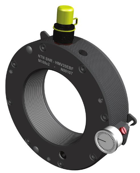
5 2. PRODUCT DESCRIPTION The hydraulic nut HMV..EBF is a tool that has been designed to permit the simple mounting and dismounting of rolling bearings with tapered bores. The parts to be installed can be moved into the desired position safely and without excessive use of force. Main area of application Mounting of rolling bearings (bore taper 1:12 / 1:30) on tapered shafts, adapter sleeves or withdrawal sleeves COMPONENT PARTS The hydraulic nut mainly consists of the ring body and ring piston. The ring body has an internal thread that is used to screw it onto a shaft or sleeve thread. Hydraulic oil under pressure is used to operate the piston Two O-rings are used to seal the piston. Hydraulic connection with cap (quick-action coupling) Sealing ring O-ring (outside) O-ring (inside) OUTER SHELL Outer shell with cross-knurling Nut identification Ring piston Ring body Marking for max. permitted stroke Plastic screw M5 Set dial gauge with extension and holder Nut thread in the ring body Fine-pitch / trapezoidal thread Bolt with pressure spring FACE SIDE Sealing plug with ball 5
. A fast-action coupling (Item 2) is screwed into the threaded hole in the outer shell.")
 can also be used for easy turning of the nut.")
6 One G1/4 threaded hole is provided in the end face as well as in the outer shell to connect a hydraulic pipe. The threaded hole in the end face is closed at the factory with a sealing plug with ball (Item 1). A fast-action coupling (Item 2) is screwed into the threaded hole in the outer shell. Cross-knurling is provided on the outer shell on the hydraulic nut to make it easier to screw it onto a shaft or sleeve thread. Optional connection at: Face side or Outer shell Toy bar The attached, standard mounting lever (Item 6) can also be used for easy turning of the nut. It is an installation aid and is pushed into the blind holes in the outer shell. Bolts with pressure springs (Item 10) are circumferentially mounted within the hydraulic nut. They ensure that the piston returns and helps to return the oil into the reservoir of the pump. The piston does not need to be pushed back manually. 6

 (blanked")


7 2.2. CONNECTIONS Connection for hydraulic pipe G1/4 (outer shell) Fast-action coupling installed in factory Threaded holes for removing the piston (to allow replacement of the O-rings) Blind holes for mounting lever 2x Ø 11 Bracket to allow fitting of Dial Gauge Eye bolt Connection for hydraulic pipe G1/4 (end face) (blanked off) Hydraulic nuts from size HMV60EBF onwards are equipped with additional threaded holes in the outer shell. The eye bolt included in the delivery can be installed there for better handling PRINCIPLE OF OPERATION Oil pressure inside the ring body is created by a hydraulic pump and causes the axial advance of the ring piston. This displacement pushes the rolling bearing onto its tapered seat. In order to ensure precise positioning of the rolling bearing, drive up distance should be checked by using a dial gauge. The ring piston is automatically pushed back to the starting position when the pump pressure is released. The oil automatically flows back into the reservoir of the pump. 7


8 3. SPARE PARTS, ACCESSORIES AND TECHNICAL DATA
9 3.1. HYDRAULIC NUT Pos Article Notice 1 TOOL HMV BALL PLUG 1/4 Sealing plug with ball * 2 TOOL HMV NIPPLE 1/4 Hydraulic connection * 3 TOOL HMV SW 1/4 Sealing ring for hydraulic connection * Consisting of: 1x quick-action coupling with cover 1x adapter thread 1x sealing ring 4 TOOL HMV PAS M5 Plastic set screw for dial gauge locking * 5 TOOL HMV DG HOLDER Dial gauge holder * 6 TOOL HMV TBAR 11x150 TOOL HMV TBAR 16x200 Toy bar * Consisting of: 1x M5 plastic set screw 1x M5 Knurled head screw 1x Holder with centre pin HMV10EBF - HMV58EBF: 11x150 HMV60EBF - HMV200EBF: 16x200 7 TOOL HMV EBO M12 TOOL HMV EBO M16 Eye bolt DIN 580 HMV60EBF - HMV130EBF: M12 HMV134EBF - HMV200EBF: M16 8 TOOL HMV... PISTON SEALS Set of piston seals Consisting of: 1x O-ring (inside) 1x O-ring (outside) 9 TOOL HMV... SET-PSK Set of pressure springs * Parts included in delivery 9
10 3.2. ACCESSORIES Order Number TOOL PUMP SET 700B-0.3L / Pump with accessories Description Hydraulic pump with 0.3 l oil volume Incl. hydraulic hose, connection nipple, pressure gauge (analogue), 0.3 l pre-filled with hydraulic oil max. working pressure 700 bar TOOL PUMP SET 700B-0.9L / Pump with accessories Hydraulic pump with 0.9 l oil volume Incl. hydraulic hose, connection nipple, pressure gauge (analogue), 0.9 pre-filled with hydraulic oil max. working pressure 700 bar TOOL PUMP SET 1500B-2.5L / Pump with accessories Pump with accessorieshydraulic pump with 2.55 l oil volume Incl. hydraulic hose, connection nipple, pressure gauge (analogue), 2.55 l pre-filled with hydraulic oil max. working pressure 1,500 bar TOOL PUMP GAUGE 700 TOOL HYDRAULIC OIL 1L Gauge up to max. 700 bar (analogue) Hydraulic fluid 1.0 l TOOL FEELER GAUGES 100 TOOL FEELER GAUGES 150 TOOL FEELER GAUGES 300 Feeler gauge (length 100 ) Feeler gauge (length 150 ) Feeler gauge (length 300 ) TOOL DIAL GAUGE 050 Dial gauge for a displacement distance up to 5 TOOL DIAL GAUGE 100 Dial gauge for a displacement distance up to 10 TOOL DIAL EXTENSION SET Extension adapter set for dial gauge 10
11 3.3. TECHNICAL DATA HMV..EBF Nut thread Required pumpvolume for hydraulic nuts HMV 10 EBF to HMV 40 EBF HMV 41 EBF to HMV 200 EBF HMV 10 EBF to HMV 54 EBF HMV 56 EBF to HMV 92 EBF HMV 94 EBF to HMV 200 EBF ISO 965/III-1980, Tolerance class 6H ISO , Tolerance class 7H TOOL PUMP SET 700B-0,3L TOOL PUMP SET 700B-0,9L TOOL PUMP SET 1500B-2,5L Thread size of eye bolt Fastening torque Sealing plug with ball HMV 60 EBF to HMV 130 EBF > HMV 130 EBF M12 M16 45 Nm Max. permitted operating pressure* at max. piston stroke HMV 10 EBF to HMV 25 EBF HMV 26 EBF to HMV 40 EBF HMV 41 EBF to HMV 60 EBF HMV 62 EBF to HMV 100 EBF HMV 102 EBF to HMV 120 EBF HMV 126 EBF to HMV 160 EBF HMV 170 EBF to HMV 200 EBF 700 bar 550 bar 450 bar 400 bar 350 bar 300 bar 250 bar * The required operating pressure for mounting and dismounting of rolling bearings is depending on various factors such as size of the bearing, bearing seat quality, numbers of contact surfaces as well as the weight of the rolling bearing. 11
12 4. PROCEDURE FOR THE MOUNTING OF ROLLER BEARINGS Push the bearing by hand as far as possible onto the tapered seat and screw the hydraulic nut onto the thread of the shaft or the sleeve. Ensure that the inner and outer threads are aligned with each other when positioning the nut. It is recoended to use an assembly paste. The start of the thread is marked on the outer shell of the ring body to ease the positioning of larger hydraulic nuts (from HMV90EBF onwards). Caution: Damage due to cross threading must be avoided BLEEDING OF THE HYDRAULIC SYSTEM Note: The hydraulic system must be bled when the nut is used for the first time and after each deinstallation of a hydraulic connection. Screw the whole thread length of the hydraulic nut onto the shaft or sleeve thread and connect the hydraulic pipe to the appropriate hydraulic connection (Item 2). Turn the sealing plug with ball (Item 1) to the highest position and loosen it slightly. Then pump oil, using the hydraulic pump, until the oil exits without bubbles. Thereafter, firmly close the sealing plug (max. fastening torque 45 Nm) USE Screw the hydraulic nut against the rolling bearing until the full annular piston bears evenly on the bearing. The piston must be in its start position and must be fully inserted in the annular body. To absorb the forces that arise during the displacement operation via the thread, a minimum overlap with the mating thread of at least 85% must be guaranteed. Thereafter, connect the hydraulic pipe to the appropriate hydraulic connection. 12
13 5. POSSIBLE MOUNTING / DISMOUNTING SITUATIONS FOR BEARINGS WITH SPHERICAL BORE Mounting Mounting a rolling bearing on an adapter sleeve on a cylindrical shaft. The rolling bearing is supported against a stop ring or shaft shoulder. Mounting a bearing on a withdrawal sleeve on a cylindrical shaft with thread. Bearing supported against a stop ring or shaft shoulder. Mounting a bearing on an adapter sleeve on cylindrical shaft. Mounting a bearing on tapered shaft seat Dismounting Dismounting a rolling bearing on a withdrawal sleeve. The hydraulic nut is acting against the inner ring. Dismounting a rolling bearing on a adapter sleeve. The hydraulic nut is acting against a nut mounted on the shaft. 13
 can be installed on the face side of the ring body. (The holder is included to the scope of delivery) 5.1.2.")
14 5.1. POSITIONING / AXIAL DISPLACEMENT Use of a dial gauge Part number 4 Part number 5 For the mounting process of a roller bearing a dial gauge can be used for measuring the axial displacement. Therefore a dial gauge holder (item 5) can be installed on the face side of the ring body. (The holder is included to the scope of delivery) Mounting the dial gauge with holder The dial gauge holder (item 5) is to be installed only when the HMV is screwed on the thread and the ring piston rests fully against the bearing. This is to prevent injury while turning the nut and to avoid damage to the sensitive dial gauge. The dial gauge holder is mounted radially with the cap head screw (M5) in one of the three possible positions on the ring body. The dowel pin in the holder helps to locate its position. Insert the dial gauge with the extension into the bore of the holder until the tip of the extension contacts the measurement surface ppropriate of the ring piston. Lock the dial gauge with the plastic screw (M5) (Item 4) so that it cannot slide. Turn the adjustment ring of the dial gauge to the zero position set and establish what axial displacement is required for the bearing to be fitted. Note The axial displacement depends on the clearance group and the size of the roller bearing. The values for spherical roller-bearings are provided in the table shown in chapter 8. Hydraulic oil is now pumped into the hydraulic nut using a hand pump. The ring piston moves the roller bearing onto the sleeve or the tapered bearing seat. The pumping process is to be continued until the prescribed displacement has been reached. It is recoended to make a final inspection of the internal clearance in the mounted position after the pressure has been released using feeler gauges. CAUTION! A circumferential, yellow marking on the ring piston shows that the maximum permitted stroke has been reached. As soon as this marker is aligned with the edge of the ring body, the ring piston may not be pumped out of the ring body any further (risk of injury / damage to the hydraulic nut) Open the pressure release valve to allow the removal of the nut. The annular piston automatically travels back to its starting position on the hand pump and presses the hydraulic oil out of the hydraulic nut and into the pump as it does so. The hydraulic nut can now be dismounted. The press-fitted assembly must now be fastened with a lock nut and a lock washer. 14
15 6. SERVICING AND MAINTENANCE Dirt and oil residues must be removed from the surfaces after every use to ensure flawless and safe functioning of the hydraulic nut and the hydraulic components. Hydraulic connections and threads must be checked for possible damage. The hydraulic connections must be safely capped with covers after use and protected against the penetration of dirt. Make sure that the employed hydraulic oil is clean and complies with the required specifications (ISO 11158). The pump tank must always be filled with sufficient oil. If hydraulic oil emerges from the hydraulic nut during use, the O- rings may be defective (or the maximum stroke of the nut has been reached check if yellow mark is visible). For replacement of the O- rings, please return the hydraulic nut to NTN-SNR. For further information, please contact NTN-SNR. 7. MEASUREMENT TABLE 15
16 Size Thread External diameter Total width Piston diameter Permitted piston stroke Flange width Body width Diameter Piston surface area ² Weight kg G D B max. d2 B1 B2 d1 HMV 10 EBF M 50x1, ,8 HMV 11 EBF M 55x ,1 HMV 12 EBF M 60x ,3 HMV 13 EBF M 65x ,4 HMV 14 EBF M 70x ,6 HMV 15 EBF M 75x ,8 HMV 16 EBF M 80x ,9 HMV 17 EBF M 85x ,1 HMV 18 EBF M 90x ,3 HMV 19 EBF M 95x ,5 HMV 20 EBF M 100x ,7 HMV 21 EBF M 105x ,0 HMV 22 EBF M 110x ,3 HMV 23 EBF M 115x ,4 HMV 24 EBF M 120x ,6 HMV 25 EBF M 125x ,7 HMV 26 EBF M 130x ,0 HMV 27 EBF M 135x ,3 HMV 28 EBF M 140x ,5 HMV 29 EBF M 145x ,9 HMV 30 EBF M 150x ,3 HMV 31 EBF M 155x ,7 HMV 32 EBF M 160x ,2 HMV 33 EBF M 165x ,5 HMV 34 EBF M 170x ,0 HMV 36 EBF M 180x ,8 HMV 38 EBF M 190x ,3 HMV 40 EBF M 200x ,4 HMV 41 EBF Tr 205x ,8 HMV 42 EBF Tr 210x ,6 HMV 43 EBF Tr 215x ,0 HMV 44 EBF Tr 220x ,5 HMV 45 EBF Tr 225x ,2 HMV 46 EBF Tr 230x ,7 HMV 47 EBF Tr 235x ,8 HMV 48 EBF Tr 240x ,2 HMV 50 EBF Tr 250x ,2 HMV 52 EBF Tr 260x ,2 HMV 54 EBF Tr 270x ,7 HMV 56 EBF Tr 280x ,3 HMV 58 EBF Tr 290x ,0 HMV 60 EBF Tr 300x ,2 16
17 Size Thread External diameter Total width Piston diameter Permitted piston stroke Flange width Body width Diameter Piston surface area ² Weight kg G D B max. d2 B1 B2 d1 HMV 62 EBF Tr 310x ,9 HMV 64 EBF Tr 320x ,1 HMV 66 EBF Tr 330x ,0 HMV 68 EBF Tr 340x ,4 HMV 69 EBF Tr 345x ,5 HMV 70 EBF Tr 350x ,8 HMV 72 EBF Tr 360x ,7 HMV 73 EBF Tr 365x ,4 HMV 74 EBF Tr 370x ,9 HMV 76 EBF Tr 380x ,6 HMV 77 EBF Tr 385x ,1 HMV 80 EBF Tr 400x ,8 HMV 82 EBF Tr 410x ,0 HMV 84 EBF Tr 420x ,9 HMV 86 EBF Tr 430x ,9 HMV 88 EBF Tr 440x ,8 HMV 90 EBF Tr 450x ,3 HMV 92 EBF Tr 460x ,3 HMV 94 EBF Tr 470x ,4 HMV 96 EBF Tr 480x ,7 HMV 98 EBF Tr 490x ,9 HMV 100 EBF Tr 500x ,4 HMV 102 EBF Tr 510x ,7 HMV 104 EBF Tr 520x ,3 HMV 106 EBF Tr 530x ,4 HMV 108 EBF Tr 540x ,9 HMV 110 EBF Tr 550x ,0 HMV 112 EBF Tr 560x ,3 HMV 114 EBF Tr 570x ,2 HMV 116 EBF Tr 580x ,8 HMV 120 EBF Tr 600x ,1 HMV 126 EBF Tr 630x ,8 HMV 130 EBF Tr 650x ,7 HMV 134 EBF Tr 670x ,6 HMV 138 EBF Tr 690x ,2 HMV 142 EBF Tr 710x ,9 HMV 150 EBF Tr 750x ,4 HMV 160 EBF Tr 800x ,6 HMV 170 EBF Tr 850x ,2 HMV 180 EBF Tr 900x ,5 HMV 190 EBF Tr 950x ,0 HMV 200 EBF Tr 1000x ,0 17
18 NTN-SNR HYDRAULIC NUT HMVC..EBF Size Thread Numbers of thread Outside diameter Total width Piston diameter Permitted piston stroke inch Flange width Body width Diameter Piston surface area inch² Weight inch inch inch inch inch inch inch Kg HMVC EBF G D B max. d2 B1 B2 d1 10 1, ,5 1,7 4,4 0,20 0,20 1,5 2,0 4,4 6,3 11 2, ,7 1,7 4,6 0,20 0,20 1,5 2,2 4,8 6,8 12 2, ,9 1,7 4,8 0,20 0,20 1,5 2,4 5,1 7,2 13 2, ,1 1,7 5,0 0,20 0,20 1,5 2,6 5,4 7,6 14 2, ,3 1,7 5,2 0,20 0,20 1,5 2,8 5,8 7,9 15 2, ,5 1,7 5,4 0,20 0,20 1,5 3,0 6,1 8,3 16 3, ,7 1,7 5,6 0,20 0,20 1,5 3,2 6,4 8,7 17 3, ,9 1,7 5,8 0,20 0,20 1,5 3,4 6,7 9,1 18 3, ,1 1,7 6,0 0,20 0,20 1,5 3,6 6,8 9,5 19 3, ,4 1,7 6,2 0,20 0,20 1,5 3,8 7,5 10,0 20 3, ,5 1,7 6,4 0,20 0,24 1,5 4,0 7,5 10,4 21 4, ,8 1,7 6,6 0,20 0,24 1,5 4,2 8,1 11,0 22 4, ,0 1,7 6,9 0,20 0,24 1,5 4,4 8,8 11,6 24 4, ,4 1,7 7,2 0,20 0,24 1,5 4,8 9,4 12,4 26 5, ,8 1,7 7,6 0,20 0,24 1,5 5,2 10,1 13,2 28 5, ,2 1,8 8,0 0,20 0,28 1,5 5,6 10,7 14,3 30 5, ,7 1,8 8,5 0,20 0,28 1,5 6,0 12,3 16,0 32 6, ,1 1,9 9,0 0,24 0,28 1,6 6,4 14,0 18,0 34 6, ,6 1,9 9,4 0,24 0,28 1,6 6,8 15,8 19,9 36 7, ,1 1,9 9,9 0,24 0,28 1,6 7,2 17,7 21,5 38 7, ,6 2,0 10,5 0,28 0,31 1,7 7,6 18,5 24,9 40 7, ,1 2,0 10,9 0,31 0,31 1,7 8,0 19,4 27,3 44 8, ,0 2,0 11,9 0,31 0,31 1,7 8,8 21,1 31,9 46 9, ,5 2,1 12,4 0,31 0,31 1,8 9,2 21,9 34,7 48 9, ,0 2,2 12,8 0,35 0,35 1,8 9,6 25,4 37, , ,0 2,2 13,9 0,35 0,35 1,9 10,4 27,2 44, , ,0 2,3 14,8 0,39 0,35 1,9 11,2 30,7 51, , ,1 2,4 16,0 0,39 0,39 2,0 12,0 37,0 64, , ,9 2,5 16,8 0,43 0,39 2,1 12,8 39,2 70, , ,7 2,5 17,6 0,47 0,39 2,1 13,5 41,4 75, , ,9 2,6 18,7 0,51 0,39 2,2 14,3 51,8 89, , ,7 2,7 19,5 0,55 0,43 2,3 15,1 54,4 98, , ,9 2,8 20,7 0,55 0,43 2,4 15,9 54,8 116, , ,9 2,8 21,7 0,55 0,43 2,4 16,7 60,8 127, , ,6 2,9 22,5 0,55 0,43 2,4 17,5 63,4 134, , ,6 3,0 23,5 0,59 0,47 2,5 18,3 71,3 150, , ,4 3,0 24,3 0,63 0,47 2,6 19,1 78,2 158, , ,6 3,1 25,4 0,63 0,47 2,6 19,8 85,7 181, , ,8 3,2 26,6 0,67 0,51 2,7 21,0 78,3 199, , ,1 3,3 28,0 0,71 0,51 2,8 22,2 87,0 221, , ,9 3,4 29,8 0,75 0,51 2,9 23,8 101,0 249, , ,1 3,5 30,9 0,75 0,55 2,9 25,0 105,6 266, , ,1 3,5 32,9 0,87 0,55 3,0 26,5 125,3 307, , ,6 3,7 34,5 0,91 0,59 3,1 28,1 132,1 337, , ,2 3,7 36,1 0,91 0,59 3,1 29,7 138,9 358, , ,2 3,8 38,0 0,98 0,63 3,1 31,7 147,4 387, , ,6 3,9 40,4 1,02 0,63 3,3 33,6 179,2 448, , ,3 4,1 43,1 1,10 0,67 3,4 35,6 238,6 545, , ,3 4,1 45,1 1,10 0,67 3,4 37,6 250,8 575,3 18
19 8. TABLE FOR RADIAL CLEARANCE REDUCTION / AXIAL DISPLACEMENT Nominal dimensions Radial clearance before mounting of bearing and clearance group bore Reduction of radial clearance Displacement on taper 1 : 12 Displacement on taper 1 : 30 Check value for minimum radial clearance after mounting normal C3 C4 Shaft Sleeve Shaft Sleeve Air unit above to min max min max min max min max min max min max min max min max normal C3 C ,035 0,05 0,05 0,065 0,065 0,085 0,02 0,025 0,35 0,4 0,35 0,45 0,015 0,025 0, ,045 0,06 0,06 0,08 0,8 0,1 0,025 0,03 0,4 0,45 0,45 0,5 0,02 0,03 0, ,055 0,075 0,075 0,095 0,095 0,12 0,03 0,04 0,45 0,6 0,5 0,7 0,025 0,035 0, ,07 0,095 0,095 0,12 0,12 0,15 0,04 0,05 0,6 0,75 0,7 0,85 0,025 0,04 0, ,08 0,11 0,11 0,14 0,14 0,18 0,045 0,06 0,7 0,9 0,75 1 1,7 2,2 1,8 2,4 0,035 0,05 0, ,1 0,135 0,135 0,17 0,17 0,22 0,05 0,07 0,7 1,1 0,8 1,2 1,9 2,7 2 2,8 0,05 0,065 0, ,12 0,16 0,16 0,2 0,2 0,26 0,065 0,09 1,1 1,4 1,2 1,5 2,7 3,5 2,8 3,6 0,055 0,08 0, ,13 0,18 0,18 0,23 0,23 0,3 0,075 0,1 1,2 1,6 1,3 1, ,1 4,2 0,055 0,09 0, ,14 0,2 0,2 0,26 0,26 0,34 0,08 0,11 1,3 1,7 1,4 1,9 3,2 4,2 3,3 4,6 0,06 0,1 0, ,16 0,22 0,22 0,29 0,29 0,37 0,09 0,13 1,4 2 1,5 2,2 3,5 4,5 3,6 5 0,07 0,1 0, ,18 0,25 0,25 0,32 0,32 0,41 0,1 0,14 1,6 2,2 1,7 2,4 4 5,5 4,2 5,7 0,08 0,12 0, ,2 0,27 0,27 0,35 0,35 0,45 0,11 0,15 1,7 2,4 1,8 2,6 4,2 6 4,6 6,2 0,09 0,13 0, ,22 0,3 0,3 0,39 0,39 0,49 0,12 0,17 1,9 2,6 2 2,9 4,7 6,7 4,8 6,9 0,1 0,14 0, ,24 0,33 0,33 0,43 0,43 0,54 0,13 0, ,2 3,2 5 7,5 5,2 7,7 0,11 0,15 0, ,27 0,36 0,36 0,47 0,47 0,59 0,15 0,21 2,4 3,4 2,6 3,6 6 8,2 6,2 8,4 0,12 0,17 0, ,3 0,4 0,4 0,52 0,52 0,65 0,17 0,23 2,6 3,6 2,9 3,9 6,5 9 6,8 9,2 0,13 0,19 0, ,33 0,44 0,44 0,57 0,57 0,72 0,2 0,26 3,1 4,1 3,4 4,4 7, ,4 0,13 0,2 0, ,37 0,49 0,49 0,63 0,63 0,79 0,21 0,28 3,3 4,4 3,6 4,8 8,2 11 8,4 11,2 0,16 0,23 0, ,41 0,54 0,54 0,68 0,68 0,87 0,24 0,32 3,7 5 4,1 5,4 9,2 12,5 9,6 12,8 0,17 0,25 0, ,46 0,6 0,6 0,76 0,76 0,98 0,26 0,35 4 5,4 4,4 5, ,5 10,4 14 0,2 0,29 0, ,51 0,67 0,67 0,85 0,85 1,09 0,3 0,4 4,6 6,2 5,1 6,8 11,5 15, ,21 0,31 0, ,57 0,75 0,75 0,96 0,96 1,22 0,34 0,45 5,3 7 5,8 7,6 13,3 17,5 13,6 18 0,23 0,35 0, ,64 0,84 0,84 1,07 1,07 1,37 0,37 0,5 5,7 7,8 6,3 8,5 14,3 19,5 14,8 20 0,27 0,39 0, ,71 0,93 0,93 1,19 1,19 1,52 0,41 0,55 6,3 8,5 7 9,4 15, ,4 22 0,3 0,43 0, ,78 1,02 1,02 1,3 1,3 1,65 0,45 0,6 6,8 9 7,6 10, ,32 0,48 0, ,86 1,12 1,12 1,42 1,42 1,8 0,49 0,65 7,4 9,8 8, , ,6 26 0,34 0,54 0,77 Push the rolling bearing onto the taper bearing seat and manually screw the hydraulic nut onto the thread of the shaft or sleeve until it is in full contact with the bearing. The hydraulic nut is in the starting position. Connect the hydraulic pump to the hydraulic nut and push the rolling bearing into its mounted position by means of hydraulic pressure. After the correct axial displacement has been achieved, the hydraulic pressure should be released allowing the piston to return. The internal clearance should then be checked with feeler gauges. 19
20 9. SELECTION TABLE FOR HYDRAULIC NUT 9.1. FOR DISMOUNTING / MOUNTING WITH WITHDRAWAL SLEEVE HMV.. EBF Thread Hydraulic Nut Shaft-Ø Bearing Bore WITHDRAWAL SLEEVE Size 10 M50x1, AH2309 AH M55x AHX2310 AHX M60x AH2310 AH M60x AHX2311 AHX M65x AH2311 AH M65x AHX2312 AHX M70x AH2312 AH M70x AH2313G AH313G 15 M75x AH2313 AH M75x AHX2314G AH314G 16 M80x AHX2314 AH M80x AHX2315G AH315G 17 M85x AH M85x AHX2315 AH M90x AH M90x AHX2316 AH M95x AH M95x AHX2317 AHX M100x AH2317 AH M100x AHX2318 AHX318 AHX M105x AH2318 AH M105x AHX2319 AHX M110x AH2319 AH M110x AHX2320 AHX320 AHX3120 AHX M115x AH M115x AH M120x AH M120x AHX2322G AHX3122 AHX3222G 25 M125x AH M125x AHX2322 AHX M125x AH M130x AH2322 AH M130x AH M130x AHX2324G AH24124 AHX3024 AHX3124 AHX3224G 27 M135x AHX2324 AHX M135x AH M140x AH2324 AH M140x AH M140x AHX2326G AH24126 AHX3026 AHX3126 AHX3226G 29 M145x AHX2326 AHX M145x AH M150x AH2326 AH M150x AH
21 HMV.. EBF Thread Hydraulic Nut Shaft-Ø Bearing Bore WITHDRAWAL SLEEVE Size 30 M150x AHX2328G AH24128 AHX3028 AHX3128 AHX3228G 31 M155x AHX2328 AHX M155x AH M160x AH2328 AH M160x AH M160x AHX2330G AH24130 AHX3030 AHX3130G AHX3230G 33 M165x AHX2330 AHX3130 AHX M170x AH2330 AH M170x AH2332G AH24032 AH24132 AH3032 AH3132G AH3232G 36 M180x AH2332 AH3132 AH M180x AH2334G AH24034 AH24134 AH3034 AH3134G AH3234G 38 M190x AH2334 AH3134 AH M190x AH2236G AH2336G AHX2336G AH24036 AH24136 AH3036 AH3136G AH3236G 40 M200x AH2236 AH2336 AH3136 AH M200x AH2238G AH2338G AH24038 AH24138 AH3038G AH3138G AH3238G 41 Tr205x AH Tr210x AH2238 AH2338 AH3138 AH Tr210x AH24040 AH24140 AH3040G 43 Tr215x AH Tr220x AH2240 AH2340 AH3140 AH Tr230x AOH24044 AOH24144 AH3044G AOH3044G 47 Tr235x AH3044 AOH Tr240x AH2244 AOH2244 AH2344 AOH2344 AH3144 AOH Tr250x AOH Tr260x AH2248 AOH2248 AH2348 AOH2348 AOH24148 AH3048 AOH3048 AH3148 AOH Tr270x AOH Tr280x AH2252G AOH2252G AH2352G AOH2352G AOH24052G AOH24152 AH3052 AOH3052 AH3152G AOH3152G 58 Tr290x AH2252 AOH2252 AH2352 AOH2352 AH3152 AOH Tr290x AOH Tr300x AH2256G AOH2256G AH2356G AOH2356G AOH24056G AOH24156 AH3056 AOH3056 AH3156G AOH3156G 62 Tr310x AH2256 AOH2256 AH2356 AOH2356 AH3156 AOH Tr310x AOH Tr320x AH2260G AOH2260G AOH24060G AOH24160 AH3060 AOH3060 AH3160G AOH3160G AH3260G AOH3260G 66 Tr330x AH2260 AOH2260 AH3160 AOH3160 AH3260 AOH Tr330x AOH Tr340x AH2264G AOH2264G AOH24064G AOH24164 AH3064G AOH3064G AH3164G AOH3164G AH3264G AOH3264G 69 Tr345x AH3064 AOH Tr350x AH2264 AOH2264 AH3164 AOH3164 AH3264 AOH Tr360x AOH24068 AOH24168 AH3068G AOH3068G AH3168G AOH3168G AH3268G AOH3268G 73 Tr365x AH3068 AOH Tr370x AH3168 AOH3168 AH3268 AOH Tr380x AOH24072 AOH24172 AH3072G AOH3072G AH3172G AOH3172G AH3272G AOH3272G 77 Tr385x AH3072 AOH
22 9.2. FOR DISMOUNTING / MOUNTING WITH ADAPTER SLEEVE HMV.. EBF Thread Hydraulic Nut Saft-Ø Bearing Bore ADAPTER SLEEVE Size [H200] [H300] [H2300] [H3900] 10 M50x1, H210 H310 H M55x H211 H311 H M60x H212 H312 H M65x H213 H313 H M70x H214 H314 H M75x H215 H315 H M80x H216 H316 H M90x H218 H318 H M95x H219 H319 H M100x H220 H320 H2320 H M105x H221 H321 H M110x H222 H322 H2322 H M120x H2324 H3024 H M130x H2326 H3026 H M140x H2328 H3028 H M150x H2330 H3030 H M160x H2332 H3032 H M180x H2334 H3034 H M180x H2336 H3936 H3036 H M190x H2338 H3938 H3038 H Tr240x H2348 H3948 H3048 H Tr280x H2356 H3956 H3056 H Tr300x H3960 H3060 H3160 H Tr320x H3964 H3064 H3164 H Tr360x H3972 H3072 H3172 H Tr380x H3976 H3076 H3176 H Tr400x H3980 H3080 H3180 H Tr420x H3984 H3084 H3184 H Tr440x H3988 H3088 H3188 H Tr460x H3992 H3092 H3192 H Tr480x H3996 H3096 H3196 H Tr500x H39/500 H30/500 H31/500 H32/ Tr530x H39/530 H30/530 H31/530 H32/ Tr560x H39/560 H30/560 H31/560 H32/ Tr600x H39/600 H30/600 H31/600 H32/ Tr630x H39/630 H30/630 H31/630 H32/ Tr670x H39/670 H30/670 H31/670 H32/ Tr750x H39/750 H30/750 H31/750 H32/ Tr800x H39/800 H30/800 H31/800 H32/ Tr850x H30/850 H31/ Tr900x H30/900 H31/ Tr950x Tr1000x H30/950 H31/950 H30/1000H31/1000 [H3000] [H3100] [H3200] [H39] [H30] [H31] [H32] 22
23 NOTE 23


24 HYDRAULIC NUT HMV..EBF DOC.I_HMV EBF.MANUAL.ARG1.GBa - Non contractual document - NTN-SNR Copyright International 02/2017 Printed in France - Photos : Pedro Studio Photo NTN-SNR ROULEMENTS - 1 rue des Usines Annecy RCS ANNECY B Code APE 2815Z - Code NACE
NTN-SNR HYDRAULIC NUT HMV..EBF OPERATING INSTRUCTIONS
 OPERATING INSTRUCTIONS Copyright NTN-SNR HMV_TS 1964gb1.04 TABLE OF CONTENTS 1. Safety Instructions... 2 2. Product Description... 3 2.1. Structure and equipment... 3 2.2. Connections / Bores... 4 2.3.
Sleeves and accessories
 Sleeves 392 Definition 392 Series 392 Variants 392 Fitting and removal criteria 392 Suffixes 395 Characteristics 396 Adapter sleeves (mm) 396 Adapter sleeves (inch) 399 Withdrawal sleeves 400 Nuts and
VIBRATING SCREEN APPLICATIONS EF800 ULTAGE. Spherical roller bearings. With You
 VIBRATING SCREEN APPLICATIONS EF800 ULTAGE Spherical roller bearings With You OPTIMIZE THE EFFICIENCY OF YOUR SCREENS THE FEATURES THAT MAKE THE EF800 OPTIMISED MASSIVE BRASS CAGE: PROVEN RELIABILITY The
FAG HYDRAULIC NUTS. FAG OEM und Handel AG
 FAG HYDRAULIC NUTS FAG OEM und Handel AG CONTENTS Application Design Principle Design Variations Pressure Generators, Connection Pieces Dimensional Tables for FAG Hydraulic Nuts (Metric) Dimensional Tables
FAG Hydraulic nuts. Technical Product Information
 FAG Hydraulic nuts Technical Product Information Contents Application 2 Design 2 Design variants 3 Pressure generators, connectors 4 Dimension tables for FAG hydraulic nuts (metric) 6 Dimension tables
TIMING AND ACCESSORY Ranges. Diagnostic Expert Analysis & Recommendations
 Diagnostic Expert Analysis & Recommendations MAJOR CAUSES OF TIMING BELT FAILURES: 1 Uneven breakage 2 A clean break 3 Detached or separation of the belt teeth 4 Ripped teeth 5 Split teeth 6 Loss of teeth
16 Bearing accessories
 Rolling bearings 16 Bearing accessories Adapter sleeves... 1270 Designs and variants... 1270 Basic design... 1270 Variants for oil injection... 1270 Variants for CARB toroidal roller bearings... 1273
DIAGNOSTIC EXPERT. Analysis & Recommendations. Wheel Bearing. With You
 Wheel Bearing Range DIAGNOSTIC EXPERT Analysis & Recommendations www.ntn-snr.com Main causes of failure Most failures are detected by noise; however, there are many causes 1 Indentations or breakage of
Instructions for Assembling and Disassembling Sleeves under Self-aligning Bearings with Tapered Bore
 Sleeve for Bearings Instructions for Assembling and Disassembling Sleeves under Self-aligning Bearings with Tapered Bore BGL Application Engineering See the step-by-step procedure at www.bgl.com.br/en/treinamento.htm
VARIATIONS IN EQUIPMENT HOW TO SELECT EXAMPLE FOR ORDERING TYPE
 VARIATIONS IN EQUIPMENT Material Stainless and acidproof steel Aluminium alloys Various combinations of material Seals for elevated temperatures Surface finish Lacquered Chemi-nickel coating On customer's
POLIPUMP YOUR OWN CENTRALISED LUBRICATION SYSTEM IN JUST A FEW QUICK STEPS. Easy set up, economical and powerful
 POLIPUMP YOUR OWN CENTRALISED LUBRICATION SYSTEM IN JUST A FEW QUICK STEPS Easy set up, economical and powerful Set up your own multipoint lubrication in only 4 steps From 1 to 35 points to lubricate up
TECHNICAL INFORMATION
 Radial Roller Bearings Fitting and Mounting Fixed Bearings and Float Bearings Radial and axial loads in bearing units can be transmitted by fixed and floating bearings A fixed bearing is generally used
Double-row ball bearings
 Double-row ball bearings Radial double-row ball bearings 262 Definition and capabilities 262 Series 262 Tolerances and clearances 262 Design criteria 263 Suffixes 263 Characteristics 264 Radial double-row
Installation and Maintenance Instructions JSE MAEAD Extruder Clutch. World Leader in Modular Torque Limiters
 World Leader in Modular Torque Limiters Installation and Maintenance Instructions JSE.5-0104MAEAD Extruder Clutch 1304 Twin Oaks Street Wichita Falls, Texas 76302 (940) 723-7800 Fax: (940) 723-7888 E-mail:
Installation and Operational Instructions for EAS - HTL housed overload clutch Sizes 01 3 Type 490._24.0
 Please read these Operational Instructions carefully and follow them accordingly! Ignoring these Instructions may lead to malfunctions or to clutch failure, resulting in damage to other parts. Contents:
Installation and Maintenance Instructions JSE1-0128MAEAD Extruder Clutch. World Leader in Modular Torque Limiters
 World Leader in Modular Torque Limiters Installation and Maintenance Instructions JSE1-0128MAEAD Extruder Clutch 1304 Twin Oaks Street Wichita Falls, Texas 76302 (940) 723-7800 Fax: (940) 723-7888 E-mail:
3. BEARING ARRANGEMENT DESIGN
 3. BEARING ARRANGEMENT DESIGN 3.1 GENERAL PRINCIPLES OF ROLLING BEARING ARRANGEMENT DESIGN Rotating shaft or another component arranged in rolling bearings is guided by them in radial as well as in axial
Technical Information
 Technical Information TI No. WL 80-48 E April 1999 Rolling Bearings FAG Mechanical Extractors Small rolling bearings with bore diameters of up to about 100 mm which have an interference fit on the shaft
Mechanical Sliding Caliper Disc Brake. Type PAN 19-1 Assembly and Maintenance Instructions
 WABCO Mannheim Mechanical Sliding Caliper Disc Brake Type PAN 19-1 Assembly and Maintenance Instructions WABCO Radbremsen GmbH Postfach 71 02 63 D-68222 Mannheim Bärlochweg 25 D-68229 Mannheim +49 (0)6
15. Bearing Handling Storage Fitting A-97
 15. Bearing Handling Bearings are precision parts, and in order to preserve their accuracy and reliability, care must be exercised in their handling. In particular, bearing cleanliness must be maintained,
Unique range of bearings for extreme use AFFORDABLE TECHNICAL - AVAILABLE - READY TO USE. With You
 Unique range of bearings for extreme use AFFORDABLE TECHNICAL - AVAILABLE - READY TO USE www.ntn-snr.com TOPLINE is constituted by deep groove ball bearings in series 6000, 6200 and 6300 which answer users
Standard Parts for Mould Making
 Standard Parts for Mould Making Index Your Production Partner 4-5 Guide Elements Locating units, round 8 Locating units, flat 8 Compensation Discs 9 Adjusting washers 9 Ejector rods 10 Centering sleeves
Mounting and dismounting
 Mounting and dismounting General information... 258 Where to mount... 258 Preparations for mounting and dismounting... 258 Bearing handling... 260 Mounting... 261 Mounting bearings with a cylindrical bore...
Bearing Handling. 15. Bearing Handling Bearing storage Installation
 15. Bearing Handling Bearings are precision parts and, in order to preserve their accuracy and reliability, care must be exercised in their handling. In particular, bearing cleanliness must be maintained,
Mounting rolling bearings
 Mounting rolling bearings Preparations prior to mounting... 46 Planning... 46 Cleanliness... 46 Removing the preservative from new bearings..................... 47 Checking associated components..... 47
Assembly Instructions
 Drive Technology \ Drive Automation \ System Integration \ Services *2450452_0617* Assembly Instructions Didactics - Gear Unit Technology Helical Gear Unit R57F AD2 Edition 06/2017 2450452/EN SEW-EURODRIVE
BoWex FLE-PA. BoWex FLE-PAC. KTR-N Sheet: Edition: EN 1 of BoWex FLE-PA / FLE-PAC Operating/Assembly instructions
 1 of 17 is a torsionally rigid flange coupling. It is able to compensate for shaft misalignment, for example caused by manufacturing inaccuracies, thermal expansion, etc. BoWex FLE-PA BoWex FLE-PAC Drawn:
Accessories, spare parts and measuring equipment
 Accessories, spare parts and measuring equipment The broad range of accessories, spare parts and measuring equipment represents a useful addition to the range of actual clamping tools and offers spare
SPEED & POSITION SENSOR SOLUTIONS. With You RUGGED - ACCESSIBILITY - COMPACTNESS - PRECISION
 SPEED & POSITION SOLUTIONS RUGGED - ACCESSIBILITY - COMPACTNESS - PRECISION www.ntn-snr.com With You NTN-SNR A LEADING PLAYER NTN Corporation is a world leader as designer, developer and manufacturer of
Installation and operating manual
 LK product no: 901002 and 901102 501002 and 501102 (JIS) Article no: 74500 Revision: 9 Article no: 74500 Revision: 9 2 (23) Contents 1. General information... 5 2. Safety precautions... 5 2.1 Significance
For advanced drive technology CLAMPEX. Shaft-hub-connection. KTR Precision joints CLAMPEX
 technology CLAMPEX Shaft-hub-connection CLAMPEX KTR Precision joints 227 technology Table of contents Page Brief information 228 Selection and calculation 25-255 CLAMPEX -Selection Shaft diameter = d 0
PAN 17 MECHANICAL SLIDING CALLIPER DISC BRAKE ASSEMBLY AND MAINTENANCE INSTRUCTIONS
 PAN 17 MECHANICAL SLIDING CALLIPER DISC BRAKE ASSEMBLY AND MAINTENANCE INSTRUCTIONS PAN 17 MECHANICAL SLIDING CALLIPER DISC BRAKE Assembly and Maintenance Instructions 2nd edition This publication is
Instruction Manual for HSPA Take-Up Units
 Installation Instruction Manual for HSPA Take-Up Units Warning: To ensure the drive is not unexpectedly started, turn off and lockout the power source before proceeding. Failure to observe these precautions
Instructions for Assembling and Disassembling Sleeves under Self-aligning Bearings with Tapered Bore
 Sleeve for Bearings Instructions for Assembling and Disassembling Sleeves under Self-aligning Bearings with Tapered Bore BGL Application Engineering See the step-by-step procedure at www.bgl.com.br/en/treinamento.htm
Clutch Repairs (465) Copyright GEDORE Automotive GmbH, Germany. formerly
 Copyright GEDORE Automotive GmbH, Germany. formerly") Copyright GEDORE Automotive GmbH, Germany (465) -01 KL-0500-45 KA Clutch Tool Set (SAC), in a Plastic Storage Case (Pat.) Suitable for Self-Adjusting Clutches (with 6 and 8 bolt holes); e.g. on VW-Audi,
Copyright GEDORE Automotive GmbH, Germany (465) -01 KL-0500-45 KA Clutch Tool Set (SAC), in a Plastic Storage Case (Pat.) Suitable for Self-Adjusting Clutches (with 6 and 8 bolt holes); e.g. on VW-Audi,
disc brake axle with WABCO calipers
 1 2 disc brake axle with WABCO calipers 3 4 disc brake axle with WABCO calipers 5 6 disc brake axle with WABCO calipers IMT axles are supplied as non-cambered and are within the limits of a 2 minute negative
Sisu S-Cam Drum Brakes
 Sisu S-Cam Drum Brakes (For hub reduction rear axles since 1992) Maintenance Manual Sisu Axles, Inc. Autotehtaantie 1 P.O. Box 189 FIN-13101 Hämeenlinna Finland Phone int + 358 204 55 2999 Fax int + 358
Boston Gear LOR Series
 Boston Gear LOR Series Trig-O-Matic Lite Overload Release Clutch Installation and Maintenance Instructions Doc. No. LOR Series Trig-O-Matic Lite www.bostongear.com LOR SERIES TRIG-O-MATIC LITE OVERLOAD
4 Self aligning ball bearings
 Rolling bearings 4 Self aligning ball bearings Designs and variants... 538 Basic design bearings... 539 Bearings with an extended inner ring.. 540 Cages... 540 Sealing solutions... 540 Greases for sealed
Installation Procedures
 For the precision ball and roller bearings supplied by MRC Bearings, skill and cleanliness while handling, mounting and dismounting are necessary to ensure satisfactory bearing performance. As precision
Installation and operating manual Quick closing valve (Bellow sealed) LK product no:
 LK product no:") LK product no: 902002 Article no: 74506 Revision: 2 Contents 1. General information... 3 2. Safety precautions... 3 2.1 Significance of symbols... 3 2.2 Explanatory notes on safety information... 3 3.
LK product no: 902002 Article no: 74506 Revision: 2 Contents 1. General information... 3 2. Safety precautions... 3 2.1 Significance of symbols... 3 2.2 Explanatory notes on safety information... 3 3.
CAUTION. Fuel Injection Pump, In-Line, Spill Port Timing
 Page 4 of 22 Rotate the crankshaft counterclockwise, as viewed from the front of the engine, to approximately 40 degrees before TDC. Both the RQV and RQV-K governor require the shutdown lever to be in
Vane pump, direct operated
 Vane pump, direct operated RE 1/8.8 Replaces: 1. 1/18 Type PV7 A Nominal sizes 1 to Series 1X / X Maximum operating pressure 1 bar Displacement volume 1 to cm 3 H17 H9 Overview of contents Features Contents
Dr. TRETTER AG. Tolerance Rings. safe cost-effective fast assembly
 Dr. TRETTER AG Tolerance Rings safe cost-effective fast assembly Tolerance Rings are corrugated metal strips manufactured of high quality spring steel. Tolerance Rings are a fastening device between two
EUGEN WOERNER GmbH & Co. KG Postfach 1661 DE Wertheim Am Eichamt 8 DE Wertheim. Pump unit GMZ-E
 Pump unit GMZ-E Pump used to supply oil and grease from a barrel directly through a lid-hole or a bunghole. Technical data: Pump with bung-hole Pump with barrel lid Delivery volume per stroke: Pump element
SAB 202 Screw compressor units. S pa re parts m an ual
 SAB 202 Screw compressor units S pa re parts m an ual en 1 Spare parts list for SAB 202 Pos Designation No Part no Complete compressor LF, aut Vi 4161059 Complete compressor LF, man Vi 4161060 Complete
Installation and Maintenance Instructions JSE2-0241MAEAD Extruder Clutch. World Leader in Modular Torque Limiters
 World Leader in Modular Torque Limiters Installation and Maintenance Instructions JSE2-0241MAEAD Extruder Clutch 1304 Twin Oaks Street Wichita Falls, Texas 76302 (940) 723-7800 Fax: (940) 723-7888 E-mail:
STANDARD PROGRAMME Hydraulic Chucks
 20 STANDARD PRORAMME STANDARD PRORAMME 23 Hydraulic Chuck ISO 7388-1, Form AD (prev. DIN 69871-AD), extra short design d 1 d 2 d 3 l3 ISO 7388-1 Form AD 3 µm h6 2.5 25000 min Nominal size SK/ISO Dimensions
MAXX TM 22T MECHANICAL SLIDING CALIPER DISC BRAKE INSTALLATION AND MAINTENANCE INSTRUCTIONS
 MAXX TM 22T MECHANICAL SLIDING CALIPER DISC BRAKE INSTALLATION AND MAINTENANCE INSTRUCTIONS MAXX TM 22T Mechanical Sliding Caliper Disc Brake Installation and Maintenance Instructions Edition 1 This publication
INSTRUCTION MANUAL AND PARTS LIST FOR SERIES 8L-630J AND 630M WARNING
 INSTRUCTION MANUAL AND PARTS LIST FOR SERIES 8L-630J AND 630M WARNING READ CA-l AND TIDS INSTRUCTION MANUAL PRIOR TO INSTALLATION, OPERATION OR MAINTENANCE WARNING This Instruction Manual and General Instructions
TECHNICAL INFORMATION
 General Nomenclature Spherical Roller Bearings The spherical roller bearing is a combination radial and thrust bearing designed for taking misalignment under load When loads are heavy, alignment of housings
Modules for fine machining. Guhring modules 6x6 and 4x4. NEW: Module 6x6
 NEW: Module 6x6 simple, quick and highly accurate setting of 6-fluted tools minimal tension thanks to 6 setting elements perfect balancing with 6 balancing screws Modules for fine machining Guhring modules
MAXXUS 22. Mechanical Sliding Disc Brake Caliper
 MAXXUS 22 Mechanical Sliding Disc Brake Caliper MAXXUS 22 Mechanical Sliding Disc Brake Caliper Assembly Instructions/ Maintenance Guidelines Edition 1 This publication is not subject to any update service.
Cam roller guide LF6S complete axis
 Y 1- MGE 1. Linear guides Z Mz Cam roller guide LFS complete axis X Mx M y [mm] B [mm] Fully assembled cam roller guide Stroke and trolley length can be individually selected Rail profile screwed onto
RE / STAR Tolerance Rings STAR Ball Knobs, Knob and Lever Type Handles
 RE 2 970/.99 STAR Tolerance Rings STAR Ball Knobs, Knob and Lever Type Handles STAR Tolerance Rings Product Overview Tolerance rings are made of hard, embossed spring steel strip and belong to the class
FLENDER ZAPEX couplings. Type ZWT. Operating instructions BA 3505 EN 10/2011. FLENDER couplings
 FLENDER ZAPEX couplings Type ZWT Operating instructions FLENDER couplings FLENDER ZAPEX couplings Type ZWT Operating instructions Translation of the original operating instructions Technical data Notes
The SKF OKCX coupling for shafts mounting and dismounting instruction
 The SKF OKCX coupling for shafts 100-900 mounting and dismounting instruction Instruction No.: 81569 Edition: E Edition Date: 2013-09-04 Issued by: ME Copyright SKF 2001 The contens of this publication
REPAIR MANUAL. Version 02/11/01 CD ZF GETRIEBE GMBH SAARBRÜCKEN
 REPAIR MANUAL 6 HP-26 Version CD ZF GETRIEBE GMBH SAARBRÜCKEN subject to alterations Copyright 2002 all rights reserved and published by ZF Getriebe GmbH, Saarbrücken, Department MKTD No part of this manual
CURSOR SERIES C10. Industrial application C10 ENT
 CURSOR SERIES Industrial application C10 C10 ENT This publication describes the characteristics, data and correct methods for repair operations on each component of the vehicle. If the instructions provided
12.1 SINGLE ROW BALL BEARINGS
 12.1 SINGLE ROW BALL BEARINGS Due to the versatility of applications, single row ball bearings are among the most frequently used types of rolling bearings. They are made as non-separable without a filling
Roller chain idler sprocket units Idler pulley units
 Roller chain idler sprocket units Idler pulley units Roller chain idler sprocket units, idler pulley units Page Product overview Roller chain idler sprocket units, idler pulley units... 334 Design and
Tuf-Lite II Fans 1000 Series Auto-Variable Hub
 Tuf-Lite II Fans 1000 Series Auto-Variable Hub INSTALLATION MANUAL Hudson Auto-Variable Hubs and Tuf-Lite II Fan Blades Hudson Auto-Variable (AV) hubs feature Timken tapered roller bearings and synthetic
Volkswagen New Beetle 2.0 Liter 4-cyl General, Engine (Engine Code AEG) 13 Engine-Crankshaft, Cylinder block (Page GR-13)
 13 Engine-Crankshaft, Cylinder block (Page GR-13)") 13 Engine-Crankshaft, Cylinder block (Page GR-13) Engine, disassembly and assembly 10-222 A/21 guide from 10-222 A support tool, modifying Ribbed belt, removing and installing Semi-automatic toothed belt
13 Engine-Crankshaft, Cylinder block (Page GR-13) Engine, disassembly and assembly 10-222 A/21 guide from 10-222 A support tool, modifying Ribbed belt, removing and installing Semi-automatic toothed belt
OPTIMAL COMPONENT SUPPORT. Optimal support of components for every application, e.g. crankshaft machining.
 OPTIMAL COMPONENT SUPPORT Optimal support of components for every application, e.g. crankshaft machining 6150 SELF-CENTERING STEADY RESTS With self-centering steady rests, RÖHM makes an important contribution
Spring-Engaged/Hydraulically-Released BD Caliper Brake. (i) MTY (81) QRO (442) MEX (55)
 MTY (81) QRO (442) MEX (55)") Spring-Engaged/Hydraulically-Released BD Caliper Brake (i) FORM NO. L-07-E-0300 In accordance with Nexen s established policy of constant product improvement, the specifications contained in this manual
Spring-Engaged/Hydraulically-Released BD Caliper Brake (i) FORM NO. L-07-E-0300 In accordance with Nexen s established policy of constant product improvement, the specifications contained in this manual
Forming section. Bearing arrangements...
 www.bergab.ru Берг АБ skf@bergab.ru Тел.(495)-8-06-1,факс (495) 3-3071 Bearing arrangements.......... 4 www.bergab.ru Берг АБ skf@bergab.ru Тел.(495)-8-06-1,факс (495) 3-3071 The forming section is the
FAG Wheel Bearing Repair Solution for Light Commercial Vehicles
 FAG Wheel Bearing Repair Solution for Light Commercial Vehicles Mercedes-Benz Sprinter, Viano, Vito and Volkswagen Crafter Front Axle The content of this brochure shall not be legally binding and is for
Tuf-Lite II Fans I000H Series Auto-Variable Hub
 Tuf-Lite II Fans I000H Series Auto-Variable Hub INSTALLATION MANUAL Hudson Auto-Variable Hubs and Tuf-Lite II Fan Blades Hudson Auto-Variable (AV) hubs feature Timken tapered roller bearings and synthetic
1. introduction 3 2. Wheel bearing special features 4 3. Wheel bearing units from an economical point of view 5
 Motor chassis Service Technical BROCHuRE Wheel Bearing Repair Solutions for Light Commercial Vehicles CONTENT 1. introduction 3 2. Wheel bearing special features 4 3. Wheel bearing units from an economical
Fixed displacement radial piston pump
 Fixed displacement radial piston pump RE 11263/05.13 Replaces: 10.05 1/16 Type R4 izes 1.60 to 20.00 cm 3 Component series 3X Maximum operating pressure 700 bar H7322 2R4-3X/4,00-700RK01M01+AZF8 H7321
GMR-S and GMR40-S Disc Brake Caliper - Spring Applied, Air Released
 (GMR) 9 (GMR) ø GMR-S and GMR-S Disc Brake Caliper - Spring Applied, Air Released DB Nominal dimensions given. For specific dimensions please contact Twiflex Limited. For GMR Mk caliper details see DB
2006 MINI Cooper ENGINE Engine - Technical Data - Cooper (W10) & Cooper S (W11) Engine - Technical Data - Cooper (W10) & Cooper S (W11)
 & Cooper S (W11) Engine - Technical Data - Cooper (W10) & Cooper S (W11)") ENGINE, GENERAL 11 00 ENGINE IN GENERAL 2002-08 ENGINE Engine - Technical Data - Cooper (W10) & Cooper S (W11) ENGINE IN GENERAL Cylinder 4 Bore mm 77 (3.03) Stroke mm 85.8 (3.377) Effective displacement
ENGINE, GENERAL 11 00 ENGINE IN GENERAL 2002-08 ENGINE Engine - Technical Data - Cooper (W10) & Cooper S (W11) ENGINE IN GENERAL Cylinder 4 Bore mm 77 (3.03) Stroke mm 85.8 (3.377) Effective displacement
SNN SPLIT PLUMMER BLOCKS
 SNN SPLIT PLUMMER BLOCKS SNN SPLIT PLUMMER BLOCKS FROM NSK The SNN split plummer block from NSK combines quality materials and design to maximize bearing performance. With features like serialized cap
Bearing retention and clearances
 Bearing retention and clearances Bearing retention 9 Radial retention 9 Axial retention 91 Positioning of single bearing assemblies 91 Positioning of two bearing assemblies 92 Axial retention processes
Spanners and sockets
 Spanners and sockets Spanners and sockets Interference fits on tapered shafts Bearings mounted on tapered seatings achieve their interference fit by being driven up the tapered shaft. Care should be taken
ROTEX Operating/Assembly instructions Type AFN-SB spec. ROTEX
 0223 EN 1 of 13 Torsionally flexible jaw-type couplings AFN-SB spec. and their combinations for finish bored, pilot bored and unbored couplings 0223 EN 2 of 13 is a torsionally flexible jaw coupling. It
Supplementary instructions. Water cooling - MINITRAC 31. Active water cooling system for radiationbased. Document ID: 48522
 Supplementary instructions Water cooling - MINITRAC 31 Active water cooling system for radiationbased sensors Document ID: 48522 Contents Contents 1 Product description... 3 1.1 Configuration... 3... 4
Dismounting. Removing seals Removing non-contact seals Removing contact seals
 Dismounting Dismounting rolling bearings... 254 What to remember... 254 Preparations prior to dismounting... 254 Appropriate dismounting methods... 255 Dismounting a bearing fitted on a cylindrical shaft
R Disassembly /assembly recommendations
 CITROËN: C2, C3, C3 II, C3 Pluriel, C4 Cactus, C Elysée, DS3 PEUGEOT: 207, 207+, 208, 301, 1007, 2008 R166.03/UK/01-04/2015 R166.03 Disassembly /assembly recommendations OE reference 3350/-86 IDENTIFICATION
Assembly and Maintenance Manual Type ASNU
 Assembly and Maintenance Manual Type ASNU Hatschekstr.36 69126 Heidelberg Germany Tel +49(0)6221 30470 Fax +49(0)6221 304731 info@stieber.de www.stieber.de Date of issue: 30.05.2018 GB Revision: 0 U:\EngUsers\!ProduktDoku\1AAA_Einbauerklaerung_Wartungsanleitung_Konformitaetserklaerung\1AAA_Wartungsanleitungen\Orginal_Worddatei\_ASNU.docx
Advantages and Disadvantages of Rolling Contact Bearings Over Sliding Contact Bearings
 Advantages and Disadvantages of Rolling Contact Bearings Over Sliding Contact Bearings Advantages 1. Low starting and running friction except at very high speeds. 2. Ability to withstand momentary shock
Technical Description Edition 2007 Mounting, maintenance and repair of propshafts with flanged universal joints
 Technical Description Edition 2007 Mounting, maintenance and repair of propshafts with flanged universal joints 1. Recommendations Assembly, disassembly, maintenance and repair of propshafts should be
Hydraulic Clamping Systems
 Hydraulic Clamping Systems Hydraulic screw-in cylinder, single action Operating pressure max. 350 bar / min 100 bar These hydraulic crew-in cylinder are single acting and with spring retraction. They can
Cam roller guide LF12S complete axis
 Y -16 MGE. Linear guides Z Mz Cam roller guide LF1S complete axis X Mx M y [mm] B [mm] Fully assembled cam roller guide Stroke and trolley length can be individually selected Rail profile screwed onto
Axial-radial cylindrical roller bearings
 Axial-radial cylindrical roller bearings Designs and variants.............. 320 Bearing data..................... 321 (Boundary dimensions, tolerances) Product table 5.1 Axial-radial cylindrical roller
Sachs shock manual. ( ) 2 & 4 Stroke RR Enduro. ( ) RS Dual Sport
 2 & 4 Stroke RR Enduro. ( ) RS Dual Sport") Sachs shock manual (2013 2015) 2 & 4 Stroke RR Enduro (2014-2015) RS Dual Sport 1 Introduction The procedures in this manual must take place in a clean environment using professional tools and some specific,
Sachs shock manual (2013 2015) 2 & 4 Stroke RR Enduro (2014-2015) RS Dual Sport 1 Introduction The procedures in this manual must take place in a clean environment using professional tools and some specific,
The SKF OKF/OKFA coupling Instructions for use
 The SKF OKF/OKFA coupling Instructions for use Instruction No.: 81494 Edition: E Edition Date: 1999-09-12 2007-02-15 This document contains technical data which are the exclusive property of SKF Coupling
354 CHAPTER EIGHT WATER PUMP
 354 CHAPTER EIGHT 33 Shift handle F : Forward N : Neutral R : Reverse proper alignment of the water tube to the water pump opening during each installation attempt. Make sure the locating pins enter the
Take off case cover.
 33 14 520 Replacing complete locking differential (Type M) - final drive removed - Removing and installing final drive, included in Repair Manual MF, model-dependent, from '85, refer to 33 10 010. Drain
Assembly and Maintenance Manual Type AS
 Assembly and Maintenance Manual Type AS Hatschekstr.36 69126 Heidelberg Germany Tel +49(0)6221 30470 Fax +49(0)6221 304731 info@stieber.de www.stieber.de Date of issue: 30.05.2018 GB Revision: 0 U:\EngUsers\!ProduktDoku\1AAA_Einbauerklaerung_Wartungsanleitung_Konformitaetserklaerung\1AAA_Wartungsanleitungen\Orginal_Worddatei\_AS.docx
MA-CFB_BEARING /2014 RZR VZR TZR RER
 Belt Driven Centrifugal Fans with deep groove ball bearing, self-aligning bearing or swivel-joint roller bearing (Translation of the Original) MA-CFB_BEARING 4.3 /204 RZR VZR TZR RER Deep groove ball bearing
Classification and Characteristics of Rolling Bearings
 1. Classification Characteristics of Rolling Beas 1.1 Rolling bea construction Most rolling consist of s with raceway (inner outer ), rolling elements (either balls or rollers) cage. The cage separates
Rotary inlets for pressurised oil, compressed air
 Rotary inlets for pressurised oil, compressed air Product data sheets Rotary inlets for pressure oil, single channel 0086-010-size-160 9.03.00 Rotary inlets for pressure oil, two- channel 0088-226/326-size-010040
LOR Series Trig-O-Matic Lite Overload Release Clutch
 LOR Series Trig-O-Matic Lite Overload Release Clutch P-3029-BG LOR Series Installation and Operation An Altra Industrial Motion Company Contents I. Introduction A. Operating Principle... 3 B. Torque Adjustment...
a. remove counterbalance valves, travel motors and travel drives
 * For further information, contact Caterpillar Service Technology Group. Start By: a. remove counterbalance valves, travel motors and travel drives 1. Remove the counterbalance valve. See, "Disassemble
R Assembly/disassembly recommendations
 R159.44 Assembly/disassembly recommendations CITROËN: PEUGEOT: Berlingo, C3 (I and II), C5, C5 FL, C4, C4 B7, C3 Picasso, C4 Picasso, DS3, DS4, DS5, 307, 307 Restyling, Partner, 207, 308, 3008, 5008, RCZ,
For advanced drive technology CLAMPEX. Shaft-Hub-Connection. KTR Precision Joints CLAMPEX
 technology CLAMPEX Shaft-Hub-Connection CLAMPEX KTR Precision Joints 07 technology Table of contents Page Brief information 09 Selection and calculation -5 CLAMPEX -Selection Shaft diameter = d 0 10 0
INSTRUCTION AND REPAIR MANUAL MODELS 341A, 342A AND 344A 6
 SECTION 6 ITEM 0 DATED JUNE 1998 SUPERSEDES ITEMS 1, 2, DATED MARCH 1992 INSTRUCTION AND REPAIR MANUAL MODELS 1A, 2A AND A 6 NOTE This repair manual is applicable to pump Models 1A, 2A and A. All photos
4 Stroke Diesel. Oil type SAE 15 W40/E 3
 MARCH 2006 TECHNICAL DATA 2.33 GENERAL SPECIFICATIONS Cycle Air supply Injection 4 Stroke Diesel naturally aspirated direct Number of cylinders 4 in line 6 in line Bore mm 104 Stroke mm 132 Total displacement
QUICK-ACTING JAW CHANGE SYSTEM
 QUICK-ACTING JAW CHANGE SYSTEM The RÖHM key bar chucks with quick-acting jaw change system convince in two ways. On the one hand the jaws can be quickly and easily turned, changed or offset over the entire