R Assembly/disassembly recommendations
|
|
|
- Florence Mills
- 6 years ago
- Views:
Transcription
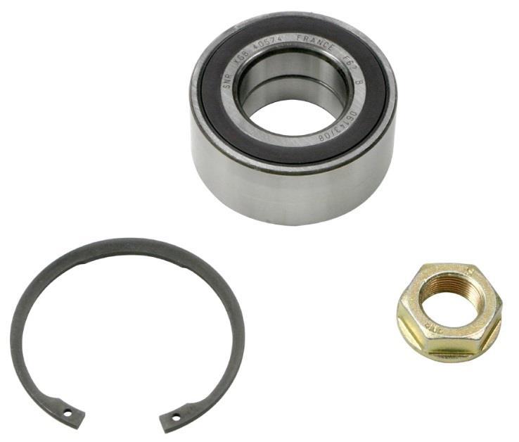

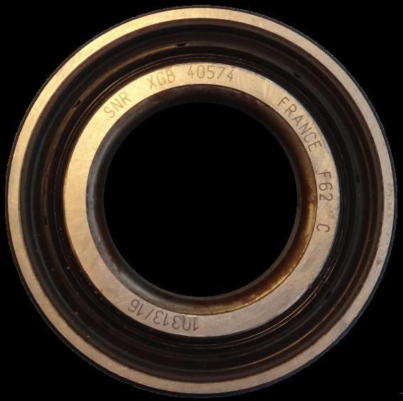

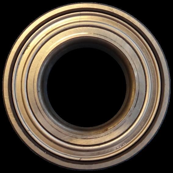


1 R Assembly/disassembly recommendations CITROËN: PEUGEOT: Berlingo, C3 (I and II), C5, C5 FL, C4, C4 B7, C3 Picasso, C4 Picasso, DS3, DS4, DS5, 307, 307 Restyling, Partner, 207, 308, 3008, 5008, RCZ, 208, 207+, 2008 OE reference , IDENTIFICATION OF NTN-SNR BEARING KIT R ASB encoder seal Traceability SNR XGB /5
.")
. The bearing cannot be removed and refitted.")
2 COMMON PROBLEMS WITH KIT R PROBLEMS WITH ROLLING NOISE AND VIBRATIONS Probable cause Incorrect installation of the bearing. A misaligned installation of the bearing in the knuckle carries a high risk of damaging the outer ring of the bearing (the side facing outward). This results in a rapid spalling of the raceway (due to the contact pressure of the balls) (no. 1). Installing the bearing backwards causes the ABS calculator to malfunction (error code, ABS warning lamp). The bearing cannot be removed and refitted. When installing the bearing, make sure that the side with the magnetic encoder is fitted facing the interior of the vehicle (i.e. facing engine / gearbox). 1 The magnetic encoder is on the same side of the bearing as the traceability code Play in the bearing. Play in the bearing can be caused by several different problems, such as a gradual loosening of the drive shaft bolt, or an incorrect initial tightening torque of the drive shaft bolt (main retaining bolt). Symptoms of play in the bearing are fretting on the face of the inner rings (no. 2) contact marks on the back of the seals caused by the rolling elements touching the rear of the seal. 2 A bearing can only be use once Damage to the encoder may occur if a magnet is brought into close proximity to the encoder seal. 2/5
 Remove the safety cotter pins (1) 3) Unscrew the castellated bolts and the drive shaft bolts (2) Re-installation tightening torque: 138 Nm 4) Disconnect the tie rod ball joint from the stub")
 Unscrew the brake bracket bolts and remove the brake calliper (3) Re-installation tightening torque: 138 Nm 9) Remove the brake discs 10) Extract drive shafts from stub axle (4)")
3 REPLACEMENT Tightening torques Drive shaft bolt: 325 Nm Wheels: with steel rim(s) 90 Nm, with aluminium rim(s) 100 Nm REMOVAL: 1) Remove the front wheels Re-installation tightening torque: 90 Nm / 100 Nm 2) Remove the safety cotter pins (1) 3) Unscrew the castellated bolts and the drive shaft bolts (2) Re-installation tightening torque: 138 Nm 4) Disconnect the tie rod ball joint from the stub axle 5) Disconnect the lower ball joint from the control arm 6) Remove the speed sensor bracket and then remove the speed sensor Re-installation tightening torque: 8 Nm 7) Disconnect the cables from the brake calliper 8) Unscrew the brake bracket bolts and remove the brake calliper (3) Re-installation tightening torque: 138 Nm 9) Remove the brake discs 10) Extract drive shafts from stub axle (4) 3/5
 and an extractor. 15) Remove the shock absorber from the stub axle.")
4 11) Move the driveshaft so it does not get in the way 12) Remove the lower fastener of the shock absorber (5) Re-installation tightening torque: 49 Nm 13) Install the extractor: OE ) Separate the stub axle slightly using a counter-bearing (OE 0606-AY) and an extractor. 15) Remove the shock absorber from the stub axle. 16) Remove the stub axle 17) Remove the wheel bearing circlip 18) Place the stub axle in a vice and apply a separator tool: OE 0903.AE (6) Compress the hub beyond the stub axle 19) Extract the bearing from the end of the stub axle 20) Tighten the counter-bearing and the separator tool 21) Apply pressure to extract the wheel bearing Using the extractor 4/5
 Re-install the rest of the components in the reverse order of removal Recommendations Carefully follow the recommendations and use the correct method of installation, all parts supplied with the")

5 RE-INSTALLATION: 1) Use a counter-bearing to press in the wheel bearing (1) 2) Install the wheel circles 3) Use the extractor to press in the hub (2). 4) Re-install the rest of the components in the reverse order of removal Recommendations Carefully follow the recommendations and use the correct method of installation, all parts supplied with the kit such as nuts, washer and circlips should always be fitted. Follow the vehicle manufacturer s installation procedures and apply the specified tightening torques. Refer to the vehicle applications in our online catalogue: eshop.ntn-snr.com Scan this QR code to access our online catalogue. FOLLOW THE RECOMMENDATIONS OF THE VEHICLE MANUFACTURER. NTN-SNR ROULEMENTS The contents of this document are the copyright of the publisher and any reproduction, even partial, is prohibited without permission. Despite the care taken in preparing this document, NTN-SNR Roulements disclaims any liability for errors or omissions that may slip through, as well as for losses or direct or indirect damage arising from its use. 5/5
R Disassembly /assembly recommendations
 CITROËN: C2, C3, C3 II, C3 Pluriel, C4 Cactus, C Elysée, DS3 PEUGEOT: 207, 207+, 208, 301, 1007, 2008 R166.03/UK/01-04/2015 R166.03 Disassembly /assembly recommendations OE reference 3350/-86 IDENTIFICATION
R Removal/installation recommendations
 R166.13 Removal/installation recommendations CITROËN: PEUGEOT: Berlingo (M49, M59), BX, Xantia (I and II), Xsara (Picasso, FL), ZX 205, 206, 305 (II), 306 (I and II), 309 (I and II), 405, Restyling, 406,
R Assembly/disassembly recommendations
 R157.32 Assembly/disassembly recommendations AUDI : SEAT : SKODA : VOLKSWAGEN : A1, A1FL, A2, S1 Cordoba IV, Ibiza(III, IV, IV FL), Toledo Fabia (FL,II, II FL, III), Roomster (FL), Rapid Polo (VII, VIII,
KD Disassembly/ Assembly recommendations
 KD457.48 Disassembly/ Assembly recommendations AUDI: SKODA: VOLKSWAGEN: KD457.48/UK/01-05/2016 A4 (Series 2, 2 FL, Cabriolet), A6 (Series 2, 2FL, Allroad), A8 Superb Passat ENGINES 2.5TDi TIMING BELT DIAGRAM
KD Assembly/disassembly recommendations
 KD457.37/UK/01-06/2014 KD457.37 Assembly/disassembly recommendations AUDI: A3 Series 1 (AU34) SEAT: Cordoba III, Ibiza II, Inca, Leon, Toledo Series 2 SKODA: Octavia II, Octavia III VOLKSWAGEN: Bora, Caddy
 Page 1 of 9 FRONT AXLE HUB & WHEEL BEARING Removal (Avalon, Camry, Camry Solara & Sienna) 1. 2. 3. 4. 5. 6. 7. 8. Remove front wheel. Check wheel bearing backlash and deviation (rotational free play).
DIAGNOSTIC EXPERT. Analysis & Recommendations. Wheel Bearing. With You
 Wheel Bearing Range DIAGNOSTIC EXPERT Analysis & Recommendations www.ntn-snr.com Main causes of failure Most failures are detected by noise; however, there are many causes 1 Indentations or breakage of
LuK Repair Solution for manual transmissions. Disassembly and assembly Special tool/failure diagnosis VW 02J
 LuK Repair Solution for manual transmissions Disassembly and assembly Special tool/failure diagnosis VW 02J The content of this brochure shall not be legally binding and is for information purposes only.
SA 8 FRONT AXLE HUB COMPONENTS
 SA8 FRONT AXLE HUB COMPONENTS SA9 REMOVAL OF FRONT AXLE HUB 1. REMOVE COTTER PIN, LOCK NUT CAP AND BEARING LOCK NUT (a) Remove the cotter pin and lock nut cap. (b) Loosen the bearing lock nut while depressing
FAG Wheel Bearing Repair Solution for Light Commercial Vehicles
 FAG Wheel Bearing Repair Solution for Light Commercial Vehicles Mercedes-Benz Sprinter, Viano, Vito and Volkswagen Crafter Front Axle The content of this brochure shall not be legally binding and is for
Front mechanical suspensions
 FRONT MECHANICAL SUSPENSIONS 9 PRINT 603.43.351/D Front mechanical suspensions Page DESCRIPTION... 11 ARTICULATED QUADRILATERAL SUSPENSION WITH TRANSVERSE LEAF SPRING... 11 SPECIFICATIONS AND DATA... 12
AXLE SYSTEM PROBLEM SYMPTOMS TABLE AH 1
 AXLE AXLE SYSTEM 1 AXLE SYSTEM PROBLEM SYMPTOMS TABLE HINT: Use the table below to help you find the cause of the problem. The numbers indicate the ranked order of probability of each of the possible causes.
Carry out replacement in the following order:
 How to replace the front hub bearing on NISSAN X-TRAIL T30 Carry out replacement in the following order: 1 Tighten the parking brake lever. 3 2 Place wedge blocks under the rear wheels. 4 Raise the front
2003 Ford Focus ZTW SUSPENSION Front - Focus
 HUB/STEERING KNUCKLE ASSEMBLY Removal 1. Loosen the strut tower nuts by at least five turns. See Fig. 4. Loosen the wheel hub retaining nut. Raise and support vehicle. Remove front wheel, brake caliper
Repair Manual VW 02J gearbox. INA GearBOX
 Repair Manual VW 02J gearbox INA GearBOX Special tools Pipe section, 50 mm: Press fitting of synchronizer body for third/fourth gear. Assembly of support bearing for input and output shaft. Part number:
2010 Jeep Truck Compass 4WD L4-2.4L
 1 of 8 3/18/2013 5:21 PM 2010 Jeep Truck Compass 4WD L4-2.4L Vehicle» Transmission and Drivetrain» Drive Axles, Bearings and Joints» Axle Shaft Assembly» Service and Repair» Half Shaft - Removal» Front
SPEED & POSITION SENSOR SOLUTIONS. With You RUGGED - ACCESSIBILITY - COMPACTNESS - PRECISION
 SPEED & POSITION SOLUTIONS RUGGED - ACCESSIBILITY - COMPACTNESS - PRECISION www.ntn-snr.com With You NTN-SNR A LEADING PLAYER NTN Corporation is a world leader as designer, developer and manufacturer of
Lower Arm ( ) Special Service Tools. Removal.
 Special Service Tools. Removal.") Page 1 of 6 (60.35.02) Special Service Tools Ball joint separator 205-754 (LRT-54-027) Halfshaft remover/replacer 204-506/1 (LRT-60-030/1) Halfshaft remover/replacer 204-506/3 (LRT-60-030/3) Retainers
Page 1 of 6 (60.35.02) Special Service Tools Ball joint separator 205-754 (LRT-54-027) Halfshaft remover/replacer 204-506/1 (LRT-60-030/1) Halfshaft remover/replacer 204-506/3 (LRT-60-030/3) Retainers
FRONT AXLE GROUP CONTENTS ON-VEHICLE SERVICE GENERAL INFORMATION GENERAL SPECIFICATIONS SERVICE SPECIFICATIONS...
 26-1 GROUP 26 CONTENTS GENERAL INFORMATION 26-2 GENERAL SPECIFICATIONS 26-3 SERVICE SPECIFICATIONS 26-4 LUBRICANTS 26-4 DIAGNOSIS 26-4 TROUBLESHOOTING STRATEGY 26-4 SYMPTOM CHART 26-4 SYMPTOM PROCEDURES
Dismounting of rolling bearings Mechanical dismounting
 Mechanical dismounting Dismounting methods Mechanical dismounting In order to prevent damage during the dismounting of bearings, various dismounting methods are used depending on the bearing size and type
1999 Toyota RAV DRIVE AXLES AWD & FWD Axle Shafts - RAV4 & RWD Axle Shafts - MR2. AWD & FWD Axle Shafts - RAV4 & RWD Axle Shafts - MR2
 1999-2000 DRIVE AXLES AWD & FWD Axle Shafts - RAV4 & RWD Axle Shafts - MR2 DESCRIPTION & OPERATION On RAV4 models, axle shafts transfer power from transaxle to front wheels (FWD), or front and rear wheels
Carry out replacement in the following order:
 Carry out replacement in the following order: 1 Tighten the parking brake lever. 3 2 Place wedge blocks under the rear wheels. 4 Raise the front of the car and secure on supports. Loosen the wheel mounting
components is critical so that the splines are not damaged. NOTE: Never force the hub unit bearing assembly onto the shaft or strike with a hammer.
 Automotive TechTips Volume 6 Issue 4 Part 3 of a 3-Part Series Installing a Hub Unit Bearing Assembly and Steering Knuckle Guidelines for Timken continues to lead the hub unit bearing evolution by providing
REAR AXLE GROUP CONTENTS GENERAL DESCRIPTION REAR AXLE DIAGNOSIS REAR AXLE HUB ASSEMBLY KNUCKLE...
 27-1 GROUP 27 CONTENTS GENERAL DESCRIPTION......... 27-2 DIAGNOSIS......... 27-2 INTRODUCTION TO DIAGNOSIS........................ 27-2 DIAGNOSTIC TROUBLESHOOTING STRATEGY...... 27-2 SYMPTOM CHART...................
See SPECIFICATIONS & PROCEDURES article in WHEEL ALIGNMENT. Lower Ball Joint 1-22 ( ) Upper Ball Joint 6-39 ( )
 Upper Ball Joint 6-39 ( )") Page 1 of 9 ARTICLE BEGINNING DESCRIPTION Front suspension uses coil springs with integral shock absorbers. Coil springs are mounted between the upper control arms and vehicle frame. A stabilizer bar controls
Page 1 of 9 ARTICLE BEGINNING DESCRIPTION Front suspension uses coil springs with integral shock absorbers. Coil springs are mounted between the upper control arms and vehicle frame. A stabilizer bar controls
1. introduction 3 2. Wheel bearing special features 4 3. Wheel bearing units from an economical point of view 5
 Motor chassis Service Technical BROCHuRE Wheel Bearing Repair Solutions for Light Commercial Vehicles CONTENT 1. introduction 3 2. Wheel bearing special features 4 3. Wheel bearing units from an economical
SUSPENSION - FRONT Toyota Celica DESCRIPTION ADJUSTMENTS & INSPECTION WHEEL ALIGNMENT SPECIFICATIONS & PROCEDURES WHEEL BEARING
 SUSPENSION - FRONT 1988 Toyota Celica FRONT SUSPENSION Toyota DESCRIPTION Vehicles are equipped with front wheel drive and independent MacPherson strut front suspension. Suspension consists of vertically
TIMING AND ACCESSORY Ranges. Diagnostic Expert Analysis & Recommendations
 Diagnostic Expert Analysis & Recommendations MAJOR CAUSES OF TIMING BELT FAILURES: 1 Uneven breakage 2 A clean break 3 Detached or separation of the belt teeth 4 Ripped teeth 5 Split teeth 6 Loss of teeth
2000 Honda Accord EX
 HUB & KNUCKLE ASSEMBLY Removal (Except Odyssey & S2000) 1. Loosen lug nuts with vehicle weight on tires. Pry lock tab away from spindle nut, and loosen nut. Raise and support vehicle. Remove lug nuts and
TABLE OF CONTENTS 0 FRONT DRIVE , WHEEL HUB , WHEEL HUB BEARING , KNUCKLE
 Subsection 01 (TABLE OF CONTENTS) TABLE OF CONTENTS 0 FRONT DRIVE... 06-02-1 1, WHEEL HUB... 06-02-2 2, WHEEL HUB BEARING... 06-02-2, KNUCKLE... 06-02- FINAL DRIVE... 06-0-1 1, DRIVE CHAIN... 06-0-2 2,
Halfshaft RH ( )
") Page 1 of 7 (47.10.02) Special Service Tools Ball joint separator 205-754 (LRT-54-027) Halfshaft remover/replacer 204-506/1 (LRT-60-030/1) Halfshaft remover/replacer 204-506/3 (LRT-60-030/3) Retainers
Page 1 of 7 (47.10.02) Special Service Tools Ball joint separator 205-754 (LRT-54-027) Halfshaft remover/replacer 204-506/1 (LRT-60-030/1) Halfshaft remover/replacer 204-506/3 (LRT-60-030/3) Retainers
3. Front Axle FRONT AXLE. A: REMOVAL 1) Lift-up the vehicle and remove the front wheels. 2) Unlock the axle nut. DS-17
 Lift-up the vehicle and remove the front wheels. 2) Unlock the axle nut. DS-17") FRONT AXLE DRIVE SHAFT SYSTEM 3. Front Axle A: REMOVAL 1) Lift-up the vehicle and remove the front wheels. 2) Unlock the axle nut. 6) Remove the disc rotor from hub. If the disc rotor seizes up within
FRONT AXLE DRIVE SHAFT SYSTEM 3. Front Axle A: REMOVAL 1) Lift-up the vehicle and remove the front wheels. 2) Unlock the axle nut. 6) Remove the disc rotor from hub. If the disc rotor seizes up within
VIBRATING SCREEN APPLICATIONS EF800 ULTAGE. Spherical roller bearings. With You
 VIBRATING SCREEN APPLICATIONS EF800 ULTAGE Spherical roller bearings With You OPTIMIZE THE EFFICIENCY OF YOUR SCREENS THE FEATURES THAT MAKE THE EF800 OPTIMISED MASSIVE BRASS CAGE: PROVEN RELIABILITY The
1990 SUSPENSION Front ES250, LS400
 SUSPENSION - FRONT Article Text 1990 Lexus LS 400 For Lextreme Copyright 1998 Mitchell Repair Information Company, LLC Thursday, January 29, 2004 04:56PM ARTICLE BEGINNING 1990 SUSPENSION Front ES250,
2 Suspension System. Suzuki Sidekick/ Geo Tracker, Suzuki Vitara. Part#:
 Part#: 037201 2 Suspension System Suzuki Sidekick/ Geo Tracker, Suzuki Vitara Rev. 062615 491 W. Garfield Ave., Coldwater, MI 49036. Phone: 517-279-2135 Web/live chat: www.bds-suspension.com. E-mail: tech@bds-suspension.com
Axle Components. Demand the original. Axle Components Driveshaft Components Repair Kits
 Axle Components Driveshaft Components Repair Kits Axle Components OE Quality Driveline Components Designed for Chrysler RAM Products www.demand.com Axle Components Driveshaft Components Repair Kits Only
All driveshafts are geared to the particular demands of the vehicle.
 Workshop Tips Trust the original GKN Driveline is the world s leading automotive driveline technology and systems engineer. With its brand SPIDAN GKN Driveline provides original GKN parts to the worldwide
REMOVAL AND INSTALLATION > HALFSHAFT
 Page 1 of 14 2008 Lincoln MKZ 3.5L Eng Service Manual: REAR DRIVE HALFSHAFTS Print Date: REMOVAL AND INSTALLATION > HALFSHAFT Special Tools Illustration Tool Name Tool Number Front Hub Remover 205-D070
FRONT AXLE HUB SUB-ASSY LH
 3038 DRIVE SHAFT / PROPELLER SHAFT REPLACEMENT HINT: COMPONENTS: SEE PAGE 304 Replace the RH side by the same procedures with LH side. 1. REMOVE FRONT WHEEL 300OI02 2. REMOVE FRONT AXLE HUB LH NUT (a)
FRONT SUSPENSION LOCATION INDEX
 1. Remove the front suspension tower bar. (See FRONT SUSPENSION TOWER BAR REMOVAL/INSTALLATION.) 2007 Mazda MX-5 Miata Sport 2007 SUSPENSION Front Suspension - MX-5 Miata FRONT SUSPENSION LOCATION INDEX
DRIVE SHAFT & FRONT AXLE
 DRIVE SHAFT & FRONT AXLE Return To Main Table of Contents GENERAL... 2 DRIVE SHAFT... 6 HUB AND KNUCKLE... 13 FRONT AXLE... 15 GENERAL GENERAL SPECIFICATIONS Drive shaft Joint type Outer Inner Length (Joint
Rear axle, servicing (frontwheel-drive
 Page 1 of 26 42-1 Rear axle, servicing (frontwheel-drive vehicles) WARNING! Do not attempt to weld and/or straighten the axle beam. Do not re-use fasteners that are worn or deformed in normal use. Some
Spring strut and spring front, replacing
 "VCC128825 EN 20090329" 1(7) Spring strut and spring front, replacing Special tools: 951 2911, 951 2914, 951 2915, 951 2564, 999 5500, 999 5576, 999 5758 Removing the spring strut Note! From model year
ZE ZE ZE. Simplex expanding wedge brake Assembly and Maintenance Instructions
 Simplex expanding wedge brake Assembly and Maintenance Instructions Simplex expanding wedge brake Assembly and Maintenance Instructions Edition 1 This publication is not subject to any update service.
1. General Description
 General Description 1. General Description A: SPECIFICATION 1. PROPELLER SHAFT Propeller shaft type 3UJ Front propeller shaft Joint-to-joint length: L 1 mm (in) 633 (24.92) Rear propeller shaft Joint-to-Joint
Carry out replacement in the following order:
 How to replace front suspension shock absorbers on Carry out replacement in the following order: 1 Replace both shock absorbers at the repair of your car at the same time. 2 Tighten the parking brake lever.
7 Drive Shaft and Axle
 7 Drive Shaft and Axle 7.1 General SPECIFICATIONS EITC0100 Drive-shaft Joint type M/T AT Outer B.J. B.J. Inner T.J. T.J. Length (Joint to joint) mm (in.) Left 380 (14.96) 349 (13.74) Right 593 (23.35)
FRONT AXLE GROUP CONTENTS FRONT AXLE HUB ASSEMBLY GENERAL INFORMATION GENERAL SPECIFICATIONS
 26-1 GROUP 26 COTETS GEERAL IFORMATIO 26-2 GEERAL SPECIFICATIOS 26-4 SERVICE SPECIFICATIOS 26-5 LUBRICATS 26-5 DIAGOSIS 26-5 TROUBLESHOOTIG STRATEGY 26-5 SYMPTOM CHART 26-5 SYMPTOM PROCEDURES 26-6 SPECIAL
E31 Repair Procedure Replace Front Wheel Hub/Bearing Assembly
 E31 Repair Procedure 31-21 Replace Front Wheel Hub/Bearing Assembly Disclaimer This repair procedure is provided as is and is not authoritative with respect to any BMW repair operation. Mark F. Fling is
1 of 5 1/10/2017 5:10 PM
 1 of 5 1/10/2017 5:10 PM Shock Module Yoke Replacement ^ Tools Required - J 24319-B Steering Linkage and Tie Rod Puller Removal Procedure 1. Raise and support the vehicle. Refer to Vehicle Lifting. 2.
Parking brake Mechanical brake acting on rear wheels
 11 Brake System 11.1 General SPECIFICATIONS EJTC0010 Master cylinder Type Tandem type I.D. mm(in.) 20.64 mm (0.813 in.) Fluid level warning sensor Provided Brake booster Type Vacuum Boosting ratio 4.0
Axle Components. Demand the original. Axle Components Driveshaft Components Repair Kits
 Axle Components Driveshaft Components Repair Kits Axle Components OE Quality Driveline Components Designed for Chrysler RAM Products www.demand.com Axle Components Driveshaft Components Repair Kits Only
1. General Description
 General Description 1. General Description A: SPECIFICATION 1. PROPELLER SHAFT Model All models Propeller shaft type EDJ Front propeller shaft Joint-to-joint length: L 1 mm (in) AT 735.5 (28.96) MT 675.5
Axle Components. Demand the original. Axle Components Driveshaft Components Repair Kits
 Axle Components Driveshaft Components Repair Kits Axle Components OE Quality Driveline Components Designed for Chrysler RAM Products www.demand.com Axle Components Driveshaft Components Repair Kits Only
GROUP 33A 33A-1 CONTENTS GENERAL DESCRIPTION... 33A-2 FRONT SUSPENSION DIAGNOSIS. 33A-3 LOWER ARM... 33A-13 SPECIAL TOOLS... 33A-5
 33A-1 GROUP 33A CONTENTS GENERAL DESCRIPTION 33A-2 DIAGNOSIS 33A-3 INTRODUCTION TO FRONT SUSPENSION DIAGNOSIS 33A-3 DIAGNOSIS TROUBLESHOOTING STRATEGY 33A-3 SYMPTOM CHART 33A-3 SYMPTOM PROCEDURES 33A-3
FRONT SUSPENSION GROUP 33A 33A-1 CONTENTS GENERAL DESCRIPTION... 33A-2 FRONT SUSPENSION DIAGNOSIS. 33A-3 LOWER ARM... 33A-13 SPECIAL TOOLS...
 33A-1 GROUP 33A FRONT SUSPENSION CONTENTS GENERAL DESCRIPTION......... 33A-2 DIAGNOSIS. 33A-3 INTRODUCTION TO DIAGNOSIS........................ 33A-3 DIAGNOSIS TROUBLESHOOTING STRATEGY...... 33A-3 SYMPTOM
Wheel Hub: Service and Repair Front
 2004 Acura Truck MDX V6-3471cc 3.5L Copyright 2009, ALLDATA 10.10 Page 1 Wheel Hub: Service and Repair Front Knuckle/Hub Replacement Special Tools Required - Ball joint remover, 28 mm 07MAC-SL00200 - Hub
SECTION ZF FRONT AXLE
 04-101.01/ 1 2011JA14 SECTION 04-101.01 6 3 5 1 2 9 1. Upper radius rod 2. Lower radius rod 3. Caliper 4. BRAKE Disk 5. Pneumatic connector 6. Hub 7. steering knuckle 8. Grease Fitting 9. Pneumatic connector
Audi B6/B7 A4/S4 Rear Wheel Bearing Service Kit
 Audi B6/B7 A4/S4 Installation Tutorial ES2561175 This tutorial is provided as a courtesy by ECS Tuning. Proper service and repair procedures are vital to the safe, reliable operation of all motor vehicles
REAR AXLE <FWD> GROUP 27A 27A-1 CONTENTS GENERAL INFORMATION... 27A-2 SPECIAL TOOLS... 27A-4 ON-VEHICLE SERVICE... 27A-5 SPECIFICATIONS...
 27A-1 GROUP 27A CONTENTS GENERAL INFORMATION........ 27A-2 SPECIFICATIONS............... 27A-2 SERVICE SPECIFICATIONS........... 27A-2 REAR AXLE DIAGNOSIS......... 27A-3 INTRODUCTION TO REAR AXLE DIAGNOSIS........................
Front Driveshaft - Right - Remove and Install ( )
") «Galaxy Table of Contents» «Group 14: Front Axle, Suspension and Driveshafts» «Section 14-02: Front Axle and Driveshafts» «REMOVAL AND INSTALLATION» Front Driveshaft - Right - Remove and Install (14 321
«Galaxy Table of Contents» «Group 14: Front Axle, Suspension and Driveshafts» «Section 14-02: Front Axle and Driveshafts» «REMOVAL AND INSTALLATION» Front Driveshaft - Right - Remove and Install (14 321
ALLDATA Online Dodge Truck Caravan V L - Front. Front
 Page 1 of 10 Home Account Contact ALLDATA Log Out Help PAUL REDEHOFT Select Vehicle New TSBs Technician's Reference Component Search: OK 1994 Dodge Truck Caravan V6-201 3.3L Conversion Calculator Vehicle
1940 Hudson SERVICING THE FRONT SUSPENSION SYSTEM
 1940 Hudson SERVICING THE FRONT SUSPENSION SYSTEM Source of this material is from 1940 Series, Issue 3, November-December Hudson Service Magazine SERVICING THE FRONT SUSPENSION SYSTEM No set rule can be
SERVICE MANUAL US. Permobil M300/M400. Power Wheelchair
 SERVICE MANUAL US Permobil M300/M400 Power Wheelchair How to contact Permobil Head Office of the Permobil group Produced and published by Permobil AB, Sweden Version 2, 2011-06 Article no.: 205261-US-0
WHEEL ALIGNMENT SPECIFICATIONS & PROCEDURES
 WHEEL ALIGNMENT SPECIFICATIONS & PROCEDURES 1988 Jeep Cherokee 1988 Wheel Alignment INTRODUCTION PRE-ALIGNMENT VEHICLE CHECKS Prior to making wheel alignment adjustments, check and adjust the following
POLIPUMP YOUR OWN CENTRALISED LUBRICATION SYSTEM IN JUST A FEW QUICK STEPS. Easy set up, economical and powerful
 POLIPUMP YOUR OWN CENTRALISED LUBRICATION SYSTEM IN JUST A FEW QUICK STEPS Easy set up, economical and powerful Set up your own multipoint lubrication in only 4 steps From 1 to 35 points to lubricate up
REMOVAL AND INSTALLATION
 204-00-1 Suspension System 204-00-1 REMOVAL AND INSTALLATION Wheel Bearing, Hub, Knuckle, Upper Arm and Lower Arm Rear Special Tool(s) 3. Remove the parts in the order indicated in the following illustrations
FRONT AXLE GROUP CONTENTS GENERAL DESCRIPTION FRONT AXLE DIAGNOSIS DRIVE SHAFT ASSEMBLY SPECIAL TOOLS...
 26-1 GROUP 26 CONTENTS GENERAL DESCRIPTION 26-2 DIAGNOSIS 26-2 TROUBLESHOOTING STRATEGY 26-2 SYMPTOM CHART 26-3 SYMPTOM PROCEDURES 26-3 SPECIAL TOOLS 26-4 ON-VEHICLE SERVICE 26-6 WHEEL BEARING END PLAY
SUSPENSION 2-1 SUSPENSION TABLE OF CONTENTS
 DN SUSPENSION 2-1 SUSPENSION TABLE OF CONTENTS page ALIGNMENT... 1 FRONT SUSPENSION - 4x2... 6 page FRONT SUSPENSION - 4x4... 14 REAR SUSPENSION... 23 ALIGNMENT TABLE OF CONTENTS page AND OPERATION WHEEL
DIFFERENTIALS & AXLE SHAFTS
 DIFFERENTIALS & AXLE SHAFTS 2001 Chevrolet Camaro 2000-01 DRIVE AXLES General Motors Differentials & Axle Shafts Chevrolet; Camaro Pontiac; Firebird DESCRIPTION & OPERATION Drive axle is a semi-floating,
Wheel Bearing and Wheel Hub All-Wheel Drive (AWD) Vehicles
 Vehicles") Rear Suspension Wheel Bearing and Wheel Hub All-Wheel Drive (AWD) Vehicles All-Wheel Drive (AWD) Vehicles Front Wheel Drive (FWD) Vehicles Removal All vehicles NOTICE: Suspension fasteners are critical
Rear Suspension Wheel Bearing and Wheel Hub All-Wheel Drive (AWD) Vehicles All-Wheel Drive (AWD) Vehicles Front Wheel Drive (FWD) Vehicles Removal All vehicles NOTICE: Suspension fasteners are critical
HYDRAULIC NUT HMV..EBF
 HYDRAULIC NUT HMV..EBF INSTRUCTIONS FOR USE www.ntn-snr.com With You Warning PRESSURE MAX HMV EBF 10-25 700 bar HMV EBF 26-40 550 bar HMV EBF 41-60 450 bar HMV EBF 62-100 400 bar HMV EBF 102-120 350 bar
Workshop Tips Steering Parts
 Workshop Tips Steering Parts Competence from the technology leader GKN Aftermarkets & Services is your preferred partner for driveline parts and systems, repair and maintenance, complete design and build
SCdefault. 900 Installation instructions
 SCdefault 900 Installation instructions SITdefault Sports chassis MONTERINGSANVISNING INSTALLATION INSTRUCTIONS MONTAGEANLEITUNG INSTRUCTIONS DE MONTAGE Accessories Part No. Group Date Instruction Part
SECTION 2D REAR SUSPENSION TABLE OF CONTENTS
 SECTION 2D REAR SUSPENSION TABLE OF CONTENTS Description and Operation.................. 2D-2 Rear Suspension.......................... 2D-2 Component Locator........................ 2D-3 Rear Suspension..........................
ORIGA SYSTEM PLUS Guides, Brakes and Valves for Modular Linear Drive Systems OSP Appendix to the Operating Instructions
 ORIGA SYSTEM PLUS Guides, Brakes and Valves for Modular Linear Drive Systems OSP Appendix to the Operating Instructions TAll personnel who have anything to do with the OSP fitted with guides, brakes or
SUSPENSION SYSTEM PROBLEM SYMPTOMS TABLE SP 1
 SUENSION SUENSION SYSTEM 1 Vehicle/pulls Bottoming Sway/pitches Wheel shimmy Abnormal tire wear SUENSION SYSTEM PROBLEM SYMPTOMS TABLE Use the table below to help determine the cause of the problem. The
REMOVAL & INSTALLATION
 Page 1 of 6 REMOVAL & INSTALLATION AXLE SHAFTS Removal Raise and support vehicle. Remove front wheels. Remove engine undercovers. Remove cotter pin and lock nut cap. See Fig. 2. Apply brakes and remove
ARTICLE BEGINNING DESCRIPTION ADJUSTMENTS & INSPECTION SUSPENSION Rear. Golf III
 Article Text ARTICLE BEGINNING 1995-96 SUSPENSION Rear Golf III DESCRIPTION Suspension uses control arms and axle beam for stabilization. Control arms and axle beam are combined as one unit. Brake drums
Competence from the Original Equipment Supplier
 Workshop Tips Competence from the Original Equipment Supplier GKN Driveline is the world s leading supplier of automotive driveline components and systems. Our global market leadership is based on a strong
Halfshaft SPECIAL SERVICE TOOL(S) REQUIRED
 REQUIRED") Page 1 of 8 Section 05-04: Halfshaft, Front Wheel 1999 Taurus/Sable Workshop Manual REMOVAL AND INSTALLATION Procedure revision date: 06/25/1998 Halfshaft SPECIAL SERVICE TOOL(S) REQUIRED Description Tool
Page 1 of 8 Section 05-04: Halfshaft, Front Wheel 1999 Taurus/Sable Workshop Manual REMOVAL AND INSTALLATION Procedure revision date: 06/25/1998 Halfshaft SPECIAL SERVICE TOOL(S) REQUIRED Description Tool
TO INDEX DIFFERENTIAL FRONT DIFFERENTIAL CARRIER OIL SEAL (4WD) FRONT DIFFERENTIAL CARRIER ASSEMBLY (4WD) REAR DIFFERENTIAL CARRIER OIL SEAL
 FRONT DIFFERENTIAL CARRIER ASSEMBLY (4WD) REAR DIFFERENTIAL CARRIER OIL SEAL") TO INDEX DRIVE LINE / AXLE DIFFERENTIAL DIFFERENTIAL SYSTEM PRECAUTIONS.............................................. OPERATION CHECK......................................... PROBLEM SYMPTOMS TABLE.................................
TO INDEX DRIVE LINE / AXLE DIFFERENTIAL DIFFERENTIAL SYSTEM PRECAUTIONS.............................................. OPERATION CHECK......................................... PROBLEM SYMPTOMS TABLE.................................
Fitting-removal and maintenance
 Fitting-removal and maintenance Fitting of bearings 136 General rules 136 Fitting principles 136 Hot fitting 137 Press fitting (or with anti-rebound hammer) 138 Adapter sleeves 139 Removal of bearings
1984 Dodge W250 PICKUP
 1984 Dodge W250 PICKUP Submodel: Engine Type: V8 Liters: 5.2 Fuel Delivery: CARB Fuel: GAS Dana 44 MODELS THROUGH 1984 2. Raise and safely support the vehicle, then remove the wheel hub and bearings as
SERVICE MANUAL. Permobil C350. Power Wheelchair
 SERVICE MANUAL US Permobil C350 Power Wheelchair Contents Contents Introduction... 5 Rating plates... 6 Covers... 8 Batteries... 10 Rear wheels... 12 Support wheels... 14 Front wheels... 16 Wheel fork...
Dacia Duster Explorers UK
 3 Chassis 30A GENERAL INFORMATION 31A FRONT AXLE COMPONENTS 33A REAR AXLE COMPONENTS 35A WHEELS AND TYRES 36A STEERING ASSEMBLY 36B POWER ASSISTED STEERING 37A MECHANICAL COMPONENT CONTROLS 38C ANTI-LOCK
1993 SUSPENSION Volkswagen Rear. EuroVan
 Article Text ARTICLE BEGINNING 1993 SUSPENSION Volkswagen Rear EuroVan DESCRIPTION Suspension uses control arms and axle beam for stabilization. Control arms and axle beam are combined as one unit. Brake
REAR TRANSMISSION-REAR AXLE
 REAR TRANSMISSION-REAR AXLE The rear axle is of the semi-floating type with a spiral bevel drive pinion and crown wheel as shown in the section view, Fig. 168. 7 The drive is splined into the front transmission
Rear Sway Bar for XC90 ( ) 2.5T and T6 ipd mounting kit SBK42
 2.5T and T6 ipd mounting kit SBK42") Dedicated to improving vehicle fun, safety & performance Installation Instructions Rear Sway Bar for XC90 (2003-0) 2.5T and T6 ipd mounting kit SBK2 PI-298 08/06 Thank you for purchasing this anti-sway
Dedicated to improving vehicle fun, safety & performance Installation Instructions Rear Sway Bar for XC90 (2003-0) 2.5T and T6 ipd mounting kit SBK2 PI-298 08/06 Thank you for purchasing this anti-sway
LL SerieS SeLf Steer AxLe Kingpin BeAringS removal & replacement
 LL Series Self steer Axle Kingpin Be a r i n g s Removal & Replacement December 2010 Remove the axle. Take off the hubs and brake parts, see the handbooks for the corresponding rigid axles. Take off the
1. SPECIFICATIONS 2. WHEEL ALIGNMENT Front Suspension. (gas type) Rear Suspension. (gas type)
 Rear Suspension. (gas type)") 441101 053 1. SPECIFICATIONS Front Suspension Rear Suspension Description Suspension type Spring type Shock absorber type Stabilizer bar type Suspension type Spring type Shock absorber type Stabilizer
441101 053 1. SPECIFICATIONS Front Suspension Rear Suspension Description Suspension type Spring type Shock absorber type Stabilizer bar type Suspension type Spring type Shock absorber type Stabilizer
REAR HUB UNIT BEARING
 2014 Subaru Forester F4-2.5L DOHC Vehicle > Steering and Suspension > Wheels and Tires > Wheel Bearing > Service and Repair > Removal and Replacement REAR HUB UNIT BEARING Rear Hub Unit Bearing REMOVAL
4. REMOVAL AND INSTALLATION
 12 4610 4. REMOVAL AND INSTALLATION Steering Column Shaft Preceding Work: Disconnect the negative battery cable and place the tires to straight ahead direction. Removal and Installation 1. Unscrew the
REAR SUSPENSION GROUP CONTENTS GENERAL DESCRIPTION REAR SUSPENSION DIAGNOSIS LOWER ARM AND TOE CONTROL ARM ASSEMBLY...
 34-1 GROUP 34 CONTENTS GENERAL DESCRIPTION........... 34-2 DIAGNOSIS.... 34-2 INTRODUCTION....................... 34-2 TROUBLESHOOTING STRATEGY........ 34-2 SYMPTOM CHART..................... 34-3 SYMPTOM
SUSPENSION 2-1 SUSPENSION CONTENTS
 DN SUSPENSION 2-1 SUSPENSION CONTENTS page ALIGNMENT... 1 FRONT SUSPENSION... 5 page REAR SUSPENSION... 13 ALIGNMENT INDEX page GENERAL INFORMATION WHEEL ALIGNMENT... 1 DIAGNOSIS AND TESTING PRE-ALIGNMENT
If it exceeds the maximum specification, replace the propeller shaft.
 If it exceeds the maximum specification, replace the propeller shaft. Maximum runout o 0.4 mm {0.016 in} 2. Inspect the play and rotation of the joint by turning the universal joint in the directions shown
Technical Note6019A X61, and TL4 - X77, and TL4 - X84, and TL4 - X85, and TL4 - X91, and TL4 - X95, and TL4 TL4 manual gearbox
 Technical Note6019A X61, and TL4 - X77, and TL4 - X84, and TL4 - X85, and TL4 - X91, and TL4 - X95, and TL4 TL4 manual gearbox Edition 9 77 11 335 822 APRIL 2009 Edition Anglaise "The repair methods given
SUSPENSION - REAR Toyota Celica DESCRIPTION ADJUSTMENTS & INSPECTION WHEEL ALIGNMENT SPECIFICATIONS & PROCEDURES WHEEL BEARING
 SUSPENSION - REAR 1988 Toyota Celica REAR SUSPENSION Toyota IRS DESCRIPTION The Toyota Independent Rear Suspension (IRS) system utilizes MacPherson struts, which fasten to axle carrier and wheel housing.
1. Set the position of the hub to FREE and remove the six hex-drive bolts.
 1. Raise vehicle on a hoist, remove road wheels, disconnect the drag-link from the passenger-side hub assembly and disconnect the steering tie rod ends from both the driver and passenger side hub assemblies.
BRAKE SYSTEM Return To Main Table of Contents
 BRAKE SYSTEM Return To Main Table of Contents GENERAL... 2 BRAKE PEDAL... 10 MASTER CYLINDER... 13 BRAKE BOOSTER... 16 BRAKE LINE... 18 PROPORTIONING VALVE... 19 FRONT DISC BRAKE... 20 REAR DRUM BRAKE...