Valve manifold CPV10-EX-VI, Compact Performance
|
|
|
- Sheryl Phillips
- 6 years ago
- Views:
Transcription
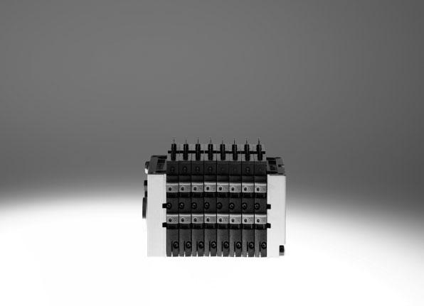
1
2 Key features Innovative Versatile Reliable Easy to mount Cubic design for exceptional performance and low weight Sturdy Optimised for installation in a control cabinet Suitable for pilot control of process valves High flow rate with extremely compact design Up to sixteen 2/2 or 3/2-way valves per valve manifold thanks to twovalve function in each slice Flexible and cost-effective connection of 2 to 8 valve slices Highly flexible thanks to: various pneumatic functions (valve variants) different pressure ranges Separator plates for creating pressure zones Blanking plates for future expansion Manual overrides for valves Protection class to IP65 in the control cabinet Intrinsically safe valve manifold design to ATEX Category 2 (Zone ) Extremely robust thanks to the metal valve design Long service life Ready-to-install and tested unit Lower selection, ordering, installation and commissioning costs Secure mounting on wall or H-rail Pneumatic multiple connector plate fast replacement of the valve block without the need to replace the existing tubing connections Valve assembly optimised for control cabinets 2 Internet: Subject to change 208/02
3 Key features Main features Simple electrical connections: Individual connection Inscription labels Quick mounting: Directly using screws On an H-rail Via the pneumatic multiple connector plate Robust metal thread or pre-assembled QS connectors Reliable operation: Manual override, non-detenting, detenting or blocked Comprehensive range of valve functions, pressure zone creation, blanking plates Width 0 mm Equipment options Valve functions 5/2-way valve, single solenoid 5/2-way valve, double solenoid 2x 3/2-way valve, normally open 2x 3/2-way valve, normally closed 2x 3/2-way valve, x normally open, x closed 2x 3/2-way valve, normally closed, with integrated back pressure protection 5/3-way valve ) 2x 2/2-way valve, normally closed 2x 2/2-way valve, x normally open, x closed Special features Individual connection 2 8 valve positions, max. 6 solenoid coils Intrinsically safe The valve manifold CPV0-EX-VI features an intrinsically safe design for use in potentially explosive areas to ATEX Category 2 (Zone ) Pneumatic multiple connector plate Pneumatic multiple connector plate for wall opening facilitates installation in control cabinets, seal to IP65 Operation Actuation only via intrinsically safe circuit with individual valve connection ) Via function block, not in conjunction with pneumatic multiple connector plate 208/02 Subject to change Internet: 3
4 Key features Electrical connections Individual connection in explosion-proof design The CPV0-EX-VI is a valve manifold featuring an intrinsically safe design for use in Zone potentially explosive areas (ATEX Category 2 G). Definition of intrinsically safe: Intrinsically safe means that the electrical outputs and solenoid coils are designed so that no sparks or thermal effects will trigger ignition in explosive atmospheres. Each valve coil must be connected to an intrinsically safe circuit that complies with ignition protection type ia IIC or ib IIC. Individual connection permits the selection of 2 to 6 solenoid coils (divided between two to eight valve slices, odd numbers also possible). Range of applications Many applications involve explosive gases or dust. Applications such as these call for equipment with increased explosion protection requirements (Category 2 corresponding to Zone ). The possibility of sparking, for example when a solenoid coil is switched off, must be completely ruled out. There are different ways of doing this. Solenoid coils for this type of application are usually intrinsically safe. Intrinsically safe here means that no sparks or thermal effects can occur that would trigger ignition in an explosive atmosphere. The valve terminal family CPV0 is already approved for explosion protection areas to ATEX. This approval is valid for Category 3. It corresponds to Zone 2 in which an explosive atmosphere either normally does not occur or occurs only briefly. The valve manifold CPV0-EX-VI extends this range for higher ATEX requirements: Approval for Category 2, Zone. The intrinsically safe valve manifold features an integrated protective circuit that prevents ignition for gas, mist or vapour. Circuits for intrinsically safe solenoid coils are also designed so that only low voltage and power levels can occur. Hence, in this case the valve manifold is equipped with individually connected valves. The CPV0-EX-VI can only be operated in suitable intrinsically safe circuits. In process engineering, valves for pilot control of process valves are frequently installed in a control cabinet. The pneumatic multiple connector plate type CPV0-VI- -M7-C or -D for control cabinets simplifies the installation of the pneumatic connections. Instead of multiple bulkhead fittings and tubing connections, installation can be carried out with just a single through-hole in the cabinet wall. Protection class IP65 is achieved via a sealing ring suitable for closed control cabinet assembly. The pneumatic multiple connector plate facilitates operation of the valve manifold CPV0-EX-VI in a suitable control cabinet in Zones and 2 (ATEX Category 2 GD). 4 Internet: Subject to change 208/02

5 Selection and development Valve manifold configurator The appropriate valve manifold can be chosen quickly and easily using the online catalogue. This includes an easy-to-use valve manifold configurator, which makes it much easier to find the right product. The valve manifolds are fully assembled according to your order specification and are individually tested. This reduces assembly and installation time to a minimum. You order a valve manifold CPV0-EX-VI using the order code. Ordering system for CPV0-EX-VI Internet: cpv0-ex Online via: 2D/3D CAD data You can request the CAD data for a valve manifold you have configured. To do so, perform the product search as described above. Go to the shopping basket and click on the CAD icon (compass). On the next page you can generate a 3D preview or request another data format of your choice by . Online via: 208/02 Subject to change Internet: 5
 Use in hazardous locations II 2G Ex ib IIC T4 Gb II 2D Ex ib IIC T00")


6 Key features Certification In accordance with EU Directive 94/9/EC (ATEX Directive) Use in hazardous locations II 2G Ex ib IIC T4 Gb II 2D Ex ib IIC T00 C Db 5 C Ta 50 C CPV use in Zone /2 CPV use in Zone /2 Intrinsically safe valve manifold in a control cabinet. Actuation via multicore connecting cable. Intrinsically safe valve manifold (pneumatic multiple connector plate) and remote I/O in a control cabinet. 6 Internet: Subject to change 208/02
7 Key features What does ATEX mean? Explosive atmospheres are a constant hazard in the chemical and petrochemical industries because of the processing techniques used. These explosive atmospheres are caused by escaping gas, vapours and mist, for example. Explosive atmospheres can also be expected in mills, silos and sugar and feed processing plants because of the dust/oxygen mixtures that occur there. For this reason, electrical equipment in hazardous areas is subject to a special directive, ATEX 95a. This directive was also extended to non-electrical equipment on July What does ATEX 95a stand for and what does it mean? ATEX is an acronym of the French expression Atmosphère explosible. ATEX 95a refers to article 95a of the corresponding EU directive. ATEX 95a is a working title for a project related to the Directive 94/9/EC: Directive 94/9/EC stipulates the minimum safety requirements for equipment and protective systems to be operated in explosive atmospheres. It applies to all EU member states. It relates to both electrical and non-electrical equipment. What are the main amendments introduced by Directive 94/9/EC? Non-electrical equipment such as cylinders, pneumatic valves, service units and accessories now fall within the scope of the directive. Equipment will be approved for specific categories. These categories are allocated zones in which the equipment can be operated. Each piece of equipment must be supplied with operating instructions and a conformity declaration. The manufacturer s quality system must meet specifications over and above those required under ISO 900. The new equipment bears the explosion protection and CE marks. Dust explosion protection now also falls within the scope of this directive. It specifies general safety requirements. It applies to mining as well as all other hazardous areas. It applies to complete protective systems. Explosion protection classes Gas Dust Frequency Equipment group Equipment category Area of application zone zone I M Mining M M2 II All non-mining areas of application 0 Constant, frequent, long-term II G Gas, mist, vapour 20 II D Dust Occasional II 2G Gas, mist, vapour 2 II 2D Dust 2 Seldom, short-term in the event II 3G Gas, mist, vapour 22 of a fault II 3D Dust 208/02 Subject to change Internet: 7
8 Key features CPV The benefits at a glance The CPV has a unique design. It permits the flexible combination of pneumatic performance, electrical connection technologies and a wide range of mounting options. The pneumatic multiple connector plate supports space-saving installation in control cabinets. In many cases the valve manifold can be installed in the previously unused wall area of the control cabinet. There is no need to connect the valves in the control cabinet. All tube couplings can be laid externally. Instead of individual holes, the pneumatic multiple connector plate requires only one rectangular cutout. The generously sized flow ducts and powerful flat plate silencers ensure high flow rates. All valves are in the form of valve slices. They are optimised for flow performance and are also extremely compact. Two functions per valve slice (e.g. 2x 3/2-way valves) mean that twice the component density can be achieved. This saves space and reduces costs. The cubic design permits exceptional performance yet a comparatively low weight. The benefits of this design are obvious when the valve manifold is used on a drive in a moving installation. However, robustness must not be sacrificed in favour of compactness. The connecting threads and mounting attachments are metal. The manual override for the valves can be adapted for different operating situations. If, for example, a detenting manual override is required for setting-up mode, the manual override can be easily converted for that application in a way that rules out operational errors. The design principle The cubic design provides a clearly assigned function on each side. Thus, for example, the electrical connection is mounted on the top. The different combination options ensure the optimum solution for the task at hand. Compressed air supply connections on the left, right or underneath Pneumatic working lines and function blocks (vertical stacking) underneath Manual operation from the front Electrical connection surface on the top Mounting surface at the back or the front via a pneumatic multiple connector plate 8 Internet: Subject to change 208/02
9 Peripherals overview Overview CPV valve manifold aa aj Basic electrical unit (individual connection) 2 Right-hand end plate with flat plate silencer 3 Valve slice 4 Right-hand end plate (threaded connections not in conjunction with pneumatic multiple connector plate) 5 Pneumatic multiple connector plate 6 Push-in connectors 7 Left-hand end plate (threaded connections not in conjunction with pneumatic multiple connector plate) 8 Left-hand end plate with flat plate silencer 9 H-rail mounting aj Wall mounting aa Plug socket with cable 208/02 Subject to change Internet: 9
10 Key features Pneumatic components Valves CPV valves are valves with integrated sub-base, i.e. in addition to the valve function they contain all of the pneumatic ducts for supply, exhaust and the working lines. The supply ducts are a central component of the valve slices and allow a direct flow of air through the valve slices. This helps achieve maximum flow rates. All valves have a pneumatic pilot control for optimising performance. The valve function is based on a piston spool system with a patented sealing principle that guarantees its suitability for a wide range of applications as well as a long service life. The valve manifold is not suitable for vacuum operation. Valve function Code Circuit symbol Description M 5/2-way valve, single solenoid Pneumatic spring return Piston spool valve J 5/2-way valve, double solenoid Piston spool valve The pneumatic switching position is retained in the de-energised state C 2x 3/2-way valve, single solenoid Normally closed Pneumatic spring return Piston spool valve CY N H 2x 3/2-way valve, single solenoid Normally closed Pneumatic spring return Piston spool valve Integrated back pressure protection -H- Note The valve manifold must be operated with external pilot air supply if it is necessary to ensure that the back pressure flaps are closed securely in the event of a sudden drop in operating pressure or if the operating pressure is switched off. 2x 3/2-way valve, single solenoid Normally open Pneumatic spring return Piston spool valve The function of a 5/3-way valve with mid-position pressurised can be implemented with these valves with initial position open. 2x 3/2-way valve, single solenoid Normal position x open (pilot control 2) x closed (pilot control 4) Pneumatic spring return Piston spool valve For optimised cylinder movement. Corresponds to valve function M with simultaneous actuation of both solenoid coils (5/2-way, single solenoid). Since the piston area on each side can be pressurised or exhausted separately, it means that the cylinder can move faster. 0 Internet: Subject to change 208/02
11 Key features Pneumatic components Valve function Code Circuit symbol Description 5/3G ) function, mid-position closed The valve function mid-position closed is created from one 2x 3/2-way valve, normally closed (code C). The valve kit CPV0-BS-5/3G-M7 (incorporating a double piloted non-return function) is used for this. This valve kit is intended for applications with one working pressure level per valve slice, i.e. it must not be used in dual-pressure applications (where the pressure levels at port and are different). If other valve slices are to be used in dual-pressure mode, then the valve slice equipped with the 5/3G valve kit must be separated from compressed air duct and by means of a separator plate (code T). Not in first or last valve position with pneumatic multiple connector plate P and M. Cannot be used with pneumatic multiple connector plate GQC and GQD. Piston spool valve 5/3E function, mid-position exhausted The valve function mid-position exhausted is created using a 2x 3/2-way valve, normally closed (code C). Pneumatic spring return Piston spool valve 5/3B function, mid-position pressurised The valve function mid-position pressurised is created using a 2x 3/2-way valve, normally open (code N). Pneumatic spring return Piston spool valve D 2x 2/2-way valve, single solenoid Normally closed Pneumatic spring return Piston spool valve I 2x 2/2-way valve, single solenoid Normal position x open (control side 2) x closed (control side 4) Pneumatic spring return Piston spool valve ) Cannot be assembled in conjunction with the control cabinet version of the pneumatic multiple connector plate CPV0-VI-P...-C or CPV0-VI-P...-D 208/02 Subject to change Internet:
12 Key features Pneumatic components Additional pneumatic functions Code Circuit symbol Description P Input (valve side) Output (cylinder side) 2x one-way flow control valve, supply air flow control Module (actuator) for direct flange mounting on the CPV valves. Also suitable for pneumatic multiple connector plates. Different valve actuators cannot be combined. Not with valve function G Not in first or last valve position with accessories M, P, V (pneumatic multiple connector plate) Cannot be used with accessories GQC and GQD (pneumatic multiple connector plate) Q Input (valve side) Output (cylinder side) 2x one-way flow control valve, exhaust air flow control Module (actuator) for direct flange mounting on the CPV valves. Also suitable for pneumatic multiple connector plates. Different valve actuators cannot be combined. Not with valve function G Not in first or last valve position with accessories M, P, V (pneumatic multiple connector plate) Cannot be used with accessories GQC and GQD (pneumatic multiple connector plate) -H- Note Pneumatic multiple connector plate P, M: not in first or last valve position. Pneumatic multiple connector plate GQC, GQD: not used. 2 Internet: Subject to change 208/02
13 Key features Pneumatic components Creating pressure zones Different pressures at port and result in two pressure levels per valve. This means, for example, that a cylinder drive can be advanced using high pressure and retracted using low pressure to save energy. The maximum number of pressure zones possible is determined by the combination of the following components: Use of a separator plate End plate pair type Valve slice type The CPV valve manifold can be divided into 2 to 4 pressure zones with the aid of separator plates. Separator plates Code Graphical symbol Note T Separator plate (for creating pressure zones), supply duct separated Pilot exhaust air Pilot air supply Exhaust air Working air Working air 2/4 3/5 A separator plate (code T) is used to separate the duct for the air supply (port and ) to provide two pressure zones. Not in first or last valve position Not with compressed air supply A, B, C, D, U, V, W, X S L Separator plate (for creating pressure zones), supply duct and exhaust 3/5 separated Pilot exhaust air Pilot air supply Exhaust air Working air Working air Vacant position (blanking plate) 2/4 3/5 Pilot exhaust air Pilot air supply Exhaust air 2/4 3/5 Working air Working air The separator plate (code S) separates the exhaust duct 3/5 as well as the supply duct and. This plate should be used to prevent back pressure on neighbouring valve functions. Not in first or last valve position Not with compressed air supply A, B, C, D, U, V, W, X (single-side compressed air supply) A blanking plate (code L) is used to create a vacant position where a valve can be positioned at a later date. 208/02 Subject to change Internet: 3
14 Key features Pneumatic components Examples: Compressed air supply External pilot air supply, flat plate silencer at both ends Compressed air supply via pneumatic multiple connector plate: code H The diagram opposite shows an example of the configuration and connection of the compressed air supply with external pilot air supply. Port 2/4 on the pneumatic multiple connector plate is equipped with a fitting for this purpose. Ports 3/5 and are vented via the flat plate silencers. One separating seal each can be optionally used to create pressure zones. Optional separating seal Internal pilot air supply, ducted exhaust air or threaded silencer Compressed air supply via end plates: code Z The diagram opposite shows an example of the configuration and connection of the compressed air supply with internal pilot air supply. The pilot air supply is branched from port or via the right-hand end plate. Ports 3/5 and are vented via the threaded silencer. One separating seal each can be optionally used to create pressure zones. Optional separating seal 4 Internet: Subject to change 208/02
15 Key features Pneumatic components Example: Creating pressure zones CPV with separator plate T With the CPV valve manifold up to four pressure zones can be implemented. The diagram shows an example of the configuration and connection of four pressure zones using separator plate code T with external pilot air supply. Zone 2 Zone Zone 4 Zone Vacuum 0.9 bar 2 Blast pulse 2 bar 3 Forward stroke 6 bar 4 Friction stroke 4 bar 208/02 Subject to change Internet: 5
16 Key features Pneumatic components Compressed air supply and exhausting The two end plates that pressurise and exhaust the valve slices are a characteristic feature of a CPV valve manifold. Large duct cross sections ensure maximum flow rates even when multiple valves are switched in parallel Large flat plate silencers in the end plates Internal/external pilot air supply Each individual valve is supplied with compressed air from two individual ducts (supply ports /) and exhausted via a large, integrated exhaust duct (exhaust 3/5). This design permits unique flexibility and functionality. It is the easiest way of realising a number of pressure zones per terminal. The valve manifold is supplied via end plates, either on the left, on the right or on both sides. Pilot air supply Internal pilot air supply Internal pilot air supply can be selected if the supply pressure at pneumatic port is 3 8 bar. With internal pilot air supply the branch is located in the left or right-hand end plate. There is no port 2/4. External pilot air supply External pilot air supply is required if the supply pressure at pneumatic port is less than 3 bar or greater than 8 bar. In this case, pressure of 3 8 bar is applied at port 2/4. If a gradual pressure build-up in the system using a pressurised on-off valve is required, external pilot supply air should be selected. The control pressure applied during switch-on is already very high in this case. End plates Example of an end plate: The diagram shows a left-hand end plate with external pilot air supply. The exhaust ports 3/5 and can be equipped with fittings or with silencers. An end plate for internal pilot air supply does not have ports 2/4 and. The port is always present and should be fitted with a silencer. The port 2/4 is connected internally with port on an end plate for internal pilot air supply. 6 Internet: Subject to change 208/02
17 Key features Pneumatic components End plate combination for compressed air supply via end plate Code Graphical symbol Type of pilot air supply (internal/external) U Internal pilot air supply V Internal pilot air supply 3/5 2/4 3/5 2/4 Note Ports in right-hand end plate only No pressure zone separation permissible Ports in left-hand end plate only No pressure zone separation permissible W External pilot air supply 3/5 2/4 Ports in right-hand end plate only No pressure zone separation permissible X External pilot air supply 3/5 2/4 Ports in left-hand end plate only No pressure zone separation permissible Y Internal pilot air supply 3/5 2/4 Ports in left-hand and right-hand end plate Maximum three pressure zones Z External pilot air supply 3/5 2/4 Ports in left-hand and right-hand end plate Maximum four pressure zones 208/02 Subject to change Internet: 7
18 Key features Pneumatic components End plate combination for compressed air supply via pneumatic multiple connector plate Code Graphical symbol Type of pilot air supply (internal/external) Y Internal pilot air supply 3/5 2/4 Note Ports on pneumatic multiple connector plate Pressure zone separation only permissible with separator plate (code T) Maximum two pressure zones Only for accessories M, P, V, GQC, GQD (pneumatic multiple connector plate) Z External pilot air supply 3/5 2/4 Ports on pneumatic multiple connector plate Pressure zone separation only permissible with separator plate (code T) Maximum three pressure zones Only for accessories M, P, V, GQC, GQD (pneumatic multiple connector plate) End plate combination for compressed air supply via end plates with flat plate silencer Code Graphical symbol Type of pilot air supply (internal/external) A Internal pilot air supply 3/5 2/4 Note Ports in right-hand end plate No pressure zone separation permissible B Internal pilot air supply 3/5 2/4 Ports in left-hand end plate No pressure zone separation permissible C External pilot air supply 3/5 2/4 Ports in right-hand end plate No pressure zone separation permissible D External pilot air supply 3/5 2/4 Ports in left-hand end plate No pressure zone separation permissible 8 Internet: Subject to change 208/02
19 Key features Pneumatic components End plate combination for compressed air supply via pneumatic multiple connector plate with flat plate silencer Code Graphical symbol Type of pilot air supply (internal/external) Note E External pilot air supply 3/5 2/4 Ports on pneumatic multiple connector plate Exhaust air vented via flat plate silencer on the right Pressure zone separation only permissible with separator plate (code T) Maximum four pressure zones Only for accessories M, P, V, GQC, GQD (pneumatic multiple connector plate) F External pilot air supply 3/5 2/4 Ports on pneumatic multiple connector plate Exhaust air vented via flat plate silencer on the left Pressure zone separation only permissible with separator plate (code T) Maximum four pressure zones Only for accessories M, P, V, GQC, GQD (pneumatic multiple connector plate) G Internal pilot air supply 3/5 2/4 Ports on pneumatic multiple connector plate Exhaust air vented via flat plate silencer on the left Pressure zone separation only permissible with separator plate (code T) Maximum three pressure zones Only for accessories M, P, V, GQC, GQD (pneumatic multiple connector plate) H External pilot air supply 3/5 2/4 Ports on pneumatic multiple connector plate Exhaust air vented via flat plate silencers at both ends Pressure zone separation permissible Only for accessories M, P, V, GQC, GQD (pneumatic multiple connector plate) J Internal pilot air supply 3/5 2/4 Ports on pneumatic multiple connector plate Exhaust air vented via flat plate silencers at both ends Pressure zone separation permissible Maximum three pressure zones Only for accessories M, P, V, GQC, GQD (pneumatic multiple connector plate) K Internal pilot air supply 3/5 2/4 Ports on pneumatic multiple connector plate Exhaust air vented via flat plate silencer on the right Pressure zone separation permissible Maximum three pressure zones Only for accessories M, P, V, GQC, GQD (pneumatic multiple connector plate) 208/02 Subject to change Internet: 9
20 Key features Pneumatic components Pneumatic connection The working lines are located directly in the valve slices. Threaded connectors and Quick Star push-in fittings (QS) are available for different tubing sizes. The supply ports are located in the end plates or in the pneumatic multiple connector plate. Push-in fittings are available fully assembled. The following working lines can be selected: Threaded connectors: code C Large push-in connectors: code D Small push-in connectors: code E Connection sizes for the threaded and QS push-in fittings can be found in the table below. Pneumatic multiple connector plate One-piece connection plates that contain both working lines and supply ports can be combined with a pneumatic multiple connector plate. This enables the valve manifold as a pneumatic function to be separated from the valve ports. The pneumatic multiple connector plate enables different mounting options from wall mounting to direct passage through a cabinet wall. Easy-to-service and flexible connection technology thanks to the following: Common connection via the pneumatic multiple connector plate with all connections on one side The valve manifold can be assembled/disassembled using only four screws, whereby the pneumatics remain fully connected Quick assembly/disassembly No errors when recommissioning as a result of incorrect connection of tubing CPV valve manifold Pneumatic multiple connector plate /5 2/4 2 Connection sizes Connection to ISO 5599 CPV0 Comment / Working air G/8 Fitting in end plate or pneumatic multiple connector plate 2/4 Working line M7 (QS6/QS4) Connection in valve slice, connection for push-in fitting in brackets 3/5 Exhaust air via right-hand/left-hand end plate or G3/8 pneumatic multiple connector plate G/4 2/4 Pilot air supply port M5 Exhaust air from left-hand/right-hand end plate or M5 pneumatic multiple connector plate M7 (M5) ) ) With flanged pneumatic multiple connector plate 20 Internet: Subject to change 208/02
21 Key features Pneumatic components Pneumatic connection: fitting set for compressed air supply Code for compressed air supply Port Designation Type Without pneumatic multiple connector plate U, V Silencer AMTE-M-LH-M5 3/5 Silencer U-3/8-B Push-in fitting QS-/8-8-I W, X Silencer AMTE-M-LH-M5 3/5 Silencer U-3/8-B Push-in fitting QS-/8-8-I 2/4 Push-in fitting QSM-M5-6-I Y on right Silencer AMTE-M-LH-M5 on left Blanking plug B-M5 3/5 on right Silencer U-3/8-B 3/5 on left Blanking plug B-3/8 / on left Push-in fitting QS-/8-8-I Z on right Silencer AMTE-M-LH-M5 on left Blanking plug B-M5 3/5 on right Silencer U-3/8-B 3/5 on left Blanking plug B-3/8 2/4 on right Push-in fitting QSM-M5-6-I 2/4 on left Blanking plug B-M5 / Push-in fitting QS-/8-8-I With pneumatic multiple connector plate code: M Y Silencer UC-M7 2/4 Blanking plug B-M7 3/5 Silencer U-/4-B / on left Push-in fitting QS-/8-8-I on right Blanking plug B-/8 Z Silencer UC-M7 3/5 Silencer U-/4-B 2/4 Push-in fitting QSM-M7-6-I / on left Push-in fitting QS-/8-8-I With pneumatic multiple connector plate code: P, GQC Y Silencer AMTE-M-LH-M5 2/4 Blanking plug B-M5 3/5 Silencer U-/4-B / on left Push-in fitting QS-/8-8-I on right Blanking plug B-/8 Z Silencer AMTE-M-LH-M5 3/5 Silencer U-/4-B 2/4 Push-in fitting QSM-M5-6-I / on left Push-in fitting QS-/8-8-I 208/02 Subject to change Internet: 2
22 Key features Pneumatic components Pneumatic connection: fitting set for compressed air supply Code for compressed air supply Port Designation Type Without pneumatic multiple connector plate A, B Blanking plug B-M5 3/5 Blanking plug B-3/8 Push-in fitting QS-/8-8-I C, D Blanking plug B-M5 3/5 Blanking plug B-3/8 Push-in fitting QS-/8-8-I 2/4 Push-in fitting QSM-M5-6-I With pneumatic multiple connector plate code: M E, F, H Blanking plug B-M7 3/5 Blanking plug B-/4 / Push-in fitting QS-/8-8-I 2/4 Push-in fitting QSM-M7-6-I G, J, K Blanking plug B-M7 3/5 Blanking plug B-/4 On right in, left Push-in fitting QS-/8-8-I On right in Blanking plug B-/8 2/4 Blanking plug B-M7 With pneumatic multiple connector plate code: P, GQC E, F, H Blanking plug B-M5 3/5 Blanking plug B-/4 / Push-in fitting QS-/8-8-I 2/4 Push-in fitting QSM-M5-6-I G, J, K Blanking plug B-M5 3/5 Blanking plug B-/4 On right in, left Push-in fitting QS-/8-8-I On right in Blanking plug B-/8 2/4 Blanking plug B-M5 22 Internet: Subject to change 208/02
23 Key features Pneumatic components CPV valve manifold size 0 with valve extensions Function blocks CPV0-BS-5/3G-M7 Valve kit 5/3G for creating a 5/3-way function, mid-position closed: The valve function mid-position closed is created using one valve slice with 2x 3/2-way valve, normally closed (valve function code C). The valve kit CPV0-BS-5/3G-M7 (incorporating a double piloted non-return valve function) is used for this. This valve kit is intended for applications with one working pressure level per valve slice, i.e. it must not be used in dual-pressure applications (where the pressure levels at port and are different). Additional functions for valve positions These valve extensions (vertical stacking) can be used to add further pneumatic functions to CPV valve manifold size 0 and 4: Two one-way flow control valves for flow regulation directly at the valve manifold for supply air flow control exhaust air flow control The vacuum flow control module must be used with the vacuum generator with or without ejector pulse and provides a non-return function and adjustable ejector pulse -H- Note The additional functions cannot be used in the first or last valve position in combination with the pneumatic multiple connector plate M, P and cannot be used in combination with the pneumatic multiple connector plate GQC, GQD. CPV0-BS-2xGRZZ-M7 2x one-way flow control valve for supply air flow control Additional function code P CPV0-BS-2xGRAZ-M7 2x one-way flow control valve for exhaust air flow control Additional function code Q 208/02 Subject to change Internet: 23
24 Key features Assembly Mounting options The valve manifold have holes for four mounting screws, the mounting side is the side with the pneumatic fitting. These holes are also used to mount the valve manifold on a pneumatic multiple connector plate. There are other mounting options in addition to this method: H-rail mounting Wall mounting Wall mounting via flanged pneumatic multiple connector plate On rear side via wall mounting On front side Mounting via through-hole in wall The attachments are mounted with a screw and fixing bolt on the left-hand and right-hand end plates. Attachment for H-rail For valve manifold CPV0: CPV0/4-VI-BG-NRH-35 (mounting code H) H-rail to EN 6075, not for accessories M, P, V (pneumatic multiple connector plate) Attachment for wall mounting For valve manifold CPV0: CPV0/4-VI-BG-RWL-B (mounting code U) Through-hole in wall, for example on the machine Wall mounting via pneumatic multiple connector plate 24 Internet: Subject to change 208/02
25 Key features Assembly Pneumatic multiple connector plate for wall/machine mounting With flange, code P Without flange, code M Multiple connector plate projects past the end plates Through mounting holes (without thread) in the flange Two additional holes running laterally through the pneumatic multiple connector plate also enable rear mounting of the CPV valve manifold Multiple connector plate fits flush with the end plates Mounting holes (with thread) for wall or foot mounting are on the connection side of the pneumatic multiple connector plate Mounting holes Mounting holes Pneumatic multiple connector plate for control cabinet assembly With supply ports, code GQC Multiple connector plate projects past the end plates Mounting holes (with thread) in the flange Multiple connector plate with seal Without supply ports, code GQD Multiple connector plate fits flush with the end plates The mounting holes (with thread) are on the connection side of the pneumatic multiple connector plate Multiple connector plate with seal Mounting holes Mounting holes With supply ports, code GQE For 0 mm Multiple connector plate projects past the end plates Mounting holes (with thread) in the flange Multiple connector plate with seal Working port /8" Mounting holes -H- Note The outer valve slices cannot be equipped with valve extensions (e.g. one-way flow control valve) when using the pneumatic multiple connector plate M or P. CPV valve manifold with flat plate silencers are only suitable for wall mounting. If the pneumatic multiple connector plate GQC, GQD or GQE is used, the following limitations apply: Generally no attachment of valve extensions Not in combination with H-rail mounting Not in combination with wall mounting 208/02 Subject to change Internet: 25
26 Key features Display and operation Manual override Three types of manual override are available: Non-detenting via slide Detenting Blocked Subsequent conversion of the manual override from non-detenting to detenting or blocked is possible at any time. The locking clip on the valve must be removed to this end. This is only possible after the individual valve has been removed or the tie rod of the valve manifold has been released. -H- Note See the manual for instructions. Code Graphical symbol Note N Manual override, non-detenting In the non-detenting version, the blue slide is held via a locking clip. A pointed object (e.g. pen, etc.) can be used to activate the manual override through the opening. R Manual override, detenting In the detenting version, the locking clip is removed and the manual override is activated by pushing the slide down. The non-detenting function can be re-established by re-installing the locking clip. V Manual override, blocked In the blocked version, detenting or non-detenting activation of the manual override is prevented by means of a cover. Like the non-detenting locking clip, the cover can be added subsequently, but then remains on the valve. 26 Internet: Subject to change 208/02
27 Key features Display and operation Display and operation Inscription labels Clip with identification field on the cable socket CPV valve manifold with individual connection 3 Pre-assembled connecting cable for each solenoid coil 2 Earth terminal 3 Inscription label (for each plug socket) 4 Manual override /02 Subject to change Internet: 27
28 Key features Electrical components Electrical connection Individual connection The corresponding connecting cables are generally designed without an LED. The CPV0-EX-VI must only be operated in suitable intrinsically safe circuits. A wide range of well-known manufacturers (list on request) offer appropriate controllers, barriers or fieldbus circuits with intrinsically safe outputs. 2 6 solenoid coils (divided between 2 8 valve slices) can be selected, odd numbers also possible. The pneumatic multiple connector plate can only be used with even numbers. -H- Note The total maximum cable length of the electrical connecting cables per coil is 30 m. This value also applies when the valve manifold is installed in a control cabinet. Ordering data Designation Part No. Type Plug socket with cable Plug socket with cable 0.5 m KMYZ-4-0,5B-EX 2.5 m KMYZ-4-2,5-B-EX 5.0 m KMYZ-4-5,0-B-EX Inscription label Inscription labels 6x0 mm, 64 pieces in frames 8576 IBS-6x0 Dimensions Connecting cable for individual connection KMYZ-4- -B-EX Download CAD data Mounting screw (self-tapping KB 8x2), max. tightening torque 0.3 Nm 2 Inscription label 3 2-wire cable 0.5 m or 2.5 m (x 0.35 mm 2 x0.34 mm 2 ) 4 Connection pattern for MSZB 5 Connection pattern for MSZC B D H H2 H3 L KMYZ-4- -B-EX Internet: Subject to change 208/02
29 Instructions for use Equipment Operate system equipment with unlubricated compressed air if possible. Festo valves and cylinders are designed so that, if used as designated, they will not require additional lubrication and will still achieve a long service life. The quality of compressed air downstream of the compressor must correspond to that of unlubricated compressed air. If possible, do not operate all your system equipment with lubricated compressed air. The lubricators should, where possible, always be installed directly upstream of the actuator used. Incorrect additional oil and too high an oil content in the compressed air reduce the service life of the valve manifold. Use Festo special oil OFSW-32 or the alternatives listed in the Festo catalogue (as specified in DIN HLP32; basic oil viscosity 32 CST at 40 C). Bio-oils When using bio-oils (oils based on synthetic or native ester, e.g. rapeseed oil methyl ester), the maximum residual oil content of 0. mg/m 3 must not be exceeded (see ISO Class 2). Mineral oils When using mineral oils (e.g. HLP oils to DIN 5 524, parts to 3) or similar oils based on poly-alpha-olefins (PAO), the maximum residual oil content of 5 mg/m 3 must not be exceeded (see ISO Class 4). A higher residual oil content irrespective of the compressor oil cannot be permitted, as the basic lubricant would be flushed out over time. 208/02 Subject to change Internet: 29
 c value [l/sbar].")
30 Technical data -M- Flow rate up to 400 l/min -K- Valve width 0 mm -P- Voltage 24 V DC General technical data CPV0-EX-VI Design Lubrication Type of mounting Mounting position Manual override Width [mm] 0 Nominal size [mm] 4 Nominal flow rate without fitting [l/min] 400 b value ) c value [l/sbar].6 Protection class IP50 Electromagnetically actuated piston spool valve Life-time lubrication, PWIS-free (free of paint-wetting impairment substances) Via pneumatic multiple connector plate Via backwall On H-rail Any Non-detenting/detenting/blocked Pneumatic connections ) Pneumatic connection Via end plate or pneumatic multiple connector plate Supply port / G/8 Exhaust 3/5 G3/8 (G/4) Working ports 2/4 M7 Pilot air supply 2/4 M5 (M7) Pilot exhaust port M5 (M7) ) Connection dimensions in brackets for pneumatic multiple connector plate 2) Values for 2x 2/2-way valve Safety characteristics CPV0-EX-VI Note on forced switch on/off Switching frequency min. /week Max. positive test pulse with 0 signal [ìs] 400 Max. negative test pulse with signal [ìs] 700 Shock resistance Shock test with severity level 2, to EN Vibration resistance Transport application test with severity level 2, to EN Internet: Subject to change 208/02
31 Technical data Operating and environmental conditions Valve function order code M J N C CY H D I Operating medium Compressed air to ISO 8573-:200 [7:4:4] page 29 Note on operating/pilot medium Lubricated operation possible (in which case lubricated operation will always be required) Operating pressure [bar] Operating pressure for valve manifold with [bar] 3 8 internal pilot air supply Pilot pressure [bar] 3 8 Ambient temperature [ C] Temperature of medium [ C] Relative air humidity at 25 C [%] 90 with no condensation Note on materials RoHS-compliant Certification c UL us Recognized (OL) C-Tick Certifications This product is certified for use in ATEX zones in accordance with the EU ATEX Directive ATEX category gas II 2G Ex-ignition protection type gas Ex ib IIC T4 Gb ATEX category dust II 2D EX-ignition protection type dust Ex ib IIIC T00 C Db Explosion-proof temperature rating [ C] Pi 0,76W: -5 C <= Ta <= +50 C [ C] Pi 0,93W: -5 C <= Ta <= +40 C Explosion protection certification outside the EU EPL Db (IEC-EX) EPL Dc (IECEx) EPL Gb (IECEx) EPL Gc (IECEx) Certificate issuing authority IECEx TUR X TÜV 06 ATEX 7334 X CE mark (see declaration of conformity) To EU Explosion Protection Directive (ATEX) -H- Note The ATEX certification in accordance with the EU ATEX directive only applies to fully assembled valve terminals. 208/02 Subject to change Internet: 3
32 Technical data Electrical data Valve solenoid Width [mm] 0 Max. ambient temperature [ C] +50 Max. input voltage Ui [V DC] 32 Max. input current I i [A] 0.2 Max. input power P i [W] 0.76 Required current consumption [A] 0.06 Effective internal inductance L i [μh] L0 Effective internal capacity C i [nf] L0 Resistance R 20 [Ω] 920 ±5% Power supply Only from certified intrinsically safe circuits EEx ia IIC or ib IIC Duty cycle ED [%] 00 Protection class to EN IP50 IP65 with pneumatic multiple connector plate for control cabinets Max. connecting cable length per coil [m] 30 ) The minimum required current consumption drops at higher pilot pressures Valve switching times [ms] Valve function order code M J N C CY H D I Switching times On Off Changeover 0 Materials Valve slices Valve module 5/3G Blanking plate/separator plate End plates Flat plate silencer Pneumatic multiple connector plate Seal Die-cast aluminum Cast aluminium, POM PA Die-cast aluminum Die-cast aluminium, PE Wrought aluminum alloy NBR Product weight Approx. weight [g] End plates (2 pieces) 60 Pneumatic multiple connector plate on valve manifold with 2 valve positions 20 on valve manifold with 4 valve positions 65 on valve manifold with 6 valve positions 225 on valve manifold with 8 valve positions 270 Flat plate silencer 47 Blanking plate 25 Separator plate 25 Valve sub-base 73 Function element: 5/3G function 46 Function element: one-way flow control valve Internet: Subject to change 208/02
33 Technical data Dimensions Valve manifold CPV0-EX-VI with supply ports in the end plates Download CAD data Slots for inscription label 2 Pneumatic multiple connector plate 3 Left-hand end plate (threaded connections not in combination with pneumatic multiple connector plate) 4 Right-hand end plate (threaded connections not in combination with pneumatic multiple connector plate) 5 Plug socket with cable type KMYZ-4-6 Individual threaded connection (without pneumatic multiple connector plate) L L2 L3 L4 L5 L6 L7 L8 D D2 D3 D4 2-way way way way way way way M7 G/8 G3/8 M5 208/02 Subject to change Internet: 33
34 Technical data Dimensions Valve manifold CPV0-EX-VI with flat plate silencer Download CAD data Slots for inscription label 2 Pneumatic multiple connector plate 3 Left-hand flat plate silencer 4 Right-hand flat plate silencer 5 Plug socket with cable KMYZ-4-6 Individual threaded connection (without pneumatic multiple connector plate) L L2 L3 L4 L5 L6 L7 L8 L28 L29 L30 D 2-way way way way way way way M7 34 Internet: Subject to change 208/02
35 Technical data Dimensions Wall mounting CPV0-VI-BG-RWL-B Download CAD data Valve manifold CPV0-EX-VI CPV0 2-way 3-way 4-way 5-way 6-way 7-way 8-way L L L B B2 B3 B4 B5 B6 B7 B8 B9 B0 D H L4 L5 L6 CPV /02 Subject to change Internet: 35
36 Technical data Dimensions Attachment for H-rail mounting CPV0-VI-BG-NRH-35 Download CAD data Valve manifold CPV0-EX-VI 2 H-rail to EN 6075 B ±0. B2 D H H2 H3 0. H4 ±0. L L2 ±0. L3 ±0. L4 CPV0 3 8 M Internet: Subject to change 208/02
37 Technical data Dimensions Pneumatic multiple connector plate Download CAD data L L2 L3 L4 L5 L6 D D2 D3 D4 D5 2-way M7 G/8 G/4 M7 M4 4-way way valve Flanged pneumatic multiple connector plate L L2 L3 L4 L5 L6 L7 L8 D D2 D3 D4 2-way M7 G/8 G/4 M5 4-way way way /02 Subject to change Internet: 37
38 Technical data Dimensions Pneumatic multiple connector plate for control cabinet installation, without supply ports Download CAD data Seal L L2 L3 B B2 B3 D D2 H 2-way M7 M5 0 4-way way way Pneumatic multiple connector plate for control cabinet installation, with supply ports Seal L L2 L3 B B2 B3 D D2 D3 D4 H 2-way M7 M5 G/4 G/8 5 4-way way way Internet: Subject to change 208/02
39 Technical data Dimensions Valve kit for 5/3-way function Download CAD data Mounting screw enclosed separately Type B D D2 H L L2 CPV0-BS-5/3G-M7 9.9 M7 M Additional function One-way flow control valve Mounting screw enclosed separately Type B D D2 H H2 L L2 L3 CPV0-BS-2xGR -M7 9.9 M7 M CPV0-BS-2xGRZ-V -M7 208/02 Subject to change Internet: 39
40 Accessories Ordering data Individual sub-base valve size 0 M Code Valve function Part No. Type J N C CY H D I 5/2-way valve, single solenoid, piston spool valve 5/2-way valve, double solenoid, piston spool valve 2x 3/2-way valve, normally open, piston spool valve 2x 3/2-way valve, normally closed, piston spool valve 2x 3/2-way valve, normally closed, integrated back pressure protection, piston spool valve 2x 3/2-way valve, x normally open, x closed, piston spool valve 2x 2/2-way valve, normally closed, piston spool valve 2x 2/2-way valve, x normally open, x closed, piston spool valve CPV0-MH-5LS-M7-B-EX CPV0-MH-5JS-M7-B-EX CPV0-MH-2x3-OLS-M7-B-EX CPV0-MH-2x3-GLS-M7-B-EX CPV0-MH-2x3-GLS-Y-M7-B-EX CPV0-MH-30LS-3GLS-M7-B-EX CPV0-MH-2x2-GLS-M7-B-EX CPV0-MH-2OLS-2GLS-M7-B-EX 40 Internet: Subject to change 208/02
41 Accessories Ordering data Function block Code Designation Part No. Type G Valve kit for 5/3-way valve function, closed (in combination with valve slice C) for size CPV0-BS-5/3G-M7 Separator plates T Separator plate, duct / closed 6369 CPV0-DZP S Separator plate, duct /, 3/5 closed CPV0-DZPR Blanking plate L Blanking plate 6368 CPV0-RZP Additional functions for valve positions P One-way flow control valve, 2x supply air 8440 CPV0-BS-2XGRZZ-M7 Q One-way flow control valve, 2x exhaust air 844 CPV0-BS-2XGRAZ-M7 Pneumatic multiple connector plate M Pneumatic multiple connector plate, for wall/machine mounting, without side flange P GQC GQD Pneumatic multiple connector plate, for wall/machine mounting, with side flange Pneumatic multiple connector plate with sealing ring, for control cabinet assembly, with supply ports Pneumatic multiple connector plate with sealing ring, for control cabinet assembly, without supply ports Pneumatic multiple connector plate with sealing ring, for control cabinet assembly, with all ports 2-valve 6969 CPV0-VI-P2-M7 4-valve 6970 CPV0-VI-P4-M7 6-valve 697 CPV0-VI-P6-M7 8-valve CPV0-VI-P8-M7 2-valve CPV0-VI-P2-M7-B 4-valve 5242 CPV0-VI-P4-M7-B 6-valve CPV0-VI-P6-M7-B 8-valve CPV0-VI-P8-M7-B 2-valve CPV0-VI-P2-M7-C 4-valve CPV0-VI-P4-M7-C 6-valve CPV0-VI-P6-M7-C 8-valve CPV0-VI-P8-M7-C 2-valve 5388 CPV0-VI-P2-M7-D 4-valve CPV0-VI-P4-M7-D 6-valve CPV0-VI-P6-M7-D 8-valve CPV0-VI-P8-M7-D 2-valve CPV0-VI-P2-/8-C 4-valve CPV0-VI-P4-/8-C 6-valve 5667 CPV0-VI-P6-/8-C 8-valve CPV0-VI-P8-/8-C 208/02 Subject to change Internet: 4
Valve terminals CPV, Compact Performance
 Key features Innovative Versatile Reliable Easy to mount Cubic design for exceptional performance and low weight Low installation and bus connection costs Ideal for decentralised machines and system structures,
Solenoid valves VMPA
 Key features Innovative Versatile Reliable Easy to mount Slim high-performance valves in a sturdy metal housing MPA1 (width 10 mm): flow rate up to 360 l/min MPA14 (width 14 mm): flow rate up to 670 l/min
Pneumatic valves VUWS/valve manifold VTUS
 Pneumatic valves VUWS/valve manifold VTUS -V- New VUWS-LT25, VTUS-25 Pneumatic valves VUWS/valve manifold VTUS Key features Innovative Versatile Reliable Easy to install A reliable, heavy-duty valve with
Valve terminals CPV-SC, Smart Cubic
 Key features Innovative Versatile Reliable Easy to mount Small, compact valve terminal for a wide range of pneumatic applications Enormous flexibility during planning, assembly and operational use Multi-pin
Pneumatic valves VUWS/valve manifold VTUS
 Pneumatic valves VUWS/valve manifold VTUS -V- New VUWS-LT25, VTUS-25 Pneumatic valves VUWS/valve manifold VTUS Key features Innovative Versatile Reliable Easy to install A reliable, heavy-duty valve with
Solenoid valves VUVS/valve manifold VTUS, NPT
 Solenoid valves VUVS/valve manifold VTUS, NPT -V- New VUVS-LT25, VTUS-25 Solenoid valves VUVS/valve manifold VTUS, NPT Key features Innovative Versatile Reliable Easy to install A reliable, heavy-duty
Solenoid valves VUVB/valve terminals VTUB, NPT
 Solenoid valves VUVB/valve terminals VTUB, NPT Solenoid valves VUVB/valve terminals VTUB, NPT Key features Innovative Versatile Reliable Easy to mount Valve terminal for a wide range of pneumatic applications
Solenoid valves VUVS/valve manifold VTUS, NPT
 Solenoid valves VUVS/valve manifold VTUS, NPT Solenoid valves VUVS/valve manifold VTUS, NPT Key features Innovative Versatile Reliable Easy to install A reliable, heavy-duty valve with a long service life
Solenoid valves MH2/MH3/MH4, fast-switching valves
 Solenoid valves MH2/MH3/MH4, fast-switching valves Fast-switching valves from Festo: it's not just the switching that's fast The fast-switching professionals with response times down to 2 milliseconds
Control block VOFA with safety function
 Key features Innovative Versatile Reliable Easy to assemble Can be used for safe reversing of a hazardous movement (5/2-way solenoid valve) Can be used for safe venting (3/2-way solenoid valve function,
Solenoid valves MH2/MH3/MH4, fast-switching valves
 Solenoid valves MH2/MH3/MH4, fast-switching valves Fast-switching valves from Festo: it's not just the switching that's fast The fast-switching professionals with response times down to 2 milliseconds
Solenoid/pneumatic valves, ISO
 Solenoid/pneumatic valves, ISO 15407-1 q/w Worldwide: Superb: Easy: Festo core product range Covers 80% of your automation tasks Always in stock Festo quality at an attractive price Reduces procurement
Solenoid valves VUVG/valve terminals VTUG
 Solenoid valves VUVG/valve terminals VTUG q/w Worldwide: Superb: Easy: Festo core product range Covers 80% of your automation tasks Always in stock Festo quality at an attractive price Reduces procurement
Valve terminal CPA, Compact Performance
 Key features Innovative Flexible Reliable Easy to assemble Compact valves in sturdy metal housing Patented electrical linking system for flexible expansion options Standardised system of electrical connection
Solenoid valves VUVB/valve terminals VTUB
 Solenoid valves VUVB/valve terminals VTUB Solenoid valves VUVB/valve terminals VTUB Key features Innovative Versatile Reliable Easy to mount Valve terminal for a wide range of pneumatic applications Standardised
Solenoid valves VUVG/valve terminals VTUG
 Solenoid valves VUVG/valve terminals VTUG q/w Worldwide: Superb: Easy: Festo core product range Covers 80% of your automation tasks Always in stock Festo quality at an attractive price Reduces procurement
Standard valves to ISO Product range overview
 Standard valves to ISO 15218 Product range overview Function Electrical connection Voltage Manual override Page/Internet Pilot valve to ISO 15218 Width 15 mm Plug connector type C, to EN 175301-803 Plug
-V- New. Valve series VOFC. 2009/08 Subject to change Internet:
 Valve series VOFC 2009/08 Subject to change Internet: www.festo.com/catalogue/... 159 Solenoid valves VOFC Key features General information The valves in the VOFC series are special 3/2-way and 5/2-way
Valve terminal CPA, Compact Performance
 Valve terminal CPA, Compact Performance Key features Innovative Flexible Reliable Easy to assemble Compact valves in sturdy metal housing Patented electrical linking system for flexible expansion options
V New VSVA. Solenoid/pneumatic valves, ISO Electrically or pneumatically actuated valves. With internal or external pilot air
 V New VSVA B01_01_001_E Solenoid/pneumatic valves, ISO 15 407 1 Electrically or pneumatically actuated valves With internal or external pilot air Pneumatic or mechanical reset Ausgewählte Typen nach ATEX
Sensor boxes SRBE Key features and product range overview
 Sensor boxes SRBE Sensor boxes SRBE Key features and product range overview Function Sensor boxes SRBE are used for electrical feedback and control of the position of process valves actuated using pneumatic
Solenoid valves MHJ, fast-switching valves
 Solenoid valves MHJ, fast-switching valves Solenoid valves MHJ, fast-switching valves Key features Innovative Versatile Reliable Easy to install Individual electrical connection via connecting cable and
Linear actuators DFPI
 Linear actuators DFPI Linear actuators DFPI Key features General information Linear actuator for actuating process valves such as gate valves and shut-off valves in process automation systems Linear actuator
Valve Manifolds Type 44 VTSA, Type 45 VTSA-F Metric Series Overview
 Overview Modular multi-functional valve manifold for up to 3 valves: Type 44 VTSA, ISO 15407-/ISO 5599- Type 45 VTSA-F with optimized flow Different valve sizes on one valve manifold: 18 mm (ISO 0) 6 mm
Valve terminals type 03 VIMP-/VIFB-03, multi-functional MIDI/MAXI
 Key features Innovative Versatile Reliable Easy to mount Multi-functional valve terminal in sturdy metal housing Electrical interlinking module for flexible expansion options Standardised system of electrical
Solenoid coils VACF Type codes
 Solenoid coils VACF Type codes VACF B B2 1A Type VACF Solenoid coil, F series Solenoid coil type A B Width 30 mm, for 8 mm armature tube Width 22 mm, for 8 mm armature tube A1 Connection pattern type A,
Vacuum generators Key features
 Vacuum generators Vacuum generators Key features Product overview Vacuum generator All Festo vacuum generators have a single-stage design and operate according to the venturi principle. The product families
Compact performance. Manual CPV pneumatics Individual valve connection. CPV valve terminal Type CPV10-EX-VI. Manual en 1203d [762328]
![Compact performance. Manual CPV pneumatics Individual valve connection. CPV valve terminal Type CPV10-EX-VI. Manual en 1203d [762328]](/thumbs/79/78926204.jpg "Compact performance. Manual CPV pneumatics Individual valve connection. CPV valve terminal Type CPV10-EX-VI. Manual en 1203d [762328]") Compact performance 712689 Manual CPV pneumatics Individual valve connection CPV valve terminal Type CPV10-EX-VI Manual 547040 en 1203d [762328] Contents and general instructions Original... de Edition...
Compact performance 712689 Manual CPV pneumatics Individual valve connection CPV valve terminal Type CPV10-EX-VI Manual 547040 en 1203d [762328] Contents and general instructions Original... de Edition...
Solenoid valves VZWM-L, NPT
 Key features and type codes General Indirectly actuated diaphragm valve Process valve connection N14 N2 Flow rate 1400 31000 l/min Available in brass or stainless steel casting Wide range of coils VZWM
Solenoid/pneumatic valves, Tiger Classic
 Solenoid/pneumatic valves, Tiger Classic Electrically or pneumatically actuated valves With internal or external pilot air Sturdy and reliable Specified types in accordance with ATEX directive for potentially
Pneumatic components for high-pressure applications
 Pneumatic components for high-pressure applications Pneumatic components for high-pressure applications, series L Product range overview Function Version Type Size Pneumatic connection 1, 2 Page Direct
Valve terminal MPA-C
 Key features Innovative Versatile Reliable Easy to assemble Ideal housing surface design ensures that cleaning agents can run off, thus significantly reducing time and effort spent on cleaning Flow rate
Solenoid valves VZWP, servo-controlled
 Key features and overview Function The solenoid valve VZWP-L- is a servo-controlled 2/2-way valve with solenoid coil. The solenoid valve is closed when de-energised. When energised, the differential pressure
Solenoid valves VZWM-L
 q/w Worldwide: Superb: Easy: Festo core product range Covers 80% of your automation tasks Always in stock Festo quality at an attractive price Reduces procurement and storing complexity qready for dispatch
Solenoid valves VOVG Product range overview
 Valve series VOVG Product range overview Function Symbol Version Normally Voltage [V DC] Page/ open closed 5 12 2 Internet /2-way valve In-line valve 8/vovg Semi in-line valve Sub-base valve 5/2-way valve
Valve Manifolds Type 44 VTSA, Type 45 VTSA-F Inch Series Overview
 Overview Modular multi-functional valve manifold for up to 3 valves: Type 44 VTSA, ISO 15407-/ISO 5599- Type 45 VTSA-F with optimized flow Different valve sizes on one valve manifold: 0.71 in (ISO 0) 1.0
MFH MOFH JMFH JMFDH NVF3 MUFH VOFD VOFC VSNC VUVS
 Solenoid coils Solenoid coils Product range overview Version Type For valve series Page/ Internet MFH MOFH JMFH JMFDH NVF3 MUFH VOFD VOFC VSNC VUVS F solenoid coil MSF VACF 3 N solenoid coil VACN-N 6 N
Quarter turn actuators DFPB
 Quarter turn actuators DFPB Quarter turn actuators DFPB Key features General The DFPB quarter turn actuator is a rack and pinion combination that converts the linear movement of the shaft. Quarter turn
Proportional pressure regulators VPPX
 Features LED indicators Plug socket with cable Venting at both ends Manifold block Sub-base valve Angle bracket Individual valve H-rail mounting repositionable by 180 Compressed air supply at both ends
Limit switch attachments DAPZ
 Type codes DAPZ SB M 250AC DR AR Type DAPZ Limit switch attachment Specification SB Sensor box Measuring principle I M Inductive Electrical, micro switch Operating voltage 25DC 30DC 250AC 8 V DC 30 V DC
Quarter turn actuators DFPB
 Quarter turn actuators DFPB Quarter turn actuators DFPB Key features General The DFPB quarter turn actuator is a rack and pinion combination that converts the linear movement of the shaft. Quarter turn
Proportional pressure regulators MPPES
 Product range overview Function Type Circuit symbol Design Pneumatic connection 1 Proportional pressure regulators With proportional solenoid MPPES Directly actuated valve Nominal size pressurise/ exhaust
On-off/soft-start valves HE/HEE/HEP/HEL, D series
 On-off/soft-start valves HE/HEE/HEP/HEL, D series On-off/soft-start valves HE/HEE/HEP/HEL, D series, metal design Product range overview D series service units, metal design Type Size Pneumatic connection
Solenoid valves VZWM-L
 Key features and type codes Brief description Indirectly controlled poppet valve with diaphragm control Connection, valve G¼ G2 Flow rate 1,400 31,000 l/min Available in brass or stainless steel casting
Quarter turn actuators DFPD
 Quarter turn actuators DFPD q/w Worldwide: Superb: Easy: Festo core product range Covers 80% of your automation tasks Always in stock Festo quality at an attractive price Reduces procurement and storing
Semi-rotary drives DRVS
 Key features Key features at a glance Double-acting semi-rotary drive with rotary vanes Lighter than other semi-rotary drives Modern and compact design Fixed swivel angle Swivel angle can be adjusted with
Quarter turn actuators DFPD
 Quarter turn actuators DFPD Quarter turn actuators DFPD Key features Function The DFPD series features a rack and pinion combination with a constant torque characteristic across the entire swivel range.
Lubricators MS-LOE, MS series
 Lubricators MS-LOE, MS series Lubricators MS-LOE, MS series Product range overview MS series service units Type Size Pressure regulation range [bar] Grade of filtration [μm] Pneumatic connection in housing
Valve terminals MPA-F
 Key features Innovative Versatile Reliable Easy to mount Manifold blocks, tubing connections and exhausts designed for optimum flow rates Tubing diameters: Working ports up to 10 mm Supply ports up to
Positioners CMSX. Festo core product range Covers 80% of your automation tasks
 Positioners CMSX q/w Worldwide: Superb: Easy: Festo core product range Covers 80% of your automation tasks Always in stock Festo quality at an attractive price Reduces procurement and storing complexity
Pressure and vacuum switches PEV/VPEV
 Pressure and vacuum switches PEV/VPEV Pressure and vacuum switches PEV/VPEV Product range overview Function Design Type Operating pressure Pneumatic connection Mechanical pressure switches Electrical connection
Type 2511/12. Type Type 2030 Cable plug. ASI cable plug. Dosing control. General technical data Orifice Type 6518
 3/2-, 5/2- and 5/3-way Solenoid Valves for process pneumatics Type 658 standard standard High flow-rate capacity Reduced power consumption Single or manifold mounting Standard-, EEx m and EEx i versions
Proportional directional control valves VPWP
 Overview Servo-pneumatic drive technology Positioning and Soft Stop applications as an integral component of the valve terminal CPX the modular peripheral system for decentralised automation tasks. The
-H- Note. Silencers Product range overview. Version Type Connection D1 Push-in connector. For tubing I.D. Push-in sleeve diameter.
 Silencers Silencers Product range overview Version Type Connection Push-in connector Sintered metal For tubing I.D. Push-in sleeve diameter Noise level M thread G thread NPT thread [db (A)] U-PK-3 3 70
3/2-, 5/2- and 5/3-way Solenoid Valves for process pneumatics
 /2-, 5/2-5/-way Solenoid Valves for process pneumatics Type 658 stard High flow-rate capacity Reduced power consumption Single or manifold mounting stard Type 658/659 can be combined with... Stard-, EEx
Direct-acting 3/2 way plunger valve
 Direct-acting 3/2 way plunger valve Direct-acting, compact valve with diameter of up to DN 2.5 Vibration-proof, bolted coil system Banjo threaded connection for direct mounting on pneumatic valves Type
3/2-, 5/2- and 5/3-way Solenoid Valves for process pneumatics
 /-, 5/- 5/-way Solenoid Valves for process pneumatics Type 658 stard High flow-rate capacity Reduced power consumption Single or manifold mounting stard Type 658/659 can be combined with... Stard-, EEx
Proportional pressure regulators VPPE
 Proportional pressure regulators VPPE Proportional pressure regulators VPPE Product range overview Function Version Pneumatic connection Proportional pressure regulator Nominal size for pressurisation/
Solenoid valves MFHE/Pneumatic valves VLHE
 Solenoid valves MFHE/Pneumatic valves VLHE Solenoid valves MFHE/Pneumatic valves VLHE Peripherals overview 2 1 4 3 5 Accessories MFHE VLHE Page/Internet 1 Solenoid coil MSFG/MSFW 8 2 Plug socket with cable
Round cylinders DSNU/DSNUP/DSN/ESNU/ESN
 Round cylinders DSNU/DSNUP/DSN/ESNU/ESN Round cylinders DSNU/DSNUP/DSN/ESNU/ESN Key features At a glance DSNU-8 63 DSNU-8 25 Stainless steel piston rod Good running performance and long service Piston
Resistance Thermometers Model TR217, with Spring-Loaded Probe Tip
 Electrical Temperature Measurement Resistance Thermometers Model TR217, with Spring-Loaded Probe Tip WIKA Data Sheet TE 60.22 Applications Temperature measurement at bearings of: T Pumps T Gears T Motors
Linear actuators DLP, Copac
 Key features and type codes General -N- Diameter 80... 320 mm -T- Stroke length 40... 600 mm, additional stroke lengths upon request -O- Force 2800... 48000 N Festo Copac linear valve actuators are ideally
FAST Program 2010 Festo Assured Shipping Time
 FAST Program 010 Festo Assured Shipping Time A complete line of automation components available when you need them! FAST Program 010 Festo Assured Shipping Time A complete line of automation components
CPLab / CP Factory. Application module magazine. Data sheets
 CPLab / CP Factory Application module magazine Data sheets Data sheet: Push-in fitting QSM-M5-4 #153304 Size Mini Nominal size 2.2 mm Type of seal on screw-in stud Sealing ring Container size 10 Design
Valve terminals VTUB-12
 Key features Innovative Versatile Reliable Easy to mount Cost-effective I-Port interface for fieldbus nodes (CTEU) IO-Link mode for direct connection to a higher-level IO-Link master Lower installation
97100 NAMUR. Technical data
 9700 NAMUR /2-, /2- and / Directional control valves Actuation: electromagnetic Indirectly controlled soft seal spool valves Port size: G /4, /4 NPT NAMUR Interface For single and double operated actuators
3/2 and 4/2 directional seat valves with solenoid actuation
 1/16 3/2 and 4/2 directional seat valves with solenoid actuation RE 22049-XN-B2/08.12 Replaces: 07.10 Type M-.SED 6...XN... Size 6 Component series 1X Maximum operating pressure 350 bar Maximum flow 25
Twin-piston semi-rotary drives DRRD
 Twin-piston semi-rotary drives DRRD q/w Worldwide: Superb: Easy: Festo core product range Covers 80% of your automation tasks Always in stock Festo quality at an attractive price Reduces procurement and
-H- Note. Sub-bases VABP Key features
 Key features At a glance The sub-base VABP can be used to help realise specific switch-off behaviour when switching off the valve load voltage. It is a single-channel solution for uncoupling the drive
Filters MS-LFM/LFX, MS series, NPT
 Filters MS-LFM/LFX, MS series, NPT Peripherals overview 5 3 4 1 -H- Note Other accessories: Module connector for combination with size MS6, MS9 or MS12 Internet: rmv, armv 2 1 2/3/4/5 2/3/4/5 6 Mounting
Valve terminals MPA-L
 Key features Innovative Versatile Reliable Easy to assemble Compact, high-performance valves in a sturdy metal housing Flow rates up to 870 l/min Wide range of electrical connection options for multi-pin
Pressure regulators MS-LR/LRB/LRP/LRPB/LRE, MS series
 Pressure regulators MS-LR/LRB/LRP/LRPB/LRE, MS series Pressure regulators MS-LR/LRB/LRP/LRPB/LRE, MS series Product range overview MS series service units Type Size Pressure regulation range [bar] Grade
HERION SERIES Indirect solenoid actuated soft seal
 HERION 9700 SERIES Indirect solenoid actuated soft seal spool valves with NAMUR interface /, 5/ - G/ For single and double acting actuators Crossover-free switching, switchover function guaranteed even
Twin-piston semi-rotary drives DRRD
 Twin-piston semi-rotary drives DRRD Twin-piston semi-rotary drives DRRD Key features At a glance Rack and pinion principle Very high accuracy in the end positions Very high bearing load capacity Very good
Service unit combinations MSB, MS series
 Service unit combinations MSB, MS series q/w Worldwide: Superb: Easy: Festo core product range Covers 80% of your automation tasks Always in stock Festo quality at an attractive price Reduces procurement
-H- Note. Feed separators HPV Key features at a glance. Separation of workpieces in the supply process
 Key features at a glance Separation of workpieces in the supply process Previously Required at least 2 drives, 2 valves and 4 proximity sensors Extensive programming required Today One unit (1 drive, 1
Passive guide axes DGC-FA, without drive
 Key features At a glance Driveless linear guide units with guide and freely movable slide The passive guide axis is designed to support force and torque capacity in multi-axis applications Higher torsional
Standard cylinders DDPC, with measured-value transducer DADE
 Features Components for positioning and measuring using the standard cylinder DDPC Measuring with measured-value transducer DADE Positioning with end-position controller SPC11 or controller module CPX-CMAX/-CMPX
-H- Note. Clip fix tool AGTC Key features
 Key features At a glance Principle The clip fix tool AGTC is a pneumatic mounting device for clips of different designs. Pressing the clip fix tool with attached clip adapter 1) and clip against the chosen
Valve terminal VTUG-...-M/VTUG-...-V
 Valve terminal VTUG-...-M/VTUG-...-V 2 Design 2. Standard valve terminal (straight connecting plate) 2 3 4 Festo AG & Co. KG Ruiter Straße 82 73734 Esslingen Germany +49 7 347-0 www.festo.com Brief description
3/2, 5/2, 5/2 bistable and 5/3 way pneumatic solenoid valve
 3/2, 5/2, 5/2 bistable and 5/3 way pneumatic solenoid valve Type 6518 Type 6519 Type 6518/6519 can be combined with... Single or block mounting Suitable for outdoor and chemical atmospheres Suitable for
Proportional directional control valves MPYE
 Key features General information The directly actuated proportional directional control valve has a position-controlled spool. This transforms an analogue input signal into a corresponding opening cross-section
Valve terminal CDVI. Description of CDVI pneumatics. Valve terminal type 15 Clean Design Type: CDVI Description en 1202e [762312]
![Valve terminal CDVI. Description of CDVI pneumatics. Valve terminal type 15 Clean Design Type: CDVI Description en 1202e [762312]](/thumbs/76/73054943.jpg "Valve terminal CDVI. Description of CDVI pneumatics. Valve terminal type 15 Clean Design Type: CDVI Description en 1202e [762312]") Valve terminal CDVI Description of CDVI pneumatics Valve terminal type 15 Clean Design Type: CDVI5.0... Description 197363 en 1202e [762312] Contents and general safety instructions Original... de Edition...
Valve terminal CDVI Description of CDVI pneumatics Valve terminal type 15 Clean Design Type: CDVI5.0... Description 197363 en 1202e [762312] Contents and general safety instructions Original... de Edition...
Quickstepper FSS Key features
 Key features Description Pneumatic/mechanical sequencer with 12 steps and start logic circuits Ready-to-install sequence controller Acknowledgement-controlled motion sequences The Quickstepper is a mini
End-position controllers SPC11
 Key features At a glance Fast travel between two fixed stops with electronic end-position cushioning and up to two freely selectable intermediate positions. Up to 30% faster cycle rate Significantly reduced
On-off/soft-start valves HE/HEE/HEP/HEL, D series
 On-off/soft-start valves HE/HEE/HEP/HEL, D series On-off/soft-start valves HE/HEE/HEP/HEL, D series, metal design Product range overview D series service units, metal design Type Size Pneumatic connection
Intrinsically safe solenoid valves on/off controls - ATEX or IECEX certification
 Table E3-/E Intrinsically safe solenoid valves on/off controls - ATEX or IECEX certification valve body valve spool intrinsically safe solenoid electrical connector manual override DHW-6/WP/6 On/off valves
Motion Terminal VTEM. Festo core product range Covers 80% of your automation tasks
 q/w Worldwide: Superb: Easy: Festo core product range Covers 80% of your automation tasks Always in stock Festo quality at an attractive price Reduces procurement and storing complexity qgenerally ready
INLINE Flow sensor for hazardous area II 1 G/D - II 2 D - II 3 GD - I M1
 INLINE Flow sensor for hazardous area II G/D - II D - II GD - I M Type SE0 Ex can be combined with... Flow meter with NAMUR or NPN/PNP output signal Mounting, dismounting of electronics by a Quarter-Turn
p max (see table of performances) Q max (see table of performances) bar Maximum flow l/min see par
 Q max (see table of performances) bar Maximum flow l/min see par") 41 510/112 ED EXPLOSION-PROOF VERSION SOLENOID OPERATED DIRECTIONAL CONTROL VALVES in compliance with ATEX 94/9/EC MD1K ISO 4401-03 (CETOP 03) E4P4K CETOP P05 E07P4K ISO 4401-07 (CETOP 07) E5P4K ISO 4401-08
41 510/112 ED EXPLOSION-PROOF VERSION SOLENOID OPERATED DIRECTIONAL CONTROL VALVES in compliance with ATEX 94/9/EC MD1K ISO 4401-03 (CETOP 03) E4P4K CETOP P05 E07P4K ISO 4401-07 (CETOP 07) E5P4K ISO 4401-08
-M- Flow rate 100 l/min. M5 Compact System Key features
 M5 Compact System Key features -M- Flow rate 100 l/min Forms the basis for compact pneumatic control systems M5 elements with 2n sub-bases Control cabinet installation Easy mounting Fast replacement of
Silencers. Festo core product range Covers 80% of your automation tasks
 Silencers q/w Worldwide: Superb: Easy: Festo core product range Covers 80% of your automation tasks Always in stock Festo quality at an attractive price Reduces procurement and storing complexity qready
T 3965 EN Type 3965 Solenoid Valve Island To control pneumatic actuators
 T 365 EN Type 365 Solenoid Valve Island To control pneumatic actuators Application The Type 365 Solenoid Valve Island is a compact solution for the central control of pneumatic actuators in chemical and
Linear drives DGC-K. Festo core product range Covers 80% of your automation tasks
 q/w Worldwide: Superb: Easy: Festo core product range Covers 80% of your automation tasks Always in stock Festo quality at an attractive price Reduces procurement and storing complexity qready for dispatch
On-off/soft-start valves MS-EM/EE/DL/DE, MS series
 On-off/soft-start valves MS-EM/EE/DL/DE, MS series q/w Worldwide: Superb: Easy: Festo core product range Covers 80% of your automation tasks Always in stock Festo quality at an attractive price Reduces
Solenoid coils. Festo core product range Covers 80% of your automation tasks
 Solenoid coils q/w Worldwide: Superb: Easy: Festo core product range Covers 80% of your automation tasks Always in stock Festo quality at an attractive price Reduces procurement and storing complexity
Pressure regulators MS-LR/LRB/LRP/LRPB/LRE, MS series
 Pressure regulators MS-LR/LRB/LRP/LRPB/LRE, MS series q/w Worldwide: Superb: Easy: Festo core product range Covers 80% of your automation tasks Always in stock Festo quality at an attractive price Reduces
Linear drives DGC. Festo core product range Covers 80% of your automation tasks
 Linear drives DGC q/w Worldwide: Superb: Easy: Festo core product range Covers 80% of your automation tasks Always in stock Festo quality at an attractive price Reduces procurement and storing complexity
Reverse jet pulse valves VZWE, solenoid actuated
 Key features and product range overview Function Reverse jet pulse valves VZWE are piloted 2/2-way valves. They generate pulses of compressed air using a suitable solenoid coil for mechanically cleaning
Pneumatic control unit for decentralized automation of ELEMENT process valves
 890 Pneumatic control unit for decentralized automation of ELEMENT process valves Type 890 can be combined with... Compact design Integrated pilot valve with manual override Integrated control air routing