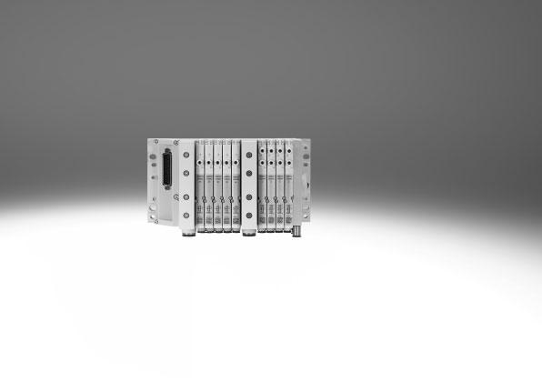
Valve terminals MPA-L
|
|
|
- Delphia Hines
- 6 years ago
- Views:
Transcription
1


2 Key features Innovative Versatile Reliable Easy to assemble Compact, high-performance valves in a sturdy metal housing Flow rates up to 870 l/min Wide range of electrical connection options for multi-pin plug: Sub-D, flat cable or terminal strip Connection to the electrical peripherals CPX with a wide range of communication options I-Port/IO-Link interface Freely configurable push-in connectors Modular system offering a range of configuration options Freely extendable system with individual sub-bases and modular tie rods Up to 32 solenoid coils Conversions and extensions possible at a later date Air supply can be extended by additional pressure zones via supply modules Wide range of pressures bar Wide range of valve functions High output reserves thanks to large pneumatic cross sections and venting with high flow rates Resilient thanks to high mechanical rigidity Lightweight and low-cost polymer components Fast troubleshooting thanks to LEDs on the valves Easy to service thanks to replaceable valves and electronic modules Manual override either non-detenting, detenting or secured against unauthorised activation (covered) Durable thanks to tried-and-tested piston spool valves Fast and reliable in-house assembly using individual components or delivered as a ready-to-install and tested unit Lower selection, ordering, installation and commissioning costs Secure mounting on wall or H-rail 2 Internet: Subject to change 2018/01
3 Key features Width 10 mm, 14 mm and 20 mm Reduced downtimes: LED signal status display Pneumatic interface to CPX CPX diagnostic interface for handheld devices Simple electrical connections Multi-pin plug, fieldbus connections Control block, CPX I-Port interface/io-link Quick mounting: Directly using screws or on an H-rail Safe: Operating voltage connection, outputs and valves can each be switched off separately Reliable operation: Non-detenting/detenting or covered manual override Adaptable: Selector in the end plate for defining the pilot air supply (internal or external) Space-saving: Slim valves and flat plate silencers Practical: Pre-assembled QS cartridge fittings Flexible: 32 valve positions/32 solenoid coils Modular: Pressure zone creation, additional exhaust and supply ports possible using supply module Equipment options Valve functions 5/2-way valve, single solenoid 5/2-way valve, double solenoid 2x 3/2-way valve, normally open 2x 3/2-way valve, normally closed 2x 3/2-way valve, 1x normally open, 1x normally closed 5/3-way valve, mid-position pressurised 5/3-way valve, mid-position closed 5/3-way valve, mid-position exhausted 2x 2/2-way valve, 1x normally closed, 1x normally closed, reversible 2x 2/2-way valve, normally closed 1x 3/2-way valve, normally closed, external compressed air supply 1x 3/2-way valve, normally open, external compressed air supply Manual pressure regulators All valves have the same compact dimensions with an overall length of 107 mm and a height of 55 mm. Special features Max. 32 valve positions/max. 32 solenoid coils Parallel, modular valve linking Electrical interlinking with integrated holding current reduction Any compressed air supply (max. 8 supply modules) Creation of pressure zones Modular, individually extendable tie rods Single valves or combinations of four valves Tubing size at each connection freely selectable Valve terminal selection Valve terminal configurator The appropriate MPA-L valve terminal can be chosen quickly and easily using the online catalogue. This includes a convenient valve terminal configurator, which makes it much simpler to order the right product. Online via: 2D/3D CAD data You can request the CAD data for a valve terminal you have configured. To do so, start the product search as described above. Go to the shopping basket and click on the CAD icon (compass). On the next page you can generate a 3D preview or request another data format of your choice by . The valve terminals are fully assembled according to your order specification and are individually tested. This reduces assembly and installation time to a minimum. You order a valve terminal MPA-L using the order code. Ordering system for MPA-L Internet: mpal Ordering system for CPX Internet: cpx Ordering system for CTEU Internet: cteu 2018/01 Subject to change Internet: 3
4 Key features Individual connection Valves on individual sub-bases can also be used for actuators further away from the valve terminal. The valves are screwed to an individual sub-base made from die-cast aluminium. The electrical connection is established using a standard 4-pin M8 plug (EN ). Further information Internet: vmpa1 Individual sub-base assembly 2 1 Mounting holes horizontal 2 Mounting holes vertical The individual sub-base for wall mounting is designed for integration into a system or machine. It can be mounted horizontally or vertically. 1 Multi-pin plug connection The signal flow from the controller to the valve terminal takes place via a pre-assembled or self-assembled multi-wire cable to the multi-pin plug connection, which substantially reduces installation time. The valve terminal can be equipped with max. 32 solenoid coils. This corresponds to 2 to 32 valves. Versions Sub-D connection Pre-assembled multi-pin cable Multi-pin cable for self-assembly Flat cable connection Terminal strip connection 4 Internet: Subject to change 2018/01
5 Key features Fieldbus connection via the CPX system An integrated fieldbus node manages communication with a higher-order PLC. This enables a space-saving pneumatic and electronic solution. Valve terminals with fieldbus interfaces can be configured with up to 32 sub-bases. The CPX terminal also enables the integration of digital and analogue electrical inputs and outputs, pressure sensors and controllers for pneumatic or electric positioning axes. A detailed description of the extensive functionality can be found in the documentation for the CPX terminal Internet: cpx Fieldbus protocols/cpx variants: PROFIBUS DP PROFINET INTERBUS DeviceNet CANopen CC-Link EtherNet/IP Front End Controller Remote I/O Modbus/TCP EtherCAT POWERLINK Sercos III Control block connection via the CPX system Controllers integrated in the Festo valve terminals enable the construction of stand-alone control units to IP65, without control cabinets. In the slave operating mode, these valve terminals can be used for intelligent preprocessing and are therefore ideal modules for designing decentralised intelligence. In the master operating mode, terminal groups can be designed with many options and functions that can autonomously control a medium-sized machine/system. Fieldbus connection via the CTEU system Communication with a higher-level PLC is managed by a fieldbus node mounted directly on the I-Port interface. Valve terminals with an I-Port interface can be configured with up to 32 sub-bases. A detailed description of the extensive functionality can be found in the documentation for the fieldbus modules CTEU/installation system CTEL Internet: cteu Fieldbus protocols: PROFIBUS DP DeviceNet CANopen CC-Link EtherCAT I-Port interface/io-link I-Port/IO-Link consists of a central master and the devices with I-Port interface/io-link connected via special connecting cables. This permits a decentralised layout of the devices. The connection type corresponds to a star topology. In other words, only one module or valve terminal can be connected to each I-Port. The I-Port interface from Festo is based on IO-Link and is compatible with IO-Link in certain areas. As well as communication, the I-Port interfaces also handle the power supply for the connected devices. The maximum length of a string is 20 m. 2018/01 Subject to change Internet: 5
6 Peripherals overview Modular pneumatic components The modular design of the MPA-L facilitates maximum flexibility right from the planning stage and offers maximum ease of servicing during operation. The system consists of sub-bases and valves. The sub-bases form the support system for the valves. They contain the connection ducts for supplying compressed air to and venting from the valve terminal as well as the working lines for the pneumatic drives for each valve. The sub-bases are joined together via a tie rod system. This consists of a threaded rod, threaded sleeve and screw. The threaded rod/sleeve combination is selected as appropriate to the chosen number of individual sub-bases. A valve terminal can be easily extended by adding individual sub-bases or supply modules. This is done by inserting suitable tie rod extenders between the threaded rod and sleeve. This ensures that the valve terminal can be rapidly and reliably extended. -H- Note The tie rod system for the valve terminal MPA-L consists of at least four sub-bases or two sub-bases and one supply module. Shorter valve terminals with two or more valve positions can be constructed without a sleeve. Modular electrical peripherals The mechanical connection between the CPX modules is established using tie rods. Two screws in the end plates are all that are needed to assemble the entire unit. The tie rod ensures that the unit resists high mechanical loads and is therefore the "mechanical backbone" of the CPX terminal. The open design allows interlinking blocks to be replaced in assembled state. The tie rod extension kit allows an extra module to be added to the CPX terminal. The input/output modules, connection blocks, fieldbus nodes or control block of the CPX system are mounted on the interlinking blocks using four screws and can be almost infinitely replaced or modified. 6 Internet: Subject to change 2018/01
7 Peripherals overview Individual sub-base Ordering: Using individual part numbers Individual sub-bases can be equipped with any valve (VMPA of the corresponding width). The electrical connection is established using a standard 4-pin M8 plug (EN ) aj Designation Brief description Page/Internet 1 Solenoid valve Width 10 mm, 14 mm, 20 mm VMPA1 2 Manual override (MO) Non-detenting/turning with detent, per solenoid coil VMPA1 3 Cover cap MO non-detenting only once cover cap fitted VMPA1 4 Cover cap MO blocked once cover cap fitted VMPA1 5 Cover cap MO detenting and can be operated without accessories once cover cap fitted VMPA1 6 Inscription label holder Can be pushed onto the manual override VMPA1 7 Sub-base For individual valve VMPA VMPA1 8 Fittings and/or silencers For working ports (2, 4) and air/exhaust ports (1, 3, 5) VMPA1 9 Fittings, silencers or blanking plugs For pilot air supply/pilot exhaust air (12/14, 82/84) and pressure compensation VMPA1 aj Electrical connection M8 4-pin VMPA1 2018/01 Subject to change Internet: 7
8 Peripherals overview Valve terminal Pneumatic components The sub-bases are available individually with one valve position or with four valve positions. The electrical interlinking modules are available for: 1 or 4 single solenoid valves 1 or 4 double solenoid valves Double solenoid valve positions can be fitted with any valve or a blanking plate. Single solenoid valve positions can only be fitted with single solenoid valves or a blanking plate aj aa 3 ab 2 1 bf be ad ac ae bb ba bj ai ah ag af bd bc 3 8 Internet: Subject to change 2018/01
9 Peripherals overview Valve terminal Pneumatic components Designation Brief description Page/Internet 1 Plate Exhaust plate as flat plate silencer 60 2 Plate Exhaust plate for ducted exhaust air 60 3 Cartridge fitting For supply and exhaust ports 63 4 Cover cap for manual override Conversion from detenting/non-detenting to non-detenting or detenting or covered or 59 inscription label holder 5 Solenoid valve Single solenoid 49 6 Electrical interlinking module, 4-way Electrical interlinking module for combination of four sub-bases, single solenoid/double 52 solenoid 7 Mounting bracket Mounting bracket for wall mounting 59 8 Regulator plate Vertical stacking (pressure regulator, vertical pressure shut-off plate, vertical supply plate) 50 9 Pressure gauge Can be optionally mounted on a pressure regulator plate 50 aj Right-hand end plate, low End plate with pilot air selector, with ports 12/14, 82/84 61 aa Screw Tie rod system, connects the sub-bases 58 ab Right-hand end plate, high End plate with pilot air selector, with ports 1, 3, 5, 12/14, 82/84 61 ac Inscription label 6 x 10 mm 59 ad Holder for inscription label 59 ae Sub-base Four individual sub-bases screwed together to form one unit 52 af Sleeve Tie rod system, connects the sub-bases 58 ag Tie rod extender For subsequent modular extension of the valve terminal 58 ah Tie rod Threaded rod, clamps the sub-bases between the end plates 58 ai Cartridge fitting For working lines 63 bj Sub-base, individual Sub-base with one valve position 52 ba Electrical interlinking module Electrical interlinking module for single sub-base, single solenoid/double solenoid 52 bb Clamp strap for cartridge fitting bc Supply module For compressed air supply/exhaust air 60 bd Electrical interlinking module Electrical interlinking module for supply module, signals are passed through 52 be Restrictor Fixed restrictor for installation in duct 3 or 5 of the sub-base 51 bf Retainer for restrictor Required to install the fixed restrictor /01 Subject to change Internet: 9
10 Peripherals overview Valve terminal with multi-pin plug connection Order code: 34P- MPA-L valve terminals with multi-pin plug connection can be expanded by up to 32 solenoid coils/valve positions. The multi-pin plug connection is removable and designed as a 9, 25 or 44-pin Sub-D connection. The multi-pin plug connection can alternatively be ordered as a terminal strip (33-pin) or flat cable connection (40-pin). The Sub-D multi-pin plug connection, 25 and 44-pin, is available in IP40 and IP67 or with multi-pin plug cover, without connecting cable, with a choice of cable outlet to the side or front. Sub-D multi-pin plug connection, 25 and 44-pin, with multi-pin plug cover with pre-assembled cable: 2.5 m 5 m 10 m Variable, up to 30 m Designation Brief description Page/Internet 1 Multi-pin plug connection Terminal strip, 33-pin, IP Multi-pin plug connection For flat cable, 40-pin, IP Multi-pin plug connection Sub-D, 25-pin 61 4 Multi-pin plug connection Sub-D, 9-pin, IP Connecting cable With cover, pre-assembled, connection on side, IP Cover For self-assembly, connection on side, IP Cover For self-assembly, connection on front, IP Connecting cable With cover, pre-assembled, connection on front, IP Internet: Subject to change 2018/01
11 Peripherals overview Valve terminal with fieldbus connection, control block (electrical peripherals CPX) Order code: 34P- for the pneumatic components 50E- for the electrical peripherals Valve terminals with CPX interface can be expanded by up to 32 solenoid coils/valve positions. Up to 32 valve positions can be equipped in combination with single solenoid valves; the maximum number of valve positions is reduced to 16 if only double solenoid valves are used. The maximum number of addresses is set in the range 4 32 solenoid coils via a selector switch. This enables extensions to be pre-assigned in a control program and called up by means of manual settings. Each valve position can be equipped with any valve or a blanking plate. The rules for CPX apply to the equipment that can be used in combination with the electrical peripherals CPX. In general: Digital inputs/outputs Analogue inputs/outputs Parameterisation of inputs and outputs Integrated multi-featured diagnostic system Preventive maintenance concepts Designation Brief description Page/Internet 1 CPX modules Fieldbus node, control block, input and output modules cpx 2 Left-hand end plate Pneumatic interface for CPX terminal 61 3 Inscription label Large, for left-hand end plate/pneumatic interface for CPX terminal 4 H-rail mounting /01 Subject to change Internet: 11
12 Peripherals overview Valve terminal with I-Port interface/io-link (and fieldbus node) Order code: 34P- for the pneumatic components CTEU- for the fieldbus node Valve terminals with I-Port interface/io-link can be expanded by up to 32 solenoid coils/valve positions. Up to 32 valve positions can be equipped in combination with single solenoid valves. The maximum number of valve positions is reduced to 16 if only double solenoid valves are used. Each valve position can be equipped with any valve or a blanking plate Designation Brief description Page/Internet 1 Fieldbus node CTEU Fieldbus node cteu 2 Plug For I-Port interface/io-link sea 3 T-adapter For I-Port interface/io-link fb-ta 5 Connecting cable Between two I-Port interfaces nebv 6 Electrical sub-base With bus node for connecting two devices with I-Port interfaces cteu 7 H-rail mounting For electrical sub-base cteu 8 Left-hand end plate End plate with I-Port interface/io-link Internet: Subject to change 2018/01
13 Key features Pneumatic components Sub-base valve MPA-L offers a comprehensive range of valve functions. All valves are equipped with piston spool and patented sealing system that facilitates efficient sealing, a broad pressure range and long service life. They have a pneumatic pilot control for optimising performance. Air is supplied by means of pilot air supply. Sub-base valves can be quickly replaced since the tubing connectors remain on the sub-base. This design is also particularly slim. Irrespective of the valve function there are sub-base valves with one solenoid coil (single solenoid) or with two solenoid coils (double solenoid or two single solenoid valves in one housing). Design Valve replacement The valves are attached to the sub-base using two screws, which means that they can be easily Extension replaced. The mechanical sturdiness of the sub-base guarantees good long-term sealing. Blanking plates can be replaced by valves at a later date. The dimensions, mounting points and existing pneumatic installations remain unchanged during this process. The valve code (e.g. M, J, N, NS, NU, etc.) is located on the front of the valve beneath the manual override. -H- Note A filter must be installed upstream of valves operated in vacuum mode. This prevents any foreign matter in the intake air getting into the valve (e.g. when operating a suction cup). 5/2-way valve Circuit symbol Code Description Position function 1-32: M Single solenoid Pneumatic spring return Reversible Operating pressure bar Available in width 10 mm, 14 mm and 20 mm Position function 1-32: MS Single solenoid Mechanical spring return Reversible Operating pressure bar Available in width 10 mm, 14 mm and 20 mm Position function 1-32: MU Single solenoid Polymer poppet valve Mechanical spring return Reversible Operating pressure bar Available in width 10 mm Position function 1-32: J Double solenoid Reversible Operating pressure bar Available in width 10 mm, 14 mm and 20 mm 2018/01 Subject to change Internet: 13
14 Key features Pneumatic components 2x 3/2-way valve Circuit symbol Code Description Position function 1-32: N Single solenoid Normally open Pneumatic spring return Operating pressure 3 10 bar Available in width 10 mm, 14 mm and 20 mm Position function 1-32: NS Single solenoid Normally open Mechanical spring return Reversible Operating pressure bar Available in width 10 mm, 14 mm and 20 mm Position function 1-32: NU Single solenoid Polymer poppet valve Normally open Mechanical spring return Reversible Operating pressure bar Available in width 10 mm Position function 1-32: K Single solenoid Normally closed Pneumatic spring return Operating pressure 3 10 bar Available in width 10 mm, 14 mm and 20 mm Position function 1-32: KS Single solenoid Normally closed Mechanical spring return Reversible Operating pressure bar Available in width 110 mm, 14 mm and 20 mm Position function 1-32: KU Single solenoid Polymer poppet valve Normally closed Mechanical spring return Reversible Operating pressure bar Available in width 10 mm Position function 1-32: H Single solenoid Normal position 1x closed 1x open Pneumatic spring return Operating pressure 3 10 bar Available in width 10 mm, 14 mm and 20 mm Position function 1-32: HS Position function 1-32: HU Single solenoid Normal position 1x closed 1x open Mechanical spring return Single solenoid Polymer poppet valve Normal position 1x closed 1x open Reversible Operating pressure bar Available in width 10 mm, 14 mm and 20 mm Mechanical spring return Reversible Operating pressure bar Available in width 10 mm 14 Internet: Subject to change 2018/01
15 Key features Pneumatic components 5/3-way valve Circuit symbol Code Description Position function 1-32: B Mid-position pressurised 1) Mechanical spring return Reversible Operating pressure bar Available in width 10 mm, 14 mm and 20 mm Position function 1-32: G Mid-position closed 1) Mechanical spring return Reversible Operating pressure bar Available in width 10 mm, 14 mm and 20 mm Position function 1-32: E Mid-position exhausted 1) Mechanical spring return Reversible Operating pressure bar Available in width 10 mm, 14 mm and 20 mm 1) If neither solenoid coil is energised, the valve moves to its mid-position by means of spring force. If both coils are energised at the same time, the valve remains in the previously assumed switching position. 3/2-way valve Circuit symbol Code Description Position function 1-32: W Single solenoid Normally open External compressed air supply Pneumatic spring return Reversible Operating pressure bar Position function 1-32: X Single solenoid Normally closed External compressed air supply Pneumatic spring return Reversible Operating pressure bar Available in width 10 mm, 14 mm and 20 mm Compressed air ( bar) supplied at working line 2 can be switched with both internal and external pilot air supply. Available in width 10 mm, 14 mm and 20 mm Compressed air ( bar) supplied at working line 4 can be switched with both internal and external pilot air supply. 2x 2/2-way valve Circuit symbol Code Description Position function 1-32: D Single solenoid Normally closed Pneumatic spring return Operating pressure 3 10 bar Available in width 10 mm, 14 mm and 20 mm Position function 1-32: DS Single solenoid Normally closed Mechanical spring return Reversible Operating pressure bar Available in width 10 mm, 14 mm and 20 mm Position function 1-32: I Single solenoid 1x normally closed 1x normally closed, reversible Pneumatic spring return Operating pressure 3 10 bar Vacuum at port 3/5 only Available in width 10 mm, 14 mm and 20 mm 2018/01 Subject to change Internet: 15
16 Key features Pneumatic components Blanking plate Blanking plate (code L) without valve function, for reserving valve positions on a valve terminal. Valves and blanking plates are attached to the sub-base using two screws. Exhaust functions Fixed restrictor The fixed restrictor can be used to permanently set the exhaust flow rate in ducts 3 and 5. Assembly: Press the retainer as far as it will go into the exhaust openings on the sub-base Screw the fixed restrictor into the retainer Mount the valve on the sub-base The restrictor cuts a thread into the retainer as it is screwed in. For that reason, the retainer should also be changed when a restrictor is repeatedly replaced. The restrictor is available in 7 different nominal sizes ( mm). The individual sizes are colour-coded for ease of identification. Fixed restrictors enable, for example, the cylinder speed to be set to a predefined limit in response to known flow rate conditions. They cannot be accessed during operation and are therefore protected against manipulation. This is beneficial in the production of standard machines since the required speed can be determined once and the installation simply duplicated for further machines, saving time and costs for repeated commissioning. -H- Note The fixed restrictors are available only for valves or manifold sub-bases of size 10 mm. Non-return valve The non-return valves prevent the air from being pushed back (back pressure) from the ducts 3 and 5 into the solenoid valve. This prevents the back pressure from having a disruptive effect on other connected actuators. The non-return valves are integrated into ducts 3 and 5 of the sub-bases. The non-return valves should be installed according to the specifications using the enclosed assembly tool. Following assembly, the non-return valves cannot be removed. Please see the relevant assembly instructions: -H- Note Pre-assembled sub-bases with integrated non-return valves are available. It is not possible to use a nonreturn valve and a fixed restrictor (in the same duct) at the same time. 16 Internet: Subject to change 2018/01
17 Key features Pneumatic components Vertical stacking Additional functions can be added to each valve position between the sub-base and the valve. These functions are known as vertical stacking modules and enable special functioning or control of an individual valve position. Pressure regulator plate An adjustable pressure regulator can be installed between the sub-base and the valve in order to control the force of the triggered actuator. This pressure regulator maintains an essentially constant output pressure (secondary side) independent of pressure fluctuations (primary side) and air consumption. Standard version: For supply pressure up to 6 bar or up to 10 bar Without pressure gauge (optional, rotatable) Adjusted using a screwdriver or regulator knob Vertical pressure shut-off plate for width 10 mm The vertical pressure shut-off plate can be used to hot swap individual valves without switching off the overall air supply. The working pressure for the individual valve can be switched off manually via the vertical pressure shut-off plate using the actuating element. Vertical pressure supply plate for width of 20 mm This vertical pressure supply plate enables an individual valve to be supplied with individual operating pressure independently of the operating pressure of the valve terminal. The exhaust and pilot air supply of the valve are still provided via the central connections of the valve terminal. 2018/01 Subject to change Internet: 17
18 Key features Pneumatic components Pressure regulator Circuit symbol Code Description Pressure regulator 1-32: PA Pressure regulator 1-32: PF Regulates the pressure upstream of the valve in duct 1 Same regulated pressure at duct 2 and duct 4 Venting in the valve from duct 2 to duct 3 and from duct 4 to duct 5 Regulator not affected by venting Regulator can always be adjusted Available in width 10 mm and 20 mm Pressure regulator 1-32: PC Pressure regulator 1-32: PH Regulates the pressure for duct 2 downstream of the valve Venting via the regulator from duct 2 to duct 3 Exhaust flow rate is restricted by the regulator Regulator can only be adjusted in switched state Available in width 10 mm and 20 mm Pressure regulator 1-32: PB Pressure regulator 1-32: PG Regulates the pressure for duct 4 downstream of the valve Venting via the regulator from duct 4 to duct 5 Exhaust flow rate is restricted by the regulator Regulator can only be adjusted in switched state Available in width 10 mm and 20 mm Pressure regulator 1-32: PN Pressure regulator 1-32: PL Splits the supply air in duct 1 and regulates the pressure upstream of the valve in duct 3 Valve is operated in reverse mode Venting in the valve from duct 2 to duct 1 Regulator not affected by venting Regulator can always be adjusted Available in width 20 mm Pressure regulator 1-32: PK Pressure regulator 1-32: PM Splits the supply air in duct 1 and regulates the pressure upstream of the valve in duct 5 Valve is operated in reverse mode Venting in the valve from duct 4 to duct 1 Regulator not affected by venting Regulator can always be adjusted Available in width 20 mm Vertical pressure shut-off plate Circuit symbol Code Description Pressure regulator 1-32: PS Allows the pressure in duct 1 and duct 12/14 to be switched off upstream of the valve Venting in the valve from duct 2 to duct 3 and from duct 4 to duct 5 Vertical pressure shut-off plate not affected by venting Operating pressure 3 8 bar Available in width 10 mm 18 Internet: Subject to change 2018/01
19 Key features Pneumatic components Vertical pressure supply plate Circuit symbol Code Description Pressure regulator 1-32: PV Enables separate supply of the pressure in duct 1 and upstream of the valve Operating pressure bar Available in width of 20 mm Compressed air supply and venting Supply module Right-hand end plate The valve terminal MPA-L can be supplied with compressed air at one or more points via supply modules and/or the right-hand end plate. The generously sized pneumatic system enables good performance from all functional components, even with large-scale expansions. Venting (ducts 3 and 5) either takes place via silencers or ports for ducted exhaust air via the supply modules or the right-hand end plate. There are two types of supply module with venting: Exhaust air 3/5 via flat plate silencer Exhaust air 3/5 ducted Venting (ducts 3 and 5) can alternatively or additionally take place via the right-hand end plate. Ducts 3 and 5 are separate in the terminal and are only joined together in the supply module. The exhaust air from the pilot air (duct 82/84) is entirely separate from ducts 3 and 5. Pilot air supply The valve terminal MPA-L is supplied with pilot air exclusively via the right-hand end plate. The pilot air supply can be selected at the pilot air selector on the end plate: Internal (from duct 1) or External (from duct 12/14) Switching position for internal, marked "Int" Internal pilot air supply can be selected if the supply pressure for the terminal is between 3 and 8 bar. In this case, the pilot air supply is branched by means of an internal connection from duct 1 in the right-hand end plate. Port 12/14 on the right-hand end plate can be sealed using a blanking plug. Switching position for external, marked "Ext" If the supply pressure (at the right-hand end plate) is less than 3 bar or greater than 8 bar, then the valve terminal MPA-L must be operated with an external pilot air supply. The pilot air supply is then fed via port 12/14 on the right-hand end plate. When using several pressure zones, the supply pressure in the pressure zone with the right-hand end plate is decisive. -H- Note If a gradual pressure build-up in the system using a soft-start valve is chosen, an external pilot air supply should be connected so that the control pressure applied during switch-on is already very high. 2018/01 Subject to change Internet: 19
20 Key features Pneumatic components Compressed air supply and pilot air supply Graphical illustration Code Notes Right-hand end plate, with supply ports Right-hand end plate: D Pilot air: Internal pilot air supply Pilot air is branched internally from port 1 in the right-hand end plate Exhaust air 3/5 via right-hand end plate or supply module Pilot exhaust air 82/84 via right-hand end plate For operating pressure in the range 3 8 bar Right-hand end plate: D Pilot air: E External pilot air supply Pilot air supply (3 8 bar) is connected at the right-hand end plate at port 12/14 Exhaust air 3/5 via right-hand end plate or supply module Pilot exhaust air 82/84 via right-hand end plate For operating pressure in the range bar (suitable for vacuum) Right-hand end plate, without supply ports Right-hand end plate: Pilot air: Right-hand end plate: Pilot air: E Internal pilot air supply Pilot air is branched internally from port 1 in the right-hand end plate Exhaust air 3/5 via supply module Pilot exhaust air 82/84 via right-hand end plate For operating pressure in the range 3 8 bar External pilot air supply Pilot air supply (3 8 bar) is connected at the right-hand end plate at port 12/14 Exhaust air 3/5 via supply module Pilot exhaust air 82/84 via right-hand end plate For operating pressure in the range bar (suitable for vacuum) Supply module, flat plate silencer Type of module block 1-40: U Exhaust port: Exhaust air 3/5 via flat plate silencer Pilot exhaust air 82/84 via right-hand end plate For operating pressure in the range bar (suitable for vacuum) Supply module, ducted exhaust air Type of module block 1-40: U Exhaust port: UD, UE, UF, UM, UN, UP or UG Exhaust air 3/5 via supply module Pilot exhaust air 82/84 via right-hand end plate For operating pressure in the range bar (suitable for vacuum) 20 Internet: Subject to change 2018/01
21 Key features Pneumatic components Supply module Illustration Code Type Designation Notes Exhaust port: UD, UE, UF, UM, UN, UP or UG VMPAL-EG Exhaust plate for ducted exhaust air Exhaust port: VMPAL-EU Flat plate silencer Type of module block 1-40: U VMPAL-SP-0 Supply module with electrical interlinking module Additional supply modules can be used for larger terminals or to create additional pressure zones. Supply modules can be configured at any point upstream or downstream of the sub-bases. Supply modules contain the following ports: Compressed air supply (duct 1) Exhaust air (duct 3/5) Depending on your order, the exhaust ducts are either ducted or vented via the flat plate silencer. Ports for supply and venting Code Port Push-in fitting/cartridge fitting Right-hand end plate with supply ports 1, 3, 5 Right-hand end plate: D 1 Air/vacuum supply Thread G1/4 Push-in fitting, straight or angled, 3 Exhaust air Thread G1/4 for tubing O.D. 8 mm, 10 mm, 12 mm, 5/16", 3/8" 5 Exhaust air Thread G1/4 12/14 82/84 Pilot air supply Pilot exhaust air Thread M7 Thread M7 Push-in fitting, straight or angled, for tubing O.D. 4 mm, 6 mm Push-in fitting, straight, for tubing O.D. 3/16", 1/4" Supply module Type of module block 1-40: U 1 Air/vacuum supply Cartridge fitting Cartridge fitting, straight, for tubing O.D. 8 mm, 10 mm, 12 mm, 5/16", 3/8", 1/2", adapter for thread G1/4 3/5 Exhaust air Flat plate silencer Cartridge fitting Cartridge fitting, straight, for tubing O.D. 8 mm, 10 mm, 12 mm, 5/16", 3/8", 1/2", adapter for thread G1/4 12/14 Pilot air supply 82/84 Pilot exhaust air Right-hand end plate without supply ports Right-hand end plate: 1 Air/vacuum supply 3 Exhaust air 5 Exhaust air 12/14 82/84 Pilot air supply Pilot exhaust air Thread M7 Thread M7 Push-in fitting, straight or angled, for tubing O.D. 4 mm, 6 mm Push-in fitting, straight, for tubing O.D. 3/16", 1/4" 2018/01 Subject to change Internet: 21
22 Key features Pneumatic components Creating pressure zones and separating exhaust air MPA-L offers a number of options for creating pressure zones if different working pressures are required. Up to 20 pressure zones in total are possible. Pressure zones are created by isolating the internal supply ducts in a special sub-base. Each pressure zone must have its own compressed air supply. Compressed air can be supplied and vented via a supply module and/or the right-hand end plate. The position of the supply modules and the sub-bases with pressure zone separation can be freely chosen with the valve terminal MPA-L. The sub-bases with pressure zone separation are integrated in the terminal ex-works as per your order. They can be distinguished by their coding, even when the valve terminal is assembled. Duct separation always takes place to the right of the sub-base. Creating pressure zones Sub-bases with pressure zone separation Code Notes Illustrated examples Coding Duct separation to the No duct separation right of sub-base 1-40: Duct separation to the right of sub-base 1-40: T Duct 1 separated VMPAL- -T1 Duct separation to the right of sub-base 1-40: TR Duct 3/5 separated VMPAL- -T35 Duct separation to the right of sub-base 1-40: TS Ducts 1 and 3/5 separated VMPAL- -T Internet: Subject to change 2018/01
23 Key features Pneumatic components Examples: Compressed air supply and pilot air supply Internal pilot air supply, right-hand end plate without supply ports The illustration opposite shows an example of the configuration and connection of the air supply with internal pilot air supply. The exhaust air (duct 3/5) is discharged via supply modules. The pilot exhaust air (duct 82/84) is discharged via the right-hand end plate. Special sub-bases are used to create pressure zones. External pilot air supply, right-hand end plate without supply ports The illustration opposite shows an example of the configuration and connection of the compressed air supply with external pilot air supply. Port 12/14 on the right-hand end plate is equipped with a fitting for this. The exhaust air (duct 3/5) is discharged via supply modules. The pilot exhaust air (duct 82/84) is discharged via the right-hand end plate. Special sub-bases are used to create pressure zones. 2018/01 Subject to change Internet: 23
24 Key features Pneumatic components Sub-base MPA-L is based on a modular system consisting of sub-bases and valves. The sub-bases are connected together using tie rods and thus form the support system for the valves. They contain the connection ducts for supplying compressed air to and venting from the valve terminal as well as the working lines for the pneumatic drives for each valve. The sub-bases are joined together via tie rods. The tie rod consists of a threaded rod, threaded sleeve and screw. In principle, sub-bases have a modular structure. If this modularity is not required within a terminal, then four individual sub-bases can be combined with a 4-way electrical interlinking module to save costs. The threaded rod/sleeve combination is selected as appropriate to the number and width of the individual sub-bases or sub-base combination. To add further blocks, simply loosen the tie rod and adapt with extenders. There are no restrictions on extensions; a tie rod could be made almost entirely from extenders. Sub-base variants Graphical illustration Code Type Notes VMPAL-AP-10 VMPAL-AP-14 VMPAL-AP-20 Combination manifold block: Z VMPAL-AP- -QS -1 VMPAL-AP- -QS -2 Without cartridge Without electrical interlinking module With cartridge (push-in connector for compressed air tubing with standard O.D.) With electrical interlinking module With/without duct separation VMPAL-AP- -T1 Duct separation in duct 1 With/without cartridge (push-in connector for compressed air tubing with standard O.D.) With/without electrical interlinking module With/without non-return valve in duct 3 and 5 VMPAL-AP- -T35 Duct separation in ducts 3 and 5 Without electrical interlinking module With/without non-return valve in duct 3 and 5 VMPAL-AP- -T135 Duct separation in ducts 1, 3 and 5 Without electrical interlinking module With/without non-return valve in duct 3 and 5 VMPAL-AP- -RV With non-return valve in duct 3 and 5 Without electrical interlinking module With/without duct separation VMPAL-AP-4x10 VMPAL-AP-4x14 Four-valve block, not suitable for pressure zone separation No duct separation With/without electrical interlinking module With/without cartridge 24 Internet: Subject to change 2018/01
25 Key features Pneumatic components Electrical interlinking module Illustration Code Type No. of solenoid coils (valve positions) Notes Type of module block 1-40: A Type of module block 1-40: E Type of module block 1-40: B Type of module block 1-40: C Type of module block 1-40: F Type of module block 1-40: D Type of module block 1-40: A Type of module block 1-40: E Type of module block 1-40: C Type of module block 1-40: F Type of module block 1-40: U VMPAL-EVAP VMPAL-EVAP VMPAL-EVAP VMPAL-EVAP (1), double solenoid 1 (1), single solenoid Each solenoid coil must be assigned to a specific pin of the multi-pin plug for the valve to be actuated. Regardless of whether blanking plates or valves are used, valve positions occupy one coil/address (single solenoid valves) two coils/addresses (double solenoid valves) VMPAL-EVAP The electrical interlinking modules are colour-coded: Single solenoid grey Double solenoid black VMPAL-EVAP VMPAL-EVAP VMPAL-EVAP VMPAL-EVAP (4), double solenoid 4 (4), single solenoid Each solenoid coil must be assigned to a specific pin of the multi-pin plug for the valve to be actuated. Regardless of whether blanking plates or valves are used, valve positions occupy one coil/address (single solenoid valves) two coils/addresses (double solenoid valves) The electrical interlinking modules are colour-coded: VMPAL-EVAP Single solenoid grey Double solenoid black VMPAL-EVAP-20-SP Electrical interlinking module for power supply module 2018/01 Subject to change Internet: 25
26 Key features Assembly Valve terminal assembly Sturdy terminal assembly thanks to: Four through-holes for wall mounting Additional mounting brackets H-rail mounting -H- Note If the terminal is subject to strong vibrations or shock loads, use additional mounting brackets of the type VMPAL-BD for wall mounting. These should be attached to the valve terminal every 13 cm (one mounting bracket every 10 valve positions). Wall mounting Multi-pin plug connection The MPA-L valve terminal is screwed onto the mounting surface using four M4 or M6 screws. The mounting holes are on the multi-pin plug connection and on the right-hand end plate. Optional mounting brackets are also available. Wall mounting Fieldbus connection (CPX terminal) The MPA-L valve terminal is screwed onto the mounting surface using four M4 and two M6 screws or using six M6 screws. The mounting holes are on the left-hand and right-hand end plate and on the pneumatic interface. Optional mounting brackets are also available. H-rail mounting A B The MPA-L valve terminal is attached to the H-rail (see arrow A). The terminal is then swivelled onto the H-rail and secured in place with the clamping component (see arrow B). The following MPA-L mounting kit is required for H-rail mounting of the valve terminal: With multi-pin plug connection: CPX-CPA-BG-NRH With fieldbus connection (CPX terminal): VMPAF-FB-BG-NRH This enables mounting of the valve terminal on an H-rail to EN H- Note The mounting kits (see above) only lock the valve terminal in horizontal mounting position. 26 Internet: Subject to change 2018/01
27 Key features Assembly Tie rod Design Threaded rod 2 Tie rod extender 3 Sleeve 4 Screw Mode of operation The tie rod for MPA-L consists of four parts: Threaded rod Tie rod extender Sleeve Screw This enables valve terminals of any length to be created. The tie rod and valve terminal are assembled in just four steps: Screw the threaded rods to the left-hand end plate Screw the sleeves to the threaded rods Push the sub-bases and supply modules onto the rod/sleeve combination Push on the right-hand end plate and secure with screws that engage into the sleeves The tie rod enables subsequent extension of the valve terminal. This is done by loosening the tie rod screws and disassembling the relevant components. The additional sub-base or supply module is inserted at the required location. The previously disassembled components are then re-assembled. To compensate for the change in length, the tie rod must be extended by the increase in length. This is done by screwing in extenders between the threaded rod and sleeve. There are suitable extenders for each sub-base, combination of four sub-bases and supply module. 2018/01 Subject to change Internet: 27
28 Key features Assembly Tie rod Components and design Tie rod (threaded rod) Tie rod extender Sleeve Screw The threaded rod is used to create a cost-optimised fixed-grid tie rod. The threaded rod is required with valve terminal lengths exceeding mm, for example at least four sub-bases (10.7 mm each), since only the combination of a threaded rod and sleeve offers the optimum compensation of tolerances (by compressing the seals between the sub-bases). The valve terminal can be extended almost infinitely using tie rod extenders. The tie rod extenders are inserted between the threaded rod and sleeve and are available in appropriate lengths for sub-bases and supply modules. The primary purpose of the sleeve is to compensate tolerances that occur, for example, when the seals are compressed between the sub-bases during assembly. The sleeves come in different lengths, tailored to the use of a tie rod in a fixed grid as well as generally for the modular tie rods. The entire valve terminal is clamped via the tie rod using screws. Tolerances that occur, for example, when the seals are compressed between the sub-bases during assembly, are compensated by the interaction of the screws and sleeve. Individual modular tie rod Tie rods can be made entirely using tie rod extenders. The threaded rod and sleeve are required to compensate tolerances that occur, for example, when the seals are compressed between the sub-bases during assembly. Fixed-grid tie rod with extension The tie rod extenders are inserted between the threaded rod and sleeve. They are available in suitable lengths for sub-bases and supply modules. Fixed-grid tie rod The fixed-grid tie rod minimises assembly costs when assembling previously defined valve terminals. These valve terminals can be extended at any time. The threaded rod (and if applicable also the sleeve) must be replaced if the valve terminal length is reduced. Short valve terminal Valve terminals with a small number of valve positions are created by means of the following combinations: Width 10 mm Valve terminals with two valve positions and without a supply module are connected solely using screws Valve terminals with three valve positions and without a supply module (or with one valve position and one supply module) are connected using a 10 mm tie rod extender and screw Width 14 mm Valve terminals with two valve positions and without a supply module are connected using a 10 mm tie rod extender and screw 28 Internet: Subject to change 2018/01
29 Key features Assembly Ordering data Fixed-grid tie rod Reference length Part No. Type Part No. Type L = x V x W x Z x S Tie rod Sleeve VMPAL-ZAS VMPAL-ZAH VMPAL-ZAS VMPAL-ZAH VMPAL-ZAS VMPAL-ZAH VMPAL-ZAS VMPAL-ZAH VMPAL-ZAS VMPAL-ZAH VMPAL-ZAS VMPAL-ZAH VMPAL-ZAS VMPAL-ZAH VMPAL-ZAS VMPAL-ZAH VMPAL-ZAS VMPAL-ZAH VMPAL-ZAS VMPAL-ZAH VMPAL-ZAS VMPAL-ZAH VMPAL-ZAS VMPAL-ZAH VMPAL-ZAS VMPAL-ZAH VMPAL-ZAS VMPAL-ZAH VMPAL-ZAS VMPAL-ZAH VMPAL-ZAS VMPAL-ZAH VMPAL-ZAS VMPAL-ZAH VMPAL-ZAS VMPAL-ZAH VMPAL-ZAS VMPAL-ZAH VMPAL-ZAS VMPAL-ZAH VMPAL-ZAS VMPAL-ZAH VMPAL-ZAS VMPAL-ZAH VMPAL-ZAS VMPAL-ZAH VMPAL-ZAS VMPAL-ZAH VMPAL-ZAS VMPAL-ZAH VMPAL-ZAS VMPAL-ZAH VMPAL-ZAS VMPAL-ZAH VMPAL-ZAS VMPAL-ZAH VMPAL-ZAS VMPAL-ZAH VMPAL-ZAS VMPAL-ZAH VMPAL-ZAS VMPAL-ZAH VMPAL-ZAS VMPAL-ZAH VMPAL-ZAS VMPAL-ZAH VMPAL-ZAS VMPAL-ZAH VMPAL-ZAS VMPAL-ZAH VMPAL-ZAS VMPAL-ZAH VMPAL-ZAS VMPAL-ZAH VMPAL-ZAS VMPAL-ZAH VMPAL-ZAS VMPAL-ZAH VMPAL-ZAS VMPAL-ZAH VMPAL-ZAS VMPAL-ZAH VMPAL-ZAS VMPAL-ZAH VMPAL-ZAS VMPAL-ZAH VMPAL-ZAS VMPAL-ZAH VMPAL-ZAS VMPAL-ZAH VMPAL-ZAS VMPAL-ZAH VMPAL-ZAS VMPAL-ZAH VMPAL-ZAS VMPAL-ZAH-66 V W Z S Number of valve positions in width 10 mm Number of valve positions in width 14 mm Number of valve positions in width 20 mm Number of supply modules 2018/01 Subject to change Internet: 29
30 Key features Assembly Ordering data Fixed-grid tie rod Reference length Part No. Type Part No. Type L = x V x W x Z x S Tie rod Sleeve VMPAL-ZAS VMPAL-ZAH VMPAL-ZAS VMPAL-ZAH VMPAL-ZAS VMPAL-ZAH VMPAL-ZAS VMPAL-ZAH VMPAL-ZAS VMPAL-ZAH VMPAL-ZAS VMPAL-ZAH VMPAL-ZAS VMPAL-ZAH VMPAL-ZAS VMPAL-ZAH VMPAL-ZAS VMPAL-ZAH VMPAL-ZAS VMPAL-ZAH VMPAL-ZAS VMPAL-ZAH VMPAL-ZAS VMPAL-ZAH VMPAL-ZAS VMPAL-ZAH VMPAL-ZAS VMPAL-ZAH VMPAL-ZAS VMPAL-ZAH VMPAL-ZAS VMPAL-ZAH VMPAL-ZAS VMPAL-ZAH VMPAL-ZAS VMPAL-ZAH VMPAL-ZAS VMPAL-ZAH VMPAL-ZAS VMPAL-ZAH VMPAL-ZAS VMPAL-ZAH VMPAL-ZAS VMPAL-ZAH VMPAL-ZAS VMPAL-ZAH VMPAL-ZAS VMPAL-ZAH VMPAL-ZAS VMPAL-ZAH VMPAL-ZAS VMPAL-ZAH VMPAL-ZAS VMPAL-ZAH VMPAL-ZAS VMPAL-ZAH VMPAL-ZAS VMPAL-ZAH VMPAL-ZAS VMPAL-ZAH VMPAL-ZAS VMPAL-ZAH VMPAL-ZAS VMPAL-ZAH VMPAL-ZAS VMPAL-ZAH VMPAL-ZAS VMPAL-ZAH-46 V W Z S Number of valve positions in width 10 mm Number of valve positions in width 14 mm Number of valve positions in width 20 mm Number of supply modules 30 Internet: Subject to change 2018/01
31 Key features Display and operation Display and operation Signal status display Manual override Each solenoid coil is allocated an LED that indicates its signal status. Indicator 12 shows the signal status of the coil for duct 2 Indicator 14 shows the signal status of the coil for duct 4 The manual override (MO) enables the valve to be actuated when not electrically activated or energised. The valve is switched by pushing the manual override. Alternatives: A cover cap (code N, code y or as accessory) enables the manual override to be actuated by pressing it using an appropriate tool. A cover cap (code V) can be fitted over the manual override to prevent it from being accidentally actuated. Pneumatic connection and control elements Flat plate silencer, duct 3/5 2 Manual override (for each pilot solenoid coil, non-detenting or non-detenting/detenting) 3 Ducted exhaust air, duct 3/5 4 Ports 12/14 for external pilot air supply and 82/84 for pilot exhaust air in the right-hand end plate (depending on version also ducts 1, 3 and 5) 5 Supply port, duct 1 6 Working lines, ducts 2 and 4, for each valve position -H- Note A valve actuated manually (by means of the manual override) cannot be reset electrically. Conversely, an electrically actuated valve cannot be reset using the manual override. Manual override (MO) MO with automatic return (non-detenting) Press in the stem of the MO with a pointed object or screwdriver. Pilot valve switches and actuates the main valve. 2 Remove the pointed object or screwdriver. Spring force pushes the stem of the MO back. Pilot valve returns to its initial position and so too the single solenoid main valve (not with double solenoid valve code J). MO set via turning (detenting) Press in the stem of the MO with a pointed object or screwdriver until the valve switches and then turn the stem clockwise by 90 until the stop is reached. Valve remains switched. 2 Turn the stem anti-clockwise by 90 until the stop is reached and then remove the pointed object or screwdriver. Spring force pushes the stem of the MO back. Valve returns to its initial position (not with double solenoid valve code J). 2018/01 Subject to change Internet: 31
32 Key features Electrical components Manual override (MO) MO with cover cap, non-detenting Manual override is actuated by pushing it with a pointed object or screwdriver and reset by spring force (detenting position prevented due to cover cap). MO with cover cap, detenting without accessories, mounting Clip cover onto pilot valve. The MO is then actuated by moving the slide on the cover cap. MO with cover cap, detenting without accessories, actuation Moving the slide on the cover cap in the direction of the arrow has the following effect: Slide locks into the end position Pilot valve switches and actuates the main valve Moving the slide on the cover cap in the direction of the arrow has the following effect: Slide locks into the end position Spring force pushes the stem of the MO back. Pilot valve returns to its initial position and so too the single solenoid main valve (not with double solenoid valve code J) Inscription system Inscription area approx. 20 x 45 mm ASLR-D-L1 approx. 20 x 10 mm A holder VMPAL-ST-AP-10 (Part No ) with inscription labels (Part No , IBS-6x10) can be mounted on each sub-base for labelling the valves. The inscription label holder ASLR D-L1 can be pushed onto the manual override. Large inscription labels can be attached to the pneumatic interface as an alternative or in addition to the smaller labels. IBS-6x10 VMPAL-ST-AP-10 Electrical power as a result of current reduction Power management Each solenoid coil is protected with a spark arresting protective circuit as well as against polarity reversal. All valve types are additionally equipped with integrated current reduction. MPA-L valves are supplied with operating voltage in the range V (24 V +/ 10%). 32 Internet: Subject to change 2018/01
33 Key features Electrical components Electrical connection Left-hand end plate The electrical connection for connecting the valves to a higher-level controller is located in the left-hand end plate. The different connection options can be easily switched by replacing the left-hand end plate, while the pneumatic connections remain as they are. The valves are switched by means of positive or negative logic (PNP or NPN). Mixed operation is not permitted. Guidelines on addressing for valves/solenoid coils The numbering of the addresses goes from left to right in ascending consecutive order. The following applies to the individual valve positions: address x for coil 14 and address x+1 for coil 12. Each sub-base/electrical interlinking module occupies a defined number of addresses/pins: For single solenoid valve: 1 For double solenoid valve: 2 For combination of four sub-bases for single solenoid valves: 4 For combination of four sub-bases for double solenoid valves: 8 -H- Note If a single solenoid valve is assembled on a double solenoid valve position, the second address (for coil 12) is also occupied and cannot be used. Left-hand end plate variants Illustration Code Type Max. no. of addresses Electrical multi-pin connection Electrical connection: MS1 Electrical connection: MS2 Electrical connection: MS3 Electrical connection: MS6 Electrical connection: MS8 Electrical connection: MF1 Protection class Notes VMPAL-EPL-SD25-IP40 24 IP40 Electrical connection via Sub-D, 25-pin VMPAL-EPL-SD9-IP40 8 IP40 Electrical connection via Sub-D, 9-pin VMPAL-EPL-SD44-IP40 32 IP40 Electrical connection via Sub-D, 44-pin VMPAL-EPL-SD25 24 IP67 Electrical connection via Sub-D, 25-pin VMPAL-EPL-SD44 32 IP67 Electrical connection via Sub-D, 44-pin VMPAL-EPL-FL40-IP40 32 IP40 Electrical connection via flat cable, 40-pin Electrical connection: MC VMPAL-EPL-KL33-IP40 32 IP40 Electrical connection via terminal strip, 33-pin Fieldbus connection/cpx terminal Electrical connection: CX VMPAL-EPL-CPX 32 IP67 Electrical connection via CPX interlinking module I-Port interface/io-link Electrical connection: LK VMPAL-EPL-IPO32 32 IP65 IP67 Electrical connection via M12, 5 pin, IO-Link Electrical connection: PT VMPAL-EPL-IPO32 32 IP65 IP67 Electrical connection via M12, 5 pin, I-Port interface 2018/01 Subject to change Internet: 33
34 Key features Electrical components Pin allocation for electrical multi-pin plug connection Sub-D plug, 9-pin Pin Address/coil Pin Address/coil V 1) -H- Note The drawing shows the view onto the pins of the Sub-D plug ) 0 V for positive switching control signals; connect 24 V for negative switching control signals; mixed operation is not permitted. Pin allocation for electrical multi-pin plug connection Sub-D plug, 25-pin Pin Address/coil Pin Address/coil V 1) -H- Note The drawing shows the view onto the pins of the Sub-D plug ) 0 V for positive switching control signals; connect 24 V for negative switching control signals; mixed operation is not permitted. Pin allocation for electrical multi-pin plug connection Sub-D plug, 44-pin Pin Address/coil Pin Address/coil Pin Address/coil n.c n.c n.c n.c n.c n.c V 1) V 1) V 1) V 1) H- Note n.c n.c. The drawing shows the view onto the pins of the Sub-D plug. 1) 0 V for positive switching control signals; connect 24 V for negative switching control signals; mixed operation is not permitted. 34 Internet: Subject to change 2018/01
35 Key features Electrical components Pin allocation for electrical multi pin-plug connection Flat cable, 40-pin Pin Address/coil Pin Address/coil Pin Address/coil V 1) V 1) V 1) V 1) V 1) V 1) H- Note V 1) V 1) The drawing shows the view onto the pins of the flat cable plug. The flat cable connection is established using plug connectors, in accordance with DIN EN : (NECU-FCG40-K). Internet: necu 1) 0 V for positive switching control signals; connect 24 V for negative switching control signals; mixed operation is not permitted. Pin allocation for electrical multi pin-plug connection Terminal strip, 33-pin Pin Address/coil Pin Address/coil Pin Address/coil V 1) H- Note The drawing shows the view onto the pins of the terminal strip. Cables with the following specifications can be connected: Cable cross section mm 2 Insulation 5 6 mm 1) 0 V for positive switching control signals; connect 24 V for negative switching control signals; mixed operation is not permitted. 2018/01 Subject to change Internet: 35
36 Key features Electrical components Fieldbus connection/cpx terminal All functions and features of the electrical peripherals CPX are permitted in connection with the CPX interface. This means: The valves and outputs are supplied via the system supply for the CPX terminal The valves can optionally be actuated or switched off separately from the outputs The pneumatic interface (left-hand end plate) serves as an adapter between the two current feeds. In the pneumatic interface, the serial signals from the CPX terminal are converted into parallel signals. The number of addresses (solenoid coils that can be connected) is set via a selector (rotary switch) on the pneumatic interface to between 4 32 solenoid coils. The default setting on delivery provides for 32 addresses. This enables extensions to be pre-assigned in a control program and called up by means of manual settings. After converting or extending the valve terminal, the number of output addresses occupied by the pneumatic components must be checked and if applicable adjusted. -H- Note More information can be found at: Internet: cpx I-Port interface/io-link The I-Port interface/io-link enables the valve terminal CPV to be connected to the following systems: I-Port master from Festo (CPX terminal, CECC) Fieldbus node CTEU from Festo IO-Link master The maximum distance between the I-Port/IO-Link master and valve terminal with I-Port interface/io-link is 20 m. The 5-pin connecting cables contain the power supply for the valves, separate from this is the power supply for the internal valve terminal electronics and the control signals. -H- Note More information can be found at: Internet: cteu Pin allocation I-Port interface/io-link Pin Designation 1 24 V DC supply voltage for electronics and inputs 2 24 V DC load voltage supply for valves and outputs 3 0 V DC supply voltage for electronics and sensors 4 Communication signal C/Q, data cable 5 0 V DC load voltage supply for valves and outputs 36 Internet: Subject to change 2018/01
37 Key features Electrical components Instructions for use Equipment Bio-oils Mineral oils Operate system equipment with unlubricated compressed air if possible. Festo valves and cylinders are designed so that, if used as designated, they will not require additional lubrication and will still achieve a long service life. The quality of compressed air downstream of the compressor must correspond to that of unlubricated compressed air. If possible, do not operate all of your system equipment with lubricated compressed air. The lubricators should, where possible, always be installed directly upstream of the actuator used. Unsuitable additional oil and too high an oil content in the compressed air reduce the service life of the valve terminal. Use Festo special oil OFSW-32 or the alternatives listed in the Festo catalogue (as specified in DIN HLP32; basic oil viscosity 32 CST at 40 C). When using bio-oils (oils which are based on synthetic or native ester, e.g. rapeseed oil methyl ester), the maximum residual oil content of 0.1 mg/m 3 must not be exceeded (see ISO Class 2). When using mineral oils (e.g. HLP oils to DIN 51524, parts 1 to 3) or similar oils based on poly-alpha-olefins (PAO), the maximum residual oil content of 5 mg/m 3 must not be exceeded (see ISO Class 4). A higher residual oil content irrespective of the compressor oil cannot be permitted, as the basic lubricant would be flushed out over time. 2018/01 Subject to change Internet: 37

38 Technical data -M- Flow rate Up to 870 l/min -K- Valve width 10 mm 14 mm 20 mm -P- Voltage 24 V DC General technical data Valve terminal design Modular, valve sizes can be mixed Electrical actuation Fieldbus Multi-pin plug IO-Link I-Port Type of actuation Electrical Nominal operating voltage [V DC] 24 Permissible voltage [%] ±25 fluctuations Max. no. of valve positions 32 Max. number of pressure zones 20 Valve size [mm] 10, 14, 20 Signal status display LED Pilot air supply Internal or external Lubrication Life-time lubrication, PWIS-free (free of paint-wetting impairment substances) Type of mounting Wall mounting On H-rail to EN Mounting position Any (wall mounting) Horizontal only (H-rail) Manual override Non-detenting, detenting Corrosion resistance class CRC 1) 3 Note on materials RoHS-compliant Degree of protection IP65, IP67 1) Corrosion resistance class 3 according to Festo standard Components subject to high corrosion stress. Externally visible parts with primarily functional surface requirements which are in direct contact with the surrounding industrial environment or media such as solvents and cleaning agents. Operating and environmental conditions Operating medium Compressed air to ISO :2010 [7:4:4] Note on operating/ Lubricated operation possible (in which case lubricated operation will always be required) pilot medium Operating pressure [bar] Pilot pressure [bar] 3 8 Ambient temperature [ C] Temperature of medium [ C] Storage temperature 1) [ C] Certification c UL us - Listed (OL) RCM trademark 1) Long-term storage 38 Internet: Subject to change 2018/01
Valve terminals MPA-L
 Key features Innovative Versatile Reliable Easy to assemble Compact, high-performance valves in a sturdy metal housing Flow rates up to 870 l/min Wide range of electrical connection options for multi-pin
Valve terminals MPA-F
 Key features Innovative Versatile Reliable Easy to mount Manifold blocks, tubing connections and exhausts designed for optimum flow rates Tubing diameters: Working ports up to 10 mm Supply ports up to
Valve Manifolds Type 44 VTSA, Type 45 VTSA-F Metric Series Overview
 Overview Modular multi-functional valve manifold for up to 3 valves: Type 44 VTSA, ISO 15407-/ISO 5599- Type 45 VTSA-F with optimized flow Different valve sizes on one valve manifold: 18 mm (ISO 0) 6 mm
Valve terminals MPA-S
 Key features Innovative Versatile Reliable Easy to mount Slim high-performance valves in sturdy metal housing MPA1 flow rates up to 360 l/min MPA2 flow rates up to 700 l/min From the individual valve to
Solenoid valves VMPA
 Key features Innovative Versatile Reliable Easy to mount Slim high-performance valves in a sturdy metal housing MPA1 (width 10 mm): flow rate up to 360 l/min MPA14 (width 14 mm): flow rate up to 670 l/min
Valve terminals MPA-S
 Key features Innovative Versatile Reliable Easy to mount Slim high-performance valves in sturdy metal housing MPA1 flow rates up to 360 l/min MPA2 flow rates up to 700 l/min From the individual valve to
Valve Manifolds Type 44 VTSA, Type 45 VTSA-F Inch Series Overview
 Overview Modular multi-functional valve manifold for up to 3 valves: Type 44 VTSA, ISO 15407-/ISO 5599- Type 45 VTSA-F with optimized flow Different valve sizes on one valve manifold: 0.71 in (ISO 0) 1.0
Valve terminals VTSA/VTSA-F, NPT
 Key features Innovative Versatile Reliable Easy to install High-performance valves in sturdy metal housing Four valve sizes on one valve terminal Standardised from the multi-pin plug to the fieldbus connection
Valve terminals VTSA/VTSA-F
 Key features Innovative Versatile Reliable Easy to mount High-performance valves in sturdy metal housing Four valve sizes on one valve terminal Standardised from the multi-pin plug to the fieldbus connection
Valve terminal MPA-C
 Key features Innovative Versatile Reliable Easy to assemble Ideal housing surface design ensures that cleaning agents can run off, thus significantly reducing time and effort spent on cleaning Flow rate
Solenoid valves VUVB/valve terminals VTUB, NPT
 Solenoid valves VUVB/valve terminals VTUB, NPT Solenoid valves VUVB/valve terminals VTUB, NPT Key features Innovative Versatile Reliable Easy to mount Valve terminal for a wide range of pneumatic applications
Solenoid valves VUVS/valve manifold VTUS, NPT
 Solenoid valves VUVS/valve manifold VTUS, NPT Solenoid valves VUVS/valve manifold VTUS, NPT Key features Innovative Versatile Reliable Easy to install A reliable, heavy-duty valve with a long service life
Valve terminals CPV, Compact Performance
 Key features Innovative Versatile Reliable Easy to mount Cubic design for exceptional performance and low weight Low installation and bus connection costs Ideal for decentralised machines and system structures,
Valve terminals CPV-SC, Smart Cubic
 Key features Innovative Versatile Reliable Easy to mount Small, compact valve terminal for a wide range of pneumatic applications Enormous flexibility during planning, assembly and operational use Multi-pin
Pneumatic valves VUWS/valve manifold VTUS
 Pneumatic valves VUWS/valve manifold VTUS -V- New VUWS-LT25, VTUS-25 Pneumatic valves VUWS/valve manifold VTUS Key features Innovative Versatile Reliable Easy to install A reliable, heavy-duty valve with
Pneumatic valves VUWS/valve manifold VTUS
 Pneumatic valves VUWS/valve manifold VTUS -V- New VUWS-LT25, VTUS-25 Pneumatic valves VUWS/valve manifold VTUS Key features Innovative Versatile Reliable Easy to install A reliable, heavy-duty valve with
VTSA Valve Terminal. The Highest Degree of Modularity. Info 242 US. VTSA Valves on Single Subbase. VTSA Terminal with Multipin Connection
 VTSA Valve Terminal The Highest Degree of Modularity VTSA Valves on Single Subbase Size 01 (26 mm) and Size 02 (18 mm) Flow rate: up to 1.0 Cv (1000 l/min) Terminal strip or M12 connector NPT and G (BSPP)
Solenoid valves VUVS/valve manifold VTUS, NPT
 Solenoid valves VUVS/valve manifold VTUS, NPT -V- New VUVS-LT25, VTUS-25 Solenoid valves VUVS/valve manifold VTUS, NPT Key features Innovative Versatile Reliable Easy to install A reliable, heavy-duty
Solenoid valves VUVB/valve terminals VTUB
 Solenoid valves VUVB/valve terminals VTUB Solenoid valves VUVB/valve terminals VTUB Key features Innovative Versatile Reliable Easy to mount Valve terminal for a wide range of pneumatic applications Standardised
Multitalented. Valve and valve terminal series VG. Compact and high flow rates!
 Valve and valve terminal series VG Compact and high flow rates! Multitalented. Highlights VUVG Compact and with high flow rates Can be expanded into a valve terminal with an individual connection 2x 3/2-way
Multi-talented. Valve and valve terminal series VG
 Valve and valve terminal series VG Multi-talented. Highlights VUVG Compact with high flow rate Can be used as an individual valve or mounted on a valve manifold. 2x 3/2 one valve body, two functions Simple
Valve terminal CPA, Compact Performance
 Key features Innovative Flexible Reliable Easy to assemble Compact valves in sturdy metal housing Patented electrical linking system for flexible expansion options Standardised system of electrical connection
Solenoid/pneumatic valves, ISO
 Solenoid/pneumatic valves, ISO 15407-1 q/w Worldwide: Superb: Easy: Festo core product range Covers 80% of your automation tasks Always in stock Festo quality at an attractive price Reduces procurement
A quick match. Your selection tool for choosing valves and valve terminals.
 A quick match Your selection tool for choosing valves and valve terminals. The valve series at a glance: From individual valves... Simple, cost-effective, expandable CPV VTUG with plug-in VUVS VUVG Valve
Valve terminal VTUG-...-M/VTUG-...-V
 Valve terminal VTUG-...-M/VTUG-...-V 2 Design 2. Standard valve terminal (straight connecting plate) 2 3 4 Festo AG & Co. KG Ruiter Straße 82 73734 Esslingen Germany +49 7 347-0 www.festo.com Brief description
Valve terminals VTUB-12
 Key features Innovative Versatile Reliable Easy to mount Cost-effective I-Port interface for fieldbus nodes (CTEU) IO-Link mode for direct connection to a higher-level IO-Link master Lower installation
Valve terminal CPA, Compact Performance
 Valve terminal CPA, Compact Performance Key features Innovative Flexible Reliable Easy to assemble Compact valves in sturdy metal housing Patented electrical linking system for flexible expansion options
Miniature Valves MH1. Extremely small, fast and versatile. Info 206
 Miniature Valves MH1 Extremely small, fast and versatile Info 206 MH1 Miniature Valves Benefits and Applications of the MH1 Miniature Valve The MH1 offers maximum reliability, even in constant operation
Control block VOFA with safety function
 Key features Innovative Versatile Reliable Easy to assemble Can be used for safe reversing of a hazardous movement (5/2-way solenoid valve) Can be used for safe venting (3/2-way solenoid valve function,
Valve terminals type 03 VIMP-/VIFB-03, multi-functional MIDI/MAXI
 Key features Innovative Versatile Reliable Easy to mount Multi-functional valve terminal in sturdy metal housing Electrical interlinking module for flexible expansion options Standardised system of electrical
Solenoid valves VUVG/valve terminals VTUG
 Solenoid valves VUVG/valve terminals VTUG q/w Worldwide: Superb: Easy: Festo core product range Covers 80% of your automation tasks Always in stock Festo quality at an attractive price Reduces procurement
The better alternative!
 The new standard: valve range VUVG The better alternative! Highlights Extremely long service life Smallest possible dimensions Very quick and easy installation Easy ordering Pressure range -0.9 to 10 bar
Solenoid valves VUVG/valve terminals VTUG
 Solenoid valves VUVG/valve terminals VTUG q/w Worldwide: Superb: Easy: Festo core product range Covers 80% of your automation tasks Always in stock Festo quality at an attractive price Reduces procurement
FAST Program 2010 Festo Assured Shipping Time
 FAST Program 010 Festo Assured Shipping Time A complete line of automation components available when you need them! FAST Program 010 Festo Assured Shipping Time A complete line of automation components
Solenoid valves MH2/MH3/MH4, fast-switching valves
 Solenoid valves MH2/MH3/MH4, fast-switching valves Fast-switching valves from Festo: it's not just the switching that's fast The fast-switching professionals with response times down to 2 milliseconds
Solenoid valves MH2/MH3/MH4, fast-switching valves
 Solenoid valves MH2/MH3/MH4, fast-switching valves Fast-switching valves from Festo: it's not just the switching that's fast The fast-switching professionals with response times down to 2 milliseconds
Solenoid/pneumatic valves, Tiger Classic
 Solenoid/pneumatic valves, Tiger Classic Electrically or pneumatically actuated valves With internal or external pilot air Sturdy and reliable Specified types in accordance with ATEX directive for potentially
Valve terminals VTUB-12
 Key features Innovative Versatile Reliable Easy to mount Cost-effective I-Port interface for fieldbus nodes (CTEU) IO-Link mode for direct connection to a higher-level IO-Link master Lower installation
Proportional directional control valves VPWP
 Overview Servo-pneumatic drive technology Positioning and Soft Stop applications as an integral component of the valve terminal CPX the modular peripheral system for decentralised automation tasks. The
Solenoid valves MHJ, fast-switching valves
 Solenoid valves MHJ, fast-switching valves Solenoid valves MHJ, fast-switching valves Key features Innovative Versatile Reliable Easy to install Individual electrical connection via connecting cable and
Proportional pressure regulators VPPX
 Features LED indicators Plug socket with cable Venting at both ends Manifold block Sub-base valve Angle bracket Individual valve H-rail mounting repositionable by 180 Compressed air supply at both ends
VG series Quick Order Sheet
 VG series Quick Order Sheet Low-cost, high flow and compact From the best individual valve in its class to a fieldbus valve terminal for installation in control cabinets, the low-cost VG series is ideally
Motion Terminal VTEM. Festo core product range Covers 80% of your automation tasks
 q/w Worldwide: Superb: Easy: Festo core product range Covers 80% of your automation tasks Always in stock Festo quality at an attractive price Reduces procurement and storing complexity qgenerally ready
Valve manifold CPV10-EX-VI, Compact Performance
 Key features Innovative Versatile Reliable Easy to mount Cubic design for exceptional performance and low weight Sturdy Optimised for installation in a control cabinet Suitable for pilot control of process
Solenoid valves VOVG Product range overview
 Valve series VOVG Product range overview Function Symbol Version Normally Voltage [V DC] Page/ open closed 5 12 2 Internet /2-way valve In-line valve 8/vovg Semi in-line valve Sub-base valve 5/2-way valve
-H- Note. Sub-bases VABP Key features
 Key features At a glance The sub-base VABP can be used to help realise specific switch-off behaviour when switching off the valve load voltage. It is a single-channel solution for uncoupling the drive
V New VSVA. Solenoid/pneumatic valves, ISO Electrically or pneumatically actuated valves. With internal or external pilot air
 V New VSVA B01_01_001_E Solenoid/pneumatic valves, ISO 15 407 1 Electrically or pneumatically actuated valves With internal or external pilot air Pneumatic or mechanical reset Ausgewählte Typen nach ATEX
DISTRIBUTORS. n o p q. hdm + multi-pole connection TECHNICAL DATA COMPONENTS
 + multi-pole connection HDMs are the ideal solution for those requiring the unbeatable performance, flexibility and modularity of Multimach valves combined with sturdy mechanics and a high degree of protection
Select from 3 product types and 14 protocols.
 Fieldbus System Select from 3 product types and 14 protocols. * Some protocols are not UL-compliant. Type 1 Type 2 Type 3 Output type for solenoid valves Gateway type Integrated input-output type CAT.E02-27A
Valve Manifolds. Series Fielbus Electronics - 51
 Valve Manifolds 07GB-07/R0 Series 0 Fielbus Electronics - 0 Series General Information 0 Valve Series belong to the Numatics Valve Generation 000. With up to outputs and 96 inputs., depending on the protocols
Products for power generation and power station construction
 Products for power generation and power station construction 50 years of experience in automation This is the solid base on which our range of products for the process industry is built. Over 13,500 employees
503 series. GENERAL Operating pressure
 FEATURES rate up to 00 l/min Spool & Sleeve or rubber packed technology in the same dimension body Wide electrical connection selection : G3 or 580 Fieldbus Electronics, 25 or 37 Pin Sub-D connector, 19
-V- New. Valve series VOFC. 2009/08 Subject to change Internet:
 Valve series VOFC 2009/08 Subject to change Internet: www.festo.com/catalogue/... 159 Solenoid valves VOFC Key features General information The valves in the VOFC series are special 3/2-way and 5/2-way
A K 3 E D G
 005 Series. How to Order - G3 or Multipol Assembly Kit A K 3 E D 0 0 0 0 3 G A36 Electronic / Electrical Systems Type & Location 3 = T = Terminal Strip - 3 J = 5 pin SUB-D connector M = 37 pin SUB-D connector
Vacuum generators Key features
 Vacuum generators Vacuum generators Key features Product overview Vacuum generator All Festo vacuum generators have a single-stage design and operate according to the venturi principle. The product families
On-off/soft-start valves HE/HEE/HEP/HEL, D series
 On-off/soft-start valves HE/HEE/HEP/HEL, D series On-off/soft-start valves HE/HEE/HEP/HEL, D series, metal design Product range overview D series service units, metal design Type Size Pneumatic connection
Proportional pressure regulators MPPES
 Product range overview Function Type Circuit symbol Design Pneumatic connection 1 Proportional pressure regulators With proportional solenoid MPPES Directly actuated valve Nominal size pressurise/ exhaust
Servo-pneumatic drive solution for welding guns. Top quality welding!
 Servo-pneumatic drive solution for welding guns Sturdy and precise! Top quality welding! Highlights Extremely short cycle times High quality and outstanding reproducibility of the spot welds Excellent
Solenoid valves VZWP, servo-controlled
 Key features and overview Function The solenoid valve VZWP-L- is a servo-controlled 2/2-way valve with solenoid coil. The solenoid valve is closed when de-energised. When energised, the differential pressure
2005 / 2012 / 2035 Series
 005 / 0 / 035 Series Accessories Sandwich Pressure Regulators Accessory Description 0. to bar - 005 Regulator repair kit 0.3 to bar - 0.7 to 9 bar -3 0. to bar 39-909 0 Regulator repair kit 0.3 to bar
Three-dimensional gantries
 Key features At a glance A three-dimensional gantry (YXCR) is an assembly of several axis modules (EHM /DHMZ) to produce a movement in 3D space. Can be used universally for handling light to very heavy
AirLINE and AirLINE Quick electrical/pneumatic Automation System
 AirLINE and AirLINE Quick electrical/pneumatic Automation System Type 8644 can be combined with Fully compatible with Rockwell Combination of Fieldbus, pilot valves and I/O modules higher fl exibility
Proportional pressure regulators VPPE
 Proportional pressure regulators VPPE Proportional pressure regulators VPPE Product range overview Function Version Pneumatic connection Proportional pressure regulator Nominal size for pressurisation/
Compact performance. US patent no. 6,077,094. Manual. CPA pneumatics. Valve terminal with. Type CPA... VI. Manual en 0903e [ ] ÔÔ Ô Ô ÔÔ
![Compact performance. US patent no. 6,077,094. Manual. CPA pneumatics. Valve terminal with. Type CPA... VI. Manual en 0903e [ ] ÔÔ Ô Ô ÔÔ](/thumbs/89/99614910.jpg "Compact performance. US patent no. 6,077,094. Manual. CPA pneumatics. Valve terminal with. Type CPA... VI. Manual en 0903e [ ] ÔÔ Ô Ô ÔÔ") US patent no. 6,077,094 Compact performance Manual CPA pneumatic Valve terminal with CPA pneumatics Type CPA... VI ÔÔ Ô ÔÔ ÔÔ ÔÔ ÔÔ Ô ÔÔ ÔÔ ÔÔ Ô Ô Ô ÔÔ ÔÔ Ô ÔÔ Ô Ô ÓÓ Ó ÓÓ ÓÓ Ó Ó ÓÓ ÓÓ ÓÓ Manual 173 515
US patent no. 6,077,094 Compact performance Manual CPA pneumatic Valve terminal with CPA pneumatics Type CPA... VI ÔÔ Ô ÔÔ ÔÔ ÔÔ ÔÔ Ô ÔÔ ÔÔ ÔÔ Ô Ô Ô ÔÔ ÔÔ Ô ÔÔ Ô Ô ÓÓ Ó ÓÓ ÓÓ Ó Ó ÓÓ ÓÓ ÓÓ Manual 173 515
Quick availability: selected products from the VUVS series
 New: focused features at an attractive price Quick availability: selected products from the VUVS series -...-S/ pneumatic valves VUWS Configurable valve VUVS Configurable valve manifold VTUS Ready-to-install
Standard valves to ISO Product range overview
 Standard valves to ISO 15218 Product range overview Function Electrical connection Voltage Manual override Page/Internet Pilot valve to ISO 15218 Width 15 mm Plug connector type C, to EN 175301-803 Plug
Valve terminal MPA-...
 Valve terminal MPA-... Description Electronics MPA-... MPA electronic modules Types: - VMPA1-FB- - VMPA2-FB- - VMPA1-FB- D2 - VMPA2-FB- D2 VPPM/MPA proportionalpressure regulator Type: - VPPM- TA- - VPPM-
On-off Valves MS-EE, Inch Series Overview
 On-off Valves MS-EE, Inch Series Overview Electrically actuated on-off valve for pressurising and exhausting pneumatic systems Choice of three voltage ranges 2 sizes: MS4 grid dimension.6 in, MS6 grid
Compact Cylinders ADN/AEN/ADNGF Inch Series, Based on ISO 21287
 Compact Cylinders ADN/AEN/ADNGF Inch Series, Based on ISO 21287 Compact cylinders for maximum productivity in confined spaces, combining innovative technology, high performance and reduced installation
Pneumatic components for high-pressure applications
 Pneumatic components for high-pressure applications Pneumatic components for high-pressure applications, series L Product range overview Function Version Type Size Pneumatic connection 1, 2 Page Direct
Solenoid valves MFHE/Pneumatic valves VLHE
 Solenoid valves MFHE/Pneumatic valves VLHE Solenoid valves MFHE/Pneumatic valves VLHE Peripherals overview 2 1 4 3 5 Accessories MFHE VLHE Page/Internet 1 Solenoid coil MSFG/MSFW 8 2 Plug socket with cable
PNEUMATIC VALVE MANIFOLDS 11 mm - Series 501 M7 or with push-in fittings Ø6 mm
 PNEUMATIC VALVE MANIFOLDS mm - Series 50 M7 or with push-in fittings Ø6 mm Series G3 50 Types MULTIPOL-BUS new 50 D/3D CAD models - In 3D 0056GB-0/R0 6 Manifold assemblies kit (Electronic + End plate)
Single-axis systems Key features
 Key features At a glance A single-axis system (YXCS) is an axis module (EHM ) for any single-axis movement. Ideal for long gantry strokes and heavy loads High mechanical rigidity and sturdy design Use
Pressure regulators MS-LR/LRB/LRP/LRPB/LRE, MS series
 Pressure regulators MS-LR/LRB/LRP/LRPB/LRE, MS series Pressure regulators MS-LR/LRB/LRP/LRPB/LRE, MS series Product range overview MS series service units Type Size Pressure regulation range [bar] Grade
Planar surface gantries
 Key features At a glance The planar surface gantry facilitates movement in 2D space. Depending on the requirements, the gantry is either composed of several axis modules (YXCF) or using the planar surface
Linear gantries Key features
 Key features At a glance A linear gantry (YXCL) is an assembly of several axis modules (EHM /DHMZ) to produce a movement in 2D space. Ideal for long gantry strokes and heavy loads High mechanical rigidity
Operating Manual for the RE-19 Multi-pin Valve Terminal
 Operating Manual for the RE-19 Multi-pin Valve Terminal Version: RE 19M/05/99 Order no. 54-RE-19-M-GB Contents Introduction...3 RE-19 valve terminal with multi-pin connection...4 Components of the RE-19
Compact Performance CPV valve terminal Pneumatics
 Compact Performance CPV valve terminal Pneumatics Typ: CPV..-VI Author: Editors: Translation: Layout: M. Simons H.-J. Drung, M. Holder Douglas Smith Festo, Dept. KI-TD Edition: 9811d Printed on 100 %
Linear gantries Key features
 Key features At a glance A linear gantry (YXCL) is an assembly of several axis modules (EHM /DHMZ) to produce a movement in 2D space. The linear gantry facilitates movement in 2D space. Depending on the
Series 77 & 78. Compact & Modular Valves. solutions. Series 77 - Compact Valves. Series 77 - Sub-D. Series 77 - Fieldbus
 PNEUMATIC valves Series 77 & 78 Compact & Modular Valves Series 77 - Compact Valves Series 77 - LPP770 Series 77 - Sub-D Series 77 - Fieldbus Series 77 - LPP772 Series 77 - Coils & Plug-in sockets Series
VACUUM PUMP P5010. Profit from new vacuum technology
 VACUUM PUMP P5010 COAX THE NEXT DIMENSION IN VACUUM TECHNOLOGY Profit from new vacuum technology Patented COAX push-in technology Efficient use of energy Outstanding performance Slim and modular design
SOLENOID VALVES AND PNEUMATIC VALVES
 A S E R I E S Catalogue 001 Directly operated solenoid valves Series A / way, 3/ way monostable, stable (with magnetic memory) Ports M5, G1/8, cartridge ø 4 The Series A solenoid valves are of the directly
FIELDBUS ELECTRONICS 580 Electronics (Series : M7 to 1/2 (G or NPT) or with push-in fittings Ø4 to 10 mm)
 or with push-in fittings Ø4 to 10 mm)") FIELDBUS ELECTRONICS 580 Electronics (Series - : M7 to 1/2 (G or NPT) or with push-in fittings Ø4 to 10 mm) 580 Fieldbus - Electronics Made Easy! Innovative Graphic Display is used for easy commissioning,
FIELDBUS ELECTRONICS 580 Electronics (Series - : M7 to 1/2 (G or NPT) or with push-in fittings Ø4 to 10 mm) 580 Fieldbus - Electronics Made Easy! Innovative Graphic Display is used for easy commissioning,
Twin-piston semi-rotary drives DRRD
 Twin-piston semi-rotary drives DRRD q/w Worldwide: Superb: Easy: Festo core product range Covers 80% of your automation tasks Always in stock Festo quality at an attractive price Reduces procurement and
On-off/soft-start valves HE/HEE/HEP/HEL, D series
 On-off/soft-start valves HE/HEE/HEP/HEL, D series On-off/soft-start valves HE/HEE/HEP/HEL, D series, metal design Product range overview D series service units, metal design Type Size Pneumatic connection
Remote Process Actuation Control System AirLINE WAGO Remote I/Os and Fieldbusses
 Remote Process Actuation Control System AirLINE WAGO Remote I/Os and Fieldbusses Type 8644 can be combined with... Fully compatible with WAGO I/O Combination of Fieldbus, pilot valves and I/O modules High
Positioners CMSX. Festo core product range Covers 80% of your automation tasks
 Positioners CMSX q/w Worldwide: Superb: Easy: Festo core product range Covers 80% of your automation tasks Always in stock Festo quality at an attractive price Reduces procurement and storing complexity
Fieldbus System Variations
 Fieldbus System Variations IP67/65 specification models I/O separated type Valve outputs only Inputs only Gateway-type valve outputs only inputs only I/O integrated type Valve outputs with multiple I/O
CPV-SC Valve Manifolds
 CPV-SC Valve Manifolds Compact and Precise CPV-SC Valves! Valve width of 10 mm! Flow rate: Up to 0.17 Cv (170 l/min)! 5/2-way, 3/2-way and 2/2-way valve functions! Inch and metric connections CPV-SC Manifolds
Industrial communication AS-Interface instead of complex wiring
 Industrial communication www.ifm.com/gb/as-i instead of complex wiring controllers / gateways Safe, easy, cost-optimised! I/O modules expansion power supplies / earth fault monitors AirBoxes for pneumatics
Pressure regulators MS-LR/LRB/LRP/LRPB/LRE, MS series
 Pressure regulators MS-LR/LRB/LRP/LRPB/LRE, MS series q/w Worldwide: Superb: Easy: Festo core product range Covers 80% of your automation tasks Always in stock Festo quality at an attractive price Reduces
12 Compressed air preparation
 Compressed air preparation 205/ Subject to change www.festo.com/catalogue/... 93 Air preparation > Service units for preparing compressed air, consisting of different combinations of units in two series
Remote Process Actuation Control System AirLINE - Rockwell 1734 Point I/O System
 Remote Process Actuation Control System AirLINE - Rockwell 1734 Type 8644 can be combined with... Fully compatible with Rockwell 1734 Point I/O System Combination of Fieldbus, pilot valves and I/O modules
Valve terminal CDVI. Description of CDVI pneumatics. Valve terminal type 15 Clean Design Type: CDVI Description en 1202e [762312]
![Valve terminal CDVI. Description of CDVI pneumatics. Valve terminal type 15 Clean Design Type: CDVI Description en 1202e [762312]](/thumbs/76/73054943.jpg "Valve terminal CDVI. Description of CDVI pneumatics. Valve terminal type 15 Clean Design Type: CDVI Description en 1202e [762312]") Valve terminal CDVI Description of CDVI pneumatics Valve terminal type 15 Clean Design Type: CDVI5.0... Description 197363 en 1202e [762312] Contents and general safety instructions Original... de Edition...
Valve terminal CDVI Description of CDVI pneumatics Valve terminal type 15 Clean Design Type: CDVI5.0... Description 197363 en 1202e [762312] Contents and general safety instructions Original... de Edition...
Short-stroke cylinders ADVC/AEVC
 Short-stroke cylinders ADVC/AEVC q/w Worldwide: Superb: Easy: Festo core product range Covers 80% of your automation tasks Always in stock Festo quality at an attractive price Reduces procurement and storing
Linear actuators DFPI
 Linear actuators DFPI Linear actuators DFPI Key features General information Linear actuator for actuating process valves such as gate valves and shut-off valves in process automation systems Linear actuator
Reduced-wiring Fieldbus System (Serial Transmission)
") Best Pneumatics 1 Fieldbus System Variations P.2040 Applicable Valve Series P.2042 SV P.2042 SZ P.2042 SY NEW P.2043 SY P.2044 SYJ P.2045 SJ P.2045 VQC P.2046 SQ P.2046 VQ P.2047 VQZ P.2047 P.2048 Reduced-wiring
Best Pneumatics 1 Fieldbus System Variations P.2040 Applicable Valve Series P.2042 SV P.2042 SZ P.2042 SY NEW P.2043 SY P.2044 SYJ P.2045 SJ P.2045 VQC P.2046 SQ P.2046 VQ P.2047 VQZ P.2047 P.2048 Reduced-wiring
pneumatic function fittings
 Parker Legris connectic products are available from MARYLAND METRIS P.O. Box 261 Owings Mills, MD 21117 USA ph: (410)358-3130 (800)638-1830 fx: (410)358-3142 (800)872-9329 email: sales@mdmetric.com web:
-U- Type discontinued
 Key features At a glance -V- New Sturdier Optimised end stop system Optimised intermediate position module Minimised susceptibility to wear One-way flow control valves that can be externally adjusted Integrated
Order guide for standalone valves VUVS/VUVG
 VUVS/VUVG VUVS Type codes VUVS Valve design In-line valve, individual valve Design principle Piston spool with sealing cartridge Piston spool with sealing ring Width/max. flow rate 21 mm / 700 l/min 26.5