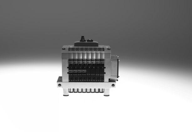
Valve terminals CPV, Compact Performance
|
|
|
- Angel Clementine Wilson
- 6 years ago
- Views:
Transcription
1

2 Key features Innovative Versatile Reliable Easy to mount Cubic design for exceptional performance and low weight Low installation and bus connection costs Ideal for decentralised machines and system structures, for example in handling technology in conveyor technology in the packaging industry in sorting systems in upstream machine functions Integrated diagnostics, condition monitoring (Fieldbus Direct) A string extension for Fieldbus Direct of 8 32 inputs and 8 32 outputs is possible without any difficulty (version-dependent) Flexible and cost-effective connection of 2 to 8 valve slices Highly flexible thanks to: various pneumatic functions (valve variants) different pressure ranges vacuum switches integrated vacuum generation relay plates with floating electrical outputs Separator plates for creating pressure zones Valves with integrated separation of ducts 1 and 11 Blanking plates for future expansion LED displays Manual overrides for valves Protection class to IP65 Protection class IP65 also in conjunction with pneumatic multiple connector plate for control cabinet assembly CE mark ATEX certification (see Technical Data) Ready-to-install and tested unit Lower selection, ordering, installation and commissioning costs Secure mounting on wall or H-rail Pneumatic multiple connector plate fast assembly without the need to replace the connected tubing Optimised assembly for control cabinets 2 Internet: Subject to change 2018/02
3 Key features CPV The benefits at a glance The CPV valve terminal has a unique design. It provides the flexible combination of pneumatic performance, electrical connection technologies and a wide range of mounting options. The pneumatic multiple connector plate supports space-saving installation in control cabinets. In many cases the valve terminal can be installed in the previously unused wall area of the control cabinet. There is no need to connect the valves in the control cabinet. All tube couplings can be laid externally. Instead of individual holes, the pneumatic multiple connector plate requires only one rectangular cutout. The generously sized flow ducts and powerful flat plate silencers ensure high flow rates. All valves are in the form of valve slices. They are optimised for flow performance and are also extremely compact. Two functions per valve slice (e.g. 2x 3/2-way valves) mean that twice the component density can be achieved. This saves space and reduces costs. The cubic design permits exceptional performance yet a comparatively low weight. The benefits of this design are obvious when the valve terminal is used on a drive in a moving installation. However, robustness must not be sacrificed in favour of compactness. The connecting threads and mounting attachments are metal. The manual override for the valves can be adapted for different operating situations. If, for example, a detenting manual override is required for setting-up mode, the manual override can be easily converted for that application in a way that rules out operational errors. The clear, large labelling system also contributes to the safe operation of the valve terminal. A particular plus is the range of electrical connection technologies supported. All types of valve actuation are possible, from individual valve connections up to bus systems with versatile expansion options. The integration of electrical input and output modules permits cost-effective solutions within the different installation concepts. The design principle The cubic design provides a clearly assigned function on each side. Thus, for example, the electrical connection is mounted on the top. An optional inscription label holder can be placed on the front of the valve terminal. The different combination options ensure the optimum solution for the task at hand. Compressed air supply connections on the left, right or underneath Pneumatic working lines and function blocks (vertical stacking) underneath Manual operation/identification on the front Electrical connection surface on the top Mounting surface at the back or the front via a pneumatic multiple connector plate 2018/02 Subject to change Internet: 3
4 Key features Main features Simple electrical connections: Individual connection/et200x/et200pro Multi-pin plug AS-interface I-Port interface/io-link Installation system CP/CPI Fieldbus Direct Operating voltage connection Quick mounting: Directly using screws On an H-rail Via the pneumatic multiple connector plate Robust metal thread or pre-assembled QS connectors Inscription labels Reduced downtimes: On-the-spot diagnostics via LEDs Reliable operation: Manual override, non-detenting, detenting or blocked Comprehensive range of valve functions, pressure zone creation, blanking plates Width 10 mm 14 mm 18 mm Equipment options Valve functions 5/2-way valve, single solenoid 5/2-way valve (with duct separation 1, 11), single solenoid 5/2-way valve, single solenoid, fast-switching 5/2-way valve, double solenoid 5/2-way valve (with duct separation 1, 11), double-solenoid 2x 3/2-way valve, normally closed 2x 3/2-way valve (with duct separation 1, 11), normally closed 2x 3/2-way valve, normally open 2x 3/2-way valve (with duct separation 1, 11), normally open 2x 3/2-way valve, 1x normally open, 1x closed 2x 3/2-way valve, (with duct separation 1, 11) 1x normally open, 1x closed 2x 3/2-way valve, normally closed, integrated back pressure protection 5/3-way valve, mid-position closed 2x 2/2-way valve, normally closed 2x 2/2-way valve (with duct separation 1, 11), normally closed 2x 2/2-way valve, 1x normally open, 1x closed 2x 2/2-way valve, (with duct separation 1, 11) 1x normally open, 1x closed Vacuum generator Vacuum generator and 2/2-way valve with ejector pulse On some terminals a relay plate with two floating contacts can be chosen instead of a valve sub-base Special features Individual connection Electrical connection for ET200X/ET200pro Multi-pin plug connection 2 8 valve positions, max. 16 solenoid coils 8 valve positions, max. 16 solenoid coils 4, 6 or 8 valve positions, max. 16 solenoid coils -H- Note A moulded seal is required for the valve terminal CPV10-ET200pro in order to achieve the IP protection class. The moulded seal CPV10- -GE-8 or CPV14- -GE-8 must be ordered separately. AS-interface I-Port interface/io-link Installation system CP/CPI Fieldbus Direct 2, 4 or 8 valve positions, max. 8 solenoid coils 4 or 8 inputs for 4 or 8 valve positions 8 valve positions, max. 16 solenoid coils Direct connection to the CTEU/CTEL installation system from Festo (I-Port) Connection to an IO-Link master 4, 6 or 8 valve positions, max. 16 solenoid coils CP/CPI string extension enables further valve terminals and I/O modules with CP/CPI function to be connected 8 valve positions, max. 16 solenoid coils CP/CPI string extension enables further valve terminals and I/O modules with CP/CPI functions to be connected 4 Internet: Subject to change 2018/02
5 Key features Electrical connections Individual connection (valve manifold) Connection is independent of the control technology used and is flexible thanks to pre-assembled cables. This ensures correct polarity during installation. The connector plug is equipped with an LED that indicates switching status, and an overvoltage protective circuit. It also features a built-in current reduction circuit. Individual connection permits the selection of 2 to 16 solenoid coils (divided between 2 to 8 valve slices, odd numbers also possible). An intrinsically safe version rounds off the range. Additional information Internet: cpv10-ex-vi ET200X/ET200pro pneumatic interface for CPV10 and CPV14 Adaptation of the CPV valve manifold to the input/output module ET200X/ET200pro from Siemens: the combination of the functional module of the ET200X/ET200pro and the pneumatic functions of the CPV valve manifold provides a highly integratable automation solution for systems using electrical and pneumatic drives with: 8 valve slices for up to 16 CPV valves Fast and secure contacting to IP65 CPV10 and CPV14 valve manifold Not permitted for CPV10-EX-VI High IP65/IP67 protection Modular design Multi-pin plug connection Control signals from the controller to the valve terminal are transmitted via a pre-assembled multi-wire cable, which substantially reduces installation time. The current reduction circuit for the valves is also integrated in the multi-pin plug connection. This valve terminal can be equipped with 4 to 16 solenoid coils (4, 6 or 8 valve slices). AS-interface connection A special feature of the AS-interface is the simultaneous transmission of data and supply power via a two-wire cable. The encoded cable profile prevents connection with incorrect polarity. If the valves have to be disconnected from mains power in an emergency, they can also be supplied with electrical power via a separate connection. Two versions are available for valve terminals for A/B operation. The valve terminal with AS-interface is available in the following versions: Without inputs, with two or four valve slices (max. 4 solenoid coils) and additional power supply With four inputs and four valve slices (max. 8 solenoid coils) With four or eight inputs and four or eight valve slices (max. 8 solenoid coils) and additional power supply With four or eight inputs and four or eight valve modules incl. vacant position or vacant positions and additional power supply (max. 6 solenoid coils for A/B mode in accordance with SPEC.2.1, max. 8 solenoid coils for A/B mode in accordance with SPEC. 3.0 with Profile 7.A.7) Additional information Internet: as-interface -H- Note Valve terminals to SPEC.2.1 cannot be operated on a master to SPEC.3.0 with profile 7.A /02 Subject to change Internet: 5
6 Valve terminal CPV, Compact Performance Selection and development Electrical connections I-Port interface/io-link, CTEL installation system A CTEL system consists of the CTEL master and the devices with I-Port interface, which are connected together using special connecting cables. This permits a decentralised layout of the devices. This means that the valve terminals and I/O modules with I-Port interface (devices) can be mounted very close to the cylinders to be controlled. This reduces the length of the air supply lines used, which minimises flow losses and pressurisation and venting times. The I-Port interface from Festo is based on IO-Link and is compatible with IO-Link in certain areas. The connection type corresponds to a star topology. In other words, only one module or valve terminal can be connected to each I-Port. As well as communication, the I-Port interfaces also handle the power supply for the connected devices. The maximum length of a string is 20 m. The restrictions compared to IO-Link include: Permanently set baud rate of kbps SIO mode is not supported Max. 32 bytes of input data and 32 bytes of output data Only one dump of the master commands is used "Festo plug & work" principle, configuration via IODD is not supported. More information Internet: cteu Internet: cpx Internet: cecc I-Port interface/io-link, CTEU system CTEU is a system for compact connection of a valve terminal to different fieldbus standards such as Profibus and DeviceNet. The fieldbus node is mounted directly on the I-Port interface of the valve terminal. This makes it easier to switch between the fieldbus protocols than with Fieldbus Direct, however there is no way of connecting I/O modules to the fieldbus nodes (as with the CPI string extension). The following fieldbus protocols are supported: DeviceNet Profibus DP CANopen CC-Link EtherCAT More information Internet: cteu 6 Internet: Subject to change 2018/02
7 Key features Electrical connections Installation system CP/CPI Valve terminals with CP connection are intended for connection to higherorder bus nodes or to control blocks. A bus node or control block also enables the connection of decentralised input/output units. The following bus protocols are supported: PROFIBUS DP INTERBUS DeviceNet CANopen CC-Link EtherNet/IP PROFINET POWERLINK EtherCAT Sercos III Four strings with up to 32 inputs and 32 outputs (version-dependent) can be connected to a bus node or control block. The CPV valve terminal is treated like an output module with up to 8 outputs (4, 6 or 8 valve slices or 4 to 16 solenoid coils per terminal). The connecting cables transmit all required electrical signals (control signals, operating voltage for the internal electronics of the modules and load voltage supply for connected valves). Additional information Internet: ctec Fieldbus Direct Fieldbus Fieldbus Direct is a system for the compact connection of a CPV or CPV-SC valve terminal to different fieldbus standards such as PROFIBUS and DeviceNet. The fieldbus node is directly integrated in the electrical interface of the valve terminal and therefore takes up only a minimal amount of space. The CPI string extension option allows the functions and components of the CPI system to be used. The new high-performance CPI string extension offers up to 4 supplementary CPI modules, combined with CP or CPI-compatible valve terminals for extension purposes. The Fieldbus Direct system can be expanded by 8 32 inputs and 8 32 outputs without any difficulty. 2018/02 Subject to change Internet: 7

8 Selection and development Valve terminal configurator The appropriate valve terminal can be chosen quickly and easily using the online catalogue. This includes an easy-to-use valve terminal configurator, which makes it much easier to find the right product. The valve terminals are fully assembled according to your order specification and are individually tested. This reduces assembly and installation time to a minimum. You order a valve terminal CPV using the order code. Ordering system for CPV Internet: cpv Online via: 2D/3D CAD data You can request the CAD data for a valve terminal you have configured. To do so, perform the product search as described above. Go to the shopping basket and click on the CAD icon (compass). On the next page you can generate a 3D preview or request another data format of your choice by . Online via: 8 Internet: Subject to change 2018/02
9 Peripherals overview Overview CPV valve terminal 1 ac ab aa aj Basic electrical unit (Fieldbus Direct, CP/CPI installation system, I-Port interface/io-link, AS-interface, multi-pin plug, individual connection) 2 Right-hand end plate with flat plate silencer 3 Comprehensive range of valve functions 4 Right-hand end plate (threaded connections not in conjunction with pneumatic multiple connector plate) 5 Holder for inscription label 6 QS push-in connectors 7 Function block (vertical stacking) 8 Pneumatic multiple connector plate 9 Left-hand end plate (threaded connections not in conjunction with pneumatic multiple connector plate) aj Left-hand end plate with flat plate silencer aa H-rail mounting ab Wall mounting ac Connecting cable for individual connection 2018/02 Subject to change Internet: 9
10 Key features Pneumatic components Valves CPV valves are valves with integrated sub-base, i.e. in addition to the valve function they contain all of the pneumatic ducts for supply, exhaust and the working lines. The supply ducts are a central component of the valve slices and allow a direct flow of air through the valve slices. This helps achieve maximum flow rates. All valves have a pneumatic pilot control for optimising performance. The valve function is based on a piston spool system with a patented sealing principle that guarantees its suitability for a wide range of applications as well as a long service life. The pneumatic components and functions are always identical for all actuator types. Most functions are also available in the various valve sizes (grid dimensions). Restrictions are noted where applicable. Valve function Code Circuit symbol Size Description M, MK 5/2-way valve, single solenoid Pneumatic spring return Piston spool valve With duct separation 1, 11 for valve MK Size 18 only available for valve M F J, JK C, CK CY 5/2-way valve, single solenoid Pneumatic spring return Piston spool valve Fast switching 5/2-way valve, double solenoid Piston spool valve With duct separation 1, 11 for valve JK Size 18 only available for valve J 2x 3/2-way valve, single solenoid Normally closed Pneumatic spring return Piston spool valve With duct separation 1, 11 for valve CK Size 18 only available for valve C 2x 3/2-way valve, single solenoid Normally closed Pneumatic spring return Integrated back pressure protection Piston spool valve Not suitable for vacuum -H- Note The valve terminal must be operated with external pilot air supply if it is necessary to ensure that the back pressure flaps are closed securely in the event of a sudden drop in operating pressure or if the operating pressure is switched off. 10 Internet: Subject to change 2018/02
11 Key features Pneumatic components Valve function Code Circuit symbol Size Description N, NK H, HK G 2x 3/2-way valve, single solenoid Normally open Pneumatic spring return Piston spool valve With duct separation 1, 11 for valve NK Size 18 only available for valve N The function of a 5/3-way valve with mid-position pressurised can be implemented with these valves with initial position open. 2x 3/2-way valve, single solenoid Normal position 1x open (pilot control 12) 1x closed (pilot control 14) Pneumatic spring return Piston spool valve With duct separation 1, 11 for valve HK Size 18 only available for valve H For optimised cylinder movement. Corresponds to valve function M with simultaneous actuation of both solenoid coils (5/2-way, single solenoid). Since the piston area on each side can be pressurised or exhausted separately, it means that the cylinder can move faster. 5/3-way valve, mid-position closed Mechanical spring return Piston spool valve 5/3G 1) function, mid-position closed For size 10 and 14 The valve function mid-position closed is created from one 2x 3/2-way valve, normally closed (code C). The valve kit CPV10-BS-5/3G-M7 or CPV14-BS-5/3G-1/8 (incorporating a double piloted non-return valve function) is used for this. This valve kit is intended for applications with one working pressure level per valve slice, i.e. it must not be used in dual-pressure applications (where the pressure levels at port 1 and 11 are different). If other valve slices are to be used in dual-pressure mode, then the valve slice equipped with the 5/3G valve kit must be separated from compressed air duct 1 and 11 by means of a separator plate (code T). Not in first or last valve position with pneumatic multiple connector plate P and M. Cannot be used with pneumatic multiple connector plate GQC and GQD. Piston spool valve 1) Cannot be assembled in conjunction with the control cabinet version of the pneumatic multiple connector plate CPV10-VI-P...-C or CPV10-VI-P...-D -H- Note A filter must be installed upstream of valves operated in vacuum mode. This prevents any foreign matter in the intake air getting into the valve (e.g. when operating a suction cup). 2018/02 Subject to change Internet: 11
12 Key features Pneumatic components Valve function Code Circuit symbol Size Description /3E function, mid-position exhausted The valve function mid-position exhausted is created using a 2x 3/2-way valve, normally closed (code C, CK). Pneumatic spring return Piston spool valve 5/3B function, mid-position pressurised The valve function mid-position pressurised is created using a 2x 3/2-way valve, normally open (code N, NK). Pneumatic spring return Piston spool valve D, DK 2x 2/2-way valve, single solenoid Normally closed Pneumatic spring return Piston spool valve With duct separation 1, 11 for valve DK Size 18 only available for valve D 2x 2/2-way valve, single solenoid Normal position 1x open (control side 12) 1x closed (control side 14) Pneumatic spring return Piston spool valve With duct separation 1, 11 for valve IK Size 18 only available for valve I A relay plate (code R) with (N/O contacts) can also be used instead of a valve slice. Each relay plate has two relays for actuating two electrically isolated outputs. Load capacity: 24 V DC, 1 A. Connecting cable KRP An inscription label holder cannot be used I, IK R Relay plate (2 floating contacts) 12 Internet: Subject to change 2018/02
13 Key features Pneumatic components Additional pneumatic functions Code Circuit symbol Size Description A E P Q V Vacuum generator Vacuum generator with ejector pulse Input (valve side) Output (cylinder side) Input (valve side) Output (cylinder side) Input (valve side) Output (cylinder side) Vacuum generation according to the ejector principle. Vacuum slices of different widths for different suction capacities. Combinations with a number of vacuum slices and/or directional control function slices are possible on the same valve terminal. In principle, an open connection is formed between the exhaust duct 3/5 and the working line 4. When the nozzle is not switched, the resulting back pressure in the exhaust duct flows back into the working line. When the nozzle is switched, the vacuum can be greatly reduced by the resulting back pressure. This effect is improved through optimised exhausting. It does not occur where there is only one vacuum generator per valve terminal and where separator plates (code S) are used for separation. Vacuum generator on pilot side 14 Reset via mechanical spring and pneumatic spring Ejector pulse on pilot side 12 (code E) Note air supply and exhaust when using more than two vacuum generators 2x one-way flow control valve, supply air flow control Module (actuator) for direct flange mounting on the CPV valves. Also suitable for pneumatic multiple connector plates. Different valve actuators cannot be combined. Not with valve function G Not in first or last valve position with accessories M, P, V (pneumatic multiple connector plate) Cannot be used with accessories GQC and GQD (pneumatic multiple connector plate) 2x one-way flow control valve, exhaust air flow control Module (actuator) for direct flange mounting on the CPV valves. Also suitable for pneumatic multiple connector plates. Different valve actuators cannot be combined. Not with valve function G Not in first or last valve position with accessories M, P, V (pneumatic multiple connector plate) Cannot be used with accessories GQC and GQD (pneumatic multiple connector plate) One-way flow control valve for vacuum The module CPV- -BS-GRZ-V- has a built-in non-return valve as well as a flow control function for adjusting the ejector pulse. The non-return valve serves to temporarily maintain the vacuum, even if the vacuum generator is switched off. The module is suitable for vacuum generators (code A, E). Not in first or last valve position with accessories M, P, V (pneumatic multiple connector plate) Cannot be used with accessories GQC and GQD (pneumatic multiple connector plate) 2018/02 Subject to change Internet: 13
14 Key features Pneumatic components Creating pressure zones Different pressures at port 1 and 11 result in two pressure levels per valve. This means, for example, that a cylinder drive can be advanced using high pressure and retracted using low pressure to save energy. The maximum number of pressure zones possible is determined by the combination of the following components: Use of a separator plate End plate pair type Valve slice type Number of valve slices The CPV valve terminal can be divided into 2 to 4 pressure zones with the aid of separator plates or valves with integrated duct separation. Separator plates/valves with integrated duct separation Code Graphical symbol Size Note T Separator plate for creating pressure zones, supply duct 1 and 11 separated Pilot exhaust air Pilot air supply Exhaust air Working air Working air 82/84 12/14 3/ A separator plate (code T) is used to separate the duct for the air supply (port 1 and 11) to provide two pressure zones. Not in first or last valve position Not with compressed air supply A, B, C, D, U, V, W, X S Separator plate for creating pressure zones, supply duct 1, 11 and exhaust 3/5 separated Pilot exhaust air Pilot air supply Exhaust air Working air 82/84 12/14 3/5 1 The separator plate (code S) separates the exhaust duct 3/5 as well as the supply duct 1 and 11. This plate should be used if one of the pressure zones is under vacuum to avoid any effects on the vacuum or to prevent back pressure on neighbouring valve functions. Not in first or last valve position Not with compressed air supply A, B, C, D, U, V, W, X (single-side compressed air supply) Working air 11 L Blanking plate (vacant position) A blanking plate (code L) is used to create a vacant position where a valve can be positioned at a later date. Pilot exhaust air 82/84 Pilot air supply Exhaust air 12/14 3/5 Working air 1 Working air 11 MK, JK, CK, NK, DK, IK Valve with integrated separation of ducts 1 and 11 Pilot exhaust air Pilot air supply Exhaust air 82/84 12/14 3/5 With these valves the ducts for the air supply (port 1 and 11) are closed to the right-hand side of the valve with a cast membrane. The advantage of using this instead of a separator plate is that no valve location is occupied by a separator plate. -H- Note Working air Working air 1 11 Where internal pilot air via the right-hand end plate is used as the compressed air supply, at least one further valve with the code M, F, J, C, CY, N, H, G, D, I, A or E must be used directly to the right of this valve. 14 Internet: Subject to change 2018/02
15 Key features Pneumatic components Examples: Compressed air supply External pilot air supply, flat plate silencer at both ends Compressed air supply via pneumatic multiple connector plate: code H The diagram opposite shows an example of the configuration and connection of the compressed air supply with external pilot air supply. Port 12/14 on the pneumatic multiple connector plate is equipped with a fitting for this purpose. Ports 3/5 and 82/84 are vented via the flat plate silencers. One separating seal each can be optionally used to create pressure zones. Optional separating seal Internal pilot air supply, ducted exhaust air or threaded silencer Compressed air supply via end plates: code Z The diagram opposite shows an example of the configuration and connection of the compressed air supply with internal pilot air supply. The pilot air is branched at the righthand end plate of port 1 or 11. Ports 3/5 and 82/84 are vented via the threaded silencer. One separating seal each can be optionally used to create pressure zones. Optional separating seal 2018/02 Subject to change Internet: 15
16 Key features Pneumatic components Example: Creating pressure zones CPV with separator plate T With the CPV valve terminals up to four pressure zones can be implemented. The diagram shows an example of the configuration and connection of four pressure zones using separator plate code T with external pilot air supply. Zone 2 Zone 1 Zone 4 Zone Vacuum 0.9 bar 2 Blast pulse 2 bar 3 Forward stroke 6 bar 4 Return stroke 4 bar CPV with integrated separation of ducts 1 and 11 with valves K With the CPV valve terminals up to four pressure zones can be implemented. The diagram shows an example of the configuration and connection of four pressure zones with external pilot air supply and the use of a valve K with integrated separation of ducts 1 and 11. Zone 2 Zone 1 Zone 4 Zone Vacuum 0.9 bar 2 Blast pulse 2 bar 3 Forward stroke 6 bar 4 Return stroke 4 bar 16 Internet: Subject to change 2018/02
17 Key features Pneumatic components Compressed air supply and exhausting The two end plates that pressurise and exhaust the valve slices are a characteristic feature of a CPV valve terminal: Large duct cross sections ensure maximum flow rates even when multiple valves are switched in parallel Large flat plate silencers in the end plates Internal/external pilot air supply Each individual valve is supplied with compressed air from two individual ducts (supply ports 1/11) and exhausted via a large, integrated exhaust duct (exhaust 3/5). This design permits unique flexibility and functionality. It is the easiest way of realising a number of pressure zones per terminal or combinations of vacuum applications. The valve terminal is supplied via end plates, either on the left, on the right or on both sides. End plate combinations other than those listed are possible (on request). Pilot air supply Internal pilot air supply Internal pilot air supply can be selected if the supply pressure at pneumatic port 1 is 3 8 bar. With internal pilot air supply the branch is located in the left or right-hand end plate. There is no port 12/14. External pilot air supply External pilot air supply is required if the supply pressure at pneumatic port 1 is less than 3 bar or greater than 8 bar. In this case, pressure of 3 8 bar is applied at port 12/14. If a gradual pressure build-up in the system using a pressurised on-off valve is required, external pilot supply air should be selected. The control pressure applied during switch-on is already very high in this case. External pilot air supply is also required if it is necessary to ensure that the back pressure flaps (valve order code CY) are closed securely in the event of a sudden drop in operating pressure or if the operating pressure is switched off. End plates Example of an end plate: The diagram shows a left-hand end plate with external pilot air supply. The exhaust ports 3/5 and 82/84 can be equipped with fittings or silencers. An end plate for internal pilot air supply does not have ports 12/14 and 11. The port 82/84 is always present and should be fitted with a silencer. The port 12/14 is connected internally with port 1 on an end plate for internal pilot air supply. 2018/02 Subject to change Internet: 17
18 Key features Pneumatic components End plate combination for compressed air supply via end plate Code Graphical symbol Type of pilot air supply (internal/external) Size Note U Internal pilot air supply 82/84 3/5 12/ Ports in right-hand end plate only No pressure zone separation permissible Not suitable for vacuum V Internal pilot air supply 82/84 3/5 12/ Ports in left-hand end plate only No pressure zone separation permissible Not suitable for vacuum W External pilot air supply 82/84 3/5 12/ Ports in right-hand end plate only No pressure zone separation permissible Suitable for vacuum X External pilot air supply 82/84 3/5 12/ Ports in left-hand end plate only No pressure zone separation permissible Suitable for vacuum Y Internal pilot air supply 82/84 3/5 12/ Ports in left-hand and right-hand end plate Maximum three pressure zones Valves to the left of the separator plate suitable for vacuum Z External pilot air supply 82/84 3/5 12/ Ports in left-hand and right-hand end plate Maximum four pressure zones Suitable for vacuum 18 Internet: Subject to change 2018/02
19 Key features Pneumatic components End plate combination for compressed air supply via pneumatic multiple connector plate Code Graphical symbol Type of pilot air supply (internal/external) Size Note Y Internal pilot air supply 82/84 3/5 12/ Ports on pneumatic multiple connector plate Pressure zone separation only permissible with separator plate (code T) Maximum two pressure zones Valves to the left of the separator plate suitable for vacuum Only for accessories M, P, V, GQC, GQD (pneumatic multiple connector plate) Z External pilot air supply 82/84 3/5 12/ Ports on pneumatic multiple connector plate Pressure zone separation only permissible with separator plate (code T) Maximum three pressure zones Suitable for vacuum Only for accessories M, P, V, GQC, GQD (pneumatic multiple connector plate) End plate combination for compressed air supply via end plates with flat plate silencer Code Graphical symbol Type of pilot air supply (internal/external) Size Note A Internal pilot air supply 82/84 3/5 12/ Ports in right-hand end plate No pressure zone separation permissible Not suitable for vacuum B Internal pilot air supply 82/84 3/5 12/ Ports in left-hand end plate No pressure zone separation permissible Not suitable for vacuum C External pilot air supply 82/84 3/5 12/ Ports in right-hand end plate No pressure zone separation permissible Suitable for vacuum D External pilot air supply 82/84 3/5 12/ Ports in left-hand end plate No pressure zone separation permissible Suitable for vacuum 2018/02 Subject to change Internet: 19
20 Key features Pneumatic components End plate combination for compressed air supply via pneumatic multiple connector plate with flat plate silencer Code Graphical symbol Size Type of pilot air supply (internal/external) Note E External pilot air supply 82/84 3/5 12/ Ports on pneumatic multiple connector plate Exhaust air vented via flat plate silencer on the right Pressure zone separation only permissible with separator plate (code T) Maximum four pressure zones Suitable for vacuum Only for accessories M, P, V, GQC, GQD (pneumatic multiple connector plate) Ports on pneumatic multiple connector plate Exhaust air vented via flat plate silencer on the left Pressure zone separation only permissible with separator plate (code T) Maximum four pressure zones Suitable for vacuum Only for accessories M, P, V, GQC, GQD (pneumatic multiple connector plate) Ports on pneumatic multiple connector plate Exhaust air vented via flat plate silencer on the left Pressure zone separation only permissible with separator plate (code T) Maximum three pressure zones Not suitable for vacuum Only for accessories M, P, V, GQC, GQD (pneumatic multiple connector plate) Ports on pneumatic multiple connector plate Exhaust air vented via flat plate silencers at both ends Pressure zone separation permissible Suitable for vacuum Only for accessories M, P, V, GQC, GQD (pneumatic multiple connector plate) F External pilot air supply 82/84 3/5 12/ G Internal pilot air supply 82/84 3/5 12/ H External pilot air supply 82/84 3/5 12/ J Internal pilot air supply 82/84 3/5 12/ Ports on pneumatic multiple connector plate Exhaust air vented via flat plate silencers at both ends Pressure zone separation permissible Maximum three pressure zones Valves to the left of the separator plate suitable for vacuum Only for accessories M, P, V, GQC, GQD (pneumatic multiple connector plate) Ports on pneumatic multiple connector plate Exhaust air vented via flat plate silencer on the right Pressure zone separation permissible Maximum three pressure zones Suitable for vacuum in combination with separator plate Only for accessories M, P, V, GQC, GQD (pneumatic multiple connector plate) K Internal pilot air supply 82/84 3/5 12/ Internet: Subject to change 2018/02
21 Key features Pneumatic components Pneumatic connection The working lines are located directly in the valve slices. Threaded connectors and Quick Star push-in fittings (QS) are available for different tubing sizes. The supply ports are located in the end plates or in the pneumatic multiple connector plate. Push-in fittings are available fully assembled. The following working lines can be selected: Large push-in connectors: code A Small push-in connectors: code B Threaded connectors: code C Connection sizes for the threaded and QS push-in fittings can be found in the table below. Pneumatic multiple connector plate One-piece connection plates that contain both working lines and supply ports can be combined with a pneumatic multiple connector plate. This enables the valve terminal as a pneumatic function to be separated from the valve ports. The pneumatic multiple connector plate enables different mounting options from wall mounting to direct passage through a cabinet wall. Easy-to-service and flexible connection technology thanks to the following: Common connection via the pneumatic multiple connector plate with all connections on one side The valve terminal can be assembled/disassembled using only four screws, whereby the pneumatics remain fully connected Quick assembly/disassembly No errors when recommissioning as a result of incorrect connection of tubing CPV valve terminal Pneumatic multiple connector plate /5 1 12/14 82/ Connection sizes Connection to ISO 5599 CPV10 CPV14 CPV18 Comment 1/11 Working air G1/8 G1/4 G3/8 Fitting in end plate or pneumatic multiple connector plate 2/4 Working line M7 (QS6/QS4) G1/8 (QS8/QS6) G1/4 (QS10/QS8) Connection in valve slice, connection for push-in fitting in brackets 3/5 Exhaust air port G3/8 G1/2 G1/2 Via right-hand/left-hand end plate G1/4 G3/8 G1/2 Pneumatic multiple connector plate 12/14 Pilot air supply port M5 G1/8 G1/4 Fitting in end plate or pneumatic multiple connector plate 82/84 Pilot exhaust air port M5 G1/8 G1/4 Via right-hand/left-hand end plate M7 (M5) 1) G1/8 G1/4 Pneumatic multiple connector plate 1) With flanged pneumatic multiple connector plate 2018/02 Subject to change Internet: 21
22 Key features Pneumatic components Pneumatic connection: fitting set for compressed air supply Code for compressed air supply Port Designation Size 10 QS6 Type Size 14 QS8 Type Size 18 QS10 Type Without pneumatic multiple connector plate U, V 82/84 Silencer AMTE-M-LH-M5 U-1/8-B U-1/4-B 3/5 Silencer U-3/8-B U-1/2-B U-1/2-B 1 Push-in fitting QS-1/8-8-I QS-1/4-10-I QS-3/8-12-I W, X 82/84 Silencer AMTE-M-LH-M5 U-1/8-B U-1/4-B 3/5 Silencer U-3/8-B U-1/2-B U-1/2-B 1 Push-in fitting QS-1/8-8-I QS-1/4-10-I QS-3/8-12-I 12/14 Push-in fitting QSM-M5-6-I QS-1/8-8-I QS-1/4-10-I Y 82/84 on right Silencer AMTE-M-LH-M5 U-1/8-B U-1/4-B 82/84 on left Blanking plug B-M5 B-1/8 B-1/4 3/5 on right Silencer U-3/8-B U-1/2-B U-1/2-B 3/5 on left Blanking plug B-3/8 B-1/2 B-1/2 1/11 on left Push-in fitting QS-1/8-8-I QS-1/4-10-I QS-3/8-12-I Z 82/84 on right Silencer AMTE-M-LH-M5 U-1/8-B U-1/4-B 82/84 on left Blanking plug B-M5 B-1/8 B-1/4 3/5 on right Silencer U-3/8-B U-1/2-B U-1/2-B 3/5 on left Blanking plug B-3/8 B-1/2 B-1/2 12/14 on right Push-in fitting QSM-M5-6-I QS-1/8-8-I QS-1/4-10-I 12/14 on left Blanking plug B-M5 B-1/8 B-1/4 1/11 Push-in fitting QS-1/8-8-I QS-1/4-10-I QS-3/8-12-I With pneumatic multiple connector plate; code M Y 82/84 Silencer UC-M7 U-1/8-B U-1/4-B 12/14 Blanking plug B-M7 B-1/8 B-1/4 3/5 Silencer U-1/4-B U-3/8-B U-1/2-B 1/11 on left Push-in fitting QS-1/8-8-I QS-1/4-10-I QS-3/8-12-I 11 on right Blanking plug B-1/8 B-1/4 B-3/8 Z 82/84 Silencer UC-M7 U-1/8-B U-1/4-B 3/5 Silencer U-1/4-B U-3/8-B U-1/2-B 12/14 Push-in fitting QSM-M7-6-I QS-1/8-8-I QS-1/4-10-I 1/11 on left Push-in fitting QS-1/8-8-I QS-1/4-10-I QS-3/8-12-I With pneumatic multiple connector plate; code P, GQC Y 82/84 Silencer AMTE-M-LH-M5 U-1/8-B U-1/4-B 12/14 Blanking plug B-M5 B-1/8 B-1/4 3/5 Silencer U-1/4-B U-3/8-B U-1/2-B 1/11 on left Push-in fitting QS-1/8-8-I QS-1/4-10-I QS-3/8-12-I 11 on right Blanking plug B-1/8 B-1/4 B-3/8 Z 82/84 Silencer AMTE-M-LH-M5 U-1/8-B U-1/4-B 3/5 Silencer U-1/4-B U-3/8-B U-1/2-B 12/14 Push-in fitting QSM-M5-6-I QS-1/8-8-I QS-1/4-10-I 1/11 on left Push-in fitting QS-1/8-8-I QS-1/4-10-I QS-3/8-12-I 22 Internet: Subject to change 2018/02
23 Key features Pneumatic components Pneumatic connection: fitting set for compressed air supply Code for compressed air supply Port Designation Size 10 QS6 Type Size 14 QS8 Type Size 18 QS10 Type Without pneumatic multiple connector plate A, B 82/84 Blanking plug B-M5 B-1/8 B-1/4 3/5 Blanking plug B-3/8 B-1/2 B-1/2 1 Push-in fitting QS-1/8-8-I QS-1/4-10-I QS-3/8-12-I C, D 82/84 Blanking plug B-M5 B-1/8 B-1/4 3/5 Blanking plug B-3/8 B-1/2 B-1/2 1 Push-in fitting QS-1/8-8-I QS-1/4-10-I QS-3/8-12-I 12/14 Push-in fitting QSM-M5-6-I QS-1/8-8-I QS-1/4-10-I With pneumatic multiple connector plate; code M E, F, H 82/84 Blanking plug B-M7 B-1/8 B-1/4 3/5 Blanking plug B-1/4 B-3/8 B-1/2 1/11 Push-in fitting QS-1/8-8-I QS-1/4-10-I QS-3/8-12-I 12/14 Push-in fitting QSM-M7-6-I QS-1/8-8-I QS-1/4-10-I G, J, K 82/84 Blanking plug B-M7 B-1/8 B-1/4 3/5 Blanking plug B-1/4 B-3/8 B-1/2 On right in 1, left Push-in fitting QS-1/8-8-I QS-1/4-10-I QS-3/8-12-I On right in 11 Blanking plug B-1/8 B-1/4 B-3/8 12/14 Blanking plug B-M7 B-1/8 B-1/4 With pneumatic multiple connector plate; code P, GQC E, F, H 82/84 Blanking plug B-M5 B-1/8 B-1/4 3/5 Blanking plug B-1/4 B-3/8 B-1/2 1/11 Push-in fitting QS-1/8-8-I QS-1/4-10-I QS-3/8-12-I 12/14 Push-in fitting QSM-M5-6-I QS-1/8-8-I QS-1/4-10-I G, J, K 82/84 Blanking plug B-M5 B-1/8 B-1/4 3/5 Blanking plug B-1/4 B-3/8 B-1/2 On right in 1, left Push-in fitting QS-1/8-8-I QS-1/4-10-I QS-3/8-12-I On right in 11 Blanking plug B-1/8 B-1/4 B-3/8 12/14 Blanking plug B-M5 B-1/8 B-1/4 2018/02 Subject to change Internet: 23
24 Key features Pneumatic components CPV valve terminal size 10 and 14 with valve extensions Function blocks CPV10-BS-5/3G-M7 CPV14-BS-5/3G-1/8 Valve kit 5/3G for creating a 5/3-way function, mid-position closed, for size 10 and 14: The valve function mid-position closed is created using one valve slice with 2x 3/2-way valve, normally closed (valve function code C). The valve kit CPV10-BS-5/3G-M7 or CPV14-BS-5/3G-1/8 (incorporating a double piloted non-return valve function) is used for this. This valve kit is intended for applications with one working pressure level per valve slice, i.e. it must not be used in dual-pressure applications (where the pressure levels at port 1 and 11 are different). Additional functions for valve positions These valve extensions (vertical stacking) can be used to add further pneumatic functions to CPV valve terminals size 10 and 14: Two one-way flow control valves for flow regulation directly at the valve terminal for supply air flow control exhaust air flow control The vacuum flow control module must be used with the vacuum generator with or without ejector pulse and provides a non-return function and adjustable ejector pulse -H- Note The additional functions cannot be used in the first or last valve position in combination with the pneumatic multiple connector plate M, P and cannot be used in combination with the pneumatic multiple connector plate GQC, GQD. CPV10-BS-2xGRZZ-M7 CPV14-BS-2xGRZZ-1/8 2x one-way flow control valve for supply air flow control Additional function code P CPV10-BS-2xGRAZ-M7 CPV14-BS-2xGRAZ-1/8 2x one-way flow control valve for exhaust air flow control Additional function code Q CPV10-BS-GRZ-V-M7 CPV14-BS-GRZ-V-1/8 Vacuum flow control module Additional function code V 24 Internet: Subject to change 2018/02
25 Key features Assembly Mounting options The valve terminals have holes for four mounting screws. The mounting side is the side with the pneumatic fittings. These holes are also used to mount the valve terminal on a pneumatic multiple connector plate. There are other mounting options in addition to this method: H-rail mounting Wall mounting Wall mounting via flanged pneumatic multiple connector plate On rear side via wall mounting On front side (CPV10/14 with IC connection only) Mounting via through-hole in wall The attachments are mounted with a screw and fixing bolt on the left-hand and right-hand end plates. Attachment for H-rail For valve terminal CPV10/14: CPV10/14-VI-BG-NRH-35 (mounting code H) For valve terminal CPV18: CPV18-VI-BG-NRH-35 (mounting code H) H-rail to EN 60715, not for accessories M, P, V (pneumatic multiple connector plate) Attachment for wall mounting For valve terminal CPV10/14: CPV10/14-VI-BG-RWL-B (mounting code U) For valve terminal CPV18: CPV18-VI-BG-RW (mounting code W) Attachment for individual connection and ET200X/ET200pro (included in the scope of delivery) For valve terminal CPV10/14: CPV -VI-BG-ET200X (mounting code X) Through-hole in wall, for example on the machine Wall mounting via pneumatic multiple connector plate 2018/02 Subject to change Internet: 25
26 Key features Assembly Pneumatic multiple connector plate for wall/machine mounting With flange, with all pneumatic connections, code P Without flange, with all pneumatic connections, code M 1 For 10 mm, 14 mm and 18 mm Multiple connector plate projects past the end plates Through mounting holes (without thread) in the flange Two additional holes running laterally through the pneumatic multiple connector plate also enable rear mounting of the CPV valve terminal 1 1 Mounting holes 1 Mounting holes 1 For 10 mm, 14 mm and 18 mm Multiple connector plate fits flush with the end plates Mounting holes (with thread) for wall or foot mounting are on the connection side of the pneumatic multiple connector plate Pneumatic multiple connector plate for control cabinet assembly With all pneumatic connections, code GQC With pneumatic ports 2 and 4, code GQD 1 For 10 mm and 14 mm Multiple connector plate projects past the end plates Mounting holes (with thread) in the flange Multiple connector plate with seal 1 For 10 mm and 14 mm Multiple connector plate fits flush with the end plates The mounting holes (with thread) are on the connection side of the pneumatic multiple connector plate Multiple connector plate with seal 1 Mounting holes 1 Mounting holes With all pneumatic connections, code GQE For 10 mm Multiple connector plate projects past the end plates Mounting holes (with thread) in the flange Multiple connector plate with seal 1 Mounting holes 1 -H- Note The outer valve slices cannot be equipped with valve extensions (e.g. one-way flow control valve) when using the pneumatic multiple connector plate M or P. CPV valve terminals with flat plate silencers are only suitable for wall mounting. If the pneumatic multiple connector plate GQC, GQD or QQE is used, the following limitations apply: Generally no attachment of valve extensions Not in combination with H-rail mounting Not in combination with wall mounting Only with 10 mm and 14 mm 26 Internet: Subject to change 2018/02
27 Key features Display and operation Manual override Three types of manual override are available: Non-detenting via slide Detenting Blocked Subsequent conversion of the manual override from non-detenting to detenting or blocked is possible at any time. The locking clip on the valve must be removed to this end. This is only possible after the individual valve has been removed or the tie rod of the valve terminal has been released. -H- Note See the manual for instructions. Code Graphical symbol Size Note N Manual override, non-detenting In the non-detenting version, the blue slide is held via a locking clip. A pointed object (e.g. pen, etc.) can be used to activate the manual override through the opening. R Manual override, detenting In the detenting version, the locking clip is removed and the manual override is activated by pushing the slide down. The non-detenting function can be re-established by re-installing the locking clip. V Manual override, blocked In the blocked version, non-detenting and detenting activation of the manual override is prevented by means of a cover. Like the non-detenting locking clip, this cover can be added subsequently, but then remains on the valve. 2018/02 Subject to change Internet: 27
28 Key features Display and operation Display and operation You will find the following LEDs for displaying the switching status on the electrical connections of the CPV valve terminal: Display of the switching status of the pilot solenoid coil 12 for outlet port 2 Display of the switching status of the pilot solenoid coil 14 for outlet port 4 Readable from the top as well as from the front The individual connection has an LED in the connector plug to display the switching status. Inscription labels Clip with inscription field on connection plug (with individual connection) Inscription clips on connection node (multi-pin plug, AS-interface, CP installation system, Fieldbus Direct) CPV valve manifold with individual connection CPV valve terminal with multi-pin plug connection Pre-assembled connecting cable for each pilot solenoid coil 2 Slot for inscription label 3 Yellow LED, signal status display for pilot solenoid coils (for each connecting cable) 4 Earth terminal 5 Terminal lugs for solenoid coil 14 6 Terminal lugs for solenoid coil 12 7 Sub-D multi-pin plug (9-pin for valve terminals with 4 valves, 25-pin for valve terminals with 6 or 8 valves) Identification system Inscription labels type IBS-6x10 for CPV10/14 type IBS 9x20 for CPV18 Transparent inscription label holder for paper labels (readable from both sides) Inscription label holder Inscription labels type IBS 6x10 Inscription labels can be affixed as follows: On the top of the electrical base unit On the inscription label holder The inscription label holder permits the addition of inscription labels, protects the manual overrides and prevents them from being accidentally activated. The inscription labels are used to record additional information regarding the valves. The inscription label holders can be ordered together with the valve terminal using the order code. The relevant inscription labels are supplied in a frame and are ordered separately. The inscription label holder cannot be used together with the relay plate. Transparent inscription label holder The transparent inscription label holder CPV -VI-ST- offers a further labelling option, for example for large paper labels that can be read from both sides. -H- Note The Word templates for CPV label holders can be found at: 28 Internet: Subject to change 2018/02
29 Key features Electrical components Electrical connection Contacts that are fitted on the top of the valve slices form the interface for various electrical connection options. The electrical connection is attached from above using four screws. This Electrical power means that the valve terminal can be adapted to different electrical requirements or fieldbus protocols using the same pneumatic part. I [ma] t [ms] CPV10/14 valves are actuated by means of an integrated current reduction circuit, which reduces power consumption and heat build-up. This current reduction circuit is integrated in the basic electrical unit (multi-pin plug or fieldbus connection) or in the connecting cable. During switch-off, the voltage peaks are limited to 38 V DC. Individual connection With an individual connection integration is only carried out in the pneumatic part, the solenoid valves are connected with individual cables. 2018/02 Subject to change Internet: 29
30 Key features Electrical components Dimensions Connecting cable for individual connection KMYZ KMEB LED Download CAD data 1 Mounting screw 2 Wire end sleeve 3 Cable, depending on order 1 LED illuminated area 2 Inscription label IBS-9x20 Part No wire cable 2.5 or 5 m (3x 0.75 mm 2 ) 4 Connection pattern to EN , type C 5 M2.5 screw, captive, threaded head: Z-combi cross-slot screws to EN 7045 Type B1 D1 H1 H2 L1 L2 L3 L5 NEBV-Z3WA2L KMEB ,5-LED KMEB LED 5000 Dimensions Connecting cable for relay plate KRP Download CAD data 2 Location for inscription labels (order code IBS 6x10, Part No ) 3 Cable, depending on order 5 Mounting screw (self-tapping KB 1.8x9) Type B1 D1 H1 H2 L2 L3 KRP Internet: Subject to change 2018/02
31 Key features Electrical components ET200X/ET200pro pneumatic interface for CPV10 and CPV14 Adaptation of the CPV valve manifold to the input/output module ET200X/ET200pro from Siemens. The combination of the functional modules of the ET200X/ET200pro and the pneumatic functions of the CPV valve manifold provides a highly integratable automation solution for systems using electrical and pneumatic drives with: 8 valve slices for up to 16 CPV valves Faster and more reliable contacting CPV 10 and CPV 14 valve manifold High IP65/IP67 protection Modular design Large number of I/O modules digital I/O analogue I/O supply branching for activation of three-phase motors Profibus DP interface Mounting kit for ET200X CPV- -VI-BG-ET200X (included in the scope of delivery) Specific data on the ET200X/ET200pro pneumatic interface can be found in Siemens product catalogues. -H- Note A moulded seal is required for the valve manifold CPV10-ET200pro in order to achieve the IP protection class. The moulded seal CPV10- -GE-8 or CPV14- -GE-8 must be ordered separately. 2018/02 Subject to change Internet: 31
32 Key features Electrical components Multi-pin plug connection In addition to pneumatic integration, a multi-pin plug connection also provides integration of the electrical side and facilitates connection to the control cabinet and the valve terminal via a single cable. Sub-D 9-pin and 25-pin plugs are used for connection. The plug housing of the KMP- - cable provides the Sub-D connectors with IP65 protection. The following sizes of plug connector are used: 4-valve valve terminal: 9-pin 6-valve valve terminal: 25-pin 8-valve valve terminal: 25-pin Prefabricated connecting cables are available for easy connection. Standard lengths of 5 m and 10 m can be supplied. The pre-assembled connecting cables are also available in a design suitable for use with energy chains. The cable KMP6- can alternatively be used for applications with IP40 protection. Pin allocation Pre-assembled multi-pin cable (viewed from plug-in direction) Plug view Pin Wire colour Valve 24 V DC Cable KMP3-25P-16 or KMP4-25P with 25-pin Sub-D plug for 6-valve and 8-valve valve terminal 1 White Green 12 3 Yellow Grey 12 5 Pink Blue 12 7 Red Purple 12 9 Grey-pink Red-blue White-green Brown-green White-yellow Yellow-brown White-grey Grey-brown White-pink (KMP4 only) 18 Pink-brown (KMP4 only) 19 White-blue (KMP4 only) 20 Brown-blue (KMP4 only) 21 White-red (KMP4 only) 22 Brown-red (KMP4 only) 23 White-black (KMP4 only) 24 Brown (0 V) 1) 25 Black (0 V) 1) Cable KMP3-9P or KMP4-9P with 9-pin Sub-D plug for 4-valve valve terminal 1 White Green 12 3 Yellow Grey 12 5 Pink Blue 12 7 Red Purple 12 9 Black Common 1) 0 V for positive switching control signals; connect 24 V for negative switching control signals; mixed operation is not permitted. 32 Internet: Subject to change 2018/02
33 Key features Electrical components Pin allocation Pre-assembled multi-pin cable (viewed from plug-in direction) Plug view Pin Wire colour Valve 24 V DC Cable KMP6-25P-20 with 25-pin Sub-D plug for 6-valve and 8-valve valve terminals 1 White Brown 12 3 Green Yellow 12 5 Grey Pink 12 7 Blue Red 12 9 Black Purple Grey-pink Red-blue White-green Brown-green White-yellow Yellow-brown White-grey 18 Grey-brown 19 White-pink 20 Pink-brown 21 White-blue 1) 22 Brown-blue 1) 23 White-red 1) 24 Brown-red 1) (0 V) 2) 25 White-black 1) (0 V) 2) Cable KMP6-9P-20 with 9-pin Sub-D plug for 4-valve valve terminals 1 White Brown 12 3 Green Yellow 12 5 Grey Pink 12 7 Blue Red 12 9 Black Common 1) Wire cross section 0.34 mm 2 2) 0 V for positive switching control signals; connect 24 V for negative switching control signals; mixed operation is not permitted. -H- Note Two threaded sleeves (NEAU-TA-M35-U4, p. 63) are required to secure the multi-pin cable MKP /02 Subject to change Internet: 33
34 Key features Electrical components Valve terminal CPV AS-interface valve terminal The AS-interface facilitates wide ranging physical distribution of individual components or small component groups. The AS-interface connection of valve terminal CPV can be used to control 2, 4, 8 solenoid coils. The valve terminal cover contains the LEDs that indicate the operating status and the protective circuit for the valves. The AS-interface protocol standard permits a maximum of 4 inputs and 4 outputs in one unit. The use of 2 ASinterface slaves in one valve terminal means that 8 inputs and 8 outputs can be controlled in an 8-valve valve terminal (8 solenoid coils). All CPV valve terminals can be operated using additional functions, e.g. relay plates or vacuum generators. Valve terminals CPV with inputs are also available for A/B operation to SPEC 2.1 and 3.0. AS-interface control For 2, 4 or 8 valves Great variety thanks to the wide range of modules in the system AS-interface with A/B operation For 3 or 4 and/or 6 or 8 valves depending on the specification All the benefits of the simple installation system are retained 100% more inputs/master 50% more outputs/master Improved peripheral error diagnostics More AS-interface functions in Specifications 2.1 and 3.0 Internet: as-interface AS-interface valve terminal with auxiliary power supply AS-interface valve terminal with auxiliary power supply and inputs 34 Internet: Subject to change 2018/02
35 Key features Electrical components I-Port interface/io-link The I-Port interface/io-link enables the valve terminal CPV to be connected to the following systems: I-Port master from Festo (CPX terminal, CECC) Fieldbus node CTEU from Festo IO-Link master A maximum of 16 solenoid coils can be actuated distributed over a maximum of 8 valve positions. The maximum distance between the I-Port/IO-Link master and valve terminal with I-Port interface/io-link is 20 m. The 5-pin connecting cables contain the power supply for the valves, separate from this is the power supply for the internal valve terminal electronics and the control signals. The valve terminal cover contains the LEDs that indicate the operating status and the protective circuit for the valves. All valve terminals CPV can be operated with other functions such as relay plates or vacuum generators. Internet: cteu Internet: cpx Internet: cecc CPV valve terminal with I-Port interface/io-link CPV valve terminal with I-Port interface with fieldbus node CP/CPI installation system, valve terminal The integration of valve terminal CPV into a fieldbus system or independent control system is accomplished by connecting the terminal to the corresponding fieldbus node or control block with simple, pre-assembled terminal connectors. The 5-pin connecting cables carry the supply power and control signals. The valve terminal cover contains the LEDs that indicate the operating status and the protective circuits for the valves. The CP string is used to exchange the input and output states of the connected modules with the CP fieldbus node. Internet: ctec The installation system integrates the valve terminal CPV and various I/O modules, etc. into a single installation concept. Max. 8 valve slices for up to 16 CPV valves /02 Subject to change Internet: 35
36 Instructions for use Fieldbus Direct valve terminal Fieldbus Direct is a system for connecting one valve terminal to nine different fieldbus standards. The most important systems, including PROFIBUS, INTERBUS, DeviceNet and CANopen, are supported. The CP string extension option enables the functions and components of the CPI installation system to be used. The optional string extension permits additional valve terminals and I/O modules with CP/CPI function to be connected to the Fieldbus Direct fieldbus node. Depending on the version, the valve terminals are available in all three sizes, 10, 14 and 18 mm, each with 8 valve slices. Equipment Operate system equipment with unlubricated compressed air if possible. Festo valves and cylinders are designed so that, if used as designated, they will not require additional lubrication and will still achieve a long service life. The quality of compressed air downstream of the compressor must correspond to that of unlubricated compressed air. If possible, do not operate all your system equipment with lubricated compressed air. The lubricators should, where possible, always be installed directly upstream of the actuator used. Incorrect additional oil and too high an oil content in the compressed air reduce the service life of the valve terminal. Use Festo special oil OFSW-32 or the alternatives listed in the Festo catalogue (as specified in DIN HLP32; basic oil viscosity 32 CST at 40 C). Bio-oils When using bio-oils (oils based on synthetic or native ester, e.g. rapeseed oil methyl ester), the maximum residual oil content of 0.1 mg/m 3 must not be exceeded (see ISO Class 2). Mineral oils When using mineral oils (e.g. HLP oils to DIN 51524, parts 1 to 3) or similar oils based on poly-alpha-olefins (PAO), the maximum residual oil content of 5 mg/m 3 must not be exceeded (see ISO Class 4). A higher residual oil content irrespective of the compressor oil cannot be permitted, as the basic lubricant would be flushed out over time. 36 Internet: Subject to change 2018/02
 Type of mounting Via pneumatic multiple")
37 Technical data -M- Flow rate up to CPV10: 400 l/min CPV14: 800 l/min CPV18: 1600 l/min -K- Valve width CPV10: 10 mm CPV14: 14 mm CPV18: 18 mm -P- Voltage 24 V DC General technical data CPV10 CPV14 CPV18 Design Electromagnetically actuated piston spool valve Lubrication Life-time lubrication, PWIS-free (free of paint-wetting impairment substances) Type of mounting Via pneumatic multiple connector plate Via backwall On H-rail Mounting position Any Manual override Non-detenting/detenting/blocked Width [mm] Nominal size [mm] Nominal flow rate without fitting [l/min] ) b value ) ) ) c value [l/sbar] ) Pneumatic connections 1) Pneumatic connection Via end plate or pneumatic multiple connector plate Supply port 1/11 G1/8 G1/4 G3/8 Exhaust port 3/5 G3/8 (G1/4) G1/2 (G3/8) G1/2 Working ports 2/4 M7 G1/8 G1/4 Pilot air supply port 12/14 M5 (M7) G1/4 G1/4 Pilot exhaust air port 82/84 M5 (M7) G1/8 G1/4 1) Connection dimensions in brackets for pneumatic multiple connector plate 2) Values for 2x 2/2-way valve 3) Values for 5/3-way valve with mechanical spring return Safety characteristics CPV10 CPV14 CPV18 Max. positive test pulse with 0 signal [ìs] Max. negative test pulse with 1 signal [ìs] Shock resistance Shock test with severity level 2, to EN Vibration resistance Transport application test with severity level 2, to EN /02 Subject to change Internet: 37
Valve manifold CPV10-EX-VI, Compact Performance
 Key features Innovative Versatile Reliable Easy to mount Cubic design for exceptional performance and low weight Sturdy Optimised for installation in a control cabinet Suitable for pilot control of process
Valve terminals CPV-SC, Smart Cubic
 Key features Innovative Versatile Reliable Easy to mount Small, compact valve terminal for a wide range of pneumatic applications Enormous flexibility during planning, assembly and operational use Multi-pin
Valve terminals MPA-L
 Key features Innovative Versatile Reliable Easy to assemble Compact, high-performance valves in a sturdy metal housing Flow rates up to 870 l/min Wide range of electrical connection options for multi-pin
Valve Manifolds Type 44 VTSA, Type 45 VTSA-F Metric Series Overview
 Overview Modular multi-functional valve manifold for up to 3 valves: Type 44 VTSA, ISO 15407-/ISO 5599- Type 45 VTSA-F with optimized flow Different valve sizes on one valve manifold: 18 mm (ISO 0) 6 mm
Valve Manifolds Type 44 VTSA, Type 45 VTSA-F Inch Series Overview
 Overview Modular multi-functional valve manifold for up to 3 valves: Type 44 VTSA, ISO 15407-/ISO 5599- Type 45 VTSA-F with optimized flow Different valve sizes on one valve manifold: 0.71 in (ISO 0) 1.0
Valve terminals MPA-F
 Key features Innovative Versatile Reliable Easy to mount Manifold blocks, tubing connections and exhausts designed for optimum flow rates Tubing diameters: Working ports up to 10 mm Supply ports up to
Pneumatic valves VUWS/valve manifold VTUS
 Pneumatic valves VUWS/valve manifold VTUS -V- New VUWS-LT25, VTUS-25 Pneumatic valves VUWS/valve manifold VTUS Key features Innovative Versatile Reliable Easy to install A reliable, heavy-duty valve with
Valve terminals MPA-L
 Key features Innovative Versatile Reliable Easy to assemble Compact, high-performance valves in a sturdy metal housing Flow rates up to 870 l/min Wide range of electrical connection options for multi-pin
Pneumatic valves VUWS/valve manifold VTUS
 Pneumatic valves VUWS/valve manifold VTUS -V- New VUWS-LT25, VTUS-25 Pneumatic valves VUWS/valve manifold VTUS Key features Innovative Versatile Reliable Easy to install A reliable, heavy-duty valve with
Solenoid valves VUVS/valve manifold VTUS, NPT
 Solenoid valves VUVS/valve manifold VTUS, NPT Solenoid valves VUVS/valve manifold VTUS, NPT Key features Innovative Versatile Reliable Easy to install A reliable, heavy-duty valve with a long service life
Valve terminal CPA, Compact Performance
 Key features Innovative Flexible Reliable Easy to assemble Compact valves in sturdy metal housing Patented electrical linking system for flexible expansion options Standardised system of electrical connection
Valve terminals VTSA/VTSA-F, NPT
 Key features Innovative Versatile Reliable Easy to install High-performance valves in sturdy metal housing Four valve sizes on one valve terminal Standardised from the multi-pin plug to the fieldbus connection
Multi-talented. Valve and valve terminal series VG
 Valve and valve terminal series VG Multi-talented. Highlights VUVG Compact with high flow rate Can be used as an individual valve or mounted on a valve manifold. 2x 3/2 one valve body, two functions Simple
Compact Performance CPV valve terminal Pneumatics
 Compact Performance CPV valve terminal Pneumatics Typ: CPV..-VI Author: Editors: Translation: Layout: M. Simons H.-J. Drung, M. Holder Douglas Smith Festo, Dept. KI-TD Edition: 9811d Printed on 100 %
Multitalented. Valve and valve terminal series VG. Compact and high flow rates!
 Valve and valve terminal series VG Compact and high flow rates! Multitalented. Highlights VUVG Compact and with high flow rates Can be expanded into a valve terminal with an individual connection 2x 3/2-way
Solenoid valves VMPA
 Key features Innovative Versatile Reliable Easy to mount Slim high-performance valves in a sturdy metal housing MPA1 (width 10 mm): flow rate up to 360 l/min MPA14 (width 14 mm): flow rate up to 670 l/min
Solenoid valves VUVS/valve manifold VTUS, NPT
 Solenoid valves VUVS/valve manifold VTUS, NPT -V- New VUVS-LT25, VTUS-25 Solenoid valves VUVS/valve manifold VTUS, NPT Key features Innovative Versatile Reliable Easy to install A reliable, heavy-duty
Compact performance. Manual CPV pneumatics Individual valve connection. CPV valve terminal Type CPV10-EX-VI. Manual en 1203d [762328]
![Compact performance. Manual CPV pneumatics Individual valve connection. CPV valve terminal Type CPV10-EX-VI. Manual en 1203d [762328]](/thumbs/79/78926204.jpg "Compact performance. Manual CPV pneumatics Individual valve connection. CPV valve terminal Type CPV10-EX-VI. Manual en 1203d [762328]") Compact performance 712689 Manual CPV pneumatics Individual valve connection CPV valve terminal Type CPV10-EX-VI Manual 547040 en 1203d [762328] Contents and general instructions Original... de Edition...
Compact performance 712689 Manual CPV pneumatics Individual valve connection CPV valve terminal Type CPV10-EX-VI Manual 547040 en 1203d [762328] Contents and general instructions Original... de Edition...
Valve terminals VTSA/VTSA-F
 Key features Innovative Versatile Reliable Easy to mount High-performance valves in sturdy metal housing Four valve sizes on one valve terminal Standardised from the multi-pin plug to the fieldbus connection
Valve terminal CPA, Compact Performance
 Valve terminal CPA, Compact Performance Key features Innovative Flexible Reliable Easy to assemble Compact valves in sturdy metal housing Patented electrical linking system for flexible expansion options
Valve terminals MPA-S
 Key features Innovative Versatile Reliable Easy to mount Slim high-performance valves in sturdy metal housing MPA1 flow rates up to 360 l/min MPA2 flow rates up to 700 l/min From the individual valve to
Compact performance. Pneumatics Manual CPV. CPV valve terminal Type CPV...-VI. Manual en 0005e
 Compact performance Pneumatics Manual CPV CPV valve terminal Type CPV...-VI Manual 165 200 en 0005e Contents and general instructions Author... M. Simons Editors... H.-J. Drung, M.Holder Original... de
Valve terminals MPA-S
 Key features Innovative Versatile Reliable Easy to mount Slim high-performance valves in sturdy metal housing MPA1 flow rates up to 360 l/min MPA2 flow rates up to 700 l/min From the individual valve to
Compact performance. Manual CPV pneumatics. CPV valve terminal Type CPV...-VI. Manual en 1609i [ ]
![Compact performance. Manual CPV pneumatics. CPV valve terminal Type CPV...-VI. Manual en 1609i [ ]](/thumbs/74/71326626.jpg "Compact performance. Manual CPV pneumatics. CPV valve terminal Type CPV...-VI. Manual en 1609i [ ]") Compact performance Manual CPV pneumatics CPV valve terminal Type CPV...-VI Manual 165200 en 1609i [8064940] Contents and general instructions Original... de Edition... en 1609i Designation... P.BE-CPV-EN
Compact performance Manual CPV pneumatics CPV valve terminal Type CPV...-VI Manual 165200 en 1609i [8064940] Contents and general instructions Original... de Edition... en 1609i Designation... P.BE-CPV-EN
Solenoid valves MH2/MH3/MH4, fast-switching valves
 Solenoid valves MH2/MH3/MH4, fast-switching valves Fast-switching valves from Festo: it's not just the switching that's fast The fast-switching professionals with response times down to 2 milliseconds
Valve terminal VTUG-...-M/VTUG-...-V
 Valve terminal VTUG-...-M/VTUG-...-V 2 Design 2. Standard valve terminal (straight connecting plate) 2 3 4 Festo AG & Co. KG Ruiter Straße 82 73734 Esslingen Germany +49 7 347-0 www.festo.com Brief description
A quick match. Your selection tool for choosing valves and valve terminals.
 A quick match Your selection tool for choosing valves and valve terminals. The valve series at a glance: From individual valves... Simple, cost-effective, expandable CPV VTUG with plug-in VUVS VUVG Valve
Solenoid valves MH2/MH3/MH4, fast-switching valves
 Solenoid valves MH2/MH3/MH4, fast-switching valves Fast-switching valves from Festo: it's not just the switching that's fast The fast-switching professionals with response times down to 2 milliseconds
Control block VOFA with safety function
 Key features Innovative Versatile Reliable Easy to assemble Can be used for safe reversing of a hazardous movement (5/2-way solenoid valve) Can be used for safe venting (3/2-way solenoid valve function,
The better alternative!
 The new standard: valve range VUVG The better alternative! Highlights Extremely long service life Smallest possible dimensions Very quick and easy installation Easy ordering Pressure range -0.9 to 10 bar
Solenoid/pneumatic valves, ISO
 Solenoid/pneumatic valves, ISO 15407-1 q/w Worldwide: Superb: Easy: Festo core product range Covers 80% of your automation tasks Always in stock Festo quality at an attractive price Reduces procurement
Solenoid valves VUVB/valve terminals VTUB, NPT
 Solenoid valves VUVB/valve terminals VTUB, NPT Solenoid valves VUVB/valve terminals VTUB, NPT Key features Innovative Versatile Reliable Easy to mount Valve terminal for a wide range of pneumatic applications
Valve terminals VTUB-12
 Key features Innovative Versatile Reliable Easy to mount Cost-effective I-Port interface for fieldbus nodes (CTEU) IO-Link mode for direct connection to a higher-level IO-Link master Lower installation
FAST Program 2010 Festo Assured Shipping Time
 FAST Program 010 Festo Assured Shipping Time A complete line of automation components available when you need them! FAST Program 010 Festo Assured Shipping Time A complete line of automation components
V New VSVA. Solenoid/pneumatic valves, ISO Electrically or pneumatically actuated valves. With internal or external pilot air
 V New VSVA B01_01_001_E Solenoid/pneumatic valves, ISO 15 407 1 Electrically or pneumatically actuated valves With internal or external pilot air Pneumatic or mechanical reset Ausgewählte Typen nach ATEX
Motion Terminal VTEM. Festo core product range Covers 80% of your automation tasks
 q/w Worldwide: Superb: Easy: Festo core product range Covers 80% of your automation tasks Always in stock Festo quality at an attractive price Reduces procurement and storing complexity qgenerally ready
Solenoid valves VUVG/valve terminals VTUG
 Solenoid valves VUVG/valve terminals VTUG q/w Worldwide: Superb: Easy: Festo core product range Covers 80% of your automation tasks Always in stock Festo quality at an attractive price Reduces procurement
Valve terminals type 03 VIMP-/VIFB-03, multi-functional MIDI/MAXI
 Key features Innovative Versatile Reliable Easy to mount Multi-functional valve terminal in sturdy metal housing Electrical interlinking module for flexible expansion options Standardised system of electrical
Solenoid valves VOVG Product range overview
 Valve series VOVG Product range overview Function Symbol Version Normally Voltage [V DC] Page/ open closed 5 12 2 Internet /2-way valve In-line valve 8/vovg Semi in-line valve Sub-base valve 5/2-way valve
Solenoid valves VUVB/valve terminals VTUB
 Solenoid valves VUVB/valve terminals VTUB Solenoid valves VUVB/valve terminals VTUB Key features Innovative Versatile Reliable Easy to mount Valve terminal for a wide range of pneumatic applications Standardised
VTSA Valve Terminal. The Highest Degree of Modularity. Info 242 US. VTSA Valves on Single Subbase. VTSA Terminal with Multipin Connection
 VTSA Valve Terminal The Highest Degree of Modularity VTSA Valves on Single Subbase Size 01 (26 mm) and Size 02 (18 mm) Flow rate: up to 1.0 Cv (1000 l/min) Terminal strip or M12 connector NPT and G (BSPP)
Select from 3 product types and 14 protocols.
 Fieldbus System Select from 3 product types and 14 protocols. * Some protocols are not UL-compliant. Type 1 Type 2 Type 3 Output type for solenoid valves Gateway type Integrated input-output type CAT.E02-27A
Valve terminal MPA-C
 Key features Innovative Versatile Reliable Easy to assemble Ideal housing surface design ensures that cleaning agents can run off, thus significantly reducing time and effort spent on cleaning Flow rate
Solenoid valves VUVG/valve terminals VTUG
 Solenoid valves VUVG/valve terminals VTUG q/w Worldwide: Superb: Easy: Festo core product range Covers 80% of your automation tasks Always in stock Festo quality at an attractive price Reduces procurement
2005 / 2012 / 2035 Series
 005 / 0 / 035 Series Accessories Sandwich Pressure Regulators Accessory Description 0. to bar - 005 Regulator repair kit 0.3 to bar - 0.7 to 9 bar -3 0. to bar 39-909 0 Regulator repair kit 0.3 to bar
-V- New. Valve series VOFC. 2009/08 Subject to change Internet:
 Valve series VOFC 2009/08 Subject to change Internet: www.festo.com/catalogue/... 159 Solenoid valves VOFC Key features General information The valves in the VOFC series are special 3/2-way and 5/2-way
Solenoid valves MHJ, fast-switching valves
 Solenoid valves MHJ, fast-switching valves Solenoid valves MHJ, fast-switching valves Key features Innovative Versatile Reliable Easy to install Individual electrical connection via connecting cable and
Products for power generation and power station construction
 Products for power generation and power station construction 50 years of experience in automation This is the solid base on which our range of products for the process industry is built. Over 13,500 employees
VG series Quick Order Sheet
 VG series Quick Order Sheet Low-cost, high flow and compact From the best individual valve in its class to a fieldbus valve terminal for installation in control cabinets, the low-cost VG series is ideally
Compact performance. US patent no. 6,077,094. Manual. CPA pneumatics. Valve terminal with. Type CPA... VI. Manual en 0903e [ ] ÔÔ Ô Ô ÔÔ
![Compact performance. US patent no. 6,077,094. Manual. CPA pneumatics. Valve terminal with. Type CPA... VI. Manual en 0903e [ ] ÔÔ Ô Ô ÔÔ](/thumbs/89/99614910.jpg "Compact performance. US patent no. 6,077,094. Manual. CPA pneumatics. Valve terminal with. Type CPA... VI. Manual en 0903e [ ] ÔÔ Ô Ô ÔÔ") US patent no. 6,077,094 Compact performance Manual CPA pneumatic Valve terminal with CPA pneumatics Type CPA... VI ÔÔ Ô ÔÔ ÔÔ ÔÔ ÔÔ Ô ÔÔ ÔÔ ÔÔ Ô Ô Ô ÔÔ ÔÔ Ô ÔÔ Ô Ô ÓÓ Ó ÓÓ ÓÓ Ó Ó ÓÓ ÓÓ ÓÓ Manual 173 515
US patent no. 6,077,094 Compact performance Manual CPA pneumatic Valve terminal with CPA pneumatics Type CPA... VI ÔÔ Ô ÔÔ ÔÔ ÔÔ ÔÔ Ô ÔÔ ÔÔ ÔÔ Ô Ô Ô ÔÔ ÔÔ Ô ÔÔ Ô Ô ÓÓ Ó ÓÓ ÓÓ Ó Ó ÓÓ ÓÓ ÓÓ Manual 173 515
FIELDBUS ELECTRONICS 580 Electronics (Series : M7 to 1/2 (G or NPT) or with push-in fittings Ø4 to 10 mm)
 or with push-in fittings Ø4 to 10 mm)") FIELDBUS ELECTRONICS 580 Electronics (Series - : M7 to 1/2 (G or NPT) or with push-in fittings Ø4 to 10 mm) 580 Fieldbus - Electronics Made Easy! Innovative Graphic Display is used for easy commissioning,
FIELDBUS ELECTRONICS 580 Electronics (Series - : M7 to 1/2 (G or NPT) or with push-in fittings Ø4 to 10 mm) 580 Fieldbus - Electronics Made Easy! Innovative Graphic Display is used for easy commissioning,
A K 3 E D G
 005 Series. How to Order - G3 or Multipol Assembly Kit A K 3 E D 0 0 0 0 3 G A36 Electronic / Electrical Systems Type & Location 3 = T = Terminal Strip - 3 J = 5 pin SUB-D connector M = 37 pin SUB-D connector
Proportional directional control valves VPWP
 Overview Servo-pneumatic drive technology Positioning and Soft Stop applications as an integral component of the valve terminal CPX the modular peripheral system for decentralised automation tasks. The
Servo-pneumatic drive solution for welding guns. Top quality welding!
 Servo-pneumatic drive solution for welding guns Sturdy and precise! Top quality welding! Highlights Extremely short cycle times High quality and outstanding reproducibility of the spot welds Excellent
Miniature Valves MH1. Extremely small, fast and versatile. Info 206
 Miniature Valves MH1 Extremely small, fast and versatile Info 206 MH1 Miniature Valves Benefits and Applications of the MH1 Miniature Valve The MH1 offers maximum reliability, even in constant operation
Compact performance. CPA pneumatics manual. Valve terminal with CPA pneumatics Type CPA..-VI. Manual en 0207c
 Compact performance CPA pneumatics manual Valve terminal with CPA pneumatics Type CPA..-VI Manual 173 515 en 0207c Contents and general instructions Author... M. Simons Editors... H.-J. Drung, M. Holder
Solenoid/pneumatic valves, Tiger Classic
 Solenoid/pneumatic valves, Tiger Classic Electrically or pneumatically actuated valves With internal or external pilot air Sturdy and reliable Specified types in accordance with ATEX directive for potentially
Valve terminals VTUB-12
 Key features Innovative Versatile Reliable Easy to mount Cost-effective I-Port interface for fieldbus nodes (CTEU) IO-Link mode for direct connection to a higher-level IO-Link master Lower installation
Quick availability: selected products from the VUVS series
 New: focused features at an attractive price Quick availability: selected products from the VUVS series -...-S/ pneumatic valves VUWS Configurable valve VUVS Configurable valve manifold VTUS Ready-to-install
End-position controllers SPC11
 Key features At a glance Fast travel between two fixed stops with electronic end-position cushioning and up to two freely selectable intermediate positions. Up to 30% faster cycle rate Significantly reduced
CPV-SC Valve Manifolds
 CPV-SC Valve Manifolds Compact and Precise CPV-SC Valves! Valve width of 10 mm! Flow rate: Up to 0.17 Cv (170 l/min)! 5/2-way, 3/2-way and 2/2-way valve functions! Inch and metric connections CPV-SC Manifolds
DISTRIBUTORS. n o p q. hdm + multi-pole connection TECHNICAL DATA COMPONENTS
 + multi-pole connection HDMs are the ideal solution for those requiring the unbeatable performance, flexibility and modularity of Multimach valves combined with sturdy mechanics and a high degree of protection
Proportional pressure regulators VPPX
 Features LED indicators Plug socket with cable Venting at both ends Manifold block Sub-base valve Angle bracket Individual valve H-rail mounting repositionable by 180 Compressed air supply at both ends
PNEUMATIC VALVE MANIFOLDS 11 mm - Series 501 M7 or with push-in fittings Ø6 mm
 PNEUMATIC VALVE MANIFOLDS mm - Series 50 M7 or with push-in fittings Ø6 mm Series G3 50 Types MULTIPOL-BUS new 50 D/3D CAD models - In 3D 0056GB-0/R0 6 Manifold assemblies kit (Electronic + End plate)
Pneumatic components for high-pressure applications
 Pneumatic components for high-pressure applications Pneumatic components for high-pressure applications, series L Product range overview Function Version Type Size Pneumatic connection 1, 2 Page Direct
Operating Manual for the RE-19 Multi-pin Valve Terminal
 Operating Manual for the RE-19 Multi-pin Valve Terminal Version: RE 19M/05/99 Order no. 54-RE-19-M-GB Contents Introduction...3 RE-19 valve terminal with multi-pin connection...4 Components of the RE-19
-H- Note. Sub-bases VABP Key features
 Key features At a glance The sub-base VABP can be used to help realise specific switch-off behaviour when switching off the valve load voltage. It is a single-channel solution for uncoupling the drive
Fieldbus System Variations
 Fieldbus System Variations IP67/65 specification models I/O separated type Valve outputs only Inputs only Gateway-type valve outputs only inputs only I/O integrated type Valve outputs with multiple I/O
Vacuum generators Key features
 Vacuum generators Vacuum generators Key features Product overview Vacuum generator All Festo vacuum generators have a single-stage design and operate according to the venturi principle. The product families
Standard Product Program. AirLINE & AirLINE Quick Type 8640 & Type 8644
 Standard Product Program AirLINE & AirLINE Quick Type 8640 & Type 8644 2 Bürkert AirLINE standard product program 3 The AirLINE product program The standard product program provides a supplement to the
T 3965 EN Type 3965 Solenoid Valve Island To control pneumatic actuators
 T 365 EN Type 365 Solenoid Valve Island To control pneumatic actuators Application The Type 365 Solenoid Valve Island is a compact solution for the central control of pneumatic actuators in chemical and
Valve terminal CDVI. Description of CDVI pneumatics. Valve terminal type 15 Clean Design Type: CDVI Description en 1202e [762312]
![Valve terminal CDVI. Description of CDVI pneumatics. Valve terminal type 15 Clean Design Type: CDVI Description en 1202e [762312]](/thumbs/76/73054943.jpg "Valve terminal CDVI. Description of CDVI pneumatics. Valve terminal type 15 Clean Design Type: CDVI Description en 1202e [762312]") Valve terminal CDVI Description of CDVI pneumatics Valve terminal type 15 Clean Design Type: CDVI5.0... Description 197363 en 1202e [762312] Contents and general safety instructions Original... de Edition...
Valve terminal CDVI Description of CDVI pneumatics Valve terminal type 15 Clean Design Type: CDVI5.0... Description 197363 en 1202e [762312] Contents and general safety instructions Original... de Edition...
Isonic Mod 3 Series 3000/ /2, 3/2 Direct - 4/2 Single & Double Solenoid Valves
 Isonic Mod 3 Series 3000/5000 2/2, 3/2 Direct - 4/2 Single & Double Solenoid Valves Isonic Mod 3 Valve Series With an innovative concept and a pioneering approach to valve design, Mead s new technology
Valve Manifolds. Series Fielbus Electronics - 51
 Valve Manifolds 07GB-07/R0 Series 0 Fielbus Electronics - 0 Series General Information 0 Valve Series belong to the Numatics Valve Generation 000. With up to outputs and 96 inputs., depending on the protocols
Reduced-wiring Fieldbus System (Serial Transmission)
") Best Pneumatics 1 Fieldbus System Variations P.2040 Applicable Valve Series P.2042 SV P.2042 SZ P.2042 SY NEW P.2043 SY P.2044 SYJ P.2045 SJ P.2045 VQC P.2046 SQ P.2046 VQ P.2047 VQZ P.2047 P.2048 Reduced-wiring
Best Pneumatics 1 Fieldbus System Variations P.2040 Applicable Valve Series P.2042 SV P.2042 SZ P.2042 SY NEW P.2043 SY P.2044 SYJ P.2045 SJ P.2045 VQC P.2046 SQ P.2046 VQ P.2047 VQZ P.2047 P.2048 Reduced-wiring
Digitised pneumatics!
 Digital simplicity: Festo Motion Terminal VTEM One component many apps! Digitised pneumatics! Highlights Many functions in a single component thanks to apps Combines the advantages of electric and pneumatic
Modular electrical and pneumatic automation system
 Modular electrical and pneumatic automation system Decentralised automatisation without control cabinet in protection type IP65 / IP67 Modular structure, also as central station with several decentralised
Standard cylinders DDPC, with measured-value transducer DADE
 Features Components for positioning and measuring using the standard cylinder DDPC Measuring with measured-value transducer DADE Positioning with end-position controller SPC11 or controller module CPX-CMAX/-CMPX
Simultaneous Electrical / Pneumatic Connection to Manifold 1/4 or 6mm Integral Push-In Fittings. AC or DC Circuit Board
 With an innovative concept and a pioneering approach to valve design, Mead s new technology has directly challenged the conventions of traditional valve manufacturers. In doing so, Mead has overcome many
Proportional pressure regulators MPPES
 Product range overview Function Type Circuit symbol Design Pneumatic connection 1 Proportional pressure regulators With proportional solenoid MPPES Directly actuated valve Nominal size pressurise/ exhaust
Order guide for standalone valves VUVS/VUVG
 VUVS/VUVG VUVS Type codes VUVS Valve design In-line valve, individual valve Design principle Piston spool with sealing cartridge Piston spool with sealing ring Width/max. flow rate 21 mm / 700 l/min 26.5
Three-dimensional gantries
 Key features At a glance A three-dimensional gantry (YXCR) is an assembly of several axis modules (EHM /DHMZ) to produce a movement in 3D space. Can be used universally for handling light to very heavy
Positioners CMSX. Festo core product range Covers 80% of your automation tasks
 Positioners CMSX q/w Worldwide: Superb: Easy: Festo core product range Covers 80% of your automation tasks Always in stock Festo quality at an attractive price Reduces procurement and storing complexity
Centralised Control Panel
 Centralised Control Panel ASCO Centralised Control Panel Customised to your needs ASCO latest solution is tailored to meet customer s requirements. We provide complete panel solution with valves built
Series 77 & 78. Compact & Modular Valves. solutions. Series 77 - Compact Valves. Series 77 - Sub-D. Series 77 - Fieldbus
 PNEUMATIC valves Series 77 & 78 Compact & Modular Valves Series 77 - Compact Valves Series 77 - LPP770 Series 77 - Sub-D Series 77 - Fieldbus Series 77 - LPP772 Series 77 - Coils & Plug-in sockets Series
Series RE-46. Valve terminals > Technical details. Order code RE-46/**-*-***-*** Temperature range Medium -10 C C
 Technical details Temperature range Medium -0 C... +50 C Filtered, oil-free and dried compressed air according to ISO 857-:00, Class 7::, instrument air, free of aggressive additives. Alternatively the
AirLINE and AirLINE Quick electrical/pneumatic Automation System
 AirLINE and AirLINE Quick electrical/pneumatic Automation System Type 8644 can be combined with Fully compatible with Rockwell Combination of Fieldbus, pilot valves and I/O modules higher fl exibility
On-off/soft-start valves HE/HEE/HEP/HEL, D series
 On-off/soft-start valves HE/HEE/HEP/HEL, D series On-off/soft-start valves HE/HEE/HEP/HEL, D series, metal design Product range overview D series service units, metal design Type Size Pneumatic connection
Modular electrical and pneumatic automation system
 Modular electrical and pneumatic automation system Type 8650 can be combined with... For use in hazardous areas (zone 1/1) Developed in cooperation with Siemens Automation and Drives Electrical connection
Single-axis systems Key features
 Key features At a glance A single-axis system (YXCS) is an axis module (EHM ) for any single-axis movement. Ideal for long gantry strokes and heavy loads High mechanical rigidity and sturdy design Use
Linear gantries Key features
 Key features At a glance A linear gantry (YXCL) is an assembly of several axis modules (EHM /DHMZ) to produce a movement in 2D space. Ideal for long gantry strokes and heavy loads High mechanical rigidity
Individual, Multipole and Fieldbus
 Valve Islands > 016 > Series Y valve islands Series Y valve islands, Individual, Multipole and Fieldbus Valve Island with integrated Pneumatics and Electronics. Available versions: Individual, Multipole,
Proportional pressure regulators VPPE
 Proportional pressure regulators VPPE Proportional pressure regulators VPPE Product range overview Function Version Pneumatic connection Proportional pressure regulator Nominal size for pressurisation/
On-off/soft-start valves HE/HEE/HEP/HEL, D series
 On-off/soft-start valves HE/HEE/HEP/HEL, D series On-off/soft-start valves HE/HEE/HEP/HEL, D series, metal design Product range overview D series service units, metal design Type Size Pneumatic connection
Valve Islands Series H
 CATALOGUE > Release 8. Valve Islands Series H Valve Island with Pneumatics and Electronics integrated. Available versions: Multipole (PNP and NPN) and Fieldbus (Profibus-DP, DeviceNet, CANopen). Valve
Mini slides SLTE, electric
 Key features Range of applications Special features The electric mini slide SLTE is ideal for use in automation applications where controlled end-position cushioning (gentle stopping), constant travel
Valve terminal Type 04-B
 Valve terminal Type 04-B User manual Pneumatics Valve terminal with ISO-valves Type IFB..-04B User manual 163 941 en 0005c Contents and general instructions Author... M. Simons Editors... H.-J. Drung,
Remote Process Actuation Control System AirLINE - Siemens ET 200S
 Remote Process Actuation Control System AirLINE - Siemens ET 200S Type 8644 can be combined with... Fully compatible with Siemens ET 200S Combination of Fieldbus, pilot valves and I/O modules High flexibility
Solenoid Valve Island Type 3965
 Solenoid Valve Island Type 365 for the control of pneumatic actuators General The Type 365 Solenoid Valve Island is a compact solution for the centralized control of pneumatic actuators in chemical and
Quarter turn actuator DAPS..R..-F..
 Quarter turn actuator DAPS..R..-F.. Festo AG & Co. KG Postfach D-73726 Esslingen +49 711 347-0 www.festo.com (en) Operating instructions 8030408 1309g [8030416] Original: de Quarter turn actuator DAPS..R..-F.....