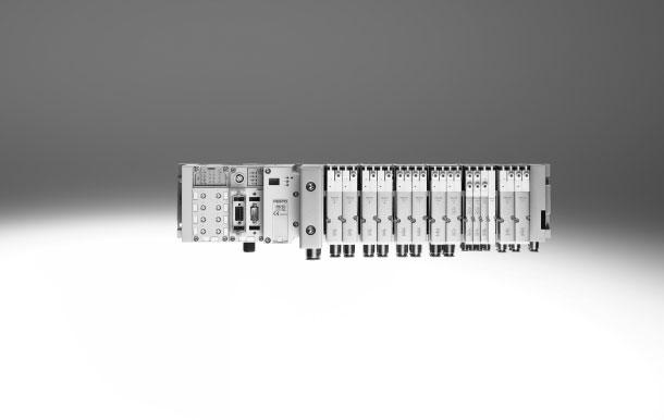
Valve terminals MPA-F
|
|
|
- Gervais Small
- 6 years ago
- Views:
Transcription
1

2 Key features Innovative Versatile Reliable Easy to mount Manifold blocks, tubing connections and exhausts designed for optimum flow rates Tubing diameters: Working ports up to 10 mm Supply ports up to 16 mm MPAF2 flow rates up to 900 l/min Valve terminal with multi-pin plug and fieldbus connections and control block Dream team: fieldbus valve terminal suitable for CPX electrical peripherals. This means: Forward-looking internal communication system for controlling the valves and CPX modules Diagnostics down to the individual valve Valves can be actuated with or without (standard) isolated electrical circuits Modular system offering a range of configuration options Expandable up to 128 solenoid coils Conversions and extensions possible at a later date Selectable pilot air supply Integration of innovative function modules possible Manual pressure regulators, rotatable pressure gauges Pressure sensors integrated on the valve terminal Additional air supply via additional pressure zones using supply plates Wide range of pressures bar Wide range of valve functions Sturdy and durable metal components Valves Manifold blocks Seals Fast troubleshooting thanks to LEDs on the valves and diagnostics via fieldbus Extensive operating voltage range 25% Easy to service through replaceable valves and electronics modules Manual override either non-detenting, detenting or secured against unauthorised activation (covered) Durable, thanks to tried and tested spool valves Large, durable and comprehensive labelling system Tested and ready to install unit Lower selection, ordering, installation and commissioning costs Secure mounting on wall or H-rail Further manifold blocks can be assembled using just two screws and sturdy separating seals on metal separator plates 2 Internet: Subject to change 2016/09
3 Key features Reduced downtimes: Two-colour LED diagnostics on-site Width 10 mm and 20 mm Pneumatic interface to CPX with optional integrated pressure sensor Simple electrical connections Multi-pin plug connection Fieldbus connection Control block Reliable operation: Manual override: non-detenting/detenting or covered Flexible: 64 valve positions/128 solenoid coils (FB) 24 valve positions/24 solenoid coils (MP) Functional: Sturdy metal thread or pre-assembled QS fittings CPX diagnostic interface for handheld devices (channel-oriented diagnostics down to the individual valve) Quick mounting: Directly using screws or on an H-rail, automatic earthing Safe: Operating voltage connection 25%, outputs and valves can be disconnected separately Modular: Supply plates facilitate the creation of multiple pressure zones as well as numerous additional exhaust and supply ports Wide range of valve functions Equipment options Valve functions 5/2-way valve, single solenoid 5/2-way valve, double solenoid 2x 3/2-way valve, normally open 2x 3/2-way valve, normally closed 2x 3/2-way valve, 1x normally open, 1x normally closed 5/3-way valve, mid-position pressurised 5/3-way valve, mid-position closed 5/3-way valve, mid-position exhausted 2x 2/2-way valve, 1x normally closed, 1x normally closed, reversible 2x 2/2-way valve, normally closed 1x 3/2-way valve, normally closed, external compressed air supply 1x 3/2-way valve, normally open, external compressed air supply Manual pressure regulators Pressure sensors can be integrated All valves have the same compact dimensions with an overall length of 107 mm and a width of 10.5 mm or 21 mm. A height of 55 mm makes them a perfect match for the electrical peripherals CPX. Special features Multi-pin plug terminal Max. 24 valve positions/ max. 24 solenoid coils Parallel modular valve linking via circuit boards Electronics module with integrated holding current reduction Any compressed air supply Creating pressure zones Fieldbus terminal/control block Max. 64 valve positions/ max. 128 solenoid coils Internal CPX bus system for valve actuation Module for electrical valve actuation, with or without isolated electrical circuits Any compressed air supply Creating pressure zones Electrical module with extended diagnostics Short circuit detection Open load detection Condition counter Combinable MPAF1 flow rates of up to 360 l/min MPAF2 flow rates of up to 900 l/min MPAF1 and MPAF2 can be combined on one valve terminal Electrical supply plate Increases the maximum number of valve positions possible to 64, with max. 128 solenoid coils Creation of isolated, individually disconnectable electrical circuits (voltage zones) Greater economy thanks to the higher number of valves/solenoid coils per valve terminal Greater safety through individual disconnection of valve groups, for example for EMERGENCY-STOP functions -H- Note The electrical supply plate is available with either an M18 or 7/8 connection. 2016/09 Subject to change Internet: 3
4 Key features Valve terminal configurator The appropriate MPA-F valve terminal can be chosen quickly and easily using the online catalogue. This includes an easy-to-use valve terminal configurator. This makes it much easier to find the right product. The valve terminals are fully assembled according to your order specification and are individually tested. This reduces assembly and installation time to a minimum. The valve terminal MPA-F is ordered using the order code. Ordering system for MPA-F Internet: mpaf Ordering system for CPX Internet: cpx Online via: Multi-pin plug connection The signal flow from the controller to the valve terminal takes place via a pre-assembled or self-assembled multi-wire cable to the multi-pin plug connection, which substantially reduces installation time. The valve terminal can be equipped with max. 24 solenoid coils. This corresponds to 4 to 24 MPA1 or 2 to 24 MPA2 valves, or a combination of both. Versions Sub-D connection Pre-assembled multi-pin cable Multi-pin cable for self-assembly Fieldbus connection via the CPX system An integrated fieldbus node manages communication with a higher-order PLC. This enables a space-saving pneumatic and electronic solution. Valve terminals with fieldbus interfaces can be configured with up to 16 manifold blocks. In conjunction with MPAF1 and 8 solenoid coils per manifold block, up to 128 solenoid coils can thus be actuated. An MPAF2 with 4 solenoid coils per manifold block can actuate 64 solenoid coils. Versions PROFIBUS DP INTERBUS DeviceNet CANopen CC-Link EtherNet/IP PROFINET POWERLINK EtherCAT Sercos III Front End Controller Remote Front End Controller Remote I/O Modbus/TCP CPX terminal Internet: cpx Control block connection via the CPX system Controllers integrated in the Festo valve terminals enable the construction of stand-alone control units to IP65, without control cabinets. Using the slave operation mode, these valve terminals can be used for intelligent pre-processing and are therefore ideal modules for designs using decentralised intelligence. In the master operation mode, valve terminal groups can be designed with many options and functions, which can autonomously control a medium sized machine/system. CPX terminal Internet: cpx 4 Internet: Subject to change 2016/09
5 Key features CP string extension The optional string extension enables additional valve terminals and I/O modules to be connected to the fieldbus node of the CPX terminal. Different input and output modules as well as valve terminals can be connected. The maximum length of the CP string extension is 10 metres, which means that the extension modules can be mounted directly on-site. All of the required electrical signals are transmitted via the CP cable, which in turn means that no further installation is needed on the extension module. The CP string interface offers: 32 input signals 32 output signals for output modules 24 V DC or solenoid coils Logic and sensor supply for the input modules Load voltage supply for the valve terminals Logic supply for the output modules 2016/09 Subject to change Internet: 5
6 Peripherals overview Modular pneumatic components The modular design of the MPA-F facilitates maximum flexibility right from the planning stage and offers maximum ease of servicing during operation. The system consists of manifold blocks and valves. The manifold blocks are screwed together and thus form the support system for the valves. They contain the connection ducts for supplying compressed air to and venting from the valve terminal as well as the working lines for the pneumatic drives for each valve. Each manifold block is connected to the next using three screws. Individual terminal sections can be isolated and further manifold blocks inserted by loosening these screws. This ensures that the valve terminal can be rapidly and reliably extended. Modular electrical peripherals The manner in which the valves are actuated differs according to whether you are using a multi-pin terminal or fieldbus terminal. The MPA-F with CPX interface is based on the internal bus system of the CPX and uses this serial communication system for all solenoid coils and a range of electrical input and output functions. Serial linking facilitates the following: Transmission of switching information High valve density Compact design Position-based diagnostics Separate voltage supply for valves Flexible conversion without address shifting Transmission of status, parameter and diagnostic data Internet: cpx CPX-FEC as autonomous controller with access via Ethernet and web server MPA-F with electrical peripherals CPX Modularity with electrical peripherals CPX 6 Internet: Subject to change 2016/09
7 Peripherals overview Valve terminal pneumatics The manifold blocks are either prepared for: 2 or 4 valves with one solenoid coil 2 or 4 valves with two solenoid coils Valve positions for two solenoid coils can be equipped with any valve or a blanking plate. Valve positions for one solenoid coil can only be equipped with valves of this type (e.g. 5/2-way valve, single solenoid). ac ad ab 9 aj ae 5 8 aa af ag af ah ai 1 bj af ba bb bd af bc 2016/09 Subject to change Internet: 7
8 Peripherals overview Valve terminal pneumatics Designation Brief description Page/Internet 1 Electronics module For connecting MPA1 or MPA2 valves 53 2 Regulator plate Width 10 mm 51 3 Solenoid valve Width 10 mm 50 4 Cover cap for manual override Conversion from detenting/non-detenting to non-detenting or covered 5 Blanking plate For unused valve position (vacant position), width 10 mm 54 6 Vertical pressure shut-off plate The relevant solenoid valve can be switched to unpowered and changed during operation 51 7 Electrical interlinking module For fieldbus connection 53 8 Exhaust plate For ducted exhaust air (port 3/5 combined) 54 9 Exhaust plate For ducted exhaust air (port 3/5 separate) 54 aj Flat plate silencer 55 aa Mounting bracket Optional for valve terminal mounting 53 ab Regulator plate Size 20 mm 51 ac Solenoid valve Size 20 mm 50 ad Blanking plate For unused valve position (vacant position), width 20 mm 54 ae H-rail mounting 53 af Fittings 54 ag Right-hand end plate 52 ah Manifold block For two valve locations, width 20 mm 52 ai Separating seal For manifold block 54 bj Supply plate 54 ba Pressure sensor 52 bb Electrical supply plate For additional power supply for large valve terminals (only with fieldbus) 52 bc Electrical interlinking module For multi-pin plug connection 53 bd Manifold block For four valve locations, width 10 mm 50 8 Internet: Subject to change 2016/09
9 Peripherals overview Valve terminal with multi-pin plug connection Order code: 33P- for the pneumatic components 33E- for the electrical components MPA-F valve terminals with multi-pin plug connection can be expanded by up to 24 solenoid coils The multi-pin plug connection is designed as a removable 25-pin Sub-D connection to IP65. 4 The cable can be selected when ordering: 2.5 m 5 m 10 m Each can be used for max. 8 or 24 valves. 6 5 Designation Brief description Page/Internet 1 Inscription labels Large, for multi-pin plug connection 2 Flat plate silencer For pneumatic interface 55 3 Exhaust plate For ducted exhaust air (port 3/5 separate) 54 4 Exhaust plate For ducted exhaust air (port 3/5 combined) 54 5 Electrical interface For multi-pin plug 52 6 Multi-pin plug connection With multi-pin cable /09 Subject to change Internet: 9
10 Peripherals overview Valve terminal with fieldbus connection, control block (electrical peripherals CPX) Order code: 33P- for the pneumatic components 50E- for the electrical components Valve terminals with fieldbus interfaces can be configured with up to 16 manifold blocks. In conjunction with MPAF1 and 8 solenoid coils per manifold block, up to 128 solenoid coils can thus be actuated. An MPAF2 with 4 solenoid coils per manifold block can actuate 64 solenoid coils. Each valve position can be equipped with any valve or a blanking plate for future extensions. The rules for CPX apply to the equipment that can be used in combination with the electrical peripherals CPX. Digital inputs/outputs Analogue inputs/outputs Parameterisation of inputs and outputs Integrated convenient diagnostic system Preventive maintenance concepts Designation Brief description Page/Internet 1 Exhaust plate For ducted exhaust air (port 5/3 combined) 54 2 Exhaust plate For ducted exhaust air (port 5/3 separate) 54 3 Flat plate silencer For pneumatic interface 55 4 End plate Pneumatic interface for CPX modules 52 5 Electrical interface CPX module 6 Inscription label Large, for end plate 10 Internet: Subject to change 2016/09
11 Key features Pneumatic components Sub-base valve MPA-F offers a comprehensive range of valve functions. All valves are equipped with patented sealing system which facilitates efficient sealing, a broad pressure range and long service life. They have a pneumatic pilot control for optimising performance. Air is supplied by means of pilot air supply. Sub-base valves can be quickly replaced since the tubing connectors remain on the manifold block. This design is also particularly flat. Irrespective of the valve function there are sub-base valves with one solenoid coil (single solenoid) or with two solenoid coils (double solenoid or two single solenoid valves in one housing). Constructional design Valve replacement The valves are attached to the metal manifold block using two screws, which means that they can be easily Extension replaced. The mechanical sturdiness of the manifold block guarantees excellent long-term sealing. Blanking plates can be replaced by valves at a later date. The dimensions, mounting points and existing pneumatic installations remain unchanged during this process. The valve code (M, MS, MU, J, N, NS, NU, K, KS, KU, H, HS, HU, B, G, E, X, W, D, DS, I) is located on the front of the valve beneath the manual override. 5/2-way valve Code Circuit symbol Width Description [mm] M 10, 20 MS 10, 20 Single solenoid Pneumatic spring return Reversible Operating pressure 0,9 +10 bar Single solenoid Mechanical spring return Reversible Operating pressure 0,9 +8 bar MU 10 Single solenoid Polymer poppet valve Mechanical spring return Reversible Operating pressure 0,9 +10 bar J 10, 20 Double solenoid Reversible Operating pressure 0,9 +10 bar 2016/09 Subject to change Internet: 11
12 Key features Pneumatic components 2x 3/2-way valve Code Circuit symbol Width Description [mm] N 10, 20 Single solenoid Normally open Pneumatic spring return Operating pressure 3 10 bar NS 10, 20 Single solenoid Normally open Mechanical spring return Reverse operation Operating pressure bar NU 10 Single solenoid Polymer poppet valve Normally open Mechanical spring return Reverse operation Operating pressure bar K 10, 20 Single solenoid Normally closed Pneumatic spring return Operating pressure 3 10 bar KS 10, 20 Single solenoid Normally closed Mechanical spring return Reverse operation Operating pressure bar KU 10 Single solenoid Polymer poppet valve Normally closed Mechanical spring return Reverse operation Operating pressure bar H 10, 20 HS 10, 20 Single solenoid Normal position 1x closed 1x open Pneumatic spring return Operating pressure 3 10 bar Single solenoid Normal position 1x closed 1x open Mechanical spring return Reverse operation Operating pressure bar HU 10 Single solenoid Polymer poppet valve Normal position 1x closed 1x open Mechanical spring return Reverse operation Operating pressure bar 12 Internet: Subject to change 2016/09
13 Key features Pneumatic components 5/3-way valve Code Circuit symbol Width Description [mm] B 10, 20 Mid-position pressurised 1) Mechanical spring return Reverse operation Operating pressure bar G 10, 20 Mid-position closed 1) Mechanical spring return Reverse operation Operating pressure bar E 10, 20 Mid-position exhausted 1) Mechanical spring return Reverse operation Operating pressure bar 1) If neither solenoid coil is energised, the valve moves to its mid-position by means of spring force. If both coils are energised at the same time, the valve remains in the previously assumed switching position. 3/2-way valve Code Circuit symbol Width Description [mm] W 10, 20 X 10, 20 Single solenoid Normally open External compressed air supply Pneumatic spring return Reverse operation Operating pressure bar Compressed air ( bar) supplied at working port 2 can be switched with both internal and external pilot air supply. Single solenoid Normally closed External compressed air supply Pneumatic spring return Reverse operation Operating pressure bar Compressed air ( bar) supplied at working port 4 can be switched with both internal and external pilot air supply. 2016/09 Subject to change Internet: 13
14 Key features Pneumatic components 2x 2/2-way valve Code Circuit symbol Width Description [mm] D 10, 20 Single solenoid Normally closed Pneumatic spring return Operating pressure 3 10 bar DS 10, 20 I 10, 20 Single solenoid Normally closed Mechanical spring return Reverse operation Operating pressure bar Single solenoid 1x normally closed 1x normally closed, reverse operation Pneumatic spring return Operating pressure 3 10 bar Vacuum at port 3/5 only -H- Note A filter must be installed upstream of valves operated in vacuum mode. This prevents any foreign matter in the intake air getting into the valve (e.g. when operating a suction cup). 14 Internet: Subject to change 2016/09
15 Key features Pneumatic components Vertical stacking Additional function units can be added to each valve position between the sub-base and the valve. These units are known as vertical stacking modules and enable special functioning or control of an individual valve position. Pressure regulator plate An adjustable pressure regulator can be installed between the sub-base and the valve in order to control the force of the triggered actuator. This pressure regulator maintains an essentially constant output pressure (secondary side) independent of pressure fluctuations (primary side) and air consumption. Standard version: For supply pressure up to 6 bar or up to 10 bar Without pressure gauge (optional) Regulator knob with 3 positions (locked, reference position, free running) Vertical pressure shut-off plate for MPA1 The vertical pressure shut-off plate can be used to hot swap individual valves without switching off the overall air supply. It allows the working pressure for the individual valve to be switched off manually via the actuating element. 2016/09 Subject to change Internet: 15
16 Key features Pneumatic components Vertical stacking Vertical stacking components, MPA1 Vertical stacking components, MPA Valve VMPA1 2 Valve VMPA1, mounting screws replaced by long version (included in the scope of delivery of the regulator plate) 3 Vertical pressure shut-off plate VMPA1-HS 4 Regulator plate VMPA1 5 Manifold sub-base 1 Valve VMPA2 2 Regulator plate VMPA2 3 Manifold sub-base 16 Internet: Subject to change 2016/09
17 Key features Pneumatic components Vertical stacking Mode of operation of pressure regulator plate (P regulator) for port 1; code: PA, PF This pressure regulator regulates the pressure upstream of the valve in duct 1. Ducts 2 and 4 thus have the same regulated pressure. During venting, the exhaust flow in the valve is from duct 2 to duct 3 and from duct 4 to duct 5. Advantages The pressure regulator is not affected by venting, since the pressure is regulated upstream of the valve. Application examples The pressure regulator can always be adjusted and read, since the pressure from the valve terminal is always present. An equal working pressure is required at working ports 2 and 4. A lower working pressure (e.g. 3 bar) than the operating pressure present on the valve terminal (e.g. 8 bar) is required. Mode of operation of the pressure regulator plate (B regulator) for port 2; code: PC, PH This pressure regulator regulates the pressure in duct 2 after the pressure medium flows through the valve. During venting, the exhaust flow in the valve is from duct 2 to duct 3 via the pressure regulator. Restrictions The pressure regulator can only be adjusted in switched state (e.g. the valve is switched to 2 and exhaust flow is from 4 to 5). Application example Reduced pressure at port 2. Operating pressure at port /09 Subject to change Internet: 17
18 Key features Pneumatic components Vertical stacking Mode of operation of the pressure regulator plate (A regulator) for port 4; code: PB, PK This pressure regulator regulates the pressure in duct 4 after the pressure medium flows through the valve. During venting, the exhaust flow in the valve is from duct 4 to duct 5 via the pressure regulator. Restrictions The pressure regulator can only be adjusted in switched state (e.g. the valve is switched to 4 and exhaust flow is from 2 to 3). Application example Reduced pressure at port 4. Operating pressure at port 2. Mode of operation of the pressure regulator plate (B regulator, reversible) for port 2, reversible; code: PL, PN The reversible B regulator splits the supply air in duct 1 and regulates the pressure upstream of the valve in duct 3 (the unregulated pressure from duct 1 is in duct 5). The regulated air is then supplied to duct 2. The valve is thus operated in reversible mode. During venting, the exhaust flow in the valve is from duct 2 to duct 1 and it is reversed into the manifold block via the intermediate plate to duct 3. Application examples When instead of the operating pressure of the valve terminal, a different pressure is required in duct 2. When fast venting is required. When the pressure regulator must always be adjustable. -H- Note Reversible pressure regulator plates may only be combined with valves that can be operated in reversible mode. Advantages Fast cycle times. 50% higher exhaust flow rate, as air is not exhausted via the pressure regulator. The load on the pressure regulator is also reduced. No quick exhaust valves are required. Restrictions Operating pressure is always present at the pressure regulator, as the pressure is regulated upstream of the valve, i.e. the regulator can always be adjusted. 2x 3/2-way valves (code N, K, H) are not used, as pressure is present at ports 3 and Internet: Subject to change 2016/09
19 Key features Pneumatic components Vertical stacking Mode of operation of the pressure regulator plate (A regulator, reversible) for port 4, reversible; code: PK, PM The reversible A regulator splits the working air in duct 1 and supplies the pressure upstream of the valve into duct 5 (the unregulated pressure from duct 1 is in duct 3). The regulated air is then supplied to duct 4. The valve is thus operated in reversible mode. During venting, the exhaust flow in the valve is from duct 4 to duct 1 and it is reversed into the manifold block via the intermediate plate to duct 5. Application examples When instead of the operating pressure of the valve terminal, a different pressure is required in duct 4. When fast venting is required. When the pressure regulator must always be adjustable. -H- Note Reversible pressure regulator plates may only be combined with valves that can be operated in reversible mode. Advantages Fast cycle times. 50% higher exhaust flow rate, as air is not exhausted via the pressure regulator. The load on the pressure regulator is also reduced. No quick exhaust valves are required. Restrictions Operating pressure is always present at the pressure regulator, as the pressure is regulated upstream of the valve, i.e. the regulator can always be adjusted. 2x 3/2-way valves (code N, K, H) cannot be used, as pressure is present at ports 3 and /09 Subject to change Internet: 19
20 Key features Pneumatic components Vertical stacking Pressure regulator plate Code Type Width Supply pressure Description [mm] 6 bar 10 bar Pressure regulator plate for port 1 (P regulator) PA VMPA1-B8-R1-M5-10 VMPA1-B8-R1C2-C-10 VMPA2-B8-R1C2-C-10 PF VMPA1-B8-R1-M5-06 VMPA1-B8-R1C2-C-06 VMPA2-B8-R1C2-C Regulates the operating pressure in duct 1 upstream of the directional control valve Pressure regulator plate for port 2 (B regulator) PC VMPA1-B8-R2-M5-10 VMPA1-B8-R2C2-C-10 VMPA2-B8-R2C2-C Regulates the operating pressure in duct 2 downstream of the directional control valve PH VMPA1-B8-R2-M5-06 VMPA1-B8-R2C2-C-06 VMPA2-B8-R2C2-C Pressure regulator plate for port 4 (A regulator) PB VMPA1-B8-R3-M5-10 VMPA1-B8-R3C2-C-10 VMPA2-B8-R3C2-C Regulates the operating pressure in duct 4 downstream of the directional control valve PG VMPA1-B8-R3-M5-06 VMPA1-B8-R3C2-C-06 VMPA2-B8-R3C2-C Pressure regulator plate for port 2, reversible (B regulator) PL VMPA2-B8-R6C2-C Reversible pressure regulator to port 2 PN VMPA2-B8-R6C2-C Pressure regulator plate for port 4, reversible (A regulator) PK VMPA2-B8-R7C2-C Reversible pressure regulator to port 4 PM VMPA2-B8-R7C2-C Internet: Subject to change 2016/09
21 Key features Pneumatic components Blanking plate Plate without valve function for reserving valve positions on a valve terminal. Valves and blanking plates are attached to the manifold block using two screws. Valve function Code Circuit symbol Width Description [mm] L For valve terminal only: Blanking plate for vacant valve position Compressed air supply and venting Pneumatic interface Supply plate The valve terminal MPA-F can be supplied with air at one or more points. The duct and supply cross sections of the MPA-F are extremely effectively sized. Additional supply plates are not generally required. The main supply to the valve terminal is located on the pneumatic interface, which links the electrical and the pneumatic parts. Additional provision is made for a number of supply plates. Venting is either via flat plate silencers or common ports for ducted exhaust. These vents are located on the pneumatic interface as well as on the supply plates. The exhaust air is always vented via port 82/84 on the right-hand end plate. Pneumatic interface with integrated pressure sensor The pneumatic interface is available in a version with integrated pressure sensor for duct 1. The display shows the numerical value for the monitored pressure. The LEDs psi and bar indicate the pressure value unit. Three further LEDs indicate whether the applied pressure exceeds, conforms to or falls below the setpoint value. You can parameterise the pressure sensor via the PLC or the handheld device (CPX-MMI) from Festo. 2016/09 Subject to change Internet: 21
22 Key features Pneumatic components Compressed air supply and venting Work air supply Power supply module with exhaust plate Pneumatic interface with left-hand end plate Exhaust duct 3 and duct 5 separate Exhaust duct 3/5 common with venting via flat plate silencer, duct 3/5 common The valve terminal MPA-F can be supplied with pressure at one or more points. This is a reliable way of ensuring that all functional components will always offer good performance, even with large-scale extensions. The valve terminal is supplied via the left-hand end plate or power supply modules. Exhaust port 3/5 is either vented via silencers or ports for ducted exhaust air on the power supply modules and on the left-hand end plate. Pilot air supply The port for the pilot air supply (port 12/14) is always on the righthand end plate. The ports differ for the following types of pilot air supply: Internal External Internal pilot air supply Internal pilot air supply can be selected if the required working pressure is between 3 and 8 bar. This is done by setting the pilot air supply in the right-hand end plate to this operating mode via a selector switch. The pilot air is branched from port 1 using an internal connection. Port 12/14 must be sealed using a blanking plug. External pilot air supply If the supply pressure is less than 3 bar or greater than 8 bar, you must operate your MPA-F valve terminal with external pilot air supply. This is done by feeding the pilot air supply via port 12/14 on the righthand end plate. Port 12/14 is equipped with fittings for this purpose. The selector switch must be set to the appropriate operating mode. -H- Note If a gradual pressure build-up is required in the system by means of a soft-start valve, then external pilot air should be selected whereby the pilot pressure is already applied at the point of switch-on. Right-hand end plate with selector switch Internal pilot air supply External pilot air supply For end plates with selector switch, the outgoing direction of the ports is to the front of the valve terminal. This means that all of the ports on the terminal can be combined in one outgoing direction. A special feature of the right-hand end plate is the selector switch that can be set to two different pilot air supply versions. End plates with selector switch set at the factory for: Internal pilot air supply External pilot air supply 22 Internet: Subject to change 2016/09
23 Key features Pneumatic components Right-hand end plate Code Type of compressed air supply and pilot air supply Description End plate with selector switch, internal pilot air supply S, V, Y Internal pilot air supply Pilot air supply is branched internally from port 1 Ports 1 and 12/14 are internally connected Port 12/14 is sealed with a blanking plug Pilot exhaust air via port 82/84 End plate with selector switch, external pilot air supply T, X, Z External pilot air supply Pilot air supply is connected at port 12/14 Pilot exhaust air via port 82/84 Pneumatic interface with left-hand end plate Code Pneumatic interface design variants Notes Graphical symbol Type M VMPAF-FB-EPL VMPAF-FB-EPLM Pneumatic interface for CPX plastic interlinking module Pneumatic interface for CPX metal interlinking module MIPE VMPAF-FB-EPL-PS VMPAF-FB-EPLM-PS Pneumatic interface for CPX plastic interlinking module, with integrated pressure sensor for duct 1 Pneumatic interface for CPX metal interlinking module, with integrated pressure sensor for duct 1 M VMPAF-MPM-EPL Pneumatic interface for multi-pin plug connection 2016/09 Subject to change Internet: 23
24 Key features Pneumatic components Pneumatic supply plate (power supply module) The ducts and supply cross sections of the MPA-F are extremely effectively sized. Additional supply plates are not generally required. Supply plates can be configured at any point upstream or downstream of manifold blocks for the creation of pressure zones. The pilot exhaust port 82/84 is always vented via the right-hand end plate. Supply plates contain the ports: Compressed air supply (1) Exhaust air (3/5) Depending on your order, the exhaust ducts are either ducted or vented via the flat plate silencer. The supply plate is configured using the code letter U if no directly adjoining separating seal is required. If a separating seal (S, T or R) is selected directly to the right or left of the supply plate, then the code letter V or W identifies the position of the left-hand or right-hand separating seal. The code for the separating seal (S, T or R) is placed in front of the code for the supply plate (V or W). Pneumatic supply plate (power supply module) Code 1) Graphical symbol Type Notes U VMPAF-SP-P Supply plate without separating seal (no R, S or T selected) V VMPAF-SP-P Supply plate with separating seal on left, if R, S or T selected W VMPAF-SP-P Supply plate with separating seal on right, if R, S or T selected 1) The supply plate is equipped with silencer or exhaust plate depending on the code for the air supply S, T, V, X. 24 Internet: Subject to change 2016/09
25 Key features Electrical components Electrical supply plate Additional electrical supply plates can be used for larger terminals. This enables up to 64 valve positions/128 solenoid coils to be supplied. MPA-F with CPX Electrical supply plates can be configured at any point upstream or downstream of manifold blocks. -H- Note Please note that only electrical modules with isolated electrical circuits are permissible to the right of the electrical supply plate. The electrical supply plate must not be installed directly to the left of a pneumatic supply plate (type VMPA-FB-SP-P). Electrical supply plate Code Graphical symbol Type Notes L VMPA-FB-SP-V Electrical supply plate with M18 plug connection, 3-pin VMPA-FB-SP-7/8-V-5POL Electrical supply plate with 7/8 plug connection, 5-pin VMPA-FB-SP-7/8-V-4POL Electrical supply plate with 7/8 plug connection, 4-pin Pin allocation for power supply Pin allocation for M18 Pin Allocation 2 24 V DC valves 3 0 VDC 4 FE Pin allocation for 7/8, 5-pin 1 0 V DC valves 2 n.c. 3 FE (leading) 4 n.c V DC valves Pin allocation for 7/8, 4-pin A B C D n.c. 24 V DC valves FE 0 V DC valves (leading) 2016/09 Subject to change Internet: 25
26 Key features Pneumatic components Creating pressure zones and separating exhaust air with separating seals MPA-F offers a number of options for creating pressure zones if different working pressures are required. Depending on the electrical interface, up to 16 pressure zones are possible. Pressure zones are created by isolating the internal supply ducts between the manifold blocks using an appropriate separating seal. Compressed air is supplied and vented via a supply plate. The position of the supply plates and separating seals can be freely selected with the valve terminal MPA-F. Separating seals are integrated ex-works as per your order. Separating seals can be distinguished through their coding, even when the valve terminal is assembled. Creating pressure zones Code Separating seal Notes Pictorial examples Coding No duct separation T VMPAF-DP Duct 1 separated S VMPAF-DP-P Duct 1 and 3/5 separated R VMPAF-DP-PRS Duct 3/5 separated VMPAF-DP-RS 26 Internet: Subject to change 2016/09
27 Key features Pneumatic components Creating pressure zones with duct separation in the manifold block A pressure zone is created here by isolating the internal supply ducts using a separator that is firmly integrated in the manifold block (code I). Compressed air is supplied and vented via a supply plate. Manifold blocks with firmly integrated duct separation can be distinguished by their coding, even when the valve terminal is assembled. Creating pressure zones Code Manifold block with duct separation for operating with flat plate silencer or with ducted exhaust air Notes Pictorial examples Coding I Duct 1 separated -H- Note The duct separation cannot be subsequently removed and is integrated in the centre of the manifold block: With width 10 mm between valves 2 and 3 With width 20 mm between valves 1 and 2 Examples: Creating pressure zones Manifold block with pressure zone separation in duct 1 Another way of creating pressure zones is to use manifold blocks with pressure zone separation. The diagram opposite shows the version with pressure zone separation in duct 1. Zone 1 Zone /09 Subject to change Internet: 27
28 Key features Pneumatic components Examples: Compressed air supply and pilot air supply Internal pilot air supply, flat plate silencer Air supply to the valve terminal: code S The diagram opposite shows an example of the configuration and connection of the air supply with internal pilot air supply. Port 12/14 on the right-hand end plate is sealed with a blanking plug. The selector switch on the right-hand end plate must also be set accordingly. The exhaust port 3/5 is vented via the flat plate silencer. The pilot exhaust port 82/84 is always vented via the right-hand end plate. Separating seals can be used optionally to create pressure zones. Optional separating seal External pilot air supply, flat plate silencer Air supply to the valve terminal: code T The diagram opposite shows an example of the configuration and connection of the compressed air supply with external pilot air supply. The external pilot air supply is fed to port 12/14 via the right-hand end plate. The selector switch on the right-hand end plate must also be set accordingly. The exhaust port 3/5 is vented via the flat plate silencer. The pilot exhaust port 82/84 is always vented via the right-hand end plate. Separating seals can be used optionally to create pressure zones. Optional separating seal 28 Internet: Subject to change 2016/09
29 Key features Pneumatic components Examples: Compressed air supply and pilot air supply Internal pilot air supply, ducted exhaust air Air supply to the valve terminal: code V or Y The diagram opposite shows an example of the configuration and connection of the compressed air supply with internal pilot air supply. Port 12/14 on the right-hand end plate is sealed with a blanking plug. The selector switch on the right-hand end plate must also be set accordingly. The exhaust port 3/5 is vented via the corresponding ports. The pilot exhaust port 82/84 is always vented via the right-hand end plate. Separating seals can be used optionally to create pressure zones. Optional separating seal External pilot air supply, ducted exhaust air Air supply to the valve terminal: code X or Z The diagram opposite shows an example of the configuration and connection of the compressed air supply with external pilot air supply. The external pilot air supply is fed to port 12/14 via the right-hand end plate. The selector switch on the right-hand end plate must also be set accordingly. The exhaust port 3/5 is vented via the corresponding ports. The pilot exhaust port 82/84 is always vented via the right-hand end plate. Separating seals can be used optionally to create pressure zones. Optional separating seal 2016/09 Subject to change Internet: 29
30 Key features Pneumatic components Manifold block MPA-F is based on a modular system consisting of manifold blocks and valves. The manifold blocks are screwed together and thus form the support system for the valves. They contain the connection ducts for supplying compressed air to and venting from the valve terminal as well as the working lines for the pneumatic actuators for each valve. Each manifold block is connected to the next using two screws. Individual terminal sections can be isolated and further manifold blocks inserted by loosening these screws. This ensures that the valve terminal can be rapidly and reliably extended. Manifold block versions Code Graphical symbol Type Width Number of valve positions Notes [mm] (solenoid coils) Manifold block for multi-pin plug/fieldbus connection A, C 1) AI, CI 1) VMPAF-AP-4-1 VMPAF-AP-4-1-T (8) Working ports (2, 4) on the manifold block Connection sizes: MPAF1: M7, QS4, QS6 Code I: Separation in duct 1 in the manifold block B, D 1) BI, DI 1) VMPAF-AP-2-2 VMPAF-AP-2-2-TO 20 2 (4) Working ports (2, 4) on the manifold block Connection sizes MPAF2: G¼, QS8, QS10 Code I: Separation in duct 1 in the manifold block 1) Only possible with multi-pin plug connection 30 Internet: Subject to change 2016/09
31 Key features Pneumatic components Pressure sensor Red LED: Pressure exceeded 2 Green LED: Pressure conforms to 3 Red LED: Pressure fallen below 4 Red LED: Common error display The pressure sensor indicates whether the applied pressure exceeds, conforms to or falls below the setpoint value using three LEDs. An additional LED indicates common errors (limit exceeded or fallen below). The limits for pressure monitoring are set by means of parameter settings. You can parameterise the pressure sensor plate via the PLC or the handheld device (CPX-MMI-1) from Festo. The pressure in the exhaust ducts (3/5) and the process pressure (external) can also be measured. Pressure measurement in the exhaust ducts is used for monitoring the operating pressure during reversible operation (supply to 3/5). Pressure sensor versions Code Graphical symbol Type Use PE VMPAF-FB-PS-1 Monitoring the operating pressure in duct 1 PF VMPAF-FB-PS-3/5 Monitoring the pressure in exhaust ducts 3 and 5 (pressure monitoring for reversible valve terminal) PG VMPAF-FB-PS-P1 Monitoring an external process pressure Left-hand end plate with integrated pressure sensor Red LED: Upper limit exceeded 2 Green LED: Pressure in nominal range 3 Display 4 Red LED: Limit not reached 5 Red LED: Common error display 6 Yellow LED: Value in display shown in bar 7 Yellow LED: Value in display shown in psi The left-hand end plate with pneumatic interface can be equipped with an integrated pressure sensor. The pressure sensor measures the operating pressure in duct 1. The measured value is displayed numerically and sent to the master controller via the CPX bus node by means of serial linking. This ensures that the system part in question is always operated above a required minimum pressure, but not in the range of excess pressures, which can impair operation. 2016/09 Subject to change Internet: 31
32 Key features Pneumatic components Electrical interface versions Code Graphical symbol Type Width [mm} Number of valve positions (solenoid coils) Notes Electronics module for multi-pin plug A, B, C, D VMPA1-MPM-EMM-8 VMPA1-MPM-EMM-4 VMPA2-MPM-EMM-4 VMPA2-MPM-EMM (8) 4 (4) 20 2 (4) 2 (2) Each solenoid coil must be assigned to a specific pin of the multi-pin plug in order for the valve to be actuated. Regardless of the blanking plates or valves used, valve positions occupy 1 address for actuation of 1 coil 2 addresses for actuation of 2 coils Electronics module for fieldbus with standard diagnostics A, B, AH, BH VMPA -FB-EMS- VMPA -FB-EMG- VMPA -FB-EMS- VMPA -FB-EMG (8) 2 (4) The electronics module contains the serial communication system and facilitates: Transmission of switching information Actuation of up to 8 solenoid coils Position-based diagnostics Separate voltage supply for valves Transmission of status, parameter and diagnostic data There are different versions: Without isolated electrical circuit (VMPA -FB-EMS- ) With isolated electrical circuit (VMPA -FB-EMG- ) Diagnostic function: Error: Load voltage of the valves Electronics module for fieldbus with extended diagnostic function A, B, AH, BH with: D2 VMPA -FB-EMS- -D2 VMPA -FB-EMG- -D2 VMPA -FB-EMS- -D2 VMPA -FB-EMG- -D (8) 2 (4) The electronics module with extended diagnostic function contains the same functions as the electronics module with standard diagnostics. The diagnostic function, however, has been extended: Error: Load voltage of the valves Error: Wire break (open load) Error: Short circuit in load voltage of valves Message: Condition monitoring -H- Note Multi-pin plug with modular linking Manifold blocks MPAF1 and MPAF2 can be combined as required Positive or negative switching actuation is possible (mixed operation is not permitted) Double solenoid valves cannot be mounted on single solenoid electronics modules Single solenoid valves can be mounted on double solenoid electronics modules 32 Internet: Subject to change 2016/09
33 Key features Pneumatic components Ports for supply and exhaust Code Connection Designation Plug connector, large Plug connector, small Code D Thread for supply S Internal pilot air supply, silencer 1 Supply air/ vacuum supply Push-in fitting QS-G½-16 QS-G½-12 QS-1/2-1/2-I-U-M 3/5 Exhaust air Flat plate silencer 12/14 Pilot air supply 82/84 Pilot exhaust air Push-in fitting QS-G¼-10-I QS-1/4-3/8-I-U-M QS-G¼-8-I QS-1/4-5/16-I-U-M G½ G¼ Silencer G¼ T External pilot air supply, silencer 1 Supply air/ vacuum supply Push-in fitting QS-G½-16 QS-G½-12 QS-1/2-1/2-I-U-M 3/5 Exhaust air Flat plate silencer 12/14 Pilot air supply Push-in fitting QS-G¼-10-I QS-G¼-8-I G¼ QS-1/4-3/8-I-U-M QS-1/4-5/16-I-U-M 82/84 Pilot exhaust air Push-in fitting QS-G¼-10-I QS-1/4-3/8-I-U-M QS-G¼-8-I QS-1/4-5/16-I-U-M G½ G¼ Silencer G¼ V, Y Internal pilot air supply, ducted exhaust air 1 Supply air/ vacuum supply Push-in fitting QS-G½-16 3/5 Exhaust air Push-in fitting QS-G½-16 QS-G½-12 QS-1/2-1/2-I-U-M QS-G½-12 QS-1/2-1/2-I-U-M 12/14 Pilot air supply 82/84 Pilot exhaust air Push-in fitting QS-G¼-10-I QS-G¼-8-I G¼ QS-1/4-3/8-I-U-M QS-1/4-5/16-I-U-M G½ G½ X, Z External pilot air supply, ducted exhaust air 1 Supply air/ vacuum supply Push-in fitting QS-G½-16 3/5 Exhaust air Push-in fitting QS-G½-16 12/14 Pilot air supply Push-in fitting QS-G¼-10-I QS-1/4-3/8-I-U-M 82/84 Pilot exhaust air Push-in fitting QS-G¼-10-I QS-1/4-3/8-I-U-M QS-G½-12 QS-1/2-1/2-I-U-M QS-G½-12 QS-1/2-1/2-I-U-M QS-G¼-8-I QS-1/4-5/16-I-U-M QS-G¼-8-I QS-1/4-5/16-I-U-M G½ G½ G¼ G¼ Silencer G¼ 2016/09 Subject to change Internet: 33
34 Key features Assembly Valve terminal assembly Sturdy terminal mounting thanks to: Four through-holes for wall mounting Additional mounting brackets H-rail mounting -H- Note When wall-mounting MPA-F valve terminals with more than 4 manifold blocks, use additional mounting brackets of the type VMPA-BG-RW to prevent damage to the valve terminal. The mounting brackets can be mounted on the pneumatic supply plates. Wall mounting Multi-pin plug connection The MPA-F valve terminal is screwed onto the mounting surface using four M6 screws. The mounting holes are on the pneumatic interface and on the right-hand end plate. Optional mounting brackets are also available. Wall mounting Fieldbus connection The MPA-F valve terminal is screwed onto the mounting surface using six M6 screws. The mounting holes are on the left-hand end plate (CPX) and on the right-hand end plate (MPA-F). The pneumatic interface also provides further mounting holes as well as optional mounting brackets. H-rail mounting A B The MPA-F valve terminal is attached to the H-rail (see arrow A). The valve terminal MPA-F is then swivelled onto the H-rail and secured in place with the clamping components (see arrow B). For H-rail mounting of the valve terminal you will need the following MPA-F mounting kit: With multi-pin plug: CPA-BG-NRH With fieldbus: VMPAF-FB-BG-NRH This enables mounting of the valve terminal on a H-rail to EN Internet: Subject to change 2016/09
35 Key features Display and operation Display and operation Each solenoid coil is allocated an LED that indicates its signal status. Indicator 12 shows the signal status of the coil for output 2 Indicator 14 shows the signal status of the coil for output 4 Manual override The manual override (MO) enables the valve to be actuated when not electrically activated or energised. The valve is switched by pushing the manual override. The set switching status can also be locked by turning the manual override (code R or as accessory). Alternatives: A cover (code N or as accessory) can be fitted over the manual override to prevent it from being locked. The manual override can then only be activated by pushing it. A cover (code V) can be fitted over the manual override to prevent it from being accidentally activated. Pneumatic connection and control elements Flat plate silencer for exhaust port 3/5 2 Manual override (for each pilot solenoid coil, non-detenting or non-detenting/detenting) 3 Adjusting knob for optional pressure regulator plate 4 Working ports 2 and 4, for each valve position 5 Supply port 1 6 Pressure gauge (optional) -H- Note A manually actuated valve (manual override) cannot be reset electrically. Conversely, an electrically actuated valve cannot be reset using the mechanical manual override Electrical connection and display components for fieldbus Power supply connection 2 Earthing screw 3 Fieldbus connection (bus-specific) 4 Service interface for handheld unit, etc. 5 Pneumatic interface with optional integrated pressure sensor 6 Diagnostic LEDs for valves 2016/09 Subject to change Internet: 35
36 Key features Display and operation Manual override (MO) MO with automatic return (non-detenting) Press in the stem of the MO with a pin or screwdriver. Pilot valve switches and actuates the main valve. 2 Remove the pin or screwdriver. Spring force pushes the stem of the MO back. Pilot valve returns to the initial position and so too the single solenoid main valve (not with double solenoid valve code J). MO set via turning (detenting) Press in the stem of the MO with a pin or screwdriver until the valve switches and then turn the stem clockwise by 90 until the stop is reached. Valve remains switched. 2 Turn the stem anti-clockwise by 90 until the stop is reached and then remove the pin or screwdriver. Spring force pushes the stem of the MO back. Valve returns to initial position (not with double solenoid valve code J). Identification system Inscription panel approx. 20 x 45 mm Inscription label holder VMPAF-ST1 VMPAF-ST1T Retainer VMPAF-STH An inscription label holder VMPAF-ST1 (Part No , code T in the order code, for holding paper labels) or VMPAF-ST1T (Part No , for holding IBS-9x20 inscription labels) can be mounted on each manifold rail for labelling the valves. Large inscription labels (20 x 45 mm) can be attached to the pneumatic interface as an alternative or in addition to the smaller labels. Inscription label holders can be applied on different sides using circular clips in order to identify pneumatic threaded connectors, solenoid coils or manual override tools, for example. Inscription panel approx. 20 x 45 mm Retainer VMPAF-STH Inscription label holder VMPAF-ST1 VMPAF-ST1T 36 Internet: Subject to change 2016/09
37 Key features Electrical components Electrical power as a result of current reduction Power management Each MPA solenoid coil is protected with a spark arresting protective circuit as well as against polarity reversal. All valve types are additionally equipped with integrated current reduction. MPA valves are supplied with operating voltage in the range V (24 V +/ 25%). This high tolerance is made possible through integrated control electronics and offers additional security, e.g. if the operating voltage drops. Individual valve Valves can also be used on individual sub-bases for actuators further away from the valve terminal. Detachable electronics module with integrated holding current reduction Electrical M8 connection, 4-pin with screw connection -H- Note Further information can be found on: VMPA1 Electrical multi-pin plug connection The following multi-pin plug connection is offered for the valve terminal MPA-F: Sub-D multi-pin plug connection (25-pin) Pins 1 24 are used for addresses 1 24 in order. If fewer than 24 addresses are used for the valve terminal, the remaining pins up to 24 are left free. Pin 25 is reserved for the neutral conductor. The valves are switched by means of positive or negative logic (PNP or NPN). Mixed operation is not permitted. Each pin on the multi-pin plug can actuate exactly one valve solenoid coil. If the maximum configurable number of valve positions is 24, this means that 24 valves, each with a single solenoid coil, can be addressed. With 12 or fewer valve positions, 2 solenoid coils per valve can be addressed. With 12 or more valve positions, the number of available valve positions for valves with two solenoid coils decreases. -H- Note If a single solenoid valve is assembled on a double solenoid valve position, the second address is also occupied and cannot be used. CPX fieldbus connection All functions and features of the electrical peripherals CPX are permitted in connection with the CPX interface. This means: The valves and electrical outputs are supplied via the operating voltage connection CPX The valves are supplied and disconnected separately via a separate valve connection on the CPX (code V) -H- Note Further information can be found on: Internet: cpx Guidelines on addressing for valves/solenoid coils The maximum possible number of addresses with a multi-pin plug connection is 24 Each manifold block/electronics module occupies a defined number of addresses/pins: Manifold rail MPAF1 for 4 single solenoid valves: 4 Manifold rail MPAF1 for 4 double solenoid valves: 8 Manifold rail MPAF2 for 2 single solenoid valves: 2 Manifold rail MPAF2 for 2 double solenoid valves: 4 The numbering of the addresses goes from left to right in ascending consecutive order. The following applies to the individual valve positions: address x for coil 14 and address x+1 for coil 12 If single solenoid valves are mounted on manifold blocks for double solenoid valves, the address of coil 12 and the assigned pin will remain unused 2016/09 Subject to change Internet: 37
38 Key features Electrical components Pin allocation Sub-D socket, cable Pin Address/coil Wire colour 2) Pin Address/coil Wire colour 2) 1 0 WH WH PK 2 1 GN PK BN 3 2 YE WH BU 4 3 GY BN BU 5 4 PK WH RD 6 5 BU BN RD 7 6 RD WH BK 8 7 VT BN 9 8 GY PK 25 0 V 1) BK 10 9 RD BU WH GN -H- Note BN GN WH YE YE BN WH GY GY BN The drawing shows a view on the Sub-D socket on the multi-pin cable VMPA-KMS1-. 1) 0 V for positive switching control signals; connect 24 V for negative switching control signals; mixed operation is not permitted. 2) To IEC 757 Dimensions Connecting cables Download CAD data 1 Cable connector with clamping range 6 12 mm The wire colours refer to the following pre-assembled multi-pin cables from Festo: VMPA-KMS1-8- Valve terminal for up to 4 valve positions (8 coils) VMPA-KMS1-24- Valve terminal with 8 24 valve positions Type L1 L2 B1 H1 H2 H3 VMPA-KMS-H Type Sheath Length Wire x mm 2 D Part No. [m] [mm] VMPA-KMS PVC x VMPA-KMS PUR PUR x VMPA-KMS1-8-5 PVC 5 10 x VMPA-KMS2-8-5-PUR PUR 5 10 x VMPA-KMS PVC x VMPA-KMS PUR PUR x VMPA-KMS PVC x VMPA-KMS PUR PUR x VMPA-KMS PVC 5 25 x VMPA-KMS PUR PUR 5 25 x VMPA-KMS PVC x VMPA-KMS PUR PUR x VMPA-KMS-H Cover for self-assembly Internet: Subject to change 2016/09
39 Key features Electrical components Instructions for use System equipment Bio-oils Mineral oils Operate system equipment with unlubricated compressed air if possible. Festo valves and cylinders are designed so that, if used as designated, they will not require additional lubrication and will still achieve a long service life. The quality of compressed air downstream from the compressor must correspond to that of unlubricated compressed air. If possible, do not operate all of your system equipment with lubricated compressed air. The lubricators should, where possible, always be installed directly upstream of the actuator used. Unsuitable additional oil and an excessive oil content in the compressed air reduce the service life of the valve terminal. Use Festo special oil OFSW-33 or the alternatives listed in the Festo catalogue (as specified in DIN HLP32; basic oil viscosity 32 CST at 40 C). When using bio-oils (oils which are based on synthetic or native ester, e.g. rapeseed oil methyl ester), the maximum residual oil content of 0.1 mg/m 3 must not be exceeded (see ISO Class 2). When using mineral oils (e.g. HLP oils to DIN 51524, parts 1 through 3) or similar oils based on poly-alphaolefins (PAO), the maximum residual oil content of 5 mg/m 3 must not be exceeded (see ISO Class 4). A higher residual oil content irrespective of the compressor oil cannot be permitted, as the basic lubricant would be flushed out over time. 2016/09 Subject to change Internet: 39

40 Technical data -M- Flow rate MPAF1: Up to 360 l/min MPAF2: Up to 900 l/min -K- Valve width MPAF1: 10 mm MPAF2: 20 mm -P- Voltage 24 V DC General technical data Type MPAF-MPM-VI MPAF-FB-VI Valve terminal design Modular, valve sizes can be mixed Electrical actuation Multi-pin plug Fieldbus Actuation type Electric Nominal voltage [V DC] 24 Operating voltage range [V DC] Max. no of valve positions Max. no. of pressure zones 7 17 Valve size [mm] 10, 20 Pilot air supply Internal or external Lubrication Life-time lubrication, PWIS-free (free of paint-wetting impairment substances) Type of mounting Wall mounting On H-rail to EN Mounting position Any Horizontal only (H-rail) Manual override Non-detenting, detenting, blocked Protection class to EN IP65 (for all types of signal transmission in assembled state) Pneumatic connections Pneumatic connection Via manifold block Supply port 1 QS-G½-12, QS-G½-16, QS-1/2-1/2-I-U-M Exhaust port 3/5 Via flat plate silencer or exhaust plate Working ports 2/4 Dependent on the connection type selected MPAF1: QSM-M7-6-I, QSM-M7-4-I, QSM-M7-3/16-I-U-M, QSM-M7-1/4-I-U-M MPAF2: QS-G¼-8-I, QSG¼-10-I, QS-1/4-5/16-I-U-M, QS-1/4-3/8-I-U-M Pilot air port 12/14 QS-G¼-8-I, QS-G¼-10-I, QS-1/4-5/16-I-U-M, QS-1/4-3/8-I-U-M Pilot exhaust air port 82/84 QS-G¼-8-I, QS-G¼-10-I, QS-1/4-5/16-I-U-MI, QS-1/4-3/8-I-U-M Pressure compensation port With ducted exhaust air: via port 82/84 With flat plate silencer: venting to atmosphere -H- Note Note possible restrictions for the IP protection class ATEX conformity declaration 40 Internet: Subject to change 2016/09
Valve terminals MPA-L
 Key features Innovative Versatile Reliable Easy to assemble Compact, high-performance valves in a sturdy metal housing Flow rates up to 870 l/min Wide range of electrical connection options for multi-pin
Valve terminals MPA-S
 Key features Innovative Versatile Reliable Easy to mount Slim high-performance valves in sturdy metal housing MPA1 flow rates up to 360 l/min MPA2 flow rates up to 700 l/min From the individual valve to
Valve Manifolds Type 44 VTSA, Type 45 VTSA-F Metric Series Overview
 Overview Modular multi-functional valve manifold for up to 3 valves: Type 44 VTSA, ISO 15407-/ISO 5599- Type 45 VTSA-F with optimized flow Different valve sizes on one valve manifold: 18 mm (ISO 0) 6 mm
Valve terminals MPA-L
 Key features Innovative Versatile Reliable Easy to assemble Compact, high-performance valves in a sturdy metal housing Flow rates up to 870 l/min Wide range of electrical connection options for multi-pin
Valve terminals MPA-S
 Key features Innovative Versatile Reliable Easy to mount Slim high-performance valves in sturdy metal housing MPA1 flow rates up to 360 l/min MPA2 flow rates up to 700 l/min From the individual valve to
Solenoid valves VMPA
 Key features Innovative Versatile Reliable Easy to mount Slim high-performance valves in a sturdy metal housing MPA1 (width 10 mm): flow rate up to 360 l/min MPA14 (width 14 mm): flow rate up to 670 l/min
Valve Manifolds Type 44 VTSA, Type 45 VTSA-F Inch Series Overview
 Overview Modular multi-functional valve manifold for up to 3 valves: Type 44 VTSA, ISO 15407-/ISO 5599- Type 45 VTSA-F with optimized flow Different valve sizes on one valve manifold: 0.71 in (ISO 0) 1.0
Valve terminals VTSA/VTSA-F, NPT
 Key features Innovative Versatile Reliable Easy to install High-performance valves in sturdy metal housing Four valve sizes on one valve terminal Standardised from the multi-pin plug to the fieldbus connection
Valve terminals VTSA/VTSA-F
 Key features Innovative Versatile Reliable Easy to mount High-performance valves in sturdy metal housing Four valve sizes on one valve terminal Standardised from the multi-pin plug to the fieldbus connection
Valve terminals CPV-SC, Smart Cubic
 Key features Innovative Versatile Reliable Easy to mount Small, compact valve terminal for a wide range of pneumatic applications Enormous flexibility during planning, assembly and operational use Multi-pin
Solenoid valves VUVB/valve terminals VTUB, NPT
 Solenoid valves VUVB/valve terminals VTUB, NPT Solenoid valves VUVB/valve terminals VTUB, NPT Key features Innovative Versatile Reliable Easy to mount Valve terminal for a wide range of pneumatic applications
Solenoid valves VUVS/valve manifold VTUS, NPT
 Solenoid valves VUVS/valve manifold VTUS, NPT Solenoid valves VUVS/valve manifold VTUS, NPT Key features Innovative Versatile Reliable Easy to install A reliable, heavy-duty valve with a long service life
VTSA Valve Terminal. The Highest Degree of Modularity. Info 242 US. VTSA Valves on Single Subbase. VTSA Terminal with Multipin Connection
 VTSA Valve Terminal The Highest Degree of Modularity VTSA Valves on Single Subbase Size 01 (26 mm) and Size 02 (18 mm) Flow rate: up to 1.0 Cv (1000 l/min) Terminal strip or M12 connector NPT and G (BSPP)
Valve terminals CPV, Compact Performance
 Key features Innovative Versatile Reliable Easy to mount Cubic design for exceptional performance and low weight Low installation and bus connection costs Ideal for decentralised machines and system structures,
Valve terminal CPA, Compact Performance
 Key features Innovative Flexible Reliable Easy to assemble Compact valves in sturdy metal housing Patented electrical linking system for flexible expansion options Standardised system of electrical connection
Pneumatic valves VUWS/valve manifold VTUS
 Pneumatic valves VUWS/valve manifold VTUS -V- New VUWS-LT25, VTUS-25 Pneumatic valves VUWS/valve manifold VTUS Key features Innovative Versatile Reliable Easy to install A reliable, heavy-duty valve with
Solenoid valves VUVB/valve terminals VTUB
 Solenoid valves VUVB/valve terminals VTUB Solenoid valves VUVB/valve terminals VTUB Key features Innovative Versatile Reliable Easy to mount Valve terminal for a wide range of pneumatic applications Standardised
Pneumatic valves VUWS/valve manifold VTUS
 Pneumatic valves VUWS/valve manifold VTUS -V- New VUWS-LT25, VTUS-25 Pneumatic valves VUWS/valve manifold VTUS Key features Innovative Versatile Reliable Easy to install A reliable, heavy-duty valve with
Solenoid valves VUVS/valve manifold VTUS, NPT
 Solenoid valves VUVS/valve manifold VTUS, NPT -V- New VUVS-LT25, VTUS-25 Solenoid valves VUVS/valve manifold VTUS, NPT Key features Innovative Versatile Reliable Easy to install A reliable, heavy-duty
Valve terminal MPA-C
 Key features Innovative Versatile Reliable Easy to assemble Ideal housing surface design ensures that cleaning agents can run off, thus significantly reducing time and effort spent on cleaning Flow rate
Valve terminal CPA, Compact Performance
 Valve terminal CPA, Compact Performance Key features Innovative Flexible Reliable Easy to assemble Compact valves in sturdy metal housing Patented electrical linking system for flexible expansion options
Solenoid/pneumatic valves, ISO
 Solenoid/pneumatic valves, ISO 15407-1 q/w Worldwide: Superb: Easy: Festo core product range Covers 80% of your automation tasks Always in stock Festo quality at an attractive price Reduces procurement
Control block VOFA with safety function
 Key features Innovative Versatile Reliable Easy to assemble Can be used for safe reversing of a hazardous movement (5/2-way solenoid valve) Can be used for safe venting (3/2-way solenoid valve function,
Miniature Valves MH1. Extremely small, fast and versatile. Info 206
 Miniature Valves MH1 Extremely small, fast and versatile Info 206 MH1 Miniature Valves Benefits and Applications of the MH1 Miniature Valve The MH1 offers maximum reliability, even in constant operation
Valve terminals type 03 VIMP-/VIFB-03, multi-functional MIDI/MAXI
 Key features Innovative Versatile Reliable Easy to mount Multi-functional valve terminal in sturdy metal housing Electrical interlinking module for flexible expansion options Standardised system of electrical
Valve terminal VTUG-...-M/VTUG-...-V
 Valve terminal VTUG-...-M/VTUG-...-V 2 Design 2. Standard valve terminal (straight connecting plate) 2 3 4 Festo AG & Co. KG Ruiter Straße 82 73734 Esslingen Germany +49 7 347-0 www.festo.com Brief description
Valve terminals VTUB-12
 Key features Innovative Versatile Reliable Easy to mount Cost-effective I-Port interface for fieldbus nodes (CTEU) IO-Link mode for direct connection to a higher-level IO-Link master Lower installation
Valve terminal MPA-...
 Valve terminal MPA-... Description Electronics MPA-... MPA electronic modules Types: - VMPA1-FB- - VMPA2-FB- - VMPA1-FB- D2 - VMPA2-FB- D2 VPPM/MPA proportionalpressure regulator Type: - VPPM- TA- - VPPM-
FAST Program 2010 Festo Assured Shipping Time
 FAST Program 010 Festo Assured Shipping Time A complete line of automation components available when you need them! FAST Program 010 Festo Assured Shipping Time A complete line of automation components
Solenoid valves VUVG/valve terminals VTUG
 Solenoid valves VUVG/valve terminals VTUG q/w Worldwide: Superb: Easy: Festo core product range Covers 80% of your automation tasks Always in stock Festo quality at an attractive price Reduces procurement
Solenoid valves VUVG/valve terminals VTUG
 Solenoid valves VUVG/valve terminals VTUG q/w Worldwide: Superb: Easy: Festo core product range Covers 80% of your automation tasks Always in stock Festo quality at an attractive price Reduces procurement
Multi-talented. Valve and valve terminal series VG
 Valve and valve terminal series VG Multi-talented. Highlights VUVG Compact with high flow rate Can be used as an individual valve or mounted on a valve manifold. 2x 3/2 one valve body, two functions Simple
Motion Terminal VTEM. Festo core product range Covers 80% of your automation tasks
 q/w Worldwide: Superb: Easy: Festo core product range Covers 80% of your automation tasks Always in stock Festo quality at an attractive price Reduces procurement and storing complexity qgenerally ready
Proportional directional control valves VPWP
 Overview Servo-pneumatic drive technology Positioning and Soft Stop applications as an integral component of the valve terminal CPX the modular peripheral system for decentralised automation tasks. The
A quick match. Your selection tool for choosing valves and valve terminals.
 A quick match Your selection tool for choosing valves and valve terminals. The valve series at a glance: From individual valves... Simple, cost-effective, expandable CPV VTUG with plug-in VUVS VUVG Valve
The better alternative!
 The new standard: valve range VUVG The better alternative! Highlights Extremely long service life Smallest possible dimensions Very quick and easy installation Easy ordering Pressure range -0.9 to 10 bar
VG series Quick Order Sheet
 VG series Quick Order Sheet Low-cost, high flow and compact From the best individual valve in its class to a fieldbus valve terminal for installation in control cabinets, the low-cost VG series is ideally
Multitalented. Valve and valve terminal series VG. Compact and high flow rates!
 Valve and valve terminal series VG Compact and high flow rates! Multitalented. Highlights VUVG Compact and with high flow rates Can be expanded into a valve terminal with an individual connection 2x 3/2-way
Valve terminals VTUB-12
 Key features Innovative Versatile Reliable Easy to mount Cost-effective I-Port interface for fieldbus nodes (CTEU) IO-Link mode for direct connection to a higher-level IO-Link master Lower installation
Products for power generation and power station construction
 Products for power generation and power station construction 50 years of experience in automation This is the solid base on which our range of products for the process industry is built. Over 13,500 employees
Servo-pneumatic drive solution for welding guns. Top quality welding!
 Servo-pneumatic drive solution for welding guns Sturdy and precise! Top quality welding! Highlights Extremely short cycle times High quality and outstanding reproducibility of the spot welds Excellent
DISTRIBUTORS. n o p q. hdm + multi-pole connection TECHNICAL DATA COMPONENTS
 + multi-pole connection HDMs are the ideal solution for those requiring the unbeatable performance, flexibility and modularity of Multimach valves combined with sturdy mechanics and a high degree of protection
Solenoid valves MH2/MH3/MH4, fast-switching valves
 Solenoid valves MH2/MH3/MH4, fast-switching valves Fast-switching valves from Festo: it's not just the switching that's fast The fast-switching professionals with response times down to 2 milliseconds
Solenoid valves MHJ, fast-switching valves
 Solenoid valves MHJ, fast-switching valves Solenoid valves MHJ, fast-switching valves Key features Innovative Versatile Reliable Easy to install Individual electrical connection via connecting cable and
V New VSVA. Solenoid/pneumatic valves, ISO Electrically or pneumatically actuated valves. With internal or external pilot air
 V New VSVA B01_01_001_E Solenoid/pneumatic valves, ISO 15 407 1 Electrically or pneumatically actuated valves With internal or external pilot air Pneumatic or mechanical reset Ausgewählte Typen nach ATEX
Solenoid/pneumatic valves, Tiger Classic
 Solenoid/pneumatic valves, Tiger Classic Electrically or pneumatically actuated valves With internal or external pilot air Sturdy and reliable Specified types in accordance with ATEX directive for potentially
Solenoid valves MH2/MH3/MH4, fast-switching valves
 Solenoid valves MH2/MH3/MH4, fast-switching valves Fast-switching valves from Festo: it's not just the switching that's fast The fast-switching professionals with response times down to 2 milliseconds
Valve manifold CPV10-EX-VI, Compact Performance
 Key features Innovative Versatile Reliable Easy to mount Cubic design for exceptional performance and low weight Sturdy Optimised for installation in a control cabinet Suitable for pilot control of process
Proportional pressure regulators VPPX
 Features LED indicators Plug socket with cable Venting at both ends Manifold block Sub-base valve Angle bracket Individual valve H-rail mounting repositionable by 180 Compressed air supply at both ends
Valve Manifolds. Series Fielbus Electronics - 51
 Valve Manifolds 07GB-07/R0 Series 0 Fielbus Electronics - 0 Series General Information 0 Valve Series belong to the Numatics Valve Generation 000. With up to outputs and 96 inputs., depending on the protocols
Select from 3 product types and 14 protocols.
 Fieldbus System Select from 3 product types and 14 protocols. * Some protocols are not UL-compliant. Type 1 Type 2 Type 3 Output type for solenoid valves Gateway type Integrated input-output type CAT.E02-27A
A K 3 E D G
 005 Series. How to Order - G3 or Multipol Assembly Kit A K 3 E D 0 0 0 0 3 G A36 Electronic / Electrical Systems Type & Location 3 = T = Terminal Strip - 3 J = 5 pin SUB-D connector M = 37 pin SUB-D connector
Series 77 & 78. Compact & Modular Valves. solutions. Series 77 - Compact Valves. Series 77 - Sub-D. Series 77 - Fieldbus
 PNEUMATIC valves Series 77 & 78 Compact & Modular Valves Series 77 - Compact Valves Series 77 - LPP770 Series 77 - Sub-D Series 77 - Fieldbus Series 77 - LPP772 Series 77 - Coils & Plug-in sockets Series
Solenoid valves VOVG Product range overview
 Valve series VOVG Product range overview Function Symbol Version Normally Voltage [V DC] Page/ open closed 5 12 2 Internet /2-way valve In-line valve 8/vovg Semi in-line valve Sub-base valve 5/2-way valve
2005 / 2012 / 2035 Series
 005 / 0 / 035 Series Accessories Sandwich Pressure Regulators Accessory Description 0. to bar - 005 Regulator repair kit 0.3 to bar - 0.7 to 9 bar -3 0. to bar 39-909 0 Regulator repair kit 0.3 to bar
Compact Performance CPV valve terminal Pneumatics
 Compact Performance CPV valve terminal Pneumatics Typ: CPV..-VI Author: Editors: Translation: Layout: M. Simons H.-J. Drung, M. Holder Douglas Smith Festo, Dept. KI-TD Edition: 9811d Printed on 100 %
-H- Note. Sub-bases VABP Key features
 Key features At a glance The sub-base VABP can be used to help realise specific switch-off behaviour when switching off the valve load voltage. It is a single-channel solution for uncoupling the drive
Pneumatic components for high-pressure applications
 Pneumatic components for high-pressure applications Pneumatic components for high-pressure applications, series L Product range overview Function Version Type Size Pneumatic connection 1, 2 Page Direct
Remote Process Actuation Control System AirLINE WAGO Remote I/Os and Fieldbusses
 Remote Process Actuation Control System AirLINE WAGO Remote I/Os and Fieldbusses Type 8644 can be combined with... Fully compatible with WAGO I/O Combination of Fieldbus, pilot valves and I/O modules High
Valve terminal CDVI. Description of CDVI pneumatics. Valve terminal type 15 Clean Design Type: CDVI Description en 1202e [762312]
![Valve terminal CDVI. Description of CDVI pneumatics. Valve terminal type 15 Clean Design Type: CDVI Description en 1202e [762312]](/thumbs/76/73054943.jpg "Valve terminal CDVI. Description of CDVI pneumatics. Valve terminal type 15 Clean Design Type: CDVI Description en 1202e [762312]") Valve terminal CDVI Description of CDVI pneumatics Valve terminal type 15 Clean Design Type: CDVI5.0... Description 197363 en 1202e [762312] Contents and general safety instructions Original... de Edition...
Valve terminal CDVI Description of CDVI pneumatics Valve terminal type 15 Clean Design Type: CDVI5.0... Description 197363 en 1202e [762312] Contents and general safety instructions Original... de Edition...
Operating Manual for the RE-19 Multi-pin Valve Terminal
 Operating Manual for the RE-19 Multi-pin Valve Terminal Version: RE 19M/05/99 Order no. 54-RE-19-M-GB Contents Introduction...3 RE-19 valve terminal with multi-pin connection...4 Components of the RE-19
Solenoid valves VZWP, servo-controlled
 Key features and overview Function The solenoid valve VZWP-L- is a servo-controlled 2/2-way valve with solenoid coil. The solenoid valve is closed when de-energised. When energised, the differential pressure
SOLENOID VALVES AND PNEUMATIC VALVES
 A S E R I E S Catalogue 001 Directly operated solenoid valves Series A / way, 3/ way monostable, stable (with magnetic memory) Ports M5, G1/8, cartridge ø 4 The Series A solenoid valves are of the directly
Compact performance. US patent no. 6,077,094. Manual. CPA pneumatics. Valve terminal with. Type CPA... VI. Manual en 0903e [ ] ÔÔ Ô Ô ÔÔ
![Compact performance. US patent no. 6,077,094. Manual. CPA pneumatics. Valve terminal with. Type CPA... VI. Manual en 0903e [ ] ÔÔ Ô Ô ÔÔ](/thumbs/89/99614910.jpg "Compact performance. US patent no. 6,077,094. Manual. CPA pneumatics. Valve terminal with. Type CPA... VI. Manual en 0903e [ ] ÔÔ Ô Ô ÔÔ") US patent no. 6,077,094 Compact performance Manual CPA pneumatic Valve terminal with CPA pneumatics Type CPA... VI ÔÔ Ô ÔÔ ÔÔ ÔÔ ÔÔ Ô ÔÔ ÔÔ ÔÔ Ô Ô Ô ÔÔ ÔÔ Ô ÔÔ Ô Ô ÓÓ Ó ÓÓ ÓÓ Ó Ó ÓÓ ÓÓ ÓÓ Manual 173 515
US patent no. 6,077,094 Compact performance Manual CPA pneumatic Valve terminal with CPA pneumatics Type CPA... VI ÔÔ Ô ÔÔ ÔÔ ÔÔ ÔÔ Ô ÔÔ ÔÔ ÔÔ Ô Ô Ô ÔÔ ÔÔ Ô ÔÔ Ô Ô ÓÓ Ó ÓÓ ÓÓ Ó Ó ÓÓ ÓÓ ÓÓ Manual 173 515
Twin-piston semi-rotary drives DRRD
 Twin-piston semi-rotary drives DRRD q/w Worldwide: Superb: Easy: Festo core product range Covers 80% of your automation tasks Always in stock Festo quality at an attractive price Reduces procurement and
Three-dimensional gantries
 Key features At a glance A three-dimensional gantry (YXCR) is an assembly of several axis modules (EHM /DHMZ) to produce a movement in 3D space. Can be used universally for handling light to very heavy
-V- New. Valve series VOFC. 2009/08 Subject to change Internet:
 Valve series VOFC 2009/08 Subject to change Internet: www.festo.com/catalogue/... 159 Solenoid valves VOFC Key features General information The valves in the VOFC series are special 3/2-way and 5/2-way
Standard valves to ISO Product range overview
 Standard valves to ISO 15218 Product range overview Function Electrical connection Voltage Manual override Page/Internet Pilot valve to ISO 15218 Width 15 mm Plug connector type C, to EN 175301-803 Plug
Modular electrical and pneumatic automation system
 Modular electrical and pneumatic automation system Decentralised automatisation without control cabinet in protection type IP65 / IP67 Modular structure, also as central station with several decentralised
Proportional pressure regulators VPPE
 Proportional pressure regulators VPPE Proportional pressure regulators VPPE Product range overview Function Version Pneumatic connection Proportional pressure regulator Nominal size for pressurisation/
Remote Process Actuation Control System AirLINE - Rockwell 1734 Point I/O System
 Remote Process Actuation Control System AirLINE - Rockwell 1734 Type 8644 can be combined with... Fully compatible with Rockwell 1734 Point I/O System Combination of Fieldbus, pilot valves and I/O modules
Proportional pressure regulators MPPES
 Product range overview Function Type Circuit symbol Design Pneumatic connection 1 Proportional pressure regulators With proportional solenoid MPPES Directly actuated valve Nominal size pressurise/ exhaust
503 series. GENERAL Operating pressure
 FEATURES rate up to 00 l/min Spool & Sleeve or rubber packed technology in the same dimension body Wide electrical connection selection : G3 or 580 Fieldbus Electronics, 25 or 37 Pin Sub-D connector, 19
FIELDBUS ELECTRONICS 580 Electronics (Series : M7 to 1/2 (G or NPT) or with push-in fittings Ø4 to 10 mm)
 or with push-in fittings Ø4 to 10 mm)") FIELDBUS ELECTRONICS 580 Electronics (Series - : M7 to 1/2 (G or NPT) or with push-in fittings Ø4 to 10 mm) 580 Fieldbus - Electronics Made Easy! Innovative Graphic Display is used for easy commissioning,
FIELDBUS ELECTRONICS 580 Electronics (Series - : M7 to 1/2 (G or NPT) or with push-in fittings Ø4 to 10 mm) 580 Fieldbus - Electronics Made Easy! Innovative Graphic Display is used for easy commissioning,
Compact Cylinders ADN/AEN/ADNGF Inch Series, Based on ISO 21287
 Compact Cylinders ADN/AEN/ADNGF Inch Series, Based on ISO 21287 Compact cylinders for maximum productivity in confined spaces, combining innovative technology, high performance and reduced installation
PVL-B2. Stackable and Stand-alone Inline Valves. PVL-B21 - Stand-alone Series. PVL-B22 - Stackable Series. PVL-B2 Valve Series
 PVL-B2 Valve Series PVL-B2 Stackable and Stand-alone Inline Valves PVL-B21 - Stand-alone Series Stand-alone high flow valves with 10 or 15mm DIN C Pilot Solenoid Valve. Light weight plastic bodies feature
Compact performance. Pneumatics Manual CPV. CPV valve terminal Type CPV...-VI. Manual en 0005e
 Compact performance Pneumatics Manual CPV CPV valve terminal Type CPV...-VI Manual 165 200 en 0005e Contents and general instructions Author... M. Simons Editors... H.-J. Drung, M.Holder Original... de
PNEUMATIC VALVE MANIFOLDS 11 mm - Series 501 M7 or with push-in fittings Ø6 mm
 PNEUMATIC VALVE MANIFOLDS mm - Series 50 M7 or with push-in fittings Ø6 mm Series G3 50 Types MULTIPOL-BUS new 50 D/3D CAD models - In 3D 0056GB-0/R0 6 Manifold assemblies kit (Electronic + End plate)
Twin-piston semi-rotary drives DRRD
 Twin-piston semi-rotary drives DRRD Twin-piston semi-rotary drives DRRD Key features At a glance Rack and pinion principle Very high accuracy in the end positions Very high bearing load capacity Very good
Valve terminal Type 04-B
 Valve terminal Type 04-B User manual Pneumatics Valve terminal with ISO-valves Type IFB..-04B User manual 163 941 en 0005c Contents and general instructions Author... M. Simons Editors... H.-J. Drung,
Pneumatic. PVD Ceramic Valves
 Pneumatic PVD Ceramic Valves Ceramic slide plate; extremely long life Built in manual override Transfer modules to combine all sizes Selectable air pilot control Clip-on DIN rail Specification Material
Compact performance. CPA pneumatics manual. Valve terminal with CPA pneumatics Type CPA..-VI. Manual en 0207c
 Compact performance CPA pneumatics manual Valve terminal with CPA pneumatics Type CPA..-VI Manual 173 515 en 0207c Contents and general instructions Author... M. Simons Editors... H.-J. Drung, M. Holder
Solenoid valves MFHE/Pneumatic valves VLHE
 Solenoid valves MFHE/Pneumatic valves VLHE Solenoid valves MFHE/Pneumatic valves VLHE Peripherals overview 2 1 4 3 5 Accessories MFHE VLHE Page/Internet 1 Solenoid coil MSFG/MSFW 8 2 Plug socket with cable
Modular electrical and pneumatic automation system
 Modular electrical and pneumatic automation system Type 8650 can be combined with... For use in hazardous areas (zone 1/1) Developed in cooperation with Siemens Automation and Drives Electrical connection
Single-axis systems Key features
 Key features At a glance A single-axis system (YXCS) is an axis module (EHM ) for any single-axis movement. Ideal for long gantry strokes and heavy loads High mechanical rigidity and sturdy design Use
Planar surface gantries
 Key features At a glance The planar surface gantry facilitates movement in 2D space. Depending on the requirements, the gantry is either composed of several axis modules (YXCF) or using the planar surface
Modular pneumatic valve unit
 Modular pneumatic valve unit Compact design Modular configuration High flexibility Type 8640 can be combined with Simple exchange of valves (with option P-shut-off - also possible during operation) Type
Linear gantries Key features
 Key features At a glance A linear gantry (YXCL) is an assembly of several axis modules (EHM /DHMZ) to produce a movement in 2D space. Ideal for long gantry strokes and heavy loads High mechanical rigidity
Modular pneumatic valve island
 Modular pneumatic valve island Compact design Modular configuration High flexibility Simple exchange of valves (with P shut off, also possible during operation an option) Type 8640 can be combined with
Front panel valves SV
 Front panel valves SV Key features T N H Q P PR PRS SVS-3-1/8 SVOS-3-1/8 SV-3-M5 SV-5-M5-B SV/O-3-PK-3X2 Actuator attachments Pushbutton T Switch N, H, Q Mushroom pushbutton/mushroom pushbutton with detent
On-off Valves MS-EE, Inch Series Overview
 On-off Valves MS-EE, Inch Series Overview Electrically actuated on-off valve for pressurising and exhausting pneumatic systems Choice of three voltage ranges 2 sizes: MS4 grid dimension.6 in, MS6 grid
End-position controllers SPC11
 Key features At a glance Fast travel between two fixed stops with electronic end-position cushioning and up to two freely selectable intermediate positions. Up to 30% faster cycle rate Significantly reduced
Remote Process Actuation Control System AirLINE - Siemens ET 200S
 Remote Process Actuation Control System AirLINE - Siemens ET 200S Type 8644 can be combined with... Fully compatible with Siemens ET 200S Combination of Fieldbus, pilot valves and I/O modules High flexibility
Vacuum generator OVEM. Operating instructions f [ ]
![Vacuum generator OVEM. Operating instructions f [ ]](/thumbs/84/89551893.jpg "Vacuum generator OVEM. Operating instructions f [ ]") Vacuum generator OVEM en Operating instructions 8079719 2017-10f [8079721] Original instructions OVEM-DE Identification of hazards and instructions on how to prevent them: Warning Hazards that can cause
Vacuum generator OVEM en Operating instructions 8079719 2017-10f [8079721] Original instructions OVEM-DE Identification of hazards and instructions on how to prevent them: Warning Hazards that can cause
Positioners CMSX. Festo core product range Covers 80% of your automation tasks
 Positioners CMSX q/w Worldwide: Superb: Easy: Festo core product range Covers 80% of your automation tasks Always in stock Festo quality at an attractive price Reduces procurement and storing complexity
Front panel valves SV
 Front panel valves SV Key features T N H Q P PR PRS SV-3-M5 SV-5-M5-B SV/O-3-PK-3X2 Actuator attachments Pushbutton T Switch N, H, Q Mushroom pushbutton/mushroom pushbutton with detent P Pushbuttons return
Linear gantries Key features
 Key features At a glance A linear gantry (YXCL) is an assembly of several axis modules (EHM /DHMZ) to produce a movement in 2D space. The linear gantry facilitates movement in 2D space. Depending on the
AirLINE and AirLINE Quick electrical/pneumatic Automation System
 AirLINE and AirLINE Quick electrical/pneumatic Automation System Type 8644 can be combined with Fully compatible with Rockwell Combination of Fieldbus, pilot valves and I/O modules higher fl exibility
Modular electrical and pneumatic automation system
 Modular electrical and pneumatic automation system For use in hazardous areas (zone 1/1) Developed in cooperation with Siemens Automation and Drives Electrical connection via PROFIBUS DP-is, electrical
3 Porting options. for an optimized flow. 15 mm DIN For C Pilot Solenoid Valve. Stackable Valve Series - PVL-B22. PVL-B22 - Stackable Series
 Stackable Valve Series - PVL-B22 PVL-B22 - Stackable Series Stacking high flow valves with 10 or 15mm DIN C Pilot Solenoid Valve. Light weight plastic bodies feature push-in or threaded connection. Stacking