Fluid power Learning systems and services for basic and further training
|
|
|
- Wilfred Boyd
- 6 years ago
- Views:
Transcription

1 Fluid power Learning systems and services for basic and further training
2

3 Contents Media... 8 Workstation systems... 4 Training packages Pneumatics training packages Hydraulics training packages... 8 Components... 0 Services... 60


4 Fluid Power > Holistic and turnkey training solutions Holistic and turnkey training solutions Everything from a single source Design, planning, and equipping of complete labs for technology and training Festo Didactic has set itself the goal of making learning even more effective, using its experience from 50 years of company history to develop learning solutions, as well as lab and workshop equipment for the training sector. We will support you with the conceptualization, planning and equipping of your individual labs or workshops by means of a comprehensive range of learning systems and a broad spectrum of technologies in the area of technical training. Our range of products and services comprises complete learning systems as well as industrial training and consultation. The benefits for you Security during the planning process and professional consultation during the entire project State-of-the-art planning tools plus a range of products which are tailored to your requirements ensure rapid and effective progress with projects. Investment security and optimal utilization of laboratories perfectly tailored to your training needs Professional lab design based on international standards State-of-the-art training equipment through the use of the Festo Didactic learning systems supplemented with products by other market leaders 4-month Festo Didactic warranty


5 Fluid Power > Holistic and turnkey training solutions We offer a comprehensive scope of services from project definition and conceptual planning, to installation of equipment and training for: Industrial training centers Vocational training centers Universities and colleges Sixth forms Knowledge labs Virtual Tour Learning environment for basic and specialized training in pneumatics and hydraulics Essential technologies Pneumatics and hydraulics are essential parts of contemporary industrial reality. Air is clean, abundant, easy-to-transfer and store to cite just a few of the many benefits of pneumatics. Hydraulics offers a solution wherever high pressures and forces are required in industry. Highlights Pneumatics and hydraulics training packages FluidSIM is the world s leading simulation software for pneumatics, hydraulics, and electrical engineering Connected Learning with TecScreen an innovative learning method Single and group workstations support many modes of learning Additional learning worlds Besides fluid engineering, Festo Didactic offers other additional learning arrangements for the following training requirements: Multimedia and simulation Industry 4.0 Automation technology Welding technology Process automation Metal working Electrical engineering, electronics, and drive technology CAD/CAM/CNC


6 Fluid Power > Flexible room concepts Flexible room concepts Innovative workbenches Equipping of learning rooms according to individual requirements Flexible use of space We will present you with an individual concept based on the spatial conditions and specific requirements of the location. In doing so we, will focus on cost-effective and optimal use of space, as well as multi-functional equipment. Training in the areas of electrical engineering, pneumatics, or mechatronics, as well as theoretical training or lectures can all take place in the same room. Using the ceiling system, industrial connectors, and universally mobile equipment, the room layout can be adapted within just a few minutes. The benefits for you During the consultation, our years of experience with the training market as well as installing various training centers, complete workshops, and labs will work to your benefit. We will take into account the latest safety requirements and can guarantee a long service life due to our high quality standards. We will be glad to provide an on-site consultation regarding concept and planning. Efficient and versatile use of rooms saves space and cost. 4 4-month Festo Didactic warranty


7 Fluid Power > Flexible room concepts Multi-functional teaching rooms Individual Flexible Cost-efficient Our room concept offers individual options for your learning environment equipment. Mobile workbenches and utility supplies that you can fold back up into the ceiling ensure flexible and cost-efficient utilization of rooms. For additional information regarding flexible room concepts see: Main components of room concept Organized storage Both workbenches and equipment used can be stored neatly and compactly in intelligent storage systems in the same room or in an adjoining room. Our overall concept provides the required flexibility. Workstation system The mobile supports for the learning systems enable a high degree of flexibility with virtually unlimited options. The workbenches can be quickly and simply adapted to optimize any teaching situation. This refitting capability enables highly efficient room utilization and safety, resulting in great cost effectiveness. Power supply The flexible ceiling system is a holistic concept for multi-functional rooms, which enables hands-on and theoretical teaching with appropriate equipment in each case. With power, compressed air, and a data connection directly at the learning location, the ceiling system is ideal for basic and further specialized training. 5
8 The didactic concept The didactic concept for a complete learning strategy Our educational concept for the training packages Inform Read the problem in the workbook Understand the exercise Fill any gaps in knowledge Plan Design a circuit with FluidSIM Draw a circuit diagram with parts list Implement Installation and commissioning of the circuit on a workstation system with the training packages Simple, accessible, and convenient 5 Reflect, document Inform 4 Check Comparison of actual and target status and targeted troubleshooting, e.g., using measuring technology components Check Complete and professional course of action Plan 5 Reflect, document Evaluation of the result, optimization, and professional documentation using the worksheets in the workbook and FluidSIM CAD drawings. Implement 4 We offer technical training based on the complete learning-strategy model. Educational and training institutions are facing the challenge of providing the graduates who will be sought after in their local economy. Companies are looking for well-trained and educated employees who are highly competent and responsible. The Festo Didactic training packages are tailor-made for this objective. 6 4-month Festo Didactic warranty

9 Training packages Pneumatics/Hydraulics > Overview Pneumatics/Hydraulics Elements of a learning system Universal Laboratory furniture Profile plate Training packages Media Components/ Accessories The benefits of the Festo Didactic modular learning system Design your own learning environment according to your educational, organizational, or ergonomic requirements. Save time using our coordinated learning system consisting of the training package, the workbook as basis for the course, and the appropriate FluidSIM design and simulation tool. Add further components to your selected system for your own individual tasks or project ideas. Media TecScreen FluidSIM FluidLab Teachware Multimedia training programs Workstation systems Profile plate for pneumatics, hydraulics and sensors ER frame for control and regulation Organized storage for pneumatic components Training packages Pneumatics, hydraulics, and sensors Basic level, advanced level, and supplementary equipment sets Components/accessories Add-ons or for customization 7

10 8 Media

11 TecScreen...0 Software... FluidSIM 5... Multimedia training programs/wbts...4 Courseware...8 Pneumatics /Hydraulics Poster Set...0 Pneumatics Textbooks, Workbooks, Training Material... Hydraulics DVD, Textbooks... 9


12 Media > TecScreen TecScreen Connected Learning and Fluid Power TecScreen Courses Pneumatics TecScreen Courses Hydraulics For example: TecScreen course Energy-efficient movement For example: TecScreen course Flow resistances The concept consists of: TecScreen app Courses Simulations TecScreen Manager for 0 users/workstations Learning management system: Classroom Manager Connects TecScreen hardware Optional learning systems Exciting courses for explorative learning Videos, animations, measuring exercises, and test assignments inspire students to explore and discover. The measuring instruments integrated into the courses make interactive troubleshooting exciting. Completing the courses offline, outside of the lab, is also possible, ensuring that technical knowledge can be learned anywhere at any time. Training content Moving a load efficiently Performing a reference measurement of the existing circuit Reducing consumption by reducing pressure Optimizing flow control Shutting off the compressed air supply in the end position Further courses: Energy-efficient clamping Energy-efficient lifting Energy-efficient gripping Training content Flow types and pressure drop Measuring and evaluating the flow resistance of hydraulic lines as a pressure-flow characteristic curve Influencing factors on the flow resistance of hydraulic lines Further courses: Quantity curve for a hydraulic power unit Pressureless pump circulation Dynamic pressure adaptation 0 Order online at:


13 Media > TecScreen What actually is Connected Learning? Learning methods which frequently supplement and support each other and include the following: Practical learning Classroom-based learning Self-learning With Connected Learning, these methods are fused into a single form of learning. The virtual and the real world are seamlessly integrated. Software and hardware, theory and practice, learner and teacher Connected Learning promotes intuitive, interactive learning. Our patented solution for Connected Learning: TecScreen. Fun and motivation while learning are guaranteed! Overview of all TecScreen courses at: Simulations develop a better under-standing of real world applications As a component of modern training systems, the TecScreen simulations can be used to test and simulate controllers and applications for PLC technology under realistic conditions. The new knowledge encourages practical and safe experimenting without real consequences or the need to purchase additional hardware. The learning management system The Classroom Manager manages courses and simulations as well as self-made documents and materials. The trainer assigns these to the students individually and can simultaneously record their learning progress. New interfaces: Connects To explore the connection between the real and the virtual world, we have developed the Connects plugin interface modules with a patented interface. The Connects enable direct interaction between software and hardware, and thus direct interaction between theory and practice. Unique: the signal flow is completely transparent and easy to follow. The hardware As a basic unit, the TecScreen base links the ipad with the patented Connects. The ipad can also be used as a fully functional tablet, independently of the TecScreen, in the classroom and elsewhere. Festo Didactic won the 05 if Design Award for the TecScreen.

14 Media > Software > Designing/Simulating with FluidSIM FluidSIM 5 Pneumatics/Hydraulics/Electrical engineering For more than 0 years FluidSIM has been the world s leading circuit diagram design and simulation program for pneumatic and hydraulics, and now also for electrical engineering. Being able to freely design control systems is motivating and promotes creativity and focus. Beyond that, FluidSIM provides teachers with a wealth of text, images, and videos for multimedia-based lesson planning. Dive into the world of real-time simulations with your apprentices, specialists, or students and celebrate successful learning at all levels! One tool for all needs As a teacher and trainer, you are the expert who masters tasks that are needed to prepare lessons. That is why FluidSIM 5 offers the expert mode. But your trainees should initially concentrate on the essentials. They can work and learn successfully in the standard mode, which has a reduced range of functions and offers advantages for the learning process. Testing in real time Whether in a training environment or in an engineering office, the simulation of control systems and processes has been standard in industry for a long time, helping to minimize crash-based losses and ensuring greater efficiency and improved quality. The parameters of all simulated components are identical to those of the Festo Didactic training packages and can be fully adapted to the characteristics of other components. The many aspects of GRAFCET GRAFCET long ago replaced the displacement-step diagram in training. FluidSIM 5 takes GRAFCET to the next level: Editing for standards-based documentation Visualizing for maximum clarity Monitoring colored signals indicate where the process is running correctly or not at all Control for manufacturer- neutral control of all fluid systems and electrical systems Speed made visible The new simulation core of Fluid- SIM 5 achieves simulation rates up to 0 khz. The parameters of all actuators can be precisely adjusted. FluidSIM 5 writes the simulation results in millisecond cycles and delivers them as a text file! The new simulated oscilloscopes make frequencies up to 00 khz visible. Learning with fun and success Theory is all well and good, but real, hands-on practice provides motivation and promotes successful learning! In many situations, FluidSIM 5 can be easily used as a controller for the real system: the EasyPort makes it possible convenient, digital and analog! New: with the joystick, FluidSIM 5 is not only engaging, but it now also allows several switches and valves to be operated simultaneously. Wide range maximum convenience Pneumatics, hydraulics, electrical engineering: the libraries are available separately or together in the same program. The user decides which of the libraries can be used in the program. All technologies interact optimally in a circuit diagram or project. Flexible installation and use Online registration, network license, home usage: FluidSIM 5 offers many license models that facilitate economical learning scenarios in a school or in a company. A new learner administration function even allows you to provide and monitor licenses for learning groups and to use the software at home. 4-month Festo Didactic warranty


15 Media > Software > Designing/Simulating with FluidSIM Professional CAD according to standards Convenient drawing thanks to alignment guides and new snap functions Easy insertion of new symbols into existing connections Variable drawing frames Continuous scaling and rotation Dimensioning functions Intersection calculation of lines, rectangles, and ellipses Completely according to standard All symbols to DIN ISO 9 or DIN EN 846- Connection identification according to new equipment identifier GRAFCET according to the current standard Libraries for new technologies Libraries for the pneumatics and hydraulics training packages at all levels, including control technology and proportional technology New: drives in pneumatics Vacuum technology Sensors in pneumatics Safety in pneumatic systems Mobile hydraulics Electrical engineering, electronics Circuits with contacts GRAFCET in various modes GrafEdit: create GRAFCETs in compliance with the standard GrafView: visualize the control sequence represented as a GRAFCET GrafControl: control the process with the GRAFCET, including error simulation and process monitoring GrafPLC Simulation in high definition Signal processing up to 0 khz Virtual oscilloscope for frequencies up to 00 khz Concurrent simulations of all circuits in a project Simulated values can be shown at run-time Several switches can be operated with the joystick Learning material included Slides, pictures, animations, sectional drawings, video sequences Description of the physical-mathematical simulation models Training program for FluidSIM beginners Details of all components at the push of a button Completed sample presentations for your training course Language changeover at run-time Multilingual (standard German/ English) Convenient documentation Project administration, drawing sheets Individual drawing frames in all sizes Automatic bills of materials, flow path numbering, switching element tables, terminal diagrams, cables, wiring lists, and tubing lists Exports into all common formats FluidSIM for homework New expansion for administering external users over the Internet Administration of learning groups Integrated chat functions Simple administration by the instructor Pneumatics Local installation, single license de/en/es/fr/pt/ro/ru Order no Network installation, single license de/en/es/fr/pt/ro/ru Order no Electrical engineering Local installation, single license de/en/es/fr/pt/ro/ru Order no Network installation, single license de/en/es/fr/pt/ro/ru Order no System requirements Windows XP, Vista, 7, 8, or 0 Processor with at least gigahertz At least GB RAM Dual core processor (recommended) New languages free of charge In the future, you will receive new language variants free of charge on the Internet. They can be integrated into your existing version via an update. Hydraulics Local installation, single license de/en/es/fr/pt/ro/ru Order no Network installation, single license de/en/es/fr/pt/ro/ru Order no Recommended accessories: X-Box controller with cable without cable 805 We can meet your needs Multiple licenses for local or network installation with as many licenses as you need. Visit us on the Internet. There you will find all the information you need on currently available versions and updates for existing FluidSIM users.

16 Media > Software > Multimedia training programs/wbts Multimedia training programs Pneumatics Electropneumatics Comprehensive pneumatics training. The program is divided into technical knowledge and coursework. Technical knowledge This interactive, self-guided program covers the basics of pneumatic control. Participants find practical and theoretical solutions to the key tasks of a basic course on pneumatics, e.g., as part of a basic vocational training course. Course In this course, the theory-based technical knowledge is reinforced. A wide range of exercise types makes the course interesting and successful. Participants draw symbols and circuit diagrams, answer multiple-choice questions, and set up and connect circuits in PC-based video clips. From the table of contents: Physical basics (units, properties, laws) Energy supply (production, preparation, and distribution of compressed air) Circuit diagram (circuit diagram, symbols) Drive components (applications, linear drives, rotational drives) Valves (designs, directional valves, stop valves, pressure control valves, flow control valves, valve combinations, logic elements) Signalling components (manual signalling, endpoint detection) Additional requirements E.g. single license with CD-ROM/DVD Online de/en/es/fr/fi/et/el/zh Order no Network de/en/es/fr/fi/et/el/zh Order no The Electropneumatics training program builds on the Pneumatics training program and reinforces material already learned from hands-on projects. Starting with concrete industrial applications, fundamental electropneumatic circuits are produced. With the help of numerous exercises, learned material will be revised, applied, and further developed. During exercises, the program reacts to each answer with varying feedback. The trainee is supported by the basic knowledge module, which provides fundamental knowledge on electropneumatics in a structured, systematic manner. In the components module, the structure, function and application of typical electropneumatic components is described. Various supporting materials are available to complete the exercises, such as PDF documents, a variety of downloads, and a comprehensive glossary. From the table of contents: Advantages and drawbacks of electropneumatics Safety in electropneumatic circuits Fundamentals of electrical engineering Pneumatic circuit diagram Electrical circuit diagram Basic logic functions Direct and indirect electrical control, time and pressure dependent process controls Signal storage in the power and control units, latching circuit Documentation for a control unit Maintenance and repair of electropneumatic systems Solenoid actuated valves Double-acting cylinders Electrical buttons and switches Sensors Relays and contactors, timed relays Pressure switch Standardized circuit diagrams, electrical and pneumatic circuit diagrams E.g. single license with CD-ROM/DVD Online de/en/es/fr/fi/et/zh Order no Network de/en/es/fr/fi/et/zh Order no Our authoring tool: Content Builder Devise and design your own training media month Festo Didactic warranty


17 Media > Software > Multimedia training programs/wbts Hydraulics Electrohydraulics Comprehensive hydraulics training. The program is divided into technical knowledge and coursework. Technical knowledge This interactive, self-guided program covers the basics of hydraulic control. Participants find practical and theoretical solutions to the key exercises in a basic course on hydraulics, e.g., as part of a basic vocational training course. Course In this course, the theory-based technical knowledge is reinforced. A wide range of exercise types makes the course interesting and successful. Participants have to draw symbols and circuit diagrams, answer multiple-choice questions, and set up and connect circuits in PC-based video clips. From the table of contents: Physical basics (units, properties, laws) Hydraulic systems (principles of a hydraulic system) Drive units (components, pumps, containers, filters) Drives (single-acting cylinders, double-acting cylinders, hydraulic motors) Directional valves (design characteristics, / directional valves, / directional valves, 4/ directional valves, 4/ directional valves, special circuits) Stop valves (non-return valves, pilot operated non-return valves) Pressure control valves (pressure relief valves, pressure regulation valves) Flow control valves (throttle valves, flow control valves) Additional requirements E.g. single license with CD-ROM/DVD Online de/en/es/fr/fi/et/el/zh Order no Network de/en/es/fr/fi/et/el/zh Order no The Electrohydraulics training program builds on the Hydraulics training program and reinforces material already learned from hands-on projects. Starting with concrete industrial applications, fundamental electrohydraulic circuits are produced. With the help of numerous exercises, learned material will be revised, applied, and further developed. During exercises, the program reacts to each answer with varying feedback. The trainee is supported by the basic knowledge module, which provides fundamental knowledge on electrohydraulics in a structured, systematic manner. In the components module, the structure, functions and application of typical electrohydraulic components is described. Various supporting materials are available to complete the exercise such as PDF documents, a variety of downloads, and a comprehensive glossary. From the table of contents: Advantages and drawbacks of electrohydraulics Safety in electrohydraulic circuits Fundamentals of electrical engineering Hydraulic circuit diagram Electrical circuit diagram Basic logic functions Direct and indirect electrical control, time and path-dependent process controls Signal storage in the power and control units, latching circuit Documentation for a control unit Maintenance and repair of electrohydraulic systems Solenoid actuated valves: spring return and pulse valves Double-acting cylinders Electrical buttons and switches Sensors Relays and contactors, timed relays Standardized circuit diagrams, electrical and hydraulic circuit diagrams Documentation of electrohydraulic controllers Simulation of a hydraulic and electrical circuit diagram E.g. single license with CD-ROM/DVD Online de/en/es/fr/fi/et/zh Order no Network de/en/es/fr/fi/et/zh Order no Our authoring tool: Content Builder Devise and design your own training media 5

 DIN 96 Signal types Differences between types of control")
18 Media > Software > Multimedia training programs/wbts Multimedia training programs Open- and closed-loop control GRAFCET This training program uses practical examples to show the difference between open- and closed-loop control in automation. Easy-to-understand tasks are used first to examine the overall process of a simple functioning system. Later sections then look at different types of controllers, the different ways in which signals are represented and processed, and the ways in which programs are implemented. From the table of contents: Differences between open- and closed-loop control (characteristics of controllers, characteristics of regulators) DIN 96 Signal types Differences between types of control Signal processing (synchronous control, controlling links, asynchronous control, process control) Types of control (regulating to fixed values, tracking values) Regulators (P, I, and D controllers, combined controllers such as PI or PID controllers) E.g. single license with CD-ROM/DVD Online de/en/es/fr/zh Order no Network de/en/es/fr/zh Order no GRAFCET The new specification language for sequential function charts Good documentation is a prerequisite for the quick construction and smooth commissioning of a system. As a result, products reach customers more quickly. In addition, the sequence description is an important tool for quickly and accurately locating and eliminating errors, reducing production downtimes. GRAFCET can describe what the function chart has previously been unable to represent. GRAFCET introduces the new standard step-by-step, with the aid of practice-related examples. From the table of contents: Definitions Advantages of GRAFCET Differentiation from PLC programming language Configuring a GRAFCET Graphical representation of the language elements Graphical representation of the sequential structures Structuring of GRAFCETS Case studies Exercises Glossary E.g. single license with CD-ROM/DVD Online de/en/es/fr/zh Order no Network de/en/es/fr/zh Order no Our authoring tool: Content Builder Devise and design your own training media month Festo Didactic warranty


19 Media > Software > Multimedia training programs/wbts PLC programming in accordance with IEC 6 LOGO! Training Programmable logic controllers play a central role in automation. These devices are used to control machines and systems. The program of a programmable logic controller can be flexibly adapted for any task. Various programming languages, which are all based on the IEC 6 international standard, are available for creating the control program in compliance with standards. This training program allows users to become familiar with function charts, ladder diagrams, instruction lists, sequential function charts, and structured texts in five programming languages. Through the use of various practice-related examples, the programming languages are presented step-by-step. From the table of contents: Programmable logic controllers Project organization Programming languages in accordance with IEC 6 Link-orientated programming languages Sequential function chart Structured text Sequence programming project The training program provides beginners with an ideal introduction to IEC-compliant programming. In addition to trainees, and students, this program also appeals to skilled workers, technicians, and engineers who have previously only programd in IL, LDR, or FCH. The higher, IEC-compliant languages provide a range of benefits to be discovered and used. This training program provides an introduction to logic functions. First, AND & OR functions and processing are shown in function tables. Other basic control functions such as memory, timer and counter functions round off the topic coverage. The second part begins by covering the basics of open-and closed-loop control circuits and describes the elements of a controller. It then takes a detailed look at minicontrollers, including their features and areas of application. From the table of contents: Basic technical functions (AND & OR function, memory function, timer function, counter function) Digital minicontrollers (differentiation between open- and closedloop control) Control components Positioning with digital minicontrollers Design and function of a minicontroller Cyclical program processing Areas of application Programming languages E.g. single license with CD-ROM/DVD Online de/en/es/fr/zh Order no Network de/en/es/fr/zh Order no E.g. single license with CD-ROM/DVD Online de/en/es Order no Network de/en/es Order no Our authoring tool: Content Builder Devise and design your own training media 7

20 -SJ -KH -QM -PG -RZ 4 -MM 4 -BG 5 -BG -SJ -PG -RZ Media > Courseware Courseware Teaching materials for basic and advanced training Theory and practice course range A wide range of teaching materials for basic and advanced training are available for these topics. Pneumatics Hydraulics Electrical engineering/electronics Automation/PLC Mechatronics/Process automation CNC technology/equipment Hydraulics Electrohydraulics Fundamentals T B P A M Textbook Festo Didactic 5748 en Technical literature and textbooks The technical literature and textbooks provide the basis for studying technologies and processes. For trainers and teachers, they are essential for preparing courses. They also provide anyone who does not enjoy self-study on a PC with professional guidelines for their practical exercises. A P B T M Pneumatics Basic level Workbook TP 0 With CD-ROM Festo Didactic en Workbooks At the cutting edge for more than 50 years: Festo Didactic s training packages with equipment sets and tailored workbook with exercises and sample solutions (including CD- ROM). The exercises are based on industrial practice and have been successfully used in numerous courses for training specialist staff. Dictionaries and manuals Symbols, rules, standards, formulae etc. You don t need to have everything in your head, but you do need to know where to find it! 8 4-month Festo Didactic warranty

21 Media > Courseware Legal security for you Festo Didactic s teaching materials are already in widespread use for a diverse range of purposes. With the new licenses, the legal basis for your individualized use has now been established. From now on, you have the option of choosing one of three types of license, to ensure an optimized and legally secure use of Festo s teaching materials tailored to your needs. You can choose from the following types of license: HomeUse license For personal use. The advantage to you: a lower price for the PDF of the training material. Campus license The standard option for commercial (professional) use. For all those wishing to use the training materials at a single location. Enterprise license For large (international) companies and educational institutions with multiple locations. For information on each of the license types, please see the table below. Note: The license types are valid for all Festo Didactic training materials. The full rights of use are set out in the legal information contained in the purchased training materials. Properties HomeUse license Campus license Enterprise license Scope of delivery PDF document (exercises/worksheets, sample solutions) Teaching material (workbook with multimedia CD-ROM*) As agreed Document protection Watermark Document can be modified X X X Reproduction rights X X Multilingual version* X* Target group Private individuals Commercial/educational organizations (single location) Commercial/educational organizations (multiple locations) Shop * The languages offered vary depending on the training material. 9
22 0564 en 0567 en 0569 en compressor external force one end vacuum pump double acting cylinder with through piston rod p pressure medium converter flow meter p higher hydraulic pressure p vacuum generator pressure gauge optical indicator spring force at both ends on the piston suction cup tachometer digital display Festo Didactic GmbH & Co. KG Festo Didactic GmbH & Co. KG com Festo Didactic GmbH & Co. KG com line line connection filter of coolant air dryer reservoir crossing line silencer coupled of coolant lubricator display and lubricator (detailed representation) 4 V 0V 4 V 0V 4 V 0V 4 V 0V BN BK BU BN BK BU BN BK BU BN BK BU A A A A A A A A 4 actuated in initial position detents reset via spring areas of travel only by stepper motor pilot valve spring-centred Standardised Previous designation designation ISO 77 valves valves valves P P P A B B R S 4 A 5 0* Z Z Y Y 4 Z Z * pilot port, on valves with normally open position (NOT function) 5 spring 4 5 5/-way valve 4 adjustable 5 control valve 4 4/-way valve spring dual-pressure valve shuttle valve quick-exhaust valve shut-off valve flow control valve, fixed one-way flow control valve, adjustable 4 5 A A (M) M 4 A A A A A A p p BN BK BU Designation Function table Equation Symbol to Representation to Representation to EN ISO 9- EN pneumatic electrical Identity I Q Q=I Q I Q I I Q Negation I Q Q=I Q I Q I I Q Or I I Q Q=II I Q Q I I I I I Q And I I Q Q=II I Q Q I & I I I I Q Inhibition I I Q Q=II I Q Q I & I I I I Q Implication I I Q Q=II I Q Q I I I I I Q Nor I I Q Q=II I Q Q I I I K I I K Q Nand I I Q Q=II I Q Q I & I K I I I K Q Memory S R Q Q R R Q Q Q n- S S Q S K K S R R Q Q K Timer I texpired Q t Q I Q I K delayed I Timer adjustable s I 0 texpired Q 0 I t 4 (M) M Q I 4 (M) M (M) M 5 4 Q 8 K 5 4 M I Q Q (M) 0565 en 0566 en Festo Didactic GmbH & Co. KG com Festo Didactic GmbH & Co. KG com Media > Courseware > Pneumatics Pneumatics Set of posters Electrical, pneumatic and logic symbols Systematic control diagram of a pneumatic control system Energy conversion pneumatic motor with one flow direction single-acting cylinder, return motion by double-acting cylinder with piston rod at pneumatic motor with alternating flow direction and two directions of rotation rotary drive/semi-rotary drive with limited angle of rotation single-acting cylinder, return motion by double-acting cylinder with adjustable cushioning Energy transfer pneumatic energy source air outlet without connection option pressure supply port, closed air outlet with connection option three-way rotary connection quick decoupler without quick decoupler with non-return valve, coupled two non-return valves, quick decoupler without non-return valve, decoupled; i.e. line open quick decoupler with two non-return valves, decoupled; i.e. line closed Actuation Manual actuation by pushing Mechanical actuation by plunger pneumatically actuated by by pulling turning by whisker by roller by lever Pneumatic actuation by pedal pneumatically actuated, different size control Electrical actuation by roller lever, actuation in one direction magnetic field actuated by rocker reset by pneumatic Valves Directional control valves /-way valve /-way valve normally closed position normally open position /-way valve normally closed position /-way valve mid-position closed 5/-way valve mid-position exhausted /-way valve normally open position 5/-way valve mid-position closed 5/-way valve mid-position pressurised Comparisonof logic elements Power component Control components Adjusting component V V A 4 B B V4 Displacement-step diagram front cylinder A rear 0 path S Start B GRAFCET (EN 60848) = steps B B pressure booster, single-acting, which converts a pneumatic pressure p into double-acting rodless cylinder with adjustable cushioning at both ends (pneumatic linear drive) fluidic Muscle (hose cylinder) gripper, double acting, with permanent magnet Accessories Measurement and display devices temperature gauge (thermometer) filter with separator, with manual drain cooler without flow lines for the direction of flow service unit with lubricator (simplified representation) service unit without lubricator (simplified representation) fluid separator, with automatic drain cooler with flow lines for the direction of flow service unit filter with manual drain, regulator with manual adjustment, pressure control, pressure by solenoid coil with one active winding by electric motor with continuous rotary motion Combined actuation by solenoid coil and pilot valve by solenoid coil or manual override Mechanical components Port designations by solenoid coil with two counter-windings by solenoid coil or manual override and for /-way for 4/-way for 5/-way and /-way and 4/-way and 5/-way R by solenoid coil or manual override with detent A R pressure relief valve, adjustable pressure regulator without vent hole, Stop valves non-return valve directional control valve with intermediate positions dynamic Pressure control valves non-return valve with Flow control valves sequence valve with exhaust, adjustable pressure regulator with vent hole, adjustable piloted non-return valve with spring flow control valve, adjustable adjustable switch-on witch-off delayed q n- q Processing component Input components Start (forward stroke) S Supply components 0Z V 4 B B 5 Input component (return stroke) S*B start condition A:= cylinder advance stroke B A:=0 forward end position reached cylinder return stroke In order to achieve identical identification of mechanical signal generators (S) and contactless signal generators (B) in pneumatic and electro-pneumatic circuit diagrams, identification has been selected according to ISO 9- and DIN/EN Electrical and electropneumatic components Pneumatic Directional control, stop and pressure control valves Limit switch, electrical Pressure switch (PE-converter, adjustable) /-way solenoid valve, pilot actuated Directional control valves /-way valve Stop valves One-way flow control valve Pressure control valves Pressure regulator adjusting screw P P pressure switch: connection to P vacuum switch: connection to P differential pressure switch: connection to P and P, p p 8 Dual-pressure valve Proximity sensors, electrical Relay 5/-way solenoid valve, pilot actuated 5/-way valve Pressure relief valve magnetic Shuttle valve inductive A A capacitive /-way solenoid valve, directly controlled 5/-way double solenoid valve, pilot actuated 5/-way valve Quick-exhaust valve Sequence valve form optical form Mounting types Pneumatic Power components Double-acting cylinder for proximity sensing with adjustable cushioning at both ends end cap adjustable end position cushioning permanent magnet Cylinder with guide unit Single-acting cylinder for proximity sensing piston piston seal cushioning piston piston rod cylinder barrel seal bearing cap guide bush adjustable end position cushioning seal and wiper Pneumatic linear drive Everything that you need to know: Five posters on pneumatics Now the updated version of the popular A poster is supplied rolled up, quickly providing a comprehensive overview. All symbols and terminology correspond to the current standards ISO 9- and DIN/EN Poster titles: Electrical, pneumatic, and logic symbols Systematic control diagram of a pneumatic control system Electrical and electropneumatic components Pneumatic Directional control, stop, and pressure control valves Pneumatic Power components Rotary drive/semi-rotary drive with limited angle of rotation Pneumatic gripper, double-acting Swivel/linear drive, double-acting with permanent magnet on the piston Pneumatic linear drive with magnetic coupling de 99 en 5505 es 5504 fr month Festo Didactic warranty
23 050 en 050 en 0504 en hydraulic pump with constant delivery rate electric motor compact gear unit (simplified representation) double-acting cylinder with through piston rod of different diameters, with adjustable cushioning at both ends single-acting cylinder, plunger cylinder p p higher hydraulic pressure p G G encoder on the piston rod displacement encoder Festo Didactic GmbH & Co. KG com Festo Didactic GmbH & Co. KG com Festo Didactic GmbH & Co. KG frames for several components tubing line or to the left filter of coolant accumulator) plug within a fluid line or to the right coupled accumulator) three-way rotary connection M M M M tank ventilation filter A P B T M heating accumulator) A P B T M P T actuated in initial position only by solenoid coil with one winding active direction active direction element. A reset by spring 0Z V A A P by stepper motor pilot valve detent spring-centred B T m 5 M of lines shown above and below a square. basic elements with,, 4 switching positions paths and directions of flow through a valve function: leak-tight locking, hydraulic seat M X A M T L sub-base or block (ISO 9-). normally closed position M X A 0Z Z A P A P P B T A Y M normally open position switching positions B T M Y M T M P A T override with detent A B A T A B P T 4/-way valve with two solenoid coils, directly actuated, with detent (double solenoid valve) X P T X 4/-way valve, hydraulically actuated, spring-centred A B P T 4/-way proportional valve, directly actuated G A B G P T A P P adjustable A A P A L B T T P position to the pilot stage P T -way pressure regulator P X T X T Y A P bypass valve A P control oil relief accumulator charging valve T G P L L shut-off valve non-return valve A A B pressure gauge flow rate display G B B A P A signal X optical indicator 4 contacts B A T A -way stop-cock non-return valve with spring A B A A B B flow meter tachometer G P B B A flow distributor B A B A digital display L orifice, fixed B A X 0506 en 0505 en Festo Didactic GmbH & Co. KG com B A 0Z Z V A B A Festo Didactic GmbH & Co. KG com B A 0V P T B A B A B A B A 5 MPa 5 MPa 0 MPa M P T A P Ø 6/45x00 A P Ø6 B T 5MPa p Ø6 M 8MPa P T 6 cm 7 MPa l/min 8 q opening characteristicsp=f(q) P T Ø x b =75 0 X A P T P A A P 5 MPa L L L P T L 0Z 0Z suction valve V V M V M A 0Z V 4 Z A P A P 4 A 4 A A B B T V P 0 MPa T 0 MPa T brake valve 6 MPa V 0Z 4 M Z P V T m counter-pressure valve MPa 0Z safety valve 0 MPa A 4 0V 8MPa A P safety valve 0 MPa 0Z 0Z4 0V m 4 0Z B T 4 A A MPa P T P T 4 system pressure limitation 8MPa V4 Z M brake valve P 6 MPa T 4 system pressure limitation 8MPa suction valve V5 safety valve and system pressure limitation 0 MPa 4 Media > Courseware > Hydraulic s Hydraulics Set of posters Hydraulic symbols Hydraulics Structure of a hydraulic system Energy conversion hydraulic variable displacement pump with alternating direction of delivery at constant direction of rotation reversible hydraulic pump/hydraulic motor unit with two directions of flow and variable displacement volume, external leakage oil line and two directions of rotation. hydraulic motor with rotary drive/semi-rotary constant displacement/ drive with limited angle absorption capacity and of rotation and two two directions of rotation directions of flow single-acting cylinder with piston rod at one end, spring chamber with leakage oil connection double-acting cylinder with piston rod at one end Energy transfer line, supply line, return line, component framing and symbol boxed in internal and external pilot line, leakage oil line, purging line, exhaust line line connection pressure supply port, closed hydraulic energy source reservoir closed with cover motor shaft points to the right (preferably) crossing line quick decoupler with two non-return valves, decoupled; i.e. line closed closed exhaust port tank connection, ending below and above the oil level reservoir open to atmosphere pump shaft points to the left (preferably) hydraulic pump and hydraulic motor with shaft coupling quick decoupler with two non-return valves, Actuation Manual actuation by pushing by turning Mechanical actuation by plunger by pulling by roller Pressure actuation pneumatically actuated by lever Electrical actuation towards the valving element by electric motor with continuous rotary motion Combined actuation by pulling and pushing by rocker by roller lever, actuation in one direction of travel hydraulically actuated away from the valving element by solenoid coil with two windings, active direction to and from the valving element Valves Basic symbols Function unit for valves with main ports. The number of ports corresponds to the number directional control valve with intermediate positions dynamic control valve examples for connection identification: A = port B = port P = pump T =reservoir X =controloilsupply Y =controloilrelief L = leakage oil M = solenoid coil Connections must be marked on the circuit diagram using the identification marked on the component, Valves Directional control valves /-way valve with solenoid coil, directly actuated, reset by spring and manual 4/-way servo valve piloted by a control solenoid, with closed-loop position control of main and pilot stage, with integrated electronics, external pilot supply and drain 4/-way servo valve, piloted, solenoid coil with two windings, with mechanical feedback of the valve slide /-way poppet valve with solenoid coil and limit switch Pressure control valves Valves Stop valves piloted non-return valve with spring shuttle valve (OR function) Flow control valves flow control valve, fixed one-way flow control valve, adjustable -way flow control valve, adjustable flow control valve, adjustable double non-return valve, piloted dual-pressure valve (AND function) -way flow control valve, non-adjustable Accessories Measurement and display devices temperature gauge (thermometer) Signal control section Signal flow Signal Signal input processing Control energy supply Hydraulic power section Drive section Energy control section Energy supply section energy conversion pressure medium preparation Energy flow Power section 0Z 0V Z 0Z V V V4 Ø 6x 0M 5.5 kw 500 min - A V5 B Ø 6x V 0P B Ø x Z V6 Z Control section 4 V V S S B K K K K M M S B K K K K telescope cylinder, single-acting telescope cylinder, double-acting pressure booster, single-acting, which converts a pneumatic pressure p into a double-acting cylinder with displacement double-acting cylinder with integrated filter with bypass valve with optical contamination indicator and switch cooler without flow lines for the direction of flow gas pressure accumulator, separation of media through: diaphragm bladder piston (diaphragm (bladder (piston by solenoid coil and pilot valve by solenoid coil or manual override Mechanical components by solenoid coil or manual override and by solenoid coil or manual override with Detents are to be symmetrically matched with the mechanical connection. With more than three detent positions the number of positions can be displayed above the detent /-way valve with ports, switching positions for flow directions. /-way valve with ports and switching positions, normally closed position 4/-way valve with 4 ports and 4/-way valve with 4 ports and switching positions various mid-position variants directly actuated pressure relief valve, directly actuated -way pressure regulator with external control oil relief sequence valve, self-actuating, with piloted -way pressure regulator with external shut-off/ proportional pressure counterbalancing valve relief valve, directly actuated with closed-loop position control of solenoid coil and with integrated electronics fluid level display (sight glass) pressure switch, electromechanical, adjustable analogue output pressure sensor, signal pressure switch, electronically adjustable, output signal switching displacement encoder with analogue output fluid level switch with 4 normally closed displacement encoder with digital output signal electrical fluid level monitoring with analogue output signal and digital display Variants of signal control section Electrical relay technology PLC controllers Pneumatic controllers (explosion-proof applications) Mechanical controllers (e.g. cam-driven) Manual control (e.g. excavators) Examples for the identification of components to ISO 9- and DIN/EN 646- A double-acting cylinder 0Z pressure gauge Z pressure gauge B limit switch Z pressure gauge B limit switch 0V pressure relief valve, V non-return valve adjustable V6 non-return valve V pressure relief valve, adjustable V4 -way flow control valve 0Z fluid level indicator V5 pressure relief valve, adjustable 0P pump (counter-pressure valve for tractive load) 0M electric motor V 4/-way solenoid valve, Z filter spring-centred Identification key S component number component designation circuit number system number Component identification to Component identification to ISO 9- DIN/EN 646- pumps and compressors: P signal receiver: B fluid drives: A relay: K signal input: S electric drives: M valves: V all other componets: Z, or any letter not yet included in the list Hydraulics Directional control and non-return valves Hydraulics Flow control and pressure control valves Directional control valves, directly controlled 4/-way solenoid valve Directional control valve, pilot actuated 4/-way solenoid valve, mid-position closed Non-return valves Non-return valve, spring-loaded Flow control valves Throttle Orifice Pressure relief valve, internally controlled, damped Pressure relief valve, application example: pressure relief valve valve slide housing high-resistance direction fixed l adjustable d fixed l adjustable d P T L l > d l<< d Sequence valve, externally controlled coil T A P B return spring flow direction adjustment range B A helix P P Pressure relief valve, application example: counter-pressure valve ar mature X X manual override 4/-way solenoid valve, mid-position closed Y T A P B X Slide principle Poppet principle Non-return valve, piloted A -way flow control valve adjustment range B form -way pressure regulator A L A L form A A X A B flow from A to B P L P L Pressure relief valve, application example: brake valve T A P B X A B flow from B to A closed differential pressure regulator B -way pressure regulator A X A B flow from B to A A throttle point T P L Hydraulic power pack pressure gauge temperature gauge directional control valve return line air filter filling strainer level indicator cleaning aperture Hydraulics Energy supply and cylinders Filtration pressure filter with Hydraulic filters are installed in contamination indicator different ways, depending on the application in question. cooling water Classic filter applications: circuit return-line, intake-line and pressure filtration (also in combination) Further application: high-pressure filter cooler bypass filtration pressure relief valve hydraulic pump pump holder suction pipe suction filter electric motor drain baffle plate screw suction filter breather filter return filter Everything that you need to know: Five posters on hydraulics Now the updated version of the popular A poster is supplied rolled up, quickly providing a comprehensive overview. All symbols and terminology correspond to the current standards ISO 9- and DIN/EN Poster titles: Hydraulic symbols Hydraulics Structure of a hydraulic system Hydraulics Directional control and non-return valves Hydraulics Flow control and pressure control valves Hydraulics Energy supply and cylinders Pump types Schematic representation Designs gear pump, externally geared gear pump, internally geared Screw pump vane pump Speed range - (min ) Displacement pressure Nominal volume (cm ) (MPa) 0 6 Overall efficiency Double-acting cylinder Single-acting cylinder, hydraulic ram Designs of cylinders Designs Remarks Schematic representation differential cylinder synchronous cylinder cylinder with end position cushioning telescopic cylinder area ratio : (piston area : piston ring area) pressurised areas identical in size; advance and return speed identical to reduce the speed of heavy loads and to prevent heavy impact increased stroke travel A = A de en 550 es 550 fr 5500 axial piston pump pressure intensifier gives higher pressure radial piston pump tandem cylinder for cases requiring high forces and where the available space is limited

24 4 5 4 Media > Courseware > Pneumatics Pneumatics Textbooks, Workbooks, Training material Pneumatics Electropneumatics Fundamentals Closed-Loop Pneumatics Textbook Pneumatische Grundsteuerungen Workbook TP A With CD-ROM V S S Festo Didactic 5700 EN 5508 DE /06 Festo Didactic en Basic principles of pneumatics and electropneumatics Textbook For use in vocational schools, technical colleges, schools for master craftspeople, and in company-wide training Conveys the essential basic principles of pneumatics and electropneumatics Contains technical and mathematical content, application examples, workflow descriptions, and safety measures for electropneumatic control systems, as well as overviews of the relevant symbols and circuit symbols Also presents in detail the design of circuit diagrams and individual pneumatic components Takes into account the change in the requirements and technical developments in electropneumatic control systems F. Ebel, S. Idler, G. Prede, D. Scholz rd edition 07, pages, in color, bound. Basic pneumatic controllers Practical knowledge This booklet has been created for practitioners who need to implement small projects quickly and effectively. The various circuit examples facilitate the creation of many simple tasks. The examples shown are complementary. If something is not clear, the previous step can be referred to. This means that even those with little experience can quickly become familiar with the subject matter. Reference work for circuit planning symbols A detailed overview of the most important circuit planning symbols shows the structure of controllers and gives hints on the practical implementation of circuit diagrams that have been developed. W. Braungard, P. Löbelenz, G. Mark Edition 006, 80 pages, booklet. de 5508 Closed-loop pneumatics Workbook The exercises contained in this workbook offer a practical introduction to closed-loop control pneumatics. Besides fundamentals, the workbook also covers subjects such as the function of various controllers and control circuits, empirical setting of controller parameters and the influence of interference variables. You will need equipment set Closedloop control pneumatics, TP to carry out the exercises. The workbook includes: Sample solutions Training notes Multimedia CD-ROM with supplementary media Exercise sheets for trainees J. Gerhartz, D. Scholz Edition 00, 54 pages, in folder. Campus license ( Page 9): de en Case of cutaway pneumatic models For visualising the structure and function of pneumatic components. All of the cutaway models used are of industrial design. Dynamic elements and wearing parts correspond to the original. The models selected are those relevant to pneumatic training. Some of the cutaway models retain their function or partial function so that they can be demonstrated in use. The following components are included in a case of cutaway models: Single and double-acting cylinders Filter regulator AND gate OR gate Delay valve Quick-exhaust valve Valve slice Pressure gauge Roller lever valve Pressure sequence valve Pneumatic valve One-way flow control valve de es 5499 Order no en 5700 fr 9447 es 570 fr month Festo Didactic warranty

25 Media > Courseware > Hydraulics Hydraulics DVD, Textbooks Hydraulics Electrohydraulics Fundamentals Textbook A B M P T M T B P A Festo Didactic 5748 en Fundamentals of hydraulics and electrohydraulics Textbook This textbook teaches the main fundamentals of hydraulics and electrohydraulics in a clear manner: Physical fundamentals of hydraulics Fundamentals regarding hydraulic fluids Components of the power supply section Drives, pressure regulators, directional control valves, shutoff valves, flow control valves, and proportional valves, as well as characteristic values and designs Fundamentals of electrical engineering and electrical components Workflow descriptions for processing machines and production systems Circuit symbols and layout of circuit diagrams Safety measures for electrohydraulic control systems Proportional hydraulics, Basic level Textbook How can speed be controlled? How is a position held? How is leakage avoided? Where and when can energy be conserved? This book provides a clear and easy-to-understand introduction to the fundamentals of proportional hydraulics. D. Scholz Edition 997, pages, bound. de 9477 en 9478 DVD Electropneumatics/ Electrohydraulics, Basic level This video primarily covers electrical controllers. In addition to an introduction to electrical engineering, it shows the most important switching elements and basic circuits. Practical applications alternate with animations and circuit examples. The DVD is multilingual (de, en, es, fr, it, tr, cn, ru). The language can be selected. 48 minutes Order no Renate Aheimer, Christine Löffler, Dieter Merkle, Georg Prede, Klaus Rupp, Dieter Scholz, Burkhard Schrader 0 edition, pages, in color, bound. de en 5748 es
26 4 Workstation systems

27 Universal laboratory furniture...6 Learnline...8 Learntop-S...6 Learntop-A/Learntop-L...8 5

28 Workstation systems > Universal laboratory furniture The universal laboratory furniture Learnline The modular workstation systems for basic and specialized training. With many practical details to make teaching and learning easier. With Learnline, you have an integrated storage principle that can be used for training in pneumatic, hydraulic, or electrical engineering without the need for modifications. Design and function are combined, which is evident in every practical detail. Learnline consists of basic mobile and stationary units with a cable/oil tray, various modular systems and extension elements, rolling and fixed containers, in addition to special storage systems, attachments, and the corresponding accessories. The modular workstation system offers a multitude of configurations and mounting options. Expert consultants in over 50 countries are available to prepare an individual quotation for you. Quality from Festo We don t make compromises when it comes to quality. Workmanship and functionality are of the highest level. The torsionally rigid design and the high-quality coating of the work surface and frame guarantee a long service life despite many stresses and strains. Learnline can handle the rigorous routine of everyday teaching as well as a vibrating load during hydraulic position control. Even high mechanical forces, e.g., of servohydraulics, proportional pneumatics, or robotic superstructures, can be easily accommodated by Learnline. Versatile, flexible, and expandable One glance at the basic structure proves that Learnline meets a multitude of requirements. After all, with just a few individual and well thought-out components, results can be achieved which suit the needs of people, the available space, and any technical challenges. The functional profile column is a prerequisite for modularity. As the central attachment point, it opens up a multitude of options for putting together each desired configuration. All components can be placed anywhere on the slotted assembly board and can be fastened tightly and securely in the profile slot with a T-head nut or the patented Quick- Fix with little effort and without additional tools. A mounting system for all technologies and applications. 6 4-month Festo Didactic warranty


29 Workstation systems > Universal laboratory furniture Keeping order It doesn t matter whether you keep your training packages in the Systainer or in the container. The storage equipment from Festo Didactic always ensures you have a quick overview. The lockable containers are equipped with self-closing drawer runners and a safety stop. Every drawer holds up to 0 kg (44 lb). The shipping packaging for the pneumatic and hydraulic equipment sets can be used as orderly drawer inserts. That saves material and gives you a quick overview of the drawer contents. Integrated electrics With various electrical insert panels, a supply duct, and different superstructures, workstations can be put to universal use. The mounting frames can be used for a large number of assembly boards and ER units. The ER mounting frame is compatible with the electrical components of the training packages. Alternatively, you can choose an A4 mounting frame according to the electrical engineering standard. Standard for design and function Learnline Winner of international design awards: if product design award Silver Focus design award Learnline online configurator Familiarize yourself with Learnline s functional design and configure your workstation quickly and easily on the Internet according to your individual requirements. Opt for a predefined standard workstation or put together your own configuration according to your needs. Slotted assembly boards, drawer units, and accessories can be easily selected and added to your configuration. The result is a graphic representation of your selection along with a parts list. Worldwide at your fingertips. Find your contact person at: 7

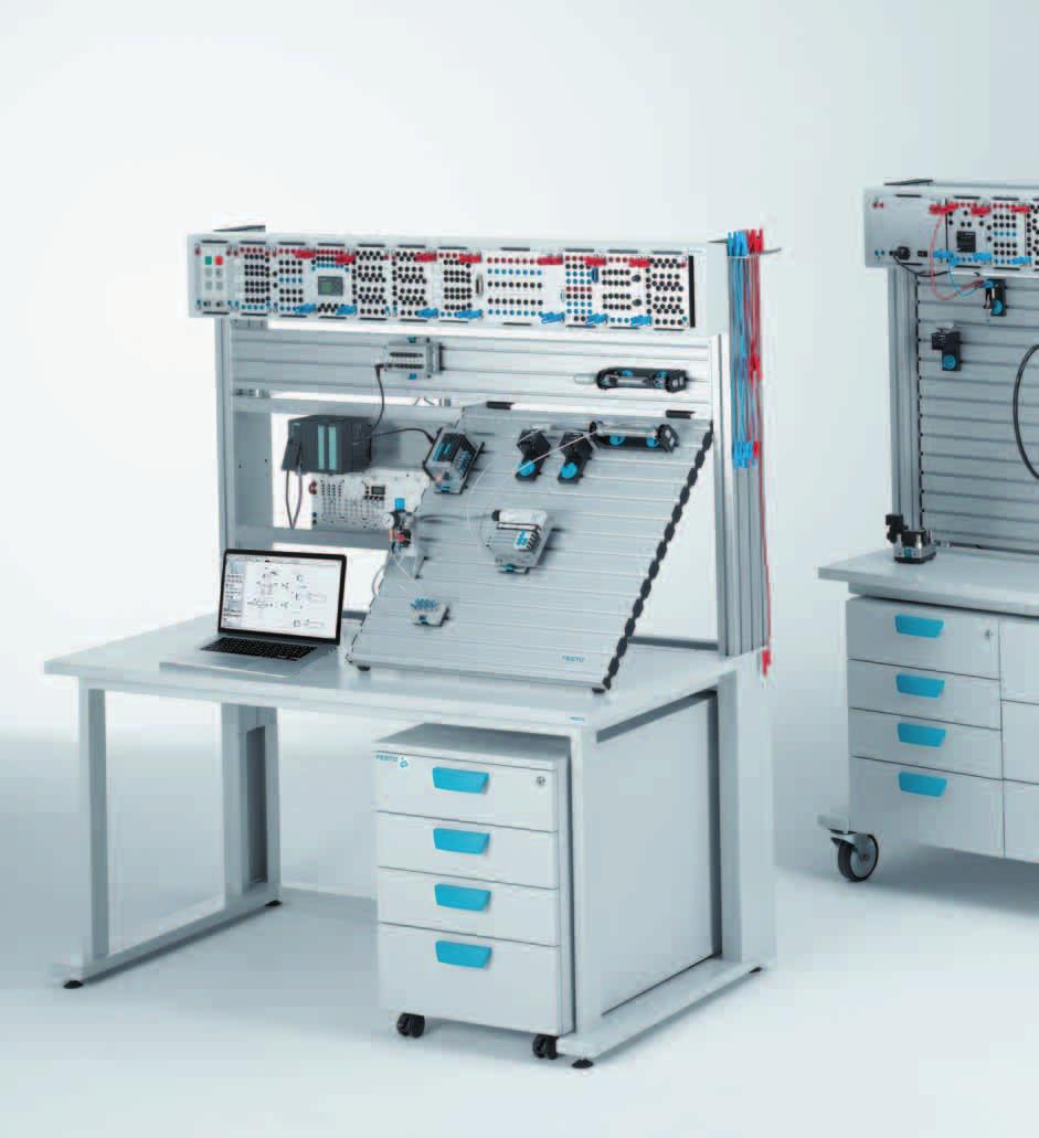
30 Workstation systems > Universal laboratory furniture > Learnline Learnline mobile More versatile than ever! Flexible and modular Learnline is of modular design and offers an almost unlimited range of configuration possibilities for your Learnline workstation. High mobility and optimum use of space Individual or group training workstations can be created with a minimum of effort wherever they are required. Transport through doors is also possible. This mobile workstation is designed in such a way as to permit several people to work simultaneously. This is further facilitated by the two integrated, fixed drawer units that ensure quick and easy access to the required components of the Learning System. Learnline Winner of international design awards 8 4-month Festo Didactic warranty


31 Workstation systems > Universal laboratory furniture > Learnline Optimum use of space The positioning of the storage plate means that the free space beside the fixed drawer units can be used for Systainer or other storage systems. The hydraulic power unit with single pump fits conveniently beside the 00 mm profile plate. Hydraulics for advanced trainees The double pump power unit fits neatly on the frame beside the fixed drawer units with no additional attachment required. The discharge measuring container also fits beside the 00 mm profile plate. Pneumatic and electrotechnical training The storage plate can hold up to two compressors. Further mounting frames for electronic components in A4 format, for example, can be used in addition to the 700 mm profile plate. Vertical or inclined? Choose the vertical profile plate if you want to use the worktop for books or laptops, for example. Or if the workstation is to be used from both sides, opt for the inclination unit with an additional profile plate to adapt the plate inclination to your requirements. The preferred types with price advantage. Flexibly expandable. (Overall dimensions W556 x D780 x H77) With 00 x 700 mm profile plate and ER frame 5908 With 700 x 700 mm profile plate and ER frame 5900 With x 700 x 700 mm profile plate and ER frame 5755 Worldwide at your fingertips. Find your contact person at: 9

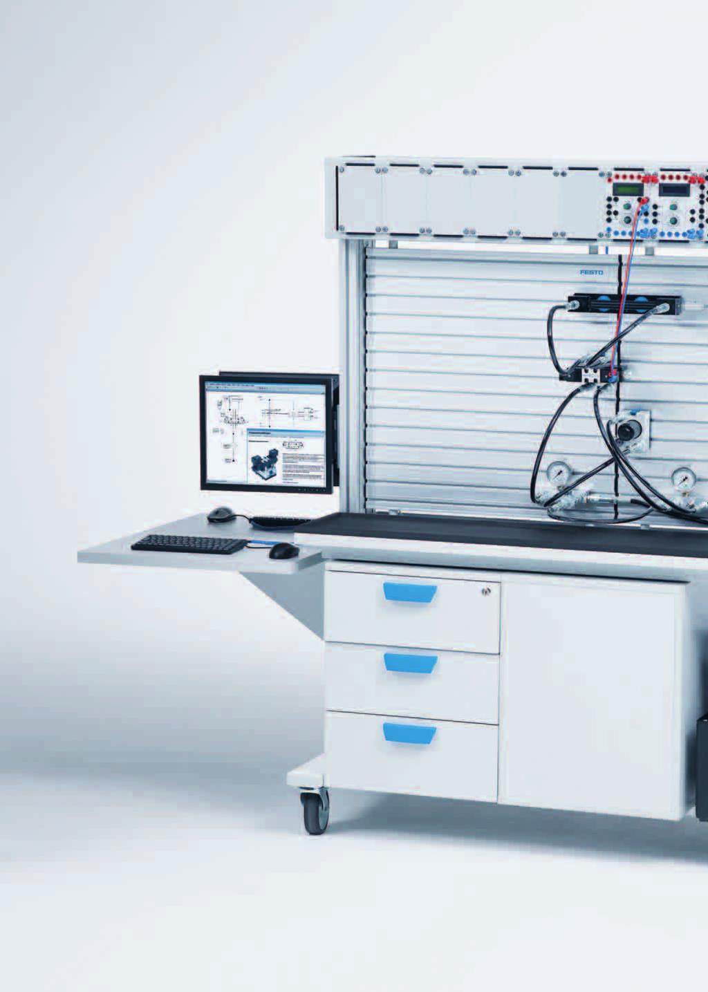
32 Workstation systems > Universal laboratory furniture > Learnline Stationary Learnline Ergonomic and flexible The stationary solution With the stationary workstation systems, Learnline combines the requirements for typical desk systems with high functionality. They provide ample desk space and legroom thanks to the roller container. The containers also ensure quick and easy access to any required components. Vertical or inclined? The sturdy profile plate is fastened to the stable profile of the angle a d- justment. The inclination of the slotted profile plate can be infinitely adjusted, all the way down to a horizontal position. The workstation arrangement thus always offers the best ergonomic position for any exercise. Learnline Winner of international design prices 0 4-month Festo Didactic warranty


 profile plate, additional mounting frames can be inserted for electronic components.")

33 Workstation systems > Universal laboratory furniture > Learnline Move up into another dimension: profile columns as set-up space Use the versatile profile columns as a set-up space, compatible with Quick- Fix, for equipment sets or for attaching additional components vertically. Additional components, for example cylinders with a 400 mm stroke, can be mounted on the angle adjustment profile. Optimum space utilization Thanks to the angle adjustment, the profile plate can be lowered into a horizontal position. Use the available space for A4 or ER mounting frames. Pneumatic and electrical training In addition to the 700 mm (7.5 ) profile plate, additional mounting frames can be inserted for electronic components. Ergonomic connections With the supply duct, all important interfaces are within reach. In addition to the electrical and pneumatic supplies, PC interfaces, such as USB, Ethernet, or serial interfaces, can also be integrated in the supply duct. The preferred types with price advantage. Flexibly expandable. (Overall dimensions W5 x D780 x H78) With 00 x 700 mm profile plate and ER frame 590 With 700 x 700 mm profile plate and ER frame 5905 Order no with supply duct On request Worldwide at your fingertips. Find your contact person at:
34 Workstation systems > Universal laboratory furniture > Learnline Your individual design Basic units Stable and with a high-quality coating, the basic worktables are guaranteed to fulfill your high requirements. Basic mobile unit With castors and wheel brakes. The high worktop ensures a comfortable working position when standing. The flexible design of this workstation makes it ideally suited to simultaneous use from both sides. W 556 x D 780 x H 85. Basic stationary unit The height of the worktop ensures a comfortable working position when seated. For holding a mounting frame for profile plate set-up. W 5 x D 780 x H 760. Basic mobile unit 558 Basic stationary unit Drawer units /4/5 Fixed drawer unit for installation in mobile workstations Drawer unit with fully-extending, lockable steel drawers with safety stop. Fronts can be labelled. Load 0 kg per drawer. External dimensions of body W 476 x D 788 x H 59, usable inner dimensions W 75 x D /7/8 Wheeled drawer unit for stationary workstations Wheeled drawer unit with fully extending, lockable steel drawers with safety stop. Fronts can be labelled. Load 0 kg per drawer. External dimensions body W 476 x D 788 x H 657, usable inner dimensions W 75 x D 700. All wheels freely movable, two wheels with lockable brake. 5 8 Fixed drawer unit for pneumatics (4 drawers) Fixed drawer unit for hydraulics ( drawers) Fixed drawer unit for mobile hydraulics ( drawers) Wheeled drawer unit for pneumatics (4 drawers) Wheeled drawer unit for hydraulics ( drawers) Wheeled drawer unit for mobile hydraulics ( drawers) month Festo Didactic warranty
35 Workstation systems > Universal laboratory furniture > Learnline Mounting frame/mounting sets Versatile profile columns form the core of the Learnline system. They are used to mount the profile plate frame, to attach components, or as an alternative mounting surface for your training components. For vertical mounting of the profile plate The profile plate support is mounted between the profile columns, the profile plate is securely screwed to the mounting frame and the frame structure. This makes the workstation extremely strong and resilient and means that the profile plate can be used from both sides. For inclined mounting of the profile plate The profile plate support can be mounted at any height between the two profile columns, ensuring workstation ergonomics tailored to your requirements. You can also place the components from the training package directly on the mounting frame, thereby freeing up additional workspace. Mounting frame/mounting sets for A4 mounting frame A4 mountings are mounted between the profile columns. Up to three rows of A4 mountings can be attached by means of two additional mounting sets for A4 mounting. When mounting profile plates, order one mounting set per profile plate. When mounting A4 units, order one mounting set for A4 mounting for each additional row. Mounting frame for vertical mounting of the profile plate Mounting set for vertical mounting of the profile plate Mounting frame for inclined mounting of the profile plate 590 Mounting set for inclined mounting of the profile plate 5975 Mounting frame for A4 mounting frame Mounting set for A4 mounting frame /5 Aluminum profile plates The anodized aluminum profile plate forms the basis for all training packages. All of the components fit securely and safely into the grooves on the profile plate. There are grooves on each side and, if required, both sides can be fitted with components. The grooves are compatible with the ITEM profile system. Grid dimensions: 50 mm (.97 ). For installation on tables we recommend the appropriate rubber feet (order no. 584) x 550 mm x 700 mm x 00 mm 594 Worldwide at your fingertips. Find your contact person at:
36 Workstation systems > Universal laboratory furniture > Learnline Your individual design 4 ER and DIN A4 mounting frames The mounting frames for the workstations are designed to hold a large number of exercise boards and ER units from the Learning System for Automation. This compatibility also extends to electrotechnical equipment in A4 format. It is thus possible to obtain a satisfactory solution to almost any specific task. / Mounting frame (500 mm wide) The frame mounted on the profile column is height-adjustable and holds up to ER/6 A4 units. One mounting frame can be attached to each side of the mobile workstation. /4 Mounting frame (700 mm wide) The small mounting frame permits the use of ER/A4 components to the direct left or right of a 700 mm broad profile plate. ER mounting frame (500 mm wide) 590 ER mounting frame (700 mm wide) 590 A4 mounting frame (500 mm wide) A4 mounting frame (700 mm wide) Oil spillage/protective mat Black, with rubber border. Protects the tabletop of the Learnline system and keeps it clean. x 5 mm 54 6 Storage plate Fits into the mobile frame, in addition to two drawer units, and offers installation space for two compressors (order no. 900) for example. W 748 x D 40 x H 0. Order no Table extension For easy attachment to the profile column of a mobile workstation. The height of the table can be adjusted to between 700 and 85 mm. The tabletop dimensions are W 780 x D 600. Order no month Festo Didactic warranty

37 Workstation systems > Universal laboratory furniture > Learnline Accessories Universal bracket Permits the mounting of up to two hydraulic power units with single pump, up to two hydraulic measuring containers, or holders for storing hoses. W 50 x D 75 x H 0. Order no Hose holder For up to 0 hydraulic hoses. Provides neat storage and protects hose couplings from ingress of dirt. W 66 x D 8 x H 80. Order no Cable guide For a set of laboratory cables. Ensures that cables are kept neatly and in order. W 50 x D 6 x H 6. Order no Monitor bracket, short Monitor bracket for TFT and LCD monitors with drill holes in accordance with the VESA standard (distance between holes 75 x 75 mm or 00 x 00 mm). Short swivel arm for minimum distance to the mounting surface (approx. 8 cm) For mounting on Learnline mounting frames or fastening to a wall Rotatable up to 80, tiltable up to 45 Supplied complete with mounting material Maximum load capacity kg Order no /7/8 Protective grounding for workbenches The products serve as protective grounding for workbenches as per the VDE 000 standard. This is achieved by connecting accessible, conductive parts to each other by means of equipotential bonding conductors and by connecting all this to the PE conductor of the power supply. 6 Grounding kit A grounding kit is required for connecting all conductive parts of one to two workbenches. The connector for the PE conductor of the power supply is included. Order no Connection kit A connection kit is required for connecting a workbench to the PE conductor of the power supply. Order no T connector for PE conductors A T connector lets you combine up to three PE conductors for connection to the power supply. Order no Monitor bracket, long Monitor bracket for TFT and LCD monitors with drill holes in accordance with the VESA standard (distance between holes 75 x 75 mm or 00 x 00 mm) Long, telescopic, articulated arm for a large swivel angle Distance from mounting surface (approx. 8 8 cm) For mounting on Learnline mounting frames or fastening to a wall Rotatable up to 80, tiltable up to 45 Supplied complete with mounting material Maximum load capacity 5 kg Order no Worldwide at your fingertips. Find your contact person at: 5


: 0 x 55 x 980 mm Accepts up to four profile plates of size 50 x 00 mm (order no. 660) or two profile plates 700 x 00 mm (order no. 594).")
38 Workstation systems > Universal laboratory furniture > Learntop Learntop The low-cost desktop mounting system The low-cost introduction to the world of training packages from Festo Didactic: Enjoy the advantages of the profile plate and the ER mounting frame when carrying out your pneumatic, hydraulic, sensor, or PLC training. The devices can be clearly arranged and ensure an ergonomic working position at your existing work tables and benches. Mounting parts and instructions for mounting the profile plates are included. It is recommended that Learntop be fastened to the table for security reasons. Learntop-S The versatile equipment holder for all technologies. Mobile: Can be simply set up on an existing work table/bench. Versatile: Can be used from both sides. Ergonomic: The angled profile plate enables components to be easily assembled. Dimensions (W x H x D): 0 x 55 x 980 mm Accepts up to four profile plates of size 50 x 00 mm (order no. 660) or two profile plates 700 x 00 mm (order no. 594). Accepts up to two profile plates of size 50 x 00 mm (order no. 660) and two slotted mounting plates for Learntop-S for mounting Quick-Fix clamping components, one on each side. Profile plates not included. Order no Mobile worktable for Learntop-S Drawer unit with eight fully extending drawers. Load up to 0 kg per drawer Storage space with lockable sliding doors Steel tub table top Dimensions (W x H x D): 8 x 90 x 778 mm Table top height: 90 mm Order no month Festo Didactic warranty


39 Workstation systems > Universal laboratory furniture > Learntop Learntop-S Accessories Aluminum profile plate The anodized aluminum profile plate forms the basis for all training packages. All of the components fit securely and safely into the grooves on the profile plate. There are grooves on each side and, if required, both sides can be fitted with components. The grooves are compatible with the ITEM profile system. Grid dimensions: 50 mm. For installation on tables we recommend the appropriate rubber feet (order no. 584). 4 Cable guide For a set of laboratory cables. Ensures that cables are kept neatly and in order. W 50 x D 6 x H 6. Order no Hose holder For up to 0 hydraulic hoses. Provides neat storage and protects hose couplings from ingress of dirt. W 66 x D 8 x H 80. Order no Steel tub base for Learntop-S Order no Size 50 x 00 mm supplied without side caps (H x W). 50 x 00 mm x 00 mm 594 Perforated work surface For Lab-Volt Series Pneumatics/Hydraulics Training System, 700 mm x 00 mm for Learntop-S. (Only compatible with Learntop-S) Order no Slotted mounting plate For mounting Quick-Fix clamping components. Must be used together with an Aluminum profile plate 50 mm x 00 mm (order no. 660) to hold Quick-Fix screw components as well. (Only compatible with Learntop-S order no. 8067) Order no Mounting kit for hydraulic cylinder with weight To be mounted on Learnline with a vertical or horizontal profile plate (alternatively for mounting on the Learnline profile column) or Learntop-S with an inclined profile plate. With this mounting kit, the pulling and pushing load of the basic hydraulics packages, which comprise the cylinder (order no. 5857) and weight (order no. 597), can be achieved. The cover (order no. 597) must be used for safety reasons. Learntop-S, inclined profile plate Order no Worldwide at your fingertips. Find your contact person at: 7


40 Workstation systems > Universal laboratory furniture > Learntop Learntop-A/Learntop-L The low-cost desktop mounting system The low-cost introduction to the world of training packages from Festo Didactic: Enjoy the advantages of the profile plate and the ER mounting frame when carrying out your pneumatic, hydraulic, sensor, or PLC training. The devices can be clearly arranged and ensure an ergonomic working position at your existing work tables and benches. Mounting parts and instructions for mounting the profile plates are included. It is recommended that Learntop be fastened to the table for security reasons. Learntop-A Equipment holder for use on one side of the workstation. Inclined profile plate allows ergonomic arrangement of components. Not suitable for hydraulic training. Can hold up to two profile plates of size 50 x 00 mm (order no. 660) or one profile plate of size 700 x 00 mm (order no. 594). Profile plates not included. Order no Learntop-L Equipment holder for use on one side of a workstation; for profile plates of size 700 x 00 mm (order no. 594). For horizontal profile plate configurations. Not suitable for hydraulic training. Profile plates not included. Order no month Festo Didactic warranty

. 50 x 00 mm 660 700 x 00 mm 594 Slotted mounting plate All components with the Quick-Fix mounting system can be mounted on slotted mounting plates.")

41 Workstation systems > Universal laboratory furniture > Learntop Learntop-A/Learntop-L Accessories Aluminum profile plate The anodized aluminum profile plate forms the basis for all training packages. All of the components fit securely and safely into the grooves on the profile plate. There are grooves on each side and, if required, both sides can be fitted with components. The grooves are compatible with the ITEM profile system. Grid dimensions: 50 mm. For installation on tables we recommend the appropriate rubber feet (order no. 584). Size 50 x 00 mm supplied without side caps (H x W). 50 x 00 mm x 00 mm 594 Slotted mounting plate All components with the Quick-Fix mounting system can be mounted on slotted mounting plates. The slotted mounting plates are fitted with elastic buffers and can be used horizontally on a table top. Order no. 59 can also be inserted in conventional A4 mounting frames. The slotted mounting plates are not intended for use with actuators. (overall dimensions B x H) 694 x 97 mm x 550 mm Rubber feet For non-slip, protective mounting of profile plates on tabletops of any type. Set (four pieces). Order no Mounting kit for hydraulic cylinder with weight To be mounted on Learnline with a vertical or horizontal profile plate (alternatively for mounting on the Learnline profile column) or Learntop-S with an inclined profile plate. With this mounting kit, the pulling and pushing load of the basic hydraulics packages, which comprise the cylinder (order no. 5857) and weight (order no. 597), can be achieved. The cover (order no. 597) must be used for safety reasons (similar to illustration). 5 Plug-in adapter set The plug-in adapter set can be used to mount the ER units directly on the blue plug-in board or on the aluminium profile plate. One set is required to mount one unit. Order no A4 ER mounting frame The ER mounting plate can be installed in any A4 mounting frame. A cut-out permits installation of two large or four small Festo Didactic ER units (H x W). 97 x 500 mm Learnline, vertical profile plate Order no. 558 Learnline, horizontal profile plate Order no. 95 Worldwide at your fingertips. Find your contact person at: 9

42 40 Pneumatic/Hydraulic training packages

43 Overview Pneumatics /Hydraulics training packages...4 Pneumatics System description...46 Pneumatics...48 Electropneumatics...56 Measurement and control...64 Drives...66 Vacuum...68 Sensors...70 Safety...7 BIBB pneumatics...74 BIBB electropneumatics...76 Closed-loop pneumatics...77 Energy-efficient compressed air management...78 Sensors /PLC...80 Hydraulics System description...8 Hydraulics...84 Electrohydraulics...9 Measurement and control...00 Proportional hydraulics...0 Closed-loop hydraulics...06 BIBB hydraulics...08 Mobile hydraulics
44 Pneumatic/Hydraulic training packages > Overview Pneumatic training packages Overview and structure TP 50 Safety in pneumatic systems TP 40 Sensors in pneumatics TP 0 Vacuum technology Basic/ precondition Basic-level training packages provide a foundation that will introduce participants to the topic. The components and training content of the basic-level packages must be completed before the participants can move to the advanced level. Advanced/ supplement Advanced-level training packages allow participants to develop more in-depth knowledge in a number of specialist areas, depending entirely on their own needs. Supplementary equipment sets are an efficient way to add additional basic levels to any basic-level training package. TP 0 Drives in pneumatics TP 0 Measurement and Control TP 0 Pneumatics Advanced level TP 0 Electropneumatics Advanced level TP 0 Pneumatics Basic level TP 0 Electropneumatics Basic level TP Closed-loop pneumatics Basic level TP Sensors for object detection TP 0 America Pneumatics Basic level TP 0 America Electropneumatics Basic level TP 0+ Pneumatics Troubleshooting TP 0 Electropneumatics PLC s Virtual control using FluidSIM / EasyPort USB Control using LOGO! / Soft Comfort 4 4-month Festo Didactic warranty
45 Pneumatics/Hydraulics training packages > Overview Hydraulic training packages Overview and structure Basic/ precondition Advanced/ supplement Basic-level training packages provide a foundation that will introduce participants to the topic. The components and training content of the basic-level packages must be completed before the participants can move to the advanced level. Advanced-level training packages allow participants to develop more in-depth knowledge in a number of specialist areas, depending entirely on their own needs. Supplementary equipment sets are an efficient way to add additional basic levels to any basic-level training package. TP 60 Measurement and Control TP 5 Closed-loop hydraulics Basic level TP 80 Mobile hydraulics Working hydraulics II (Load-sensing) TP 50 Hydraulics Advanced level TP 60 Electrohydraulics Advanced level TP 70 Advanced proportional hydraulics training TP 80 Mobile hydraulics Hydrostatic steering system TP 50 Hydraulics Basic level TP 60 Electrohydraulics Basic level TP 70 Basic proportional hydraulics training TP 80 Mobile hydraulics Working hydraulics I TP 50 America Hydraulics Basic level TP 60 America Electrohydraulics Basic level TP 80 Pneumatics/Hydraulics Measurement TP 50+ Hydraulics Troubleshooting Virtual control using FluidSIM / EasyPort USB Control using LOGO! / Soft Comfort 4

46 Pneumatic/Hydraulic training packages > Overview Transition from LabVolt... Pneumatic and Hydraulic training packages Hydraulics Training System Pneumatics Training System Sensors Sensors 6085 Advanced Servo Control of Hydraulic System Servo Control of Pneumatic System Add-On to Electrical Control Add-On to Electrical Control Basic PLC 608 Electrical Control Electrical Control 608- Add-On to Fundamentals Add-On to Fundamentals Troubleshooting Hydraulic Circuits 6080-F Fundamentals Fundamentals 608- Troubleshooting Pneumatics Circuits 608-F Add-On to Fundamentals Basic System Basic System Add-On to Fundamentals 44 4-month Festo Didactic warranty

47 Pneumatics/Hydraulics training packages > Overview... to Festo Didactic Series Hydraulics Training Packages Pneumatics Training Packages Sensors for object detection TP Closed-loop Hydraulics TP 5 Closed-loop Pneumatics TP Control Kit FluidSIM EasyPort USB Control Kit LOGO! Soft Comfort Electrohydraulics TP 60 America Electropneumatics TP 0 America Troubleshooting TP 50+ Basic Hydraulics TP 50 America Basic Pneumatics TP 0 America Troubleshooting TP


48 Pneumatic training packages > System description Pneumatic training packages Innovative and practical, right down to the smallest details Modular for flexible expansion Festo Didactic s training packages are modular in structure. For example, you could start with the basic level of electropneumatics and then move onto the advanced level, or start with the subject of electrohydraulics the choice is yours. You d like to explore a particular specialized topic? All equipment set components can also be ordered separately, so you can turn your own ideas into reality. Position it clamp it done! With the Quick-Fix mounting system, you can mount all components easily and securely on the profile plate and the profile column of a Learnline workstation. The electrical units are clamped into the ER frame and sequenced individually. The profile slots on the workstations are the same for all pneumatic, hydraulic and electrical units a single investment, with double the functionality. Everything where you want it systematic storage Most equipment sets are delivered in practical, Systainer-compatible equipment trays. This equipment tray fits in the drawers of the workstations. The large pictogram on the components, designed in accordance with the latest standards, provides clear instructions for connecting the components and ensures short preparation and follow-up times. When dismantling circuits, you can quickly and easily locate where the component goes in the equipment tray. Connect it power! No compromise on safety: all electrical components and units are connected with 4 mm safety sockets or safety plugs. The pneumatic power is supplied by the connection of highly flexible plastic tubing to the Quick Star (QS) push-in fitting. The system therefore requires virtually no consumables or tools month Festo Didactic warranty


49 Pneumatic training packages > System description Didactic plus The workbooks accompanying the training packages contain project-oriented exercises of increasing complexity. There are also positional sketches, illustrations, videos, animations, and cross-sectional drawings, which explain how things look in the real world. For a complete and expert treatment of the topic of pneumatics, the training also covers basic physics, technical calculations, safety, economic efficiency, analytical fault-finding, and professional documentation. Practical basic and specialized training using industrial components provides the confidence to apply the acquired knowledge in the workplace. The components are specially selected for the exercises in the workbook. Note: nearly all pneumatic and electrical connections are located on the easily accessible upper side of the components. Your choice of training environment User-friendly training environments for specific topic areas: Self-study phases with the training programs Designing and documentation with FluidSIM Hands-on experimentation with the training packages and the exercises in the workbooks Functional testing and optimization with measurement technology and FluidLab Advanced courses made easy New developments and trends in fluid engineering can be incorporated directly into our learning systems. New control systems can be integrated into the learning system using the EduTrainer concept. Basic packages can be easily expanded to include the subjects Pneumatics measurement and control TP 0 or the new Vacuum technology TP 0. TP 0 Vacuum technology Manipulating workpieces with suction grippers has become an indispensable part of handling technology. It offers advantages, such as the simple configuration of suction grippers and gentle handling of workpieces, while also enabling rapid cycle times, and the capital outlay required is comparatively low. The training package TP 0 expands the contents of TP 0 to include the key area of vacuum technology. TP 50 Safety in pneumatic systems Function, efficiency, and above all safety determine the success of plant machinery and automated systems. New directives and laws require intelligent solutions and raise the level of professional skills required. The systematic optimization of a simple pneumatic system helps to identify hazards in pneumatic processes. The appropriate actions to reduce the risk can be implemented in a professional manner. 47
50 Pneumatic training packages > Equipment sets > Pneumatics Equipment set TP 0 Basic level Basic pneumatics training Pneumatics, Basic level The fully revised classic Further enhanced and updated according to the lessons learned from over,000 seminars on pneumatics. Brand-new components enable you to teach tomorrow s industrial standard today. The workbook contains a series of progressively complex project exercises based on actual industrial applications, an enhanced section on fundamentals, and a multimedia CD-ROM. The number of components and the design are specially tailored to the projects contained in the workbook so that the main fundamentals can be imparted with little outlay. Delivered in practical, Systainer-compatible equipment trays. Training aims Structure, function, and application of single-acting and double-acting cylinders Calculating basic parameters Direct and indirect actuation Application and function of / and 5/-way valves Methods of actuation of directional control valves Analyzing circuits Options for pressure measurement Pressure-dependent control systems Distinguishing flow control methods and applying them appropriately Explaining and building latching circuits Logic operations: explaining and implementing AND/OR/NOT operations Combining logic operations Function and application of limit switches Time delay valves Realizing oscillating movement Economic considerations of using pneumatic components Performance through close proximity For optimum performance, switches and valves should be mounted as close to the actuator as possible. With the addition of new components, you can now apply the same principle when designing your circuits. This approach also provides you with an easy way of demonstrating the performance of a one-way flow control valve. You can even record the measured values and analyze the results, for example, using the TP 0! The next generation of valves The new generation of valves allows the operation of various pressure zones so nothing stands in the way of an efficient use of energy. In addition, the position of connection was optimized so that differences between the circuit symbol and the valve can be avoided. Pneumatic timer The easy-to-read pneumatic timer can be precisely adjusted. Pressure changes do not alter the set delay time. Pneumatics at its best month Festo Didactic warranty
51 -SJ -KH -QM -BG -PG -RZ 4 -MM 4 5 -BG -SJ -PG -RZ Workbook TP 0 With CD-ROM Festo Didactic en Pneumatic training packages > Equipment sets > Pneumatics Complete equipment set TP 0 in equipment tray The most important components at a glance : x /-way valve with pushbutton actuator, normally closed 5860 x /-way valve with pushbutton actuator, normally open 586 x 5/-way valve with selector switch x /-way valve with selector switch, normally closed x /-way roller lever valve, normally closed x Proximity sensor, pneumatic, with cylinder attachment x Pneumatic timer, normally closed x Pressure sequence valve x /-way valve, pneumatically actuated at one end x 5/-way valve, pneumatically actuated at one end x 5/-way double pilot valve, pneumatically actuated at both ends 5760 x Shuttle valve (OR) 5977 x Dual-pressure valve (AND) x Quick-exhaust valve x One-way flow control valve x Single-acting cylinder x Double-acting cylinder x Start-up valve with filter control valve x Pressure regulator valve with gauge x Pressure gauge 5865 x Manifold 5896 x Plastic tubing, 4 x 0.75 silver 0 m Accessories, also order: Aluminum profile plate Page 9 Compressor Page Also order: Workbook Pneumatics Basic level The workbook includes: Sample solutions Training notes Multimedia CD-ROM with graphics, photos of industrial applications, animations, and FluidSIM circuit diagrams Exercise sheets for trainees Campus license ( Page 9): de en es fr Nineteen project-orientated exercises, increasing in complexity and suitable for equipment set TP 0, are the ideal introduction to pneumatics. Real problem descriptions with positional sketch, concrete project tasks, and detailed aids for professional implementation provide the ideal preparation for the real-life industrial environment. Supplementary media Design and simulation using FluidSIM WBT Pneumatics Textbook: Basic principles of pneumatics and electropneumatics Cutaway model case 49

52 Pneumatic training packages > Equipment sets > Pneumatics Equipment set TP 0 + Advanced level Systematic troubleshooting Realistic Equipment set TP 0+ from Festo Didactic is an extension to equipment set TP 0. TP 0+ contains components with specified, realistic defects. It enables pneumatic circuits to be constructed with the TP 0 and individual components to be replaced by defective ones. Using our experience in industrial environments, we were able to define typical error patterns for pneumatic systems and adapt them to the components contained in equipment set TP 0+. Professional Systematic troubleshooting and professional error elimination are an essential part of everyday operations in many jobs in the fields of mechanics, mechatronics, and electrical engineering. In order to acquire skills in this area via a structured, yet safe, procedure, it is important that systematic troubleshooting is both learned and practiced. Keys to this are: Understanding circuits and discerning any non-conformities Delimiting/precluding fault areas Locating and rectifying faults Cylinder with worn piston seal One example of a defective component is a double-acting cylinder with a worn piston seal. This defect may be due to damage to the piston rod or dirt entering the system. The defect leads to the cylinder leaking via the piston. Conspicuous symptoms result in compressed air losses and a lower cylinder force. Pressure sensors or force sensors may not switch, which can lead to interruptions in operation cycles or process safety being put at risk. Clogged filters Another example is a clogged filter in the on-off valve with pressure regulator (service unit). Filters are used to protect upstream components from contamination. If a large amount of contamination enters the system via the compressor s intake tract, these filters can become clogged. This applies in particular to micro filters. The defect results in increased flow resistance, and consequently, restricted flow, which in turn has a throttling effect. The inspection and replacement of such filters is a routine maintenance task in industry. This procedure assumes specialist knowledge, such as modes of operation of individual components and their system limits month Festo Didactic warranty


53 Pneumatic training packages > Equipment sets > Pneumatics Complete equipment set TP 0+ in equipment tray The most important components at a glance : x Double-acting cylinder, defective x Pressure gauge, defective x Filter sleeves for on-off valve with filter regulator, clogged x /-way valve with pushbutton actuator, normally closed, defective x 5/-way bistable valve, defective x 5/-way valve, mid-position pressurized x Flow control valve x Silencer M5, clogged Accessories, also order: Aluminum profile plate Page 9 Compressor Page Requirements Building on Basic Level Pneumatics, the Advanced Level contains eight components appropriate for equipment set TP 0. The possible troubleshooting tasks are aimed at all jobs involving maintenance and repair activities. Special measuring equipment is not required since all symptoms are observable. However, error patterns can also be quantified using measuring equipment such as a flowmeter. Study materials A description is included for each defective component describing both its function and the fault. A flow chart, which guides learners systematically from observation of the symptom to the repair task, is also included. Supplementary media Design and simulation using FluidSIM WBT: Pneumatics Textbook: Basic principles of pneumatics and electropneumatics Cutaway model case From vocational educational to industrial reality 5
54 Pneumatic training packages > Equipment sets > Pneumatics Equipment set TP 0 Advanced level Advanced pneumatics training Develop the training aims from TP 0 and consolidate your knowledge. Fully revised: The new workbook contains a series of progressively complex project exercises based on actual industrial applications and an enhanced section on fundamentals. It also includes a multimedia CD- ROM. The foundation for competent training. Place your order now! The number of components and the design are specially tailored to the projects contained in the workbook so that the main training aims can be achieved with little outlay. Delivered in practical, Systainer-compatible equipment trays. Components from the equipment set TP 0 are required to carry out the projects. Training aims Binary reducing stages End positions without limit switches Latching circuits Converting 5/-way valves Function of a back pressure end stop Basic stepper control (continuous cycle) Stepper control with operating modes or idle step Setting and coordinating time delays Variable step repetition using a predetermining counter Input circuit with self-latching loop and auxiliary functions Evaluating and using sensors for material sensing Realizing stepper control with protected pilot air and auxiliary functions Proximity sensors in the end positions and in the partial stroke range Combined use of quick exhaust valves and pressure regulators Inversion of a timer signal Varying end-position cushioning Using and adjusting different sensor types Performance through close proximity For optimum performance, switches and valves should be mounted as close to the actuator as possible. With new components that can be plugged in directly, you can now apply the same principle when designing your circuits. This approach also provides you with an easy way of demonstrating the features of a oneway flow control valve. You can even record the measured values and analyze the results, for example, using the new TP 0! Lever valves All of the lever valves contained in the training packages 0 and 0 are equipped with a pilot control, which means they require a low actuating force and deliver high reliability. 5 4-month Festo Didactic warranty
55 Workbook TP 0 With CD-ROM Festo Didactic EN Pneumatic training packages > Equipment sets > Pneumatics Complete equipment set TP 0 in equipment tray 5407 The most important components at a glance : x /-way valve with pushbutton actuator, normally closed 5860 x /-way valve with mushroom-head emergency switch, normally open 5864 x /-way roller lever valve with idle return, normally closed x Back pressure valve x /-way valve, pneumatically actuated at one end x 5/-way double pilot valve, pneumatically actuated at both ends x Plastic tubing, 4 x 0.75 silver 0 m x Shuttle valve (OR) x Dual-pressure valve (AND) x Pneumatic timer, normally open x Pneumatic preset counter 5877 x Stepper module 5886 x One-way flow control valve x Non-return valve, delockable x Double-acting cylinder Accessories, also order: Aluminum profile plate Page 9 Compressor Page Also order: Workbook Pneumatics Advanced level The workbook includes: Sample solutions Training notes Multimedia CD-ROM with graphics, photos of industrial applications, animations, and FluidSIM circuit diagrams Exercise sheets for trainees Campus license ( Page 9): de en es fr As a continuation of the basic level for pneumatics, the advanced level includes ten additional, challenging tasks which are suitable for the TP 0 equipment set. The documents are targeted at experienced pneumatics technicians. New features of this revised and updated edition include revised exercise sheets for practical use during instruction. Supplementary media Design and simulation using FluidSIM WBT Pneumatics Textbook: Basic principles of pneumatics and electropneumatics Cutaway model case 5

56 Pneumatic training packages > Equipment sets > Pneumatics Pneumatics Basic level TP 0 America Equipment set The Lab-Volt Pneumatics Fundamentals successor The Lab-Volt Fluid Power System has been re-engineered and transferred to Festo Didactic s Training Packages series. TP 0 America now combines the proven learning approach through object-oriented courseware from Lab-Volt with the project-orientation from Festo Didactic. TP 0 America is the basic level for education in pneumatics and a prerequisite for TP 0 America, Electropneumatics Basic Level. TP 0 and TP 0 America support vocational training institutes in their mission to educate skilled, resourceful technicians and engineers, as required by the local industry. Education concept for future professionals The course curriculum accompanying the learning system is designed to follow industry standards. First, at the beginning of each exercise, meaningful objectives are clearly stated. Then, the theory to attain these objectives is laid out extensively, with an emphasis on component description. Next comes the laboratory procedure itself. In this section, students follow precise and safe working instructions designed to teach them the practical principles related to the stated objectives. Throughout the laboratory procedure, questions and remarks ensure that students analyze and comprehend the results they obtain. Finally, review questions ascertain the degree of comprehension of students relative to the topics discussed in the exercise. Safe and sound system The design of the system components ensures a high level of inherent safety. The On-Off Valve with Filter Regulator can be locked with a padlock to avoid unauthorized access to the compressed air supply. The Spring Load for Cylinders comes with a safety cover to prevent potential hazards when high forces are involved. The Air Motor is protected by a safety cover that does not compromise speed measurement capabilities. Work instructions and safety precautions are provided to students as required when working with pneumatic, electrical, and mechanical setups. Training aims TP 0 America Introduction to Pneumatics Familiarization with the Training System Introduction to Pneumatics Air Conditioning and Distributing Equipment Basic Physical Concepts Pressure vs. Force Relationship Pressure vs. Volume Relationship Pressure Drop vs. Flow Relationship Vacuum Generation Basic Controls of Cylinders Directional Control Valves Direction and Speed Control of Cylinders Indirect Control Using Pilot-Operated Valves Basic Controls of Pneumatic Motor Pneumatic Motor Circuits Pneumatic Motor Performance 54 4-month Festo Didactic warranty
57 Festo Didactic en Pneumatic training packages > Equipment sets > Pneumatics Complete equipment set TP 0 America in equipment tray The most important components at a glance : x Lockable on-off valve with filter regulator x Pressure gauge 5865 x One-way flow control valve x /-Way-Panel mounted with pushbutton actuator, normally closed x /-Way- Panel mounted Valve with pushbutton actuator, normally open x 5/-way double pilot valve, pneumatically actuated at both ends x Single-acting cylinder x Double-acting cylinder, smooth running x Double-acting cylinder x Air pressure reservoir, 0.4 l 59 x Vacuum generator, type H 5758 x Vacuum gauge 5704 x Suction gripper 0 SN x Plastic tubing x Manifold x Contact tachometer x Spring load for cylinders, pneumatic x Compressed air motor x Air Bearing x Flow indicator with float, pneumatic x Pneumatic resistance, long x Pneumatic resistance, short x Plastic tubing Accessories, also order: Workstations Page 9 Compressor and accessories Page Also order: Courseware TP 0 America Pneumatics Basic Level Detailed procedure descriptions with pneumatic diagrams, thorough analysis, troubleshooting exercises, and comprehensive theory coverage provide the ideal preparation for the real-life industrial environment Campus license ( Page 9): en The Campus License consists of an Instructor Guide and a Student Manual. In the courseware, exercises progressively increase in complexity, providing an ideal introduction to pneumatics. 55

58 4 -QM -MB -RZ 4 5 -MM +4 V 4 -SF -KF 4 A -KF -MB A 0V RZ Workbook TP 0 With CD-ROM Festo Didactic en Pneumatic training packages > Equipment sets > Electropneumatics Equipment set TP 0 Basic level Basic electropneumatics training Electropneumatics, Basic level. The most important basic principles in one compact book. Top solenoid valves for training Easy connection of the solenoid coils via 4 mm safety sockets with LED indicator for actuation. The manual override latches and allows very easy error simulation. The port pattern is as per the current symbols to DIN ISO 9. The newest valve technology is compact, sturdy, and inexpensive with the Didactic-Plus, and of course comes with the reliable Quick-Fix mounting system. Electronic proximity sensors compatible and reliable These proximity sensors are based on the same slot mounting system as the pneumatic proximity sensors in TP 0. We opted for short circuit-proof, electronic proximity sensors due to their long service life in training applications. Logic programming? That s logical. The basic principles are established with relay control systems and the new supplementary equipment sets Controllers for fluid engineering are used according to individual requirements. Training aims Structure, function, and application of single-acting and double-acting cylinders Calculating basic parameters Direct and indirect actuation Application and function of / and 5/-way solenoid valves Analyzing circuits Options for pressure measurement Pressure-dependent control systems Latching circuits Logic operations: AND/OR/NOT Combining logic operations Function and application of limit switches Time-delay valves End-position monitoring using electronic proximity sensors Realizing oscillating movement Economic considerations of using pneumatic components Troubleshooting simple electropneumatic circuits The workbook contains a series of progressively complex project exercises based on actual industrial applications, an enhanced section on fundamentals, and a multimedia CD- ROM. The foundation for competent training. Place your order now! The number and the design of components are specially tailored to the projects contained in the workbook so that the main training aims can be achieved with little outlay. Delivered in practical, Systainer-compatible equipment trays. Also order: Workbook Electropneumatics Basic level Campus license ( Page 9): de en es fr Supplementary media FluidSIM Pneumatics WBT Electropneumatics Textbook: Basic principles of pneumatics and electropneumatics Transparency set, Electropneumatics 56 4-month Festo Didactic warranty
59 Pneumatic training packages > Equipment sets > Electropneumatics Complete equipment set TP 0 in equipment tray 5407 The most important components at a glance: x Signal input, electrical 64 x Relay, three-fold 64 x Limit switch, electrical, left-actuated 8 4 x Limit switch, electrical, right-actuated x Proximity sensor, optical, M x Proximity sensor, electronic, with cylinder mounting x x /-way solenoid valve with LED, normally closed x 5/-way solenoid valve with LED x 5/-way double solenoid valve with LED x Pressure sensor with display x One-way flow control valve 9967 x Single-acting cylinder 5887 x Double-acting cylinder x Start-up valve with filter control valve x Manifold x Plastic tubing, 4 x 0.75 silver 0 m Accessories, also order: Aluminum profile plate Page 9 Compressor Page 4 Tabletop power supply unit Power supply unit for mounting frame Page 55 4 mm Safety laboratory cables Page Supplementary equipment set to upgrade from Pneumatics, Basic level TP 0 to Electropneumatics, Basic level TP 0 Supplements the Pneumatics, Basic level TP 0 equipment set to form a complete Electropneumatics, Basic level TP 0 equipment set. 6 Recommended training media and accessories: See TP 0 Complete supplementary equipment set TP 0 TP 0 in equipment tray The most important components at a glance: x Signal input, electrical 64 x Relay, three-fold 64 x Limit switch, electrical, left-actuated 8 4 x Limit switch, electrical, right-actuated x Proximity sensor, optical, M x Proximity sensor, electronic, with cylinder mounting x x /-way solenoid valve with LED, normally closed x 5/-way solenoid valve with LED x 5/-way double solenoid valve with LED x Pressure sensor with display x One-way flow control valve 9967 x Double-acting cylinder
60 Pneumatic training packages > Equipment sets > Electropneumatics Equipment set TP 0 Programmable logic controllers Complete equipment set TP The most important components at a glance: x Signal input, electrical 64 x Indicator unit and distributor, electrical 644 x Proximity sensor, inductive, M x Proximity sensor, capacitive, M x Proximity sensor, optical, M x Proximity sensor, electronic, with cylinder mounting x 5/-way solenoid valve with LED x 5/-way double solenoid valve with LED x Single-acting cylinder x Double-acting cylinder 5888 x Start-up valve with filter control valve x Manifold 5896 x Plastic tubing, 4 x 0.75 silver 0 m Recommended accessories: Aluminum profile plate Page 9 Universal connection unit, digital (SysLink) 6 Tabletop power supply unit Power supply unit for mounting frame Page 55 4 mm Safety laboratory cables Page 55 EduTrainer Supplementary equipment set from TP 0 to TP 0 Supplements the Electropneumatics basic level equipment set, TP 0, to form a complete Programmable Logic Controllers equipment set, TP 0. Complete supplementary equipment set TP 0 TP The most important components at a glance: x Proximity sensor, inductive, M x Proximity sensor, capacitive, M x Proximity sensor, electronic, with cylinder mounting 4475 For additional controllers suitable for your requirements see: Keyword EduTrainer Compact Training aims Benefits of the PLC compared to conventional solutions such as electrical, electropneumatic, or electrohydraulic solutions Functions of system components of a PLC Commissioning a PLC Application criteria for mechanical, optical, capacitive, and inductive proximity sensors Sequence control and parallel logic Systematic programming of a PLC in accordance with international standard IEC - IEC - programming languages: Function Block Diagram, Ladder Diagram, Statement List, Structured Text, and Sequence Language A PLC (Festo FC4, SIMATIC S7-00 or Allen Bradley) is required to carry out the tasks. Connection with universal connection unit and I/O data cable (SysLink) or with 4 mm safety connectors. I/O modules can be connected via 4 mm safety connectors. Also order: Workbook Programmable Logic Controllers, Basic level Campus license ( Page 9): de 9 en 94 es 9447 Recommended training media Textbook: Programmable Logic Controllers, Basic level 58 4-month Festo Didactic warranty
61 Pneumatic training packages > Equipment sets > Electropneumatics Supplementary equipment sets Controllers for electropneumatics Supplementary equipment set Controlling using FluidSIM / EasyPort USB With this package, the FluidSIM software can be used to control training packages. FluidSIM controls via EasyPort USB and processes the inputs and outputs connected to the universal connection unit according to their programming, e.g., using the digital module contained in FluidSIM. The Controlling using FluidSIM package contains everything you need to control training packages TP 0 and TP 60. FluidSIM Pneumatics is required for TP 0 and FluidSIM Hydraulics for TP 60. A set of brief instructions provides information on the individual steps. The sample solutions are included on a data storage medium as FluidSIM CT programs. 4 5 Complete supplementary equipment set Controlling using FluidSIM/EasyPort USB in equipment tray Prerequisite: Equipment set TP 0 Basic level Pages FluidSIM Pneumatics Pages The most important components at a glance: x Brief instructions FluidSIM de/en/es/fr x EasyPort USB x Quick-Fix screw adapter x Universal connection unit, digital (SysLink) 6 5 x I/O data cable with SysLink connectors (IEEE 488),.5 m 40 Necessary accessories, also order: Aluminum profile plate Page 9 Compressor Page 4 Tabletop power supply unit Power supply unit for mounting frame Page 55 4 mm Safety laboratory cables Page 55 Supplementary equipment set Controlling using LOGO! 8 TP EduTrainer Compact TP/LOGO! Soft Comfort A quick, straightforward, and inexpensive introduction to logical signal processing. The LOGO! 8 TP EduTrainer Compact training package contains everything you need to control training packages TP 0 and TP 60. A set of brief instructions provides information on the individual steps. Programming is carried out using the LOGO! programming software, Soft Comfort With its extensive basic and special control technology functions, LOGO! replaces a variety of conventional switchgears and control devices. The sample solutions are included on a data storage medium as LOGO! Soft Comfort programs. Complete supplementary equipment set with LOGO! 8 TP EduTrainer Compact TP/LOGO! Soft Comfort included in order The most important components at a glance : 6 x Brief instructions for LOGO!, de/en/es/fr x LOGO! 8 TP EduTrainer Compact TP x LOGO! Soft Comfort, de/en/es/fr x Ethernet cable Prerequisite: Equipment set TP 0 Basic level Pages Necessary accessories, also order: Aluminum profile plate Page 9 Compressor Page 4 Tabletop power supply unit Power supply unit for mounting frame Page 55 4 mm Safety laboratory cables Page 55 For additional controllers suitable for your requirements see: Keyword EduTrainer Compact 59

62 Pneumatic training packages > Equipment sets > Electropneumatics Equipment set TP 0 Advanced level Advanced electropneumatics training Electropneumatics, Advanced level. The next step! This training package supplements the training aims of TP 0. The new workbook contains a series of progressively complex project exercises based on actual industrial applications, an enhanced section on fundamentals, and a multimedia CD- ROM. The foundation for competent training. Place your order now! The number and the design of components are specially tailored to the projects contained in the workbook so that the main training aims can be achieved with little outlay. Delivered in practical, Systainer-compatible equipment trays. Components from the equipment set TP 0 are required to carry out the projects. Training aims Describing the structure and application of valve terminals Realizing sequence controls with signal overlap solution according to the group method, sequence chain with spring-return valves, and sequence chain with bistable valves Describing and setting operating modes Describing the function and application of a predetermining counter Explaining and realizing an emergency stop function using spring-return valves Emergency stop conditions Explaining the function and application of a 5/-way solenoid valve Describing and setting the operating mode Set Troubleshooting in complex electropneumatic circuits Fundamentals of modern pneumatics valve terminals This training course helps you to lay the foundation for using valve terminals. Designed for a wide range of industries, requirements and applications, valve terminals are sturdy and durable an investment in the future. The MPA valve terminal used consists of x 5/-way solenoid valves and x 5/-way double solenoid valves. Electrical emergency stop pushbutton Safety engineering is an important topic, but one that is often neglected in training. The new TP 0 takes an in-depth look at the emergency stop function and also describes the emergency stop function under special conditions. After all, you don t want to end up with a pressure-less and voltage-less system after pressing the emergency stop button! 60 4-month Festo Didactic warranty
63 Workbook TP 0 With CD-ROM Festo Didactic 5409 EN Pneumatic training packages > Equipment sets > Electropneumatics Complete equipment set TP 0 in equipment tray 5407 The most important components at a glance: x Signal input, electrical 64 x Relay, three-fold 64 x Time relay, two-fold 64 4 x Preset counter, electronic x Emergency stop pushbutton, electrical x Proximity sensor, inductive, M x Proximity sensor, capacitive, M x Valve terminal with 4 valve slices (MMJJ) x Non-return valve, delockable Accessories, also order: Aluminum profile plate Page 9 Compressor Page 4 Tabletop power supply unit Power supply unit for mounting frame Page 55 4 mm Safety laboratory cables Page Also order: Workbook Electropneumatics Advanced level The workbook includes: Sample solutions Training notes Multimedia CD-ROM with graphics, photos of industrial applications, animations, and FluidSIM circuit diagrams Exercise sheets for trainees Campus license ( Page 9): de en 5409 es fr 5450 As a continuation of the basic level for electropneumatics, the advanced level includes twelve additional, challenging tasks which are suitable for the TP 0 equipment set. The documents are targeted at experienced pneumatics technicians. New features of this revised and updated edition include revised exercise sheets for practical use during instruction. Supplementary media Design and simulation using FluidSIM WBT Electropneumatics DVD Electropneumatics/ Electrohydraulics 6

64 Pneumatic training packages > Equipment sets > Electropneumatics Electropneumatics Basic level TP 0 America Supplementary equipment set TP 0 A TP 0 A The Lab-Volt Pneumatics Electrical Control successor The Lab-Volt Fluid Power System has been re-engineered and transferred to Festo Didactic s Training Packages series. TP 0 America is an extension to TP 0 America and a comprehensive introduction to electropneumatics. Equipment set TP 0 America is a prerequisite to use TP 0 America. The electrical symbols in the courseware and on the modules are drawn according to NEMA standards. The design and simulation software FluidSIM provides all required NEMA symbols in easy-to-access component libraries. In addition, all circuits in the courseware procedures are available in FluidSIM for reference. Training aims TP 0 America Introduction to Electropneumatics Familiarization with the Equipment Electrical Concepts Basic Electricity Ladder Diagrams and Logic Operators Basic Electropneumatic Circuits Sequence Systems Basic Memory and Priority Multi-Pressure Systems Sequencing Pneumatic Circuits Time-Delay Electropneumatic Applications Industrial Applications Deceleration of Actuators Counting of Actuator Cycles Industrial Drilling System and Safety Circuits Garbage Compactor Circuit Troubleshooting Troubleshooting Electrical Control Circuits Troubleshooting Electropneumatic System Workstation As a prerequisite for the setup of any fluid power training system, a workstation is required. A wide range of workstations is available, from simple desktop arrangements to complete workplaces supporting customization possibilities. Energy supply A variety of compressors and DC power supplies are available. Software for circuit design and simulation Designing and planning can be pure fun with FluidSIM. Service and seminars Our offering supports educational facilities to develop and speed up learning success. Equipment set + Courseware = Training Package The courseware exercises are tailormade for the corresponding equipment set. Next step: our additions your choice A variety of possibilities can be added according to your educational needs. Supplementary equipment sets: TP 0 Measurement and control TP 0 Different drive types in pneumatics TP 0 Vacuum system technology TP 40 Sensors in pneumatics TP 50 Safety in pneumatic systems Stand-alone basic level: TP Basic closed-loop in pneumatics TP Sensors for object detection The electrical symbols in these supplements are drawn according to IEC standards. A NEMA/IEC conversion table is provided in the courseware of TP 0 America to support the implementation. 6 4-month Festo Didactic warranty
65 Festo Didactic en Pneumatic training packages > Equipment sets > Electropneumatics Complete supplementary equipment set TP 0 A TP 0 A in equipment tray The most important components at a glance: x Relay, three-fold x Signal input, electrical x Time relay, two-fold x Preset counter, electronic x Pressure sensor with display x Proximity sensor, optical, M x Proximity sensor, electronic, with cylinder mounting x Limit switch, electrical, left-actuated 8 9 x Limit switch, electrical, right-actuated x x /-way solenoid valve with LED, normally closed x 5/-way solenoid valve with LED x 5/-way double solenoid valve with LED x 5/-way solenoid valve, mid position closed x Quick-exhaust valve x Pressure regulator valve with pressure gauge x Dual-pressure valve (AND) x Shuttle valve (OR) x Plastic tubing, 4 x 0.75 silver 0 m 5496 Accessories, also order: Workstation Page 9 Compressor and compressor accessories Page 4 Tabletop power supply unit Power supply unit for mounting frame (NEMA 5-5 plug) 64 4 mm Safety laboratory cables, 06 pieces, red, blue, and black Also order: Courseware TP 0 America Electropneumatics Basic Level Detailed procedure descriptions with pneumatic and electrical diagrams, thorough analysis, troubleshooting exercises, and comprehensive theory coverage provide the ideal preparation for the real-life industrial environment Campus license ( Page 9): en The Campus License consists of an Instructor Guide and a Student Manual. In the courseware, exercises progressively increase in complexity, providing an ideal introduction to electropneumatics. 6

66 Pneumatic training packages > Equipment sets > Measurement and control Equipment set TP 0 Advanced level Measurement and control in pneumatics with FluidLab -P Fit for tomorrow? The TP 0 equipment builds on the training content of the TP 0 and TP 0 equipment sets on the topic of pneumatic measurement and control. The training content ranges from the simple measurement of individual, pneumatic components, basic principles of status monitoring (condition monitoring) to (closed-loop) control technology with discontinuous (two-step action controller) and continuous controllers (PID controller). In addition, great emphasis is placed on raising awareness of how to handle compressed air responsibly as a form of energy. Exercises for measuring and analyzing system and control behavior help you to prepare for a future in which diagnostics, preventative maintenance, and saving energy are becoming increasingly important. Something extra special In order to the complete the exercises, sensors (e.g., pressure, flow and proximity sensors) are connected to the inputs and control signals are guided to the EasyPort USB outputs. The signals are interpreted and visualized on computer by the FluidLab -P software included in the scope of delivery. Analog values are displayed as measurement curves. Instructions on how to complete the exercises, positional sketches, and block circuit diagrams are included with each exercise, so that students are guided step-by-step through each of the tests. Measured results are then interpreted and compared with sample solutions, and students will be asked to answer questions about comprehension. Course topics Basic principles of analog data processing Application and adaptation of sensors Interpretation of measurement results Reading and understanding of technical data and measurement curves Fluid engineering components, their influence and function Demonstrating fluid engineering effects and special features Analytical fault finding Saving energy Evaluation of changes in status Proportional technology Control technology with continuous and discontinuous controllers The benefits to you Fast, PC-supported recording of measured values Greater training success through measurement of components and interpretation of results Sensors that enable students to look into the circuit and components Suppositions regarding system behavior can be easily proven Learning the principles of measurement and analysis and applying them directly in other circuits Demonstrating and understanding the principles of fluid engineering faster System analysis via PC: state-ofthe-art diagnostic method Better understanding of fluid engineering components and processes and thus higher quality of training 64 4-month Festo Didactic warranty
 at both ends,.")
67 Pneumatic training packages > Equipment sets > Measurement and control Complete equipment set TP 0 in equipment tray 5568 The most important components at a glance: x I/O data cable with SysLink connectors (IEEE 488) at both ends,.5 m 40 x Universal connection unit, digital (SysLink) 6 x Connection unit, analog x Analog cable, parallel, m x EasyPort USB x Quick-Fix screw adapter x Pressure sensor with display x Flow sensor, l/min, analog x Proportional-pressure regulator x Pressure regulator valve with gauge x Flow control valve 997 x Plastic tubing, 4 x 0.75 silver 0 m 5496 x FluidLab-P Single license, de/en 5564 x Non-return valve, delockable Option: force measurement For piston force measurement exercises, the force sensor (Order no ) not included in scope of delivery, is required. Accessories, also order: Aluminum profile plate Page 9 Compressor Page 4 Tabletop power supply unit Power supply unit for mounting frame Page 55 4 mm Safety laboratory cables Page 55 Force sensor FluidLab -P inclusive The FluidLab -P software for recording measured values is an important component of the training package TP 0. Just a few simple steps are needed to configure the interface, adapt the sensors, and select the language. Exercises can then be started, which are divided into the areas, basic tests, cylinder controls, proportional technology, and control technology. Exercises are supported by connection diagrams, descriptions, and sample solutions. The measurement process is also software-controlled. Results can be measured with measuring points, printed out, or exported to a spreadsheet program. The software also includes the complete book of exercises in PDF format. System requirements PC with Windows 7/8/0 Pentium III or equivalently GB RAM CD-ROM disk drive USB.0 or serial interface 80 x 04 pixels NI LabView 0 Runtime (included in scope of delivery) Components from the TP 0 and TP 0 equipment sets are required in order to complete the exercises. 65

68 Workbook TP 0 CD-ROM included Festo Didactic EN Pneumatic training packages > Equipment sets > Drives Equipment set TP 0 Advanced level Drives in pneumatics Optimum drive The TP 0 supplements the TP 0 training package by teaching the basics of pneumatic drives. The training content features the selection and sizing of various state-of-the-art drive types, taking into account their individual properties, as well as commercial and safety considerations. Each drive unit remains clearly defined as an individual design, meeting the needs of the various entry levels. Use of industrial components throughout emphasizes the essential practicality and ensures rapid transfer of knowledge from training into practice. We recommend connection to a compressed air system delivering approx. 00 l/min. Training aims Designing a compressed air network Sizing the pneumatic power section Influence of tubes and fittings on speed Reducing cost by using different pressures for advance and return strokes Reducing cost by avoiding leakage Operating behavior of linear drives Calculation of mass moment of inertia Operating characteristics of rotary drives Function, control, and selection of the fluidic muscle Comparison between standard cylinders and the fluidic muscle Response of pneumatic controls to power failure Also order: Workbook Pneumatic drives Describes in detail the issues and projects in 6 exercises closely linked to industrial practice, each comprising a problem description and work assignment. Worksheets support the students through the required stages of planning, execution, and monitoring. The workbook includes: Sample solutions Training notes Multimedia CD-ROM with graphics, photos of industrial applications Exercise sheets for trainees Campus license ( Page 9): de en es fr month Festo Didactic warranty


69 Pneumatic training packages > Equipment sets > Drives Complete equipment set TP 0 in equipment tray 5484 The most important components at a glance: x Fluidic muscle, size x Semi-rotary drive, size 6, x Linear drive, size 8, 70 mm stroke x Function generator/counter/stopwatch x /-way fast-switching solenoid valve, normally closed x 5/-way solenoid valve, mid position closed x One-way flow control valve x Proximity sensor, electronic x On-off valve with filter regulating valve x Weight, 75 g x Weight, kg x Air pressure reservoir, 0.4 l Fluidic muscle The fluidic muscle is a pull actuator which imitates the action of a biological muscle. Shudder free, it offers up to 0 times the initial force of normal cylinders of the same diameter. You will learn how the muscle can be deployed as a single-acting actuator. Semi-rotary drive In a semi-rotary drive the force is transmitted directly to the drive shaft via a rotary vane. The swivel angle is freely adjustable from 0 to 80. You will learn the significance of the mass moment of inertia to a semirotary drive, and how its operating behavior under load can be influenced in various mounting positions. Linear drive The rodless cylinder is mechanically coupled to the slide unit, which directly supports loads. You will learn the steps needed to attain optimum operating behavior, and which applications are most suited to the various options. 67

70 Pneumatic training packages > Equipment sets > Vacuum Equipment set TP 0 Advanced level Vacuum technology Vacuums in handling technology Training package TP 0 continues the training content in TP 0, focusing on the topic of handling technology using a vacuum. The use of suction grippers to handle workpieces has become an integral part of handling technology, as they offer advantages such as the ease of construction and the gentleness of the grippers. Suction grippers also enable rapid cycle times, and the investment required is comparatively low. Training content Low pressure generation and system design: Function and use of ejectors according the Venturi principle Effects of system pressure on the attainable low pressure and the evacuation time Sizing and setting up a vacuum system Selecting suction grippers: Shape and materials The relevance of gripper types and workpiece shape How the holding force is affected by the workpiece surface and the diameter of the suction cup Typical switching for a vacuum system: Using a vacuum security valve when some of the suction cups are not gripping Using a pressure switch to monitor the low pressure level Reducing the compressed air consumption in a vacuum system Controlled release and ejection of workpieces from the suction gripper Components from the equipment set TP 0 are required to carry out the projects. All the workpieces required to complete the tasks are included in the scope of delivery month Festo Didactic warranty
71 Workbook TP 0 CD-ROM included Festo Didactic EN Pneumatic training packages > Equipment sets > Vacuum Complete equipment set TP 0 in equipment tray 5704 The most important components at a glance: x Air pressure reservoir, 0.4 l 59 x Pressure switch, 0 - bar x Vacuum gauge x Flow control valve x Vacuum generator, type H x Vacuum generator, type L x Non-return valve x Non-return valve, delockable x Suction gripper 0 SN x Suction gripper 0 SN x Suction gripper 0 SS x Suction gripper 0 SS x Suction gripper 0 CS with vacuum security valve x Suction gripper 4x0 ON 5757 Different materials and workpieces Necessary accessories, also order: Aluminum profile plate Page 9 Compressor Page 4 Tabletop power supply unit Power supply unit for mounting frame Page 55 4 mm Safety laboratory cables Page Also order: Workbook Fundamentals of vacuum technology Vacuum elements in handling technology valves for vacuums, measuring and storing a vacuum, suction grippers, vacuum generation. The workbook contains: Sample solutions Training notes Multimedia CD ROM with graphics and photos of industrial applications Worksheets for students In addition to six comprehensive project tasks for step-by-step construction and testing of the vacuum system, the package also includes basic information on the following topics: Introduction to vacuum technology basic concepts of vacuum technology, vacuum ranges, vacuum generation in handling technology, vacuum pumps, functional principle of displacement pumps, instructions on selecting pumps, ejectors, ejector units. Campus license ( Page 9): de en es fr Supplementary media Designing and simulating with FluidSIM Measuring and controlling with FluidLab WBT Pneumatics WBT Electropneumatics Textbook: Pneumatics/ electropneumatics Set of posters on pneumatics 69

72 Pneumatic training packages > Equipment sets > Sensors Equipment set TP 40 Advanced level Sensors in pneumatics The purpose of a pneumatic control system By using the TP 40 equipment set, you can expand the course topics of the TP 0 training package to include the topic of sensors in pneumatics. With topics such as the application of pressure and flow rate sensors, the use of analog position transmitters including the integration of signal converters, and sensors for vacuum technology the special requirements of sensors in pneumatic control-system environments are covered extensively. Components from the TP 0 are required to carry out the projects. The special feature The new advanced level is all about the subject of sensors in pneumatic control systems. Hands-on experience plays a decisive role in teaching the contents. Examples are used to demonstrate the general operational principles of different sensors. Special attention is paid to the selection of the right sensor, its connection, the correct setting, and functional checking. With the TP 40 a basic knowledge of sensors in pneumatics can be thoroughly conveyed. Course topics Basic principles of connection and circuit technology Basic principles of measured data acquisition and processing Configuration, function, and application options of the sensors used Selecting appropriate sensors by taking into account certain parameters Various methods of pressure and flow measurement Differences between absolute, relative, and differential pressure measurement Setting and checking sensors Using signal converters 70 4-month Festo Didactic warranty
73 I G U 4 I 0 ma mm s Workbook TP 40 With CD-ROM Festo Didactic en Pneumatic training packages > Equipment sets > Sensors Complete equipment set TP 40 in equipment tray The most important components at a glance : x Position transmitter, 0 50 mm, analog 5604 x Signal converter for position transmitter 5486 x Electronic pressure sensor, 0 0 bar x Flow sensor, l/min, analog x Flow sensor, - l/min, analog x Pressure switch, 0 - bar x Vacuum generator x Suction gripper, 0 mm diameter x One-way flow control valve x Pressure regulator valve with gauge x Stop, 5 mm adjustment path x Double-acting profile cylinder Accessories, also order: Aluminum profile plate Page 9 Tabletop power supply unit Power supply unit for mounting frame Page 55 4 mm Safety laboratory cables Page 55 0 Also order: Workbook Sensors in pneumatics The workbook includes: Sample solutions Training notes Multimedia CD-ROM with graphics, photos of industrial applications, animations Exercise sheets for trainees Campus license ( Page 9): de en es 5669 fr 5669 Ten projects based on industrial examples, suitable for equipment set TP 40, each including problem descriptions, parameters, and project tasks, deal in detail with the specific subject of sensors in pneumatic control-system environments. The topics of pressure sensors, flow sensors, analog position transmitters for pneumatic cylinders, signal converters, and sensors for vacuum technology are covered comprehensively. Supplementary media WBT sensor technology Textbook: Proximity switches Design and simulation using FluidSIM Measurement and control using FluidLab Set of posters on pneumatics 7

74 Pneumatic training packages > Equipment sets > Safety Equipment set TP 50 Advanced level Safety in pneumatic systems Risk reduction! Just like good functionality and economic efficiency, safety is essential to the success of any product. What is more, new directives and laws require intelligent solutions and raise the level of professional skills required. As a result, there is a wide range of different products, information, and qualifications for safety engineering. However, most of these focus on the control level, meaning that safety usually only goes as far as the output of a fail-safe PLC, for example. However, risks can also arise outside of the power section, so it is important that systems include risk reduction measures to cope with such problems. But what does the pneumatics specialist entrusted with the commissioning, troubleshooting, set-up, maintenance, and simple optimization of a system need to know? And how can this knowledge be conveyed in a clear manner, with easy-to- follow steps? TP 50! TP 50 builds on the training content of TP 0 and TP 0, focusing on the systematic optimization of safety in pneumatic systems. The aim of the training package is to detect risks in pneumatic processes, to assess the risks for a simple machine, and to learn what measures can be used to reduce risks and how to implement them properly. Training content Reducing pressure and force according to the tasks Reducing the speed and acceleration while observing the cycle time and flow control for the specific loading conditions Emergency stop and release: suitable measures for stopping and properly recommissioning a pneumatic drive Suitable measures in case of compressed air failure and return, as well as instructions on how to store and use auxiliary energy Suitable measures in case of power failure and return Getting to know the operating modes and signals for operating statuses Using sensors to detect malfunctions Increasing the performance level using a dual-channel emergency stop system Selecting and using suitable protective measures Components from equipment sets TP 0 and TP 0 are required to carry out the projects. Mounting the pneumatic system, consisting of cylinders, weight, and cover, is done on the profile column of a Learnline workstation. If there is no profile column available, the mounting kit for Learntop S (order no ) or the mounting kit for vertical slotted profile plates (order no. 558) can be used. Two of each of these are needed. 7 4-month Festo Didactic warranty
75 Workbook TP 50 CD-ROM included Festo Didactic en Pneumatic training packages > Equipment sets > Safety Complete equipment set TP 50 in equipment tray The most important components at a glance : x Air pressure reservoir, 0. l 578 x Non-return valve, delockable x 5/-way double solenoid valve, mid position closed x Non-return valve x Weight, kg for cylinder x Cover for cylinder x Operational status display x Mushroom-head safety switch x Safety relay for emergency stop and safety door Necessary accessories, also order: Aluminum profile plate Page 9 Compressor Page 4 Tabletop power supply unit Power supply unit for mounting frame Page 55 4 mm Safety laboratory cables Page Also order: Workbook Safety in pneumatic systems sive illustrations and cross-sections to explain the design principles. The workbook contains: Sample solutions Training notes Multimedia CD ROM with graphics and photos of industrial applications, safety guidelines, safety poster Worksheets for students The workbook contains progressively complex project tasks, together with the solutions for each exercise sheet. In these exercises, students reduce the potential risk level of a pneumatic system step-by-step. The basic level contains the following topics: overview of relevant standards, laws, and regulations; overview and detailed description of operating modes; overview and detailed description of ten relevant safety functions; possible technical solutions for each safety function; exten- Campus license ( Page 9): de en es fr Supplementary media WBT Safety engineering WBT Pneumatics WBT Electropneumatics Designing and simulating with FluidSIM Measuring and controlling with FluidLab Textbook: Pneumatics/ electropneumatics Set of posters on pneumatics 7
.")
76 Pneumatic training packages > Equipment sets > BIBB pneumatics BIBB pneumatics equipment set Suitable for BIBB pneumatics course BIBB pneumatics 007/008 The new edition of the Pneumatic control technology training course is recommended and published by the Bundesinstitut für Berufsbildung (BIBB, German Federal Institute for Vocational Education and Training). Festo Didactic offers the suitable equipment set for this course. The 007/008 edition contains a few new additions compared with the 999 edition: Piloted non-return valves to stop pneumatic drives in any position in case of a drop in pressure. Pneumatic proximity sensors as a modern alternative to roller lever valves for cylinder sensing. Getting started in vacuum technology: vacuum generation with a venturi nozzle/laval nozzle and simple handling with suction grippers. The Festo Didactic Advantage A CD-ROM complete with all circuit diagrams for all the exercises and activities is an integral part of the scope of delivery. These are in CT file format for FluidSIM Pneumatics and in PDF file format. It goes without saying that all equipment set components are compatible with the Festo Didactic training package components. This means you can either supplement your TP 0 with the BIBB pneumatics equipment set or your BIBB pneumatics equipment set with the TP 0. A wealth of information on the basic principles of pneumatics! Also order: Pneumatic control technology exercises for trainees Recommended and published by the Bundesinstitut für Berufsbildung (BIBB, German Federal Institute for Vocational Education and Training). In addition to exercises, which require the BIBB pneumatics equipment set, the following topics are also included: Compressed air generation Basic terms in control technology Servicing Maintenance Inspection Repair procedure Fault finding/analysis/ documentation de Pneumatic control technology exercises and solutions Recommended and published by the Bundesinstitut für Berufsbildung (BIBB) (German Federal Institute for Vocational Education and Training). The Pneumatic control technology, exercises for trainees book contains questions for trainees about the exercises, as well as the solutions and circuit diagrams. de month Festo Didactic warranty
77 Pneumatic training packages > Equipment sets > BIBB pneumatics Complete equipment set BIBB pneumatics in equipment tray The most important components at a glance: x /-way valve with pushbutton actuator, normally closed 5860 x /-way valve with pushbutton actuator, normally open 586 x /-way roller lever valve, normally closed x /-way valve, pneumatically actuated at one end x 5/-way valve, pneumatically actuated at one end x 5/-way double pilot valve, pneumatically actuated at both ends x 5/-way valve, mid-position closed x Pneumatic timer, normally closed x Pressure sequence valve x Shuttle valve (OR) 5977 x Dual-pressure valve (AND) x Quick-exhaust valve 5977 x One-way flow control valve x Non-return valve, delockable x Proximity sensor, pneumatic, with cylinder attachment x Suction gripper, 0 mm diameter x Vacuum generator x Single-acting cylinder x Double-acting cylinder x Driving/tractive load 5889 x Pressure gauge 5865 x Start-up valve with filter control valve x Manifold x Plastic tubing, 4 x 0.75 silver 0 m Accessories, also order: Aluminum profile plate Page 9 Compressor Page 4 Supplementary media WBT Pneumatics FluidSIM Pneumatics design and simulation program Cutaway model case Set of posters on pneumatics Textbook: Pneumatics, Basic level Workbook: Pneumatics, Basic level TP 0 Workbook: Pneumatics, Advanced level TP 0 GRAFCET drawing template

78 Pneumatic training packages > Equipment sets > BIBB electropneumatics BIBB electropneumatics equipment set Suitable for BIBB electropneumatics course Complete equipment set BIBB Electropneumatics in equipment tray The most important components at a glance: x Signal input, electrical 64 x Indicator unit and distributor, electrical 644 x Relay, three-fold 64 4 x Time relay, two-fold 64 5 x Limit switch, electrical, left-actuated 8 6 x Proximity sensor, inductive, M x Proximity sensor, capacitive, M x Proximity sensor, optical, M x Proximity sensor, electronic, with cylinder mounting x 5/-way double solenoid valve with LED x x /-way solenoid valve with LED, normally closed x 5/-way solenoid valve with LED x Pressure sensor with display x Double-acting cylinder Recommended accessories: Aluminum profile plate Page 9 Compressor Page 4 Tabletop power supply unit Power supply unit for mounting frame Page 55 4 mm Safety laboratory cables Page 55 4 Training aims Physical fundamentals of electrics and pneumatics Function and application of electropneumatic devices Representing motion sequences and switching states Constructing control systems using relays Electrical latching circuits Using magnetic proximity sensors Using pressure switches Directionally dependent control systems using sensors Directionally dependent control systems using predetermining counters Controllers with parameters (e.g., single/continuous cycle, EMERGENCY-OFF) Step diagram controls/process-controlled sequence controls Timing controls/time-controlled sequence controls Program controls with non-deleting and deleting sequencer Troubleshooting large electropneumatic control systems Recommended training media WBT Electropneumatics Design and simulation program, FluidSIM Pneumatics Also order: BIBB Electropneumatics course de 9070 and: Accompanying exercises, log sheets, and exercise circuits de 9080 The selection of components complies with the German Federal Institute for Vocational Training (Bundesinstitute für Berufsbildung (BIBB)) course month Festo Didactic warranty
79 Pneumatics training packages > Equipment sets > Closed-loop pneumatics Equipment set TP Basic closed-loop pneumatics training Complete equipment set TP in equipment tray The most important components at a glance: x Signal input, electrical 64 x /-way valve with pushbutton actuator, normally closed 5860 x x /-way solenoid valve with LED, normally closed x Pressure gauge x One-way flow control valve x On-off valve with filter/regulator, 5 μm x Manifold x Plastic tubing, 4 x 0.75 silver 0 m x PID controller x Comparator 657 x Pressure sensor, analog x 5/-way solenoid valve, mid position closed 5670 x 5/-way proportional valve x Air pressure reservoir, 0.4 l 59 5 x Status controller 65 6 x Linear drive, pneumatic, with guide and accessories x Position encoder x Ruler x Weight, 5 kg, for linear drive x Shock absorber 457 x Connecting cable for linear potentiometer 7677 x Adapter for Y-axis or weight 670 x Mounting accessories for position encoder Recommended accessories: Aluminum profile plate Page 9 Compressor Page 4 Digital multimeter Digital storage oscilloscope Function generator 598 Cable BNC 4 mm 599 Cable BNC BNC 5857 T-connector BNC 5998 Tabletop power supply unit Power supply unit for mounting frame Page 55 4 mm Safety laboratory cables Page Training aims Controlling pressure and position Action sequence of a control circuit Activity and timing of control units: discontinuous and continuous controls, P, I, D, PI, PD, PID controls, status controls Behavior of control sequences: transfer characteristics, transient response, system with and without compensation, system of first, second and third order, idle times Interaction of closed-loop controls and control systems: control circuit optimization, stability considerations Set-up, commissioning, and optimization of closed-loop control assemblies, devices, and systems with analog controller cards Recommended training media WBT Pneumatics Design and simulation program, FluidSIM Pneumatics Also order: Workbook Closed-loop pneumatics Campus license ( Page 9): de en es 5499 fr 9447 Partial equipment sets for controlling pressure and position on request. Note: The linear drive and linear potentiometer are mounted perpendicular to the profile slot

80 Pneumatic training packages > Equipment sets > Energy-efficient compressed air management Air Control System AirCS equipment set Advanced level Energy-efficient compressed air management A view of the entire system Before compressed air can be used it must be generated, purified, and distributed up to the respective application. Compressed air is a valuable form of energy. Nevertheless, too little is often done to lay out the overall system efficiently. Consumption is rarely measured or monitored. The cost situation is usually unclear. This is where the Air Control System AirCS comes in. The important aspects of making compressed air available and distributing it are examined within the framework of the AirCS training project with regard to energy efficiency. The AirCS EduTrainer serves as a basis to this end. It s incorporated between compressed air generation (compressor) and the process. In combination with FluidLab -AirCS software, integrated measuring technology allows for innovative condition monitoring for the measurement of compressed air and energy consumption. Generation and load management The index number of the connected compressor is ascertained under the Condition Monitoring menu item. Various compressors can be compared and changes can be detected at an early stage. A calculation tool assists the user in ascertaining overall variable and fixed costs for compressed air generation. In the case of load management, energy consumption is visualized for the compressor and an additional consuming device. Pressure thresholds are specified for switching the compressor on and off. In consideration of peak loads, the fundamentals of load management can then be imparted and tested. As a prerequisite for the use of AirCS, a system must be available for measurement, for example the MPS distributing station or the equipment set TP 0 (basic level electro-pneumatics). Distribution and monitoring Long-term monitoring makes it possible to visualize consumption for individual applications. This allows for well-founded statements regarding energy costs. Targeted and actual statuses can be compared, for example, in order to be able to detect and evaluate leaks. Compressed air distribution components can be examined in the Flow Resistance menu. In this way, for example, the various resistances of different tubing lengths and diameters can be acquired and compared, as well as for T-connectors and elbow connectors. Furthermore, a calculation tool is available for determining the ideal pipe cross-section. In the case of nominal flow measurement, a second, external pressure sensor can be used to ascertain the nominal flow rates of devices and components, in a manner similar to the ISO 658 standard. Special features of the AirCS EduTrainer Pneumatic function area with: Flow sensor Pressure sensor Distributor block for QS-4/6/8 Directly actuated 5/-way solenoid valve Outlet with flow control valve and stop-cock Electrical function area with: Energy consumption meter x 0/0 V AC outputs with control technology to switch the 0/0 V AC consuming devices SysLink and analog connection for EasyPort Connections for integrating the external sensor Can be used for A4 mounting frame (99 x 97 mm) or as table stand month Festo Didactic warranty
 at both ends,.")
81 Pneumatic training packages > Equipment sets > Energy-efficient compressed air management Complete equipment set AirCS The most important components at a glance: x AirCS EduTrainer x AirCS accessory kit x FluidLab-AirCS.0 single license 8086 x EasyPort USB x Analog cable, parallel, m 594 x I/O data cable with SysLink connectors (IEEE 488) at both ends,.5 m 40 x Pressure sensor with display /0 V AC DI/O USB 4 V DC 0V Necessary accessories, also order: Compressor Page 4 Tabletop power supply unit Power supply unit for mounting frame Page 55 4 mm Safety laboratory cables Page 55 AI TP/MPS /... 0/0 V AC... FluidLab -AirCS included The FluidLab -AirCS software is an important component of the AirCS equipment set. Just a few simple steps are needed to configure the interface and select the user language (German/English). Then the exercises can be started. Exercises are supported by connection diagrams, descriptions, and sample solutions taken from the AirCS workbook. The measurement process is software-controlled. Results can be measured with measuring points, printed out, or exported to a spreadsheet program. The software scope also includes the complete book of exercises in PDF format. AirCS training documentation The workbook in German and English constitutes the accompanying documentation for the AirCS training project. The workbook contains: Definition of task Sample solutions Training notes Up to two electric consuming devices (e.g. compressor and power supply unit) are needed to perform the load management exercises. System requirements PC with Windows 7/8/0 CD-ROM drive USB.0 or serial interface 79

82 Pneumatic training packages > Equipment sets > Sensors/PLC Equipment set TP Sensors for object detection The purpose of automation technology The subject of sensors for object detection is covered extensively in the TP equipment set. The topics include configuration, function, areas of application, and the selection of sensors based on the requirements of an application. The equipment set contains sensors with analog and binary output signals, although the focus is on binary output signals. These sensors are called proximity switches. The following types are contained in the equipment set: Magnetic proximity sensors Inductive proximity sensors Optical proximity sensors Capacitive proximity sensors Inductive sensors (analog) The special feature Hands-on experience plays a central role in teaching the fundamentals of sensors for object detection. Examples are used to demonstrate the general operational principles of different sensors. Special attention is paid to the selection of the right sensor, its connection, the correct setting, and functional checking. With the TP students can acquire a thorough, basic knowledge about sensors for object detection. Course topics Configuration, function, and coefficients of the sensors used Basic principles of connection and circuit technology Influence of object shape, material, surface, and color on the switching characteristics of sensors Terms which describe coefficients and functional behavior Configuration of logic circuits Selecting appropriate sensors by taking into account certain parameters 80 4-month Festo Didactic warranty
83 4 V 0V 4 V B 0V 50 mm Q P mm 40 S Workbook TP With CD-ROM Festo Didactic en Pneumatic training packages > Equipment sets > Sensors/PLC Complete equipment set TP The most important components at a glance: x Proximity sensor, magneto-resistive x Proximity sensor, inductive, M x Proximity sensor, inductive, M x Analog sensor, inductive, M x One-way light barrier, receiver x One-way light barrier, transmitter x Fiber-optic unit x Fiber-optic cable x Retro-reflective sensor x Reflector (triple mirror), 0 mm x Diffuse sensor with background suppression x Proximity sensor, capacitive, M x Indicator unit and distributor, electrical x Slide unit x Set of test objects Accessories, also order: Aluminum profile plate Page 9 Slotted mounting plate Page 9 Tabletop power supply unit Power supply unit for mounting frame Page 55 4 mm Safety laboratory cables Page Also order: Workbook topics are covered by exercises using magnetic, inductive, optical, and capacitive proximity sensors. Sensors for object detection The workbook includes: Sample solutions Training notes Multimedia CD-ROM with graphics, photos of industrial applications Exercise sheets for trainees Campus license ( Page 9): de en es 5669 fr 5669 Fifteen projects based on industrial examples, suitable for equipment set TP, each including problem descriptions, parameters, and project tasks, deal in detail with the specific subject of sensors for object detection. The main topics are configuration, function, and the influence of material properties on behavior, possible applications, and how to select a sensor based on the application conditions. The content Supplementary media WBT Sensor technology : Sensors for object detection Textbook: Proximity switches 8


84 Hydraulics training packages > System description Hydraulics training packages Tailored training in industrial and mobile hydraulics Modular for flexible expansion Festo Didactic s training packages are modular in structure. For example, you could start with the basic level of electrohydraulics and then move onto the advanced level. Or are you more interested in electropneumatics? The choice is yours. You d like to explore a particular specialised topic? All equipment set components can also be ordered separately, so you can turn your own ideas into reality. Position it clamp it done! With the Quick-Fix mounting system, you can mount all components easily and securely on the profile plate or on the profile column of a Learnline workstation. The electrical units are clamped into the ER frame and sequenced individually. The supports and the electrical units are the same for both hydraulics and pneumatics a single investment, with double the functionality. Everything where you want it systematic storage Most equipment sets are delivered in practical, Systainer-compatible equipment trays. This equipment tray fits in the drawers of the workstations. The large pictogram on the components, designed in accordance with the latest standards, provides clear instructions for connecting the components and ensures short preparation and follow-up times. When dismantling circuits, you can quickly and easily locate where the component goes in the equipment tray. Connect it power! Hydraulic power is supplied by the tool-free connection of low-leakage couplings the latest generation in high-grade stainless steel. The coupling is self-sealing when uncoupled. During the low-friction coupling procedure, only the front surface is coated with oil, which saves resources, is easy on the environment, and reduces contamination. 8 4-month Festo Didactic warranty


85 Hydraulics training packages > System description Didactic plus The workbooks accompanying the training packages contain project-oriented exercises of increasing complexity. There are also positional sketches, illustrations, videos, animations, and crosssectional drawings, which explain how things look in the real world. For a complete and expert treatment of the topic of hydraulics, the training also covers basic physics, technical calculations, safety, efficiency, analytical fault-finding, and professional documentation. Hands-on basic and specialized training using industrial components provides the confidence to apply the acquired knowledge in the workplace. The components are specially selected for the exercises in the workbook. Note: nearly all hydraulic and electrical connections are located on the easily accessible upper side of the components. Your choice of training environment User-friendly training environments for specific topic areas: Self-study phases with the training programs Designing and documentation with FluidSIM Hands-on experimentation with the training packages and the exercises in the workbooks Functional testing and optimization with measurement technology and FluidLab Quality not quantity! Bigger is not necessarily better. Volumetric flow rates and pressures should be chosen with care and in coordination with the system as a whole. This especially applies to hydraulic training systems. High forces and cylinder speeds not only increase the danger for the user, but also require a larger hydraulic power pack with higher power consumption. So our offer is: as large as necessary and as small as possible, without compromising on teaching effectiveness. New technologies new skills needed Modern measurement and diagnostic technology and cartridge valves are among the international trends in hydraulics. So you ll find those technologies in our learning systems as well. Benefit from the compact, integrated design, the low weight, ease of handling, and easy-to-read symbol system. Mobile hydraulics The new training packages for mobile hydraulics systematically and informatively explore complex topics and systems, such as work hydraulics, hydrostatic steering and drive systems for the agricultural, forestry, and construction vehicle sectors, and warehouse and municipal vehicles. 8

86 Hydraulics training packages > Equipment sets > Hydraulics Equipment set TP 50 Basic Level Basic training in hydraulics The classic reissued The solid basis for hands-on basic and specialized education. Training package TP 50 contains only purely hydraulic control systems. The number and version of the components are specifically adapted to the projects in the workbook. This is a cost-effective way of achieving the important training objectives. TP 50, Basic Level is suitable for basic training in hydraulic control technology and imparts knowledge of the basic physical principles of hydraulics, as well as the function and use of hydraulic components. Pure convenience Easy and exact switching of hand lever valves Ergonomic handwheels and fine resolution allow the simple and precise setting of the flow and pressure valves Tool-free, single-hand operation with quick action mounting system, Quick-Fix Easy and secure plugging and releasing of the new, low-leakage, self-sealing, quick connection couplings Delivered in practical, Systainer-compatible equipment trays. The trays, in turn, fit exactly into the drawers in Learnline workstations. Training content Power packs and components: Design, function, and most important characteristics of a hydraulic power unit Design and function of pressurerelief valves, cylinders, and directional control valves Design and function of the nonreturn valve, one-way flow control valve, and piloted non-return valve Design and function of flow control valves Measurements and calculations: Recording and interpreting the characteristic curve of a hydraulic pump Measuring the volume flow of a hydraulic control system Recording the characteristic curve of a pressure-relief valve Identifying and calculating times, pressures and forces during advancing and retracting of a cylinder Recording the characteristic curve of a flow control valve Calculating performance ratios when using 4/-way valves with different mid-positions Hydraulic circuits: Commissioning hydraulic circuits safely Using the flow control valve in the inflow and outflow and adjusting the drive speed Difference between a flow control valve and one-way flow control valve in hydraulic control systems Design and mode of operation of a differential circuit Effect of the piston surfaces on pressures, forces, speeds, and travel times Proper use of piloted non-return valves Circuits with different types of counter pressure Operating cylinders with varying loads 84 4-month Festo Didactic warranty
87 X A B -MM m -RZ A -PG -SJ -RM B A A P B X B T -QM -PG Workbook TP 50 CD-ROM included Festo Didactic 554 en Hydraulics training packages > Equipment sets > Hydraulics Complete equipment set TP 50 in equipment tray 5705 The most important components at a glance: x Pressure relief valve 5445 x -way flow control valve 5448 x One-way flow control valve x Non-return valve, delockable x Non-return valve, 0.6 MPa opening pressure x 4/-way hand lever valve, spring return x 4/-way hand lever valve, relieving mid-position (AB > T), detenting x 4/-way hand lever valve, closed mid-position, detenting x Shut-off valve x Differential cylinder 6/0/00 with cover x Weight, 9 kg for cylinder 597 x Hydraulic motor 5858 x T-distributor x 4-way distributor with pressure gauge x Pressure gauge x Flow sensor Necessary accessories, also order: 7x Hose line with quick release couplings, 600 mm 5960 x Hose line with quick release couplings, 000 mm 5970 x Hose line with quick release couplings, 500 mm 5986 Digital multimeter Aluminum profile plate Page 9 Hydraulic power pack Pages Protective cover for weight, 9 kg Page 4 Power supply unit for mounting frame Page Also order: Workbook Hydraulics Basic level The workbook contains: Sample solutions Training notes Multimedia CD-ROM with graphics, photos of industrial applications, animations, and FluidSIM circuit diagrams Worksheets for students 5 6 Campus license ( Page 9): de 5504 en 554 es 5545 fr 5546 The basic circuits for hydraulics are presented in 7 exercises. The symbols used in the circuit diagrams are according to DIN/ISO 9. In order to carry out the exercises, students require the equipment set for TP 50 Hydraulics, Basic Level. Supplementary media Designing and simulating with FluidSIM Measuring and controlling with FluidLab WBT Hydraulics Textbook: Basic Principles of Hydraulics and Electrohydraulics Hydraulics poster set 85

88 Hydraulics training packages > Equipment sets > Hydraulics Equipment set TP 50 + Advanced level Systematic troubleshooting Realistic Equipment set TP 50+ from Festo Didactic is an extension to equipment set TP 50. TP 50+ contains components with specified, realistic defects. It enables hydraulic circuits to be constructed with the TP 50 and individual components to be replaced by defective ones. Using our experience in industrial environments, we were able to define typical error patterns for hydraulic systems and adapt them to the components contained in equipment set TP 50+. Professional Systematic troubleshooting and professional error elimination are an essential part of everyday operations in many jobs in the fields of mechanics, mechatronics, and electrical engineering. In order to acquire skills in this area via a structured, yet safe, procedure, it is important that systematic troubleshooting is both learned and practiced. Keys to this are: Understanding circuits and discerning any non-conformities Delimiting/precluding any error areas Locating and rectifying errors This procedure assumes specialist knowledge, such as modes of operation of individual components and their system limits Pressure relief valve with broken spring One example of a defective component is a pressure relief valve with a broken spring. This defect may be due to a continuous load or a material flaw. The defect results in the spring length being shortened and hence, in a reduction in the maximum pressure that can be set. The conspicuous symptoms result in a lower cylinder force. Pressure sensors or force sensors may not switch, which can lead to interruptions to operation cycles or process safety being put at risk. Flow control valve with damaged pressure compensator Another example of a defect is a twoway flow control valve with a damaged pressure compensator. While intact, the valve ensures a constant volumetric flow rate, regardless of the load pressure. However, in this case, the pressure compensator is not working. The differential pressure is no longer being regulated via the throttle valve. Here, the flow control valve behaves like an unregulated throttle valve. A fault like this occurs if dirt has entered the system and as a result, the pressure compensator s piston has seized up in the open position month Festo Didactic warranty
 80658 6 x")
89 Hydraulics training packages > Equipment sets > Hydraulics Complete equipment set TP 50+ in equipment tray The most important components at a glance: x Shut-off valve, defective x One-way flow control valve, defective x Pressure relief valve, defective x -way flow control valve, defective x 4/-way hand lever valve, H-center position, detenting (PTAB) x Flow control valve x Differential cylinder 6/0/00, defective x Hose line with quick release couplings, clogged Necessary accessories, also order: Aluminum profile plate Page 9 Hydraulic power pack Pages Requirements Building on from Basic Level Hydraulics, the Advanced Level contains eight components appropriate for equipment set TP 50. Possible troubleshooting tasks are aimed at all job areas involving maintenance and repair activities. Special measuring equipment is not required since all symptoms are observable. However, error patterns can also be quantified using measuring equipment such as a flowmeter or pressure gauge. Study materials A description is included for each defective component describing both its function and the fault. A flow chart, which guides learners systematically from observation of the symptom to the repair task, is also included. Supplementary media Design and simulation using FluidSIM Diagnostic system TP 80 with FluidLab -M Textbook: Basic principles of hydraulics and electrohydraulics WBT hydraulics Web-based training, electrohydraulics Hydraulics poster set 87

90 Hydraulics training packages > Equipment sets > Hydraulics Equipment set TP 50 Advanced Level Hydraulics for advanced users The new advanced level The training package TP 50 builds on the material covered in training package TP 50 Basic Level, and adds 5 new projects to it. The course expands students knowledge about the basic physical principles of hydraulics and the function and use of further hydraulic components. In order to carry out the projects, users require the components and the necessary accessories from equipment set TP 50. Hydraulics plus! The new components provide added training value, and relevant project tasks form the basis for advanced training in fundamental principles. Delivered in practical, Systainer-compatible equipment trays, which in turn, fit exactly into the drawers in Learnline workstations. Training content Power packs and components: Design and function of a hydraulic motor Setting the direction and rotation speed of a hydraulic motor Design, function, and use of a flow divider Using a hydraulic reservoir as a volume and pressure accumulator Design, function and use of a pressure regulator Specifying the cylinder pressure Difference between pressure-relief valves and pressure regulators Measurements and calculations: Calculating performance ratios of hydraulic circuits from measured values Calculating forces on the cylinder Creating procedure descriptions Hydraulic circuits: Implementing bypass circuits Ensuring synchronized forward and return strokes Getting to know the bypass circuit Getting to know the rapid traverse feed circuit Advancing and retracting of a cylinder after the pump from the reservoir is switched off Use of a hydraulic reservoir for a rapid traverse circuit Getting to know the rectifier circuit Configuration and description of a sequence control with two cylinders Getting to know the pressure sequence and pressure stage circuit Getting to know the fuse protection for tensile loads 88 4-month Festo Didactic warranty
91 V P T A P B B V A P P T A V A B P T 0V B Workbook TP 50 With CD-ROM Festo Didactic 5547 en Hydraulics training packages > Equipment sets > Hydraulics Complete equipment set TP 50 in equipment tray 5706 The most important components at a glance: x Pressure relief valve, compensated 5677 x -way pressure reducing valve 5447 x Flow dividing valve x /-way stem actuated valve, convertible x Non-return valve, 0.6 MPa opening pressure x Diaphragm accumulator with shut-off block x Differential cylinder 6/0/00 with cover x Mounting kit for cylinders x T-distributor Necessary accessories, also order: 7x Hose line with quick release couplings, 600 mm x Hose line with quick release couplings, 000 mm 5970 x Hose line with quick release couplings, 500 mm mm Safety laboratory cables Page 55 Digital multimeter Aluminum profile plate Page 9 Hydraulic power pack Pages Protective cover for weight, 9 kg Page 4 Power supply unit for mounting frame Page /8 9 Also order: Workbook Hydraulics Advanced Level The workbook contains: Sample solutions Training notes Multimedia CD-ROM with graphics, photos of industrial applications, animations, and FluidSIM circuit diagrams Worksheets for students Campus license ( Page 9): de 5504 en 5547 es 5548 fr 5549 The tasks demonstrate advanced hydraulic circuits. The equipment set of package TP 50 Hydraulics Basic Level and TP 50 Advanced Level equipment set are needed to carry out the tasks. Supplementary media Designing and simulating with FluidSIM Measuring and controlling with FluidLab WBT Hydraulics Textbook: Basic principles of Hydraulics and Electrohydraulics Hydraulics poster set 89

92 Hydraulics training packages > Equipment sets > Hydraulics Hydraulics Basic level TP 50 America Equipment set The Lab-Volt Hydraulics Fundamentals Successor The Lab-Volt Fluid Power System has been re-engineered and transferred to Festo Didactic s Training Packages series. TP 50 America now combines the proven learning approach through object-oriented courseware from Lab-Volt with the project-orientation from Festo Didactic. TP 50 America is the basic level for education in hydraulics and a prerequisite for TP 60 America, Electrohydraulics Basic Level. TP 50 and TP 60 America support vocational training institutes in their mission to educate skilled, resourceful technicians and engineers, as required by the local industry. Safe and sound system The design of the system components ensures a high level of inherent safety. The hydraulic hoses are equipped with leakage-free, self-sealing couplings in high-grade stainless steel that are easy on the environment and reduce contamination. The Spring Load for Cylinders comes with a safety cover to prevent potential hazards when high forces are involved. The Cylinders come with a safety cover, reducing the risk of injury, and include a guide for easy positioning and a tool-free quick-action mounting system. All power pack motors are equipped with overload protection, protection against restart, and an easy-to-access emergency off button. Pure convenience Easy and precise switching of hand-lever valves. Ergonomic handwheels with a high resolution allow the simple and precise setting of the flow and pressure valves. Tool-free, single-hand operation with Quick-Fix mounting system. The equipment trays fit exactly into the drawers in Learnline/Learntop workstations. The trays are compatible with the Systainer suitcases for enhanced mobility. The solid aluminum structure and profile bars can support heavy components without twisting or bending. Easy and precise positioning of components along the profile groove Training aims TP 50 America Introduction to Hydraulics Familiarization with the Training System Basic Principles of Hydraulics Hydraulic Power Unit and Distribution Equipment Valves Pressure Relief Valve Flow control valves Flow regulating valves Pressure-Reducing vales Directional control valves Basic Controls of Cylinders Cylinders Direction and Speed Cylinders Pressure and Force Basic Hydraulic Circuits Meter-in/Meter-Out Configurations Securing a Load Regenerative Circuit Sequential Circuit 90 4-month Festo Didactic warranty
93 Festo Didactic en 54-0 Hydraulics training packages > Equipment sets > Hydraulics Complete equipment set TP 50 America in equipment tray The most important components at a glance: x Differential cylinder 6/0/00 with cover x Differential cylinder 5/8/00 with cover x -way flow control valve x 4/-way hand lever valve, closed mid-position, detenting x Non-return valve, delockable x Shut-off valve x One-way flow control valve x Pressure relief valve x Pressure relief valve, piloted x Spring load for cylinders, hydraulic 4948 x Flow indicator with float 4857 x -way pressure reducing valve 5447 x 4-way distributor with pressure gauge x Pressure gauge x T-distributor Necessary accessories, also order: 8x Hose line with quick release couplings, 600 mm x Hose line with quick release couplings, 000 mm x Hose line with quick release couplings, 500 mm 5986 x Digital multimeter Workstation Page 9 Hydraulic power pack Pages x Power supply unit for mounting frame (NEMA 5-5 plug) Also order: Courseware TP 50 America Hydraulics Basic Level Detailed procedure descriptions with hydraulic diagrams, thorough analysis, troubleshooting exercises, and comprehensive theory coverage provide the ideal preparation for the real-life industrial environment Campus license ( Page 9): en 7957 The Campus License consists of an Instructor Guide and a Student Manual. In the courseware, exercises progressively increase in complexity, providing an ideal introduction to hydraulics. 9

94 Hydraulics training packages > Equipment sets > Electrohydraulics Equipment set TP 60 Basic Level Basic training in electrohydraulics New edition of electrohydraulics! TP 60 is a logical further development of electrohydraulics for training and specialized education. The equipment set contains only electro-hydraulic circuits and control systems. The number and version of the components are specifically adapted to the projects in the workbook. This is a cost-effective way of teaching the important training objectives. This equipment set provides students with knowledge about the basic physical principles of electrical engineering and electrohydraulics, as well as how electrohydraulic and control technology components function and are used. Training content Power packs and components: Design, mode of operation, and areas of application of /, /, 4/, and 4/-way solenoid valves, as well as 4/-way double solenoid valves Design and mode of operation of electrical pushbuttons, switches, and limit switches Design and mode of operation of a relay Knowing and accounting for the contact load capacity of electrical signal transmitters Selecting and using hydraulic and electrical components according to economic criteria Design and mode of operation of a pressure switch Knowing different ways of sensing a cylinder s end position and selecting the right one Hydraulic circuits: Commissioning hydraulic circuits safely Explaining and designing direct and indirect actuation Creating and using a sequence table Explaining and designing signal storage in the hydraulic power section Selecting solenoid valves according to the technical control requirements Using and designing basic logic functions Explaining and designing an electric latching circuit with a dominant switch-off signal Designing and arranging pressure-dependent control systems Knowing simple operating modes and accounting for them in the circuit Electrical and mechanical locking of signals in a relay control system Expanding existing control systems and adjusting the documentation accordingly Implementing sequence control with two cylinders Getting to know and creating a procedure description as GRAFCET and as a function diagram Analyzing circuits and carrying out systematic fault finding and error elimination with restart Measurements and calculations: Measuring and calculating the flow in an electrohydraulic installation Calculating electrical characteristic values 9 4-month Festo Didactic warranty
95 4 V 4 -SF -KF 4 0V -KF A -MB A PG -PG -MM -RZ -QM A B -MB P T -XMPG -QM B A Workbook TP 60 With CD-ROM Festo Didactic 5550 en Hydraulics training packages > Equipment sets > Electrohydraulics Complete equipment set TP 60 in equipment tray 5707 The most important components at a glance: x Pressure relief valve 5445 x -way flow control valve 5448 x One-way flow control valve x Non-return valve, 0.6 MPa opening pressure x 4/-way solenoid valve, spring return x 4/-way solenoid valve, closed mid-position x 4/-way double solenoid valve, detenting x Shut-off valve x Weight, 9 kg, for cylinder x Differential cylinder 6/0/00 with cover x Mounting kit for cylinders 5447 x T-distributor 5847 x 4-way distributor with pressure gauge x Pressure gauge x Pressure switch, electronic x Relay, three-fold 64 7 x Signal input, electrical 64 8 x Limit switch, electrical, left-actuated 8 9 x Limit switch, electrical, right-actuated x Proximity sensor, electronic / Necessary accessories, also order: 7x Hose line with quick release couplings, 600 mm 5960 x Hose line with quick release couplings, 000 mm x Hose line with quick release couplings, 500 mm mm Safety laboratory cables Page 55 Digital multimeter Aluminum profile plate Page 9 Hydraulic power pack Pages Protective cover for weight, 9 kg Page 4 Tabletop power supply unit Power supply unit for mounting frame Page Also order: Workbook Electrohydraulics Basic Level The workbook contains: Sample solutions Training notes Multimedia CD-ROM with graphics, photos of industrial applications, animations, and FluidSIM circuit diagrams Worksheets for students Campus license ( Page 9): de 5504 en 5550 es 555 fr 555 The basic electric circuits for hydraulic control technology are presented in 5 exercises. In order to carry out the exercises, students require the equipment set of TP 60 Electrohydraulics, Basic Level. Supplementary media Designing and simulating with FluidSIM Measuring and controlling with FluidLab WBT Electrohydraulics Textbook: Basic principles of Hydraulics and Electrohydraulics Hydraulics poster set 9
96 Hydraulics training packages > Equipment sets > Electrohydraulics Supplementary equipment sets Electrohydraulics /4 Supplementary equipment set from Hydraulics, Basic level TP 50 to Electrohydraulics, Basic level TP 60 For training aims, see Electrohydraulics, Basic level TP 60 equipment set. Complete supplementary equipment set TP 50 TP /9 The most important components at a glance: x Relay, three-fold 64 x Signal input, electrical 64 x Limit switch, electrical, left-actuated 8 4 x Limit switch, electrical, right-actuated x 4/-way double solenoid valve, detenting x 4/-way solenoid valve, spring return x 4/-way solenoid valve, closed mid-position x Differential cylinder 6/0/00 with cover x Mounting kit for cylinders x Pressure switch, electronic 5486 x Proximity sensor, electronic 4009 x T-distributor Supplementary equipment set from Hydraulics, Basic level TP 50 and Advanced level TP 50 to Electrohydraulics, Basic level TP 60 For training aims, see Electrohydraulics, Basic level TP 60 equipment set. Complete supplementary equipment set TP 50 and TP 50 TP The most important components at a glance: x Relay, three-fold 64 x Signal input, electrical 64 x Limit switch, electrical, left-actuated 8 4 x Limit switch, electrical, right-actuated x 4/-way double solenoid valve, detenting x 4/-way solenoid valve, spring return x 4/-way solenoid valve, closed mid-position x Pressure switch, electronic 5486 x Proximity sensor, electronic month Festo Didactic warranty
97 Hydraulics training packages > Equipment sets > Electrohydraulics Supplementary equipment sets Controllers for electrohydraulics Supplementary equipment set Controlling using FluidSIM / EasyPort USB With this package, the FluidSIM software can be used to control training packages. FluidSIM controls via EasyPort USB and processes the inputs and outputs connected to the universal connection unit according to their programming, e.g., using the digital module contained in FluidSIM. The Controlling using FluidSIM package contains everything you need to control training packages TP 0 and TP 60. FluidSIM Pneumatics is required for TP 0 and FluidSIM Hydraulics for TP 60. A set of brief instructions provides information on the individual steps. The sample solutions are included on a data storage medium as FluidSIM CT programs. 4 5 Complete supplementary equipment set Controlling using FluidSIM/EasyPort USB in equipment tray The most important components at a glance: x Brief instructions for FluidSIM, de/en/es/fr x EasyPort USB x Quick-Fix screw adapter x Universal connection unit, digital (SysLink) 6 5 x I/O data cable with SysLink connectors (IEEE 488) at both ends,.5 m 40 Prerequisite: Equipment set TP 60 Basic Level Pages 9 9 FluidSIM Hydraulics Pages Aluminum profile plate Page 9 Supplementary equipment set Controlling using LOGO! 8 TP EduTrainer Compact TP/LOGO! Soft Comfort A quick, straightforward, and inexpensive introduction to logical signal processing. The LOGO! 8 TP EduTrainer Compact training package contains everything you need to control training packages TP 0 and TP 60. A set of brief instructions provides information on the individual steps. Programming is carried out using the LOGO! programming software, Soft Comfort With its extensive basic and special control technology functions, LOGO! replaces a variety of conventional switchgears and control devices. The sample solutions are included on a data storage medium as LOGO! Soft Comfort programs. Complete supplementary equipment set with LOGO! 8 TP EduTrainer Compact TP/LOGO! Soft Comfort included in order The most important components at a glance : 6 x Brief instructions for LOGO!, de/en/es/fr x LOGO! 8 TP EduTrainer Compact TP x LOGO! Soft Comfort, de/en/es/fr x Ethernet cable Prerequisite: Equipment set TP 60 Basic Level Pages 9 9 Necessary accessories, also order: Hydraulic power pack Pages Power supply unit for mounting frame Page 55 4 mm Safety laboratory cables Page 55 For additional controllers suitable for your requirements see: Keyword EduTrainer Compact 95

98 Hydraulics training packages > Equipment sets > Electrohydraulics Equipment set TP 60 Advanced Level Electrohydraulics for advanced students The new advanced level The training package TP 60 builds directly on the material covered in basic principles package TP 60 adding more in-depth projects. It provides students with advanced knowledge about the basic physical principles of electrical engineering and electrohydraulics, as well as how electrohydraulic and control technology components function and are used. In order to carry out the projects, users require the components and the necessary accessories from TP 60. The number and version of the components are specifically adapted to the projects in the workbook. This makes it possible to achieve many important training objectives at little cost. Training content Power packs and components: Design and mode of operation of different proximity sensors Function and possible applications of a time relay with switch-on and switch-off delay Design and use of an electrical predetermining counter Learning objectives for hydraulic circuits: Selecting proximity sensors according to the technical control requirements Expanding electrohydraulic control systems and adjusting the documentation Designing and arranging path- and pressure-dependent sequence controls Identifying signal overlaps in a sequence control and taking the appropriate action Designing and arranging sequence control as a standing sequencer Using memory to implement an emergency operation Implementing control systems with the operating modes single cycle and continuous cycle Querying time in electrohydraulic control systems Getting to know and using further logical connections Designing and arranging pressure sequence control Knowing safety-related conditions that could be needed for a drive Designing and arranging safety functions with a predefined motion sequence for a control system Implementing control systems with the operating modes inching and aligning Systematically identifying and eliminating errors in complex electrohydraulic control systems Creating sequence control as a displacement-step diagram Representing procedure descriptions with GRAFCET Hydraulics plus! Delivered in practical, Systainer-compatible equipment trays. The trays fit into the drawers in Learnline workstations. The new components, with added training value and relevant project tasks, form the basis for advanced training in fundamental principles month Festo Didactic warranty
99 ... 4 V K K6 K4 K7 K K8 K K9 K K0 4 K 4 K K0 K6 K7 K8 K9 A A A A A K6 K7 K8 K9 K0 A A A A A... 0V A+ A+ A A... Workbook TP 60 With CD-ROM Festo Didactic 555 en Hydraulics training packages > Equipment sets > Electrohydraulics Complete equipment set TP 60 in equipment tray 5708 The most important components at a glance: x Time relay, two-fold 64 x Relay, three-fold 64 x Preset counter, electronic x Diaphragm accumulator with shut-off block x Hydraulic motor x 4/-way solenoid valve, relieving mid-position (AB > T) x Proximity sensor, inductive, M x Emergency stop pushbutton, electrical x T-distributor x Non-return valve, delockable 5449 x Pressure relief valve, compensated 5677 Necessary accessories, also order: 8x Hose line with quick release couplings, 600 mm x Hose line with quick release couplings, 000 mm 5970 x Hose line with quick release couplings, 500 mm mm Safety laboratory cables Page 55 Digital multimeter Aluminum profile plate Page 9 Hydraulic power pack Pages Protective cover for weight, 9 kg Page 4 Tabletop power supply unit Power supply unit for mounting frame Page Also order: Workbook Electrohydraulics Advanced Level The workbook contains: Sample solutions Training notes Multimedia CD-ROM with graphics, photos of industrial applications, animations, and FluidSIM circuit diagrams Worksheets for students Campus license ( Page 9): de en 555 es 5554 fr 5555 The basic practical circuits in electrohydraulics are presented in exercises. In order to carry out the exercises, students require the equipment set of TP 60 Electrohydraulics, Basic Level and Advanced Level TP 60. Supplementary media Designing and simulating with FluidSIM Measuring and controlling with FluidLab WBT Hydraulics WBT Electrohydraulics Textbook: Basic principles of Hydraulics and Electrohydraulics Hydraulics poster set 97

100 Hydraulics training packages > Equipment sets > Electrohydraulics Electrohydraulics Basic level TP 60 America Supplementary equipment set TP 50 A TP 60 A The Lab-Volt Hydraulics Electrical Control successor The Lab-Volt Fluid Power System has been re-engineered and transferred to Festo Didactic s Training Packages series. TP 60 America is an extension to TP 50 America and a comprehensive introduction to electrohydraulics. Equipment set TP 50 America is a prerequisite to use TP 60 America. The electrical symbols in the courseware and on the modules are drawn according to NEMA standards. The design and simulation software FluidSIM provides all required NEMA symbols in easy-to-access component libraries. In addition, all circuits in the courseware procedures are available in FluidSIM for reference. Next step: our additions your choice A variety of possibilities can be added according to your educational needs. Supplementary equipment sets: TP 60 Measurement and control TP 80 Diagnostic System for Measurement, Visualization, and Analysis Mobile Hydraulics Training Packages addressing the needs of future professionals dealing with vehicles e. g. from the construction, mining, and agriculture industries: TP 80 Mobile Hydraulics/Working Hydraulics I TP 80 Hydrostatic steering system TP 80 Working Hydraulics II (Load-Sensing) Hydraulics energy supply A variety of hydraulic power packs are available. For basic hydraulic education workstations, a small hydraulic power pack with a single, constant-displacement pump is recommended. For double-sided workstation arrangements, two power packs are required to power each workplace individually. For double-sided workstations covering basic and advanced hydraulics, a hydraulic power pack with two constant-displacement pumps and a higher flow rate is recommended. The power pack can be fitted with a wheel set to make it mobile beside the workstation. The hydraulic power pack combining a load sensing controller and a variable and constant displacement pump is required only for TP 80 Working Hydraulics II (Load-Sensing) but can be used also for the basics by using the constant pump. Training aims TP 60 America Introduction to Electrohydraulics Familiarization with the Equipment Electrical Concepts Basic Electricity Ladder Diagrams and Logic Operators Basic Electrohydraulic Circuits Sequence Systems Limit switches Pressure Switches Electrical Counters and Continuous Reciprocation Multi-Pressure Systems Time-Delay Relays Hydraulic Motors and Industrial Applications Hydraulic Motors Optical proximity sensors Flow Divider Valves Deceleration of Cylinders Industrial Drilling Systems Garbage Compactor Circuit Troubleshooting Troubleshooting Electrical Control Circuits Troubleshooting Electrohydraulic Systems 98 4-month Festo Didactic warranty
101 Festo Didactic en 54-0 Hydraulics training packages > Equipment sets > Electrohydraulics Complete supplementary equipment set TP 50 A TP 60 A in equipment tray The most important components at a glance: x Flow dividing valve x 4/-way solenoid valve, spring return x 4/-way solenoid valve, bypass mid-position (P > T) x Mounting kit for cylinders x Hydraulic motor x Pressure switch, electronic x Flow sensor x Signal input, electrical x Time relay, two-fold x Proximity sensor, optical, M x Limit switch, electrical, left-actuated 8 x Limit switch, electrical, right-actuated 845 x Preset counter, electronic x Relay, three-fold x Proximity sensor, electronic Necessary accessories, also order: 8x Hose line with quick release couplings, 600 mm x Hose line with quick release couplings, 000 mm x Hose line with quick release couplings, 500 mm 5986 x 4 mm Safety laboratory cables, 06 pieces, red, blue, and black x Digital multimeter Workstation Pages 9 Hydraulic power pack Pages x Power supply unit for mounting frame (NEMA 5-5 plug) 64 Only required when upgrading to TP 60 x 4/-way solenoid valve, closed mid-position Also order: Courseware TP 60 America ydraulics Basic Level Detailed procedure descriptions with hydraulic and electrical diagrams, thorough analysis, troubleshooting exercises, and comprehensive theory coverage provide the ideal preparation for the real-life industrial environment. Campus license ( Page 9): en 7958 The Campus License consists of an Instructor Guide and a Student Manual. In the courseware, exercises progressively increase in complexity, providing an ideal introduction to electrohydraulics. 99

102 Hydraulics training packages > Equipment sets > Measurement and control Equipment set TP 60 Advanced level Measurement and control in Hydraulics with FluidLab -H Fit for tomorrow? The equipment set for TP 60 expands the training content of TP 50 and TP 60 to include the topic of hydraulics measurement and control. The material covered ranges from recording simple characteristic curves of individual hydraulic valves through to the basic principles of cylinder control. In addition, awareness is raised in a clear and striking manner about the effective use of hydraulic energy, e.g. with resistance experiments. New features of FluidLab -H include the measurement experiments for proportional technology with recording characteristic curves, and applications such as pressure stages and rapid traverse feed circuits, as well as control technology with position, sequence and pressure control. Something extra special In order to the complete the exercises, sensors (e.g., pressure, flow and position) are connected to the inputs, and control signals are transmitted to the EasyPort USB outputs. The FluidLab -H software included in the scope of delivery interprets and visualizes the signals. Analog values are displayed as measurement curves. Each exercise includes notes on its implementation, with positional sketches and block circuit diagrams. Students are guided step-by-step through the experiments. Measured results are then interpreted and compared with sample solutions, and questions are asked to check students understanding. Training content Basic principles of analog processing Using and adjusting sensors Interpreting measurement results Reading and understanding technical data and measurement curves Getting to know fluid engineering components and their influence and function Demonstrating fluid engineering effects and special features Analytical fault finding Hydraulic energy Evaluating changes of state Proportional technology Control technology with position, sequence and pressure control Your advantages Fast, PC-supported recording of measured values Greater training success through measurement of components and interpretation of results Sensors that enable students to look into the circuit and components Suppositions regarding system behavior can be easily proven Learning the principles of measurement and analysis and applying them directly in other circuits Demonstrate and understand the principles of fluid engineering faster System analysis via a PC: State-ofthe-art diagnostic method Better understanding of fluid engineering components and processes and thus better training outcomes Exercises for the measurement and analysis of system and control behavior point to a future in which diagnostics, preventative maintenance, and saving energy are becoming more and more important month Festo Didactic warranty
 at both ends,.")
103 Hydraulics training packages > Equipment sets > Measurement and control Complete equipment set TP 60 in equipment tray The most important components at a glance: x I/O data cable with SysLink connectors (IEEE 488) at both ends,.5 m 40 x Universal connection unit, digital (SysLink) 6 x Analog cable, parallel, m x Connection unit, analog x EasyPort USB x Quick-Fix screw adapter x 4/-way solenoid valve, relieving mid-position (AB > T) x Pressure sensor x Flow control valve x Resistance hose line with quick release couplings, 000 mm x FluidLab-H Single license, de/en 5786 x Limit switch, electrical, left-actuated The exercises for proportional and control hydraulics also require: Proportional amplifier 655 Displacement encoder for cylinder, 00 mm stroke Mounting kit for cylinders /-way proportional valve Proportional pressure relief valve 5445 Pressure filter Optionally, the regulating valve can be used instead of the proportional amplifier with the proportional valves for the control technology exercises. 4/-way regulating valve Includes FluidLab -H measurement software The FluidLab -H software is an important component of the training package TP 60. Just a few simple steps are needed to configure the interface, adapt the sensors, and select the language (de/en). Then the exercises can begin, which are divided into the areas of basic experiments, cylinder controls, proportional technology and control engineering. Connection diagrams, descriptions, and sample solutions support students during the exercises. The software also controls the measurement sequence. Diagrams can be dimensioned and printed out using the cursors. The software also includes the complete book of exercises, with sample solutions, in PDF format. System requirements PC with Windows 7/8/0 Pentium III or equivalently GB RAM CD-ROM disk drive USB.0 or serial interface 80 x 04 pixels NI LabView 0 Runtime (included in scope of delivery) To carry out the exercises, students require the components and appropriate accessories from training packages 50 and

104 Hydraulics training packages > Equipment sets > Proportional hydraulics Equipment set TP 70 Basic level Basic proportional hydraulics training Proportional hydraulics, Basic Level Proportional valves are continuous valves that, thanks to proportional magnets, not only permit simple switching positions, but also enable a continuous transition in the valve opening. These valves are specifically used in hydraulics where variable volumetric flows (proportional directional control valve or proportional throttle) are needed together with load compensation (proportional flow control valve) or variable pressures (proportional pressure-relief valve). The equipment set provides information about proportional valves, how they function, and how they are activated using proportional amplifiers and a setpoint value card. The set can be used to design, set, and commission simple proportional control systems. Training content Components: Design and function of different proportional valves Characteristic curves and characteristics of proportional valves Design and function of amplifiers and setpoint specification Getting to know the characteristics of the and -channel amplifier Completely setting the -channel amplifier Setting the basic current, step current, and maximum current Getting to know the characteristics of the 4/-way proportional valve and the proportional pressurerelief valve Deriving the settings for the channel amplifier Setting ramps Deriving the ramp settings from the function diagram Measurements and calculations: Determining characteristic curves and characteristics of valves and equipment Measuring parameters such as pressure, volumetric flow, and time Calculating the flow for proportional directional control valves Calculating speeds for doubleacting cylinders with varying load Calculating the natural frequency of a cylinder drive Calculating times for acceleration and braking Hydraulic circuits: Controlling pressure and speed Reading and creating hydraulic and electric circuit diagrams Creating a function diagram Designing and commissioning control systems, including fault finding Basic circuits for proportional hydraulics, such as pressure stage circuit, rapid traverse feed circuit, pump bypass, approaching positions, controlled acceleration and braking, logically connecting setpoint values, load-independent speeds Getting to know the pressure stage control system Braking a cylinder feed Reversing a hydraulic motor Setting process-dependent pressure stages Externally and logically interconnecting setpoint values Approaching a position with braking Creating a load-independent feed speed 0 4-month Festo Didactic warranty
105 Workbook TP 70 With CD-ROM Festo Didactic en Hydraulics training packages > Equipment sets > Proportional hydraulics Complete equipment set TP The most important components at a glance: x Relay, three-fold 64 x Proportional amplifier 655 x Setpoint value card x Signal input, electrical 64 5 x Proximity sensor, inductive, M x 4/-way proportional valve x 4/-way solenoid valve, spring return x Proportional pressure relief valve x Pressure filter x Pressure balance (proportional flow control valve) 595 x Pressure relief valve 5445 x Differential cylinder 6/0/00 with cover x Hydraulic motor x Flow control valve x One-way flow control valve x Pressure gauge x T-distributor x Weight, 9 kg, for cylinder 597 Necessary accessories, also order: 5x Hose line with quick release couplings, 600 mm 5960 x Hose line with quick release couplings, 500 mm 5986 Measuring case Pressure relief unit mm Safety laboratory cables Page 55 Aluminum profile plate Page 9 Hydraulic power pack Pages Protective cover for weight, 9 kg Page 4 Tabletop power supply unit Power supply unit for mounting frame Page Also order: Workbook Proportional hydraulics Basic level The workbook contains: Sample solutions Training notes Multimedia CD-ROM with graphics, photos of industrial applications, animations, and FluidSIM circuit diagrams Worksheets for students Campus license ( Page 9): de en 9447 es fr 945 Ten exercises provide an introduction to the equipment and circuits for proportional hydraulics. Individual items of equipment are presented and their settings are tested. The progressively complex exercises then provide a complete solution. Supplementary media Designing and simulating with FluidSIM Measuring and controlling with FluidLab WBT Hydraulics WBT Electrohydraulics WBT Open- and closed-loop control Textbook: Proportional hydraulics, Basic level Hydraulics poster set 0
106 Hydraulics training packages > Equipment sets > Proportional hydraulics Equipment set TP 70 Advanced level Advanced proportional hydraulics training Proportional hydraulics, Advanced Level The training package TP 70 builds directly on the material covered in package TP 70, Basic Level, and adds nine additional more in-depth and real-life case studies. The package includes the following steps: Understanding the task using a positional sketch, diagram and problem description Designing the hydraulic circuit diagram Determining the necessary signal transmitters Compiling the sequence table Designing the electric signal control system Structuring and commissioning the proportional hydraulic control system Settings and evaluating the result Training content Components: Determining characteristics curves and characteristics of different sensors Coordinating electrical and hydraulic equipment Creating characteristic curves for displacement, pressure, and temperature sensors Measurements and calculations: Measuring and processing parameters such as displacement, time, pressure, and temperature Further signal processing of analog signals Hydraulic circuits: Controlling pressure, speed, acceleration, delay, and position Reading and creating proportional hydraulic and electric circuit diagrams Reading motion diagrams Designing and commissioning proportional hydraulic control systems, including fault finding Adjusting and coordinating as per the specified procedure description Using basic circuits for proportional hydraulics such as: speed, rotational speed, stage, acceleration, braking, and differential circuits, as well as positioning Implementing specific displacement-time and positioning programs Setting precise switch-off positions Implementing drive acceleration with a proportional pressure- relief valve Implementing oscillating movements for a cylinder with a proportional hydraulic control system Implementing the specified speed profile by means of an additional bypass circuit and slow retraction to the end positions Implementing a travel process with a /-way proportional valve and a proportional pressure-relief valve 04 4-month Festo Didactic warranty
107 Workbook TP 70 With CD-ROM Festo Didactic en Hydraulics training packages > Equipment sets > Proportional hydraulics Complete equipment set TP The most important components at a glance: x Setpoint value card 656 x Comparator 657 x Time relay, two-fold 64 4 x Indicator unit and distributor, electrical x Relay, three-fold 64 6 x Limit switch, electrical, left-actuated 8 7 x Limit switch, electrical, right-actuated x Proximity sensor, capacitive, M x Proximity sensor, optical, M x Non-return valve, delockable 5449 x T-distributor 5847 x Non-return valve, 0.05 MPa opening pressure x Displacement encoder for cylinder, 00 mm stroke x Mounting kit for cylinders / Necessary accessories, also order: 5x Hose line with quick release couplings, 600 mm 5960 x Hose line with quick release couplings, 000 mm 5970 x Hose line with quick release couplings, 500 mm 5986 Measuring case Pressure relief unit mm Safety laboratory cables Page 55 Aluminum profile plate Page 9 Hydraulic power pack Pages Protective cover for weight, 9 kg Page 4 Power supply unit for mounting frame Page 55 4 Also order: Workbook The workbook contains: Sample solutions Training notes Worksheets for students Proportional hydraulics Advanced level Campus license ( Page 9): de en 9447 es Nine exercises illustrate the most important circuits and equipment in proportional hydraulics. To carry out the exercises, the equipment sets for proportional hydraulics TP 70 (Basic Level) and TP 70 (Advanced Level) are required. Supplementary media Designing and simulating with FluidSIM Measuring and controlling with FluidLab WBT Hydraulics WBT Electrohydraulics WBT Open- and closed-loop control Textbook: Proportional hydraulics, Basic level Hydraulics poster set 05

108 Hydraulics training packages > Equipment sets > Closed-loop hydraulics Equipment set TP 5 Basic closed-loop hydraulics training Closed-loop hydraulics, Basic Level Hydraulic closed-loop control circuits are normally operated with continuous valves. A control valve with integrated electronics, linear characteristic curve (volumetric flow to control piston position), and zero overlap makes commissioning easy and provides good results in the closed-loop control circuit. Training content Position control circuits: Characteristic curve of a displacement sensor Flow rate characteristics of a continuous directional control valve Linear unit as a controlled system for position control Designing and commissioning a position control circuit Lag errors in the position control circuit Position control with a changed controlled system Commissioning a position control circuit with disturbances Characteristics and transition functions of a status controller Parameterizing a status controller Pressure control circuits: Characteristic curve of a pressure sensor Controlled system for pressure control Characteristics of a PID controller board Transition function of a P controller Control performance of a pressure control circuit with P controller Transition functions of I and PI controllers Transition functions of D, PD and PID controllers Empirical parameterization of a PID controller Parameterizing using the Ziegler-Nichols method Changed controlled system with disturbances Controllers in hydraulics: Controlled systems with and without compensation Low-delay hydraulic controlled systems First, second, and third order hydraulic controlled systems Classifying controlled systems according to their step response Operating point and controller amplification Discontinuous controllers Block diagrams for discontinuous and continuous controllers P, I, D, PI, PD and PID controllers Status controllers Selecting the controller structure Disturbance reaction and control factor Designing control circuits Hydraulic, mechanical and electrical controllers Analog and digital controllers Selection criteria for controllers Valves and measuring systems: Designation, circuit symbols and function of continuous directional control valves Stationary characteristics and dynamic behavior of continuous directional control valves Function, design, and mode of operation of a pressure regulating valve Pressure control with a directional control valve Mode of operation and interface of a measuring system 06 4-month Festo Didactic warranty

109 Workbook TP 5 With CD-ROM Festo Didactic en Hydraulics training packages > Equipment sets > Closed-loop hydraulics Complete equipment set TP 5 in equipment tray 8087 The most important components at a glance: x PID controller 654 x Status controller 65 x Pressure sensor x Pressure gauge x Hydraulic motor x Flow sensor x Pressure filter x Flow control valve x Shut-off valve x 4-way distributor with pressure gauge 5995 x T-distributor 5847 x 4/-way regulating valve x Linear drive x Weight, 5 kg, for linear drive Necessary accessories, also order: 4x Hose line with quick release couplings, 600 mm 5960 x Hose line with quick release couplings, 000 mm 5970 x Hose line with quick release couplings, 500 mm 5986 x Hose line with quick release couplings, 000 mm x Pressure relief unit 597 x Function generator 598 x Cable BNC 4 mm 599 x Cable BNC BNC 5857 x T-connector BNC mm Safety laboratory cables Page 55 Digital multimeter Aluminum profile plate Page 9 Digital storage oscilloscope Page 54 Hydraulic power pack q.5 l/min Pages Power supply unit for mounting frame Page 55 Also order: Workbook Closed-Loop Hydraulics The 0 exercises in this book are used to introduce the fundamentals of analog closed-loop hydraulics: pressure and position control with PID controllers, and position control with status controllers. For extra task number, which deals with position control with disturbance variables and an active load, the cushioning cylinders for linear drives (order no. 595), three additional tubing lines with quick connection coupling and a shut-off valve (order no. 5844) are required. These are not included in the scope of delivery. The workbook contains: Sample solutions, training notes Worksheets for students Campus license ( Page 9): de en es 9468 fr 9448 Supplementary media FluidSIM FluidLab WBT Hydraulics WBT Electrohydraulics WBT Open- and closed-loop control Textbook: Proportional hydraulics, Basic level Hydraulics poster set 07
110 Hydraulics training packages > Equipment sets > BIBB hydraulics BIBB hydraulics equipment sets Suitable for BIBB hydraulics course, lessons A Z BIBB hydraulics equipment set basic equipment set Matches BIBB hydraulics instruction course, exercises A-Z Training content The exercises in the BIBB hydraulics course teach the fundamentals of hydraulic control engineering. Topics covered: hydraulic power pack, directional control valves and drives, shut-off and flow control valves, pressure regulators and pressure switches, hydraulic reservoirs, application switches, hoisting a load, Grätz switches, neutral circulation of the pump delivery, commissioning, and maintenance. Basic equipment set in the equipment tray The most important components at a glance: x Differential cylinder 6/0/00 with cover x -way pressure reducing valve 5447 x -way flow control valve 5448 x Flow control valve 584 x One-way flow control valve 584 4x T-distributor 5847 x Diaphragm accumulator with shut-off block 5859 x Weight, 9 kg, for cylinder 597 x Pressure switch, electronic 5486 x Flow sensor 5679 x Hydraulic motor 5858 x Pressure relief valve, piloted x Pressure relief valve 5445 x Non-return valve, delockable 5449 x Shut-off valve 5844 x Non-return valve, 0.05 MPa opening pressure x Non-return valve, 0.6 MPa opening pressure x Pressure gauge 584 x 4-way distributor with pressure gauge 5995 Necessary accessories, also order: 6x Hose line with quick release couplings, 600 mm x Hose line with quick release couplings, 000 mm x Hose line with quick release couplings, 500 mm 5986 Pressure relief unit mm Safety laboratory cables Page 55 Digital multimeter Aluminum profile plate Page 9 Hydraulic power pack Pages Protective cover for weight, 9 kg Page 4 Tabletop power supply unit Power supply unit for mounting frame Page 55 BIBB hydraulics equipment set electro-hydraulics extension set Required for the BIBB hydraulics instruction course, exercises A-Z When combined with the BIBB basic equipment set (order no ), the electro-hydraulics extension set covers all the devices required to complete the BIBB hydraulics instruction course tasks A Z. Electro-hydraulics equipment set extension The most important components at a glance: x 4/-way solenoid valve, spring return x 4/-way solenoid valve, closed mid-position x 4/-way solenoid valve, bypass mid-position (P > T) x 4/-way solenoid valve, relieving mid-position (AB > T) x Relay, three-fold 64 x Signal input, electrical 64 x Time relay, two-fold 64 x Proximity sensor, inductive, M BIBB hydraulics equipment set hand lever valve extension set Optional for the BIBB hydraulics instruction course, exercises without electro-hydraulics When combined with the BIBB basic equipment set (order no ), the hand lever valve extension set covers all the devices required to complete the BIBB hydraulics instruction course, except for the electro-hydraulics section of the course. Hand lever valve extension set The most important components at a glance: x 4/-way hand lever valve, spring return 5444 x 4/-way hand lever valve, closed mid-position, detenting 5444 x 4/-way hand lever valve, bypass mid-position (P > T), detenting x 4/-way hand lever valve, relieving mid-position (AB > T), detenting Recommended training media WBT Hydraulics Design and simulation program FluidSIM Hydraulics Also order: BIBB hydraulics instruction course (on request) Possible combinations (only available when ordered as combination) Basic equipment set and electro-hydraulics equipment set extension (Order no and order no ) Basic equipment set and hand lever valve equipment set extension (Order no and order no ) Basic equipment set and hand lever valve equipment set extension and electro-hydraulics equipment set extension (Order no and order no and order no ) 08 4-month Festo Didactic warranty


111 Hydraulics training packages > Equipment sets > Mobile hydraulics Equipment set TP 800 Mobile hydraulics From basic principles to mobile machine Mobile hydraulics from Festo Didactic Mobile hydraulics has a range of specific features compared to conventional industrial hydraulics. These are normally taught directly on a vehicle. But what if the components or the vehicle are not accessible or the entire system is too complex for teaching purposes? Simplified In contrast to a vehicle, with a learning system each hydraulic subsystem can be separately and individually constructed and examined. And measured values can be recorded almost everywhere for improved understanding. Accessible While in a vehicle there is usually little room and access is restricted to qualified personnel, the elements of a learning system are manageable, easy to identify and fault-tolerant. Clean Work on a vehicle usually means dealing with dirt and unpleasant weather. A learning system is clean and ergonomic. With the mobile hydraulics equipment set, Festo Didactic closes the gap between the basic principles of hydraulics and hydraulic systems on a vehicle. Equipment sets: Working hydraulics Basic level At the basic level, flow control with directional valves with different mid positions are compared in terms of their energy usage. This is done using a cylinder load simulator which, depending on the design, is capable of simulating a wide variety of different load situations. In addition, the topics of holding and lowering the load and two 6/ way valves for actuation of two drives are discussed using the series, parallel, and tandem circuits. As a transition to the Working hydraulics Advanced level, a simple load sensing controller with constant pump is implemented. Working hydraulics Advanced level Here, the focus is on load sensing systems with variable displacement pump. This includes the construction, operation, and adjustment of a variable displacement pump with a load sensing controller and mobile or control block. The energy usage with flow control, open center load sensing, and closed center load sensing with a variable displacement pump can then be compared. Remote control and hydraulic pilot control of mobile blocks can also be discussed and developed. In addition, the effects of upstream and downstream pressure balances can be tested. Hydrostatic steering system The working hydraulics can also be extended with a steering system. This teaches the construction and functioning of a hydrostatic steering system, with typical shock and suction valves and double-rod cylinders. The influence and effect of loads on the steering cylinder are investigated. Combinations of working hydraulics and a steering system based on different priorities can also easily be set up. This illustrates the effect of steering activity on the downstream working hydraulics. For an ideal introduction to mobile hydraulics, a hydraulic power unit is available, with variable displacement pump and load sensing controller and a constant displacement pump. This enables both basic and advanced levels to be taught and load simulations to be carried out with just one power unit. 09

112 Hydraulics training packages > Equipment sets > Mobile hydraulics Equipment set TP 80 Basic level Mobile hydraulics Working hydraulics Mobile hydraulics from Festo Didactic Mobile hydraulics has a range of specific features compared to conventional industrial hydraulics. Training content is therefore usually explained and demonstrated directly on the vehicle. But what if the hydraulic components being explained or the vehicle are not accessible or the system is too complex for teaching purposes? Festo Didactic s new training system closes the gap between the basic principles of hydraulics and the hydraulic systems on a vehicle. Complexity clarified The new training packages for mobile hydraulics take components which often appear in vehicles as highly integrated, functional modules and present them as separate, individual elements with unique symbols and clear terminal identification codes. The teaching principle behind this is that of guiding students step-by-step from a simple component to a complex, complete picture, with practical demonstrations. The universal compatibility of the single elements allows them to be used for other function units, making this equipment set highly flexible. Fully compatible With uniform interfaces and a modular structure, it is possible to put together even quite complex, entire systems. All mobile hydraulics elements are compatible with the current Festo Didactic equipment sets for hydraulics fundamentals, electrohydraulics, proportional, and closedloop hydraulics. However, it is the double pump power unit with a pressure-limited constant displacement pump, and variable displacement pump with load sensing control, which forms the basis for the perfect training station and workstation. It also allows assembly of the load sensing system with TP 80. Alternatively, it is possible to use a hydraulic power unit with a constant displacement pump and a volumetric flow rate of about 4 l/min for TP 80 and TP 80. TP 80 training content Many vehicles and applications make use of constant displacement pumps which continue to provide volumetric flow even when no hydraulic power is required. In TP 80, the energy usage of different systems also when under load is compared and assessed. Systems with multiple consuming devices are set up, connected in parallel, tandem, and series, and examined in terms of characteristics, such as priority, flow rate distribution, and pressure dependency. The training also looks into the basics of holding the load with poppet valves and lowering the load with counter pressure and a counterbalancing valve. 0 4-month Festo Didactic warranty

113 Hydraulics training packages > Equipment sets > Mobile hydraulics Complete equipment set TP 80 in equipment tray 5746 The most important components at a glance: x Counterbalance valve 5749 x Pressure compensator for open center load sensing 57 x -way pressure reducing valve x Pressure relief valve x Flow control valve x Non-return valve, 0.6 MPa opening pressure x Shuttle valve 57 8 x Double non-return valve, delockable x Shut-off valve x 6/-way proportional hand lever valve 574 x Loading unit/cylinder load simulator 5745 x Diaphragm accumulator with shut-off block 5859 x Hydraulic motor x 4-way distributor with pressure gauge x T-distributor x Pressure switch, electronic x Flow sensor Necessary accessories, also order: 0x Hose line with quick release couplings, 600 mm x Hose line with quick release couplings, 000 mm 5970 x Hose line with quick release couplings, 500 mm 5986 x Digital multimeter mm Safety laboratory cables Page 55 Hydraulic power pack Pages Power supply unit for mounting frame Page 55 0 The equipment tray The training package is supplied with an equipment tray, which also fits in the drawers of the workstations. A fixed drawer unit for mobile hydraulics with two drawers is recommended for particularly large components. The media on offer for TP 80 Workbook for mobile hydraulics TP 800 Diagnostic system TP 80 with FluidLab -M Designing and simulating with FluidSIM WBT Hydraulics WBT Electrohydraulics Hydraulics poster set Fixed drawer unit for mobile hydraulics ( drawers) Order no Wheeled drawer unit for mobile hydraulics ( drawers) Order no
 to form TP 80. The necessary accessories from TP 80 are required in order to carry out the exercises.")
114 Hydraulics training packages > Equipment sets > Mobile hydraulics Supplementary equipment set Mobile hydraulics Supplementary equipment set from Hydraulics, Basic level TP 50 to Mobile hydraulics, Working hydraulics TP 80 The supplementary equipment set extends TP 50 (order no. 5705) to form TP 80. The necessary accessories from TP 80 are required in order to carry out the exercises. Supplements are available on request for other/older equipment sets. For training content, see Equipment set, Mobile hydraulics, Working hydraulics TP 80. Complete supplementary equipment set TP 50 TP 80 in equipment tray The most important components at a glance: x Counterbalance valve 5749 x Pressure compensator for open center load sensing 57 x -way pressure reducing valve 5447 x Pressure relief valve 5445 x Flow control valve 584 x Shuttle valve 57 x Double non-return valve, delockable 575 x 6/-way proportional hand lever valve 574 x Diaphragm accumulator with shut-off block 5859 x Loading unit/cylinder load simulator 5745 x Hydraulic motor 5858 x T-distributor 5847 x Pressure switch, electronic 5486 x Flow sensor month Festo Didactic warranty
115 LS LS LS Hydraulics training packages > Workbook > Mobile hydraulics Mobile hydraulics TP 800 Workbook Mobile Hydraulics Workbook TP 800 R T With CD-ROM L P E R T B A B A L P P C T T T D P P P T T Festo Didactic en The workbook contains project exercises designed for equipment sets TP 80, TP 80 and TP 80 together with the corresponding exercise sheets and sample solutions. It thus provides a comprehensive course companion, conveying the essential knowledge and basic principles of the hydraulic systems of mobile machines. The workbook contains: Basic information Exercise sections comprising project exercises, and sample solutions for TP 80, TP 80 and TP 80 Training notes Multimedia CD-ROM with supplementary media Worksheets for students The basic level contains the following topics: Definition of terms and basic principles of hydraulics Closed hydraulic circuit Load-sensing systems and variable displacement pumps Flow divider Mobile control blocks 6/-way proportional valves and valve configurations Pressure balances Holding and lowering loads Hydraulic pilot control (joystick) Priority valves Steering systems Exercise section TP 80 Working hydraulics This training section, made up of nine project exercises, is designed for the equipment set TP 80. Each project exercise begins by presenting the training objectives. Next, the vehicle or application under discussion is presented. Parameters are provided to ensure a uniform starting point, and the project goal ensures a structured approach. Energy usage Of flow control Of open center load sensing Of a proportional valve (supply) Of a proportional valve (supply and discharge) with and without open center load sensing Of a proportional valve with pump bypass with and without loaded cylinder Holding load, lowering load Holding load (piloted non-return valves) Lowering load (counter pressure) Lowering load (counterbalancing valve) Circuits with multiple loads Features of parallel connection Features of tandem connection Features of series connection Exercise section TP 80 Hydrostatic steering system This training section, made up of five project exercises, is designed for the equipment set TP 80. During all project exercises, trainees set up a circuit as per the instructions and the relevant circuit diagram, and carry out measurements and calculations. Each project exercise ends with a series of questions to test trainees understanding. The measurements, calculations, and answers can then be compared with the sample solutions and discussed. Basic principles of hydrostatic steering Structure of a steering system with through-rod cylinders Structure of a steering system with two differential cylinders Displacement of the steering valve Emergency steering characteristics of the steering valve Loads and overloads in the steering system Torque dependency of the steering valve Priorities of the steering system and secondary loads Exercise section TP 80 Working hydraulics This training section, made up of seven project exercises, is designed for the equipment set TP 80. The content builds on the training content of TP 80, Working hydraulics and expands it to include the complex topic of systems with a variable displacement pump with load sensing control. However, the complexity is kept to a manageable level because the project exercises are progressive, each building on the one before. Load-sensing systems Design and function of a control block Control block with closed center load sensing Control block with two loads Flow rate limitation on the control block Pilot control of a control block Dependencies of load and flow Functioning of an upstream pressure balance Pressure compensation for load sensing Characteristics of upstream pressure balances when there is more than one load Characteristics of downstream pressure balances when there is more than one load L. Unan, U. Schedel, C. Löffler Edition 0, 540 pages, colour, in folder. Campus license ( Page 9): de en es

116 Hydraulics training packages > Equipment sets > Mobile hydraulics Equipment set TP 80 Advanced level Mobile hydraulics Hydrostatic steering system Hydrostatic steering system Hydrostatic steering is an essential subsystem in many mobile machines and is especially well-suited to managing high steering forces. The number and design of the components are specifically adapted to the projects in the workbook. This ensures a maximum return on the training with minimum effort. For multiple use As with all Festo Didactic training packages, including mobile hydraulics, all components are designed to be used as parts of a single, compatible system. This means that many parts at basic level can also be used for experiments at advanced levels. Long-term maintenance of the interfaces is also an important part of the design, whether mechanical with Quick-Fix, hydraulic with low-leakage couplings, or electrical with safety plug technology. Components and accessories from the equipment set TP 80 are required to carry out the projects. Safety first! Safety in the use of our training system is top priority. Many mobile hydraulics elements are not designed to be pressure resistant. This is why our oil return ports use an open coupling system. Students should nonetheless be made fully aware of safety matters. Making sure connections are correct will minimize impact on resources and the environment. TP 80 training content TP 80 promotes the practical testing and technical measurement of the structure and method of operation of a hydrostatic steering system, comprising a steering valve, anti-shock and anti-cavitation valves, steering cylinder(s), constant-displacement pump, and (if needed) secondary loads. The basics include the structure of different steering systems with through-rod and differential cylinders, and determining the displacement and the torque dependencies of the steering unit. In addition, emergency steering characteristics are explored and tested. An overload is applied to the system, its behavior is analyzed and anti-shock valves are set accordingly. The steering system s priority over a secondary load also forms part of this training package. 4 4-month Festo Didactic warranty
117 Hydraulics training packages > Equipment sets > Mobile hydraulics Complete equipment set TP 80 in equipment tray 5746 The most important components at a glance: x Steering unit (Orbitrol) 5746 x Shock and anti-cavitation valve 5748 x 4/-way hand lever valve, relieving mid-position (AB > T), detenting x Tubing line for unpressurized return x 4-way return header, unpressurized Necessary accessories, also order: 9x Hose line with quick release couplings, 600 mm x Hose line with quick release couplings, 000 mm 5970 x Hose line with quick release couplings, 500 mm 5986 x Digital multimeter mm Safety laboratory cables Page 55 Hydraulic power pack Pages Power supply unit for mounting frame Page 55 The media on offer for TP 80 Workbook for mobile hydraulics TP 800 Diagnostic system TP 80 with FluidLab -M Designing and simulating with FluidSIM WBT Hydraulics WBT Electrohydraulics Hydraulics poster set The workstation system Learnline has a modular design and offers an almost unlimited range of configuration possibilities for the Learnline workstation, such as the table extension for PC-assisted measurement with TP 80 and FluidLab. Learnline has a profile surface area of 400 x 700 mm per side lots of room for large components and complex circuits. Quality isn t compromised, as its construction and functionality are the very best. The torsionally rigid design and the high-quality coating on the work surface and frame guarantee a long service life despite high loads. Learnline can handle the hard daily lesson routine, as well as a vibrational load during the hydraulic position control. DieFeststellrollen sindkeinetransportsicherung! Fixedcoastingarenotransportation lock! Lossegurosenlasruedas, no funcionanpara efectosdetransporte! Lesfreins ne sontpasadaptéspourla sécurité du transport! Die Feststellrollen sindkeine Transportsicherung! Fixedcoasting are no transportation lock! Lossegurosenlas ruedas, no funcionanparaefectosdetransporte! Lesfreins ne sontpasadaptéspourlasécurité du transport! 5

118 Hydraulics training packages > Equipment sets > Mobile hydraulics Equipment set TP 80 Advanced level Mobile hydraulics Working hydraulics Working hydraulics The challenge for the efficient operation of machines is how to handle frequently changing loads and fluctuating speeds during the operation cycle. Constant displacement pump systems generally have a very poor degree of efficiency in such cases, as they are always designed for the highest, most likely pressure and flow rate. Load-sensing systems are different. Both the pressure and the flow rate are adapted to the actual needs. This requires a variable displacement pump with a load-sensing (LS) controller, as well as valves with the right type of control paths for load feedback to the pump controller. System behavior under load In practical applications, the challenge is to handle continuously changing large loads reliably and efficiently. To reflect this challenge properly in the training system, we have developed a cylinder load simulator which allows an extremely wide range of load types, even with the TP 80 set. An active or passive hydraulic counteracting force is applied to a combination of two differential or throughrod cylinders. By doing away with large working loads and integrating an overload safeguard, the cylinder load simulator is not just highly flexible, but also safe to use and extremely manageable. TP 80 Working hydraulics advanced level training content The advanced level focuses on the load-sensing system with variable displacement pump, control block, pilot control, and up to two loads. Components and accessories from the equipment sets TP 80 and TP 80 are required to carry out the projects. The content: Design, mode of operation, and setting of a variable displacement pump with load sensing controller and control block. Comparing and assessing the energy usage of flow control, open center load sensing and closed center load sensing with a variable displacement pump. Remote control and hydraulic pilot control of control blocks. Characteristics of load sensing systems with upstream and downstream pressure balances (flow distribution independent of load pressures). 6 4-month Festo Didactic warranty
 570 4 x Pressure compensator, downstream (post) 5774 5 x Flow control valve 584 6 x T-distributor 5847 7 x Tubing")
119 Hydraulics training packages > Equipment sets > Mobile hydraulics Complete equipment set TP 80 in equipment tray 5746 The most important components at a glance: x Pilot valves (Joystick), x-channel 5747 x Mobile valve block, Load sensing 5744 x Pressure compensator, upstream (pre) x Pressure compensator, downstream (post) x Flow control valve x T-distributor x Tubing line for unpressurized return 5704 Necessary accessories, also order: 0x Hose line with quick release couplings, 600 mm x Hose line with quick release couplings, 000 mm 5970 x Hose line with quick release couplings, 500 mm 5986 x Digital multimeter mm Safety laboratory cables Page 55 Hydraulic power pack Pages Power supply unit for mounting frame Page The hydraulic power unit The power unit used for the mobile hydraulics training packages is a variable and constant displacement pump combination. The constant displacement pump is ideal both for the basic principles of hydraulics and electrohydraulics and for the mobile hydraulics sets TP 80 and TP 80. With TP 80, the focus shifts to the variable displacement pump with LS controller, with the function of the constant-displacement pump now being applied to active hydraulic loads on the cylinder load simulator. The media on offer for TP 80 Workbook for mobile hydraulics TP 800 Diagnostic system TP 80 with FluidLab -M Designing and simulating with FluidSIM WBT Hydraulics WBT Electrohydraulics Hydraulics poster set 7

120 Hydraulics training packages > Equipment sets > Mobile hydraulics Equipment set TP 80 Advanced level Diagnostic system FluidLab -M: Measurement Visualization Analysis A greater understanding of diagnostic systems System diagnostics, condition monitoring, and energy efficiency are becoming more important all the time. A fluid power system can only be optimally set if measurements are taken at the correct points. The correct conclusions must then be drawn from the measurement data. However, with dynamic system conditions, measuring techniques such as the use of a pressure gauge are pushed to their limits. That is why permanent measured data acquisition with visualization of measurement curves is necessary. Servicing and maintenance personnel then have access to crucial information for the tasks at hand and settings required. FluidLab -M is the universal measuring tool for all pneumatic and hydraulic training packages. The new FluidLab-M Do you want the measuring system for your fluid power circuits, processes, or systems to be simple but high quality? To start with, any number of sensors with voltage output and connected to a PC via EasyPort, can be adapted to the measurement software in a few simple steps. Your sensor settings, designations, and ranges of values are stored and immediately ready to use next time. FluidLab-M can record up to four analog and digital inputs simultaneously. Reproducible measurement processes Simply start the measurement and record digital and analog input and output signals. During the measurement, you can set and reset the digital outputs manually and control the analogue outputs. A reproducible, controlled measurement process is important if you want to be able to compare series of measurements. This is a particularly strong point of FluidLab -M. The measurement process can be programmed and saved directly in a text editor using a simple programming code. For example, delay times, jump or repeat commands, and periodic analog output signals can all be programmed. Visualization and analysis Two display modes are available for measured-data data acquisition. One displays up to two Y-axes over time (X-axis). For example, changes in pressure and flow rate over the course of a cycle can be recorded. The other is an XY graph to record e.g., a flow control or pump characteristic; in other words, pressure over flow rate. The measured values can be saved and superimposed over other records within the software, or compared and analyzed. There are two measuring cursor and zoom and detail functions available for the purpose of analysis. Alternatively, a spreadsheet program such as Microsoft Excel can be used to open and work with the measured values. 8 4-month Festo Didactic warranty
 at both ends,.")
121 Hydraulics training packages > Equipment sets > Mobile hydraulics Complete equipment set TP 80 in equipment tray The most important components at a glance: x EasyPort USB x Analog cable, parallel, m 594 x I/O data cable with SysLink connectors (IEEE 488) at both ends,.5 m 40 4 x Universal connection unit, digital (SysLink) 6 5 x Quick-Fix screw adapter x Connection unit, analog x FluidLab-M Single license, de/en System requirements PC with Windows 7/8/0 Pentium III or equivalently GB RAM CD-ROM disk drive USB.0 or serial interface 80 x 04 pixels NI LabView 0 Runtime (included in scope of delivery) The media on offer for TP 80 Workbook for mobile hydraulics TP 800 Designing and simulating with FluidSIM WBT Hydraulics WBT Electrohydraulics Hydraulics poster set Measurements can be carried out with any sensor with voltage output and 4 mm safety plug. Sensors are not included in scope of delivery. 9

122 Components 0

123 Pneumatics Components... Directional control valves... Paths and pressure valves...4 Power and shut-off valves...5 Control valves...6 Drives/actuators...8 Hosing, distributing... Sensors/Measuring technology... Accessories and optional components...4 Additional components...5 Hydraulics Components...6 Directional control valves...6 Pressure valves...8 Power/Lock valves...40 Drives...4 Accessories and optional components...44 Sensors/Measuring technology...46 Power packs...48 Additional Components...50 Measurement and control electronics...50 Sensors/Measuring technology...5 Electrical power supply...55 Organizers

 Order no.")
 Order no.")
124 Pneumatics Training Packages > Components > Directional control valves Pneumatics Directional control valves ///4/5 Directional control valves, manually operated Poppet valve directly actuated, with spring return, quick action push/pull connector for plastic tubing PUN-4 x 0.75 for inside/outside calibrated tubes. Quick and secure click-on system for the profile plates Working pressure: at 600 kpa (6 bar) 6 N Nominal flow rate: (P) (A) 60 l/min Safety and quick mounting system /-way-panel mounted with Pushbutton Actuator, normally closed Actuation: Pushbutton Pressure range: kpa ( bar) Order no /-way-panel mounted valve with Pushbutton Actuator, normally open Actuation: Pushbutton Pressure range: kpa ( bar) Order no /-way panel mounted valve with Selector Switch Actuation: Selector switch Pressure range: kpa (0 8 bar) Order no /-way panel Mounted Valve with Selector Switch, normally closed Actuation: Selector switch Pressure range: kpa (0 8 bar) Order no /7/8 Directional control valves, mechanically operated Seat valve, one-sided, indirectly operated, with return spring. Actuating force at 600 kpa (6 bar).8 N Quick action mounting system Quick-Fix 6 /-way roller lever valve with idle return, normally closed The roller lever valve with idle return is actuated when the roller lever is traversed by the cam of a cylinder in a certain direction. After release of the roller lever, the valve is returned to its initial position by a return spring. When traversed in the reverse direction, the roller lever has an idle return and the valve is not actuated. Pressure range: kpa (0 8 bar) Standard nominal flow rate: (P) (A) 80 l/min Order no /8 /-way roller lever valve, normally closed The roller lever valve is actuated when the roller lever is pressed, for example, by the cam of a cylinder. After release of the roller lever, the valve is returned to its initial position by a return spring. Pressure range: kpa (.5 8 bar) Nominal flow rate: (P) (A) 0 l/min Order no /-way roller lever valve, normally open Order no /-way panel mounted valve with lockable mushroom actuator, red, normally open Poppet valve, directly actuated in one direction, with spring return. The valve is actuated when the red mushroom actuator is pressed. Once the actuator is released, the switching status is retained. Turning the mushroom actuator clockwise will return it to its basic setting again, with the valve set to normal position by the return spring. Actuation: Mushroom actuator Pressure range: kpa (0 8 bar) Order no

 Suitable for vacuum and reverse operation Quick action mounting system Quick-Fix /-way valve, pneumatically actuated on one side Order no.")


125 Pneumatics Training Packages > Components > Directional control valves Pneumatics Directional control valves ///4/5/6 Directional control valves, pneumatically actuated Directly actuated, mono- and bistable piston valve with mechanical spring return. Quick push-in fitting for plastic tubing PUN-4 x 0.75 or for internally or externally calibrated tubing types Symbol, port identification, and connection position to DIN ISO 9 Pilot pressure: 50,000 kpa (.5 0 bar) Operating pressure: -90,000 kpa ( bar) Suitable for vacuum and reverse operation Quick action mounting system Quick-Fix /-way valve, pneumatically actuated on one side Order no /-way pneumatic valve, pneumatically actuated, one side Order no /-way double pilot valve, pneumatically actuated on both sides Order no /-way valve, mid-position pressurized Order no /-way valve, mid-position exhausted Order no /-way valve, mid-position closed Order no /8/9/0/ Directional control valves, electromagnetically operated Pilot actuated, single solenoid piston spool valve with pneumatic spring return, non-detenting and detenting manual override, and LED. Electrical connection via integrated 4 mm safety sockets 4 V DC power supply Pneumatic connection via QS-4 push-in fitting Quick action mounting system Quick-Fix 7 x /-way solenoid valve with LED, normally closed Switching time on/off 6/6 ms Operating pressure: kpa (.5 8 bar) Order no x /-way solenoid valve with LED, normally open Switching time on/off 6/6 ms Operating pressure: kpa (.5 8 bar) Order no /-way solenoid valve with LED Switching time on/off 7/9 ms Operating pressure: kpa (.5 8 bar) Order no /-way double solenoid valve with LED Response time 7 ms Operating pressure: kpa (.5 8 bar) Order no /-way double solenoid valve, mid position closed Response time 7 ms Operating pressure: kpa (.5 8 bar) Order no

 Safety and quick mounting system Order no.")


126 Pneumatics Training Packages > Components > Directional control and pressure valves Pneumatics Directional control and pressure valves 4 5 Electromagnetically actuated /-way fast-switching solenoid valve Normally closed single-solenoid poppet valve with mechanical spring and non-detenting manual override. Electrical connection with 4 mm safety plug Power supply: 4 V DC Pneumatic connection with push-in fitting QS-6 Switching time on/off./.8 ms Max. switching frequency: 80 Hz Operating pressure: kpa ( bar) Safety and quick mounting system Order no. 544 Valve terminal with 4 valve slices (MMJJ) Valve manifold type MPA with two 5/-way solenoid valves and two 5/-way double solenoid valves. The solenoid coils are connected to power with safety plugs that are labelled with the coil index. Switching status indicator: LED Operating pressure: bar Pilot pressure: 8 bar Standard nominal flow rate: 60 l/min Nominal operating voltage: 4 V DC Safety and quick mounting system Order no Pressure regulator with pressure gauge Control valve with pressure gauge, adjustable by lockable rotary knob, precision quick connector for plastic tubing PUN-4 x 0.75 or for internally or externally calibrated tubing types. Standard nominal flow rate: 0 l/min Max. input pressure:,000 kpa (0 bar) Control pressure: kpa (0.5 7 bar) Safety and quick mounting system Order no Proportional pressure regulator Proportional pressure regulator with connecting cable with safety plugs for installation on profile plates. The regulator supplies pressure (0.5 6 bar) proportional to the input voltage (0 0 V). Supply voltage: V/.6 W Residual ripple: 0% Electrical setpoint value: 0 0 V Inlet pressure 7 8 bar Pressure regulation range: bar Flow rate: 600 l/min Safety and quick mounting system Order no /-way proportional valve The proportional, directional control valve converts an analog electrical input signal into corresponding opening cross sections at the outputs. Operating medium: filtered, unlubricated compressed air (5 μm filtration grade) Nominal/maximum pressure: 600/,000 kpa (6/0 bar) Max. nominal flow rate: 700 l/min Operating voltage: 4 V DC Analog setpoint voltage: 0 0 V DC Power consumption: W (piston in mid-position) Power consumption: 0 W (max.) Max. hysteresis: 0.4% Cut-off frequency: 00 Hz Safety and quick mounting system Order no


127 Pneumatics Training Packages > Components > Power and shut-off valves Pneumatics Power and shut-off valves Flow control valve Standard nominal flow rate: 85 l/min QS-4 connection Order no. 997 Non-return valve Standard nominal flow rate: 6 l/min QS-4 connection Order no. 546 Non-return valve, delockable As long as a pilot signal is applied to the non-return valve, compressed air should flow to and from the cylinder. When the pilot signal is cancelled, the non-return valve should shut off the cylinder exhaust air, thereby stopping the cylinder motion. The valve should be suitable for use for positioning and braking functions. Operating pressure: bar Standard nominal flow rate: 08 l/min Order no /5/6 One-way flow control valve The one-way flow control valve is a combination of a flow control valve and a nonreturn valve. The cross-section of the restrictor can be set by means of a knurled screw. Design: One-way flow control valve Pressure range: kpa (0. 0 bar) Nominal flow rate in flow control direction: 0 85 l/min in open direction: 00 0 l/min Order no One-way flow control valve Safety and quick mounting system Order no One-way flow control valve Safety and quick mounting system Order no Second one-way flow control valve For controlling the flow rate. Flow control screws for continuous flow rate adjustment in either flow direction. In the reverse direction, the air flows through a full cross-section check valve. Push-in fitting via QS-4 pneumatic connection Standard nominal flow rate in flow control/non-return direction: 90/70 l/min Order no Quick-exhaust Valve Quick-exhaust valve with built-in silencer. Design: Poppet valve Nominal flow rate: : 00 l/min Nominal flow rate: : 90 l/min Order no Pneumatic resistance, long The component acts as pneumatic resistance. Due to the small diameter and long length of the tubing, the two key features of pneumatic tubing and how they affect the flow rate and system behavior can be examined. Tubing outside diameter: mm Tubing length: m Pneumatic connection with QS-4 push-in fitting Quick-action mounting system Quick-Fix Order no Pneumatic resistance, short The component acts as pneumatic resistance. Due to the small tubing diameter, the effects on the flow rate and system behavior can be examined. Tubing outside diameter: mm Tubing length: 0 cm Pneumatic connection with QS-4 push-in fitting Order no
.")

 The shuttle valve is switched through to the output by applying compressed air to one of the inputs (OR function).")

128 Pneumatics Training Packages > Components > Control valves Pneumatics Control Valves 4 Dual-pressure valve (AND) The dual-pressure valve is switched through to the output by applying compressed air to both of the inputs (AND function). Design: AND gate (dual-pressure valve ) Pressure range: kpa ( 0 bar) Nominal flow rate:, / : 550 l/min 4 Pneumatic timer, normally open Pneumatic timer (time delay valve). In the normal position, port is switched through to port. The pneumatic timer is started by a pneumatic signal at the control port. It is actuated at the end of a set time delay and reset via spring return to the initial position after the signal has been removed. The time delay is infinitely adjustable between and Order no sec. via an adjusting knob. Order no Shuttle valve (OR) The shuttle valve is switched through to the output by applying compressed air to one of the inputs (OR function). Design: OR gate (shuttle valve) Pressure range: kpa ( 0 bar) Nominal flow rate:, / : 500 l/min 6 Order no Pneumatic timer, normally closed Pneumatic timer (time delay valve). The timer switches input pressure applied to port through to port after a preset time delay has expired. The time delay is infinitely adjustable between and 0 sec. via an adjusting knob. Order no Pneumatic preset counter The pneumatic preset counter counts pneumatic signals, decrementing from a preset number. When zero is reached, the counter emits a pneumatic output signal. Design: Mechanical counter with pneumatic drive Display: 5-digit, character size 4.5 mm Reset: Manual pushbutton or pneumatic signal Pressure range: kpa ( 8 bar) Minimal pulse duration Drive: 0 ms Minimal pulse duration Reset: 80 ms Continuous counting frequency: Hz Order no Pressure sequence valve The pressure of the control signal can be set by means of the pressure setting screw (infinitely variable). Design: Poppet valve with return spring Operating pressure range: kpa (.8 8 bar) Control pressure range: kpa ( 8 bar) Nominal flow rate: : 00 l/min Quick action mounting system Quick-Fix Order no

 Stepper module Comprising three TAA modules")
 with display and manual override as well as an AND and OR gate. Order no.")

129 Pneumatics Training Packages > Components > Control valves/vacuum technology Pneumatics Control valves/vacuum technology Back pressure valve The back pressure valve with plunger control is actuated by the face of the cylinder cam. The supply pressure can be regulated by means of a oneway flow control valve. Supply pressure range: kpa (0 8 bar) Closing force at 600 kpa (6 bar):.5 N Order no Stepper module Design: Poppet valve with integrated AND and OR gates Nominal flow rate: P A: 60 l/min Pressure range: kpa ( 8 bar) Stepper module Comprising three TAA modules and one TAB module. Order no Stepper module, expansion The stepper controller is obtained from the series connection of four type TAA basic modules. This module comprises a memory (5/-way double pilot valve) with display and manual override as well as an AND and OR gate. Order no /4/5 Vacuum generator Operating pressure: 8 bar Nominal diameter of laval nozzle 0.45 mm QS-4 connections With silencer, plug-in Quick action mounting system Quick-Fix Vacuum generator, type H Nominal operating pressure: 4.5 bar Max. suction rate with respect to atmosphere 6. l/min Maximum vacuum 88% Order no Vacuum generator, type L Nominal operating pressure: 6 bar Max. suction rate with respect to atmosphere 5.7 l/min Order no Vacuum generator, type M Nominal operating pressure: 6 bar Max. suction rate with respect to atmosphere 6. l/min Maximum vacuum 86% Order no /4/5 7
 Stroke length: Maximum 50 mm Thrust at 600 kpa (6 bar): 50 N Spring return force minimal:.5 N Order no.")


130 Pneumatics Training Packages > Components > Drives/actuators Pneumatics Drives/actuators Single-acting cylinder Single-acting cylinder with control cams. Operating pressure: Maximum 000 kpa (0 bar) Stroke length: Maximum 50 mm Thrust at 600 kpa (6 bar): 50 N Spring return force minimal:.5 N Order no / Double-acting cylinder Double-acting cylinder with control cams. End-position cushioning with two adjusting screws. A permanent magnet is mounted on the cylinder piston. Its magnetic field can trigger a proximity switch. Operating pressure: Maximum 000 kpa (0 bar) Stroke length: Maximum 00 mm Thrust at 600 kpa (6 bar): 65 N Return thrust at 600 kpa (6 bar): 40 N Order no Double-acting profile cylinder Double-acting compact cylinder with trip cam. The cylinder piston is fitted with a permanent magnet, the magnetic field of which is used to actuate proximity sensors. There are slots on three of the sides for mounting the proximity sensors. Integrated cushioning rings absorb the residual energy in the end positions. Operating pressure: Maximum 000 kpa (0 bar) Piston diameter: 0 mm Theoretical thrust at 600 kpa (6 bar): 88 N Theoretical return force at 600 kpa (6 bar): 4 N Order no Weight, kg, for cylinder With plain-bearing guide and mounting material for attaching to cylinder with M8 thread. Order no Double-acting cylinder, smooth running Order no /5 Cover for cylinder Reduces the risk of injury. With a guide for easy positioning of limit switches and proximity sensors. Also suitable for a cylinder with mounting kit. For cylinders with more than 00 mm stroke, use two covers. For all differential and steady-speed cylinders. For differential cylinders 5/8/00 the adapter (order no. 577) will also be needed. Quick-action mounting system Quick-Fix Order no Cover for cylinder Suitable for cylinders order no. 5887, 5888 and 5498 with weight order no , and cylinder order no without weight. The position of the cover can be sensed, for example using electric limit switches order no. 8 and 845. Order no Driving/tractive load Demonstration of a tractive or driving load. Consisting of a double-acting cylinder, a weight of 55 N and two restrictors. Mounting on the profile plate is by means of two hammerhead nuts. Operating medium: dried air, lubricated or unlubricated Operating pressure: kpa ( 0 bar) Cushioning length: 7 mm Theoretical force at 6 bar (return): 58. N Theoretical force at 6 bar (advance): 88.5 N Mode of operation: double-acting Impact energy in the end positions: 0. J Order no Stop, 5 mm adjustment path Facilitates adjustable end position of piston rod with (fixed) stop within stroke range of cylinder. Load max. N 90 (at 6 bar) Quick action mounting system Quick-Fix Order no
 in order to simulate loads. Freely adjustable swivel angle of 0 to 80 Freely selectable setup position of 0 to 90 Three adapters for attaching proximity sensors (order no.")
 for the quarter turn actuator. Order no. 54858 Fluidic muscle, size 0 With mounting accessories for adaptation to two double-acting cylinders: Order no.")
 Quick action mounting system Quick-Fix Order no.")
 Nominal rotary speed: 975 RPM Flywheel Increments for optical sensor: /rev and /rev Pneumatic connection with QS-4 push-in fitting Quick-action mounting system")
131 Pneumatics Training Packages > Components > Drives/actuators Pneumatics Drives/actuators Semi-rotary drive, size 6, 80 Semi-rotary drive with rotating plate for attaching weights (order no ) in order to simulate loads. Freely adjustable swivel angle of 0 to 80 Freely selectable setup position of 0 to 90 Three adapters for attaching proximity sensors (order no ) Flexible cushioning at both ends Pneumatic connection with QS-4 push-in fitting Operating pressure: kpa ( 8 bar) Quick action mounting system Quick-Fix Order no. 544 Weight, 75 g Set of two weights ( x 75 g) for the quarter turn actuator. Order no Fluidic muscle, size 0 With mounting accessories for adaptation to two double-acting cylinders: Order no Optical display (red) The pneumatically-operated, optical display is actuated if the pressure in the line is greater than 50 kpa (.5 bar). Suitable for monitoring and display of operational status. Design: Reflection principle Display color: Red Pressure range: kpa (.5 8 bar) Quick action mounting system Quick-Fix Order no Compressed air motor The motor converts pneumatic energy into mechanical, rotational energy and can be operated both clockwise and anti-clockwise. Operating pressure: kpa ( 6 bar) Nominal rotary speed: 975 RPM Flywheel Increments for optical sensor: /rev and /rev Pneumatic connection with QS-4 push-in fitting Quick-action mounting system Quick-Fix Order no Air bearing The Air Bearing consists of a disk with an inlet duct leading to an underneath cavity. When pressurized air is applied, friction-free movement on a thin film of air is possible. Pneumatic connection with QS-4 push-in fitting Order no /8/9/0/// Suction gripper With suction cup holder and handle Connection QS-4 or QS CS with vacuum security valve Diameter: 0 mm Bellows structure:.5 x Suction cup material: VMQ Order no Suction gripper 0 SN Diameter: 0 mm Suction cup material: NBR Order no Suction gripper 0 SS Diameter: 0 mm Suction cup material: VMQ Order no Suction gripper 0 SN Diameter: 0 mm Suction cup material: NBR Order no Suction gripper 0 SS Diameter: 0 mm Suction cup material: VMQ Order no Suction gripper 4x0 ON Oval suction cup design, 4 x 0 mm Suction cup material: NBR Order no Suction gripper, 0 mm diameter 60 rotatable, detenting every 5 Gripper diameter: 0 mm Breakaway force at 70% vacuum 4.5 N Quick action mounting system Quick-Fix Order no

132 Pneumatics Training Packages > Components > Drives/actuators Pneumatics Drives/actuators Linear drive, pneumatic, with guide and accessories Rodless linear drive with guide. Space-saving, rodless linear drive with recirculating ball bearing guide Double-acting cylinder; compressed air produces forward and return stroke The point of force delivery is protected against rotation around the longitudinal axis of the drive Adjustable, end position cushioning at both end positions The piston is fitted with a permanent magnet whose magnetic field can be sensed via suitable proximity switches. This permits contactless sensing of intermediate and end positions of the drive Cushioning type: pneumatic buffering, adjustable Cushioning length: 8 mm Protection against torsion: guide Stroke length: 450 mm Overall length: 650 mm Pressure range: kpa ( 8 bar) Connection type: thread G /8 Effective force (theoretical) at 600 kpa (6 bar): 95 N Air consumption at 6 bar: 0.0 l/stroke Including connection and assembly material Order no. 950 Position encoder (Position measuring system) Analog displacement encoder for pneumatic linear drive unit (order no. 950) for determining the current actual position. When ordering single units, please also order mounting accessories (order no. 7844). The connection cable (order no. 7677) is required for use in TP. Measuring stroke: 450 mm Output signal at cable output of Connection cable (order no. 7677): 0 0 V Slide potentiometer without connecting rod, which delivers an output voltage proportional to the wiper setting. Operating voltage: 0 V Eff. electrical displacement: 457 mm Output voltage: 0 0 V Adjustment speed: 0 m/s Adjustment acceleration: 00 m/s² Order no. 568 Mounting accessories for position encoder Order no Connecting cable for linear potentiometer Order no Ruler Ruler, with millimeter scale printed on both sides, with two knurled screws. Used to measure position of the guides of the linear drive (order no. 950). Total length: 580 mm Scale length: 450 mm knurled screws Order no Weight, 5 kg, for linear drive Weight for mounting on the linear drives (order no and order no ), to be used as additional load. Order no Adapter for Y-axis or weight Adapter for mounting the applied load on the pneumatic linear drive unit. Order no Shock absorber Self-setting, hydraulic shock absorber for smooth deceleration. Suitable for a pneumatic linear drive (order no. 950). When ordering separately, please also order shock-absorber bracket (order no. 5908). Stroke: mm Impact speed: Maximum m/s Order no Linear drive, size 8, 70 mm stroke Stroke with plain-bearing guide, elastic cushioning rings, and safety guard Order no Weight, kg For linear drive (order no ) Order no


 Grade of filtration: 5 μm Condensate quantity: 4 cm Connector: G /8, QS-6 for plastic tubing PUN 6 x Order no.")
133 Pneumatics Training Packages > Components > Hosing, distributing Pneumatics Hosing, distributing On-off valve with filter/regulator, 5 μm Filter regulator valve with pressure gauge, on-off valve, quick push-in connectors, and quick coupling plug, mounted on a swivel support. The filter with water separator removes dirt, pipe sinter, rust, and condensed water. The pressure regulator maintains the supply air pressure at the set operating pressure and compensates pressure fluctuations. The filter bowl has a condensate drain valve. The on-off valve pressurizes and vents the entire control system. The /-way valve is actuated by a rotary button. Design: Piston regulator valve with sintered filter and water trap Standard nominal flow rate: 600 l/min Input pressure: max. 600 kpa (6 bar) Working pressure: max. 00 kpa ( bar) Grade of filtration: 5 μm Condensate quantity: 4 cm Connector: G /8, QS-6 for plastic tubing PUN 6 x Order no. 567 Start-up valve with filter control valve Filter control valve with Pressure gauge and Start-up valve mounted on adapter with ajustable angle. The Start-up valve pressures/exhausts the connected pressure zone. Design: sintered filter with water separator and piston regulator Standard flow: 0 l/min Pressure regulation range: kpa (0,5 7 bar) Grade of filtration: 40 μm Fitting: G /8, QS-6, for Plastic tubing PUN 6 x Order no Lockable on-off valve with filter regulator Filter regulator with pressure gauge and on-off valve mounted on a swivel support. The on-off valve pressurizes and exhausts the connected pressure zone. The lockable on-off valve reliably prevents unauthorized activation. Design: lockable on-off valve, filter regulator with pressure gauge Standard nominal flow rate: 750 l/min Operating pressure: kpa ( 0 bar) Grade of filtration: 40 μm Connection: G /8, QS-6, for plastic tubing PUN 6 x Order no Plastic tubing Very flexible and pressure secure. 4 x 0.75 silver 0 m 5496 x 0.5 silver 5 m x silver 5 m 596 Minimum order quantity/packaging unit quantity: 50 m 4 x 0.75 silver x 0.75 blue x 0.75 black x 0.75 red x 0.75 yellow x 0.75 green Air pressure reservoir The air reservoir with latching system can be mounted on a profile plate. The accumulator is equipped with pneumatic push-in fittings at both ends. Functions: Generating static pressures using a one-way flow control valve Generating long time delays in connection with time-delay and flow control valves Compensation of pressure fluctuations Use as an accumulator if the pressure suddenly drops Generating a controlled system with a first-order delay (PT) Technical data: Operating medium: filtered, lubricated or unlubricated compressed air Pressure range: kpa (0 6 bar) Connection: Both sides QSL-/8-4 for plastic hose PUN 4 x 0.75 Quick action mounting system Quick-Fix 5 Air pressure reservoir, 0.4 l Volume: 400 ml Order no. 59 Air pressure reservoir, 0. l Volume: 00 ml Order no Manifold Manifold with eight self-closing non-return valves. A common manifold (QS-6 for plastic tubing PUN 6 x ) allows supply of compressed air to the control via eight individual ports (QS-4 for plastic tubing PUN 4 x 0.75). Connector: G /8 Order no
 Quality class:.6 Quick action mounting system Quick-Fix Order no.")

134 Pneumatics Training Packages > Components > Sensors/Measuring technology Pneumatics Sensors/Measuring technology Pressure gauge The pressure gauge shows the pressure in pneumatic control circuits. Design: Bourdon tube pressure gauge Display range: kpa (0 0 bar) Quality class:.6 Quick action mounting system Quick-Fix Order no Vacuum gauge Adjustable red/green range Indicating range/operating pressure: - 0 bar Quick action mounting system Quick-Fix Order no Pressure sensor with display Piezo-resistive relative pressure sensor with LCD display, freely programmable switching function, adjustable hysteresis, and analog output for direct measured data acquisition. 60 rotatable, detenting every 5 Power supply: 5 0 V DC Switching output: PNP Analog output: 0 0 V DC Pneumatic connection via QS-4 push-in fitting Pressure measuring range: kpa (0 0 bar) Quick action mounting system Quick-Fix Symbols according to IEC standard Order no Symbols according to NEMA-Standard Order no Proximity sensor, electronic, with cylinder mounting Magneto-resistive proximity sensor, magnetically operated Connection via 4 mm safety sockets Switching output N/O contact (PNP) with switching status indication Overload and short-circuit proof, with reverse polarity protection Operating voltage: 5 0 V DC Output current: max. 00 ma Switching time (on/off) max. ms Mounting system for cylinder diameter 0 mm, x T-slot for simultaneous mounting of one pneumatic and one electronic proximity sensor Order no Proximity sensor, pneumatic, with cylinder attachment /-way valve, normally closed, magnetically actuated Precision quick plug connector for plastic tubing PUN-4 x 0.75 or for tubing types with standard inner or outer diameter Pressure range: kpa ( 8 bar) Switching time (on/off) ms/5 ms Visual switching status indication Mounting system for cylinder diameter 0 mm, x T-slot for simultaneous mounting of one pneumatic and one electronic proximity sensor Order no Cylinder mounting for pneumatic and electronic cylinder switches Mounting system for cylinder diameter 0 mm, x T-slot 8 for simultaneous mounting of one pneumatic and one electronic cylinder switch. Order no Pressure sensor, analog The analog pressure sensor is a piezo-resistive relative pressure transducer with integrated amplifier and built-in temperature compensation in an aluminum housing. Measured variable: relative pressure Measurement method: piezo-resistive pressure sensor Pressure measuring range: kpa (0 0 bar) Max. pressure: 400 kpa (4 bar) Supply voltage: 0 V DC Analog output: 0 0 V, 0 0 ma Total error: ±% of end value Operating medium: filtered compressed air, grade of filtration 40 μm Electrical connection: 4 mm safety sockets Maximum frequency: 00 Hz Electrical protection: short-circuit proof, protected against reverse polarity Quick action mounting system Quick-Fix The sensor will also supply a signal at pressures of < 0 bar. Linearity and proportionality cannot be guaranteed in this case. Order no


.")
135 Pneumatics Training Packages > Components > Sensors/Measuring technology Pneumatics Sensors/Measuring technology Flow sensor, l/min, analog Rotatable, 90 detenting Mx connector, 5-pin Cable with M x socket and 4 mm safety plug Switching output: x PNP Analog output: 0 0 V Operating voltage range: 0 V DC Switching element function, selectable Switching function freely programmable Flow measurement range: l/min Quick action mounting system Quick-Fix Order no Flow indicator with float, pneumatic Mechanical flow indicator according to the float principle for measuring flow in standard liters, i.e., against atmospheric pressure. Operating pressure: kpa ( 8 bar) Measuring range: 0 00 SLPM, 7 SCFM Pneumatic connection with QS-4 push-in fitting Vertical positioning of the indicator can be adjusted without tools via a swivel mechanism Quick-action mounting system Quick-Fix Order no Force sensor Force sensor for piston force measurement in the TP 0. Mounting is performed on a slotted profile plate using two T-head nuts. Electrical connection is by means of 4 mm safety plugs. Measuring range: 0 kn Supply voltage: 4 V DC Output voltage: 0 0 V Order no Spring load for cylinders, pneumatic The spring load is installed on the double-acting cylinder (order no. 5888). In the forward stroke, the cylinder compresses the spring. The stroke and force of the cylinder can be read off on the scale. Measuring range: stroke 0 50 mm/0 in force 0 0 N/0 50 lbf Quick-action mounting system Quick-Fix Order no
.")
 Order no. 504 Type Straight fitting, G/8 (QS-G/8-4) Order no.")
136 Pneumatics Training Packages > Components > Accessories and optional components Pneumatics Accessories and optional components 4 5 CEE 7/VII T-connector (Quick Star quick push-in fitting) Precision barbed T connector for quickly establishing branches with low amounts of power, for plastic tubing, 4 mm outside diameter (calibrated). Simply plug and work Flexible assembly all fittings can be rotated 60 around the threaded part Absolutely safe and secure with an NBR plastic seal Multiple use thread with self-sealing PTFE coating Minimum order quantity/packaging unit quantity: 0 pieces Type Straight fitting M5 (QSM-M5-4) Order no. 504 Type Straight fitting, G/8 (QS-G/8-4) Order no Type Elbow connector, rotatable, M5 (QSML-M5-4) Order no. 5 Type 4 Elbow connector, rotatable, G/8 (QSL-G/8-4) Order no. 866 Type 5 Elbow connector, 4H (QSL-4H) Order no Type 6 Straight fitting, self-closing, M5 (QSK-M5-4) Order no. 59 Type 7 Straight fitting, self-closing, G/8 (QSK-G/8-4) Order no Type 8 T-connector (QST-4) Order no. 58 Type 9 T-connector (QST-6) Order no. 59 Type 0 Plug-in bulkhead connector (QSMS-4) Order no. 576 Type Blanking plugs (QSC-4H) Order no. 567 Type Push-in sleeve (QSH-4) Order no. 55 Type Push-in connector (QSM-6H-4) Order no. 59 Pipe and tubing cutter For plastic and Perbunan tubing with and without fabric reinforcement with outside diameters up to 0 mm. Ensures a vertical, burr-free cut through positive locking of tubing in the cutter. It also has a safety clip to prevent unauthorized opening. Supplied with two spare blades. Order no Tubing cutter For optimal cutting of plastic tubing. Order no Releasing tool For releasing all QS connectors for tubing outside diameters of to 0 mm. Order no Silencer and sealing rings Minimum order quantity/packaging unit quantity: 0 pieces Silencer U-M5 Order no Sealing ring OL-M5 Order no. 464 Silencer U-/8 Order no. 07 Sealing ring OL-/8 Order no Compressor Sound pressure of only 4 dba, so well-suited for use in classrooms. Supplies up to four stations. Complete with pressure regulator, water separator, 5 m tubing 6 mm in diameter, T-distributors. Pressure: max. 400 kpa (4 bar) Suction capacity: 4 l/min Reservoir capacity:,5 l Dimensions: 0 x 50 x 70 mm Version: 0 V/50 Hz With IEC power cable to CEE 7/VII suitable for: DE, FR, NO, SE, FI, PT, ES, AT, NL, BE, GR,TR, IT, DK, IR, ID Order no Version: 0 V/60 Hz With IEC power cable to NEMA 5-5 suitable for: US, CA, Central America, BR, CO, YU, EC, KR, TW, TH, PH, JP Order no Compressor Oil-lubricated, extremely quiet (45 db (A)) compressor. Ideally suited for use in classrooms. With pressure regulator and water separator. Pressure: 800 kpa (8 bar) P max Performance: 50 l/min Reservoir capacity: 4 l Compressed air outlet: ¼ or KD4 Noise level: 45 db (A)/ m Duty cycle: max. 50 % Pressure regulator valve with gauge Version: 0 V/50 Hz With IEC power socket and IEC power cable to CEE 7/VII suitable for: DE, FR, NO, SE, FI, PT, ES, AT, NL, BE, GR, TR, IT, DK, IR, ID. 0V 900 Version: 0 V/60 Hz With IEC power socket and plug to NEMA 5-5 suitable for: US, CA, Central America, BR, CO, EC, KR, TW, TH, PH, JP. 0V Compressor accessories Consisting of: Coupling socket (KD-CK-4 and KD4-/4-A) Coupling plug (KS4-CK-4) Tubing (6 x silver,5 m) Order no. 075 NEMA


137 Pneumatics Training Packages > Components > Additional components Pneumatics Additional components / Universal adapter The adapter enables Festo pneumatic components and those of other manufacturers to be mounted on the aluminum profile plate. You can continue to use your existing components and still benefit from the advantages of using the aluminum profile plate system and the patented Quick-Fix mounting system from Festo Didactic. Plug-in, clamp, ready no force required No worn-out sockets Exact positioning of components Working in a third dimension Universally suitable for Festo and third-party components Quick action mounting system Quick-Fix You can mount the components onto the adapter yourself. It is quick, easy, and reliable with slotted screws (included in scope of delivery). Available in two sizes. The adapters are thus universally usable for an enormous number of components with a through hole regardless of the manufacturer. Not suitable for mounting of hydraulic components. 75 x 50 x 0 mm x 00 x 0 mm 955 Quick-Fix screw adapter The Quick-Fix screw adapter makes it possible to attach components to a slotted profile plate. Order no Multiple tubing holder strip set Multiple tubing holder strip for aluminum profile plate. Easily attaches to the aluminum slotted profile plate; a neat solution for up to 6 tubes/cables per strip. Set of 0. Order no DIN rail set Two 00 mm long DIN rails, matching relay socket and terminal set, with mountings for adapter fitting to aluminum slotted profile plate. Order no Cable duct set x 50 mm, x 65 mm and x 500 mm cable ducts with mountings for adapter fitting to aluminum slotted profile plate. Order no Accessory box The accessory box contains pneumatic connectors and tubing accessories as well as a tubing cutter and releasing tool for pneumatic connectors. Order no Quick-Fix clamping adapter The Quick-Fix clamping adapter makes it possible to attach small components on a slotted profile plate. Order no
 Valve port pattern, hydraulic ISO/ DIN 440 size 0 Low-leakage, self-sealing coupling nipples Quick action mounting system Quick-Fix 4/-way hand lever valve,")
, detenting Order no. 54445 4/-way hand lever valve, H-center position, detenting (PTAB) Order no.")
 Maximum permissible pressure: MPa (0 bar) Valve port pattern, hydraulic ISO/ DIN 440 size 0 Low-leakage, self-sealing coupling nipples Quick action mounting system Quick-Fix Order no.")
 Mid-position closed, de-energized Actuation: permanent magnet, adjustment by linear motor Integrated position,")
138 Hydraulics Training Packages > Components > Directional control valves Hydraulics Directional control valves ///4 Hand lever valves Actuation: manual Operating pressure: 6 MPa (60 bar) Maximum permissible pressure: MPa (0 bar) Valve port pattern, hydraulic ISO/ DIN 440 size 0 Low-leakage, self-sealing coupling nipples Quick action mounting system Quick-Fix 4/-way hand lever valve, spring return Order no /-way hand lever valve, closed mid-position, detenting Order no /-way hand lever valve, relieving mid-position (AB > T), detenting Order no /-way hand lever valve, bypass mid-position (P > T), detenting Order no /-way hand lever valve, H-center position, detenting (PTAB) Order no /-way stem actuated valve, convertible Manual actuation, by means of the guide bar of a cylinder with mounting kit, spring return Normal position P->A, can be converted Operating pressure: 6 MPa (60 bar) Maximum permissible pressure: MPa (0 bar) Valve port pattern, hydraulic ISO/ DIN 440 size 0 Low-leakage, self-sealing coupling nipples Quick action mounting system Quick-Fix Order no /-way regulating valve Directly actuated servo valve with electrical, closed-loop position control of the control piston. Zero overlap and linear characteristic curve (flow rate to control piston position) Mid-position closed, de-energized Actuation: permanent magnet, adjustment by linear motor Integrated position, driver, and amplifier electronics Operating pressure: 6 MPa (60 bar) Maximum permissible pressure: MPa (0 bar) on T 5 MPa (50 bar) Valve port pattern, hydraulic ISO/ DIN 440 size 0 Low-leakage, self-sealing coupling nipples 4 V DC power Current consumption: Maximum. A Setpoint signal ±0 V DC Electrical connection: cable with 4 mm safety socket Quick action mounting system Quick-Fix Order no /8/9/0/ Solenoid valves Actuation: switching solenoid Operating pressure: 6 MPa (60 bar) Maximum permissible pressure: MPa (0 bar) Valve port pattern, hydraulic ISO/ DIN 440 size 0 Low-leakage, self-sealing coupling nipples 4 V DC power 6.5 W output Electrical connection: 4 mm safety socket Quick action mounting system Quick-Fix 7 4/-way solenoid valve, spring return Order no /-way double solenoid valve, detenting Order no /-way solenoid valve, closed mid-position Order no /-way solenoid valve, relieving mid-position (AB > T) Order no /-way solenoid valve, bypass mid-position (P > T) Order no


139 Hydraulics Training Packages > Components > Directional control valves Hydraulics Directional control valves 4/-way proportional valve This valve is used for controlling both the direction and rate of hydraulic volumetric flow. Mid-position closed, de-energized Actuation: proportional solenoid Operating pressure: 6 MPa (60 bar) Maximum permissible pressure: MPa (0 bar) Valve port pattern, hydraulic ISO/DIN 440 size 0 Low-leakage, self-sealing coupling nipples 4 V DC power Nominal current 800 ma Electrical connection: 4 mm safety socket Quick action mounting system Quick-Fix Order no Pressure balance (proportional flow control valve) The pressure balance expands the 4/-way proportional valve (order no ) to form a proportional flow control valve. This vertical stacking valve is installed between the sub-base and the proportional directional control valve. Operating pressure: 6 MPa (60 bar) Maximum permissible pressure: MPa (0 bar) Valve port pattern, hydraulic ISO/DIN 440 size 0 Order no /-way proportional hand lever valve This valve is used for controlling both the direction and rate of hydraulic volumetric flow rates. Serial, parallel, and tandem circuits can be created by linking several valves. Mid-position, spring centred, P->T, PTAB blocked Actuation: manual Operating pressure: 6 MPa (60 bar) Maximum permissible pressure: MPa (0 bar), T for brief periods only 6 MPa (60 bar) Low-leakage, self-sealing coupling nipples Quick action mounting system Quick-Fix Order no Mobile valve block, Load sensing Two proportional directional control valves with supply pressure balance for load sensing controls (adaptation of pressure and volumetric flow). Suitable for pilot control device, x-channel (order no. 5747). Mid-position closed, springcentered ( closed center ) Actuation: hydraulic and manual (hand lever) Operating pressure: 6 MPa (60 bar) Pilot pressure up to.5 MPa (5 bar) Maximum permissible pressure: MPa (0 bar) Low-leakage, self-sealing coupling nipples Open connection fitting for pressureless return (T) Quick action mounting system Quick-Fix Order no Steering unit (Orbitrol) This rotary slide valve is used for hydrostatic steering. When the steering wheel is turned, the steering unit dispenses a quantity of oil to the right or left which is proportional to the turning of the steering wheel. The excess volumetric flow is diverted through E and can be supplied to another consumer ( power beyond ). No load feedback (non-reaction) Open center (for constant-displacement pump) Actuation: manual (steering wheel) Operating pressure: 6 MPa (60 bar) Maximum permissible pressure: MPa (0 bar) Low-leakage, self-sealing coupling nipples Open connecting plug for pressureless return (T) Quick action mounting system Quick-Fix Order no


140 Hydraulics Training Packages > Components > Pressure valves Hydraulics Pressure valves Pressure relief valve The valve limits the pressure at port P relative to the pressure at T to the set value. Adjustment: manual Includes non-return valve Operating pressure 6 MPa (60 bar) Maximum permissible pressure: MPa (0 bar) Low-leakage, self-sealing coupling nipples Quick action mounting system Quick-Fix Order no Pressure relief valve, compensated The valve limits the pressure at port P relative to the pressure at T to the set value. Pressure on T has no effect on this value because the spring chamber of the pressure relief is compensated. Adjustment: manual Includes non-return valve Operating pressure 6 MPa (60 bar) Maximum permissible pressure: MPa (0 bar) Low-leakage, self-sealing coupling nipples Quick action mounting system Quick-Fix Order no Pressure relief valve, piloted The valve is capable of limiting the pressure of larger volumetric flow rates than would be possible with a directly actuated valve. The valve limits pressure from port P to port T in accordance with the spring in the primary stage and pilot pressure at X. Adjustment: manual Hydraulically piloted Pilot pressure accessible via port X Separate tank port Y for the pilot stage Operating pressure: 6 MPa (60 bar) Maximum permissible pressure: MPa (0 bar) Low-leakage, self-sealing coupling nipples Quick action mounting system Quick-Fix Order no way pressure reducing valve The valve keeps the pressure set at port A constant, compensating for fluctuations in supply pressures and consumer loads. If the pressure at A rises above the set value, a connection opens from A to T. Adjustment: manual Operating pressure: 6 MPa (60 bar) Maximum permissible pressure: MPa (0 bar) Low-leakage, self-sealing coupling nipples Quick-action mounting system Quick-Fix Order no Pressure sequence valve The valve connects P with T if the pressure at X is larger than the sum of the spring force and the pressure in port T. Adjustment: manual Operating pressure 6 MPa (60 bar) Maximum permissible pressure: MPa (0 bar) Low-leakage, self-sealing coupling nipples Quick action mounting system Quick-Fix Order no Proportional pressure relief valve The valve is used for pressure limitation. The limit pressure is adjusted with the proportional solenoid. Actuation: proportional solenoid Operating pressure 6 MPa (60 bar) Maximum permissible pressure: MPa (0 bar) Valve port pattern, hydraulic ISO/ DIN 440 size 0 Low-leakage, self-sealing coupling nipples 4 V DC power Nominal current 800 ma Electrical connection: 4 mm safety socket Quick action mounting system Quick-Fix Order no Counterbalance valve The valve (also called a back pressure valve) ensures controlled lowering speeds for drives. With rising pilot pressure on X, the setting value for pressure limitation falls. The pressure relief valve is bypassed by a non-return valve from T to P. Adjustment: manual (with tool) Surface area ratio of X to P is : Includes non-return valve Operating pressure 6 MPa (60 bar) Maximum permissible pressure: MPa (0 bar) Low-leakage, self-sealing coupling nipples Quick action mounting system Quick-Fix Order no

 Low-leakage, self-sealing coupling nipples Open connection fitting for pressureless return (T) Quick action mounting system Quick-Fix Order no.")
 Operating pressure: 6 MPa (60 bar) Maximum permissible pressure: MPa (0 bar) Low-leakage, self-sealing coupling nipples Quick action mounting system Quick-Fix Order no.")
141 Hydraulics Training Packages > Components > Pressure valves Hydraulics Pressure valves Pilot valves (Joystick), x-channel Each channel has two pressure regulators which control the pressure from P to A or B. A and B are pressureless in the spring-centered neutral position. The hydraulic joysticks are used for functions such as remote or pilot control of the load sensing mobile block. Adjustment: manual (x joystick) Operating pressure:.5 MPa (5 bar) Maximum permissible pressure:.5 MPa (5 bar) Low-leakage, self-sealing coupling nipples Open connection fitting for pressureless return (T) Quick action mounting system Quick-Fix Order no Pressure compensator for Open Center Load Sensing The valve is required for load sensing applications with a fixed displacement pump (open center). Adjustment: hydraulic Differential pressure: MPa (5.5 bar) Operating pressure: 6 MPa (60 bar) Maximum permissible pressure: MPa (0 bar) Low-leakage, self-sealing coupling nipples Quick action mounting system Quick-Fix Order no Pressure compensator, downstream (post) The pressure compensator ensures a volumetric flow rate regardless of the load pressure. If the total volumetric flow rate demanded by all consumers together is more than that which can be supplied by the pump, the individual volumetric flow rates are reduced proportionally. The valve is used in load sensing applications with an LS variable displacement pump (closed center). Adjustment: hydraulic Differential pressure: 5 kpa (0.5 bar) Operating pressure: 6 MPa (60 bar) Maximum permissible pressure: MPa (0 bar) Low-leakage, self-sealing coupling nipples Quick action mounting system Quick-Fix Order no Flush valve with pressure relief valve The valve is used for feeding out oil in a closed hydraulic circuit. Adjustment: hydraulic, with fixed setting on pressure relief valve Operating pressure: 6 MPa (60 bar) Maximum permissible pressure: MPa (0 bar) Low-leakage, self-sealing coupling nipples Quick action mounting system Quick-Fix Order no Pressure compensator, upstream (pre) This pressure compensator ensures a volumetric flow rate regardless of the load pressure. Adjustment: hydraulic Differential pressure: MPa (5.5 bar) Operating pressure 6 MPa (60 bar) Maximum permissible pressure: MPa (0 bar) Low-leakage, self-sealing coupling nipples Quick action mounting system Quick-Fix Order no Shock and anti-cavitation valve The valve manifold has two pressure relief valves (shock valves) to dissipate pressure peaks away to T and two replenishing valves to ensure supply to the consumer line even in the event of low pressure, e.g., during load changes. Adjustment: manual Operating pressure: 6 MPa (60 bar) Maximum permissible pressure: MPa (0 bar) Low-leakage, self-sealing coupling nipples Quick action mounting system Quick-Fix Order no


142 Hydraulics Training Packages > Components > Power/Lock valves Hydraulics Power/Lock Valves 4 5 Flow control valve The valve is used to influence the volumetric flow rate through an adjustable throttle point, in both directions. Actuation: manual Operating pressure: 6 MPa (60 bar) Maximum permissible pressure: MPa (0 bar) Low-leakage, self-sealing coupling nipples/quick coupling socket Order no. 584 One-way flow control valve The valve is used to influence the volumetric flow rate through an adjustable throttle point, in one direction. In the opposite direction, the throttle is bypassed using the non-return valve. Actuation: manual Integrated non-return valve Operating pressure: 6 MPa (60 bar) Maximum permissible pressure: MPa (0 bar) Low-leakage, self-sealing coupling nipples/quick coupling socket Order no. 584 Non-return valve The valve is closed by a locking cone which is pressed against the seat by a spring. When the opening pressure on the seat side is exceeded, the valve opens and fluid can flow through it. When the pressure on the spring side is greater, the valve remains closed. Actuation: hydraulic Tube length 000 mm Operating pressure: 6 MPa (60 bar) Maximum permissible pressure: MPa (0 bar) Low-leakage, self-sealing quick coupling sockets 0.05 MPa opening pressure Order no MPa opening pressure Order no Shut-off valve The valve can be closed by turning the lever. This presses a ball onto the seal on the non-pressurized side, sealing off the flow without any leakage. Actuation: manual Operating pressure: 6 MPa (60 bar) Maximum permissible pressure: MPa (0 bar) Low-leakage, self-sealing coupling nipples/quick coupling socket Order no Non-return valve, delockable The valve is closed by a locking cone which is pressed against the seat by a spring. The locking cone does not open until X is activated. When the opening pressure on the seat side is exceeded, the valve opens and fluid can flow through it. Actuation: hydraulic Operating pressure: 6 MPa (60 bar) Maximum permissible pressure: MPa (0 bar) Low-leakage, self-sealing coupling nipples Quick action mounting system Quick-Fix Order no Double non-return valve, delockable The two non-return valves are each unlocked from the opposite side. Surface area ratio of opening piston to non-return valve.: Operating pressure: 6 MPa (60 bar) Maximum permissible pressure: MPa (0 bar) Low-leakage, self-sealing coupling nipples Quick action mounting system Quick-Fix Order no


.")
 Maximum permissible pressure: MPa (0 bar) Low-leakage, self-sealing coupling nipples Quick action mounting system Quick-Fix Order no.")

143 Hydraulics Training Packages > Components > Power/Lock valves Hydraulics Power/Lock Valves -way flow control valve The valve ensures a constant volumetric flow rate in the flow direction from A to B, regardless of the load pressure on B. The oil can flow from B to A via the non-return valve which opens. Actuation: manual Differential pressure of the pressure balance 0.55 MPa (5.5 bar) Operating pressure: 6 MPa (60 bar) Maximum permissible pressure: MPa (0 bar) Low-leakage, self-sealing coupling nipples Quick action mounting system Quick-Fix Order no way flow control valve The valve ensures a constant volumetric flow rate in the flow direction from P to A, regardless of the load pressure on A. The excess volumetric flow is diverted through B and can be supplied to another consumer. Actuation: manual Differential pressure of the pressure balance 0.55 MPa (5.5 bar) Operating pressure: 6 MPa (60 bar) Maximum permissible pressure: MPa (0 bar) Low-leakage, self-sealing coupling nipples Quick action mounting system Quick-Fix Order no Shuttle valve The flow to the outlet of the shuttle valve is opened by pressurization at one of the two inlets (OR function). If pressure is applied at both inlets, the flow is opened between the outlet and the inlet with the higher pressure. Actuation: hydraulic Operating pressure: 6 MPa (60 bar) Maximum permissible pressure: MPa (0 bar) Low-leakage, self-sealing coupling nipples Quick action mounting system Quick-Fix Order no Priority valve LS, dynamic The preferential flow direction supplied by the valve is from P to CF and independent of the load pressure on CF. The excess volumetric flow is diverted through EF and can be supplied to another consumer. Actuation: hydraulic Differential pressure of the pressure balance.0 MPa (0. bar) Operating pressure: 6 MPa (60 bar) Maximum permissible pressure: MPa (0 bar) Low-leakage, self-sealing coupling nipples Quick action mounting system Quick-Fix Order no Flow dividing valve The valve divides the volumetric flow rate from P between A and B in a 50:50 ratio, regardless of load. Actuation: hydraulic Minimum volumetric flow rate 0.5 l/min Operating pressure: 6 MPa (60 bar) Maximum permissible pressure: MPa (0 bar) Valve port pattern, hydraulic ISO/ DIN 440 size 0 Low-leakage, self-sealing coupling nipples Quick action mounting system Quick-Fix Order no
 Double-acting Low-leakage, self-sealing coupling nipples Quick action mounting system Quick-Fix 6/0/00 with cover Surface area ratio :.6 Order no. 57746 6/0/00 with cover Surface area ratio :.")
 Maximum permissible pressure: MPa (0 bar) Double-acting Low-leakage, self-sealing coupling nipples Quick action mounting")


144 Hydraulics Training Packages > Components > Drives Hydraulics Drives ///4 Differential cylinder Piston/Rod/Stroke Operating pressure: 6 MPa (60 bar) Maximum permissible pressure: MPa (0 bar) Double-acting Low-leakage, self-sealing coupling nipples Quick action mounting system Quick-Fix 6/0/00 with cover Surface area ratio :.6 Order no /0/00 with cover Surface area ratio :.6 Order no /0/400 with cover Surface area ratio :.6 Order no /8/00 with cover Surface area ratio : Order no Steady-speed cylinder with covers Operating pressure: 6 MPa (60 bar) Maximum permissible pressure: MPa (0 bar) Double-acting Low-leakage, self-sealing coupling nipples Quick action mounting system Quick-Fix Piston Ø: 6 mm Piston rod Ø: x 0 mm Stroke: 00 mm Surface area ratio : Order no Cover for cylinder Reduces the risk of injury. With a guide for easy positioning of limit switches and proximity sensors. Also suitable for a cylinder with mounting kit. For cylinders with more than 00 mm stroke, use two covers. For all differential and steady-speed cylinders. For differential cylinders 5/8/00 the adapter (order no. 577) will also be needed. Quick-action mounting system Quick-Fix Order no Mounting kit for cylinders Fitting a mounting kit on a cylinder makes the following possible: Actuation of the stem actuated valve by the guide bar Actuation of proximity sensors (order no. 4009) by the permanent magnet of the guide bar Use of a displacement encoder For cylinders 57746, 57750, 5745 Order no For cylinders Order no For cylinders Order no Spring load for cylinders, hydraulic The spring load can be installed on the differential cylinder 6/0/00 without the need for tools. In the forward stroke, the cylinder compresses the spring. The stroke and force of the cylinder can be read off on the scale. For demonstrating the relationship between pressure and force for the topic of holding load. Can be used as a piston spring accumulator. Measuring range: Stroke 0 78 mm/0. in and force 0 00 N/0 70 lbf Quick-action mounting system Quick-Fix Order no Loading unit/cylinder load simulator With this combination, a hydraulic counteracting force can be applied to a differential or steady-speed cylinder, allowing a wide range of load situations to be set up and investigated. Available options include differential against differential ( x :.6), small steady-speed against large steadyspeed, or large steady-speed against small steady-speed cylinder. Operating pressure: 6 MPa (60 bar) Maximum permissible pressure: MPa (0 bar) Integrated safety valve Double-acting ( x) Low-leakage, self-sealing coupling nipples Quick action mounting system Quick-Fix Piston Ø: x 6 mm Piston rod Ø: 0 mm Stroke: 00 mm Surface area ratio : or :.6 Order no
 Linear potentiometer with 00 mm measuring stroke For cylinders order no. 57746 and 57750 with mounting kit order no.")

 with 00 mm stroke, connection with 4 mm safety plugs and 0 0 V DC output.")
, to be used as additional load. Order no.")
 Maximum permissible pressure: MPa (0 bar) Double-acting Low-leakage, self-sealing coupling nipples Piston Ø: 6 mm Piston rod Ø: 0 mm Stroke: 00 mm Surface area")

145 Hydraulics Training Packages > Components > Drives Hydraulics Drives / Displacement encoder for cylinder Linear potentiometer for installing on cylinders using a mounting kit. Connecting cable with 4 mm safety plug Output: 0 0 V (DC) Linear potentiometer with 00 mm measuring stroke For cylinders order no and with mounting kit order no or For cylinders order no with mounting kit order no mm stroke Linear potentiometer with 00 mm measuring stroke For cylinders order no with mounting kit order no mm stroke 5595 Linear potentiometer with 450 mm measuring stroke For direct mounting on cylinders order no and aluminum profile plate 450 mm stroke Linear drive Comprising a slide, double-acting cylinder, guide rods, cover with scale, yoke and mounting material. Integrated displacement encoder (linear potentiometer) with 00 mm stroke, connection with 4 mm safety plugs and 0 0 V DC output. Operating pressure: 6 MPa (60 bar) Maximum permissible pressure: MPa (0 bar) Low-leakage, self-sealing coupling nipples Piston Ø 6 mm Piston rod Ø 0 mm Stroke 00 mm Surface area ratio :.6 Order no Weight, 5 kg, for linear drive Weight for mounting on the linear drives (order no and order no ), to be used as additional load. Order no Cushioning cylinder for linear drive Load/cushioning cylinder for a linear drive unit (order no ). Operating pressure: 6 MPa (60 bar) Maximum permissible pressure: MPa (0 bar) Double-acting Low-leakage, self-sealing coupling nipples Piston Ø: 6 mm Piston rod Ø: 0 mm Stroke: 00 mm Surface area ratio :.6 Order no Weight, 9 kg, for cylinder Weight for mounting on a Learnline profile column. Can be used as the driving or tractive load of a hydraulic cylinder. With clevis and plain-bearing guide. For cylinder: order no. 5857, 57746, Order no /8 Protective cover for weight, 9 kg Protects reliably against injury. Only in combination with cylinder, order no. 5857, 57746, and weight, order no For the Learntop-S mounting kit Order no For Learnline profile column Order no Hydraulic motor The motor rotates because of the flow passing through it. When the direction of flow is changed, the direction of rotation changes as well. Leakage in the motor is conveyed to the lower-pressure side via the shuttle valve. Operating pressure: 6 MPa (60 bar) Maximum permissible pressure: MPa (0 bar) Maximum permissible pressure in the return line 5 MPa (50 bar) Displacement: 8. cm³ per revolution, 0 0 l/min equates to 0 0 r.p.m. Design: orbit Low-leakage, self-sealing coupling nipples Quick action mounting system Quick-Fix Order no

 Max.")
 600 mm 5960 000 mm 5970 500 mm 5986 000 mm 585 Resistance hose line with quick release couplings DN 04 (Ø 4 mm) 000 mm 549858 Hose line without quick release")
146 Hydraulics Training Packages > Components > Accessories and optional components Hydraulics Accessories and optional components Hose line with quick release couplings The high-pressure hose consists of three layers: The innermost layer is synthetic rubber, followed by a wire mesh, and sheath of abrasion-resistant synthetic rubber. The quick coupling sockets are self-sealing when decoupled. Used with a coupling nipple, the coupling sockets form a tightly sealed connection. Only the face of the coupling is coated with oil during the coupling process. Coupling and decoupling are only permissible when the hose is de-pressurised. Operating pressure: 6 MPa (60 bar) Max. permissible pressure: MPa (0 bar) Temperature range: C Min. bending radius: 00 mm DN 06 (Ø 6, mm) 600 mm mm mm mm 585 Resistance hose line with quick release couplings DN 04 (Ø 4 mm) 000 mm Hose line without quick release couplings With G /4 external thread and spanner flat (AF9). Please observe the following safety rules: Hoses should not be used for longer than 6 years, including a storage period of years. 600 mm mm mm mm 466 / Coupling socket Maximum permissible pressure: MPa (0 bar) Low-leakage, self-sealing quick coupling socket G¼ thread Internal thread 567 External thread Coupling nipple Maximum permissible pressure: MPa (0 bar) Low-leakage, self-sealing coupling nipple G¼ male thread Order no Blanking plug To seal off connecting threads that are not needed. Maximum permissible pressure: MPa (0 bar) G¼ male thread Order no Sealing ring for blanking plug Order no T-distributor The distributor can be inserted at any point. Ports: x coupling nipples and x quick coupling socket Maximum permissible pressure: MPa (0 bar) Low-leakage, self-sealing couplings Order no way distributor Distributor with five ports. Maximum permissible pressure: MPa (0 bar) Low-leakage, self-sealing coupling nipples Quick action mounting system Quick-Fix Order no way distributor with pressure gauge The distributor with five ports is equipped with a pressure gauge and is firmly screwed to the profile plate. Effective range and maximum permissible pressure 0 MPa (00 bar) Quality class.6% of the full scale value Operating pressure, static: /4 of the full scale value Operating pressure, dynamic: / of the full scale value Cushioning: glycerine Low-leakage, self-sealing coupling nipples Order no


 Safety valve against overload Pressure gauge for working pressure Rated volume 0.")
147 Hydraulics Training Packages > Components > Accessories and optional components Hydraulics Accessories and optional components 4-way return header, unpressurized Plate with five ports to bring together multiple safety-oriented return lines. The open quick-coupling plug is routed back to the tank of the hydraulic power unit. Maximum permissible pressure: MPa (0 bar) Four self-sealing quick-coupling sockets A tube ( m) with open quickcoupling plug Order no Tubing line for unpressurized return For connecting open connection fittings to the return header or the plug socket on the hydraulic power unit. Maximum permissible pressure: MPa (0 bar) One side with open quick coupling plug, one side with quick coupling socket Length 00 mm Order no Diaphragm accumulator with shut-off block With the three-way ball valve integrated in the shut-off block, the following functions are possible:. Open connection between P and the diaphragm accumulator. Closed connection between P and the diaphragm accumulator. Open connection between T and the diaphragm accumulator (relief) Safety valve against overload Pressure gauge for working pressure Rated volume 0. dm³ Medium, gas side: nitrogen (N) Gas charging pressure when delivered: p MPa (0 bar) Operating pressure 6 MPa: (60 bar) Maximum permissible pressure: MPa (0 bar) Low-leakage, self-sealing coupling nipple for P Tube with open quick-coupling plug for T Material for mounting on the profile plate Order no Pressure relief unit The pressure relief unit is attached to the low-leakage, self-sealing coupling nipple so it can be forced open without requiring much power. This allows trapped hydraulic pressures to be relieved. Order no Base plate Base plates with four G¼ threaded connections and valve port patterns to ISO/DIN 440. For the adaptation of any valves. Quick action mounting system Quick-Fix Size 0 (NG4) port pattern, B left, A right Order no. 575 Size 0 (NG4) port pattern, A left, B right Order no. 575 Size 0 (NG6) port pattern, B left, A right Order no Size 0 (NG6) port pattern, A left, B right Order no Accumulator filling device For filling or topping up the gas side of the diaphragm accumulator (order no. 5859) with nitrogen (N). The accumulator filling device can be operated directly using a standard commercially available nitrogen bottle. If a pressure reducer is used, manufacturer-specific adapters may be required. Order no Pressure filter, 5 μm Placed directly downstream of the pump, the pressure filter reliably protects the following hydraulic elements from solids suspended in the oil. The required purity class is determined by the most sensitive element in the system. Pore size of the filter: 5 μm Contamination indicator Maximum permissible pressure: MPa (0 bar) Low-leakage, self-sealing coupling nipples Quick action mounting system Quick-Fix Order no Replacement filter cartridge for the pressure filter Order no
 Quality class.")


148 Hydraulics Training Packages > Components > Sensors/Measuring technology Hydraulics Sensors/Measuring Technology 4 Pressure gauge The pressure gauge can be inserted at any point for pressure measurement. Effective range and maximum permissible pressure: 0 MPa (00 bar) Quality class.6% of the full scale value Operating pressure, static: /4 of full scale value Operating pressure, dynamic: / of full scale value Cushioning: glycerine Low-leakage, self-sealing couplings 5 Order no. 584 Pressure sensor The pressure sensor can be inserted at any point for pressure measurement and has an analog output. Operating voltage 5 0 V DC Effective range and maximum permissible pressure: 0 MPa (00 bar) Analog output 0 0 V Electrical connection on 4 mm safety plug Low-leakage, self-sealing couplings Order no Pressure switch, electronic The pressure switch can be inserted at any point for pressure measurement and has two switching outputs and an analog output. Operating voltage 8 5 V DC Switching outputs x PNP, maximum. A Effective range and maximum permissible pressure: 0 MPa (00 bar) Analog output 0 0 V 4-digit digital display, can be rotated along axes Electrical connection M, 5-pin on 4 mm safety plug Low-leakage, self-sealing couplings Order no Temperature sensor The sensor can be inserted at any point for temperature measurement and has an analog output. Maximum permissible pressure: MPa (0 bar) Operating voltage 0 0 V DC Measuring range 0 00 C Analog output 0 0 V Electrical connection on 4 mm safety plug Low-leakage, self-sealing couplings Order no Measuring case The complete measuring set is packaged in the practical and sturdy Systainer. It can be used for commissioning, maintenance, troubleshooting and optimization of hydraulic circuits. Complete measuring case, consisting of: Flow rate measuring device, electronic:0 0 V analog output corresponds to 0 0 liters per minute or 0 0 RPM. Can only be operated with a hydraulic motor (Order no. 5858). Order no Measuring line, 500 mm, red: Order no Measuring line, 500 mm, blue: Order no Digital multimeter: Order no Pressure sensor, measuring range 0 0 MPa (0 00 bar), nominal size 4: Order no Temperature sensor, measuring range 0 00 C, nominal size 4: Order no Order no

.")

. A tachometer generator transforms the rotational speed of the hydraulic motor into DC voltage.")
149 Hydraulics Training Packages > Components > Sensors/Measuring technology Hydraulics Sensors/Measuring Technology Sight glass flow indicator The oil flow and cavitation can be observed through the sight glass. The float acts as an indicator for the flow direction and flow rate. Display range up to +/- 4 l/min Operating pressure: 6 MPa (60 bar) Maximum permissible pressure: MPa (0 bar) Low-leakage, self-sealing coupling nipples Quick-action mounting system Quick-Fix Order no Flow indicator with float Mechanical flow indicator according to the float principle for measuring flow in l/min und gal/min (US). Can be used whatever the position (spring return) Directly readable Measuring range: l/min or 0.. gal/min Maximum permissible pressure: MPa (0 bar) Low-leakage, self-sealing couplings Order no Measuring container for hydraulic oil The transparent measuring container is equipped with a stabilized inlet, a normal inlet, and an inlet for unpressurized return. There is also a scale, protection against overflow, and a manually opened outflow. For mounting on Learnline, the universal bracket (order no. 5976) is required. Measuring range up to liters. Order no Flow sensor The sensor is connected to the hydraulic motor (order no. 5858). A tachometer generator transforms the rotational speed of the hydraulic motor into DC voltage. The speed of the hydraulic motor from 0 0 r.p.m. equates to a voltage of 0 0 V and a flow rate of 0 0 l/min. Clockwise/counter-clockwise rotation: output as analog value from 0 0 V Operating voltage: 4 V DC Measuring range 0 0 l/min Analog output 0 0 V Electrical connection on 4 mm safety sockets Order no

 Operating pressure: 6 MPa (60 bar)")
150 Hydraulics Training Packages > Components > Power packs Hydraulics Power packs Hydraulic power pack with two constant-displacement pumps Especially suitable for separate supply of two hydraulic circuits, each with its own ON/OFF switch e.g. on a mobile Learnline workstation. Equally recommended for reaching higher speeds in cylinders and motors. Also ideal for producing valve characteristic curves. Can be integrated into mobile Learnline workstation systems Pump design: x external gear motor each with pressure relief valve adjustable from 0 6 MPa (0 60 bar) Operating pressure: 6 MPa (60 bar) Two motors with overload protection, each with an ON/OFF switch on the Quick-Fix mounting system Rated output: x 550 W Tank: 40 l volume, sight glass, temperature display, drain screw Tank lid with air filter and return filter Low-leakage, self-sealing coupling nipples for P and T Plug socket for unpressurized return Connecting flange for measuring container return Dimensions: 700 x 0 x 550 mm (W x D x H) Weight: 7 kg (empty) Hydraulic power pack with LS variable and constant displacement pump combination Especially well-suited to all tests with the TP 800 standard equipment sets and other mobile hydraulics applications, especially processes controlled with load sensing (LS). Can be integrated into mobile Learnline workstation systems Pumps: axial piston pump with hydraulic load-sensing controller limited to 4 l/min ( gpm) delivery rate and external gear pump with pressure-relief valve adjustable to 0 6 MPa (0 60 bar) Operating pressure: 6 MPa (60 bar) Motor with overload protection and an ON/OFF switch on quick action mounting system Quick-Fix Rated output:. kw Tank: 40 l, sight glass, temperature display, drain screw Tank lid with air filter and return filter Low-leakage, self-sealing coupling nipples for P and T Plug socket for unpressurized return Connecting flange for measuring container return Dimensions: 700 x 0 x 550 mm (W x D x H) Weight: 05 kg (empty) Variant for AC 0 V/50 Hz Power pack with AC motors, single-phase and start capacitors Delivery rate: x,4 l/min Order no. 544 Variant for AC 0 V/60 Hz Power pack with AC motors, singlephase and start capacitors Delivery rate: x 4. l/min ( x. gpm) Order no Variant for AC 400 V/50 Hz Power pack with AC motors, three-phase Delivery rate: x.4 l/min Order no. 546 Variant for AC 0 V/50 Hz Power pack with AC motors, singlephase and start capacitors Delivery rate of constant displacement:.8 l/min Order no Variant for AC 08V/60 Hz Power pack with AC motors, threephase Delivery rate of constant displacement: 4.5 l/min (. gpm) Order no. On request Variant for AC 400 V/50 Hz Power pack with AC motors, three-phase Delivery rate of constant displacement:.8 l/min Order no


 Weight: 65 kg (empty) Variant for AC 0 V/50 Hz Power pack with AC motor, single-phase and start")
151 Hydraulics Training Packages > Components > Power packs Hydraulics Power packs Hydraulic power pack with two constant-displacement pumps and one motor Recommended for reaching higher speeds in cylinders and motors. Also ideal for producing valve characteristic curves. Can be integrated into mobile Learnline workstation systems Pump design: x external gear motors, each with pressure relief valve adjustable from 0 6 MPa (0 60 bar) Operating pressure: 6 MPa (60 bar) Motor with overload protection, and ON/OFF switch on Quick-Fix mounting system Rated output:. kw Tank: 40 l volume, sight glass, temperature display, drain screw Tank lid with air filter and return filter Low-leakage, self-sealing coupling nipples for P and T Plug socket for unpressurized return Connecting flange for measuring container return Dimensions: 700 x 0 x 550 mm (W x D x H) Weight: 65 kg (empty) Variant for AC 0 V/50 Hz Power pack with AC motor, single-phase and start capacitor Delivery rate: x.6 l/min Order no. 597 Variant for AC 400 V/50 Hz Power pack with three-phase AC motor Delivery rate: x.7 l/min Order no. 545 Hydraulic power pack with a constant-displacement pump Ideal for individual hydraulic workstations for all experiments using standard equipment sets TP 500, TP 600 and the MPS punching station. Mounting on Learnline with universal bracket (order no. 5976) Mounting on Learntop-S: direct Pump design: external gear motor with pressure relief valve adjustable from 0 6 MPa (0 60 bar) Operating pressure: 6 MPa (60 bar) Motor: AC, single-phase with overload protection, start capacitor, and ON/OFF switch Tank: 5 l volume, sight glass, temperature display, drain screw Air filter and return filter Low-leakage, self-sealing coupling nipples for P and T Plug socket for unpressurized return Connecting flange for measuring container return Dimensions: 580 x 00 x 80 mm (W x D x H) Weight: 9 kg (empty) Variant for AC 0 V/50 Hz Rated output: 650 W Delivery rate:. l/min Order no. 596 Variant for AC 0 V/60 Hz Rated output: 450 W Delivery rate:.7 l/min (0.7 gpm) Order no Wheel set for mounting on the tank Suitable for hydraulic power units with 40 l tank Four guide rollers, two with locking brake Mounting material included Order no Hydraulic oil (DIN 554) Brand-name hydraulic oil for all Festo hydraulic power units. HLP, 0 Liters Order no. 95 HLP, 0 Liters Order no. 457 Funnel Funnel for filling various devices with oil. Order no All 0 V power packs with power plug CEE 7, suitable for: DE, FR, NO, SE, FI, PT, ES, AT, NL, BE, GR, TR, IT, DK, IR, ID. Note: For safety reasons the hydraulic power packs are not filled with oil when delivered. Please order the oil separately. 49
 and three illuminated pushbuttons (momentary contact switches) with terminals and two buses for power supply.")


152 Pneumatics and Pneumatics and Hydraulics Training Packages > Components > Measurement and control electronics Measurement and control electronics / Signal input, electrical The device contains an illuminated pushbutton switch (control switch) and three illuminated pushbuttons (momentary contact switches) with terminals and two buses for power supply. Contact set: makes, breaks Contact load: Maximum A Power consumption (Miniature bulb): 0.48 W Symbols according to IEC standard Order no. 64 Symbols according to NEMA standard Order no Indicator unit and distributor, electrical The device contains an acoustic indicator and four lamps with terminals and three buses for power supply. Through-contact socket pairs per lamp allow the element to also be used as a distributor. Power consumption acoustic indicator: 0.04 W Power consumption indicator lamps:. W Frequency acoustic indicator: 40 Hz Order no /7 Time relay, two-fold The element contains a release-delay and a pickup-delay time relay. Both relays are infinitely variable, using the rotary knob of the potentiometer. Contact set: makes, breaks Contact load: Maximum 5 A Cut-off load: Maximum 00 W Delay: s adjustable 6 Symbols according to IEC standard Order no Symbols according to NEMA standard Order no /9 Preset counter, electronic Electronic preset counter with terminals for count pulse, contact set, and reset pulse, as well as bus bars for supply power. Contact set: changeover contact Contact rating: max. 5 A Power consumption: W Maximum counting rate: 0 Hz Preset value display: 4-place, red (counter reading) and yellow (preselection) illuminated Preset value programmable at each digit with up/down keys Reset key for manual resetting Lock key for locking the preset value 5 4/5 Relay, three-fold The device has three relays with terminals and two buses for power supply. Contact load: max. 5 A Cut-off load: max. 90 W Pick-up time: 0 ms Drop-off time: 8 ms 8 Symbols according to IEC standard Order no Symbols according to NEMA standard Order no Symbols according to IEC standard Order no Symbols according to NEMA standard Order no
 or a valve with two solenoids ( channel) such as a 4/-way proportional valve.")


 Activating voltage of inputs: Min. 5 V Output rate: khz Stop watch: Input, measuring time 0 00 hrs. Order no.")
153 Pneumatics and Hydraulics Training Packages > Components > Measurement and control electronics Measurement and control electronics Proportional amplifier The amplifier allows control of proportional valves. It is designed so that it can either be driven by two independent solenoids ( channel) or a valve with two solenoids ( channel) such as a 4/-way proportional valve. The proportional amplifier thus works either as a -channel amplifier or a -channel amplifier. The inputs are short-circuit protected or surge-proof up to 4 V. Setpoint values: ±0 V DC in steps of 00 mv Switching signal for internal setpoint values: 5 0 V DC Solenoid outputs: PWM signal, 4 V, max. A Enabling switching signal: 5 0 V DC Basic current, Jump current: 0 50 ma, in steps of ma Maximum current: 00 ma A, in steps of 5 ma Dither frequency: Hz, in steps of Hz Order no. 655 Setpoint value card The setpoint value card has the following functions: Programmable setpoint generation Programmable ramp generation Cyclical sequencing of setpoints and ramps Stopwatch Number of setpoint values: 8 Output voltage range: V tol. ±5 mv (adjustable in steps of 0. V) Number of ramps: 4 Ramp times: s/ V (adjustable in steps of 50 ms/ V) Activating voltage of inputs: Min. 5 V Output rate: khz Stop watch: Input, measuring time 0 00 hrs. Order no. 656 Comparator Positive switching comparator with hysteresis. The inputs are shortcircuit-proof or surge-proof to 4 V. separate inputs (IN A, IN B) each acting on two independent comparators. Each comparator can be set to: Reference voltage (-0 +0 V), Hysteresis (0 +5 V). Input voltage (inputs A and B): V Input resistance (inputs A and B): > 0 kω Display accuracy: ± 0 mv Outputs A and B: Floating relay contacts, changeover contacts Contact load: 4 V DC/ A and 0 V AC/ A Order no PID controller PID controller for pneumatic and hydraulic control circuits. The controller comprises the following: Voltage supply Differential inputs Comparators Final control elements: positional control elements, speed control elements, acceleration control elements (status controller), proportional control elements, integral control elements, differential control elements (PID controller) Overall gain (Status controller) Correcting variable offset Summing junction Limiter Output Order no Status controller The status controller is used as a regulator in pneumatic and hydraulic position control circuits. The controller comprises the following: Voltage supply Differential inputs Comparators Final control elements: positional control elements, speed control elements, acceleration control elements (status controller), proportional control elements, integral control elements, differential control elements (PID controller) Overall gain (Status controller) Correcting variable offset Summing junction Limiter Output Order no

, each with socket for continuous light und flashing light, supply voltage sockets each 6 x 4 V DC and 0 V, all sockets designed for 4 mm safety")


 with integrated locking strip in an ER mounting frame for electrical connection and control units. Order no.")
154 Pneumatics and Hydraulics Training Packages > Components > Measurement and control electronics Measurement and control electronics Function generator/counter/ stopwatch Multi-function device: function generator, counter, and stop-watch. Order no Operational status display For easy connection and for display of various operating modes and statuses by flashing and continuous signals in various colors. Three LED illuminating elements (green, yellow, red), each with socket for continuous light und flashing light, supply voltage sockets each 6 x 4 V DC and 0 V, all sockets designed for 4 mm safety plugs, mounting via protection device (against accidental contact) with integrated locking strip in the ER mounting frame for electrical connection and control units. Order no Mushroom-head safety switch With two-circuit switch-off and self monitoring, removable. The two N/C contacts open when the mushroom-head safety switch is pressed. An additional N/O contact is actuated when the mushroom-head safety switch is attached and opens when the mushroom-head safety switch is removed or interfered with. Supply voltage sockets each 6 x 4 V DC and 0 V, all sockets designed for 4 mm safety plugs, mounting via protection device (against accidental contact) with integrated locking strip in the ER mounting frame for electrical connection and control units. Order no Safety relay for emergency stop and safety door With four positively-driven relay outputs and two input channels, can be used as a safety door monitoring device or for emergency stop monitoring. Operating modes: startup testing, short circuit detection, self test, automatic start, single-channel, manual start, manual start with monitoring, without short circuit detection, two-channel safety contacts (N/O contacts), undelayed auxiliary contact (N/C contact), undelayed semiconductor output Supply voltage 4 V DC Supply voltage sockets each 6 x 4 V DC and 0 V, all sockets designed for 4 mm safety plugs, mounting via protection device (against accidental contact) with integrated locking strip in an ER mounting frame for electrical connection and control units. Order no Terminal strip and distributor, electrical The device contains six numbered terminal strips and three bus bars for the power supply. Like an industrial terminal strip, this can be divided into control, jumper; and field level. Rows of sockets connected with a potential can be bridged with 9 mm safety jumper plugs (not included). Order no Universal connection unit, digital (SysLink) The universal connection unit connects all 4 mm safety plugs with the 4-pin system connector as per IEEE 488 (SysLink). It thus becomes a universal interface between units with 4 mm connection technology and devices equipped with SysLink connectors as per IEEE 488: Simple connection of actuators and sensors via 4 mm laboratory connectors with the EasyPort interface unit for FluidSIM Inputs: Three safety sockets each for eight three-wire sensors Outputs: Two safety sockets each for eight actuators Connections: 4 mm safety sockets for 4 V DC, SysLink connector (IEEE 488) I/O status display: Via LED Order no. 6 7 Connection unit, analog Using an analog cable (order no. 594), the unit can also be used as an analog connection unit for the EduTrainer PLC or EasyPort USB. Permissible voltage range: 7 V DC Reference: GND Four analog voltage inputs: Range: -0 V +0 V (max. 0 V), input resistance: 00 kω Four analog current inputs: Range: 0 0 ma (max ma), input voltage: max. ±0 V Two analog outputs: Voltage: V, short-circuit-proof, max. ±0 V, fuse-protected, current: max. 0 ma Order no

155 Pneumatics and Hydraulics Training Packages > Components > Sensors/measuring technology Sensors/Measuring technology ///4 Proximity sensor Proximity sensor with protection against polarity reversal, overload and short circuit. M design 60 rotatable, detenting every 5 Connection via the 4 mm safety connectors integrated in the Quick- Fix quick connector system Power supply 0 0 V DC N/O contact (PNP) starting function NEMA variant: Symbols as per NEMA standard Quick action mounting system Quick-Fix / Proximity sensor, optical, M Adjustable sensing distance of mm, with LED Symbols according to IEC standard Order no Symbols according to NEMA standard Order no Proximity sensor, inductive, M Sensing distance of 0 4 mm Order no Proximity sensor, capacitive, M Sensing distance of 0 4 mm Order no Limit switch, electrical The micro switch is actuated mechanically when the roller lever is pressed, for example, by the trip cam of a cylinder. The micro switch can be wired as a N/O contact, N/C contact or a changeover switch, using the 4 mm safety sockets integrated in the quick action mounting system Quick-Fix. Possible contact load: maximum 5 A. Limit switch, electrical, left-actuated Order no. 8 Limit switch, electrical, right-actuated Order no Emergency stop pushbutton, electrical Emergency stop pushbutton, consisting of an illuminated mushroomhead emergency button and a contact set with make and break. Accommodated in yellow plastic housing. Emergency Stop switch in the form of an impact pushbutton, one normally-open contact, one normally-closed contact, connection for 4 mm safety plug with power supply bus-bar, mounting via anti-shock cover with integrated snap-in grip strip on mounting frame for electrical interface and control units or via plug adapters on profile panel. Actuator: mushroom-head key with detent ring Contact set: make, break Contact load limit: maximum 8 A Order no Proximity sensor, electronic Magneto-resistive proximity sensor, magnetically operated Connection via 4 mm safety connectors Switching output N/O contact (PNP) with switching status indication Overload and short-circuit proof, with reverse polarity protection Operating voltage 5 0 V DC Output current: max. 00 ma Switching time (on/off) max. ms Mounting system for T-slot Order no Proximity sensor, electronic Contactless proximity sensor for mounting on drives with T-slot, with connecting cable and LED operating status indicator. Protected against polarity reversal, overload and short circuit. Power supply: 0 0 V DC Switching output, N/O contact (PNP): maximum 00 ma Electrical connection M8, -pin on 4 mm safety plug Order no
 0.5 9999 RPM (contact measurement) Last, minimum, or maximum measurement value can be saved Order no.")


156 Pneumatics/Pneumatics and Hydraulics Training Packages > Components > Sensors/measuring technology Sensors/Measuring technology 4 5 Contact tachometer For measuring rotary speed on the hub of a hydraulic or compressed air motor RPM (optical measurement) RPM (contact measurement) Last, minimum, or maximum measurement value can be saved Order no Beha-Amprobe AM-50 digital multimeter Simple entry-level device for basic training. Automatic and manual range selection, ¾-digit LCD display, measurement of direct and alternating voltage, direct and alternating current, resistance, continuity, flow diode test, capacity and frequency measurement. Voltage: mv 600 V Current: 0. μa 0 A Resistance: 0. Ω 40 MΩ Frequency: Hz 0 MHz Capacity: 0.0 nf 00 μf Measuring circuit category CAT III/600 V Scope of delivery Measuring leads Battery Operating instructions Order no Tektronix TBS05B-EDU digital storage oscilloscope Standard oscilloscope for observing relationships during basic training in electrical engineering. Curves can be traced and evaluated on a PC. Display: Color Bandwidth: 50 MHz Channels: Time base:,5 ns 50 s/div Sampling rate:.0 GS/s Resolution: 8 bits Y deflection: mv/div 5 V/div Interface: USB Scope of delivery Mains cable x TPP005 probe Documentation Order no Function generator Signal types: Sinusoidal, square, triangular, TTL Frequency range: 0. Hz 500 khz Voltage output: DC Offset: V Voltage amplitude: 0 0 V Order no Cable BNC 4 mm Cable with BNC socket and jackplugs (4 mm). For use in conjunction with a function generator and oscilloscope. Order no. 599 Cable BNC BNC Order no T-piece BNC Order no


157 Pneumatics/Pneumatics and Hydraulics Training Packages > Accessories > Electrical supplies Accessories Electrical power supply Power supply unit for mounting frame Input voltage: V AC (47 6 Hz) Output voltage: 4 V DC, short-circuit-proof Output current: max. 4 A Dimensions: 70 x 40 x 9 mm Without power cable Order no Connector as per CEE 7/VII for DE, FR, NO, SE, FI, PT, ES, AT, NL, BE, GR, TR, IT, DK, IR, ID Order no Connector as per NEMA 5-5 for US, CA, Central America, BR, CO, EC, KR, TW, TH, PH, JP Order no. 64 Connector as per BS 6 for GB, IE, MY, SG, UA, HK, AE Order no. 64 Connector as per AS for AU, NZ, CN, AR Order no. 64 Connector as per SEV 0 for CH Order no. 644 Connector as per SANS 64- for ZA, IN, PT, SG, HK, (GB), (AE) Order no. 645 IEC power cable One side designed as a connector and one side with a country-specific plug. Connector as per CEE 7/VII for DE, FR, NO, SE, FI, PT, ES, AT, NL, BE, GR, TR, IT, DK, IR, ID Order no Connector as per NEMA 5-5 for US, CA, Central America, BR, CO, EC, KR, TW, TH, PH, JP Order no. 506 Connector as per BS 6 for GB, IE, MY, SG, UA, HK, AE Order no. 506 Connector as per AS for AU, NZ, CN, AR Order no Connector as per SEV 0 for CH Order no Connector as per SANS 64- for ZA, IN, PT, SG, HK, (GB), (AE) Order no /4 4 mm Safety laboratory cables Plugs with rigid protective sleeve and axial socket Conductor cross section: mm 000 V CAT II, Rated current: 6 A 4 mm Safety laboratory cables, 98 pieces, red, and blue Complete set, consisting of 98 safety laboratory cables with 4 mm safety plugs in the colors red and blue: 0x red 50 mm 0x blue 50 mm 6x red 00 mm x blue 00 mm x red 500 mm x blue 500 mm x red 000 mm x blue 000 mm x red 500 mm x blue 500 mm For the third cable color, safety laboratory cables, 47 pieces, black, are suitable (order no ) Order no mm Safety laboratory cables, 06 pieces, red, blue, and black Complete set, consisting of 06 safety laboratory cables with 4 mm safety plugs in the colors red, blue, and black: 0x red 50 mm 0x blue 50 mm 8x black 50 mm 8x red 00 mm 8x blue 00 mm 8x black 00 mm 8x red 500 mm 8x blue 500 mm 8x black 500 mm x red 000 mm x blue 000 mm x black 000 mm x red 500 mm x blue 500 mm x black 500 mm Order no Measuring lead holder Mobile measuring lead holder with storage box. Dimensions (W x H x D) 54 x 5 x 54 cm Storage dimensions (W x D) 4 x 5 cm Order no CEE 7/VII NEMA 5-5 BS AS SEV 0 SANS


158 Pneumatics/Pneumatics and Hydraulics Training Packages > Accessories > Organizers Accessories Organizers ///4/5 Systainer with T-LOC system Stackable and interlocking case system, made of light grey plastic with light blue T-LOC rotary locks, onehand operation, for opening and interlocking the Systainers. With four slots for credit-card-sized labels or markings. Size I: external 05 x 96 x 96, internal 75 x 8 x 67 Order no Size II: external 57.5 x 96 x 96, internal 7.5 x 8 x 67 Order no Size III: external 0 x 96 x 96, internal 80 x 8 x 66 Order no Size IV: external 5 x 96 x 96, internal 85 x 8 x 66 Order no Size V: external 40 x 96 x 96, internal 84 x 8 x 65 Order no (Dimensions in mm H x W x D). 6 Dolly truck for Systainer Dolly truck for transporting T-LOC and Classic Line Systainers in sizes I to V. Four guide rollers, two with clamping brakes. Order no Storage system for A4 EduTrainer Transport and storage system for A4 EduTrainer and training packages. Case with slotted foam sheets for holding A4 boards and permanently attached lid with a stop in the open position. The enclosed divider can be used to partition off an area for holding measuring devices and cables and also provides convenient access to an EduTrainer with a width of mm. The exterior consists of grained laminate with edges protected by metal profiles. The case features a sturdy folding handle, rubber feet, and two buckles that can be locked with padlocks. Provides space for up to three A4 EduTrainers with a width of up to 99 mm and additional accessories. Order no
159 Pneumatics/Pneumatics and Hydraulics Training Packages > Accessories > Organizers Accessories Organizers Systainer/Container Inserts Didactic components need to be stored in a clearly arranged and safe way. Simply clamp two handles onto the narrow side of the insert of your choice and stack the inserts in the Systainer. Note: Two large and one small insert exactly fill a Learnline container drawer. 7 Systainer/Container Insert G Dimensions (W x D): 5 x 64 mm. For Systainers sizes 5. Order no Systainer/Container Insert H Dimensions (W x D): 5 x 64 mm. For Systainers sizes 5. Order no Systainer/Container Insert A Dimensions (W x D): 5 x 7 mm. For Systainers sizes 4. Order no Systainer/Container Insert B Dimensions (W x D): 5 x 64 mm. For Systainers sizes 4. Order no Systainer/Container Insert I Dimensions (W x D): 5 x 64 mm. For Systainers sizes 5. Order no Systainer/Container Insert J Dimensions (W x D): 5 x 64 mm. For Systainers sizes 5 Order no Systainer/Container Insert C Dimensions (W x D): 5 x 64 mm. For Systainers sizes 4. Order no Systainer/Container Insert K Dimensions (W x D): 5 x 64 mm. For Systainers sizes 5 Order no Systainer/Container Insert D Dimensions (W x D): 5 x 64 mm. For Systainers sizes 4. Order no Systainer/Container Insert L Dimensions (W x D): 5 x 7 mm. For Systainers sizes 4.. Order no Systainer/Container Insert E Dimensions (W x D): 5 x 64 mm. For Systainers sizes 5. Order no Systainer/Container Insert F Dimensions (W x D): 5 x 64 mm. For Systainers sizes 5. Order no /4/5 Handles for Systainer/ Container Inserts The handles are available in three different versions, suitable for Systainer sizes 5: Handle 80: 80 mm high version Handle 00: 00 mm high version Handle 50: 50 mm high version When stacking the inserts in the Systainer, the handle height determines the distance between the stacked inserts. The handles can be used for all Systainer/container inserts. Two handles are required per insert. Handle Handle Handle /4/5 57

160 58 Services

161 Services


162 Services > Overview Services Make more of your potential Service solutions tailored to your equipment and needs. A qualified team provides services that will enable you to maximize the capacity of your learning systems. Knowing that your equipment is effectively maintained will allow you to focus on what is most important: teaching. Worldwide availability? No problem. We are able to deliver our training services around the world in local languages to the high standard that both you and we require. Installation, commissioning, and training will be carried out by qualified technicians in order to guarantee safe, efficient set-up and ensure that your team can use your new products immediately. Free software, demos, and reading samples For example, EasyVeep is a new graphic D process simulation software containing a number of attractive examples for PLC training that is available for download free of charge. You can sample for free many of our software products and all our books on the Internet using test and demo versions. 60 More information:


163 Services > Overview Service solutions to suit your needs Free delivery Commissioning Training Demos and reading samples Seminars Service contracts Extended warranty Certification Instructor certification trainings help you to get the best possible use out of your new learning system. Our qualified instructors introduce the equipment and provide the training material, as well as explain how to perform the exercises and integrate them quickly into your existing training programs. These training sessions can be conducted on your premises, at a Festo core location, or via video conference. Festo is a global engineering and manufacturing company that maintains its own global training and consulting teams for customers all around the world. Operating in the same economic sector and environment as our customers, we have a level of understanding and insight into your challenges that allows us to meet your needs by providing targeted training and consulting solutions. Customized service contracts give you peace of mind as our team takes care of your equipment. Available services include on-site hardware maintenance and calibration, warranty extension and repairs, continuous instructor training, and much more. Personal advice We will be glad to provide an on-site consultation regarding concept and planning. For more information, please contact your Festo contact person or write to: seminare@festo.com More information: 6
Learning System for Automation and Communications. Electropneumatics. Workbook Basic Level S1 K1 K1 Y1
 Learning System for Automation and Communications Electropneumatics Workbook Basic Level 1 2 3 S1 K1 K1 S2 K1 094005 Order no. 094005 Description: TEACHW.E-PNEUM. Designation: D.S201-C-GB Edition: 08/1993
Electropneumatics Basic Level Set of Overhead Transparencies TP 201
 Electropneumatics Basic Level Set of Overhead Transparencies TP 0 Festo Didactic 0950 en Order No.: 0950 Description: EL-PN.FOLIEN-GS Designation: D:OT-TP0-GB Edition: 0/000 Author: Frank Ebel Graphics:
Electrohydraulics Advanced Level Workbook TP 602
 Electrohydraulics Advanced Level Workbook TP 602 Festo Didactic 094471 en Authorised applications and liability The Learning System for Automation and Communication has been developed and prepared exclusively
Training Systems for Pneumatics R /
 Training Systems for Pneumatics R999000218 /11.2015 2 Training Systems for Pneumatics Training Systems for Pneumatics Drive & Control Academy 4 Training systems pneumatics 8 Device sets 10 Study topics
Modern Industrial Pneumatics. Design and Troubleshooting Industrial Pneumatics PN111 PN121
 Modern Industrial Pneumatics Design and Troubleshooting Industrial Pneumatics PN111 PN121 Drives: Cylinders for different drive purposes Valves: Various valve types (pneumatically/electrically controlled,
: Automation Laboratory 1
 Table A.1 shows elements found in FluidSIM library with a brief description for each of them. Compressed air supply The compressed air supply provides the needed compressed air. It contains a pressure
Electrohydraulics Basic Level Textbook TP 601
 Electrohydraulics Basic Level Textbook TP 601 Festo Didactic 093611 en Order No.: 093611 Edition: 03/2006 Authors: C. Löffler, D. Merkle, G. Prede, K. Rupp, D. Scholz Graphics: Doris Schwarzenberger Layout:
6081 Pneumatics Training System
 6081 Pneumatics Training System LabVolt Series Datasheet Festo Didactic en 220 V - 50 Hz 03/2018 Table of Contents General Description 2 Innovative design 3 Virtual Laboratory Equipment 3 Courseware 3
Training systems for hydraulics. Edition:
 Training systems for hydraulics Edition: 05.2017 2 Training systems for hydraulics Training systems for hydraulics 3 The 4 Learning topics 7 Term definition 11 Overview of the learning topics 12 Learning
Subject: Pneumatic Training Kit with portable Air Compressor
 MSME TOOL ROOM: HYDERABAD (CENTRAL INSTITUTE OF TOOL DESIGN) Balanagar, Hyderabad 500 037 TEL.NO.23772747, 23776168 FAX No.0-4023772658 E-mail:citdpurchase@citdindia.org Visit us: www.citdindia.org. TENDER
BASIC PNEUMATIC & ELECTROPNEUMATIC TRAINING SYSTEM
 BASIC PNEUMATIC & ELECTROPNEUMATIC TRAINING SYSTEM UCTECH has designed a comprehensive range of specialised training packages and products for pneumatic and electro-pneumatic training using well-known
Didactic and technological innovation at the service of training in pneumatics and electro-pneumatics have resulted in the creation of the
 Didactic and technological innovation at the service of training in pneumatics and electro-pneumatics have resulted in the creation of the PNEUTRAINER-200 system. A fully modular system designed for the
Table of Contents. Table of Contents Pneumatik / Hydraulik
 Table of Contents Table of Contents Pneumatik / Hydraulik Pneumatics with UniTrain Hydraulics with UniTrain PBC / PEC Pneumatics and Electro-Pneumatics PBC Fluid power trainer pneumatics set PBC 2 Fluid
Universal Fluid Power Trainer (UFPT)
") Universal Fluid Power Trainer (UFPT) Milwaukee School of Engineering Applied Technology Center TM Department of Professional Education The UFPT is a modular, smart and unique fluid power and motion control
Universal Fluid Power Trainer (UFPT) Milwaukee School of Engineering Applied Technology Center TM Department of Professional Education The UFPT is a modular, smart and unique fluid power and motion control
HANDS-ON INDUSTRIAL TRAINING FLUID SENSORS SIMULATION SOFTWARE E-LEARNING CERTIFICATION PREPARATION
 HANDS-ON INDUSTRIAL TRAINING FLUID SENSORS SIMULATION SOFTWARE E-LEARNING CERTIFICATION PREPARATION Innovative Design Offers Exceptional Options Lab-Volt offers the most comprehensive and flexible course
Universal Fluid Power Trainer (UFPT)
") Universal Fluid Power Trainer (UFPT) The UFPT is a modular, smart and unique fluid power and motion control training unit. It contains an excellent integration of industrial-graded hardware and builtin
Universal Fluid Power Trainer (UFPT) The UFPT is a modular, smart and unique fluid power and motion control training unit. It contains an excellent integration of industrial-graded hardware and builtin
Actuators and directional control valves
 Actuators and directional control valves 1. Differentiate between the main types of directional control valves. 2. Demonstrate the function and uses of 3/2 way valve, push button actuated. 3. Demonstrate
Pneumatics Electropneumatics
 Training systems for basic and future oriented education in natural science and engineering Pneumatics Electropneumatics Experimental Panel and Module System 07 / 2003 Contents Experimental panel system..........................
Hydraulics Simulation Software (LVSIM -HYD) - 10 Users Network (6385-Q0)
 - 10 Users Network (6385-Q0)") Hydraulics Simulation Software (LVSIM -HYD) - 10 Users Network 588018 (6385-Q0) LabVolt Datasheet Festo Didactic en 12/2018 Table of Contents General Description 2 Features 2 Hydraulics Equipment 3 Computer
Hydraulics Simulation Software (LVSIM -HYD) - 10 Users Network 588018 (6385-Q0) LabVolt Datasheet Festo Didactic en 12/2018 Table of Contents General Description 2 Features 2 Hydraulics Equipment 3 Computer
Drive & Control Academy Fluid Power Training Systems. Training topics for industrial and mobile hydraulics
 Drive & Control Academy Fluid Power Training Systems Training topics for industrial and mobile hydraulics 2 03 Drive & Control Academy 05 Training Systems 05 Fluid Power Training Systems DS2NA, DS4NA 06
Engineering Diploma Resource Guide ST280 ETP Hydraulics (Engineering)
") Engineering Diploma Resource Guide ST80 ETP Hydraulics (Engineering) Introduction Hydraulic systems are a fundamental aspect of engineering. Utilised across a variety of sectors including aviation, construction,
Engineering Diploma Resource Guide ST80 ETP Hydraulics (Engineering) Introduction Hydraulic systems are a fundamental aspect of engineering. Utilised across a variety of sectors including aviation, construction,
HYDROTRAINER-200 Hydraulics - Electro-hydraulics
 HYDROTRAINER-200 Hydraulics - Electro-hydraulics Hydraulics and electro-hydraulics within your reach Why HYDROTRAINER-200? All components included are industrial which guarantees real learning and future
CURRICULUM BOSCH-REXROTH (CENTRE OF EXCELLENCE) GANPAT UNIVERSITY
 GANPAT UNIVERSITY") ANNEXURE - A CURRICULUM BOSCH-REXROTH (CENTRE OF EXCELLENCE) Host Institute: GANPAT UNIVERSITY Contents of Basic Industrial Pneumatics -----------------------------------------------------------------------------------------------------------------
ANNEXURE - A CURRICULUM BOSCH-REXROTH (CENTRE OF EXCELLENCE) Host Institute: GANPAT UNIVERSITY Contents of Basic Industrial Pneumatics -----------------------------------------------------------------------------------------------------------------
Chapter B-6. Chapter 6. Systems. Festo Didactic TP101
 223 Chapter 6 Systems Festo Didactic TP101 224 6.1 Selection and comparison of working and control media To select the working and control media consideration must be given to the following:! The work
Hydrogen Fuel Cell Training System
 8010-80 Hydrogen Fuel Cell Training System LabVolt Series Datasheet Festo Didactic en 03/2018 Table of Contents General Description 2 Exercises 3 Features & Benefits 3 List of Equipment 4 List of Manuals
Servo-pneumatic drive solution for welding guns. Top quality welding!
 Servo-pneumatic drive solution for welding guns Sturdy and precise! Top quality welding! Highlights Extremely short cycle times High quality and outstanding reproducibility of the spot welds Excellent
Hydrogen Fuel Cell Training System ( )
") Hydrogen Fuel Cell Training System 579307 (8010-80) LabVolt Series Datasheet Festo Didactic en 10/2018 Table of Contents General Description 2 Exercises 3 Features & Benefits 3 List of Equipment 4 List
Hydrogen Fuel Cell Training System 579307 (8010-80) LabVolt Series Datasheet Festo Didactic en 10/2018 Table of Contents General Description 2 Exercises 3 Features & Benefits 3 List of Equipment 4 List
Z1 B1 B2 Z2 B3 B4. Steuerteil + 24 V. Leistungsteil K1 K2 K1 K2. Practice for Professionals Electropneumatics Trainee s manual. Version 1.
 04 Z1 B1 B2 04 Z2 B3 B4 31 14 Y1 12 4 2 5 3 1 15 31 14 Y2 12 4 2 5 3 1 15 Steuerteil + 24 V B1 S0 K1 B2 K2 B4 K3 B3 Leistungsteil 1 2 3 4 5 6 7 8 9 K4 K1 K2 0V K1 K2 K1 K3 K2 K4 K3 Y1 K3 Y2 Practice for
6080 Hydraulics Training System
 6080 Hydraulics Training System LabVolt Series Datasheet Festo Didactic en 240 V - 50 Hz 03/2018 Table of Contents General Description 2 Innovative Design 3 Virtual Laboratory Equipment 3 Courseware 3
Basic Pneumatics. Module 6: Flow control Valves. Academic Services PREPARED BY. April 2012
 Basic Pneumatics Module 6: Flow control Valves PREPARED BY Academic Services April 2012 Applied Technology High Schools, 2012 Module 6: Flow control valves Module Objectives After the completion of this
PNEUTRAINER-200 Pneumatics - Electro-pneumatics
 PNEUTRAINER-200 Pneumatics - Electro-pneumatics End-to-end solution for training in pneumatics and electro-pneumatics. www.smctraining.com training@smctraining.com 46 Develop the SKILLS... Analysis Troubleshooting
Variable-Frequency Drive Training System
 3356-00 Variable-Frequency Drive Training System LabVolt Series Datasheet Festo Didactic en 120 V - 60 Hz 05/2018 Table of Contents General Description 2 Components 3 Carrying Case 4 Courseware 4 Topic
JIS symbols used in this catalog are old symbols following JISB0125-1: Refer to JISB0125-1: 2007 or JFPS2011: 2006 for new symbols.
 symbol s used in this catalog are old symbols following JISB0-: 00. Refer to JISB0-: 007 or JFPS0: 006 for new symbols. Page. Element of symbol. Line and port. Directional control valve. Pressure control
PNEUTRAINER-400 Pneumatics - Electropneumatics
 PNEUTRAINER-400 Pneumatics - Electropneumatics End-to-end solution for training in pneumatics and electro-pneumatics SMC industrial systems components on panel mounting plate Implements and controls pneumatic
Input, Control and Processing elements
 PNEUMATIC & HYDRAULIC SYSTEMS CHAPTER FIVE Input, Control and Processing elements Dr. Ibrahim Naimi Valves The function of valves is to control the fluid path or the pressure or the flow rate. Depending
Table of Contents. Table of Contents UniTrain UniTrain courses UniTrain mechatronic courses IMS 23/24 with 3/4 subsystems
 Table of Contents Table of Contents UniTrain UniTrain courses UniTrain mechatronic courses IMS 23/24 with 3/4 subsystems 1 2 2 3 4 Lucas Nülle GmbH Page 1/16 www.lucas-nuelle.com UniTrain UniTrain is a
TECHNICAL PAPER 1002 FT. WORTH, TEXAS REPORT X ORDER
 I. REFERENCE: 1 30 [1] Snow Engineering Co. Drawing 80504 Sheet 21, Hydraulic Schematic [2] Snow Engineering Co. Drawing 60445, Sheet 21 Control Logic Flow Chart [3] Snow Engineering Co. Drawing 80577,
Hydraulics and Pneumatics Simulation Software (LVSIM -HYD & PNEU) - 1 User
 - 1 User") 6387-00 Hydraulics and Pneumatics Simulation Software (LVSIM -HYD & PNEU) - User LabVolt Series Datasheet Festo Didactic en 02/208 Table of Contents General Description 2 Topic Coverage 2 Features & Benefits
6387-00 Hydraulics and Pneumatics Simulation Software (LVSIM -HYD & PNEU) - User LabVolt Series Datasheet Festo Didactic en 02/208 Table of Contents General Description 2 Topic Coverage 2 Features & Benefits
Suggested list for the Hydraulic and Pneumatic lab Instruments Mechatronics Engineering Department School of Applied Technical Science
 Suggested list for the Hydraulic and Pneumatic lab Instruments Mechatronics Engineering Department School of Applied Technical Science Pneumatic and Electro-pneumatic components: No. EQUIPMENTS operating
Electro Pneumatic Workbench Scientech 2470
 Scientech 2470 Electro Pneumatic Workbench is designed to demonstrate the design, construction and application of Pneumatic components and circuits. It integrates PLC technology to build Hybrid Industrial
Industrial Mechanic (Millwright) Level 3
 Level 3") Industrial Mechanic (Millwright) Level 3 Rev. September 2005 Industrial Mechanic (Millwright) Unit: G5 Prime Movers I Diesel 1 Level: Duration: Three 60 hours Theory: 20 hours Practical: 40 hours Overview:
Industrial Mechanic (Millwright) Level 3 Rev. September 2005 Industrial Mechanic (Millwright) Unit: G5 Prime Movers I Diesel 1 Level: Duration: Three 60 hours Theory: 20 hours Practical: 40 hours Overview:
Appendix A. Standard Symbols for Hydraulic Components
 Table B.1 Flow lines Appendix A Standard Symbols for Components Continuous flow E Pilot connection L L>10E E Drain connection L L
Basic Hydraulics and Pneumatics
 Basic Hydraulics and Pneumatics Module 2: Actuators and directional control valves PREPARED BY Academic Services August 2011 Applied Technology High Schools, 2011 ATM 1122 Basic Hydraulics Module 2: Actuators
Project Manual Industrial Hydraulics
 Electric Drives and Controls Hydraulics Linear Motion and Assembly Technologies Pneumatics Service Project Manual Industrial Hydraulics RE 00845/04.07 Trainer s manual Electric Drives and Controls Hydraulics
Basic Pneumatics. Module 4. One way flow control valve & Quick exhaust valve PREPARED BY. IAT Curriculum Unit. January 2011
 Basic Pneumatics Module 4 One way flow control valve & Quick exhaust valve PREPARED BY IAT Curriculum Unit January 2011 Institute of Applied Technology, 201 One way flow control valve & Quick exhaust valve
The pneumatic circuit and parts' list needed to perform this operation are shown by Figure C.1.
 Introduction In session 1 you have learned about pneumatic systems and their main components. In addition to that your lab instructor has introduced to you how to use FluidSIM software. During this appendix
PNEUMATIC & HYDRAULIC SYSTEMS
 PNEUMATIC & HYDRAULIC SYSTEMS CHAPTER SIX PNEUMATIC SYSTEM DESIGN AND DEVELOPMENT Dr. Ibrahim Naimi Symbols And Standards In Pneumatics The development of pneumatic systems is assisted by a uniform approach
HYDROMODEL-200. Implements and controls hydraulic and electro-hydraulic circuits. Transparent Hydraulics - Electro-hydraulics
 HYDROMODEL-200 Transparent Hydraulics - Electro-hydraulics Hydraulic and electro-hydraulic technology at a glance Implements and controls hydraulic and electro-hydraulic circuits www.smctraining.com training@smctraining.com
Projekthandbuch. Project Manual Industriehydraulik. Industrial Hydraulics RE 00846/ Trainee's manual. Schülerhandbuch
 Electric Drives and Controls Hydraulics Linear Motion and Assembly Technologies Pneumatics Service Projekthandbuch Project Manual Industriehydraulik Industrial Hydraulics RE 00846/04.07 Schülerhandbuch
Chapter B-3. Chapter 3. Actuators and output devices. Festo Didactic TP101
 155 Chapter 3 Actuators and output devices Festo Didactic TP101 156 An actuator is an output device for the conversion of supply energy into useful work. The output signal is controlled by the control
ELECTRICAL TECHNOLOGY 3 March 2008
 I. Course Description ELECTRICAL TECHNOLOGY 3 March 2008 The purpose for this course is to instruct potential electricians in the skills necessary for entry into the job market. During this course, the
Mechatronics systems
 Mechatronics systems www.matrixtsl.com 1 HP4550 Solution Description This solution contains products from our Locktronics, E-blocks and Automatics ranges. The pack includes a wide variety of resources
University of Jordan School of Engineering Mechatronics Engineering Department. Fluid Power Engineering Lab
 University of Jordan School of Engineering Mechatronics Engineering Department 0908464 09 The University of Jordan School of Engineering MECHATRONICS ENGINEERING DEPARTMENT EXPERIMENT N0. 1 Introduction
FLUID POWER FLUID POWER EQUIPMENT TUTORIAL PNEUMATIC CIRCUTS. This work covers part of outcome 3 of the Edexcel standard module:
 FLUID POWER FLUID POWER EQUIPMENT TUTORIAL PNEUMATIC CIRCUTS This work covers part of outcome 3 of the Edexcel standard module: UNIT 21746P APPLIED PNEUMATICS AND HYDRAULICS The material needed for outcome
Training Systems for Hydraulics
 Training Systems for Hydraulics 2 Training Systems for Hydraulics Training Systems for Hydraulics 3 Drive & Control Academy 4 Study topics 7 Overview 10 On/off hydraulics 12 Proportional servo valve technology
ADVANCED CUSTOMIZED ELECTRO PNEUMATIC TRAINER (PRODUCT CODE: SAP 20B)
") The Advanced Customized Electro Pneumatic Trainer (SAP 20B) is capable of being used to demonstrate the design, construction and application of electro-pneumatic components and circuits. Objectives:- The
The Advanced Customized Electro Pneumatic Trainer (SAP 20B) is capable of being used to demonstrate the design, construction and application of electro-pneumatic components and circuits. Objectives:- The
Two-Stroke Diesel & X-DF Engines
 Two-Stroke Diesel & X-DF Engines Training Courses CMA CGM A valuable investment WinGD training courses are conducted by professional, STCW-95 certified instructors to improve the technical and operational
[You may download this article at: https://fluidsys.org/downloads/ ]
![[You may download this article at: https://fluidsys.org/downloads/ ]](/thumbs/75/72588514.jpg "[You may download this article at: https://fluidsys.org/downloads/ ]") Fluidsys Training Centre, Bangalore offers an extensive range of skill-based and industry-relevant courses in the field of Pneumatics and Hydraulics. For more details, please visit the website: https://fluidsys.org
Fluidsys Training Centre, Bangalore offers an extensive range of skill-based and industry-relevant courses in the field of Pneumatics and Hydraulics. For more details, please visit the website: https://fluidsys.org
Multiple Pump Systems
 Industrial Maintenance Pumps Training System Multiple Pump Systems Job Sheets - Courseware Sample 37895-F0 Order no.: 37895-30 First Edition Revision level: 08/2015 By the staff of Festo Didactic Festo
Electro Pneumatic WorkStation Scientech 2470
 Electro Pneumatic WorkStation is designed to demonstrate the design, construction and application of Pneumatic components and circuits. It integrates PLC technology to build Hybrid Industrial Automation
Basic Hydraulics. Module 2: Actuators and directional control valves. Curriculum Development Unit PREPARED BY. August 2013
 Basic Hydraulics Module 2: Actuators and directional control valves PREPARED BY Curriculum Development Unit August 2013 Applied Technology High Schools, 2013 ATM-312 Basic Hydraulics Module 2: Actuators
Electro - Hydraulics. & Pneumatics. Electro Hydraulic Press. Comparison. Electro Hydraulics. By: Alireza Safikhani
 Electro - 9 Hydraulics & Pneumatics 2 Electro Hydraulic Press The hydraulic press is controlled via the electrical control panel. Electrical signals are used to activate the valves in the hydraulic installation.
ELECTROPNEUMATIC POSITIONING SYSTEM CONTROL WITH THE LEGENDARY LOGO! PLC
 ELECTROPNEUMATIC POSITIONING SYSTEM CONTROL WITH THE LEGENDARY LOGO! PLC G. Kozoris Dept. of Automation Engineering, PUAS, Athens, Greece M. Papoutsidakis Dept. of Automation Engineering, PUAS, Athens,
Industrial Pneumatic Systems Syllabus [Detailed]
![Industrial Pneumatic Systems Syllabus [Detailed]](/thumbs/81/83340511.jpg "Industrial Pneumatic Systems Syllabus [Detailed]") TECHNICAL TRAINING - SWAPPING DOWNTIME FOR PRODUCTIVITY! Industrial Pneumatic Systems Syllabus [Detailed] 1. Fundamentals of Fluid Power Systems. The three states of matter. Definition of a fluid. Derivation
TECHNICAL TRAINING - SWAPPING DOWNTIME FOR PRODUCTIVITY! Industrial Pneumatic Systems Syllabus [Detailed] 1. Fundamentals of Fluid Power Systems. The three states of matter. Definition of a fluid. Derivation
Industrial Maintenance Technology Student Learning Outcomes
 Industrial Maintenance Technology Student Learning Outcomes February, 2017 ~ f ) FDTC Curriculum Map Program: Industrial Maintenance Technology Course# Course Title Credits Hours Lecture Lab Program Outcomes
Test Which component has the highest Energy Density? A. Accumulator. B. Battery. C. Capacitor. D. Spring.
 Test 1 1. Which statement is True? A. Pneumatic systems are more suitable than hydraulic systems to drive powerful machines. B. Mechanical systems transfer energy for longer distances than hydraulic systems.
HYDROTRAINER-200 Hydraulics - Electro-hydraulics
 HYDROTRAINER-200 Hydraulics - Electro-hydraulics Hydraulics and electro-hydraulics within your reach www.smctraining.com training@smctraining.com 80 Develop the SKILLS... Analysis Troubleshooting Implements
INDIAN INSTITUTE OF TECHNOLOGY KHARAGPUR NPTEL ONLINE CERTIFICATION COURSE. On Industrial Automation and Control
 INDIAN INSTITUTE OF TECHNOLOGY KHARAGPUR NPTEL ONLINE CERTIFICATION COURSE On Industrial Automation and Control By Prof. S. Mukhopadhyay Department of Electrical Engineering IIT Kharagpur Topic Lecture
White paper: Pneumatics or electrics important criteria when choosing technology
 White paper: Pneumatics or electrics important criteria when choosing technology The requirements for modern production plants are becoming increasingly complex. It is therefore essential that the drive
For system diagrams and component identification
 Pneumatic Symbols For system diagrams and component identification Contents Standards Actuators Basic symbols Valve symbol structure t Functional elements Flowlines Connections Conditioners and plant Pressure
Siemens Centre of Excellence Course Plan
 Siemens Skill Development Initiatives Industry Relevant Skill Development Program for Gujarat Siemens Centre of Excellence Course Plan Page 1 Table of Contents Labs in the Siemens COE... 3 Courses offered
Applications of Pneumatics and Hydraulics
 Unit 24: Applications of Pneumatics and Hydraulics Unit code: J/601/1496 QCF level: 4 Credit value: 15 Aim This unit aims to extend learners understanding of pneumatic and hydraulic fluid power systems
Festo Modular Production System (MPS)
") ELEC E8114 Manufacturing Automation Systems Modelling Festo Modular Production System (MPS) Figure 1 Distribution station (left) and testing station (right) 1 Introduction The purpose of this document
ELEC E8114 Manufacturing Automation Systems Modelling Festo Modular Production System (MPS) Figure 1 Distribution station (left) and testing station (right) 1 Introduction The purpose of this document
SAP E & C ADVANCED CUSTOMIZED ELECTRO PNEUMATIC TRAINER (FOR ITI) (PRODUCT CODE: SAP 20B-I)
 (PRODUCT CODE: SAP 20B-I)") The Advanced Customized Electro Pneumatic Trainer (SAP 20B-I) is capable of being used to demonstrate the design, construction and application of electro-pneumatic components and circuits. Objectives:-
The Advanced Customized Electro Pneumatic Trainer (SAP 20B-I) is capable of being used to demonstrate the design, construction and application of electro-pneumatic components and circuits. Objectives:-
Using Multiple Cylinder Engines
 Lesson A6 6 Using Multiple Cylinder Engines Unit A. Mechanical Systems and Technology Problem Area 6. Agricultural Power Systems Lesson 6. Using Multiple Cylinder Engines New Mexico Content Standard: Pathway
Design and Modeling of Fluid Power Systems ME 597/ABE 591
 Systems ME 597/ABE 591 Dr. Monika Ivantysynova MAHA Professor Flud Power Systems MAHA Fluid Power Research Center Purdue University Systems Dr. Monika Ivantysynova, Maha Professor Fluid Power Systems Mivantys@purdue.edu
Multitalented. Valve and valve terminal series VG. Compact and high flow rates!
 Valve and valve terminal series VG Compact and high flow rates! Multitalented. Highlights VUVG Compact and with high flow rates Can be expanded into a valve terminal with an individual connection 2x 3/2-way
Fluid Power Systems: Hydraulics and Pneumatics
 Fluid Power Systems: Hydraulics and Pneumatics Why Attend Fluid power systems (hydraulics and pneumatics) offer an alternate means of controlling industrial systems without a large number of electrical
Motion without compromise
 Toothed belt and spindle axes ELGA Clean, protected, strong Motion without compromise Highlights Protected: insensitive to harsh ambient conditions Clean: virtually no particle emissions for use in cleanrooms
Hybrid and Electric Vehicles
 Lucas Nülle is proudly and exclusively represented in Australia and New Zealand by Better Learning Outcomes Training Systems Australia A Division of Pullman Learning Group 300 Centre Road, Bentleigh, Victoria,
FLUID POWER FLUID POWER EQUIPMENT TUTORIAL HYDRAULIC AND PNEUMATIC CYLINDERS. This work covers part of outcome 2 of the Edexcel standard module:
 FLUID POWER FLUID POWER EQUIPMENT TUTORIAL HYDRAULIC AND PNEUMATIC CYLINDERS This work covers part of outcome 2 of the Edexcel standard module: UNIT 21746P APPLIED PNEUMATICS AND HYDRAULICS The material
Electro-Mechanical Training System with DC Motor
 Electro-Mechanical Training System with DC Motor LabVolt Series Datasheet Festo Didactic en 220 V - 50 Hz 07/2018 Table of Contents General Description 2 PLC Compatibility 2 Features & Benefits 2 List
Inverted Pendulum Control: an Overview
 Inverted Pendulum Control: an Overview K. Perev Key Words: Cart pendulum system; inverted pendulum; swing up control; local stabilization. Abstract. This paper considers the problem of inverted pendulum
CNC swiss and non-swiss. turning center TNL32
 CNC swiss and non-swiss turning center TNL32 Thanks to the outstanding technical features of the TRAUB TNL32 CNC swiss and non-swiss turning center, you will notice measurable improvements in production.
MECHATRONICS LAB MANUAL
 MECHATRONICS LAB MANUAL T.E.(Mechanical) Sem-VI Department of Mechanical Engineering SIESGST, Nerul, Navi Mumbai LIST OF EXPERIMENTS Expt. No. Title Page No. 1. Study of basic principles of sensing and
MF100 SPECIFICATIONS & FEATURES
 MF100 SPECIFICATIONS & FEATURES Introduction The MF100 series simulators are the most technologically advanced hydraulic training systems currently available for teaching Basic Hydraulics through Advanced
PNEUMATE-200 Your mate in Pneumatics!
 PNEUMATE-200 Your mate in Pneumatics! The compact trainer to help users discover more about pneumatic and electro-pneumatic technologies. www.smctraining.com training@smctraining.com 40 Develop the SKILLS...
Day 5 Practical and Written Final SAE Exams for SAE Int l Advanced HEV Diagnostics CoC
 One of the fastest growing automotive sectors is the field of vehicles using electric propulsion systems. These technologies are providing significant opportunities and challenges to automotive instructors
e-drives Handbook and Technical Documentation TP 800
 e-drives Handbook and Technical Documentation TP 800 680073 en 04/04 Order no.: 680073 Edition: v1.0 (04/04) Authors: Martin Williams, Thomas Häckel, Edward Gasper, David Hoey Support: Stefan Grabein,
Motor and Generator Training
 Motors and Generator Training Course Directory External course offering Motor and Generator Training ABB offers product training courses for motors and generators. These courses are mainly targeted to
Low and medium voltage service. Power Care Customer Support Agreements
 Low and medium voltage service Power Care Customer Support Agreements Power Care Power Care is the best, most convenient and guaranteed way of ensuring electrification system availability and reliability.
Drive Systems for Protective Machine Doors Tried and proven
 Drive Systems for Protective Machine Doors Tried and proven SERVAX Always in motion Swiss Quality for Demanding Customers. Our industrial products are in use all over the world. The formula for success
Unit C: Agricultural Power Systems. Lesson 6: Using Multiple Cylinder Engines
 Unit C: Agricultural Power Systems Lesson 6: Using Multiple Cylinder Engines Student Learning Objectives: Instruction in this lesson should result in students achieving the following objectives: 1. Explain
Safety Considerations
 Safety Considerations The following safety rules MUST BE FOLLOWED to ensure safety in the laboratory. General Considerations No smoking, eating or drinking in the laboratory. Hydraulic oil in its vapor
ORIGA Pneumatic Linear Drives OSP-L
 ORIGA Pneumatic Linear Drives OSP-L Very long lifetime and lowest leakage A NEW Modular Linear Drive System With this second generation linear drive Parker Origa offers design engineers complete flexibility.
Development test stands for E-motors
 Development test stands for E-motors Standardized design for DC and EC/BLDC motors imc DCcompact & imc ECcompact standard test stands are well-proven and quickly available. imc productive testing www.imc-berlin.com/electric-motor-testing/
University Of California, Berkeley Department of Mechanical Engineering. ME 131 Vehicle Dynamics & Control (4 units)
") CATALOG DESCRIPTION University Of California, Berkeley Department of Mechanical Engineering ME 131 Vehicle Dynamics & Control (4 units) Undergraduate Elective Syllabus Physical understanding of automotive
CATALOG DESCRIPTION University Of California, Berkeley Department of Mechanical Engineering ME 131 Vehicle Dynamics & Control (4 units) Undergraduate Elective Syllabus Physical understanding of automotive
Selecting the Optimum Motion Control Solution for the Application By Festo Corporation
 Selecting the Optimum Motion Control Solution for the Application By Festo Corporation The successful machine builder develops products that offer superior price, performance, reliability, and the ability
SQA Advanced Unit specification: general information
 SQA Advanced Unit specification: general information Unit title: Electrical Machine Principles Unit code: HT83 47 Superclass: XJ Publication date: August 2017 Source: Scottish Qualifications Authority
Test. What type of cylinder would you use? A. Single-acting cylinder B. Double-acting cylinder Answer:
 Test This test allows you to establish whether your basic knowledge of pneumatic controls is sufficient for you to attend the advanced course P or whether you should attend the basic level course P. The