Installation instructions, accessories. Body kit
|
|
|
- Bonnie Jacobs
- 6 years ago
- Views:
Transcription
1 Installation instructions, accessories Instruction No Version Part. No. Body kit IMG Volvo Car Corporation Body kit V1.1 Page 1 / 42


2 Equipment A A IMG IMG Page 2 / 42
3 IMG Page 3 / 42
4 INTRODUCTION Read through all of the instructions before starting installation. Notifications and warning texts are for your safety and to minimise the risk of something breaking during installation. Ensure that all tools stated in the instructions are available before starting installation. Certain steps in the instructions are only presented in the form of images. Explanatory text is also given for more complicated steps. In the event of any problems with the instructions or the accessory, contact your local Volvo dealer. Removal 1 Removal Rear bumper cover IMG Page 4 / 42

5 2 IMG IMG Page 5 / 42

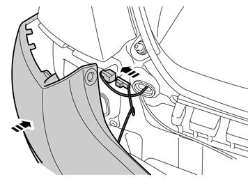
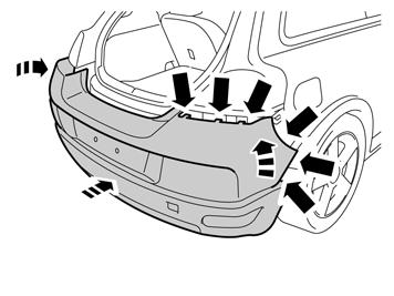
6 4 IMG A Illustration A Remove the bumper cover from the body by carefully prying off the ends using a weatherstrip tool. Pull off the cover under the tail lamp and from the rear edge of the wing on each side. It is secured by four clips at the tail lamp and four in the rear edge of the rear wing. Pull the bumper cover straight back. Illustration B Unplug the connector for the licence plate lighting on the left side. If the car is equipped with reverse warning, then unplug the connector for this on the right side. 5B IMG IMG Page 6 / 42

7 6 Wheel housing edges Carefully bend loose the rear fender's panel starting at the trailing edge and then forward. Bend with the weatherstrip tool right at the side of the clips. The panel is fastened with a catch at the trailing edge and five clips all the way around. The panel shall not be used again. Note! Do not damage the paint work. IMG Loosen the fender liner with the three clips from the panel's clips by first pressing it in until the three clips release, and then folding it down. Remove the three clips in the fender liner's upper edge and all clips in the fender edge. New clips are included in the kit. Clean the fender edge. IMG Page 7 / 42
8 8 IMG IMG Page 8 / 42


9 10 Carefully bend loose the front fender's panel starting at the leading edge and then backward. Bend with the weatherstrip tool right at the side of the clips. The panel is fastened with a catch at the leading edge and seven clips all the way around. The panel shall not be used again. Note! Do not damage the paint work. IMG Loosen the fender liner with the three clips from the panel's clips by first pressing it in until the three clips release, and then folding it down. Remove the three clips in the fender liner's upper edge and all clips in the fender edge. New clips are included in the kit. Clean the fender edge. Repeat steps 6-11 for the other side. IMG Page 9 / 42

10 12 Front bumper cover Remove the panel to the left and right fog light by carefully pressing in the catches in the panel's upper edge with a weatherstrip tool and pull it loose. The panel is fastened with six catches. IMG Steps apply to cars with 4-cylinder engine where electric engine heater is installed Remove the seven screws from the engine splash guard. J Page 10 / 42
11 14 Remove the left front wheel. Remove the five screws holding the bumper cover in the wing liner on the left and right-hand sides. J Remove the nut holding the left-hand wing liner to the front member. Bend the front edge of the left-hand wing liner up over the brake calliper. J Page 11 / 42
 at the brake pipe and from clamps along the side member's underside.")
12 16 Remove the lock sleeve over the joint to the engine heater's cable on the left side by the stay on the sub-frame. Unplug the connectors. J Loosen the cable from the double clamp (1) at the brake pipe and from clamps along the side member's underside. J Page 12 / 42
13 18 Loosen the ground cable from the leading edge of the side member's outside. J Cut off the cable tie (1) that holds the cable to the left radiator bracket. J Page 13 / 42
14 20 Steps apply to cars with 5-cylinder engine where electric engine heater is installed Remove the seven screws from the engine splash guard. J Remove the left and right-hand front wheels. Remove the five screws holding the bumper cover in the wing liner on the left and right-hand sides. J Page 14 / 42

15 22 Remove the nut holding the left-hand wing liner to the front member. Bend the front edge of the left-hand wing liner up over the brake calliper. J Remove the lock sleeve over the joint to the engine heater's cable on the right side by the stay on the sub-frame. Unplug the connectors. Applies to cars for USA For cars to the USA there is no splice (joint) on the cable. Then this is loosened instead by the engine heater. J Page 15 / 42
16 24 Loosen the cable from the double clamp on the brake pipe on the right side in the engine compartment. J Remove the cable tie that holds the cable to the cable harness at the top in the engine compartment. J Page 16 / 42


17 26 Loosen the cable from the clips along the metal edge in the trailing edge of the engine compartment. IMG Loosen the cable from the double clamp by the brake pipe in the top edge of the bulkhead on the left side. J Page 17 / 42
18 28 Loosen the cable from the double clamp (1) at the brake pipe and from clamps along the side member's underside. J Does not apply to cars for USA. Loosen the ground cable from the leading edge of the side member's outside. J Page 18 / 42
. Remove the clips.")
19 30 Cut off the cable tie (1) that holds the cable to the left radiator bracket. J Applies to all models Push in the centre of the five clips (1). Remove the clips. Remove the two screws (2). J Page 19 / 42

20 32A Illustration A Remove the covers for the nozzles for the headlamp washers on the right and left-hand sides. Carefully grip the cover. Pull the cover out until the catch becomes accessible. Illustration B Press the catch up and remove the cover. Do not damage the painted surfaces or the high-pressure washer nozzles. 32B J J Remove the four screws that hold the bumper's lower part in the baffle. Remove the spring nuts that hold the baffle in the bumper casing's lower part on both sides. IMG Page 20 / 42

21 34A Illustration A Carefully pry off the corner of the bumper cover using a weatherstrip tool until the three hooks on the inside release. Illustration B Remove the bumper cover with air baffle by grasping the ends and pulling forwards until the remaining hooks under the lamps release. Note! Get help from a colleague for this procedure. 34B IMG Disconnect the connectors for the fog lamps or parking assistance if applicable. IMG Page 21 / 42
22 35 Door sill panel IMG Drive out the centre pin in the clips on the underside of the bottom sill's panel. On the two front clips, the centre pins may have to be drilled out to be able to remove the clips. Turn loose the panel from the bottom sill's underside so that the clips come loose. IMG Page 22 / 42

23 37 Remove the bottom sill's panel by carefully bending it loose directly opposite the clips along its entire length. Note! Do not damage the paint work. Remove the rubber strip from the panel. Lay away the panel but the rubber strip is to be used again. Repeat steps for the other side. IMG Installation 38 Installation Rear spoiler Applies to cars with reverse warning Loosen the clips for the cable harness for the reverse warning's sensors from the lower part's catches. IMG Page 23 / 42


24 39 Get help from a colleague for this procedure. Place the bumper casing on a surface that will not damage the painted surface. Carefully bend and pull loose the bumper's lower part from the upper part. It is fastened with catches all the way around. The lower part shall not be used again. Note! Do not damage the painted surface on the upper part. IMG Get help from a colleague for this procedure. Take the rear spoiler from the kit and press the upper part into it. Make sure that all catches engage. Note! Do not damage the painted surface on the upper part. IMG Page 24 / 42
25 41 Applies to cars with reverse warning Press in the clips for the cable harness for the reverse warning in the spoiler's catches. IMG Press on the reflectors from the kit on the spoiler's ends. Applies to cars for USA market Paint the covers from the kit according to information in VIDA "Repair painting section 8 (80)". Press on the covers. IMG Page 25 / 42

26 43 Insert the plastic string for the towing eye's in the rectangular hole in the lower edge of the opening. Press in the panel in the opening. IMG Applies to cars where the end-pipe is not to be visible. Press on the cover for the exhaust pipe opening so that the catch at the top edge engages. Press in the two clips in the slots on the cover. IMG Page 26 / 42
27 45 IMG IMG Page 27 / 42

28 47 IMG IMG Page 28 / 42


29 49 Front spoiler Loosen the holder from the bumper casing's upper part on both sides. IMG Get help from a colleague for this procedure. Place the bumper casing on a surface that will not damage the painted surface. Carefully bend and pull loose the bumper's lower part from the upper part. It is fastened with catches all the way around. The lower part shall not be used again. Note! Do not damage the painted surface on the upper part. IMG Page 29 / 42

30 51 Take the front spoiler from the kit. Note! The unpainted spoiler must be painted first. Clean the marked areas underneath the spoiler where the antichafing protector is to be located. Use isopropanol. Wipe dry. IMG Remove the protective tape from the anti-chafing protector. IMG Page 30 / 42


31 53 Position and secure the anti-chafing protector along the edges of the spoiler at the rear edge. IMG Press the anti-chafing protector at the rear edge forwards. IMG Page 31 / 42

32 55 Remove the protective tape from the anti-chafing protector. IMG Press the anti-chafing protector into place. IMG Page 32 / 42

33 57 Remove the protective tape from the anti-chafing protector. IMG Press the anti-chafing protector into place. Repeat steps for the other side. IMG Page 33 / 42

34 59 Press the front spoiler into the upper section. Make sure that all catches engage. Note! Do not damage the painted surface on the upper part. IMG Reinstall the bumper cover. Make sure that the spoiler fits in the leading edge on the baffle. IMG Page 34 / 42
35 61 Secure the bumper casing with the clips (1) and screws (2). J Pull up the high-pressure nozzle from the bumper casing and install the covers on both sides. IMG Connect the cable for the engine heater, if applicable. Route and clamp it in the same way as it was installed before. Replace cut cable ties with new ones. Note! Do not clamp the cable directly to AC pipes, fuel lines, brake pipes or power steering hoses and pipes. Make sure the cable does not chafe against sharp edges or moving parts in the engine compartment. Remount the front wheel and tighten the wheel bolts to 90 Nm (66 lbf.ft.). Page 35 / 42

36 64 Tighten the spoiler's brackets to the baffle. Tighten the baffle's outer screw on both sides. IMG IMG Page 36 / 42
37 66 IMG Door sill panel Get a new bottom sill panel and new clips from the kit. Replace all clips. Install the rubber strip from the old panel on the new. IMG Page 37 / 42


38 68 Press in the new panel in the bottom sill. Make sure all catches engage. IMG Get new clips from the kit and secure the panel in the lower edge. Repeat steps for the other side. IMG Page 38 / 42
39 70 Wheel housing edges Get the new panel and new clips for the fender edge from the kit. Install new clips in the panel. IMG Get new clips from the kit and install these around the fender edge. IMG Page 39 / 42
40 72 Reinstall the fender liner. Get new clips from the kit and press in to the fender liner. Press in the fender liner with clips in the fender edge's clips. Make sure that the clips really snap into place. IMG Press in the new panel on the fender edge. Make sure all catches engage. IMG Page 40 / 42
41 74 IMG IMG Page 41 / 42
42 76 IMG Repeat steps for all wheel housing edges. IMG Page 42 / 42
Installation instructions, accessories. Electric engine block heater, connector outlet, 4-cyl
 Installation instructions, accessories Instruction No 31359444 Version 1.2 5 Part. No. 31359438 Electric engine block heater, connector outlet, 4-cyl IMG-247665 Volvo Car Corporation Electric engine block
Installation instructions, accessories. Parking assistance, rear
 Installation instructions, accessories Instruction No 31330676 Version 1.4 Part. No. 30758088, 9487266, 30786087, 31359215 Parking assistance, rear Volvo Car Corporation Parking assistance, rear- 31330676
Installation instructions, accessories. Electric engine block heater, 230V, 5 cyl diesel
 Installation instructions, accessories Instruction No 30795311 Version 1.2 Part. No. 31373138 Electric engine block heater, 230V, 5 cyl diesel IMG-256423 Volvo Car Corporation Electric engine block heater,
Installation instructions, accessories. Satellite radio, Sirius
 Installation instructions, accessories Instruction No 31201184 Version 1.3 5 Part. No. 31296261, 31359449 Satellite radio, Sirius IMG-246543 Volvo Car Corporation Satellite radio, Sirius- 31201184 - V1.3
Installation instructions, accessories - Fuel driven heater 912-D
 XC90 Section Group Weight(Kg/Pounds) Year Month 8 87 2002 10 XC90 2003 D5244T, XC90 2004 D5244T, XC90 2005 D5244T AW50/51 AWD, XC90 2006 D5244T, XC90 2006 D5244T AW50/51 AWD D5244T R8703687 Page 1 of 20
Installation instructions, accessories - Electric engine block heater
 S60 / V70 (00-08) / S80 (-06) / V70 XC (01-) / XC70 (-07) / XC90 Section Group Weight Year Month (Kg/Pounds) 8 876 2/4.4 2006 09 S60 2001 D5244T, S60 2002 D5244T, S60 2002 D5244T2, S60 2003 D5244T, S60
Installation instructions, accessories RTI S80
 Installation instructions, accessories Instruction No 8685714 Version 1.0 5 Part. No. RTI S80 Volvo Car Corporation RTI S80-8685714 - V1.0 Page 1 / 25 Equipment A0000161 A0000162 A0801178 D8802049 Page
USB and ipod Music interface
 Installation instructions, accessories Instruction No 30775542 Version 1.2 Part. No. USB and ipod Music interface Volvo Car Corporation USB and ipod Music interface- 30775542 - V1.2 Page 1 / 16 Equipment
1 of 21 9/30/2011 3:16 PM
 Engine Block Heater, Service and Repair, Removal and Replacement: Ele... 1 of 21 9/30/2011 3:16 PM 2005 Volvo S60 L5-2.5L Turbo VIN 59 B5254T2 Engine Block Heater Service and Repair, Removal and Replacement:
393: Multimedia system for the rear seat Multimedia system for the rear seat
 393: Multimedia system for the rear seat S80 (07-), 2008, B8444S, TF-80SC AWD, L.H.D, YV1AH852881073834, 073834 4/1/2013 PRINT 393: Multimedia system for the rear seat Multimedia system for the rear seat
Installation instructions, accessories. Subwoofer
 Installation instructions, accessories Instruction No 9162298 Version 1.0 5 Part. No. Subwoofer Volvo Car Corporation Subwoofer - 9162298 - V1.0 Page 1 / 24 Equipment A0000162 A0801178 A0000161 R8802817
Instruction No Version Part. No , , , , , , , ,
 Instruction No Version Part. No. 30744180 1.2 30794160, 30794013, 30794026, 30794039, 31213192, 30794102, 30794138, 30794151, 30794075 Body kit IMG-256183 Page 1 / 13 Equipment A0000162 A0000163 IMG-239940
Installation instructions, accessories - Alarm, basic kit S60 / S80 / V70 / V70 XC / XC /
 S60 / S80 / V70 / V70 XC / XC70 Section Group Weight(Kg/Pounds) Year Month 3 36 0.67/1.47 2005 05 S60 2001, S60 2002, S60 2003, S60 2004, S60 2005, S60 2006, S60 2007, S60 2008, S60 2009, S80 (-06) 1999,
Sensus Connected Touch
 Installation instructions, accessories Instruction No 31350401 Version 1.2 Part. No. 31399164, 31399165, 31399166 Sensus Connected Touch IMG-378798 Volvo Car Corporation Sensus Connected Touch- 31350401
Installation instructions, accessories. Polestar Performance Intake and Exhaust kit
 Installation instructions, accessories Instruction No 31664128 Version 1.0 Part. No. 31664126, 31664125, 31664522, 31664523 Polestar Performance Intake and Exhaust kit Volvo Car Corporation Polestar Performance
Installation instructions, accessories. Multimedia monitor with DVD, Dual screen. Multimedia monitor with DVD, Dual screen V1.
 Installation instructions, accessories Instruction No 30756560 Version 1.2 5 Part. No. 30756177 Multimedia monitor with DVD, Dual screen Volvo Car Corporation Multimedia monitor with DVD, Dual screen-
Installation instructions, accessories. Parking assistance, camera, front (Plug-in Hybrid)
") Installation instructions, accessories Instruction No 31428779 Version 1.0 5 Part. No. 9487189 Parking assistance, camera, front (Plug-in Hybrid) IMG-374543 Volvo Car Corporation Parking assistance, camera,
Installation instructions, accessories Instruction No 31428779 Version 1.0 5 Part. No. 9487189 Parking assistance, camera, front (Plug-in Hybrid) IMG-374543 Volvo Car Corporation Parking assistance, camera,
394: Handsfree, Bluetooth Handsfree, Bluetooth
 394: Handsfree, Bluetooth S80 (07-), 2008, B8444S, TF-80SC AWD, L.H.D, YV1AH852881073834, 073834 4/1/2013 PRINT 394: Handsfree, Bluetooth Handsfree, Bluetooth Installation instruction: 31310098 INTRODUCTION
900 Installation instructions. SCdefault
 SCdefault 900 Installation instructions SITdefault Parking assistance (SPA) MONTERINGSANVISNING INSTALLATION INSTRUCTIONS MONTAGEANLEITUNG INSTRUCTIONS DE MONTAGE Accessories Part No. Group Date Instruction
Installation instructions, accessories - Volvo Navigation System, widescreen
 S60 Section Group Weight(Kg/Pounds) Year Month 3 39 2001 04 S60 2001, S60 2002 Page 1 of 21 Page 2 of 21 Required tools A0000162 A0000161 A0801178 M8802509 M3903563 Page 3 of 21 M3903565 M8503983 Page
 INSTALLATION INSTRUCTIONS Accessory Application Publications No. AII 33173 UNDER 2007 ODYSSEY Issue Date JULY 2006 PART LIST Front under spoiler 5 Stepped bolts TOOLS AND SUPPLIES REQUIRED Phillips screwdriver
Installation instructions, accessories - Bluetooth, swan neck microphone
 S80 (-06) / V70 XC (01-) / XC70 (-07) / S60 / V70 (00-08) / XC90 / S40 (04-) / V50 / C70 (06-) / S80 (07-) / C30 / V70 (08-) / XC70 (08-) Section Group Weight Year Month (Kg/Pounds) 3 394 0.5/1 2006 10
Installation instructions, accessories. Handsfree, Bluetooth
 Installation instructions, accessories Instruction No 31310097 Version 1.3 5 Part. No. 31285547 Handsfree, Bluetooth Volvo Car Corporation Handsfree, Bluetooth- 31310097 - V1.3 Page 1 / 28 Equipment A0000162
Installation instructions, accessories TV NTSC/PAL
 Instruction No Version Part. No. 8637033 1.0 5 TV NTSC/PAL Page 1 / 17 Page 2 / 17 INTRODUCTION Read through all of the instructions before starting installation. Notifications and warning texts are for
Installation instructions, accessories - Bluetooth, Mute kit XC / Volvo Car Corporation Göteborg, Sweden
 XC90 Section Group Weight(Kg/Pounds) Year Month 3 393 0.5/1.1 2006 11 XC90 2003, XC90 2004, XC90 2005, XC90 2006, XC90 2007, XC90 2008, XC90 2009, XC90 2010 Page 1 of 15 Required tools A0000162 IMG-242205
Installation instructions, accessories
 Volvo Car Corporation Göteborg, Sweden Installation instructions, accessories S60/V70 (00-)/V70XC (01-)/S80/XC90 Section Group Weight (Kg/Pounds) Year Month 8 89 2002 06 Tow bar wiring, 13-pin M3702161
Installation instructions, accessories - Bluetooth XC / Volvo Car Corporation Göteborg, Sweden
 XC90 Section Group Weight(Kg/Pounds) Year Month 3 393 1/2.2 2008 03 XC90 2003, XC90 2003, XC90 2004, XC90 2004, XC90 2005, XC90 2005, XC90 2006, XC90 2006, XC90 2007, XC90 2007, XC90 2008, XC90 2008, XC90
Installation instructions, accessories - Rear Seat Entertainment
 XC90 Section Group Weight(Kg/Pounds) Year Month 3 39 2004 10 XC90 2003, XC90 2004, XC90 2005, XC90 2006, XC90 2007, XC90 2008 Replaces issue: 2003 12 J3904620 Page 1 of 18 Required tools A0000162 A0000163
Front Bumper Fascia Replacement
 Page 1 of 10 2008 Pontiac G8 G8 Service Manual Body Repair Bumpers and Fascias Repair Instructions Document ID: 2044380 Front Bumper Fascia Replacement Removal Procedure Caution: Refer to Safety Glasses
Installation instructions, accessories. Towbar, detachable (Plug-in Hybrid)
") Installation instructions, accessories Instruction No 31373200 Version 1.2 5 Part. No. 31359557, 30791002 Towbar, detachable (Plug-in Hybrid) IMG-371662 Volvo Car Corporation Towbar, detachable (Plug-in
Installation instructions, accessories Instruction No 31373200 Version 1.2 5 Part. No. 31359557, 30791002 Towbar, detachable (Plug-in Hybrid) IMG-371662 Volvo Car Corporation Towbar, detachable (Plug-in
54531/ FORD FUSION
 54531/51531 54531/51531 13-15 FORD FUSION 13-15 FORD FUSION FORD FUSION Upper Class Grille w/ Bars TOOLS REQUIRED: Socket Set Flat/Phillips Screw Drivers Torx Bits Plastic Pry Bar 3/16 Drill Bit and Drill
PREMIUM FRONT BUMPER FOR RAM 2500/3500. AEV30239AJ Last Updated: 09/05/17 INSTALLATION GUIDE
 PREMIUM FRONT BUMPER FOR RAM 2500/3500 AEV30239AJ Last Updated: 09/05/17 INSTALLATION GUIDE PLEASE READ BEFORE YOU START TO GUARANTEE A QUALITY INSTALLATION, WE RECOMMEND READING THESE INSTRUCTIONS THOROUGHLY
INSTALLATION INSTRUCTIONS
 INSTALLATION INSTRUCTIONS Accessory S Application 2010 INSIGHT Publications No. AII 40881 Issue Date MARCH 2009 PARTS LIST Right fog light bracket D Fog Lights Kit P/N 08V31-TM8-100 Left fog light Fog
SCdefault. 900 Installation instructions. Accessories Part No. Group Date Instruction Part No. Replaces :40-05 Sep
 SCdefault 900 Installation instructions SITdefault Parking assistance (SPA) MONTERINGSANVISNING INSTALLATION INSTRUCTIONS MONTAGEANLEITUNG INSTRUCTIONS DE MONTAGE Accessories Part No. Group Date Instruction
54531/ FORD FUSION
 2014-2015 FORD Upper Class Grille w/ Bars TOOLS REQUIRED: Socket Set Flat/Phillips Screw Drivers Torx Bits Plastic Pry Bar 3/16 Drill Bit and Drill Motor PARTS LIST: (4) #8 u-nuts (2) seal brackets (driver
 Page 1 of 7 Bumpers - Front Bumper Cover Removal and Installation Removal 1. WARNING: Do not work on or under a vehicle supported only by a jack. Always support the vehicle on safety stands. Raise and
INSTALLATION INSTRUCTIONS ELEVATION FRONT BUMPER DODGE RAM
 INSTALLATION INSTRUCTIONS PARTS LIST: 1 Elevation Bumper Assembly 24 12mm x 37mm OD x 3mm Flat Washers 2 Frame Mounting Brackets 12 12mm Nylon Lock Nuts 8 12-1.75mm x 50mm Hex Bolts 2 License Plate Mounting
TESLA MODEL S REAR UNDER SPOILER & DIFFUSER SYSTEM
 TESLA MODEL S Thank you for purchasing your Unplugged Performance Rear Under Spoiler & Diffuser System for the Tesla Model S! Please read this manual carefully prior to installation. REAR UNDER SPOILER
Wiper arm and wiper motor, headlamp, replacing
 "VCC137971 EN 20110112" file://c:\info\vv132007\ie\en\31\vcc137971.htm Page 1 of 2 Wiper arm and wiper motor, headlamp, replacing Removal Preparations Switch off the ignition. Headlamp wiper arm Lift up
LED Fog Light. Conflicts Note: 1226, General Applicability Fits Models Additional Items Required For Installation
 LED Fog Light Year & Model Part Number Conflicts Note: 1226, 1228 2017 Prius TPR-817 General Applicability Fits Models 1221 1225 1223 1227 1224 Additional Items Required For Installation Items 1 N/A 2
INSTALLATION GUIDE PREMIUM FRONT BUMPER FOR RAM AEV30304AA Last Updated: 09/18/17
 AEV30304AA Last Updated: 09/18/17 PREMIUM FRONT BUMPER FOR RAM 1500 INSTALLATION GUIDE PLEASE READ BEFORE YOU START To guarantee a quality installation, we recommend reading these instructions thoroughly
INSTALLATION INSTRUCTIONS
 INSTALLATION INSTRUCTIONS Accessory HITCH Application 2009 CR-V Publications No. AII 40373 Issue Date AUG 2008 PARTS LIST Plain washer, 12 mm Trailer Hitch Kit P/N 08L92-SWA-100 Trailer hitch 6 Spring
UNPACK AND IDENTIFY THE FOLLOWING PARTS.
 SUT-350-AIT ASSEMBLY REQUIREMENTS *Torque all T-bolt nuts to 35-40 foot pounds. *Check all lights before towing. *Tire pressure not to exceed recommendation on serial tag. *Re-torque wheel nuts after first
SCION tc FOG LIGHT. Part Number: STC-312 / STC-812
 SCION tc 2011-2013 FOG LIGHT Part Number: STC-312 / STC-812 Kit Contents Item # Quantity Reqd. Description 1 2 Fog Lamps 2 2 Fog Light bezels 3 1 Switch Assembly 4 1 Fog Light Operation guide 5 1 Harness
INSTALLATION INSTRUCTIONS
 INSTALLATION INSTRUCTIONS Accessory S P/N 08V67-SJC-101 Application 2012 RIDGELINE Publications No. AII 12006 Issue Date NOV 2011 PARTS LIST Back-up sensor harness 3 Wire ties with small clips (2 Not used)
Current Range Rover Sport STRUT Collection Installation Manual
 2014 - Current Range Rover Sport STRUT Collection Installation Manual 1 1. Removing Main Grille and Lower Fascia 1.1 Run a line of low tack masking tape across the front of the bumper below the grille
FOG LAMPS INSTALL KIT
 FOG LAMPS INSTALL KIT PT CRUISER INSTALLATION INSTRUCTIONS Read entire instructions thoroughly before starting. For proper aiming of fog lamps, follow procedures in the service manual. NOTES: Left and
INSTALLATION INSTRUCTIONS
 INSTALLATION INSTRUCTIONS Accessory Application Publications No. ATTACHMENT (EX-L WITH NAVI) 2008 RIDGELINE AII 36587 Issue Date MAY 2007 PARTS LIST Attachment Kit P/N: 08B21-SJC-102 Template Rear camera
INSTALLATION INSTRUCTIONS
 INSTALLATION INSTRUCTIONS Accessory S P/N 08V67-SJC-101 Application 2010 RIDGELINE Publications No. AII 42117 Issue Date AUG 2009 PARTS LIST Back-up sensor harness 3 Wire ties with small clip (2 Not used)
TOYOTA PRIUS C FOG LIGHT (Halogen & LED)
") TOYOTA PRIUS C 2012-14 FOG LIGHT (Halogen & LED) Part Number: TPC-312 / TPC-812 Kit Contents Item # Quantity Reqd. Description 1 2 Fog Lamps 2 2 Bezels 3 1 Switch Assembly 4 1 Fog Light Operation guide
TOYOTA PRIUS C 2012-14 FOG LIGHT (Halogen & LED) Part Number: TPC-312 / TPC-812 Kit Contents Item # Quantity Reqd. Description 1 2 Fog Lamps 2 2 Bezels 3 1 Switch Assembly 4 1 Fog Light Operation guide
SUT-450-I ASSEMBLY REQUIREMENTS
 SUT-450-I Torque wrench, carpenters square, wire cutters, Phillips screwdriver, 7/16, 9/16, and 3/4 combination wrenches, ratchet, 9/16,3/4,13/16, and 7/8 sockets. ASSEMBLY REQUIREMENTS *Torque all T-bolt
Replacing the fuel tank
 Page 1 of 11 Replacing the fuel tank Special tools: 999 5720 Preparation Note! On cars up to chassis number 104221 the fuel filler pipe must be replaced when the fuel tank is replaced. Drain the fuel from
 Page 1 of 10 43: Transmission, automatic, B5254T2, AW50/51 AWD V70 XC (01-) / XC70 (-07), 2004, B5254T2, AW50/51 AWD, L.H.D, YV1SZ59H241147306, 147306 15/10/2011 PRINT 43: Transmission, automatic, B5254T2,
29048, 29049, 29050, 29051, 29052, 29053, 29054,
 May 1, 2018 Lit. No. 29206, Rev. 13 29048, 29049, 29050, 29051, 29052, 29053, 29054, 29400 7 HARNESS KIT 3 PORT ISOLATION MODULE LIGHT SYSTEM w/3 PLUG SYSTEM HARNESSES Installation Instructions Read this
SDHQ F-150 Winch Mount System Installation
 SDHQ 2015+ F-150 Winch Mount System Installation Recommended Tools: Door panel removal tool Needle Nose Pliers 10mm Socket or Wrench 13 mm or ½ Socket (⅜ Drive) 14 mm or 9/16 Socket (⅜ Drive) 21 mm or
Part Number: T4R-2IN1
 Date: 12.11.2014 TOYOTA HIGHLANDER 2015 LED Fog Light & DRL 2in1 Part Number: T4R-2IN1 Kit Contents Item # Quantity Reqd. Description 1 2 DRL + Fog Light Housing 2 1 Driver Box 3 1 Harness bag 4 1 User
Part Number: T4R-2N1. Hardware Bag Contents. General Applicability. Conflicts - Limited Models
 Date: 12.11.2014 TOYOTA HIGHLANDER 2014-2016 LED Fog Light & DRL 2 in 1 Part Number: T4R-2N1 Kit Contents Item # Quantity Reqd. Description 1 2 DRL + Fog Light Housing 2 1 Driver Box 3 1 Harness bag 4
Installation instruction do88 Intercooler for SAAB 9-3 1,9 TTiD
 Installation instruction do88 Intercooler for SAAB 9-3 1,9 TTiD This instruction shows how to replace the OEM intercooler with this performance intercooler. At this type of installation we always recommend
1. Front Fascia Removal 1.1 Remove the 6 plastic clips that secure the upper valance, then remove. 1.2 Remove 6 upper bolts that hold the grille and f
 STRUT 2015 GMC Denali Collection Installation Manual " 1. Front Fascia Removal 1.1 Remove the 6 plastic clips that secure the upper valance, then remove. 1.2 Remove 6 upper bolts that hold the grille and
PRELIMINARY INSTALLATION INSTRUCTIONS PARTS LIST. Combination light switch Right fog light. 4 Self-tapping washer-screws.
 INSTALLATION INSTRUCTIONS Accessory S P/N 08V31-SCV-100D Application 2009 ELEMENT (SC) Publications No. AII 40515 Issue Date OCT 2008 PARTS LIST Combination light switch Right fog light Left fog light
29048, 29049, 29050, 29051, 29052, 29053, 29054,
 April 15, 2014 Lit. No. 29206, Rev. 11 29048, 29049, 29050, 29051, 29052, 29053, 29054, 29400 5 HARNESS KIT 3 PORT ISOLATION MODULE LIGHT SYSTEM w/3 PLUG SYSTEM HARNESSES Installation Instructions Read
INSTALLATION INSTRUCTIONS
 INSTALLATION INSTRUCTIONS Accessory Application CR-V Publications No. AII 32953-34081 Issue Date NOV 2006 PARTS LIST 2 Corner sensor clips Backup Sensor Attachment Kit P/N 08V67-SWA-100A Back-up sensor
INSTALLATION INSTRUCTIONS
 INSTALLATION INSTRUCTIONS Accessory Application Publications No. SYSTEM ACCORD 2-DOOR (LX/EX L4, LX V6) AII 25749 Issue Date FEB 2004 PARTS LIST Double-sided adhesive tape XM Radio Attachment Kit : P/N
INSTALLATION INSTRUCTIONS
 INSTALLATION INSTRUCTIONS Accessory Application Publications No. AII 44415 2011 CIVIC 4-DOOR Issue Date AUG 2010 PARTS LIST Trunk spoiler 2 Cap nuts 2 Screws Left trunk spring (marked yellow) Right trunk
SCdefault. 900 Installation instructions
 SCdefault 900 Installation instructions SITdefault Sports chassis MONTERINGSANVISNING INSTALLATION INSTRUCTIONS MONTAGEANLEITUNG INSTRUCTIONS DE MONTAGE Accessories Part No. Group Date Instruction Part
INSTALLATION INSTRUCTIONS
 INSTALLATION INSTRUCTIONS Accessory Application Publications No. S P/N 08V31-SCV-100B 2008 ELEMENT (SC) AII 36532 Issue Date MAY 2007 PARTS LIST Relay bracket Right fog light Relay Left fog light Fuse
FRAME AND BUMPERS 13-1 FRAME AND BUMPERS TABLE OF CONTENTS
 WJ FRAME AND BUMPERS 13-1 FRAME AND BUMPERS TABLE OF CONTENTS BUMPERS... 1 FRAME... 5 BUMPERS TABLE OF CONTENTS DESCRIPTION AND OPERATION BUMPERS...1 AND FRONT FASCIA...1 FRONT ABSORBER...2 REAR FASCIA...2
INSTALLATION INSTRUCTIONS
 COLD AIR INTAKE INSTALLATION INSTRUCTIONS PART NUMBER D760-0390C APPLICATION: 1999-2003 E39 M5 PARTS LIST 1 Left Aluminum Intake Tube 1 Air Pump Bracket (A) 1 Right Aluminum Intake Tube 1 Air Pump Bracket
INSTALLATION GUIDE Front Bumper. KL Cherokee (Trailhawk)
") INSTALLATION GUIDE Front Bumper KL Cherokee (Trailhawk) Included Hardware: Sample Sample Sample Skill Level: 5/5 stars (Professional install recommended) Disclaimer Expedition One is not responsible for
INSTALLATION GUIDE Front Bumper KL Cherokee (Trailhawk) Included Hardware: Sample Sample Sample Skill Level: 5/5 stars (Professional install recommended) Disclaimer Expedition One is not responsible for
29048, 29049, 29050, 29051, 29052, 29053, 29054,
 April 15, 2014 Lit. No. 29225, Rev. 11 29048, 29049, 29050, 29051, 29052, 29053, 29054, 29400 5 HARNESS KIT 3 PORT ISOLATION MODULE LIGHT SYSTEM w/2 PLUG SYSTEM HARNESSES Installation Instructions Read
INSTALLATION INSTRUCTIONS
 AUTOMOTIVE PRODUCTS, INSTALLATION INSTRUCTIONS ULTIMATE BULL BAR APPLICATION: 2009-2018 Dodge Ram 1500 (Excl. Rebel Model) 2019 Dodge Ram 1500 Classic PART NUMBER: 32-1960, 32-1965, 32-1960L, 32-1965L
Installation instruction do88 Intercooler for SAAB 9-3SS/SC 2,8 V6 Turbo
 Installation instruction do88 Intercooler for SAAB 9-3SS/SC 2,8 V6 Turbo This instruction shows how to replace the OEM intercooler with this performance intercooler. At this type of installation we always
1 of 2 5/25/17, 4:57 PM
 1 of 2 5/25/17, 4:57 PM Overview - Bumper Cover, Audi Q5 S-Line and Audi SQ5 If the vehicle has lane change assistance, the lane change assistance control module (J769) / (J770) must be recalibrated. 1
TOYOTA COROLLA L, LE FOG LIGHT (Halogen and LED) Part Number: TCO-314 / TCO-814
 Part Number: TCO-314 / TCO-814") TOYOTA COROLLA L, LE 2014-16 FOG LIGHT (Halogen and LED) Part Number: TCO-314 / TCO-814 Kit Contents Item # Quantity Reqd. Description 1 2 Light Housings 2 2 Fog Light bezels 3 1 Switch Assembly 4 1 Fog
TOYOTA COROLLA L, LE 2014-16 FOG LIGHT (Halogen and LED) Part Number: TCO-314 / TCO-814 Kit Contents Item # Quantity Reqd. Description 1 2 Light Housings 2 2 Fog Light bezels 3 1 Switch Assembly 4 1 Fog
SCION tc FOG LIGHT (Halogen or LED)
") Part Number: STC-314 / STC-814 Kit Contents Item # Quantity Reqd. Description 1 2 Fog Lamps 2 2 Fog Light bezels 3 1 Switch Assembly 4 1 Fog Light Operation guide 5 1 Harness Bag Hardware Bag Contents
Part Number: STC-314 / STC-814 Kit Contents Item # Quantity Reqd. Description 1 2 Fog Lamps 2 2 Fog Light bezels 3 1 Switch Assembly 4 1 Fog Light Operation guide 5 1 Harness Bag Hardware Bag Contents
INSTALLATION INSTRUCTIONS
 INSTALLATION INSTRUCTIONS Accessory S Application 2011 PILOT Publications No. AII 43298 Issue Date MARCH 2010 PARTS LIST Back-up Sensor Attachment Kit P/N 08V67-SZA-100A Back-up sensor harness Fuse label
This is one of our XL series brackets,
 R O A D M A S T E R, I N C. MOUNTING BRACKET KIT FAILURE TO FOLLOW THESE INSTRUCTIONS CAN RESULT IN DEATH, PERSONAL INJURY OR PROPERTY DAMAGE This is one of our XL series brackets, which allows the visible,
SCdefault. 900 Installation instructions
 SCdefault 900 Installation instructions SITdefault Installation kit, extra lights MONTERINGSANVISNING INSTALLATION INSTRUCTIONS MONTAGEANLEITUNG INSTRUCTIONS DE MONTAGE Accessories Part No. Group Date
INSTALLATION INSTRUCTIONS
 INSTALLATION INSTRUCTIONS Accessory TRAILER HITCH Application 2012 ODYSSEY Publications No. AII 46755 Issue Date SEP 2011 PARTS LIST Trailer Hitch Kit P/N 08L92-TK8-100 Trailer Hitch Harness Kit P/N 08L91-TK8-100
OIL COOLER KIT INSTALLATION INSTRUCTIONS PART NUMBER D E92 335i/xi without stock oil cooler
 OIL COOLER KIT INSTALLATION INSTRUCTIONS PART NUMBER D570-0921 APPLICATION 2007-08 E92 335i/xi without stock oil cooler Congratulations for being selective enough to use a Dinan Engineering Oil Cooler
Part Number: TCO-314 / TCO-814
 Date: 05.02.2014 TOYOTA COROLLA L, LE 2014-15 FOG LIGHT (Halogen and LED) Part Number: TCO-314 / TCO-814 Kit Contents Item # Quantity Reqd. Description 1 2 Light Housings 2 2 Fog Light bezels 3 1 Switch
29048, 29049, 29050, 29051, 29052, 29053, 29054,
 April 15, 2014 Lit. No. 29206, Rev. 11 29048, 29049, 29050, 29051, 29052, 29053, 29054, 29400 5 HARNESS KIT 3 PORT ISOLATION MODULE LIGHT SYSTEM w/3 PLUG SYSTEM HARNESSES Installation Instructions Read
RS5mesh style Grille. Audi A5/S5. Installation Instructions. pre-facelift ES best viewed in Acrobat Reader
 Audi A5/S5 pre-facelift RS5mesh style Grille Installation Instructions ES2627648 This tutorial is provided as a courtesy by ECS Tuning. best viewed in Acrobat Reader Proper service and repair procedures
INSTALLATION INSTRUCTIONS
 INSTALLATION INSTRUCTIONS Accessory TRAILER HITCH Application 2011 ODYSSEY Publications No. AII 43937 Issue Date SEP 2010 PARTS LIST Trailer Hitch Kit P/N 08L92-TK8-100 Trailer Hitch Harness Kit P/N 08L91-TK8-100
Part Number: T4R-2N1. Hardware Bag Contents. General Applicability Models with factory fog light. Conflicts -
 Date: 07.30.2015 TOYOTA TUNDRA 2014-2016 LED Fog Light & DRL 2 in 1 Part Number: T4R-2N1 Kit Contents Item # Quantity Reqd. Description 1 2 DRL + Fog Light Housing 2 1 Driver Box 3 1 Harness bag 4 1 User
LGT-311L Bumper LED Light Kit EZ-Go RXV Installation Instructions
 LGT-311L Bumper LED Light Kit EZ-Go RXV Installation Instructions Caution: Please read through the instructions carefully. Before starting this project, remove the system s positive and negative connections
ED 42. ENGINE HOOD / DOOR FRONT DOOR (w/o Power Window)
") 42 ENGINE HOOD / DOOR FRONT DOOR (w/o Power Window) (g) (h) Horizontally and vertically adjust the door by loosening the door side hinge bolts. Tighten the door side hinge bolts after the adjustment. Torque:
42 ENGINE HOOD / DOOR FRONT DOOR (w/o Power Window) (g) (h) Horizontally and vertically adjust the door by loosening the door side hinge bolts. Tighten the door side hinge bolts after the adjustment. Torque:
INSTALLATION INSTRUCTIONS
 INSTALLATION INSTRUCTIONS Accessory TRAILER HITCH Application 2012 CR-V Publications No. AII 12095 Issue Date DEC 2011 PARTS LIST Trailer Hitch Kit P/N 08L92-T0A-100 Hex nut, 12 mm Trailer hitch Hitch
29048, 29049, 29050, 29051, 29052, 20953, 29054,
 July 15, 2008 Lit. No. 29225, Rev. 06 29048, 29049, 29050, 29051, 29052, 20953, 29054, 29400-2 HARNESS KIT 3-PORT ISOLATION MODULE LIGHT SYSTEM w/2-plug SYSTEM HARNESSES Installation Instructions Read
FITTING KIT No s : BULL BAR WINCH ( P/No ) BULL BAR NON WINCH ( P/No )
 BULL BAR NON WINCH ( P/No )") ARB WINCH / NON WINCH BULL BAR TO SUIT LANDROVER DISCOVERY 2003 ONWARD. FITTING KIT No s :- 617 1793 BULL BAR WINCH ( P/No 343 2120 ) 617 1794 BULL BAR NON WINCH ( P/No 323 2120 ) WARNING FOR VEHICLES
ARB WINCH / NON WINCH BULL BAR TO SUIT LANDROVER DISCOVERY 2003 ONWARD. FITTING KIT No s :- 617 1793 BULL BAR WINCH ( P/No 343 2120 ) 617 1794 BULL BAR NON WINCH ( P/No 323 2120 ) WARNING FOR VEHICLES
R O A D M A S T E R, I N C.
 R O A D M A S T E R, I N C. BASEPLATE KIT ITEM QTY NAME MATERIAL 1... 2... 5/8" x 3 1/2" BOLT... 350163-00 2... 2... 5/8" FLAT WASHER... 350312-00 3... 2... 5/8" LOCK WASHER... 350313-00 4... 2... 5/8"
INSTALLATION INSTRUCTIONS
 INSTALLATION INSTRUCTIONS Accessory Application Publications No. S P/N 08V31-SCV-102 2008 ELEMENT AII 36531 Issue Date MAY 2007 PARTS LIST 15 Wire ties 2 Fog lights 4 Wire ties with clip Switch harness
MK7 GTI Electronic Folding Mirror Conversion
 MK7 GTI Electronic Folding Mirror Conversion 01 Mirror and Switch Installation 1. Using a soft pry tool remove the trim panel on the driver side door handle. 02 2. Remove 2 T-30 torx screws. 03 3. On the
INSTALLATION INSTRUCTIONS
 INSTALLATION INSTRUCTIONS Accessory Application 2011 CR-V Publications No. AII 44647 Issue Date AUG 2010 PARTS LIST Trailer Hitch Kit P/N 08L92-SWA-101 Trailer Hitch Harness Kit P/N 08L91-SWA-100 Trailer
SAFETY SENSORS FIELD OF VIEW WILL BE ALTERED WITH USE OF THE REPLACEMENT BUMPER. Injury hazard
 SAFETY Your safety and the safety of others is very important. In order to help you make informed decisions about safety, we have provided installation instructions and other information. These instructions
UNPACK AND IDENTIFY THE FOLLOWING PARTS.
 SUT-250-M2 ASSEMBLY REQUIREMENTS *Torque all T-bolt nuts to 35-40 foot pounds. *Check all lights before towing. *Tire pressure not to exceed recommendation on serial tag. *Re-torque wheel nuts after first
INSTALLATION INSTRUCTIONS
 INSTALLATION INSTRUCTIONS Accessory Application Publications No. SECURITY SYSTEM P/N 08E49-SDA-100 ACCORD 2- AND 4-DOOR AII 30666 Issue Date AUG 2005 PARTS LIST Hood switch harness Illustration of the
LAMPS 8L - 1 LAMPS CONTENTS
 TJ LAMPS 8L - 1 LAMPS CONTENTS BULB APPLICATION... 16 HEADLAMP ALIGNMENT... 5 LAMP BULB SERVICE... 8 LAMP DIAGNOSIS... 1 LAMP SERVICE... 11 LAMP SYSTEMS... 15 LAMP DIAGNOSIS INDEX GENERAL INFORMATION GENERAL
SAFETY THIS PRODUCT IS FOR OFFROAD USE ONLY. ALL LIABILITY FOR INSTALLATION AND USE RESTS WITH THE OWNER.
 SAFETY Your safety and the safety of others is very important. In order to help you make informed decisions about safety, we have provided installation instructions and other information. These instructions